Published in IET Signal Processing Received on 31st January 2010 Revised on 9th September 2010 doi: 10.1049/iet-spr.2010.0031 Special Section on Advanced Techniques on Multirate Signal Processing for Digital Information Processing ISSN 1751-9675 Wideband 160-channel polyphase filter bank cable TV channeliser F. Harris 1 C. Dick 2 X. Chen 1 E. Venosa 3 1 San Diego State University, San Diego, CA, USA 2 Xilinx Corp, San Jose, CA, USA 3 Seconda Universita’ delgi Studi di Napoli, Napoli, Italy E-mail: [email protected]Abstract: The authors present a novel design of a wide bandwidth polyphase up-sampling filter bank formed by cascading external shaping filters, arbitrary interpolators and two stages of polyphase channelisation. The channeliser synthesises 160 channels with 6-MHz frequency centres and thus spans a two-sided baseband bandwidth of 960 MHz. The two stages of channelisation first form super channels from ten sets of 16-channels each in 32-path polyphase channelisers operating at an output sample rate of 192 MHz. These ten super channels are, in turn, channelised by a 16-path polyphase channeliser operating at an output sample rate of 1536 MHz. The two-stage approach permits the ten sets of first stage super channel channelisers to operate at an easy to implement medium sample rate. The complex baseband signal is further up-sampled 1-to-2 and translated to a digital intermediate frequency and pre-compensated for the sin(x)/x distortion of the output digital- to-analogue converter. 1 Introduction In its simplest form an M-path polyphase filter can perform 1-to-M up-sampling of an input time series. When phase rotators equal to the kth multiple of the M-roots of unity are placed in each arm of the M-path partitioned filter the time series is simultaneously up-sampled 1-to-M and are aliased or spectrally shifted to the kth Nyquist zone. When multiple input sequences are to be up-sampled and aliased to separate Nyquist zones, the appropriate phase rotators can be applied by an inverse fast Fourier transform (IFFT). This common structure for an M-path up-sampler and up- converter is shown in Fig. 1 [1]. We note here that three separate tasks are performed in the polyphase channeliser and these tasks occur in different segments of the channeliser. The first task is the selection of the number of spectral Nyquist zones available in the channeliser. This is determined by M, the size of the IFFT. The second task is the channel shaping with spectral characteristics, pass-band bandwidth, transition bandwidth, and in-band and out-of-band ripple determined by the prototype filter from which the M-path filter is formed. The third task is the resampling operation which occurs in the output commutator. With minor modifications to the structure shown in Fig. 1, these three tasks can be independently chosen and varied [2, 3]. We will do this shortly after motivating why we would want and need the modification. We call attention to two filter design options. The partitioned prototype filter forming the M-path structure can be designed to be a channeliser that does not alter the spectral shape of the input time series or can be designed as a shaping filter that defines and forms the spectral shape of the input series. In the latter case the polyphase filter doubles as both modulator and channeliser. When applied in this fashion the input samples are presented to the input port at symbol rate, say 5-MHz. Following this task, let us assume the channel spacing is 6-MHz in a 40-path channeliser which would result in an output sample rate of 40 × 6-MHz or 240 MHz. To bring the input symbol rate of 5-MHz up to the output sample rate of 240 MHz, we have to up-sample by 1-to-48 in the polyphase filter following the 40-point IFFT. We recently presented a paper [4] describing the required modifications to the polyphase structure that enables the 1-to-48 up-sampling process after the 40-point IFFT. It is a simple matter to perform both sample rate changes in the same process when the ratio of the two sample rates is a rational ratio formed by two small integers. This is equivalent to requiring the ratio of input symbol rate and channel spacing to be the same ratio of small integers. This was the case for the example just described with the ratio 40/48 or 5/6. The interested reader is invited to read the cited paper. We cited the earlier paper as a special case of the task we address in this paper. Here the ratio of input sample rate to output sample rate is not a rational ratio formed by two small integers and we have to invoke a different solution to the channelisation task. Specifically, the input symbol rate of the sampled data sequences to be channelised was specified to be 5.360537 MHz with channel spacing of 6 MHz. The task we address is to channelise 160 channels of sampled time series with symbol rate of 5.360537 MHz with 6 MHz channel IET Signal Process., 2011, Vol. 5, Iss. 3, pp. 325–332 325 doi: 10.1049/iet-spr.2010.0031 & The Institution of Engineering and Technology 2011 www.ietdl.org
Transcript
www.ietdl.org
Published in IET Signal ProcessingReceived on 31st January 2010Revised on 9th September 2010doi: 10.1049/iet-spr.2010.0031
Special Section on Advanced Techniques on MultirateSignal Processing for Digital Information Processing
ISSN 1751-9675
Wideband 160-channel polyphase filter bankcable TV channeliserF. Harris1 C. Dick2 X. Chen1 E. Venosa3
1San Diego State University, San Diego, CA, USA2Xilinx Corp, San Jose, CA, USA3Seconda Universita’ delgi Studi di Napoli, Napoli, ItalyE-mail: [email protected]
Abstract: The authors present a novel design of a wide bandwidth polyphase up-sampling filter bank formed by cascadingexternal shaping filters, arbitrary interpolators and two stages of polyphase channelisation. The channeliser synthesises 160channels with 6-MHz frequency centres and thus spans a two-sided baseband bandwidth of 960 MHz. The two stages ofchannelisation first form super channels from ten sets of 16-channels each in 32-path polyphase channelisers operating at anoutput sample rate of 192 MHz. These ten super channels are, in turn, channelised by a 16-path polyphase channeliseroperating at an output sample rate of 1536 MHz. The two-stage approach permits the ten sets of first stage super channelchannelisers to operate at an easy to implement medium sample rate. The complex baseband signal is further up-sampled1-to-2 and translated to a digital intermediate frequency and pre-compensated for the sin(x)/x distortion of the output digital-to-analogue converter.
1 Introduction
In its simplest form an M-path polyphase filter can perform1-to-M up-sampling of an input time series. When phaserotators equal to the kth multiple of the M-roots of unity areplaced in each arm of the M-path partitioned filter the timeseries is simultaneously up-sampled 1-to-M and are aliasedor spectrally shifted to the kth Nyquist zone. When multipleinput sequences are to be up-sampled and aliased toseparate Nyquist zones, the appropriate phase rotators canbe applied by an inverse fast Fourier transform (IFFT). Thiscommon structure for an M-path up-sampler and up-converter is shown in Fig. 1 [1].
We note here that three separate tasks are performed in thepolyphase channeliser and these tasks occur in differentsegments of the channeliser. The first task is the selectionof the number of spectral Nyquist zones available in thechanneliser. This is determined by M, the size of the IFFT.The second task is the channel shaping with spectralcharacteristics, pass-band bandwidth, transition bandwidth,and in-band and out-of-band ripple determined by theprototype filter from which the M-path filter is formed. Thethird task is the resampling operation which occurs in theoutput commutator. With minor modifications to thestructure shown in Fig. 1, these three tasks can beindependently chosen and varied [2, 3]. We will do thisshortly after motivating why we would want and need themodification.
We call attention to two filter design options. Thepartitioned prototype filter forming the M-path structure canbe designed to be a channeliser that does not alter the
IET Signal Process., 2011, Vol. 5, Iss. 3, pp. 325–332doi: 10.1049/iet-spr.2010.0031
spectral shape of the input time series or can be designed asa shaping filter that defines and forms the spectral shape ofthe input series. In the latter case the polyphase filterdoubles as both modulator and channeliser. When appliedin this fashion the input samples are presented to the inputport at symbol rate, say 5-MHz. Following this task, let usassume the channel spacing is 6-MHz in a 40-pathchanneliser which would result in an output sample rate of40 × 6-MHz or 240 MHz. To bring the input symbol rateof 5-MHz up to the output sample rate of 240 MHz, wehave to up-sample by 1-to-48 in the polyphase filterfollowing the 40-point IFFT. We recently presented a paper[4] describing the required modifications to the polyphasestructure that enables the 1-to-48 up-sampling process afterthe 40-point IFFT. It is a simple matter to perform bothsample rate changes in the same process when the ratio ofthe two sample rates is a rational ratio formed by two smallintegers. This is equivalent to requiring the ratio of inputsymbol rate and channel spacing to be the same ratio ofsmall integers. This was the case for the example justdescribed with the ratio 40/48 or 5/6. The interested readeris invited to read the cited paper.
We cited the earlier paper as a special case of the task weaddress in this paper. Here the ratio of input sample rate tooutput sample rate is not a rational ratio formed by two smallintegers and we have to invoke a different solution to thechannelisation task. Specifically, the input symbol rate of thesampled data sequences to be channelised was specified to be5.360537 MHz with channel spacing of 6 MHz. The task weaddress is to channelise 160 channels of sampled time serieswith symbol rate of 5.360537 MHz with 6 MHz channel
325
& The Institution of Engineering and Technology 2011
www.ietdl.org
spacing. The bandwidth at the output of the channeliser is160 × 6 or 960 MHz. System considerations suggest that thesignal should be significantly oversampled to allow atransition bandwidth for filters suppressing adjacent Nyquistzones in successive signal processing tasks. This concernguided us to select an output sample rate of the channeliserblock to be 256 × 6 or 1536 MHz. To avoid operating thefield programmable gate array at this high sample rate, thechannelisation is performed as a dual conversion blockprocess. The first conversion performs channelisation ofgroups of 16 input sequences at a 12-MHz input sample ratethat are up-sampled in a 32-path channeliser 1-to-16 to obtainan output sample rate of 192 MHz. The second conversionperforms channelisation of 10 blocks of these 16-channelblocks that up-sampled in a 16-path channeliser 1-to-8 toobtain the final output sample rate of 1536 MHz. Thiscomposite channelised signal is further up-sampled andheterodyned to an offset intermediate frequency (IF) so that asingle real-time series can be presented to a single digital-to-analogue converter (DAC).
2 Architecture
As noted in the previous section, we have to present sampledsequences with a symbol rate of 5.360537 MHz and we haveto channelise multiple versions of this signal with 6-MHzcentre frequencies. Our first task is to obtain samples of theshaped spectrum at a multiple of its symbol rate and then usean arbitrary interpolator to resample to a sample rate that isa multiple of the 6 MHz channel spacing. The arbitraryinterpolator has a particularly simple implementation whenthe signal sequence presented to it is oversampled by a factorof 4 [2, 3]. For this reason we shape the sampled datasequences with a shaping filter operating at two samples persymbol and follow it with a 1-to-2 half-band interpolatingfilter to raise the sample rate to four samples per symbol.This implementation leads to an efficient low workload way
Fig. 1 M-path polyphase up-sampler and up-converterchanneliser
326
& The Institution of Engineering and Technology 2011
to obtain the four samples per symbol time series. The blockdiagram of this signal conditioning task indicating themultiple sample rates and filter lengths is shown in Fig. 2.
The shaping filter is a sqrt Nyquist filter with cosine taperthat has an excess bandwidth factor a equal to 0.12. Thesignal with this excess bandwidth factor with symbol rate of5.360537 MHz has a bandwidth of 6.0038 MHz. Because ofthe very narrow transition bandwidth of the shaping filter,the filter contains 66 tap weights which place 33 taps perpath in its two-path polyphase implementation. The 1-to-2exact half-band filter contains 23 taps with only 11 non-trivial coefficients in the lower path of its two-pathimplementation. Finally, the arbitrary interpolator isimplemented by a 64-path polyphase partition of a prototypelow-pass filter and associated derivative filter eachcontaining five taps per path. The structure of the highperformance arbitrary interpolator is shown in Fig. 3 [5, 6].This structure computes the amplitude y(n + k/64) and thefirst derivative yDOT(n + k/64) at the kth interpolated point inthe 64-point interpolated output grid and then uses the localTaylor series to form an interpolated sample value betweenavailable grid points. The input value that increments theoverflow accumulator is set to the value 64 × 4 × fSYM/fOUT
(or 114.3581). The path pointer increments through the64-path indices in wrap-around increments of 114.3581. Aninput sample is delivered to the interpolation filter register oneach accumulator overflow and the next output sample iscomputed from path weights corresponding to the integerpart of the accumulator content. This interpolator, working atten multiplies per output sample, has an artefact noise floor90 dB below full-scale spectrum level.
2.1 Modified polyphase filter
We now use the 32-path polyphase to perform the sample ratechange from the interpolator’s 12 MHz sample rate to thedesired 192 MHz output sample rate required to span the 326-MHz channels. This represents a 1-to-16 up-samplingoperation. To obtain a 1-to-16 up-sampling in the 32-pathfilter, we have to modify the manner in which the outputcommutator interacts with the 32 output ports. We developand illustrate the modification with the aid of Figs. 4athrough 4f. Fig. 4a presents the structure of the 32-pathfilter implementation of the polyphase partition shown in(1) for the specific 32-path (M ¼ 32) filter partition.
H(Z) =∑N−1
n=0
h(n)Z−n =∑M−1
r=0
∑(N/M )−1
n=0
h(r + nM )Z−(r+nM )
=∑M−1
r=0
Z−r∑(N/M )−1
n=0
h(r + nM )Z−nM =∑M−1
r=0
Z−rHr(ZM )
where Hr(ZM ) =
∑(N/M )−1
n=0
h(r + nM )Z−nM (1)
Fig. 2 Signal conditioning block diagram to form shaped time samples at 12 MHz sample rate
IET Signal Process., 2011, Vol. 5, Iss. 3, pp. 325–332doi: 10.1049/iet-spr.2010.0031
www.ietdl.org
The 1-to-16 up-sample operation at the input port in Fig. 4a isnormally described as the zero-packing process. In Fig. 4b weapply the noble identity [7] to the polyphase paths and pullthe 1-to-16 up-sampler through the path filters whichconvert the polynomials in Z32 operating at the high output
Fig. 3 Block diagram of high quality arbitrary interpolator
Fig. 4 Progression of transformations to perform M/2 up-sampling in M-path filter
a M-path filterb Apply noble identity to path filtersc Apply noble identity to delaysd Interchange unit delays and path filterse Insert commutator and add same delay pathsf Move unit delays into path filters
IET Signal Process., 2011, Vol. 5, Iss. 3, pp. 325–332doi: 10.1049/iet-spr.2010.0031
rate to polynomials in Z2 operating at the low input rate.Note the paths are now polynomials in Z2 rather thanpolynomials in Z as is the normal mode that we identify asthe dual of the maximally decimated filter bank. Fig. 4cshows the second application of the noble identity in whichwe again take the 1-to-16 up-sampler through the Z216 partof the output path delays for the paths in the second orbottom half of the path set. The resultant Z21, nowoperating at the input clock rate, is then interchanged withits path filter as shown in Fig. 4d. In Fig. 4e the 1-to-16 up-sampling switches and their delays are replaced with a pairof commutators that add the path outputs with the samepath delay. Finally, in Fig. 4f we fold the single delay infront of the lower set of path filters into the path filter.Fig. 5 shows and compares the block diagrams of the pathfilters in the upper and lower half of this modifiedpolyphase partition.
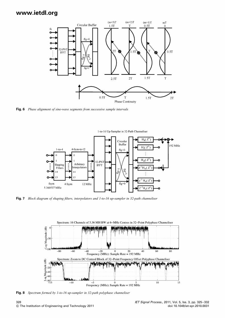
The final modification to the polyphase channeliser is thetime alignment of the phase rotators from the input IFFTand the shifting time origin in the M-path filter. We canunderstand the problem by visualising a single cycle of ascaled sine-wave output from the IFFT that is inserted inthe first column of the path filter memory. From Fig. 5, wenote the locations of the non-zero coefficient in thepolynomials in Z2 and conclude that the input sine-waveonly contributes to the output time samples in the pathfilters located in the upper half of the path set. When thenext scaled sine-wave output from the IFFT is inserted inthe first column of the path filter memory, the previousscaled sine-wave is shifted one column in the memory andit will now contribute to the output time samples from thefilter paths in the lower half of the path filter set. Theproblem is that the sine-wave samples in the lower half ofthe path filter set have the opposite polarity of the sine-wave samples in the upper half of the path filter set. Thesamples from the two half-filter sets are added and to do sothey must have the same phase. The required phase reversalof successive inputs from the IFFT is illustrated in Fig. 6.
We note that this alternating sign effect only occurs for theodd indexed IFFT frequency bins, and those with an oddnumber of cycles per interval. An alternate description ofthe sign reversal is that in the M/2 resampling of themodified M-path filter, the even indexed frequencies alias tomultiples of the input sample rate and the odd indexedfrequencies alias to odd multiples of the half sample rate.
Fig. 5 Comparison of path filter polynomials in Z2 with andwithout additional input delay
327
& The Institution of Engineering and Technology 2011
www.ietdl.org
Fig. 6 Phase alignment of sine-wave segments from successive sample intervals
Fig. 7 Block diagram of shaping filters, interpolators and 1-to-16 up-sampler in 32-path channeliser
Fig. 8 Spectrum formed by 1-to-16 up-sampler in 32-path polyphase channeliser
328 IET Signal Process., 2011, Vol. 5, Iss. 3, pp. 325–332
& The Institution of Engineering and Technology 2011 doi: 10.1049/iet-spr.2010.0031
www.ietdl.org
There are two methods to perform the phase alignment of thesuccessive output vectors from the IFFT. In the first method,we can simply invert the input phase of successive inputsamples to the odd indexed IFFT bins. In the secondmethod, recognising the equivalency of phase shift and timedelay for sinusoids, on alternate outputs from the IFFT wecan apply an M/2 circular shift to its output buffer prior todelivering the phase aligned vector to the path filtermemory. This end around shift of the output buffer occursduring the data transfer in memory and requires noadditional manipulation of the time samples. This form ofthe phase alignment is the mechanism shown in Fig. 6.Fig. 7 shows the block diagram of the signal conditioningand signal processing required to shape, interpolate to12 MHz and up-convert the 16 input channels 1-to-16 inthe 32-path modified polyphase channeliser. Fig. 8 showsthe spectrum output from a single realisation of thisprocessing engine.
Here the output time series of the channeliser has beenheterodyned 23 MHz to centre of the baseband spectrumabout zero frequency. One of the 16 channels hasintentionally been left vacant to illustrate the wide dynamicrange of the processing chain. The lower subplot of Fig. 8is a zoom to the six bands centred about zero frequency.Note the depth of the spectral gap of the vacant channelcentred at 29 MHz is greater than 70 dB below the averagein-band spectral levels. This side-lobe level is due to theselected shaping filter. The out-of-band side-lobe levels dueto the channelisation were designed to be 90 dB below thepeak in-band spectral levels.
3 Total channeliser chain
In the previous section, we developed an alternate channeliserstructure to accommodate input time series which wereshaped and resampled to a sample rate equal to twice the
IET Signal Process., 2011, Vol. 5, Iss. 3, pp. 325–332doi: 10.1049/iet-spr.2010.0031
channeliser channel spacing. Since the input time seriesarrives already up-sampled by 2, we complete the up-sampling by an additional 1-to-M/2 in the M-pathpolyphase channeliser. We accomplished this by up-sampling by M in the M-point IFFT and then down-sampling by 2 in a modified M-path polyphase filter. Aninteresting benefit of this approach is that since the inputtime series is oversampled by 2 and thus has a significantspectral gap between its spectral replicas, the prototypeinterpolation filter designed for the polyphase partition hasa wide transition bandwidth and consequently has a smallnumber of taps. For the 32-path filter demonstrated in theprevious section, each path contained only five coefficientsand achieved 90 dB dynamic range. Remember that thechanneliser is separating the spectral copies of the inputseries with its controlled bandwidth and it is not formingthe channel shapes of the M-channel channeliser.
Once we understand the structure of the M/2 up-sampler,we are free to use it at more than one location in theprocessing chain. Fig. 9 shows the entire processing chainto build the 160-channel channeliser. We see the input tothe chain has grouped the input time series into ten sets of16 input ports. Each of the 16 ports performs the spectralshaping and interpolation to four samples per symbol andthen re-interpolates to the 12 MHz rate for channelisation inthe modified 32-path filter bank. The 16 resampled timeseries in each group forms a super channel that is up-sampled and channelised in the 32-point IFFT with its32-path 2-to-1 down-sampler to obtain a compositebandwidth of 96 MHz at an output sample rate of192 MHz. Ten of these composite signals are presented to a16-point IFFT that up-samples 1-to-16 and then isprocessed by the 16-path polyphase filter that down samples2-to-1 to obtain a single composite bandwidth of 960 MHzat an output sample rate of 1536 MHz. The final post-processing tasks following the 160-channel channeliser is a
Fig. 9 Total processing chain of 160-channel channeliser and post-process to form digital IF
329
& The Institution of Engineering and Technology 2011
www.ietdl.org
Fig. 10 Spectrum at output of 1-to-2 interpolator following the 10-channel combiner in 16-path polyphase filter that performed 1-to-8 up-sample
1-to-2 half-band filter that doubles the sample rate to3072 MHz, a complex to real heterodyne to a digital IFcentred at the quarter sample rate, and a short pre-correctionfilter [8] for the sin(x)/(x) distortion generated by thespectral tilt of the output DAC.
Fig. 10 shows the spectrum formed at the output of the1-to-2 interpolator that processed the time series containingthe 10-blocks of 16 channels, the super-channels, combinedat the output 16-point IFFT and 16-path polyphase filter.Also seen is a zoom to the three spectral blocks centred atDC. To better illustrate the second channelisation process,the 10 sets of input series were each formed with only 15of the 16 input channels occupied. The empty channel waslocated at the channel boundary to more clearly show theseparate spectral boundaries. Fig. 11 shows the spectrumcentred at the quarter sample rate after the heterodyne andconversion to real signal. Also shown is the same spectrumshaped by the sinc response of the output DAC, thefrequency response of the DAC and the frequency responseof the DAC compensating filter. Fig. 12 shows the DACspectral response and distorted spectra of the DAC spectralweighted IF band. Also shown is the spectral zoom to theIF band in the principle Nyquist zone and the spectral
330
& The Institution of Engineering and Technology 2011
response of the compensating filter. Finally, we see thespectrum of the compensated IF band. Here the maximumchange in spectral response level over the 960 MHzbandwidth seems to be less than 0.07 dB.
4 Prior art and other options
A number of other architectural options that could implementthe multichannel channeliser presented in this paper wereconsidered and rejected. It is useful to review these optionsand understand the reasoning that guided us to the selectedsolution. A common building block required of all theoptions is the collection of shape and interpolate filters thatform the multiple input sequences to the channeliser. Thereare 160 of these filters located at the start of the processingblocks shown in Fig. 9. These filters convert the inputsymbol rate to the complex baseband modulators to aconvenient input sample rate required by the multiplechannel channelisers that further up-sample the input streamsand translate their spectra to the selected centre frequencies.
The most direct implementation of the channeliser is thedigital up converter (DUC) formed by a large ratio 1-to-Minterpolator and a complex heterodyne. The interpolator can
Fig. 11 Spectrum at output of heterodyne to quarter sample rate and at output of DAC showing spectral weighting by DAC sinc response, andcompensating filter response
IET Signal Process., 2011, Vol. 5, Iss. 3, pp. 325–332doi: 10.1049/iet-spr.2010.0031
www.ietdl.org
Fig. 12 Spectra: DAC response and weighted signal, zoom to IF centre frequency showing DAC distortion of IF band and compensating filterresponse, and compensated IF band response
be M-path polyphase filters, cascades of half-band filters orK-stage Hogenauer filters with appropriate compensation ofmain-lobe distortion. The Hogenauer filter is a multiple freecascade integrator comb filter with an embedded resampler.It is a popular architecture used in many legacy DUCmodulators often selected for its great flexibility. Theproblem with this architecture is that there is no sharing ofcomputational resources among the multiple channels asthere is an IFFT or polyphase filter and the workload forthe multi-channel channeliser is considerably higher thanthe polyphase option. Chapter 9 in [5] examines the relativeworkload of the dual problem, an M-channel digital downconverter (DDC). In that comparison, the workload for thecollection of individual DDCs is more than 20× theworkload of the typical polyphase channeliser.
We mention here that the overwhelming advantage ofsharing computational resources similarly puts to rest anyinterpolator and translation option that use individualchannel processing. These rejected options include iteratedfilter [5] techniques and spectral masking [5] techniques.
There remain two shared resource options for thechanneliser. The first is the standard coupled M-point IFFTand M-path polyphase partitioned filter. The topic of thispaper is the modified non-maximally decimated version ofthis option. The second option is a version of the tree-basedsynthesis process, which is based on successive half-bandfilters known as the discrete wavelet transform (DWT) [9].The problem with the DWT is the channelisation, and thespectral shaping is performed by the same half-band filtersthat operate in a maximally decimated mode. This causesband edge spectral folding or overlap of adjacent channelswhich is an undesirable attribute when the channels areindividually demodulated as is common in communicationsystems. A variation in the DWT known as interpolated treeorthogonal multiplexing (ITOM) [10] separates the spectralshaping from the channelisation process in the tree structureand thus supports uncoupled multi-channel modulation.
We can bound the workload to form the tree in thefollowing manner. The number of half-band filters at thetop level of the M-branch tree is M/2, each operating at theinput sample rate fS. The number of half-band filters at nextlevel in the tree is M/4, each operating at twice the inputsample rate 2fS. This work load is equivalent to M/2 filtersoperating at fS. We conclude that the workload per level inthe tree is constant, that of the M/2 half-band filters. Sincethe number of filters is halved as we transit between levels,
IET Signal Process., 2011, Vol. 5, Iss. 3, pp. 325–332doi: 10.1049/iet-spr.2010.0031
the number of levels in the tree is log2(M ). Thus, in bothmodes of channelisation, the IFFT with polyphasepartitioned filter and the modified DWT or ITOM havecomputational workloads of (M/2)log2(M ). The workloadper channel is in the order of log2(M )/2 butterflies or half-band filters, respectively. Either option could have beenused for the 160-channel channeliser. Access to standardprogramming cores for the IFFT and the polyphasechanneliser proved to be an important consideration in thefinal choice of the modified polyphase filter bank.
5 Closing comments
We have presented the design and derivation of a modifiedM-path polyphase up-sampling filter bank. This bankaccepts shaped sampled data signals that have beenresampled from two times their individual arbitrary symbolrate to two times the channeliser channel spacing. Themodified M-path polyphase bank up-samples by M in theinput IFFT and then down-samples by 2 in the dual of thenon-maximally decimated filter bank. The unusual benefitof this process is that the filter shaping and resampling isdone prior to the channelisation process. Because of thehigher sample rate of the input sampled data sequences,there is a wide space between its spectral replicas. Thechanneliser suppresses the spectral replicas while up-sampling and channelising and because of the wide spectralgap, the channeliser filters have an unusually small numberof coefficients. In both stages of channelisation described inthis paper, the M-path filters required only five taps per pathto perform the desired channelisation while maintaininggreater than 90 dB adjacent channel isolation.
6 References
1 Harris, F.J., Dick, C., Rice, M.: ‘Digital receivers and transmitters usingpolyphase filter banks for wireless communications’. Special Issue ofMicrowave Theory and Techniques, MTT, Vol. 51, No. 4 April 2003,pp. 1395–1412
2 Harris, F.J., Dick, C.: ‘A modified polyphase transform with embeddedfractional sample rate change’. Int. Signal Processing Conf., Dallas,Texas, 31 March–3 April 2003
3 Harris, F.J., Dick, C.: ‘Performing simultaneous arbitrary spectraltranslation, and sample rate change in polyphase interpolating ordecimating filters in transmitters and receivers’. Software DefinedRadio Conf., San Diego, California, 11–12 November 2002
4 Harris, F.J., Dick, C.: ‘Polyphase channelizer performs sample ratechange required for both matched filtering and channel frequency
331
& The Institution of Engineering and Technology 2011
www.ietdl.org
spacing’. Asilomar Conf. Systems, Signals, and Computers, PacificGrove, CA, 1–3 November 2009
5 Harris, F.J.: ‘Multirate signal processing for communication systems’(Prentice-Hall, 2004), Ch. 7
6 Harris, F.J., Fette, B.: ‘Algorithms for arbitrary resampling filter’.Software Defined Radio Conf., Orlando, Florida, 17–19 November2003
7 Vaidyanathan, P.P.: ‘Multirate systems and filter banks’ (Prentice-Hall,1993)
332
& The Institution of Engineering and Technology 2011
8 Dolecek, G.J., Harris, F.J.: ‘Design of CIC compensator filter in digitalreceiver’, Elsevier DSP J., 2009, 19, (5), pp. 827–837
9 Strang, G., Nguyen, T.: ‘Wavelets and filter banks’ (Wellesley-Cambridge Press, 1997)
10 Harris, F.J., Kjeldsen, E.: ‘A novel interpolated tree orthogonalmultiplexing (ITOM) scheme with compact time-frequencylocalization: an introduction and comparison to wavelet filter banksand polyphase filter banks’. Software Defined Radio Conf., Orlando,Florida, 13–17 November 2006
IET Signal Process., 2011, Vol. 5, Iss. 3, pp. 325–332doi: 10.1049/iet-spr.2010.0031