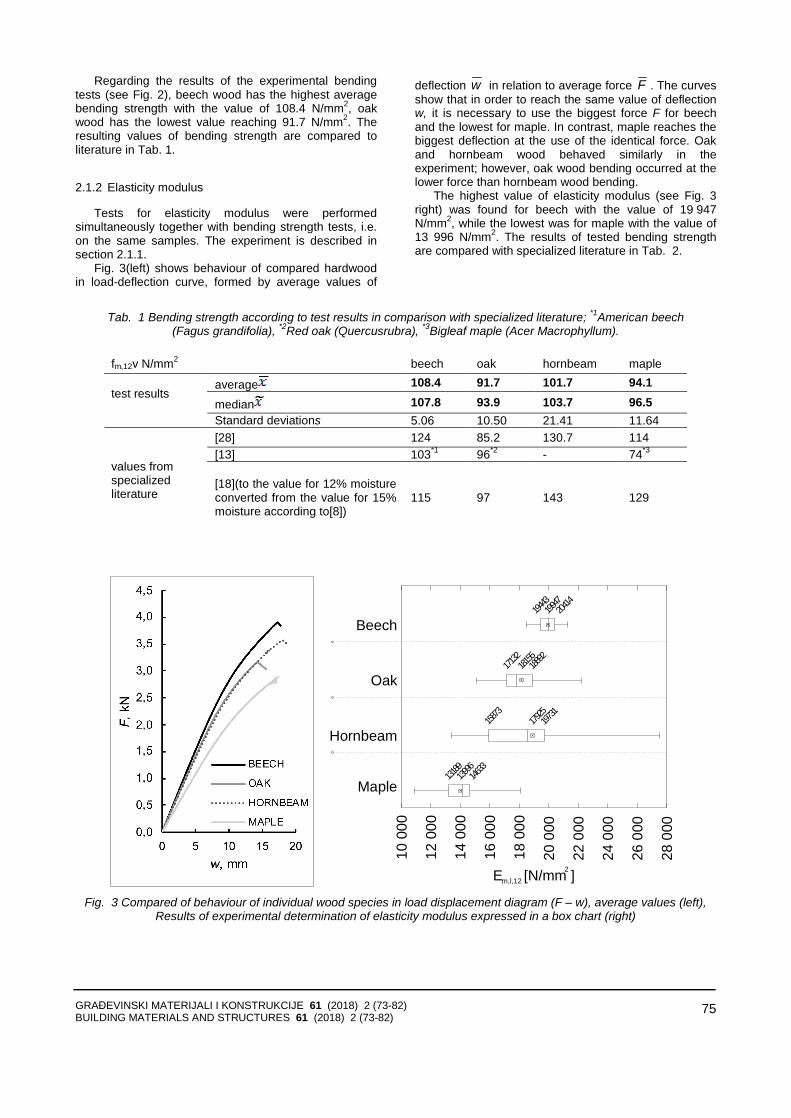
2 ISSN 2217-8139 (Print) UDK: 06.055.2:62-03+620.1+624.001.5(497.1)=861 ISSN 2334-0229 (Online) 2018. GODINA LXI GRAĐEVINSKI MATERIJALI I KONSTRUKCIJE BUILDING MATERIALS AND STRUCTURES Č ASOPIS ZA ISTRA Ž IVANJA U OBLASTI MATERIJALA I KONSTRUKCIJA JOURNAL FOR RESEARCH OF MATERIALS AND STRUCTURES DRUŠTVO ZA ISPITIVANJE I ISTRAŽ IVANJE MATERIJALA I KONSTRUKCIJA SRBIJE SOCIETY FOR MATERIALS AND STRUCTURES TESTING OF SERBIA D DI I M MK K
Č A S O P I S Z A I S T R AŽ I V A N J A U O B L A S T I M A T E R I J A L A I K O N S T R U K C I J AJ O U R N A L F O R R E S E A R C H OF M A T E R I A L S A N D S T R U C T U R E S
DRUŠTVO ZA ISPITIVANJE I ISTRAŽIVANJE MATERIJALA I KONSTRUKCIJA SRBIJESOCIETY FOR MATERIALS AND STRUCTURES TESTING OF SERBIA
DDIIMMKK
DRUŠTVO ZА ISPITIVАNJE I ISTRАŽIVАNJE MАTERIJАLА I KONSTRUKCIJА SRBIJE S O C I E T Y F O R M А T E R I А L S А N D S T R U C T U R E S T E S T I N G O F S E R B I А
GGRRAAĐĐEEVVIINNSSKKII BBUUIILLDDIINNGG MMAATTEERRIIJJAALLII II MMААTTEERRIIААLLSS AANNDD KKOONNSSTTRRUUKKCCIIJJEE SSTTRRUUCCTTUURREESS
ČАS O P I S Z A I S T RАŽ I VАN J A U O B LАS T I MАT E R I JАLА I K O N S T R U K C I JА J O U RNАL F OR R E S EАR C H I N T H E F I E L D O F MАT E RIАL S АN D ST R U CT U R E S
Ш
INTERNATIONAL EDITORIAL BOARD
Professor Radomir Folić, Editor in-Chief Faculty of Technical Sciences, University of Novi Sad, Serbia Fakultet tehničkih nauka, Univerzitet u Novom Sadu, Srbija
Professor Mirjana Malešev, Deputy editor Faculty of Technical Sciences, University of Novi Sad, Serbia - Fakultet tehničkih nauka, Univerzitet u Novom Sadu, Srbija, e-mail: [email protected]
Dr Ksenija Janković Institute for Testing Materials, Belgrade, Serbia Institut za ispitivanje materijala, Beograd, Srbija
Dr Jose Adam, ICITECH Department of Construction Engineering, Valencia, Spain.
Professor Radu Banchila Dep. of Civil Eng. „Politehnica“ University of Temisoara, Romania
Professor Dubravka Bjegović University of Zagreb, Faculty of Civil Engineering, Department of Materials, Zagreb, Croatia
Assoc. professor Meri Cvetkovska Faculty of Civil Eng. University "St Kiril and Metodij“, Skopje, Macedonia
Professor Michael Forde University of Edinburgh, Dep. of Environmental Eng. UK
Dr Vladimir Gocevski Hydro-Quebec, Montreal, Canada
Acad. Professor Yachko Ivanov Bulgarian Academy of Sciences, Sofia, Bulgaria
Dr. Habil. Miklos M. Ivanyi UVATERV, Budapest, Hungary
Professor Asterios Liolios Democritus University of Thrace, Faculty of Civil Eng., Greece
Professor Doncho Partov University of Construction and Architecture - VSU "LJ.Karavelov" Sofia, Bulgaria
Predrag Popović Wiss, Janney, Elstner Associates, Northbrook, Illinois, USA.
Professor Rüdiger Höffery Ruhr University of Bochum, Bochum, Germany
Professor Valeriu Stoin Dep. of Civil Eng. „Poloitehnica“ University of Temisoara, Romania
Acad. Professor Miha Tomažević, SNB and CEI, Slovenian Academy of Sciences and Arts,
Professor Mihailo Trifunac,Civil Eng. Department University of Southern California, Los Angeles, USA
Sekretar redakcije: Slavica Živković, mast.ekon. Lektori za srpski jezik: Dr Miloš Zubac, profesor Aleksandra Borojev, profesor Proofreader: Prof. Jelisaveta Šafranj, Ph D Technicаl editor: Stoja Todorovic, e-mail: [email protected]
PUBLISHER
Society for Materials and Structures Testing of Serbia, 11000 Belgrade, Kneza Milosa 9 Telephone: 381 11/3242-589; e-mail:[email protected], veb sajt: www.dimk.rs
REVIEWERS: All papers were reviewed KORICE: Dijagram dodatnih napona u šini usled termičkih pomeranja konstrukcije gornjeg stroja mosta u
letnjim uslovima za krutost oslonaca K=0 COVER: Diagram of additional stresses in the rail due to temperature change in the bridge deck in summer
conditions for the supports stiffness K=0 Financial supports: Ministry of Scientific and Technological Development of the Republic of Serbia
DRUŠTVO ZА ISPITIVАNJE I ISTRАŽIVАNJE MАTERIJАLА I KONSTRUKCIJА SRBIJE S O C I E T Y F O R M А T E R I А L S А N D S T R U C T U R E S T E S T I N G O F S E R B I А
GGRRAAĐĐEEVVIINNSSKKII BBUUIILLDDIINNGG MMAATTEERRIIJJAALLII II MMААTTEERRIIААLLSS AANNDD KKOONNSSTTRRUUKKCCIIJJEE SSTTRRUUCCTTUURREESS
ČАS O P I S Z A I S T RАŽ I VАN J A U O B LАS T I MАT E R I JАLА I K O N S T R U K C I JА J O U RNАL F OR R E S EАR C H I N T H E F I E L D O F MАT E RIАL S АN D ST R U CT U R E S SАDRŽАJ Dragan D. MILAŠINOVIĆ Smilja ŽIVKOVIĆ GRANIČNA NOSIVOST PRITISNUTE GREDE SA IMPERFEKCIJAMA Originalni naučni rad ................................................. Nikola MIRKOVIĆ Zdenka POPOVIĆ Luka LAZAREVIĆ Milica VILOTIJEVIĆ Aleksandra MILOSAVLJEVIĆ ŽELEZNIČKI MOSTOVI NA INTEROPERABILNIM PRU-GAMA - ASPEKT INTERAKCIJE KOLOSEK/MOST Pregledni rad .............................................................. Dijana MAJSTOROVIĆ Aleksandar BORKOVIĆ Aleksandar PROKIĆ Radovan VUKOMANOVIĆ NEKI ASPEKTI U ANALIZI POPREČNIH SLOBODNIH VIBRACIJA PRIZMATIČNIH GREDA OPTEREĆENIH AKSIJALNOM SILOM Originalni naučni rad ................................................. Marija LAZOVIĆ Biljana DERETIĆ-STOJANOVIĆ Janko RADOVANOVIĆ PRORAČUN NOSIVOSTI I STABILNOSTI UMERENO VITKIH I VITKIH CENTRIČNO PRITISNUTIH KRUŽNIH CFT STUBOVA Originalni naučni rad ................................................. Eva ŠUHAJDOVÁ Miloslav NOVOTNÝ Jan PĚNČÍK Karel ŠUHAJDA Pavel SCHMID Bohumil STRAKA VREDNOVANJE PRIKLADNOSTI IZABRANOG TRVDOG DRVETA U GRAĐEVINARSTVU Originalni naučni rad ................................................. Uputstvo autorima ....................................................
3
19
35
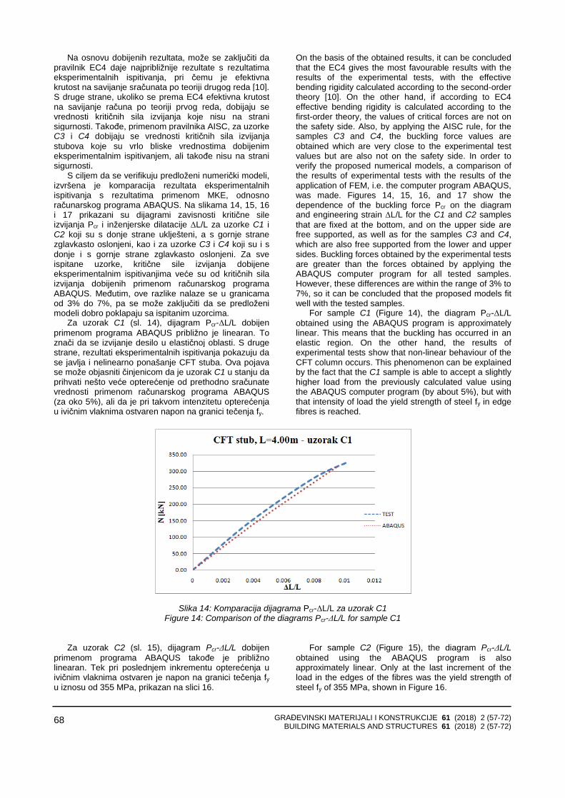
57
73
83
CONTENTS Dragan D. MILASINOVIC Smilja ZIVKOVIC LIMIT LOAD CAPACITY OF COMPRESSED BEAM WITH IMPERFECTIONS Original scientific paper ............................................. Nikola MIRKOVIC Zdenka POPOVIC Luka LAZAREVIC Milica VILOTIJEVIC Aleksandra MILOSAVLJEVIC RAILWAY BRIDGES ON INTEROPERABLE LINES – ASPECT OF TRACK/BRIDGE INTERACTION Review paper............................................................... Dijana MAJSTOROVIC Aleksandar BORKOVIC Aleksandar PROKIC Radovan VUKOMANOVIC SOME ASPECTS OF ANALYSIS OF TRANSVERSE FREE VIBRATIONS OF UNIFORM BEAMS LOADED WITH AXIAL FORCE Original scientific paper .............................................
Marija LAZOVIC Biljana DERETIC-STOJANOVIC Janko RADOVANOVIC STABILITY OF MODERATELY SLENDER AND SLENDER AXIAL LOADED CIRCULAR CFT COLUMNS Original scientific paper .............................................
Eva ŠUHAJDOVÁ Miloslav NOVOTNÝ Jan PĚNČÍK Karel ŠUHAJDA Pavel SCHMID Bohumil STRAKA EVALUATION OF SUITABILITY OF SELECTED HARDWOOD IN CIVIL ENGINEERING Original scientific paper ............................................. Preview report ............................................................
3
19
35
57
73
83
GRAĐEVINSKI MATERIJALI I KONSTRUKCIJE 61 (2018) 2 (3-17) BUILDING MATERIALS AND STRUCTURES 61 (2018) 2 (3-17)
3
GRANIČNA NOSIVOST PRITISNUTE GREDE SA IMPERFEKCIJAMA
LIMIT LOAD CAPACITY OF COMPRESSED BEAM WITH IMPERFECTIONS
Dragan D. MILAŠINOVIĆ Smilja ŽIVKOVIĆ
ORIGINALNI NAUČNI RAD ORIGINAL SCIENTIFIC PAPER
UDK: 624.072.2.046 doi: 10.5937/GRMK1802003M
1 UVOD
Konstrukcije napravljene spajanjem ravnih ploča na njihovim podužnim krajevima veoma su česte. Važan podskup tih konstrukcija koje su glavni predmet ovog rada u suštini jesu prizmatične forme, ali one mogu imati i poprečna ukrućenja koja se koriste u sandučastim nosačima, ukrućenim pločama i pločastim nosačima. Opterećenje je uglavnom takvo da su najveći naponi u pravcu dužine, na primer, aksijalno opterećenje ili uzdužno savijanje.
Analiza ponašanja pločastih konstrukcija odvijala se na nekoliko različitih načina. Jedan od načina bio je sprovođenje sveobuhvatnog istraživanja jednog tipa pločastih konstrukcija, kao što je sandučasti stub, tako da se testira cela familija modela u laboratoriji [1]. Drugi načini bili su numerički, primenom metoda konačnih elemenata (MKE) koji mogu uključiti komplikovane geometrije konstrukcija [2]. Cilj ovog rada jeste da istraži lom grede s početnim imperfekcijama, pojednostavljenim modelima koji se koriste u mehanici, radi poređenja dobijenih rezultata.
Iako je korištenje MKE trenutno dominantno u analizi pločastih konstrukcija, nije tako jednostavno postaviti problem. Za tačnost je poželjno da se koriste manji elementi u zonama gde se čelik izvija lokalno i postaje plastičan, ali nije uvek poznato unapred gde te zone treba de se pojave. Takođe, u analizi ponašanja pločastih konstrukcija može se primeniti i metod konač-nih traka (MKT). MKT se zasniva na svojstvenim funkci-jama koje su izvedene iz rešenja diferencijalne jednačine
Profesor dr Dragan D. Milašinović, dipl. inž. građ., Univerzitet u Novom Sadu, Građevinski fakultet Subotica, Kozaračka 2a, 24000 Subotica, Srbija, imejl: [email protected] Asistent Smilja Živković, dipl. inž. građ., Univerzitet u Novom Sadu, Građevinski fakultet Subotica, Kozaračka 2a, 24000 Subotica, Srbija, imejl: [email protected]
1 INTRODUCTION
The structures, which are made by joining flat plates at their longitudinal edges are very common. An important sub-set of these structures, and which are the main concern of this paper, are those essentially of prismatic form but which can have some transverse stiffening such as is used in box girders, stiffened plates and plate girders. The loading is generally such that the greatest stresses are in the longitudinal direction, e.g. axial loading or longitudinal bending.
Analysis of the behavior of plate structures has been approached in several different ways. One way of carrying out a comprehensive investigation of a single type of plated structures, such as a box-column, would be to test a whole family of models in the laboratory [1]. Other methods were numerically using finite element method (FEM), which may include a complicated geometry of the structures [2]. The aim of this paper is to investigate the fracture of beam with initial imperfections simplified models used in mechanics, in order to compare the results.
Although the use of FEM currently dominant in the analysis of plate structures, the problem set is not so simple. For accuracy it is desirable to use smaller elements in the regions where the steel buckles locally and becomes plastic but it is not always known beforehand where these plastic zones will occurs. Also, the analysis of the behavior of plate structures may be approached using the finite strip method (FSM). The FSM is based on eigen functions, which are derived from
Professor Dragan D. Milašinović, Ph. D., Civ. Eng., University of Novi Sad, Faculty of Civil Engineering Subotica, Kozaračka 2a, 24000 Subotica, Serbia, e-mail: [email protected] Assistant Smilja Živković, M.Sc.Civ. Eng., University of Novi Sad, Faculty of Civil Engineering Subotica, Kozaračka 2a, 24000 Subotica, Serbia, e-mail: [email protected]
GRAĐEVINSKI MATERIJALI I KONSTRUKCIJE 61 (2018) 2 (3-17) BUILDING MATERIALS AND STRUCTURES 61 (2018) 2 (3-17)
4
poprečnih vibracija grede, a pokazao se kao efikasan alat za analiziranje velikog broja konstrukcija kod kojih se i geometrija i svojstva materijala mogu smatrati konstantnim duž podužnog pravca [2]. Ipak, ako se geometrija nosača i opterećenje komplikuju - MKE ima prednost.
Ako se analizira jednostavna konstrukcija – kao što je prosta greda – pojednostavljeni modeli koji se pojavljuju u mehanici korisni su jer mogu dati rešenja kada je problem komplikovan. Takva rešenja mogu dati dovoljno informacija projektantima pri projektovanju konstrukcija. U ovom radu predlaže se jednostavna i vrlo efikasna analiza postavljenog problema granične nosi-vosti pri neelastičnom izvijanju. Polazi se od činjenice da su tankozidne konstrukcije veoma osetljive na početne imperfekcije, pa je njihovo postojanje polazna pretpo-stavka. Elastično rešenje problema dobro je poznato [1]. Međutim, elastično rešenje može se primeniti samo do linije granične nosivosti. Rešenje problema granične nosivosti u području neelastičnosti postignuto je primenom RDA. Primena RDA je jednostavna, jer ona transformiše komplikovan materijalno-nelinearan problem u jednostavan linearno-dinamički problem [3].
2 ODREĐIVANJE LINIJE GRANIČNE NOSIVOSTI PRIMENOM RDA
Faktori koji utiču na graničnu nosivost pri izvijanju mogu biti podeljeni u dve grupe. Prva grupa uključuje geometriju pritisnutog elementa, kao što su poprečni presek i dužina, uslovi oslanjanja, mehanička svojstvamaterijala, uključujući pritom i čvrstoću, kao i uslove okoline, trajanje opterećenja, i tako dalje. Druga grupa faktora koji utiču na graničnu nosivost uključuju geome-trijske i materijalne imperfekcije i njihove varijacije. RDA je viskoelastoplastična teorija, nezavisna od teorije plastičnosti ili nelinearne mehanike loma koja je uspešno primenjena u istraživanju krivih izvijanja stubova [4]. U ovom radu RDA se koristi u istraživanju granične nosivosti tankozidne grede s početnim imperfekcijama.
2.1 RDA – kratak pregled
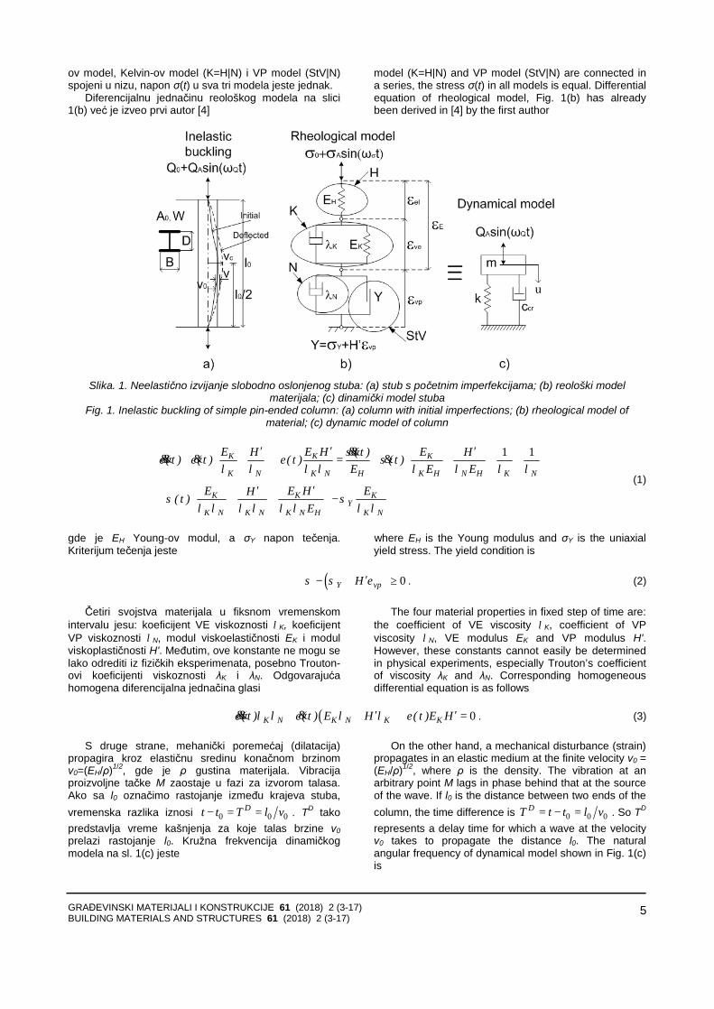
Mikropukotine i deformacije u plastičnom materijalu jesu posledica delovanja spoljašnjih sila na noseći element, što uzrokuje njegovo oštećenje ili lomljenje. Razmotrimo slučaj viskoelastoplastične (VEP) deforma-cije slobodno oslonjenog stuba predstavljenog na slici 1(a). U istraživanju materijala i napon σ(t) i neelastična deformacija ε*(t)=εve(t)+εvp(t) jesu funkcije vremena.
Ako je ukupna VEP deformacija ε (t)=εel+ε*(t) predstavljena kao zbir elastične (trenutne) εel, viskoelastične (VE) εve(t), i viskoplastične (VP) εvp(t), komponente, svaki jednovremeni dijagram napon–deformacija prizmatičnog stuba (npr. s kvadratnim ili kružnim poprečnim presekom A0) može se precizno aproksimirati reološkim modelom materijala H-K-(StV|N), sastavljenim od pet elemenata. Reološki model prikazan je na slici 1(b), koristeći sledeće simbole: N – za Newton-ov model, StV – za Saint-Venant-ov model, H –za Hooke-ov model, "" – za paraleno spajanje modela i "" za spajanje modela u nizu. Zbog toga što su Hooke-
the solution of the beam differential equation of trans-verse vibration, and proved to be an efficient tool for analyzing a great deal of structures for which both geometry and material properties can be considered as constant along a longitudinal direction [2]. However, if the geometry and loading are complicated FEM has the advantage.
If we analyze a simple structure, such as a simple beam, simplified models which are present in mechanics are useful because they can provide solutions when the problem is complicated. Such solutions can provide enough information to designers in the design of structures. In this paper we propose a simple and very efficient analysis of the above problem of the limit load capacity regarding inelastic buckling. The starting point is the fact that the thin-walled structures are very sensitive to initial imperfections, and is the premise of their existence. Elastic solution of the problem is well known [1]. However, the elastic solution can be applied only to the line of limit load capacity. Solving the problem of the limit load capacity in the inelasticity is achieved by using RDA. Application is simple because RDA transforms a complicated material non-linear problem to a simple linear dynamic problem [3].
2 DETERMINATION OF LINE OF LIMIT LOAD CAPACITY USING THE RDA
The factors influencing the limit load capacity may divide into two groups. The first group involves the nominal geometry of the compresses member such as cross-section and length, the support conditions, the material properties including the strength, the sur-rounding climate, the load duration, etc. The second group of factors which influence to the limit load capacity of column involves geometric and material imperfections and their variations. RDA is inelastic theory independent of the theory of plasticity, or non-linear fracture mechanics, which was successfully applied in the study of buckling curves of columns [4]. In this paper, RDA is used in research of the limit load capacity of thin-walled beam with initial imperfections.
2.1 RDA – a short overview
Micro cracks and deformations in the plastic material are consequence of action of external forces to the carrying member, which leads to its damage or breakage. Consider the case of viscoelastoplastic (VEP) strain of a simple pin-ended column presented in Fig. 1(a). In research of the material, both a stress σ(t) and inelastic strain ε*(t) = εve(t)+εvp(t) are functions of time.
If the total VEP strain ε (t) = εel+ε*(t) is presented as a sum of elastic (instantaneous) εel, viscoelastic (VE) εve(t),and viscoplastic (VP) εvp(t), component, each isochronous stress-strain diagram of a prismatic column (e.g., with a square or circular cross section A0) can accurately be approximated by the rheological model of material H-K-(StV|N), consisting of five elements. The rheological model is shown in Fig. 1(b) using the following symbols: N for the Newton’s model, StV for Saint-Venant’s model, H for Hooke’s model, "" for a parallel connection of models and "" for connection of models in a series. Since a Hooke’s model, Kelvin’s
GRAĐEVINSKI MATERIJALI I KONSTRUKCIJE 61 (2018) 2 (3-17) BUILDING MATERIALS AND STRUCTURES 61 (2018) 2 (3-17)
5
ov model, Kelvin-ov model (K=H|N) i VP model (StV|N) spojeni u nizu, napon σ(t) u sva tri modela jeste jednak.
Diferencijalnu jednačinu reološkog modela na slici 1(b) već je izveo prvi autor [4]
model (K=H|N) and VP model (StV|N) are connected in a series, the stress σ(t) in all models is equal. Differential equation of rheological model, Fig. 1(b) has already been derived in [4] by the first author
Slika. 1. Neelastično izvijanje slobodno oslonjenog stuba: (a) stub s početnim imperfekcijama; (b) reološki model
materijala; (c) dinamički model stuba Fig. 1. Inelastic buckling of simple pin-ended column: (a) column with initial imperfections; (b) rheological model of
material; (c) dynamic model of column
1 1K K K
K N K N H K H N H K N
K K KY
K N K N K N H K N
E E H EH ( t ) H( t ) ( t ) ( t ) ( t )E E E
E E H EH( t )E
σε ε ε σ
λ λ λ λ λ λ λ λ
σ σλ λ λ λ λ λ λ λ
′ ′ ′+ + + = + + + + +
′ ′
+ + + −
&&&& & &
(1)
gde je EH Young-ov modul, a σY napon tečenja. Kriterijum tečenja jeste
where EH is the Young modulus and σY is the uniaxial yield stress. The yield condition is
( ) 0Y vpHσ σ ε′− + ≥ . (2)
Četiri svojstva materijala u fiksnom vremenskom
intervalu jesu: koeficijent VE viskoznosti λK, koeficijent VP viskoznosti λN, modul viskoelastičnosti EK i modul viskoplastičnosti H'. Međutim, ove konstante ne mogu se lako odrediti iz fizičkih eksperimenata, posebno Trouton-ovi koeficijenti viskoznosti λK i λN. Odgovarajuća homogena diferencijalna jednačina glasi
The four material properties in fixed step of time are: the coefficient of VE viscosity λK, coefficient of VP viscosity λN, VE modulus EK and VP modulus H'. However, these constants cannot easily be determined in physical experiments, especially Trouton’s coefficient of viscosity λK and λN. Corresponding homogeneous differential equation is as follows
( ) 0K N K N K K( t ) ( t ) E H ( t )E Hε λ λ ε λ λ ε′ ′+ + + =&& & . (3)
S druge strane, mehanički poremećaj (dilatacija) propagira kroz elastičnu sredinu konačnom brzinom v0=(EH/ρ)1/2, gde je ρ gustina materijala. Vibracija proizvoljne tačke M zaostaje u fazi za izvorom talasa. Ako sa l0 označimo rastojanje između krajeva stuba, vremenska razlika iznosi 0 0 0
Dt t T l v− = = . TD tako predstavlja vreme kašnjenja za koje talas brzine v0prelazi rastojanje l0. Kružna frekvencija dinamičkog modela na sl. 1(c) jeste
On the other hand, a mechanical disturbance (strain) propagates in an elastic medium at the finite velocity v0 = (EH/ρ)1/2, where ρ is the density. The vibration at an arbitrary point M lags in phase behind that at the source of the wave. If l0 is the distance between two ends of the column, the time difference is 0 0 0
DT t t l v= − = . So TD
represents a delay time for which a wave at the velocity v0 takes to propagate the distance l0. The natural angular frequency of dynamical model shown in Fig. 1(c) is
GRAĐEVINSKI MATERIJALI I KONSTRUKCIJE 61 (2018) 2 (3-17) BUILDING MATERIALS AND STRUCTURES 61 (2018) 2 (3-17)
6
0 0
0 0 0 0
1 1HD
E A vkm l A l l T
ωρ
= = = = (4)
gde je m masa stuba, a k njegova aksijalna krutost.
Imajući u vidu jednačinu (3), izraz sličan (4) može se formulisati postavljanjem reološkog modela stuba u stanje kritičnog viskoznog prigušenja (c=ccr)
where m is the mass of the column and k its axial stiffness.
Heaving in mind Eq. (3), we can formulate expression similar to Eq. (4), turning the rheological model into the state of critical viscous damping (c = ccr )
1 1KD
K N K
E HT T T
ωλ λ ∗
′= = =
(5)
gde su: where:
* * D
K K N K K K N KE H , E T , H T ,T T Tλ λ λ λ′ ′= = = = = .
Ako zamenimo K Nλ λ⋅ sa m γ⋅ ,
K N KE Hλ λ′⋅ + ⋅ sa crc γ⋅ i KE H ′⋅ sa k γ⋅ , jednačina (3) postaje
Replacing K Nλ λ⋅ by m γ⋅ , K N KE Hλ λ′⋅ + ⋅ by
crc γ⋅ and KE H ′⋅ by k γ⋅ , Eq. (3) becomes.
0cr( t )m ( t )c ( t )kε ε ε+ + =&& & (6)
gde su where:
2DK Nm k Tλ λ
γ= = ⋅ , 2 DK N K
crE H
c k Tλ λ
γ′+
= = ⋅ ⋅ , KE Hkγ
′= . (7)
γ je zapreminska težina materijala. Prema navedenom, propagacija talasa kroz elastičnu
sredinu predstavlja fizičku osnovu za postavljanje analogije između dva različita fizička fenomena –reološkog i dinamičkog, nazvana RDA. Na osnovu RDA, vrlo komplikovan materijalno nelinearan problem u području VEP deformacija može se rešiti kao jednostavan linearno-dinamički problem. RDA je izvedena da reši dinamičke probleme [4], ali može se koristiti i u analizi kvazistatičkih problema, imajući u vidu odgovarajuće granične vrednosti izvedenih analitičkih izraza. Na primer, svaki kvazistatički dijagram napon–deformacija može se dobiti korišćenjem RDA modul funkcije [3], uključujući čvrstoću na pritisak, što je ključni parametar za analizu energije loma.
2.2 Strukturalno-materijalna konstanta
Korišćenje tangentnog modula umesto Young-ovog modula (na osnovu Engesser-ove pretpostavke
2 2En TEσ π λ= ) pokazalo se realnim u slučaju
neelastičnog izvijanja, a to su potvrdila i eksperimentalna istraživanja. U radu [4] prvi autor pokazao je da je RDA modul jednak tangentnom modulu ( ( )0R TE t,t E= ) u
fiksnom vremenskom intervalu ( )0t ,t . Zbog ovoga se u razmatranje postavljenog problema uvodi RDA modul funkcija ER. Ona je već korištena za formulaciju kvazistatičkog napon–deformacija dijagrama standard-nog betonskog cilindra [3], kako sledi
γ is the specific gravity. Accordingly, the elastic wave propagation
constitutes the physical basis for setting up an analogy between two different physical phenomena, rheological and dynamical, called RDA. Based on RDA, a very complicated non-linear problem in the range of VEP strains can be solved as a simple linear dynamic problem. RDA is derived to solve the dynamic problems [4], but can be used also in the analysis of the quasi static problems taking into account the corresponding limit values of derived analytical expressions. For example, each quasi static stress-strain diagram can be obtained by using the RDA modulus function [3], including the compression strength, which is a key parameter for the analysis of fracture energy.
2.2 Structural-material constant
The utilisation of the tangent modulus instead of Young modulus (according to the Engesser assumption
2 2En TEσ π λ= ) proved to be realistic in the case of
inelastic buckling, based on the and experimental researches. In [4], the first author has shown that RDA modulus is equal to the tangent modulus ( ( )0R TE t,t E= ) within a fixed time interval ( )0t ,t . Because of this, in consideration of the above problem is introduced RDA modulus function ER. It has already been used for the formulation of the quasi-static stress-strain diagram of the standard concrete cylinder [3], as
( ) ( ) ( ) ( ) ( )1 10 0 0
cr cr crcr cr E
RK
E E Eσ σ σ
ε ϕ σ= = + = + . (8)
GRAĐEVINSKI MATERIJALI I KONSTRUKCIJE 61 (2018) 2 (3-17) BUILDING MATERIALS AND STRUCTURES 61 (2018) 2 (3-17)
7
gde je E(0) modul elastičnosti materijala u inicijalnom, neoštećenom stanju, a KE je strukturalno-materijalna konstanta. Na osnovu (8), sledi kvadratna jednačina
where E(0) is the initial elastic modulus in undamaged state, and KE is the structural-material constant. According to Eq. (8) the quadratic equation follows
( )2 0 0cr E crK Eσ σ ε+ − = . (9)
Koren jednačine (9), koristeći početne uslove ( )0 0ε = i ( )0 0crσ = , kritična je vrednost napona za
odabranu deformaciju ε krive linije napon–deformacija. Tako je
The root of Eq. (9), using the initial conditions ( )0 0ε = and ( )0 0crσ = , is the critical value of stress
for the selected deformation ε of stress-strain curve. Thus
( )( )1 1 4 0 1
2cr EE
K EK
σ ε= + − . (10)
Na granici elastičnosti nagib je jednak Young-ovom modulu EH (poznata vrednost). Zbog toga, jeste
( )0R HE E= , tako da sledi
At the limit of elasticity the slope is equal to the Young modulus EH (a known value). Because of that
( )0R HE E= , so we get
( ) ( )0 1HE E ϕ∗= + . (11)
gdje je ϕ∗ strukturalno-materijalni koeficijent tečenja na granici elastičnosti. U radu [4] prvi autor na granici elastičnosti odredio je presek Euler-ove i RDA krive izvijanja, iz koga sledi vitkost na granici elastičnosti
where ϕ∗ is the structural-material creep coefficient at the limit of elasticity. In [4], the first author has defined the intersection of the Euler and RDA buckling curves at the limit of elasticity, from which follows the slenderness at the limit of elasticity
32 1
E *iI
λ πγϕ
= . (12)
gde je 0i I / A= minimalni radijus inercije. Nadalje, Euler-ov kritični napon slobodno oslonjenog stuba
2 2E H EEσ π λ= koristi se za izračunavanje
strukturalno-materijalne konstante na granici elastičnosti, kako je pokazano u [3]
where 0i I / A= is the minimum radius of gyration. Further, Euler’s critical stress of a simple pin-ended column 2 2
E H EEσ π λ= is used to calculate the structural-material constant at the limit of elasticity, as explained in [3]
*
EE
K ϕσ
= . (13)
Iza granice elastičnosti, koristi se zakon linearne promene kritičnog napona u odnosu na kritični koeficijent tečenja (zakon toka), kako je definisao Milašinović [3]
Beyond the limit of elasticity the law of linear changes of the critical stress level in relation to the critical creep coefficient (flow law) is used, as defined in Milašinović [3]
1cr cr
EKσ ϕ= . (14)
Na osnovu svega, funkcija RDA modula glasi Accordingly, the RDA modulus function is as follows
11 11 1
H HR *
cr cr E
H H
E EEK
E E Hϕ σϕ
= = =+ +
+ +′
. (15)
gde je kritični koeficijent tečenja where the critical creep coefficient is
* Hcr cr E
E KH
ϕ ϕ σ= + =′
. (16)
i koji uključuje neelastični deo koeficijenta tečenja ine HE Hϕ ′= .
and which includes the inelastic part of creep coefficient ine HE Hϕ ′= .
GRAĐEVINSKI MATERIJALI I KONSTRUKCIJE 61 (2018) 2 (3-17) BUILDING MATERIALS AND STRUCTURES 61 (2018) 2 (3-17)
8
2.3 Kritična varijabla oštećenja
Budući da rast mikropukotina smanjuje krutost materijala, oštećeno stanje materijala opisano je varijacijom modula elastičnosti EH, Lemaitre [5]. Shodno tome, varijabla oštećenja D uvedena je na osnovu hipoteze o ekvivalenciji deformacije između oštećenog i neoštećenog materijala, kako sledi
2.3 Critical damage variable
Since that growth of micro cracks reduces the stiffness of the material, the damaged state of material is described by the variation of Young modulus EH, Lemaitre [5]. Hence, the damage variable D is introduced based to the hypotheses of strain equivalence between the damaged and undamaged material, as follows
( ) ( )1 HE D D E= − . (17)
U radu [3] prvi autor ovog rada uveo je pretpostavku da je E(D) jednak RDA modulu, na osnovu čega je definisana varijabla oštećenja D. Ova pretpostavka koristi se i u ovom radu. Kako je tačka C1 na liniji granične nosivosti, koja je ujedno i linija kritičnih napona u neelastičnoj oblasti, varijabla oštećenja koja sledi jeste kritična
In [3], the first author of this paper has introduced the assumption that the E(D) is equal to the RDA modulus on the basis of which the damage variable D is defined. This assumption is also used in this paper. As the point C1 is on the line of limit load capacity, which is the line of critical stresses in the inelastic range of strain, damage variable below is the critical
( )
( )( )
( )
21 11
1 12 22 21 1
111
1 1C CC
C H R H CC C
D E E E Dϕ ϕϕ δ
ϕ δ ϕ δ
++ +− = = ⇒ =
+ + + +. (18)
gde je 1Cϕ koeficijent tečenja u tački C1 na osnovu zakona toka (14)
where 1Cϕ is the creep coefficient at the point C1, according to the flow law (14)
1 1C C EKϕ σ= . (19)
DTσ σδ ω ω ω= = jeste relativna frekvencija u kojoj je
σω kružna frekvencija pobude. U slučaju kvazistatičkog opterećenja sledi δ → 0, pa je kritična varijabla oštećenja
DTσ σδ ω ω ω= = is the relative frequency where σωis the angular frequency of excitation. In the case of quasi-static loading follows δ → 0, and critical damage variable is
11
11C
CC
Dϕ
ϕ=
+. (20)
Na ovaj način, oštećenje na liniji granične nosivosti u slučaju kvazistatičkog opterećenja opisano je skalarnom veličinom DC1 koja uzima vrednosti između 0 i 1.
2.4 Linija granične nosivosti dobijena primenom RDA
Na graničnu nosivost značajno utiču geometrijske i materijalne imperfekcije greda, kao i njihove varijacije. Zbog toga je ovaj problem veoma komplikovan. U ovom radu razmatraju se čistogeometrijske imperfekcije. To podrazumeva da samo referentna geometrija zavisi od imperfekcija, a da naponsko stanje ne zavisi.
Prema RDA, neelastičan ugib grede u slučaju kvazistatičkog opterećenja jeste [3]
In this way, the damage at the line of limit load capacity is described by a scalar value DC1, which takes a value between 0 and 1.
2.4 Line of limit load capacity obtained using the RDA
Geometric and material imperfections, as well as their variations can significantly affect to the limit load capacity of beams. This is why this problem is very com-plicated. Purely initial geometric imperfections are consi-dered here. It implies that only the reference geometry is influenced by imperfection, not the stress state.
According to RDA, inelastic deflection o the beam in the case of quasi-static load is [3]
( )1 1 1 *
cv a ϕ= + . (21)
gde a1 je početna imperfekcija u sredini dužine grede. Opterećenje u tački C1 odgovara graničnoj nosivosti
za datu početnu imperfekciju a1. U tankozidnim konstrukcijama, granična nosivost skoro je jednaka naponu tečenja materijala σY. Stoga, opravdano je koristiti napon tečenja kao kriterijum loma. Zbog toga, za gredu izloženu aksijalnoj sili QC1 i odgovarajućem momentu savijanja 1 1C cQ v⋅ dobijamo
where a1 is the initial imperfection at mid-length. The load at point C1 corresponds to the limit load
capacity for the given initial imperfection a1. In thin-walled structures, the limit stress is almost equal to the yield stress of the material σY. Hence, it is justified to use of the yield stress as the criterion of failure. Therefore, for the beam subjected to an axial force QC1 and an appropriate bending moment, 1 1C cQ v⋅ we obtain as follows
GRAĐEVINSKI MATERIJALI I KONSTRUKCIJE 61 (2018) 2 (3-17) BUILDING MATERIALS AND STRUCTURES 61 (2018) 2 (3-17)
9
( )1 1 1 0
1 10 0 1 1
C C c YC Y C *
Q Q v A WQ
A W W A aσ
σ σϕ
⋅= + = ⇒ =
+ +. (22)
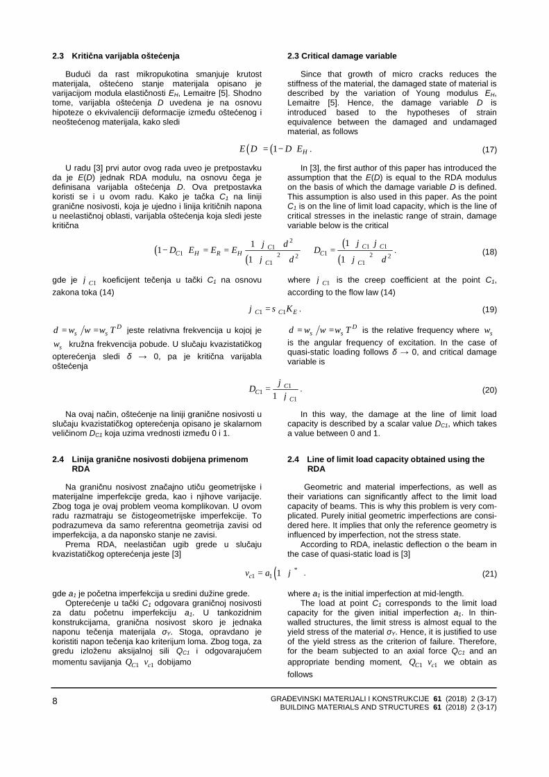
gde je W elastični otporni moment. Kriva linija QC-vc dobija se pretpostavljanjem niza
početnih imperfekcija a1. Ovo je linija granične nosivosti dobijena primenom RDA. Ova linija pokazuje normalno omekšavajuće ponašanje grede, slika 2(a).
where W is the elastic section modulus. The curve line QC-vc is obtained by assuming a
series of the initial imperfections a1. This is the line of limit load capacity obtained using the RDA. This line shows normal softening behavior of beam, Fig. 2 (a).
Slika 2. (a) Linija granične nosivosti i linije loma, dobijene primenom RDA; (b) dijagram napon-deformacija normalnog
omekšavajućeg ponašanja materijala Fig. 2. (a) Line of limit load capacity and failure lines obtained using the RDA; (b) stress-strain diagram of normal
softening behavior of material 3 ODREĐIVANJE LINIJA LOMA
Na početku poglavlja 2 opisani su faktori koji utiču na graničnu nosivost konstrukcija. Međutim, kombinacija ovih faktora može dovesti do veoma različitih oblika lomova grede, koji se kreću od krtog do izrazitoduktilnog. Oblik loma usko je povezan s linijama loma koje se pojavljuju u postkritičnom stanju, nakon što je granična nosivost dostignuta. U ovom poglavlju, daju se rešenja linija loma prema teoriji elastičnosti i teoriji plastičnosti, s ciljem pojašnjenja linija granične nosivosti, dobijenih primenom RDA.
3.1 Elastične linije loma
Ako analiziramo gredu poprečnog preseka A0 i s početnom imperfekcijom a1, elastična linija loma (hiperbola) dobro je poznato rešenje problema granične nosivosti – slika 2(a). Asimptota rešenja jeste Euler-ovo kritično opterećenje QE, [1]
3 DETERMINATION OF FAILURE LINES
At the beginning of Section 2 are described factors which affect the limit load capacity. However a combination of these factors can lead to a substantially different shape of fracture of the beam, which range from brittle to extremely ductile. The shape of the fracture is closely associated with failure lines that appear in post-critical state, after the limit load capacity is reached. In this section, solutions are given for the failure lines according to the theory of elasticity and plasticity theory in order to compare with solutions obtained by the RDA.
3.1 Elastic failure lines
If we analyze the beam with a constant cross-section A0 and initial imperfection a1, elastic failure line (hyperbola) is well known solution for elastic problem of the limit load capacity, Fig. 2(a). The asymptote of solution is Euler’s critical load QE, [1]
11
11c
C
E
avQQ
=−
. (23)
Napon u tački C1 jeste suma od aksijalnog napona i napona savijanja. Mi izjednačavamo ovaj napon s
The stress at point C1 is the summation of the axial stress and bending stress. We equates this stress with
GRAĐEVINSKI MATERIJALI I KONSTRUKCIJE 61 (2018) 2 (3-17) BUILDING MATERIALS AND STRUCTURES 61 (2018) 2 (3-17)
10
naponom tečenja σY, pod pretpostavkom plastičnog loma grede
yield stress σY, assuming plastic failure of the beam
1 1 1 1 1 11
10 0 1
C C c C CC Y
C
E
Q Q v Q Q aQA W A WQ
σ σ= + = + =−
. (24)
Tako, elastična granična nosivost glasi Thus, the elastic carrying capacity is as follows
( ) ( )2 21 0 0 1 0 0 0
14
2E E Y E E Y Y E
CQ W a Q A A W Q W a Q A A W W Q A
QW
σ σ σ+ + − + + −= . (25)
Hiperbola Q-vc može biti konstruisana izborom niza sila Q. Međutim, treba imati u vidu i to da se kada je reč o realnom materijalu hiperbola može primeniti samo do linije granične nosivosti, dobijene primenom RDA u poglavlju 2.4, odnosno do granične nosivosti QC1.
Ako je opterećenje veće od opterećenja QC1, onda je moguće da se pojave linije loma na osnovu novih ravnotežnih stanja. Kao što je pomenuto u [1], u tankozidnim konstrukcijama postoje dva važna razloga za formiranje linija loma, slika 2(a). Prvi razlog odnosi se na nagib linije granične nosivosti, a drugi razlog jeste to što se u tankozidnim konstrukcijama ne razvijaju jednostavni plastični zglobovi. Jednostavan plastični zglob javlja se samo pod pravim uglom u odnosu na neutralnu osu grede izložene čistom savijanju.
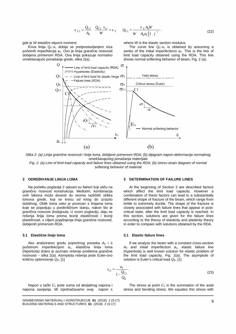
3.2 Plastična linija loma za jednostavan plastični zglob
Linija loma za jednostavan plastični zglob može se aproksimirati metodom objašnjenom u [6], slika 3(a).
Hyperbola Q-vc can be constructed by selecting a series of force Q. However, it should be noted that in a real material a hyperbola can be applied only to the line of limit load capacity, which is obtained by the application of RDA in Section 2.4, that is, up to the critical load QC1.
If load is greater than load QC1 then it is possible to appear failure lines based on the new equilibrium states. As mentioned in [1], in the thin-walled structures there are two important reasons for the formation of the failure lines, Fig. 2(a). The first reason is related to the slope of the line of limit load capacity, while the second reason is that in thin-walled structures can not be developed a simple plastic hinges. Simple plastic hinge occurs only at a right angle to the neutral axis of a beam subjected to pure bending.
3.2 Plastic failure line for simple plastic hinge
Failure line for simple plastic hinge can be approximated by the method explained in [6], Fig. 3(a).
Slika 3. (a) metod objašnjen u [6]; (b) jednostavan plastični zglob
Fig. 3. (a) method explained in [6]; (b) A simple plastic hinge
Prema radu [6], pretpostavlja se da rebro prihvata aksijalnu silu Q, dok preostali deo poprečnog preseka prihvata moment savijanja M. Kada se neutralna osa nalazi u rebru ( 0 2z d≤ ), polovina dubine plastične zone i moment savijanja računaju se prema izrazima
According to [6] it is assumed that the web accepts axial force Q, while the remainder part of cross-section accepts bending moment M. When the neutral axis is in the web ( 0 2z d≤ ), half the depth of plastic zone of and bending moment are calculated according to equations
GRAĐEVINSKI MATERIJALI I KONSTRUKCIJE 61 (2018) 2 (3-17) BUILDING MATERIALS AND STRUCTURES 61 (2018) 2 (3-17)
11
0 2 Y
Qztσ
= , ( )2
202 Y
dM BT D T z t σ = − + +
. (26)
Kada je neutralna osa u flanšama ( 02 2d z d T≤ ≤ + ), dubina plastične zone i moment savijanja računaju se prema izrazima
When the neutral axis is in the flanges ( 02 2d z d T≤ ≤ + ), the depth of plastic zone and bending moment are calculated according to equations
0 2 2Y
Y
Q td dzBσσ
−= + ,
2202 Y
DM z Bσ = −
.. (27)
Tako, imajući u vidu vrednosti Q i M, ugib u sredini dužine glasi
Thus, taking into account the values of Q and M, the deflection at mid-length is as follows
c
MvQ
= . (28)
Linija loma Q-vc za jednostavan plastični zglob može biti konstruisana izborom niza sila Q.
3.3 Linije loma – dobijene primenom RDA
Ako je opterećenje veće od opterećenja QC1 greda je u novom, izvijenom ravnotežnom stanju. U slučaju normalnog omekšavanja, samo granična nosivost QC1mora opadati, dok se ugib grede povećava. Primena RDA polazi od granice elastičnosti. Zbog toga, za odabranu početnu imperfekciju a1 konstruiše se hiperbo-la, te se sračunava elastična granična nosivost QC1. Za odgovarajući napon σC1 = QC1/A0 vitkost grede jeste
Failure line Q-vc for simple plastic hinge may be constructed by selecting a series force Q.
3.3 Failure lines obtained using the RDA
If the load is greater than load QC1, a beam is in the new buckling equilibrium. In the case of normal softening the ultimate carrying capacity QC1 must decreases only, while the deflection increases. Application of RDA starts from the limit of elasticity. Therefore, for the selected initial imperfection a1 a hyperbole may be constructed and the limit load capacity QC1 calculated. For the corresponding stress σC1 = QC1/A0, the slenderness of a beam is
1
1
HC
C
Eλ π
σ= . (29)
Prema radu [4], koeficijent tečenja 1Cϕ jeste According to [4], the creep coefficient 1Cϕ is
32
11
1C
C
iI
ϕ πγλ
= . (30)
1Cϕ jeste ključni parametar za testiranje omekša-vajućeg ponašanja, slika 2(b). Na osnovu zakona toka (14), strukturalno-materijalna konstanta jeste
1Cϕ is a key parameter for the testing of the softening
behavior of the material, Fig. 2(b). Based on the flow law (14) the structural-material constant is as follows
11
1
CC
CK
ϕσ
= . (31)
RDA modul u prvoj iteraciji (1) jeste RDA modulus in the first iteration (1) is
( )11
11H
RCC
EEϕ
=+
. (32)
Zatim, napon u prvoj iteraciji jeste Then the stress in the first iteration (1) is
( )( )12
1 11 2
1
RCC
C
Eπσ
λ= . (33)
RDA modul u drugoj iteraciji (2) jeste RDA modulus in the second iteration (2) is
GRAĐEVINSKI MATERIJALI I KONSTRUKCIJE 61 (2018) 2 (3-17) BUILDING MATERIALS AND STRUCTURES 61 (2018) 2 (3-17)
12
( )( )
21 1
11H
RCC
EEϕ
=+
. (34)
gde je
where
( ) ( )1 11 1 EC C Kϕ σ= . (35)
Iterativni postupak objašnjen u [4] nastavlja se sve do konvergencije u rešavanju problema, to jest kada novi RDA modul više ne menja napon. Ugibi u sredini grede moraju se računati putem iteracija – kako sledi
Iterative method, which is explained in [4] continues until convergence in solving the problem, i.e. when the new RDA modulus does not change the stress. Deflection in the mid-length of beam must be calculated through iterations as follows
( ) ( )( )111 1i i
ccv v ϕ −= + . (36)
4 NUMERIČKA ANALIZA
Numerička analiza sprovodi se na prostoj gredi s tankozidnim poprečnim presekom. Početne imperfekcije a1 = 0.1, 1.5 i 5 mm izmerene su na sredini visine grede [1]; greda se savija oko jače ose. Detalji poprečnog preseka uzeti su iz [1] i prikazani su na slici 4. Greda je napravljena od čelika sledećih mehaničkih karakteristika EH = 206 GPa, µ = 0.3 i σY = 250 MPa. Pretpostavljeno je da savijena greda formira jednostavan plastični zglob u sredini dužine.
4 NUMERICAL ANALYSIS
Numerical analysis is carried out in a simple beam with the thin-walled cross-section. The initial imperfec-tions of a1 = 0.1, 1.5 and 5 mm are measured at mid-height of beam [1] and beam bending takes place about the stronger axis. Details the cross-section was taken from [1] and is shown in Fig. 4. The beam is made of steel of the following mechanical characteristics of EH = 206 GPa, µ = 0.3 i σY = 250 MPa. It is assumed that bending beam forms a simple plastic hinge in the mid-length.
Slika 4. Greda s jednostavnim plastičnim zglobom u sredini dužine Fig. 4. Beam with a simple plastic hinge in the mid-length
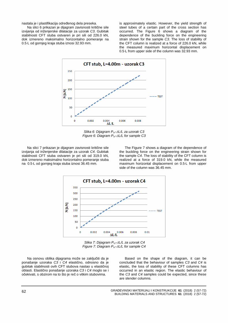
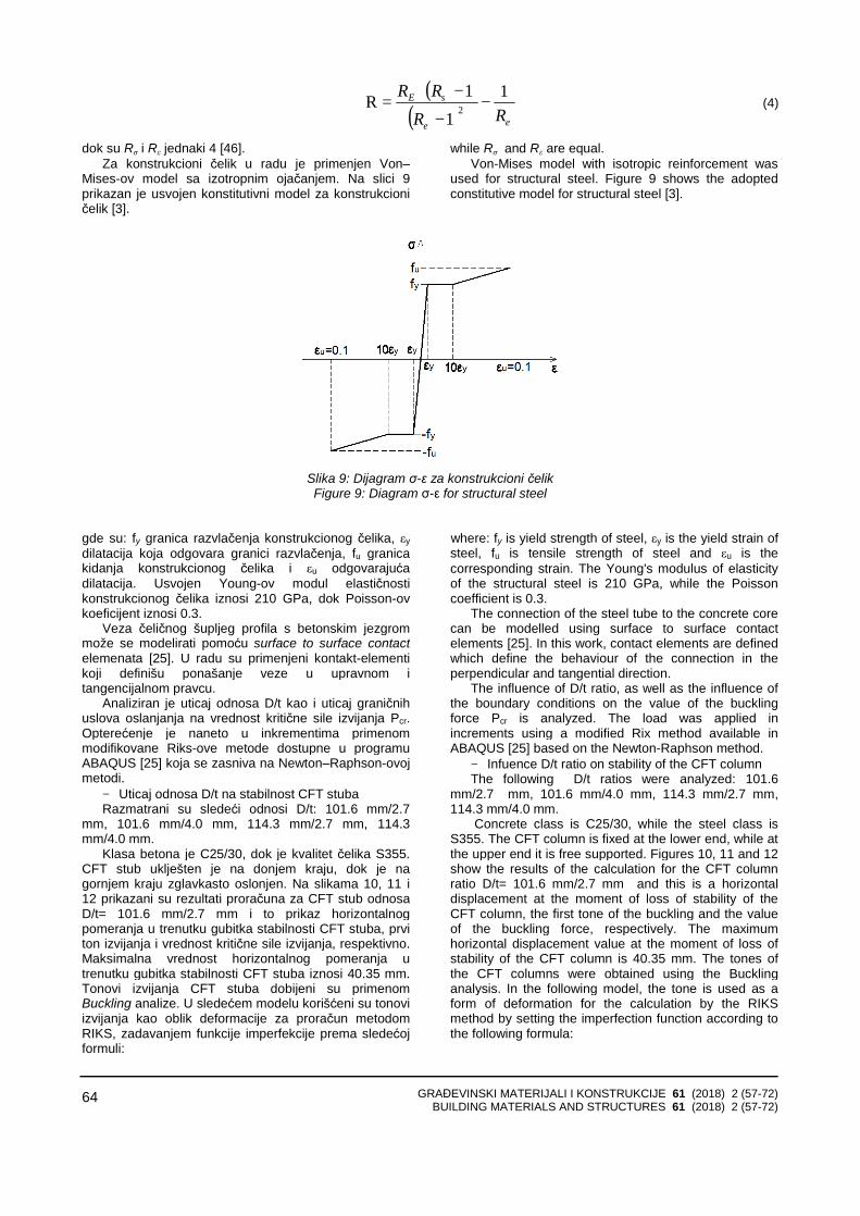
Slika 5 prikazuje Q-vc linije granične nosivosti za tri izmerene imperfekcije prema [1]. Linija granične nosivosti, dobijena primenom RDA, nalazi se u elasto-plastičnoj oblasti, ispod plastične linije loma za jednostavan plastični zglob.
Tečenje počinje kada napon u spoljnim vlaknima poprečnog preseka grede dostigne napon tečenja σY. Linija početka tečenja (slika 6) izračunava se prema Bernoulli–Euler-ovoj teoriji savijanja.
Slika 6 prikazuje linije loma dobijene primenom RDA, koje se pojavljuju u postkritičnom stanju grede, nakon što je granična nosivost dostignuta. U slučaju početne imperfekcije a1 = 0.1 mm, lom se dešava u elastičnoj oblasti, jer linija loma leži ispod linije početka tečenja. Zbog toga, greda se ponaša krto iako je čelik duktilan materijal. Ovakvo krto ponašanje grede nije poželjno. U druga dva slučaja (a1 = 1.5 i 5 mm), lom grede je
Fig. 5 presents Q-vc lines of limit load capacity for the three measured imperfections [1]. Line of load capacity that obtained by RDA is located in the elastic-plastic failure zone under the plastic failure line for simple plastic hinge.
Yield of cross-section starts when stress in the outermost fiber reaches the yield stress σY. Initial yield line, Fig. 6 is calculated according to the Bernoulli-Euler’s bending theory.
Fig. 6 shows the failure lines obtained using the RDA, such as occur in a post-critical state of beam, after the limit load capacity is reached. In the case of initial imperfection of a1 = 0.1 mm failure occurs in the elastic zone, because the failure line lies below the initial yield line. Because of this beam behaves brittle although the steel is ductile material. This brittle behavior of the beam is not desirable. In other two cases (a1 = 1.5 and 5 mm)
GRAĐEVINSKI MATERIJALI I KONSTRUKCIJE 61 (2018) 2 (3-17) BUILDING MATERIALS AND STRUCTURES 61 (2018) 2 (3-17)
13
duktilan u elasto-plastičnoj oblasti. Duktilnost je veća kod većih početnih imperfekcija. Linije loma opisuju normalno omekšavajuće ponašanje. To je slučaj negativnih ugiba (dQC/dvc<0), slika 2(a). To znači da se granična nosivost smanjuje, a raste ugib grede. Isti omekšavajući efekat već se dobio putem napon–deformacija relacije u radu [7].
the failure of the beam is ductile in the elastic-plastic zone. Ductility is greater at higher initial imperfections. Failure lines describe the normal softening behavior. This is the case of negative slope (dQC/dvc<0), Fig. 2(a).This means that the limit load capacity decreases, while the deflection increases. The same softening effect has already been obtained through the stress-strain relation in the paper [7].
0
20
40
60
80
100
120
140
160
180
0 10 20 30 40 50
Mid-length deflection vc (mm)
Load
Q (k
N)
Load capacity (RDA) Load capacity (Plastic hinge)Critical load (Euler) Hyperbola: a1=0.1 mmHyperbola: a1=1.5 mm Hyperbola: a1=5.0 mm
Slika 5. Uticaj početnih imperfekcija na linije granične nosivosti
Fig. 5. Influence of initial imperfections on the lines of limit load capacity
0
20
40
60
80
100
120
140
160
180
0 10 20 30 40 50
Mid-length deflection vc (mm)
Load
Q (k
N)
Load capacity (RDA) Critical load (Euler)Failure curve a1=1.5 mm Failure curve a1=0.1 mmFailure curve a1=5.0 mm Initial yield line
Slika 6. Uticaj početnih imperfekcija na linije početka tečenja i linije loma
Fig. 6. Influence of initial imperfections on the initial yield line and failure lines
GRAĐEVINSKI MATERIJALI I KONSTRUKCIJE 61 (2018) 2 (3-17) BUILDING MATERIALS AND STRUCTURES 61 (2018) 2 (3-17)
14
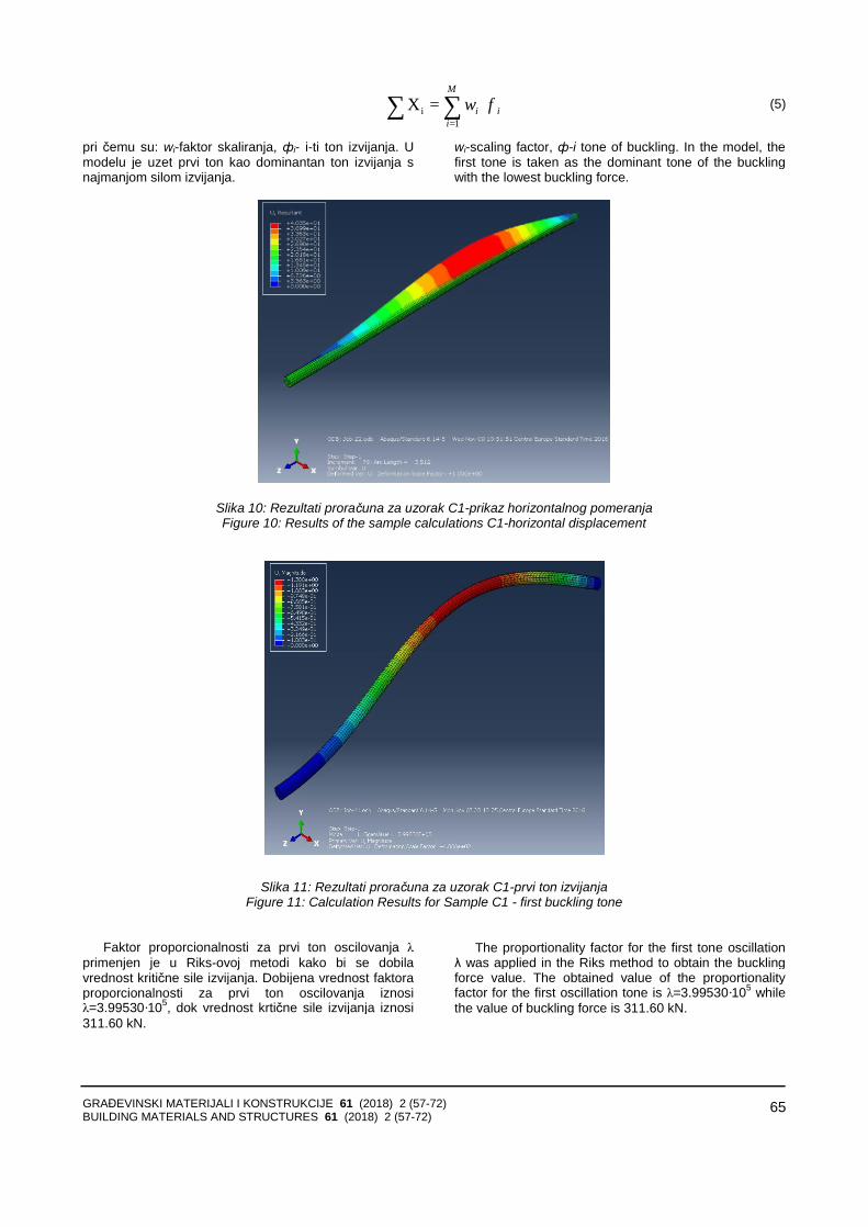
Slika 7 prikazuje kritične varijable oštećenja,
sračunate na liniji granične nosivosti za skup pretpostavljenih početnih imperfekcija. Velike vrednosti kritičnih varijabli oštećenja pokazuju da su tankozidne konstrukcije veoma osetljive na početne imperfekcije, što je dobro poznata činjenica potvrđena eksperimentalno.
Fig. 7 shows the critical damage variables calculated at the line of limit load capacity for a set of assumed initial imperfections. Large values of critical damage variables show that the thin-walled structures are very sensitive to the initial imperfections, which is a well known fact proved experimentally.
0,79
0,795
0,8
0,805
0,81
0,815
0,82
0,825
0 0,5 1 1,5 2 2,5 3 3,5 4 4,5 5 5,5
a1 [mm]
Dcr
Slika 7. Uticaj početnih imperfekcija na kritičnu varijablu oštećenja
Fig. 7. Influence of initial imperfections on the critical damage variable
Varijabla oštećenja je najveća za imperfekciju a1 = 0.1 mm, dokazujući tako da su tankozidne konstrukcije osetljivije za manje početne imperfekcije. Ovaj zaključak u potpunosti je u skladu s ranijim zaključkom da se za ovu veličinu imperfekcije greda krto lomi, iako je napravljena od duktilnog materijala. Zanimljivo je napomenuti i to da u radu [5], Lemaitre tvrdi da varijabla oštećenja pri lomu elemenata u slučaju metala jeste u granicama 0 2 0 8cr. D .≤ ≤ .
Identifikacija parametara za slučaj merene imperfek-cije a1 = 1.5 mm daje
• Euler-ova kritična sila
Damage variable is the greatest for the imperfection a1 = 0.1 mm, thus proving that the thin-walled constructions more sensitive for the less initial imperfections. This conclusion is in full compliance with the earlier conclusion that for this size of imperfection beam brittle failures, although made of ductile material. It is interesting to note that in the paper [5], Lemaitre claimed that damage variable for breaking in the case of metal elements is within the limits 0 2 0 8cr. D .≤ ≤ .
Parameters identification for the case of the measured imperfection a1 = 1.5 mm gives
• Euler’s critical force
2 2
2 20
20600 42 38 149 60240
HE
E I .Q . kNl
π π ⋅ ⋅= = =
• Granična nosivost u tački C1, jednačina (25) i odgovarajući napon
• Ultimate carrying capacity at point C1, Eq. (25) and corresponding stress
1 122 53CQ . kN= , 211
0
122 53 17 816 88
CC
Q . . kN / cmA .
σ = = =
• Ugib u sredini dužine grede • Deflection in the mid-length of beam
11
1 5 8 29122 531 1149 6
c
E
a .v . mmQ .
Q .
= = =− −
GRAĐEVINSKI MATERIJALI I KONSTRUKCIJE 61 (2018) 2 (3-17) BUILDING MATERIALS AND STRUCTURES 61 (2018) 2 (3-17)
15
• Vitkost • Slenderness
1
1
206000 106 84178 10
HC
C
E.
.λ π π
σ= = =
• Koeficijent tečenja • Creep coefficient
32 2
11
1 10000 36076 4 247 86 106 84C
C
i . .I . .
ϕ π πγλ
= = ⋅ ⋅ =⋅ .
• Ugib u sredini dužine grede u prvoj iteraciji • Deflection in the mid-length of beam in the first
proračuni obavljeni primenom RDA pokazuju saglasnost s hipotezama mehanike oštećenja.
5 ZAKLJUČCI
U radu je teorijski istraživan komplikovan problem granične nosivosti tankozidne grede s početnim geometrijskim imperfekcijama, pod pretpostavkama elastičnosti, plastičnosti i primenom RDA. RDA je neelastična (viskoelastoplastična) teorija i obuhvata obe prethodno pomenute. Radi prezentovanja primenjivosti RDA, urađeno je poređenje s numeričkim i eksperimentalnim rezultatima jedne čelične grede iz literature [1] od Murray-a. Zavisno od polaznih pretpostavki o materijalu, pojam granične nosivosti varira i zbog toga nije moguće dati jedinstvenu formulaciju za graničnu nosivost.
Pojam granične nosivosti, pod pretpostavkama idealno elastičnog materijala na analiziranom primeru
Because that effective load capacity (capacity of
undamaged beam) ( )11CQ% is equal to the limit load
capacity QC1, calculations which are made by using the RDA are consistent with the hypothesis of damage mechanics.
5 CONCLUSINS
The paper was theoretically investigated the problem involved ultimate bearing capacity of thin-walled beam with initial geometrical imperfections under the conditions of elasticity, plasticity and using RDA. RDA is inelastic (viscoelastoplastic) theory and includes both previously mentioned. In order to present applications of RDA the comparison is done with the numerical and experimental results of a steel beam from the literature of Murray [1]. Depending on the assumptions about the material the concept of limit load capacity varies and is therefore not possible to give a unique formulation for the ultimate bearing capacity.
The term limit load capacity under the conditions of ideal elastic material in the case of analyzed beam with
GRAĐEVINSKI MATERIJALI I KONSTRUKCIJE 61 (2018) 2 (3-17) BUILDING MATERIALS AND STRUCTURES 61 (2018) 2 (3-17)
16
grede sa zadanim početnim imperfekcijama, pokazuje da granična nosivost konvergira ka kritičnoj Euler-ovoj sili. Konvergencija je sporija što je veća početna imperfekcija. Prema teoriji elastičnosti, nije moguće dobiti omekšavajuće efekte pri opterećenjima bliskim kritičnom, koji se uočavaju eksperimentalno. Međutim, ključna mana ovog modela jeste to što u punom smislu reči elastičan materijal ne postoji, odnosno on je samo hipotetički zamišljen.
Pojam granične nosivosti pod pretpostavkom idealne plastičnosti daje u analiziranom primeru gornju graničnu nosivost. Ova teorija opisuje omekšavajuće efekte, jer daje manju graničnu nosivost pri većim početnim imperfekcijama. Ključna mana ovog modela jeste to što ne objašnjava kritične napone pri izvijanju.
Granična nosivost, dobijena primenom RDA, uvek se nalazi između goreopisanih teorija. RDA teorija opisuje kritične napone pri neelastičnom izvijanju. Razlog za to jeste to što RDA uključuje neelastična svojstvamaterijala pri analizi izvijanja. U ovom radu, analizirano je samo kvazistatičko rešenje, δ → 0 ( DTσ σδ ω ω ω= = ), tako da su očekivani i dopunski neistraženi efekti koje RDA teorija daje u problemu dinamičke stabilnosti pod uticajem frekvencije
σω (frekvencija sile). RDA transformiše materijalno-nelinearan problem u linearno-dinamički problem, tako da su dobijena rešenja analitička.
Osim toga, RDA na efikasan način daje objašnjenja i u postkritičnom ponašanju analizirane grede, gde pokazuje da se greda izrađena od duktilnog materijala može lomiti od krtog do izrazito duktilnog ponašanja, zavisno od zadate početne imperfekcije. Iako je ovo odavno utvrđeno eksperimentalno, u ovom radu se to i teorijski potvrđuje. Kako je postkritično stanje u domenu mehanike oštećenja i nelinearne mehanike loma, RDA je upešna u poređenju s mehanikom oštećenja preko kritične varijable oštećenja.
Zahvalnost
Ovaj rad predstavlja deo istraživanja koja se sprovode u okviru istraživačkih projekata OI 174027 „Računarska mehanika u građevinskom inženjerstvu” i TR 36017 „Istraživanje mogućnosti primene otpadnih i recikliranih materijala u betonskim kompozitima, sa ocenom uticaja na životnu sredinu, u cilju promocije održivog građevinarstva u Srbiji”, uz podršku Ministarstva za nauku i tehnologiju Republike Srbije.
initial imperfections shows that the limit load capacity converging to the Euler-critical force. Convergence is slower for the larger the initial imperfections. According to the theory of elasticity the softening effects that observed experimentally under the load close to the critical load can not be obtained. However, the key disadvantage of this model is that in the full sense of the word elastic material does not exist, or it is only hypothetical thought.
The term limit load capacity under the assumption of ideal plasticity provides in the analyzed beam an upper limit load capacity. This theory describes softening effects, since it gives a lower limit load capacity at higher initial imperfections. The key disadvantage of this model is that it does not explain the critical buckling stresses.
The limit load capacity obtained by RDA is always located between the above-described theories. RDA theory describes the critical stresses for inelastic buckling. The reason is that RDA involves inelastic properties of materials in the analysis of buckling. In this paper the quasi-static solution is analyzed only, δ → 0 ( DTσ σδ ω ω ω= = ), so that the expected additional unexplored effects that RDA theory provides in the problem of dynamic stability under the influence of frequency σω (frequency of force). RDA transformed materially nonlinear problem into the linear dynamic problem so that the obtained analytical solutions.
Apart from this, RDA effectively provides explana-tions in post-critical behavior of the analyzed beam, which show that a beam made from ductile material can break from brittle to extremely ductile, depending on the initial imperfections. Although this a long time established experimentally in this paper is theoretically confirmed. Because that post-critical state is in the field of damage mechanics and nonlinear fracture mechanics, the RDA is successful compared with damage mechanics through the critical variables of damage.
Acknowledgements
The work presented in this paper is a part of the investigation conducted within the research projects OI 174027 "Computational Mechanics in Structural Engine-ering" and TR 36017 "Utilization of by-products and recycled waste materials in concrete composites for sustainable construction development in Serbia: investigation and environmental assessment of possible applications", supported by the Ministry of Science and Technology, Republic of Serbia. This support is gratefully acknowledged.
GRAĐEVINSKI MATERIJALI I KONSTRUKCIJE 61 (2018) 2 (3-17) BUILDING MATERIALS AND STRUCTURES 61 (2018) 2 (3-17)
17
6 LITERATURA REFERENCES
[1] Murray, N. W., Introduction to the Theory of Thin-Walled Structures, Oxford, Oxford University Press, 1984.
[2] Milašinović, D.D., Geometric non-linear analysis of thin plate structures using the harmonic coupled finite strip method. Thin-Walled Structures, 49(2), 280–290, 2011.
[3] Milašinović, D.D., Rheological-dynamical continu-um damage model for concrete under uniaxial compression and its experimental verification, Theoretical and Applied Mechanics, 42(2), 73–110, 2015.
[4] Milašinović, D. D., Rheological-dynamical analogy: prediction of buckling curves of columns. International Journal of Solids and Structures, 37(29), 3965–4004, 2000.
[5] Lemaitre, J., How to Use Damage Mechanics,
Nuclear Engineering and Design, 80, 233–245, 1984.
[6] Chan. S. L., Chui, P. P. T., A generalized design-based elasto-plastic analysis of steel frames by section assemblage concept, Journal of Engineering Structures, 19(8), 628–636, 1997.
[7] Milašinović, D. D., Thermo-visco-plasticity and creep in structural-material response of folded-plate structures, Building Materials and Structures, 60 (2017) 4 (7-15).
REZIME
GRANIČNA NOSIVOST PRITISNUTE GREDE SA IMPERFEKCIJAMA
Dragan D. MILAŠINOVIĆ Smilja ŽIVKOVIĆ
Ovaj rad predstavlja teorijsko istraživanje elastičnog i
neelastičnog izvijanja tankozidne grede s početnim imperfekcijama. Glavni cilj rada jeste da pokaže da lom grede varira od krtog do izrazito duktilnog – u zavisnosti od imperfekcija. Elastično rešenje za procenu uticaja imperfekcija na graničnu nosivost u elastičnom području dobro je poznato. Međutim, elastično rešenje može biti primenjeno samo do linije granične nosivosti. Istraži-vanje granične nosivosti konstrukcije veoma je komplikovan problem materijalne nelinearnosti, jer ovaj problem mora da uključi plastični mehanizam loma. U ovom radu analizirana je granična nosivost grede primenom reološko-dinamičke analogije (RDA) [4]. Radi prezentovanja mogućnosti RDA, urađeno je poređenje snumeričkim i eksperimentalnim rezultatima jedne čelične grede iz literature [1] od Murray-a.
LIMIT LOAD CAPACITY OF COMPRESSED BEAM WITH IMPERFECTIONS
Dragan D. MILASINOVIC Smilja ZIVKOVIC
This paper presents a theoretical investigation of
elastic and inelastic buckling of thin-walled beam with initial imperfections. The main aim of this paper is to show that the fracture of beams varies from brittle to extremely ductile depending on the imperfections. Elastic solution for estimation of intial imperfections against the limit load capacity in the elastic range is well known. However, the elastic solution can be applied only to the line of limit load capacity. Examination of the limit load capacity of structure is very complicate problem of material non-linearity, because this problem must includes the plastic mechanism of failure. In this paper the limit load capacity of beam is analyzed using the reological-dynamical analogy (RDA) [4]. In order to demonstrate the ability of RDA, the comparison with experimental and numerical results of one steel beam from Ref [1] by Murray, is done.
GRAĐEVINSKI MATERIJALI I KONSTRUKCIJE 61 (2018) 2 (3-17) BUILDING MATERIALS AND STRUCTURES 61 (2018) 2 (3-17)
18
GRAĐEVINSKI MATERIJALI I KONSTRUKCIJE 61 (2018) 2 (19-34) BUILDING MATERIALS AND STRUCTURES 61 (2018) 2 (19-34)
19
ŽELEZNIČKI MOSTOVI NA INTEROPERABILNIM PRUGAMA - ASPEKT INTERAKCIJE KOLOSEK/MOST
RAILWAY BRIDGES ON INTEROPERABLE LINES - ASPECT OF TRACK/BRIDGE
INTERACTION Nikola MIRKOVIĆ Zdenka POPOVIĆ Luka LAZAREVIĆ Milica VILOTIJEVIĆ Aleksandra MILOSAVLJEVIĆ
PREGLEDNI RAD REVIEW PAPER
UDK: 624.21.046:625.14doi:10.5937/GRMK1802019M
1 UVOD
Stabilnost mostova (novih i postojećih) i nasipa pod saobraćajnim opterećenjem pripada osnovnim parame-trima podsistema za infrastrukturu i treba da ispunjava osnovne zahteve definisane u „Tehničkim specifika-cijama interoperabilnosti koje se odnose na podsistem za infrastrukturu” (INF TSI) [6].
Mostovi se projektuju tako da mogu da prihvate vertikalno opterećenje u skladu sa šemama opterećenja, definisanim u [2]: šema opterećenja 71 i šema optere-ćenja SW. Pomenute šeme opterećenja treba pomnožiti faktorom alfa (α) kako je definisano u [2]. Minimalna vrednost faktora α za projektovanje novih mostova propisana je u [6].
Dinamička analiza zahteva se za mostove za maksimalne brzine preko 200 km/h [2, 6]. Pri projekto-vanju mostova treba uzeti u obzir sledeće uticaje [2, 6]:
Nikola Mirković, asistent - student doktorskih studija, Univerzitet u Beogradu, Građevinski fakultet, Bulevar kralja Aleksandra 73, 11000 Beograd, [email protected] dr Zdenka Popović, redovni profesor, Univerzitet u Beogradu, Građevinski fakultet, Bulevar kralja Aleksandra 73, 11000 Beograd, [email protected] dr Luka Lazarević, docent, Univerzitet u Beogradu, Građevinski fakultet, Bulevar kralja Aleksandra 73, 11000 Beograd, [email protected] Milica Vilotijević, asistent - student doktorskih studija, Univerzitet u Beogradu, Građevinski fakultet, Bulevar kralja Aleksandra 73, 11000 Beograd, [email protected] Aleksandra Milosavljević, student master studija, Univerzitet u Beogradu, Građevinski fakultet, Bulevar kralja Aleksandra 73, 11000 Beograd, [email protected]
1 INTRODUCTION
Resistance of bridges (new and existing) and earthworks to traffic load belong to basic parameters of the infrastructure subsystem and should meet the essential requirements defined in ’’The technical specifications for interoperability relating to the infrastructure subsystem’’ (INF TSI) [6].
Bridges shall be designed to support vertical loads in accordance with the load models, defined in [2]: Load Model 71 and Load Model SW. The mentioned load models shall be multiplied by the factor alpha (α) as defined in [2]. The minimal values of factor α for the design of new bridges are prescribed in [6].
Dynamic analysis is required for bridges designed for max. speeds over 200 km/h [2, 6]. In the design of bridge structure the following should be taken into account [2, 6]:
Nikola Mirkovic, teaching assistant - PhD student, Univer-sity of Belgrade, Faculty of Civil Engineering, Bulevar kralja Aleksandra 73, 11000 Belgrade, [email protected] dr Zdenka Popovic, professor, University of Belgrade, Faculty of Civil Engineering, Bulevar kralja Aleksandra 73, 11000 Belgrade, [email protected] dr Luka Lazarevic, assistant professor, University of Belgrade, Faculty of Civil Engineering, Bulevar kralja Aleksandra 73, 11000 Belgrade, [email protected] Milica Vilotijevic, teaching assistant - PhD student, Univer-sity of Belgrade, Faculty of Civil Engineering, Bulevar kralja Aleksandra 73, 11000 Belgrade, [email protected] Aleksandra Milosavljevic, MSc student, University of Bel-grade, Faculty of Civil Engineering, Bulevar kralja Aleksan-dra 73, 11000 Belgrade, [email protected]
GRAĐEVINSKI MATERIJALI I KONSTRUKCIJE 61 (2018) 2 (19-34) BUILDING MATERIALS AND STRUCTURES 61 (2018) 2 (19-34)
20
− centrifugalnu silu u slučaju koloseka koji je delom ili celom dužinom mosta u krivini,
− fiktivnu bočnu silu, − sile ubrzavanja i kočenja (podužne sile). Dodatno, pored uticaja od vozila (vertikalno
opterećenje, podužne sile ubrzavanja/kočenja, fiktivne bočne i centrifugalne sile), promena temperature u konstrukciji gornjeg stroja mosta značajno utiče na izbor statičkog sistema železničkog mosta. Svako pomeranje konstrukcije gornjeg stroja mosta izaziva pomeranje koloseka sa kontinualno zavarenim šinama i dodatne napone u šini. Interakcija kolosek/most zahteva međusobno usaglašavanje konstrukcije gornjeg stroja pruge, mosta i prelazne konstrukcije sa nasipa na most.
U ovom radu su razmatrani najvažniji parametri konstrukcije mosta (krutost oslonaca, dilataciona dužina i dužina raspona, kao i krutost na savijanje i visina konstrukcije gornjeg stroja mosta), koji utiču na interakciju kolosek/most. Pored toga, razmatran je otpor podužnom pomeranju koloseka sa kontinualno zavarenim šinama (otpor podužnom pomeranju šine u odnosu na prag i/ili otpor podužnom pomeranju praga kroz zastor).
Cilj rada je harmonizacija tehničkih zahteva za projektovanje i održavanje železničkih mostova na interoperabilnim prugama kako bi se ostvario slobodan protok putnika i tereta uz korišćenje železničkog saobraćaja.
2 OKVIR ZA TEHNIČKU REGULATIVU - TRENUTNO STANJE
Osnovni dokument koji definiše zahteve za železničke mostove jeste INF TSI [6]. U UIC objavama [8-11] date su preporuke za razmatranje interakcije vozilo/kolosek/most. One predstavljaju osnovu za razvoj EN standarda. Pomenute UIC objave definisale su modele statičkog opterećenja koje treba uzeti u razmatranje pri projektovanju železničkih mostova i dale su preporuke za proračune zasnovane na interakciji između vozila, koloseka i konstrukcije mosta.
Merodavni evrokodovi za mostove prikazani su u tabeli 1. Harmonizacija ovih evrokodova je deklarisani cilj Evropske komisije sa ciljem slobodnog toka železničkog saobraćaja. Posebno značajan za železničke mostove je EN 1991-2 [2] koji definiše opterećenja na mostovima.
− centrifugal force in the case of curved track over the whole or part of the bridge length,
− nosing force (frictional lateral force), and − acceleration and breaking forces (longitudinal
forces). In addition, influence of the vehicles (vertical loads,
longitudinal acceleration/breaking forces, lateral nosing and centrifugal forces), and temperature changes in bridge deck significantly affect the choice of railway bridge system. Any movement of the bridge deck induces a movement of the CWR (continuous welded rail) track and an additional rail stresses. Track/bridge interaction requires a mutual harmonisation of track superstructure, bridge structure and transition structures for the bridge.
The most important parameters of the bridge structure (support stiffness, expansion and span length, as well as bending stiffness and height of the bridge deck), which influence track/bridge interaction, were considered in this paper. In addition, the longitudinal CWR track resistance (longitudinal slipping restraint and/or longitudinal displacement resistance of rail) was considered.
The goal of this paper is harmonisation of technicalrequirements for railway bridge design and maintenance on interoperable lines in order to achieve the free flow of passengers and freight with the use of rail transport.
2 THE FRAMEWORK FOR TECHNICAL REGULATIONS - STATE OF THE ART
The basic document that defines the requirements for the railway bridges is INF TSI [6]. UIC leaflets [8-11]provide recommendations for consideration of the vehicle/track/bridge interaction. These leaflets were the base for the development of EN standards, and they defined the static loading models to be taken into consideration for the railway bridge design and provided recommendations for calculations based on interaction between vehicle, track and bridge structure.
The relevant Eurocodes for railway bridges are presented in Table 1. The harmonisation of these Eurocodes is declared aim of the European Commission for the purpose of free traffic flow. Particularly important for railway bridges is the EN 1991-2 [2] which defines loads on bridges.
Tabela 1. Trenutno stanje referentnih srpskih standarda SRPS EN za mostove
Table 1. State of the art of relevant Serbian standards SRPS EN for bridges
Srpska oznaka (Serbian designation)
Naslov na srpskom (Title in Serbian)
Naslov na engleskom (Title in English)
SRPS EN 1990:2012 Evrokod - Osnove projektovanja konstrukcija Eurocode - Basis of structural design SRPS EN
Eurocode 3: Design of steel structures - Part 2: Steel bridges - National Annex
SRPS EN 1994-2:2012 Evrokod 4 - Projektovanje spregnutih
konstrukcija od čelika i betona - Deo 2: Opšta pravila i pravila za mostove
Eurocode 4 - Design of composite steel and concrete structures - Part 2: General
rules and rules for bridges
SRPS EN 1994-2/NA:2016
Evrokod 4 - Projektovanje spregnutih konstrukcija od čelika i betona - Deo 2: Opšta
pravila i pravila za mostove - Nacionalni prilog
Eurocode 4 - Design of composite steel and concrete structures - Part 2: General
rules and rules for bridges - National Annex
SRPS EN 1997-1:2017 Evrokod 7 - Geotehničko projektovanje - Deo 1: Opšta pravila
Eurocode 7: Geotechnical design - Part 1: General rules
SRPS EN 1997-2:2014 Evrokod 7 - Geotehničko projektovanje - Deo 2: Istraživanje tla i ispitivanje
Eurocode 7 - Geotechnical design - Part 2: Ground investigation and testing
SRPS EN 1998-1:2015 Evrokod 8 - Projektovanje seizmički otpornih
konstrukcija - Deo 1: Opšta pravila, seizmička dejstva i pravila za zgrade
Eurocode 8: Design of structures for earthquake resistance - Part 1: General
rules, seismic actions and rules for buildings
SRPS EN 1998-2:2012 Evrokod 8 - Projektovanje seizmički otpornih konstrukcija - Deo 2: Mostovi
Eurocode 8: Design of structures for earthquake resistance - Part 2: Bridges
3 PARAMETRI KONSTRUKCIJE MOSTA
Interakcija vozila, koloseka i mosta igra značajnu ulogu u projektovanju i održavanju železničkih mostova.
Zbog sila od vozila (vertikalno opterećenje, podužne sile pri pokretanju i kočenju vozila), kao i temperaturnih promena i dilatacija mosta, pojaviće se uticaji u konstrukciji gornjeg stroja železničke pruge, a naročito u šinama. Upravljanje interakcijom vozilo/kolosek/most zahteva odgovarajuće postupke proračuna koji odgovaraju konstrukciji i dužini mosta.
3 PARAMETERS OF THE BRIDGE STRUCTURE
Interaction of vehicle/track/bridge plays a key role in design and maintenance of railway bridges.
Forces induced by the vehicles (vertical load and longitudinal forces during acceleration/breaking of the vehicles), as well as temperature changes and bridge displacement affect track superstructure, especially the rails. Control of the vehicle/track/bridge interaction requires appropriate calculations that correspond to the structure and length of the bridge.
U daljem tekstu će se predstaviti parametri Parameters of the track/bridge interaction, the
GRAĐEVINSKI MATERIJALI I KONSTRUKCIJE 61 (2018) 2 (19-34) BUILDING MATERIALS AND STRUCTURES 61 (2018) 2 (19-34)
22
interakcije kolosek/most, principi proračuna, kao i pregled otvorenih pitanja.
3.1 Dužine dilatiranja mosta
Dužine dilatiranja mosta zavise od statičkog sistema i raspona mosta. Prema UIC Code 774-3 [9] utvrđene su maksimalne dilatacione dužine mostova sa jednim kolosekom i više koloseka u zastoru od tucanika ili na čvrstoj podlozi sa kontinualno zavarenim šinama:
− 60 m za čelične mostove, − 90 m za betonske i spregnute mostove. Propisana maksimalna dilataciona dužina čeličnih
železničkih mostova veća je od dilatacionih dužina betonskih i spregnutih konstrukcija mostova zato što čelični mostovi imaju izraženiji odziv na promenu temperature u konstrukciji gornjeg stroja mosta.
U tabeli 2 prikazane su merodavne temperature za čelične, spregnute i betonske konstrukcije mostova na nemačkim železnicama prema [4].
principles of the calculation, as well as the overview of open points will be presented in the following part of the paper.
3.1 Bridge expansion lengths
Bridge expansion lengths depend on the static system and the bridge span. According to UIC Code 774-3 [9], maximum bridge expansion lengths with one or more tracks, either ballasted or slab track, with continuously welded rails are determined:
− 60 m for steel bridges, − 90 m for concrete and composite bridge
structures. Recommended maximum expansion length of the
steel rail bridges is greater than the expansion lengths of the concrete and composite bridge structures because the steel bridges have greater response to the temperature change in the bridge deck. Table 2 shows the representative temperatures for the steel, composite and concrete bridge structures on German railways according to [4].
Tabela 2. Temperaturna promena u zavisnosti od vrste konstrukcije mosta
Table 2. Temperature change depending on the type of bridge structure
Note: The neutral temperature of the bridge, at which the bearings are installed, is 10°C according to [4]. The value of neutral temperature is determined by the Infrastructure Manager.
(Napomena: Neutralna temperatura mosta, pri kojoj se ugrađuju ležišta, je 10oC prema [4].Vrednost neutralne temperature utvrđuje Upravljač infrastrukture).
Na slici 1 dat je dijagram temperatura u gornjem stroju mosta na osnovu spoljne temperature prema [4]. Temperature predstavljene u tabeli 2 određene su iz dijagrama sa slike 1 unošenjem ekstremnih spoljnih temperatura -24oC i +37oC prema [5]. Pored toga, na dijagramu (slika 1) predstavljene su temperature u gornjem stroju mosta prema [16]. Naime, prema članu 43 pravilnika [16] ekstremne temperature mosta na železnicama Srbije jesu -25 oC i +45oC. Prema [16]neutralna temperatura za most je to=tsr=0,5·(45-25)=10oC (isto kao prema [4]). Može se zaključiti da temperature propisane u [16] zadovoljavaju ekstremne spoljne temperature -32oC i +45oC u slučaju betonskih mostova. Prema [17] izmereni temperaturni ekstremi u Srbiji su:
− najviša temperatura od +44,9оC (izmerena je 24.07.2007. godine u Smederevskoj Palanci),
− najniža temperatura od -39,0оC (izmerena je 26.01.2006. godine u Karajukića Bunarima na Pešterskoj visoravni).
Figure 1 shows a temperature diagram in the bridge deck based on air temperature according to [4]. The temperatures presented in Table 2 were determined using the diagram in Figure 1 by considering extreme air temperatures -24oC and +37oC according to [5]. In addition, the diagram in Figure 1 represents the temperatures in the bridge deck as defined in [16]. According to article 43 in [16], extreme bridge temperatures on the Serbian railways are -25oC and +45oC, and neutral temperature for the bridge is to = tsr = 0.5(45-25) = 10oC (the same as in [4]). It can be concluded that the temperatures given in [16] meet the extreme air temperatures in Serbia, which equal -32 oC and +45oC in the case of concrete bridges. According to [17] measured extreme temperatures in Serbia are:
− the highest temperature of +44,9 °C (measured on July 24, 2007 in Smederevska Palanka),
− the lowest temperature of -39,0 °C (measured on January 26, 2006 in Karajukić Bunari on Pešterska visoravan).
GRAĐEVINSKI MATERIJALI I KONSTRUKCIJE 61 (2018) 2 (19-34) BUILDING MATERIALS AND STRUCTURES 61 (2018) 2 (19-34)
23
Slika 1. Temperatura u konstrukciji gornjeg stroja mosta u zavisnosti od temperature vazduha (isprekidanom linijom su predstavljene temperature u Srbiji) [4]
Figure 1. Temperature in the bridge deck depending on the air temperature (dashed line presented the temperature in Serbia) [4]
U tabeli 3 date su vrednosti dilatacionih dužina mostova prema [16]. Odnos dilatacionih dužina koje se preporučuju u [4, 9] i „Pravilniku za železničke mostove u Srbiji” [16] jeste:
− za betonske mostove 90 m/60 m=1,5, − za čelične mostove 60 m/40 m=1,5.
Table 3 gives the values of bridge expansion lengths according to [16]. The ratio of expansion lengths recommended by [4, 9] and the ’’Regulations for Serbian railway bridges’’ [16] are:
− for concrete bridges 90 m /60 m = 1.5, − for steel bridges 60 m /40 m = 1.5.
Tabela 3. Maksimalne dilatacione dužine na mostovima u Srbiji prema [16] Table 3. Maximum expansion lengths of bridges in Serbia according to [14]
Track with continuous welded rails (Kolosek sa kontinualno zavarenim šinama)
Expansion length of bridge [m] (Dilataciona dužina mosta [m])
Necessary measures (Potrebne mere)
Steel and composite bridges: ≤ 40 m (Čelični i spregnuti mostovi: ≤ 40 m)
Concrete bridges: ≤ 60 m (Betonski mostovi: ≤ 60 m)
-
Steel and composite bridges: > 40 m (Čelični i spregnuti mostovi: > 40 m)
Ballasted track (Kolosek u zastoru od
tucanika)
Concrete bridges: > 60 m (Betonski mostovi: > 60 m)
Calculation of track / bridge interaction
(Proračun interakcije kolosek / most)
≤ 40 m for all types of bridges (≤ 40 m za sve tipove mostova) -
Slab track (Kolosek na čvrstoj
podlozi) > 40 m for all types of bridges (> 40 m za sve tipove mostova)
Calculation of track / bridge interaction
(Proračun interakcije kolosek / most)
GRAĐEVINSKI MATERIJALI I KONSTRUKCIJE 61 (2018) 2 (19-34) BUILDING MATERIALS AND STRUCTURES 61 (2018) 2 (19-34)
24
3.2 Krutost konstrukcije donjeg stroja mosta
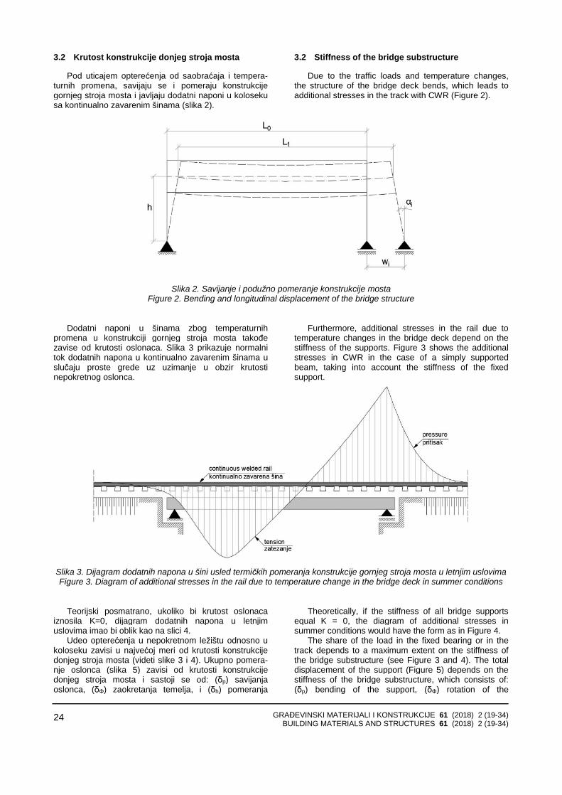
Pod uticajem opterećenja od saobraćaja i tempera-turnih promena, savijaju se i pomeraju konstrukcije gornjeg stroja mosta i javljaju dodatni naponi u koloseku sa kontinualno zavarenim šinama (slika 2).
3.2 Stiffness of the bridge substructure
Due to the traffic loads and temperature changes, the structure of the bridge deck bends, which leads to additional stresses in the track with CWR (Figure 2).
Slika 2. Savijanje i podužno pomeranje konstrukcije mosta Figure 2. Bending and longitudinal displacement of the bridge structure
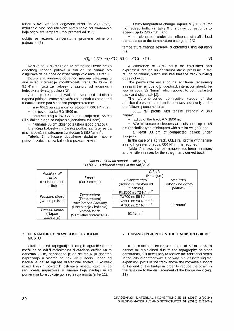
Dodatni naponi u šinama zbog temperaturnih promena u konstrukciji gornjeg stroja mosta takođe zavise od krutosti oslonaca. Slika 3 prikazuje normalni tok dodatnih napona u kontinualno zavarenim šinama u slučaju proste grede uz uzimanje u obzir krutosti nepokretnog oslonca.
Furthermore, additional stresses in the rail due to temperature changes in the bridge deck depend on the stiffness of the supports. Figure 3 shows the additional stresses in CWR in the case of a simply supported beam, taking into account the stiffness of the fixed support.
Slika 3. Dijagram dodatnih napona u šini usled termičkih pomeranja konstrukcije gornjeg stroja mosta u letnjim uslovima Figure 3. Diagram of additional stresses in the rail due to temperature change in the bridge deck in summer conditions
Teorijski posmatrano, ukoliko bi krutost oslonaca iznosila K=0, dijagram dodatnih napona u letnjim uslovima imao bi oblik kao na slici 4.
Udeo opterećenja u nepokretnom ležištu odnosno u koloseku zavisi u najvećoj meri od krutosti konstrukcije donjeg stroja mosta (videti slike 3 i 4). Ukupno pomera-nje oslonca (slika 5) zavisi od krutosti konstrukcije donjeg stroja mosta i sastoji se od: (δp) savijanja oslonca, (δΦ) zaokretanja temelja, i (δh) pomeranja
Theoretically, if the stiffness of all bridge supports equal K = 0, the diagram of additional stresses in summer conditions would have the form as in Figure 4.
The share of the load in the fixed bearing or in the track depends to a maximum extent on the stiffness of the bridge substructure (see Figure 3 and 4). The total displacement of the support (Figure 5) depends on the stiffness of the bridge substructure, which consists of: (δp) bending of the support, (δΦ) rotation of the
GRAĐEVINSKI MATERIJALI I KONSTRUKCIJE 61 (2018) 2 (19-34) BUILDING MATERIALS AND STRUCTURES 61 (2018) 2 (19-34)
25
temelja. Podužna krutost oslonca se može odrediti kao količnik podužne reakcije F1 i ukupne krutosti.
foundation, and (δh) displacement of the foundation. The longitudinal stiffness of the support can be determined as the quotient of the longitudinal reaction F1 and total stiffness.
Slika 4. Dijagram dodatnih napona u šini usled termičkih pomeranja konstrukcije gornjeg stroja mosta u letnjim uslovima
za krutost oslonaca K=0 Figure 4 Diagram of additional stresses in the rail due to temperature change in the bridge deck in summer conditions
for the supports stiffness K = 0
Slika 5. Pomeranja konstrukcije donjeg stroja mosta Figure 5. Displacement of the bridge substructure
3.3 Krutost na savijanje i visina konstrukcije
gornjeg stroja mosta
Dodatna naprezanja šine mogu da nastanu usled: − sila koje deluju u podužnom pravcu, − vertikalnog opterećenja koje izaziva pomeranje
krajeva usled savijanja konstrukcije gornjeg stroja mosta (slika 6).
Rezultujuće podužno pomeranje na kraju sa pokretnim osloncem (slika 6 levo) određuje se kao razlika pomeranja usled savijanja (ΔSLM71) i podužnog pomeranja oslonaca (ΔSHLM71 ).
3.3 Bending stiffness and height of the bridge deck
Additional stress in rails may occur due to: − longitudinal forces, − the vertical load causing the displacement of the
bridge deck ends due to the bending (Figure 6). In the case of movable support, the resulting
longitudinal displacement at the end (Figure 6 on the left) is determined as the difference of displacement due to the bending (ΔSLM71) and longitudinal displacement of the supports (ΔSHLM71).
Vertical displacement due to the rotation of the ends Vertikalno pomeranje zbog zaokretanja krajeva
gornjeg stroja mosta usled uticaja od saobraćaja zavisi od dužine prepusta ”u” iza ose oslonca (slika 6 desno, tabela 4). To je od naročitog značaja u slučaju velikih visina konstrukcije gornjeg stroja mosta, npr. kod sandučastih konstrukcija. U takvim slučajevima, treba da se izabere što manji prepust preko oslonca.
of bridge deck under the traffic influence depends on the length of the overhang "u" behind the axis of the support (Fig. 6 right, Table 4). This is of particular relevance in the case of large height of the structure of the bridge deck, e.g. bridges with box cross sections. In such cases, the overhang "u" should be designed to be as least as possible.
GRAĐEVINSKI MATERIJALI I KONSTRUKCIJE 61 (2018) 2 (19-34) BUILDING MATERIALS AND STRUCTURES 61 (2018) 2 (19-34)
26
Slika 6. Podužna i vertikalna pomeranja na krajevima konstrukcije gornjeg stroja mosta [7]
Figure 6. Longitudinal and vertical displacement at the ends of the bridge deck [7]
Tabela 4. Granične vrednosti pomeranja kraja konstrukcije gornjeg stroja mosta usled vertikalnog opterećanja od saobraćaja [7]
Table 4. Limit values of displacement of the end of the bridge deck due to vertical load from traffic [7]
Limit value of deformation on overhang due to traffic load (Granična vrednost deformacije na prepustu usled saobraćajnog opterećenja)
End span length (Raspon krajnjeg polja)
Design speed V (Projektna brzina V)
Limit value δ (Granična vrednost δ)
V ≤ 160 km/h δ= 5 mm 160 km/h < V < 230 km/h δ= 4 mm ≤ 3 m
V > 230 km/h δ= 3 mm ≥ 25 m for all (za sve) V δ= 9 mm
3 m < L < 25 m Intermediate values are obtained by linear interpolation (Međuvrednosti se dobijaju linearnom interpolacijom)
4 OTPOR PODUŽNOM POMERANJU KOLOSEKA
SA KONTINUALNO ZAVARENIM ŠINAMA
Ponašanje koloseka u podužnom pravcu razmatra se kao otpor podužnom pomeranju konstrukcije koloseka (u zastoru od tucanika) i otpor klizanju šine po pričvršćenju (merodavan u zimskim uslovima kada je tucanik u zastornoj prizmi smrznut i u slučaju koloseka na čvrstoj podlozi). Tok pomeranja je nelinearan, ali se za prak-tičnu upotrebu uproščuje bilinearnom funkcijom (slika 7). Vrednost otpora zavisi od toga da li je kolosek opterećen ili neopterećen.
4 LONGITUDINAL RESISTANCE OF THE TRACK WITH CONTINUOUS WELDED RAIL
Behaviour of the track in the longitudinal direction is considered as a resistance to the longitudinal displace-ment of the track structure (in the ballasted track) and the resistance to the rail slipping over fastening system ( applicable for winter conditions when the ballast is frozen, as well as in the case of slab track). Displace-ment is non-linear, but for practical use it is simplified to the bilinear function (Figure 7). The resistance value depends on whether the track is loaded or unloaded.
Slika 7. Otpori podužnom pomeranju koloseka/šine Figure 7. Longitudinal resistance to the displacement of the track/rail
GRAĐEVINSKI MATERIJALI I KONSTRUKCIJE 61 (2018) 2 (19-34) BUILDING MATERIALS AND STRUCTURES 61 (2018) 2 (19-34)
27
Prema INF TSI (tačka 4.2.6.1 u [6]) sistem šinskog pričvršćenja odgovara zahtevu „Stabilnost koloseka pod vertikalnim opterećenjem”. Sistem šinskih pričvršćenja ispituje se u laboratorijskim uslovima prema EN 13146-1 i treba da zadovolji sledeće zahteve: podužna sila pri elastičnom pomeranju šine u sistemu šinskog pričvršćenja mora da bude najmanje 7 kN, a na prugama za brzine veće od 250 km/h mora da bude najmanje 9 kN. Ukoliko je potrebno, dopušteno je smanjenje podužnog otpora sistema šinskog pričvršćenja na mostu radi smanjenja sile pritiska u šini u zoni krajnjeg pokretnog oslonca (uključujući sisteme koji ne pružaju otpor podužnom pomeranju šine, npr. PANDROL® ZRL -Zero Longitudinal Restraint).
5 UTICAJI KOČENJA I UBRZAVANJA VOZILA NA MOSTU
Sile od kočenje i ubrzavanja vozila deluju na
konstrukciju koloseka i konstrukciju gornjeg stroja mosta. One imaju kratkotrajni uticaj za razliku od sila usled temperaturnih promena.
Sile od kočenja i ubrzavanja vozila su ograničene na osnovu maksimalnog raspoloživog trenja u dodiru točak/šina (čelik po čeliku). Iza vozila koje koči nastaju naponi zatezanja, dok ispred vozila koje koči nastaju naponi pritiska u šini (slika 8).
According to INF TSI (point 4.2.6.1 in [6]), the rail fastening system is relevant to the requirements for ”Track resistance under vertical loads”. The rail fastening system should comply with laboratory test conditions, prescribed in EN 13146-1, with the following require-ment: the longitudinal force required to cause the rail to begin slipping (i.e. move in an inelastic way) over a single rail fastening assembly shall be at least 7 kN, but for speeds higher than 250 km/h should be at least 9 kN. If necessary, it is permissible to reduce the longitudinal resistance of the rail fastening system on the bridge in order to reduce the pressure in the rail around moving support at the bridge end (including systems that fail to provide resistance to the longitudinal movement of the rail, e.g. PANDROL® ZRL - Zero Longitudinal Restraint).
5 THE EFFECTS OF BREAKING AND ACCELERATION OF THE VEHICLE ON THE BRIDGE
The breaking and acceleration forces from the vehicle act on the track structure and the bridge deck. They have a short-term effect as opposed to the forces due to temperature changes.
The breaking and acceleration forces from the vehicle are limited with the maximum available friction in the wheel/rail contact (steel on steel). Behind the breaking vehicle, tensioning stress occurs. On the other hand, the pressure stress in the rail is generated in front of the vehicle (Figure 8).
Slika 8. Dijagram napona u šini usled kočenja voza Figure 8. The diagram of the stress in the rail due to the braking of the train
Na slici 9 prikazano je horizontalno opterećenje koloseka usled kočenja i ubrzavanja vozila. Poređenja radi, prikazan je dijagram sila kočenja za drumski most.
Frikcione kočnice železničkih vozila deluju na osnovu trenja, koje se u većini slučajeva postiže korišćenjem komprimovanog vazduha. Kada mašinovođa aktivira kočnicu, talas vazdušnog pritiska napreduje brzinom 250–280 m/s. Dakle, vozilo koči sa zadrškom –takozvano vreme pripreme kočenja. Odloženo vreme delovanja kočnice, naročito u slučaju dugačkih sastava, dovodi do pojave podužnih dinamičkih sila. Ove sile su posledica nesimultanog kočenja pojedinačnih kola, što dovodi do pojave sila pritiska između njih.
Trzaj pri kočenju koji nastaje kratko pre zaustavljanja
Figure 9 shows the horizontal load of the track under breaking and acceleration of the vehicle. For the comparison, breaking forces for the road bridge are pesented.
Frictional brakes on railway vehicles operate on the basis of friction, which is in most cases achieved using compressed air. When the brake is activated by the machine operator, the airflow wave progresses with speed of 250-280 m/s. Therefore, breaking the vehicle is applied with a delay - after so-called brake preparation time. Break delay time, especially in the case of long railway vehicles, leads to the occurrence of longitudinal dynamic forces. These forces are the consequence of non-simultaneous breaking of individual railcars, which
GRAĐEVINSKI MATERIJALI I KONSTRUKCIJE 61 (2018) 2 (19-34) BUILDING MATERIALS AND STRUCTURES 61 (2018) 2 (19-34)
28
voza, merodavan je za dimenzionisanje železničkih mostova [7]. Najveći trzaj pri kočenju javlja se pod teretnim vozovima zbog velike sopstvene težine.
generates the pressure forces between them. Jerk during breaking that occurs shortly before
stopping the train is representative for the design of railway bridges [7]. The largest jerk during breaking occurs under freight trains due to their large weights.
Slika 9. Horizontalne podužne sile od kočenja i ubrzavanja vozila [12]
Figure 9. Horizontal longitudinal forces from breaking and acceleration of the vehicle [12]
U skladu sa [5, 9] utvrđene su maksimalne vrednosti sila pri ubrzanju i kočenju železničkih vozila:
− Sila pri ubrzavanju vozila QIak pri šemama opterećenja 71, SW/0, SW/2 i HSLM:
According to [5, 9], following maximum acceleration and breaking forces for railway vehicles have been determined:
− Acceleration force of vehicle QIak for load models 71, SW/0, SW/2 and HSLM:
QIak=33 kN/m * LIak [m] ≤ 1000 kN, (1)
− Sila kočenja pri šemama opterećenja 71, SW/0 i HSLM,
− Breaking force QIbk for load models 71, SW/0 and HSLM:
QIbk=20 kN/m * LIbk [m] ≤ 6000 kN, (2a)
odnosno pri šemi opterećenja SW/2: and for load model SW/2:
QIbk=35 kN/m * LIbk [m] (2b)
Maksimalna dužina uticaja LIbk bira se do 300 m kako bi se sprečila pojava sila kočenja koje su veće od 6000 kN (600 t). Štaviše, treba uzeti u obzir da dužina teških teretnih vozova (2000 t i više) ne prekoračuje 300 do 400 m u opštem slučaju, zbog ograničenja zatezanja kuke kvačila pri pokretanju vozila. Usled razvoja sistema kočenja i tehnologije prenosa može biti neophodno da se u proračunu koriste veći uticaji od kočenja u određenim okolnostima. Uobičajene vrednosti dužina uticaja i sila kočenja i ubrzavanja prikazane su u tabeli 5.
Maximum impact length LIbk should be up to 300 m in order to prevent occurrence of brake forces larger than 6000 kN (600 t). Furthermore, it should be taken into account that length of heavy freight trains (that weighs 20000 kN and more) do not exceed 300 m to 400 m in general, due to the limited stretching of the coupler at train start-up. Due to the development of breaking and transmission technologies, it would be necessary to ac-count larger impact of breaking under certain circum-stances. The usual values of the impact lengths and the
U proračunu se koristi sigurnosna temperaturna razlika ΔTs kako bi se uzela u obzir odstupanja uticaja usled:
− sila kočenja, − sila završnog pritezanja koje deluje na nožicu
kontinualno zavarenih šina, − bočnih sila. Sigurnosna temperaturna razlika treba da osigura
stabilnost koloseka od bočnog izbacivanja. U tabeli 6 prikazane su vrednosti ΔTs u zavisnosti od brzine vožnje
breaking and acceleration forces are shown in Table 5. Safety temperature difference ΔTs is used in cal-
culation in order to take into account the uncertainty of: − breaking forces, − final clamping forces applied to the foot of
continuous welded rails, and − lateral forces. The safety temperature difference should ensure the
stability of the track from buckling. Table 6 shows the values of ΔTs depending on the driving speed [7]. In
GRAĐEVINSKI MATERIJALI I KONSTRUKCIJE 61 (2018) 2 (19-34) BUILDING MATERIALS AND STRUCTURES 61 (2018) 2 (19-34)
29
[7]. Takođe, vrednosti ΔTs u tabeli 6 obuhvataju i uticaj elektromagnetne kočnice koja je ugrađena u vozilo ICE3 (slika 10).
addition, ΔTs values in Table 6 include the influence of the electromagnetic rail brakes that are installed on the ICE3 train (Figure 10).
Tabela 5. Karakteristike opterećenja od kočenja i ubrzavanja
Table 5. Parameters of breaking and acceleration load
Acceleration loads (Opterećenje od ubrzavanja)
Braking loads (Opterećenje od kočenja) Type of Track
(Tip koloseka) Magnitude of Load (Intenzitet opterećenja)
Loaded length (Dužina
opterećenja)
Magnitude of Load (Intenzitet opterećenja)
Loaded length (Dužina
opterećenja) High-speed railway
(Pruga za velike brzine)
33 kN/m/track 33 kN/m/kolosek 33 m 20 kN/m/track
20 kN/m/kolosek 400 m
Normal railway (Konvencionalna
pruga)
24 kN/m/track 24 kN/m/kolosek 33 m 12 kN/m/track
12 kN/m/kolosek 300 m
Slika 10. Elektromagnetna kočnica za ICE3 vozilo Figure 10. Electromagnetic rail brake on the ICE3 train
Tabela 6. Sigurnosna temperaturna razlika ΔTs u zavisnosti od brzine vožnje [7] Table 6. Safety temperature difference ΔTs depending on the driving speed [7]
Dozvoljeni dodatni naponi pritiska u šini usled interakcije kolosek/most treba da budu [1, 4, 9]:
− ≤ 72 N/mm2 za kolosek u zastoru od tucanika, − ≤ 92 N/mm2 za kolosek na čvrstoj podlozi; Dokazivanje dopuštenog dodatnog napona pritiska
izvodi se na osnovu kriterijuma izbacivanja koloseka sa kontinualno zavarenim šinama.
Kritično povećanje temperature u šini koje može da dovede do izbacivanja koloseka iznosi cca. 122°Cprema [3, 13], pod sledećim pretpostavkama:
− greška u smeru koloseka 4,5 mm za pruge za velike brzine,
− dinamički otpor poprečnom pomeranju koloseka wQ=10 kN/m;
− kolosek sa šinama 60E1, betonski pragovi B70. Prema razmatranjima u radu [7], ukoliko se usvoji: − temperaturna promena 38°C između temperature
u šini i temperature pri završnom pritezanju kontinualno zavarene šine,
6 ADDITIONAL STRESSES IN THE RAIL
The permissible additional pressure in the rail due to the track/bridge interaction should be [1, 4, 9]:
− ≤ 72 N / mm2 for ballasted track, − ≤ 92 N / mm2 for a slab track. The permissible additional pressure should be
calculated using track buckling criteria for CWRs. The critical temperature increase in the rail, which can lead to track buckling, is approximately 122°C according to [3, 13] under the following assumptions:
− track alignment deviation equals 4,5 mm for high speed lines,
− dynamic resistance to the lateral displacement of the track wQ = 10 kN/m, and
− track with 60E1 rail profile and B70 concrete sleepers.
According to the discussions in [7], if following is adopted:
− temperature difference between rail temperature and temperature at the final tightening of CWR equals
− sigurnosna temperaturna promena ΔTs=50°C (u 38°C,
GRAĐEVINSKI MATERIJALI I KONSTRUKCIJE 61 (2018) 2 (19-34) BUILDING MATERIALS AND STRUCTURES 61 (2018) 2 (19-34)
30
tabeli 6 ova vrednost odgovara brzini do 230 km/h),izduženje šine pod uticajem opterećenja od saobraćaja koje odgovara temperaturnoj promeni od 3°C,
dobija se rezerva temperaturne promene primenom jednačine (3).
− safety temperature change equals ΔTs = 50°C for high speed traffic (in table 6 this value corresponds to speeds up to 230 km/h), and
− rail elongation under the influence of traffic load corresponds to the temperature change of 3°C,
temperature change reserve is obtained using equation (3).
C31C)3C50C(38C122ΔT oooooR =++−= (3)
Razlika od 31°C može da se proračuna i izrazi preko dodatnog napona pritiska u šini od 72 N/mm2 štoosigurava da ne dođe do izbacivanja koloseka u stranu.
Dozvoljena vrednost dodatnog napona zatezanja u šini usled interakcije most/kolosek treba da bude ≤ 92 N/mm2 (važi za kolosek u zastoru od tucanika i kolosek na čvrstoj podlozi) [2].
Gore pomenute dozvoljene vrednosti dodanih napona pritiska i zatezanja važe za kolosek u zastoru od tucanika samo pod sledećim pretpostavkama:
− šine 60E1 sa zateznom čvrstoćom ≥ 880 N/mm2; − radijus koloseka R ≥ 1500 m; − betonski pragovi B70 W na rastojanju max. 65 cm
(ili slični tip praga sa najmanje jednakom težinom); − najmanje 30 cm zbijenog zastora ispod pragova. U slučaju koloseka na čvrstoj podlozi zahteva se da
je šina 60E1 sa zateznom čvrstoćom ≥ 880 N/mm2 . Tabela 7. prikazuje dopuštene dodatne napone
pritiska i zatezanja za kolosek u pravcu i krivini.
A difference of 31°C could be calculated and expressed through an additional stress pressure in the rail of 72 N/mm2, which ensures that the track buckling does not occur.
The permissible value of the additional tensioning stress in the rail due to bridge/track interaction should be less or equal 92 N/mm2, which applies to both ballasted track and slab track [2].
The aforementioned permissible values of the additional pressure and tensile stresses apply only under the following assumptions:
− 60E1 rail profile with tensile strength ≥ 880 N/mm2,
− radius of the track R ≥ 1500 m, − B70 W concrete sleepers at a distance up to 65
cm (or similar type of sleepers with similar weight), and − at least 30 cm of compacted ballast under
sleepers. In the case of slab track, 60E1 rail profile with tensile
strength greater or equal 880 N/mm2 is required. Table 7 shows the permissible additional stresses
and tensile stresses for the straight and curved track.
Tabela 7. Dodatni naponi u šini [2, 9] Table 7. Additional stress in the rail [2, 9]
Ukoliko usled topografije ili drugih ograničenja ne može da se održi maksimalna dilataciona dužina 60 m odnosno 90 m, neophodno je da se redukuju dodatna naprezanja u šinama na neki drugi način. Jedan od načina je da se ugrade dilatacione sprave u kolosek iznad krajnjih pokretnih oslonaca mosta, kako bi se redukovala naprezanja u šinama koja nastaju usled pomeranja konstrukcije gornjeg stroja mosta (slika 11).
7 EXPANSION JOINTS IN THE TRACK ON BRIDGE
If the maximum expansion length of 60 m or 90 m
cannot be maintained due to the topography or other constraints, it is necessary to reduce the additional strain in the rails in another way. One way implies installing the expansion joints in the track above the movable support at the end of the bridge in order to reduce the strain in the rails due to the displacement of the bridge deck (Fig. 11).
GRAĐEVINSKI MATERIJALI I KONSTRUKCIJE 61 (2018) 2 (19-34) BUILDING MATERIALS AND STRUCTURES 61 (2018) 2 (19-34)
31
Slika 11. Naprezanje u šini na (pokretnom) kraju mosta sa dilatacionom spravom u koloseku Figure 11. Strain in the rail at the movable end of the bridge with rail expansion joint
Ipak, dilatacione sprave treba izbegavati zbog: − velike cene proizvodnje i ugradnje, − velikih troškova održavanja, − nepovoljnog uticaja na komfor vožnje. Slika 12 prikazuje diskontinuitet na voznoj površi na
glavi šine u zoni dilatacione sprave.
However, rail expansion joints should be omitted due to:
− high price of production and installation, − high maintenance costs, and − adverse influence to the driving comfort. Figure 12 shows the discontinuity on the running
surface of the rail head in the zone of expansion joint.
Slika 12. Diskontinuitet vozne površi u zoni dilatacione sprave Figure 12. Discontinuity of the running surface of the rail head at the expansion joint
Kako bi se smanjila cena, dilatacione sprave su standardizovane prema dužini dilatiranja, kao što je prikazano u tabeli 8. U svakom slučaju, neophodno je obratiti posebnu pažnju na komplikovanu ugradnju i održavanje.
In order to reduce price, it is necessary to standardise expansion joints according to their expansion length as it is shown in Table 8. In any case, special attention should be drawn to the complicated installation and maintenance.
Tabela 8. Standardni tipovi dilatacionih sprava na železnici u Nemačkoj [7]
Table 8. Standard types of expansion joints used on railways in Germany [7]
No. (Br.)
Label (Oznaka)
Expansion length (Dužina dilatiranja)
1 54/60-200 for wooden or concrete sleepers (54/60-200 za drvene ili betonske pragove) 200 mm
2 54/60-340 for wooden or concrete sleepers (54/60-340 za drvene ili betonske pragove) 340 mm
3 60-500 for wooden or concrete sleepers (60-500 za drvene ili betonske pragove) 500 mm
4 30-830 for concrete sleepers (30-830 za betonske pragove) 700 mm
Ukupna podužna pomeranja konstrukcije gornjeg stroja železničkog mosta prikazana su na slici 13.
The total longitudinal displacements of the railway bridge deck are shown in Figure 13.
GRAĐEVINSKI MATERIJALI I KONSTRUKCIJE 61 (2018) 2 (19-34) BUILDING MATERIALS AND STRUCTURES 61 (2018) 2 (19-34)
32
Slika 13. Parametri za određivanje ukupnih podužnih dilatiranja mosta Figure 13. Parameters for designing the total longitudinal displacements of the bridge
8 DISKUSIJA I ZAKLJUČAK
Železnice u Srbiji su deo evropske železničke mreže i njihov razvoj treba da bude u skladu sa evropskom transportnom politikom. Dva evropska saobraćajna kori-dora prolaze kroz Srbiju: Dunavski koridor VII i drumsko-železnički Koridor X. Održiva transportna politika u Srbiji definiše pravce razvoja sa ciljem unapređivanja železnič-kog saobraćaja [14]. Glavni cilj za železnički koridor X kroz Srbiju je rekonstrukcija postojećih železničkih pru-ga, što obuhvata građenje drugog koloseka na deonica-ma jednokolosečnih pruga i elektrifikaciju radi osposob-ljavanja železničkog koridora za brzine vozova do 200 km/h. Jedan od preduslova za dostizanje ovog cilja je harmonizacija srpske tehničke regulative u oblasti železničke infrastrukture, uključujući i mostove [15].
Razmatranja u ovom radu treba da stvore osnovu za harmonizaciju tehničke regulative u oblasti železničkih mostova kako bi se zadovoljili zahtevi interoperabilnosti.
Upravljanje problemima interakcije konstrukcija kolo-seka i mosta podrazumeva da most u potpunosti ispu-njava svoju funkciju i prihvata opterećenje od konstruk-cije koloseka bez njenog oštećenja. Ovo važi kako za kolosek na čvrstoj podlozi, tako i za kolosek u zastoru od tucanika na mostu.
Za istraživanje interakcije kolosek/most treba da bude poznato sledeće:
− statički sistem mosta, − ponašanje ležišta, − ponašanje oslonaca (ležišta i stubova), − ukupna krutost oslonaca (ležišta i stubova), − ponašanje gornjeg stroja mosta pri savijanju. Slučajevi koji bi mogli da dovedu do interakcije
između koloseka i konstrukcije gornjeg stroja mosta su: − temperaturno pomeranje konstrukcije gornjeg
stroja mosta u slučaju kada su šine u koloseku kontinualno zavarene,
− temperaturno pomeranje konstrukcije gornjeg stroja mosta i šina ukoliko je ugrađena dilataciona sprava u koloseku,
− horizontalne sile usled ubrzavanja/kočenja vozila,
8 DISCUSSION AND CONCLUSION
Railways of Serbia are a part of the European rail network and their development should be in compliance with the European transport policy. Two European traffic corridors pass through Serbia: The Danube corridor VII and the road – railway corridor X. Sustainable transport policy in Serbia define directions of development in order to upgrade railway traffic [14]. The main goal for the railway corridor X through Serbia is reconstruction of the existing railway lines, which implies construction of the second track on the single track sections and electrification in order to enable railway corridor for train speeds up to 200 km/h. One of the prerequisites to achieve this goal is harmonisation of Serbian technical regulations in the field of railway infrastructure [15].
Considerations in this paper should provide the basis for harmonisation of technical regulations in the field of railway bridges in order to comply with interoperability requirements.
Managing the problems of track/bridge interaction means that the bridge entirely fulfils its function and carries the load from the track structure without damaging it. This applies both to the slab track, as well as to the ballasted track on the bridge.
For the research of track/bridge interaction, the following should be known:
− static system of the bridge, − behaviour of the bearings, − behaviour of supports (bearings and piers), − total stiffness of supports (bearings and piers), and − behaviour of the bridge deck during bending. Cases that could lead to the track/bridge deck
interaction are: − thermal displacement of the bridge deck in case of
continuously welded rails, − thermal displacement of the bridge deck and rails
when rail expansion joint is installed in the track, − horizontal forces due to acceleration/breaking of
vehicle, − rotation of the bridge ends due to the bridge deck
− zaokretanje krajeva mosta usled savijanja konstrukcije gornjeg stroja mosta pod vertikalnim opterećenjem,
bending under vertical load, − displacement of the bridge deck due to creep and
shrinkage of concrete, and
GRAĐEVINSKI MATERIJALI I KONSTRUKCIJE 61 (2018) 2 (19-34) BUILDING MATERIALS AND STRUCTURES 61 (2018) 2 (19-34)
33
− pomeranje konstrukcije gornjeg stroja mosta usled tečenja i skupljanja betona,
− podužno pomeranje oslonaca mosta usled temperaturne promene u stubovima.
Treba napomenuti da u slučaju koloseka sa kontinualno zavarenim šinama, promena temperature u šinama ne dovodi do pomeranja koloseka i zbog toga ne dolazi do interakcije sa mostom.
Takođe, sile usled ubrzavanja/kočenja vozila trebakombinovati sa odgovarajućim vertikalnim opterećenjimana mostu. U slučaju mosta sa više koloseka, moraju se kombinovati sile ubrzavanja na jednom koloseku sa silama kočenja na drugom koloseku. Uzimaju se u obzir samo dva koloseka.
Uticaj vertikalnog opterećenja mora da se ispita upogledu zaokretanja i pomeranja krajeva konstrukcijegornjeg stroja mosta. Ispituju se uticaji za svaki krajnji oslonac konstrukcije gornjeg stroja mosta.
Ukupan napon u kontinualno zavarenim šinama određuje se na osnovu proračuna stabilnosti koloseka. Ukupan napon uključuje dodatni napon u šinama usled interakcije.
Pomeranje konstrukcije gornjeg stroja mosta i koloseka mora ostati u dozvoljenim granicama, kako bi se sprečila dekonsolidacija tucanika u zastoru i kako se ne bi pojavili veliki podužni naponi u šinama.
Dilatacione sprave na mostu treba izbegavati ukoliko je to moguće. U svakom slučaju, dilataciona sprava se postavlja na slobodnom kraju gornjeg stroja mosta ukoliko ukupno dodatno naprezanje šine i/ili pomeranja prekoračuju propisane vrednosti.
Ako se iz bilo kog razloga menjaju uslovi koloseka (na primer, radovi na održavanju, prekidanje kontinualno zavarenih šina ugradnjom mehaničkog spoja) moraju se prilagoditi uslovi odvijanja saobraćaja na mostu (na primer, zabrana upotrebe kočnica).
Institut za standardizaciju Srbije usvojio je EN standarde u oblasti mostova (tabela 1) [18]. Dakle, neophodna je harmonizacija tehničke regulative u oblasti železničkih mostova kako bi se zadovoljili zahtevi interoperabilnosti.
ZAHVALNICA
Ovaj rad podržalo je Ministarstvo prosvete, nauke i tehnološkog razvoja Republike Srbije, pod brojem 36012: „Istraživanje tehničko-tehnološke, kadrovske i organizacione osposobljenosti Železnica Srbije sa aspekta sadašnjih i budućih zahteva Evropske unije”.
− longitudinal displacement of bridge supports due to the temperature difference in piers.
It should be noted that in the case of track with continuously welded rails, temperature change in the rails does not lead to displacement of the track, therefore there is no interaction with the bridge.
In addition, forces due to vehicle acceleration/breaking should be combined with appropriate vertical loads on the bridge. In the case of a bridge with multiple tracks, the acceleration forces on the one track must be combined with breaking forces on the other track. Only two tracks should be taken into account.
The impact of the vertical load must be examined in terms of rotation and displacement of the bridge deck ends. Impacts for each support at the ends of bridge deck should be examined.
The total stress in continuously welded rails is determined according to calculation of the track stability. The total stress includes the additional stresses in the rails due to the interaction.
Displacement of the bridge deck and track must remain within the certain limits, in order to prevent deconsolidation of the ballast and large longitudinal stresses in the rails.
Rail expansion joints on the bridge should be omitted if it is possible. However, rail expansion joint should be placed at the free end of the bridge deck if the total additional rail strain and/or displacements exceed the prescribed values.
In the case of change of the track conditions (e.g. maintenance works, breaking of continuously welded rails by installing fishplate joints), rail traffic conditions on the bridge must be adjusted (e.g. not to use breaks).
Institute for standardisation of Serbia adopted a large number of EN standards in the field of bridges (Table 1) [18]. Therefore, it is necessary to harmonise technical regulations in the field of railway bridges in order to meet the requirements of interoperability.
ACKNOWLEDGEMENT
This work was supported by the Ministry of Education and Science of the Republic of Serbia through the research project No. 36012: "Research of technical-technological, staff and organization capacity of Serbian Railway, from the viewpoint of current and future European Union requirements".
9 LITERATURA
REFERENCES [1] Balthasar Novák, Peter Lippert: XI Einwirkungen
[3] Chatkeo, Y.: Die Stabilitat des Eisenbahngleises im Bogen mit engen Halbmessern bei hohen Axialdruckkraften. Dissertation, TU Munchen, 1985.
[4] DIN: Fachbericht 101, Einwirkungen auf Brücken, 2. Auflage 2009
[5] DIN 1055-7:2002-11 Einwirkungen auf Tragwerke -Teil 7: Temperatureinwirkungen. First published: January 2011
GRAĐEVINSKI MATERIJALI I KONSTRUKCIJE 61 (2018) 2 (19-34) BUILDING MATERIALS AND STRUCTURES 61 (2018) 2 (19-34)
34
[6] EUROPEAN COMMISSION: REGULATION (EU) No 1299/2014 on the technical specifications for interoperability relating to the ‘infrastructure’ subsystem of the rail system in the European Union Official Journal of the European Union, L 356/1, pp. 2014.
[7] Freystein H.: Interaktion Gleis/Brücke – Stand der Technik und Beispiele, Ernst & Sohn Verlag für Architektur und technische Wissenschaften GmbH & Co. KG, Berlin Stahlbau 79 (2010), Heft 3,S. 220-231, DOI: 10.1002/stab.201001299
[8] International union of railways (UIC), UIC Code 702 – Static loading diagrams to be taken into consideration for the design of rail carryng structures on lines useb by international services, Paris, 2003.
[9] International union of railways (UIC), UIC Code 774-3 - Track/bridge Interaction –Recommendations for calculations, Paris, 2001.
[10] International union of railways (UIC), UIC Code 776-1 – Loads to be considered in railway bridge design, Paris, 2006.
[11] International union of railways (UIC), UIC Code 776-2 – Design requirements for rail-bridges based on interaction phenomena between train, track and bridge, Paris, 2009
[12] Krontal L.: Zum Entwurf von Eisenbahnbrücken, 2014, S. 1-10, https://application.wiley-vch.de/books/sample/3433030979_c01.pdf
[13] Meier, H.: Die Verwerfungsgefahr beim luckenlosen Vollbahngleis und ihre Beseitigung. Dissertation, TU Munchen,1934.
[14] Popović, Z., Lazarević, L., Vukićević, M., Vilotijević, M., Mirković, N.: The modal shift to sustainable railway transport in Serbia, MATEC Web of Conferences, Vol. 106, p. 05001, EDP Sciences, 2017
[15] Popović, Z., Lazarević, L., Ižvolt, L.: Potential of the railway infrastructure in Serbia, Railway transport and logistics 3/2013, pp. 9-22
[16] Pravilnik o tehničkim uslovima i održavanju gornjeg stroja železničkih pruga („Službeni glasnik RS”, broj 39/2016, „Službeni glasnik RS”, broj 39/2016
[17] www.hidmet.gov.rs/latin/meteorologija/klimatologija_temp_rezim.php (pristup jun 2017)
[18] www.iss.rs (pristup jun 2017) REZIME
ŽELEZNIČKI MOSTOVI NA INTEROPERABILNIM PRUGAMA - ASPEKT INTERAKCIJE KOLOSEK/MOST
Nikola MIRKOVIĆ Zdenka POPOVIĆ Luka LAZAREVIĆ Milica VILOTIJEVIĆ Aleksandra MILOSAVLJEVIĆ
Institut za standardizaciju Srbije usvojio je EN
standarde u oblasti mostova kao srpske standarde. Nažalost, još uvek nije urađena tehnička regulativa zasnovana na primeni usvojenih EN standarda u oblasti mostova. U radu se prikazuju zahtevi za železničke mostove koji su zasnovani na EN standardima, UIC objavama i na nemačkoj tehničkoj regulativi. Primarno se obrađuje aspekt interakcije kolosek/most. Predstavljeni su parametri interakcije kolosek/most, principi proračuna, kao i pregled otvorenih pitanja. Kao najznačajniji parametri konstrukcije mosta razmatrani su: dužine dilatiranja mosta, krutost konstrukcije donjeg stroja mosta, kao i krutost na savijanje i visina konstrukcije gornjeg stroja mosta. Pored toga, posebno su analizirani uticaji vertikalnog opterećenja, temperaturnih promena, kao i ubrzavanja/kočenja vozila na pomenutu interakciju. Zaključci rada se odnose i na kolosek u zastoru od tucanika i na kolosek na čvrstoj podlozi. Cilj rada je stvaranje osnove za harmonizaciju tehničke regulative u Srbiji sa evropskom regulativom kako bi se ispunili zahtevi interoperabilnosti.
RAILWAY BRIDGES ON INTEROPERABLE LINES – ASPECT OF TRACK/BRIDGE INTERACTION
Nikola MIRKOVIC Zdenka POPOVIC Luka LAZAREVIC Milica VILOTIJEVIC Aleksandra MILOSAVLJEVIC
The Institute for Standardization of Serbia has
adopted a large number of EN standards in the field of bridges as Serbian standards. Unfortunately, technical regulations based on the implementation of the adopted EN standards in the field of bridges are still not made. The paper presents requirements for railway bridges based on EN standards, UIC leaflets and German technical regulations. The aspect of track/bridge interaction is primarily considered. The parameters of track/bridge interaction, principles of calculation, as wellas the overview of open points are presented. As the most important parameters of the bridge structure were considered: bridge expansion length, stiffness of the bridge substructure, as well as the bending stiffness and height of the bridge deck. Further, the effects of vertical load, temperature changes, and acceleration/breaking of the vehicle on the mentioned interaction are especially analysed. In addition, the conclusions of the paper apply to both ballasted track and slab track. The aim of the paper is to create a basis for the harmonisation of technical regulations in Serbia with European regulations in order to meet the requirements of interoperability.
GRAĐEVINSKI MATERIJALI I KONSTRUKCIJE 61 (2018) 2 (35-55) BUILDING MATERIALS AND STRUCTURES 61 (2018) 2 (35-55)
35
NEKI ASPEKTI U ANALIZI POPREČNIH SLOBODNIH VIBRACIJA PRIZMATIČNIH GREDA OPTEREĆENIH AKSIJALNOM SILOM
SOME ASPECTS OF ANALYSIS OF TRANSVERSE FREE VIBRATIONS OF UNIFORM
BEAMS LOADED WITH AXIAL FORCE
Dijana MAJSTOROVIĆ Aleksandar BORKOVIĆ Aleksandar PROKIĆ Radovan VUKOMANOVIĆ
ORIGINALNI NAUČNI RAD ORIGINAL SCIENTIFIC PAPER
UDK: 624.072.2.042.3 doi:10.5937/GRMK1802035M
1 UVOD
Prave grede su najčešće korišćeni elementi kon-strukcija, prije svega zbog dostupnosti, jednostavnosti i višestruke primjenljivosti. Shodno tome, najrazvijenije i najutemeljenije grane mehanike kontinuuma jesu upravo gredne teorije. Iako su mnogi aspekti ponašanja ovih elemenata dobro proučeni, analiza greda i dalje privlači pažnju istraživača čiji je cilj njihovo pojednostavljenje i unapređivanje. Jedna od najinteresantnijih oblasti istra-živanja jeste nelinearna dinamička analiza grednih konstrukcija. Odgovarajuće modeliranje ovakvog pona-šanja od presudnog je značaja u savremenom građe-vinarstvu, s obzirom na to što su moderne konstrukcijevitke i osjetljive na dinamičke uticaje. Prilikom analiza koje razmatraju slučajeve s velikim pomjeranjima i deformacijama, nelinearni efekti moraju se uzeti u obzir. Matrica krutosti više nije jednaka samo linearnoj, tj. materijalnoj, već se moraju uzeti u obzir i efekti početnih pomjeranja i početnih napona. Kao posljedica izmjene krutosti, mijenjaju se i svojstvene frekvencije i svojstveni oblici vibracija konstrukcije.
Dijana Majstorović, Arhitektonsko-građevinsko-geodetski fakultet Banja Luka, i-mejl: [email protected] Aleksandar Borković, Arhitektonsko-građevinsko-geodetski fakultet Banja Luka, i-mejl: [email protected] Аleksandar Prokić, Građevinski fakultet Subotica, i-mejl: [email protected] Radovan Vukomanović, Arhitektonsko-građevinsko-geodetski fakultet Banja Luka, i-mejl: [email protected]
1 INTRODUCTION
Due to their availability, simplicity and versatility, straight beams are the most frequently used structural component. Consequently, beam theories are the most established and recognized branches of continuum mechanics. Although many aspects of behaviour of these elements are well-studied, analysis of beams still receives attention from researchers and refinements and improvements of beam theories are ongoing. One of the most interesting areas of investigation is the nonlinear dynamic analysis of beam structures. Appropriate modelling of this behaviour is of crucial importance in contemporary structural engineering, since modern constructions are slender and therefore sensitive to dynamic excitation. For analyzing cases where displace-ments and strains are significant, nonlinear effects must be considered. Stiffness matrix is no longer equal to the linear, material one, but the effects of initial displace-ments and initial stresses must be included also. Due to the change of stiffness, free vibration eigenfrequnecies and eigenshapes of structure change accordingly.
Dijana Majstorovic, Faculty of Architecture-Civil Engineering and Geodesy Banja Luka, e- mail:[email protected] Aleksandar Borkovic, Faculty of Architecture-Civil Engineering and Geodesy Banja Luka, e-mail: [email protected] Аleksandar Prokic, Faculty of Civil Engineering Subotica, e-mail: [email protected] Radovan Vukomanovic Faculty of Architecture-Civil Engineering and Geodesy Banja Luka , e-mail:[email protected]
GRAĐEVINSKI MATERIJALI I KONSTRUKCIJE 61 (2018) 2 (35-55) BUILDING MATERIALS AND STRUCTURES 61 (2018) 2 (35-55)
36
Standardni inženjerski zadatak jeste modeliranje slo-ženog ponašanja konstrukcija s jednostavnim modelom koji je prikladan za dati slučaj. Prema tome, jedan od prvih koraka - koji prethodi opštoj nelinearnoj dinamičkoj analizi - jeste pojednostavljena linearizovana analiza slo-bodnih poprečnih vibracija greda opterećenih konstant-nom aksijalnom silom. Analitička rješenja ovog problema dobro su poznata. Galef je još 1968. godine definisao vezu između svojstvene frekvencije ωn i nivoa aksijalne sile P za Bernuli-Ojlerovu gredu u sljedećem obliku [1]
Standard engineering task is to model complex behaviour with simple model which is appropriate for given task. Therefore, one of the first steps preceding the general nonlinear dynamic analysis is a simplified linear analysis of free transverse vibrations of beams loaded with constant axial force. Analytical solutions of this problem are well-known. Galef, in 1968, defined relation between eigenfrequencies ωn and level of axial force P for Bernoulli-Euler beam in the following form [1]
1 U .n nΩ = − (1)
gdje su Ωn=ωn/ωn0 i Ūn=P/Pcr,n, dok je ωn0 n-ta sopstvena frekvencija neopterećene grede i Pcr,n n-ta sila izvijanja. Ovaj izraz pokazuje da svojstvene frekvencije za n-ti mod (oblik) aksijalno pritisnutih greda konvergira ka nuli kako se vrijednost sile P približava vrijednosti kritične sile za n-ti mod izvijanja, a što je i dobro poznata činjenica iz eksperimentalne analize [2].
Treba napomenuti i to da se ovaj rezultat odnosi na idealno ravnu gredu pri kontroli opterećenja. Za realne grede, s početnom zakrivljenošću i pri kontrolipomjeranja, ponašanje se značajno razlikuje, uglavnom zbog različitih graničnih uslova u tački unošenja sile [3].
U radu se razmatraju tri klasične teorije za analizu vibracija greda. Bernuli-Ojlerova pretpostavka o apsolutno krutim presjecima, upravnim na deformisanu osu, potiče iz 18. vijeka i uzima u obzir inerciju isključivo usljed translacije poprečnog presjeka. Efekat rotacione inercije uveo je Rejli 1894, dok je Timošenko 1921.godine predložio svoju teoriju u kojoj je uključen i efekat smicanja, [4]. Detaljan pregled literature u vezi saanalizom slobodnih vibracija neopterećenih greda dat je u [5]. U istom radu prikazano je detaljno izvođenje jednačina poprečnih vibracija prizmatičnih greda primjenom četiri teorije. Četvrta teorija koja se razmatrau [5] naziva se teorija smicanja i ona – za razliku od Timošenkove teorije – zanemaruje efekat rotacione inercije. Analiza teorije smicanja i Rejlijeve teorije, kao graničnih slučajeva Timošenkove teorije, data je u [6]. Autori u [4] zaključuju da Timošenkov model grede dobro aproksimira rješenje dvodimenzionalne teorije za niže modove greda proizvoljne visine poprečnog presjeka, dok je Bernuli-Ojlerova teorija ograničena na analizu vitkih greda.
U radu [2] prikazane su neke od prvih detaljnih analitičkih i eksperimentalnih analiza slobodnih vibracija greda opterećenih aksijalnom silom. Dobijen je isti odnos koji je kasnije formulisao Galef u [1]. Autor je zaključio da je ovaj odnos validan ako je mod slobodnih vibracija identičan modu izvijanja, što je kasnije i potvrdilo mnogoautora. Za sve slučajeve dobijena je nulta frekvencija kada je opterećenje jednako kritičnom opterećenju.
Galef je predstavio svoju čuvenu formulu (1) u [1], s detaljnom analizom rezultata koje je dao Amba-Rao [7]. Detaljna analitička razmatranja svih graničnih uslova data su u [8], gdje su tačno definisane granice primjenljivosti Galefove formule. Ova formula važi za sljedeće granične uslove oslanjanja: obostrano slobodno oslonjena, slobodno oslonjena-poprečno pokretno uklještena i obostrano poprečno pokretno uklještena. Za osnovni mod, ova zavisnost važi i za obostrano uklještenu i uklještenu-poprečno pokretno uklještenu gredu, a približna je za slobodno oslonjenu-uklještenu i
where are Ωn=ωn/ωn0 and Ūn=P/Pcr,n, while ωn0 is nth eigenfrequency of an unloaded beam and Pcr,n is nth buckling load.
This expression shows that eigenfrequnecy of nthmode of axially compressed beam converges to zero as the value of load P approaches value of critical force of nth buckling mode, which is the fact well-known from experimental analysis [2].
It should be noted that this result is related to ideally straight beam with load control. For realistic beams, with initial curvatures and under displacement control, behaviour is significantly different, mainly due to different boundary condition at the point of application [3].
There are three classic theories for vibration analysis of beams. The Bernoulli-Eulerassumption of absolutely rigid cross sections perpendicular to deformed axis has its origins in the 18th century and it considers inertia solely due to translation of cross section. Effect of rotary inertia was introduced by Rayleigh in 1894, while Timoshenko proposed his theory where shear is also taken into account in 1921, [4]. Detailed review of literature on free vibration analyses of unloaded beams is given in [5]. In the same paper, the full derivation of four models for the transverse vibrations of uniform beam is presented. Fourth theory considered is named shear theory and it, contrary to the Timoshenko one, ignores effect of rotary inertia. Analysis of shear and Rayleigh theories as limit cases of the Timoshenko one is given in [6]. Authors in [4] concludes that Timoshenko beam model closely approximates solution of the two-dimensional theory for lower modes of arbitrarily thick beams, while the Bernoulli-Euler theory is limited to the analysis of thin beams.
One of the first researches which performed thorough analytical and experimental analysis of free vibrations of beams loaded with axial force is [2]. The same relationship formulated later by Galef [1] was obtained. The author concluded that this relationship is valid if the mode of free vibrations is identical to the buckling mode, which is later confirmed by many authors. For all cases, the author obtained zero frequencies when the load is equal to buckling load.
Galef introduced his famous formula (1) in [1] by careful study of results given by Amba-Rao[7]. Detailed analytical considerations of all boundary conditions (BC) is given in [8], where the limits of Galef’s formula are exactly defined. This formula is valid for supported-supported, supported-guided and guided-guided beams. For fundamental mode, this dependence is valid for clamped-clamped and clamped-guided beams, and approximate for clamped-supported and supported-free beam. Effect of BCs is significant for few first modes,
GRAĐEVINSKI MATERIJALI I KONSTRUKCIJE 61 (2018) 2 (35-55) BUILDING MATERIALS AND STRUCTURES 61 (2018) 2 (35-55)
37
slobodno oslonjenu-slobodnu gredu. Uticaj graničnih uslova značajan je za nekoliko prvih modova. Međutim, kako se modalni oblici grede približavaju ka višestrukim sinusnim polutalasima, jednačina (1) daje tačan odnos za sve granične uslove. U radu je ponovo dokazano da Galefova formula daje dobre rezultate za grede za koje su svojstveni oblici vibracija bez aksijalne sile i oblici izvijanja slični.
U [9] naglašeno je da se rješenje zatvorenog oblika može dobiti samo za tri tipa graničnih uslova, i to: obostrano slobodno oslonjena, slobodno oslonjena-poprečno pokretno uklještena i obostrano poprečno pokretno uklještena. Analitička i eksperimentalna analiza vibracija izvijenih greda predstavljena je u [10], gdje je dobijeno odlično poklapanje rezultata za obostrano uklještenu gredu.
U [11] proučavane su slobodne vibracije Rejlijeve konzole s proizvoljnim aksijalnim opterećenjem i koncentrisanom masom na kraju, dok je efekat koncentrisanih masa, rotacionih inercija, linearnih opruga, rotacionih opruga i sistema opruga-masa analiziran u [12]. Slobodne vibracije greda opterećenih silom zatezanja razmatrane su u [13] i [14], dok su neke primjene na tankozidne grede date u [15].
Ovaj sažeti pregled literature pokazuje da razmatrani problem i dalje privlači pažnju istraživača. Takođe, uočen je nedostatak detaljne analize uticaja aksijalne sile na poprečne vibracije grede prema sve tri teorije, sistematizovane na jednom mjestu. Stoga, glavni motiv ovog istraživanja jeste poređenje analitičkih rezultata slobodnih poprečnih vibracija prizmatične grede opterećene konstantnom aksijalnom silom pritiska prema navedenim grednim teorijama, kao i razvoj numeričkog modela za analizu greda s različitim uslovima oslanjanja. Da bi se to postiglo, ukratko se izvodi jednačina slobodnih vibracija za Timošenkovu gredu, dok se Bernuli-Ojlerova teorija i Rejlijeva teorija razmatraju kao posebni slučajevi. Za numeričku analizu, primijenjen je jednostavni dvodimenzionalni konačni element za ravno stanje napona s drilling (bušećim) stepenom slobode. Odgovarajući kod je razvijen i verifikovan poređenjem sa Abakusom, komercijalnim softverom na bazi konačnih elemenata (KE), kao i sa odgovarajućim analitičkim rezultatima. Prikazana je detaljna numerička analiza i izvedeni su odgovarajući zaključci.
Sljedeće poglavlje daje kratak prikaz izvođenja ana-litičkih izraza, dok je opis korištenog konačnog elementa dat u trećem poglavlju. Numerička analiza izvršena je u četvrtom poglavlju, nakon čega su izvedeni zaključci.
2 ANALITIČKA RAZMATRANJA
U ovom dijelu prikazano je izvođenje jednačina kretanja grede, pod dejstvom sile pritiska, poznato iz literature [16]. Razmatrane su tri standardne teorije. Pretpostavka o apsolutno krutim presjecima važi za sve teorije, dok je jedina razlika u tretiranju rotacione inercije i deformacije smicanja. Prva je Bernuli-Ojlerova teorija, koja je najjednostavnija s obzirom na to što zanemaruje deformaciju smicanja i inerciju usljed rotacije poprečnog presjeka. Ako se uvedu i efekti ove inercije, dobija se Rejlijeva teorija. Timošenkova teorija je najopštija, jer ne zanemaruje nijedan navedeni efekat. Cilj je dobijanje svojstvenih vibracija pravih prizmatičnih greda optereće-nih aksijalnom silom s različitim graničnim uslovima.
and as the mode shape of the beam approaches multi-sine wave, equation (1) gives true variation for all BCs. It is proved again that Galef’s formula is valid for beams for which the free vibration eigenshapes without axial force and buckling shapes are similar.
Author in [9] emphasize that closed form solution can be obtained for only three types of BCs, namely supported-supported, supported-guided and guided-guided. Analytical and experimental analysis of vibrations of buckled beams is presented in [10] where the excellent agreement of results for clamped-clamped beam is obtained.
Free vibrations of Rayleigh cantilever with arbitrary axial loading and tip mass are studied in [11] while the effect of point masses, rotary inertias, linear springs, rotational springs and spring-mass systems is analyzed in [12]. Free vibrations of beams loaded with tensile force are considered in [13] and [14], while some applications for thin-walled beams are given in [15].
This brief literature review shows that the considered problem is thoroughly investigated and, yet, it continues to attract attention of researchers. It is also noticed that there is no detail comparison of vibration modes of axially loaded beams using all three theories considered in one paper. Therefore, the driving force of this research is comparison of analytical results for free transverse vibrations of uniform beams loaded with constant compressive axial force using three beam theories, as well as development of а numerical model for the analysis of beams with different BCs. In order to accomplish this, equation for Timoshenko beam is briefly derived and Bernoulli-Euler and Rayleigh theories are considered as special cases. Simple 2D elasticity finite element with drilling degree of freedom (DOF) is utilized for numerical analysis. Appropriate code is developed and verified via comparison with commercial finite element (FE) software Abaqus as well as with analytical results. Detailed numerical study is presented and appropriate conclusions are derived.
Brief derivation of analytical expressions is introduced in the following section, while the used finite element is presented in the third section. Numerical analysis is given in the fourth section which is followed by conclusions.
2 ANALYTICAL CONSIDERATIONS
In this section, well-known derivation of equations of motion of a beam subjected to compressive force is given[16]. Three standard theories are considered. Assumption of absolutely rigid cross sections is valid for all these theories while the only difference is treatment of rotary inertia and shear strain. The first is the Bernoulli-Euler one, which is the simplest one since it ignores shear strain and inertia due to rotation of cross-section. If the effects of this rotary inertia are introduced, the Rayleigh theory is obtained. Finally, the Timoshenko theory does not ignore either. The aim is to obtain vibration eigenmodes of straight uniform beams loaded with axial force with different end BCs.
GRAĐEVINSKI MATERIJALI I KONSTRUKCIJE 61 (2018) 2 (35-55) BUILDING MATERIALS AND STRUCTURES 61 (2018) 2 (35-55)
38
2.1 Jednačina kretanja
U standardnoj tehničkoj teoriji savijanja grede [17], poprečno pomjeranje ose dobija se kao zbir pomjeranja usljed savijanja i smicanja
2.1 Equation of motion
Standard beam theory[17] defines the transverse displacement of the beam axis as the sum of the displacements due to bending and shear
,b sv v v= + (2)
koje definiše nagib ose grede u deformisanoj konfiguraciji
which gives the slope of the beam axis in deformed configuration
b sv vvx x x
∂ ∂∂= +
∂ ∂ ∂. (3)
Infinitezimalna rotacija poprečnog preseka je Infinitesimal rotation of cross section is
,b sT
v vvx x x
∂ ∂∂= = − = −
∂ ∂ ∂β ϕ ϕ (4)
gdje jе ϕT smičuća komponenta deformacije. Energija deformacije grede (П) može se izraziti kao
where ϕT is shear strain component. The strain energy of the beam (П) can be expressed as
( ) 2
22
0
2
2
0
2
2
1 12 2
12
1 ,2
x x xy T TxV V
L
A
L
k G
kG dAdx
k
П dV E dV
vEyx x
vGEI dxx x
A
+ +
= = =
∂ ∂ = − ∂ ∂
∂ ∂ = − ∂ ∂
+ =
+
∫ ∫
∫ ∫∫
∫
σ ε ε
ββ
τ ϕ
ββ
ϕ
(5)
gdje je v=v(x,t) poprečno pomjeranje tačke ose grede s koordinatom x u vremenskom trenutku t, E je modul elastičnosti, G je modul smicanja, A je površina poprečnog presjeka, I je moment inercije poprečnog presjeka, a k je koeficijent korekcije smicanja. Kinetička energija grede (T) data je izrazom
where v=v(x,t)is the transverse displacement of a beam cross-section located at the distance x at the time t,E is the modulus of elasticity, G is the shear modulus, A is the cross-sectional area, I is the second moment of area and k is shear correction factor. The kinetic energy of the beam (T) is given by
2 2 2 2
0
1 12 2
,L
V
v u vT d dxV A It t t t
∂ ∂ ∂ ∂ = = ∂ ∂ ∂ ∂
+ +
∫ ∫β
ρ ρ ρ (6)
gdje je u= -yβ dok ρ predstavlja zapreminsku masu materijala od kog je greda napravljena.
Za izvođenje rada spoljašnjih sila, posmatraćemo Sliku 1 na kojoj je prikazan deformisani položaj prave prizmatične grede opterećene aksijalnom silom pritiska pri slobodnim vibracijama. Primijenićemo pretpostavku o vibracijama s malim amplitudama, iz koje slijedi cosϕ ≈1, te ćemo pomjeranje presjeka u pravcu nedeformisane ose grede aproksimirati kao
where u= −yβ while ρ is mass density of the beam material.
For derivation of external work, Figure 1 which shows free vibrations of uniform straight beam loaded with compressive axial force is observed. Assumption of small-amplitude vibrations is used, which implies cosϕ ≈1, and the displacements of cross-section along the direction of reference beam axis is
( )1/2 1/22 2
2 1 1 .v vdu ds dx dx dx dx dxx x
∂ ∂ = − = + − = + − ∂ ∂ (7)
Ako se dobijeni izraz aproksimira s prva dva člana Tejlorovog reda razvijenog u okolini ∂v/∂x=0, za ovo podužno pomjeranje dobija se
If the obtained expression is approximated with first two terms of Taylor series at ∂v/∂x=0, longitudinal displacement is
21 .
2vdu dxx
∂ ≈ ∂ (8)
GRAĐEVINSKI MATERIJALI I KONSTRUKCIJE 61 (2018) 2 (35-55) BUILDING MATERIALS AND STRUCTURES 61 (2018) 2 (35-55)
39
Treba primijetiti da je komponenta pomjeranja koja potiče od dilatacije u osi štapa zanemarena, dok se usvaja da je pravac sile nepromjenljiv.
It should be noticed that the component of displacement due to axial stiffness is neglected while the force is considered as non-follower.
Slika 1. Slobodne vibracije prave grede s malim amplitudama pri dejstvu aksijalne sile. Ravnoteža diferencijalnog
elementa. Figure 1.Small free vibrations of uniform straight beam loaded with axial force. Equilibrium of differential element.
Spoljašnja komponenta potencijalne energije sistema jednaka je radu aksijalne sile pritiska na podužnom pomjeranju poprečnog preseka:
Now, the external work done by the compressive axial force against the longitudinal displacement of the cross-section can be expressed as:
The application of the generalized Hamilton’s principle gives
( )2
1
2
1
2
1
2
1
0
0
0
0.
t
t
t
L
t
t L
t
t L
t
v vI A dxdtt t t t
v v vEI kGA kGA dxdt
T П W d
x x x x x
dxd
t
v tvPx x
β βρ δ ρ δ
β βδ β δ β δβ
δ
δ
∂ ∂ ∂ ∂ = + − ∂ ∂ ∂ ∂
∂ ∂ ∂ ∂ ∂ − + − − − +
− + =
∂ ∂ ∂ ∂
∂ ∂ ∂ ∂ ∂
+ =
∫∫
∫∫
∫
∫ ∫
(10)
Koristeći parcijalnu integraciju u odnosu na vremen-sku i prostornu koordinatu i imajući u vidu definiciju virtuelnih pomjeranja, jednačina (10) daje sistem
Using integration by parts with respect to time t and space coordinate x and having in mind definition of virtual displacements, equation(10) gives the system of
GRAĐEVINSKI MATERIJALI I KONSTRUKCIJE 61 (2018) 2 (35-55) BUILDING MATERIALS AND STRUCTURES 61 (2018) 2 (35-55)
40
spregnutih diferencijalnih jednačina kretanja prema Timošenkovoj teoriji:
coupled differential equations of motion according to the Timoshenko’s theory:
2
2 0,v vkGA Ax x t
vPx x
∂ ∂ + ∂ ∂
∂ ∂ ∂ − + = ∂ ∂ ∂ β ρ (11)
2
2 0,vkGA EI Ix x x t
∂ ∂ ∂ ∂ − − + = ∂ ∂ ∂ ∂
β ββ ρ (12)
s graničnim uslovima: with the boundary conditions:
0 0
0, 0.| |L LvEI kGA vx
P vx x
∂ ∂ − − ∂ ∂
∂= = ∂
βδβ β δ (13)
Pretpostavljajući da je greda prizmatična, građena od homogenog materijala te da je i sila konstantna, jednačine (11) i (12) mogu biti razdvojene, [9]:
Assuming the uniform beam and constant end force, equations (11) and (12) can be decoupled, [9]:
4 2 4 2 4
4 2 2 2 4
2
21 1 0,P v v v E P v I vEI P A IkGA x x t kG kGA x t kG t
∂ ∂ ∂ ∂ ∂ − + + − + − + = ∂ ∂ ∂ ∂ ∂ ∂
ρρ ρ (14)
4 2 4 2 4
4 2 2 2 4
2
21 1 0.P E P IEI P A IkGA x x t kG kGA x t kG t
∂ ∂ ∂ ∂ ∂ − + + − + − + = ∂ ∂ ∂ ∂ ∂ ∂
β β βρβρ ρ
β (15)
Interesantno je napomenuti i to da su obe jednačine (14) i (15) istog oblika, s različitim nepoznatim funkcijama. Izostavljanjem sabiraka koji sadrže modul smicanja iz jednačine (14), dobija se Rejlijeva formulacija, dok dalje ukidanje i sabiraka koji sadrže ρIrezultuje klasičnom Bernuli-Ojlerovom formulacijom. U slučaju sile zatezanja, treba je uvrstiti s negativnim predznakom.
2.2 Rješenje jednačine kretanja
Pod pretpostavkom sinhronog i harmonijskog kretanja, nepoznate funkcije mogu se prikazati kao
It is interesting to note that both equations (14) and (15) are the same, with different unknown functions. Exclusion of terms which have shear modulus G in denominator in eq. (14) gives Rayleigh theory while further reduction of term consistingρI reveals classic BE equation. Also, if the force is tensile, it should be inserted with minus sign.
2.2 Solution of equation of motion
Assuming synchronous and harmonic motion, unknown functions can be represented as
( ) ( ) ( ), ,v x t v x T t= (16)
( ) ( ) ( ), ,x t x T t=β β (17)
( ) cos sin ,T t A t B t= +ω ω (18)
gdje ( )v x predstavlja oblik poprečnog moda vibracija,
( )xβ jeste rotacija ovog modalnog oblika, dok je ω
svojstvena frekvencija. Ova multiplikativna dekompozi-cija dovodi do homogenog sistema jednačina koji ima beskonačan broj netrivijalnih rješenja, od kojih svako predstavlja jedan svojstveni mod vibracija (ωn, vn).
Uvrštavanjem jednačina (16), (17) i (18) u jednačine (14) i (15) dobija se linearna diferencijalna jednačina s konstantnim koeficijentima:
where ( )v x denotes the transverse mode shape of
vibration, ( )xβ is the rotation of this mode shape while
ω is its eigenfrequency. This multiplicative decomposition leads to a homogenous system of equations which has infinite number of solutions of which each represents one eigenpairs (ωn, vn).
Substituting equations (16), (17) and (18) in equations (14) and (15) yields linear differential equation with constant coefficients:
24 2
2 24 21 1 1 0,P d E P d IEI P I A Z
kGA dx kG kGA dx kGAZ Z − + + + − − − =
ρ ωρ ω ρ ω (19)
gdje je ( ) ( )Z x v x= ili ( ) ( )Z x xβ= . Opšte where ( ) ( )Z x v x= or ( ) ( )Z x xβ= .The general
GRAĐEVINSKI MATERIJALI I KONSTRUKCIJE 61 (2018) 2 (35-55) BUILDING MATERIALS AND STRUCTURES 61 (2018) 2 (35-55)
41
rješenje jednačine (19) zavisi od korjena karakteristične jednačine:
solution of equation (19) depends of the roots of characteristic equation:
( )22 2 2
12
,2 ,2 2
P c I P c I d fa a
ra
− −
+ += ± + +
ω ωρω
ρ ω (20)
( )22 2 2
32
,4 ,2 2
P c I P c I d fa a
ra
− −
+ += ± − +
ω ωρω
ρ ω (21)
gdje je where
2
, 1 , 1 , , .P E P IkGA a c d A fkG kG
EI= = − =
+ − = =ρ
α ρα α
(22)
Korjeni 3,4r uvijek su imaginarni, a korjeni 1,2r u
zavisnosti od frekvencije ω mogu biti realni ili imaginarni.
Realni su kada je frekvencija manja od kGA Iρ , a
imaginarni kada je frekvencija veća od kGA Iρ . Ovu
graničnu vrijednost cr kGA I=ω ρ nazivamo kritična frekvencija.
- Kada je cr<ω ω :
Roots 3,4r are always imaginary, and roots 1,2r are
either real or imaginary depending on the frequency ω. They are real when the frequency is less than
kGA Iρ and are imaginary when the frequency is
greater than kGA Iρ . This is called the cut off value
of the critical frequency cr kGA I=ω ρ .
- When cr<ω ω :
( ) 1 1 2 1 3 4cosh sinh cos sin ,v x C r x C r x C rx C rx= + + + (23)
( ) 1 1 2 1 3 4cosh sinh cos sin ,x D r x D r x D rx D rx= + + +β (24)
gdje su where
( )2 2
1
22
2
2,
2P c I P d f
ac
aIr
a+ +
= +
− − +
ω ω ωω
ρ ρ (25)
( )2 2
222
2.
2d f
a aP c I P c Ir
a
−
+ += +
+
ωρ ρω ωω (26)
- Kada je cr=ω ω : - When cr=ω ω :
( ) 1 2 3 4cos sin ,v x C C C rx C rx= + + + (27)
( ) 1 2 3 4cos sin ,D D D rx D rx x= + + +β (28)
parametar r postaje where parameter r becomes
.P cra
+=
α (29)
- Kada je cr>ω ω : - When cr>ω ω :
( ) 1 2 3 4cos ' sin ' cos sin ,v x C r x C r x C rx C rx= + + + (30)
( ) 1 2 3 4cos ' sin ' cos sin ,D r x D r x D rx D xx r= + + +β (31)
GRAĐEVINSKI MATERIJALI I KONSTRUKCIJE 61 (2018) 2 (35-55) BUILDING MATERIALS AND STRUCTURES 61 (2018) 2 (35-55)
42
gdje je where
( )2 2 2 2
2
2' .
2P c I P f
ac dI
ar
a+ +
= −
+
−
ω ω ωω
ρ ρ (32)
Veze između koeficijenata u (23) i (24) dobijaju se
uvrštavanjem izraza za ( )v x i ( )xβ u jednačine (11)
i (12), što rezultuje sljedećim odnosima za cr<ω ω , [9]:
The relations between coefficients in (23) and (24)are obtained by inserting the expressions for ( )v x and
( )xβ into the equations (11) and (12), resulting with
the following relationships for cr<ω ω , [9]:
( ) ( )
( ) ( )
2 2 2 21 1
1 2 2 11 1
2 2 2 2
3 4 4 3
, ,
, .
r P d r P dD C D C
r rr P d r P d
D C D Cr r
α − + ω α − + ω= =
α α
α − − ω α − − ω= = −
α α
(33)
Za cr>ω ω : For cr>ω ω :
( ) ( )
( ) ( )
2 2 2 2
1 2 2 1
2 2 2 2
3 4 4 3
' ', ,
' '
, .
r P d r P dD C D C
r rr P d r P d
D C D Cr r
α − − ω α − − ω= = −
α α
α − − ω α − − ω= = −
α α
(34)
Parametri Cl-C4 određuju se iz graničnih uslova. Njihovim uvođenjem, dolazi se do sistema homogenih jednačina koje imaju netrivijalna rešenja za detA=0, gdje je A matrica koeficijenata posmatranog sistema. Ovaj uslov daje transcedentnu jednačinu s beskonačnim brojem rješenja – svojstvenih frekvencija. Uvođenjem ovih sopstvenih frekvencija u sistem homogenih jednačina, dobijamo sopstvene oblike oscilovanja. Granični uslovi za sve teorije dati su u Tabeli 1, [8] и [9].
Važno je primijetiti da za ω=ωcr, koeficijenti u matriciA nisu funkcije već konstante, što znači da determinanta neće generisati transcendentnu jednačinu, pa prema tome ova vrijednost frekvencije neće dati ni kretanje.
Parameters Cl-C4 are calculated from end BCs. Introduction of BCs leads to a system of homogeneous equations which has non-trivial solution for detA=0, where A is matrix of coefficients of this system. This condition returns transcendent equation with infinite number of solutions – eigenfrequencies. Introduction of this eigenfrequencies in system of homogeneous equations results with eigenshapes. BCs for all theories are given in Table 1, [8] and [9].
It should be noted that for ω=ωcr, coefficients in matrix A are not functions but constants, which means that its determinant does not generate transcendent equation and there is no motion associated with this eigenfrequency.
Tabela 1. Granični uslovi za tri teorije.
Table 1. Boundary conditions for three theories.
Bernuli-Ojlerova i Rejlijeva teorija Bernoulli-Euler and Rayleigh theory
Timošenkova teorija Timoshenko theory
slobodno oslonjen kraj simply supported end 0, '' 0v v= = 0, ' 0v = =β uklješteni kraj clamped end 0, ' 0v v= = 0, 0v = =β
slobodan kraj free end ' ' 0 , ' ' ' ' 0Pv v v
EI= + = ' 0 , 1 ' 0P v = − − =
β β
α
poprečno pokretno uklješten kraj guided end ' 0 , ' ' ' ' 0Pv v v
EI= + = 0, 1 ' 0P v = − − =
β β
α
GRAĐEVINSKI MATERIJALI I KONSTRUKCIJE 61 (2018) 2 (35-55) BUILDING MATERIALS AND STRUCTURES 61 (2018) 2 (35-55)
43
3 PROGRAMSKI KOD ZA ANALIZU RAVNOG STANJA NAPONA
Da bi se obezbijedio numerički alat za analizu slobodnih vibracija pritisnutih greda, razvijen je jednostavan kod za dvodimenzionalnu analizu ravnog stanja napona. Pretpostavka je da se mehaničko ponašanje greda može precizno opisati koristeći ovaj tip konačnih elemenata. Sabirov pravougaoni konačni element za analizu ravnog stanja napona (SRPS2D) s drilling stepenom slobode [18] korišten je za programiranje u softverskom paketu Wolfram Mathematica. Geometrija elemenata, stepeni slobode i lokalni koordinatni sistem prikazani su na Slici 2a. Ovaj element je jedan od prvih uspješno izvedenih konačnih elemenata s drilling stepenom slobode, i sposoban je da elemenata s drilling stepenom slobode, i sposoban je da tačno opiše tri moda pomjeranja krutog tijela, što je osnovni zahtjev za konačni element.
Treba napomenuti da implementacija elemenata s drilling stepenom slobode predstavlja izuzetno kontroverznu temu u MKE, zbog nulte krutosti koja je povezana s njim. Prvu uspješnu implementacijutrougaonog elementa za analizu problema naprezanja u ravni uveo je Alman u [19]. On je koristio kvadratne funkcije oblika za normalne, i linearne funkcije oblika za tangencijalne komponente pomjeranja duž ivica elementa. Da bi se izbjegao problem preodređenog sistema jednačina, uveden je peti granični uslov koji predstavlja razliku rotacionih parametara, konektora, u uglovima elementa. Ovaj pristup dao je efikasan i konvergentan element s tri stepena slobode po čvoru. Almanov metod su potom proširili Sabir [18] i Kuk [20]. Generalne teorijske postavke pomoću varijacione tehnike kasnije su uradili Hjuz i Breci [21], a uspješno su je koristili i drugi istraživači [22].
3 PROGRAM CODE FOR PLANE STRESS ANALYSIS
In order to acquire numerical tool for analysis of free vibrations of compressed beams, simple code for 2D elasticity analysis is developed. Assumption is that mechanical behaviour of beams can be accurately described utilizing this type of finite elements. Sabir’s rectangular plane-stress (SRPS2D) finite element with drilling DOF[18] is used and coded in Wolfram Mathematica. Element geometry, DOFs and coordinate system are given in Figure 2a. This element is the first successfully implemented finite element with drilling DOF, and it is able to accurately represent three rigid body modes, which is standard requirement for finite elements.
It should be noted that implementation of elements with drilling DOFs presents a rather controversial subject in FEM due to zero stiffness associated with it. First successful implementation of plane elasticity triangular element is introduced by Allman in[19]. He used quadratic shape functions for normal, and linear shape function for tangential component of displacement along element side. To avoid problem of overdetermined system of equations he introduced fifth boundary condition as a difference of rotational connectors at element vertices. This approach returned efficient and convergent element with three DOFs per node. His method is extended by Sabir[18] and Cook[20]. General theoretical foundation using variation technique is posed later by Hughes and Brezzi[21] and it was used successfully by other researchers[22].
Slika 2. SRPS2D element (lijevo), drilling stepen slobode (desno).
Figure 2. SRPS2D element (left), Drilling DOF (right).
Drilling stepen slobode može se fizički tumačiti kao stvarna rotacija simetrale ugla između susednih ivica konačnog elementa. Na Slici 2b može se vidjeti da je ova rotacija jednaka polovini razlike gradijenata pomjeranja.
Drilling DOF may be physically interpreted as a true rotation of the bisector of the angle between adjacent edges of the finite element. Figure 2b shows that this rotation is equal to a half of a difference of displacement gradients
1 .2
v ux y
∂ ∂Φ = − ∂ ∂
(35)
GRAĐEVINSKI MATERIJALI I KONSTRUKCIJE 61 (2018) 2 (35-55) BUILDING MATERIALS AND STRUCTURES 61 (2018) 2 (35-55)
44
Sabir je izveo interpolacione funkcije analizirajući naponsko stanje [18]. Ove funkcije i njihova izvođenja izostavljeni su zbog sažetosti izlaganja. Grafički prikaz interpolacionih funkcija dat je na Slici 3. Stepen slobode rotacije krutog tela prikazan je na prvoj skici Slike 3. Ostale tri skice prikazuju deformisanu konfiguraciju elementa s različitim stepenima slobode u čvoru 1, dok su ostali stepeni slobode spriječeni.
Sabir derived interpolation functions using strain analysis[18]. These functions and their derivation are omitted due to brevity but graphic representation is given in Figure 3. Rotational rigid body DOF of element is given in Figure 3. Other three images represent deformed configuration of element for non-zero values of each DOF at node 1, while all the other DOFs are zero.
Slika 3. Kruta rotacija i funkcije oblika za SRPS2D element.
Figure 3. Rigid rotation and shape functions for SRPS2D element.
Problem slobodnih vibracija opterećenih sistema
opisan je sledećim standardnim problemom sopstvenih vrednosti
Problem of free vibration of pre-stressed structure is described with following standard eigenvalue problem
( )2 0,GP+ − =K K M qω (36)
gdje su K, KG i M linearna matrica krutosti, geometrijska matrica krutosti i matrica masa, redom, [12]. Ove matrice su izvedene standardnim MKE pristupom. Matrica masa je konzistentna s funkcijama oblika koje se koriste za definisanje krutosti. Geometrijska matrica krutosti formirana je na osnovu pretpostavke o homogenom stanju napona, pri čemu postoji samo komponenta normalnog napona. Rješavanjem jednačine (36),dobijamo p uređenih parova (ωn, qn) koji se sastoji od n-te sopstvene frekvencije i sopstvenog vektora, dok je pukupan broj aktivnih stepeni slobode.
4 NUMERIČKA ANALIZA I DISKUSIJA
Numerička analiza sprovedena je pomoću SRPS2D koda, analitičkih rješenja i komercijalnog MKE programa Abakus. Opšteprimjenljivi element ljuske S4R5 korišten je za modeliranje u Abakusu, zajedno sa standardnim Bernuli-Ojlerovim i Timošenkovim grednim elementima, B23 i B21. Ovaj element ljuske je četvorostrani sa četiri čvora, sa po pet stepeni slobode u čvoru koji ne sadrži drilling stepen slobode, [23]. Iako bi elementi za ravno
where K, KG and M are linear stiffness matrix, geometric stiffness matrix and mass matrix respectively, [12]. These matrices are derived in standard FE manner. Mass matrix is consistent with shape functions used for determination of stiffness. Geometric stiffness matrix is formed using homogenous stress state where the longitudinal stress component is the only one considered. Solving the equation (36) results with peigenpairs (ωn, qn) which consists of nth eigenfrequency and eigenvector while p is the total number of active DOFs.
4 NUMERICAL ANALYSIS AND DISCUSSION
Numerical analysis is performed using developed SRPS2D code, analytical solutions and commercial FE software Abaqus. General purpose shell element S4R5 is used for modelling in Abaqus, along with standard Bernoulli-Euler and Timoshenko beam elements, B23 and B21.This shell element is four-nodded quadrilateral with five DOFs per node, excluding the drilling DOF, [23].Although some plane stress/strain elements would
GRAĐEVINSKI MATERIJALI I KONSTRUKCIJE 61 (2018) 2 (35-55) BUILDING MATERIALS AND STRUCTURES 61 (2018) 2 (35-55)
45
stanje naprezanja bili prikladniji za ovu analizu, S4R5 odabran je s ciljem razmatranja primjenljivosti elemenata ljuske za modeliranje ponašanja grede. U nastavku, ovaj model naziva se 2D Abakus.
Analizirana je greda dužine 0.25 m, visine 0.01 m i širine 0.02 m. Geometrija grede zasnovana je na fizičkom modelu koji će biti eksperimentalno proučavan u daljnjem istraživanju. Osnovno ograničenje s kojim smo se suočili jeste dužina grede – uslovljena maksimalnim otvorom čeljusti prese koju ćemo koristiti. Greda je izrađena od konstrukcionog čelika s modulom elastičnosti E=200 GPa, Poasonovim koeficijentom ν=0.3 i zapreminskom masom ρ=7.8 t/m3.
Prvi korak jeste analiza konvergencija, koja se koristi za verifikaciju razvijenog koda i poređenje dobijenih rezultata sa analitičkim rješenjima. Ova analiza sprovedena je na slobodno oslonjenoj gredi s različitim brojem elemenata po visini i dužini. Razmatrani su modeli bez sile i s pola prve kritične sile. Na slikama 4 i 5 date su relativne razlike četiri sopstvene frekvencije za 2D elemente, sračunate u SRPS2D i Abakusu, u odnosu na analitička rešenja prema Timošenku. Evidentno je to da je razvijeni kod efikasan i pouzdan za ovu vrstu analiza, dok je za tačnost određenih frekvencija potrebno progustiti mrežu po visini. Ipak, dobijeni rezultati mogu se smatrati dovoljno tačnim za prikazanu analizu, te će se nadalje koristiti mreža 20x160 SRPS2D elemenata. Na osnovu rezultata prikazanih na Slici 5, u Abakusu je usvojena mreža od 60x300 S4R5 elemenata. Karakteristični minimumi koji su vidljivi na Slici 5 zapravo predstavljaju intervale u kojima posmatrane razlike mijenjaju znak, a pojavljuju se jer se u ovoj analizi prikazuju relativne razlike. 1D modeli u Abakusu napravljeni su sa iskonvergiranim mrežama od 150 B23 i B21 elemenata, ali ovi rezultati nisu prikazani zbog sažetosti.
be more appropriate for present analysis, S4R5 is utilized in order to consider the applicability of shell elements for beam behaviour modelling. This model is named as 2D Abaqus in further text.
Beam with length L=0.25 m, height 0.01 m and width 0.02 m is analyzed. The beam geometry is based on the physical model which will be experimentally studied in the further research. Main limit comes from length of the beam, which is defined by vertical daylight of plates of available testing frame. Beam is made of structural steel with elasticity modulus E=200 GPa, Poisson coefficient ν=0.3 and mass density ρ=7.8 t/m3.
First step is convergence analysis which is used to verify developed code and to examine its relation with analytical solutions. Analysis of convergence was carried out on simply supported beam with different numbers of elements along height and length. This analysis was conducted without force and with half of first critical force. Relative difference of four eigenfrequencies for 2D elements calculated in SRPS2D and Abaqus versus analytical Timoshenko results are given in Figures 4 and 5 for simply supported beam. It is evident that developed code is efficient and reliable for this type of analysis while some frequencies could benefit from denser meshes along height. Nevertheless, obtained results are considered accurate enough for presented analysis, and mesh of 20x160 SRPS2D elements are used for further analysis. Based on the results displayed in Figure 5, the mesh of 60x300 S4R5 elements is adopted in Abaqus. Characteristic minimums that are visible in Figure 5 actually represent the ranges where the observed differences change sign. However, their relative differences are displayed in this analysis. The 1Dmodels in Abaqus are created with converged meshes of 150 B23 and B21 elements, and these convergence results are not presented due to brevity.
Slika 4. Konvergencija relativne razlike za 1, 2, 3. i 5. mod slobodno oslonjene grede za fiksirani broj od 20 elemenata po
visini (pune linije) i fiksiranih 160 elemenata po dužini (isprekidane linije) pomoću SRPS2D koda za: P=0 (lijevo) i P=0.5Pcr1 (desno).
Figure 4. Convergence of relative difference for the 1st, the 2nd, the 3rd and the 5th mode for simply supported beam for fixed number of 20 elements by height (solid line) and fixed number of 160 elements along length (dashed line) using
SRPS2D code: P=0 (left) and P=0.5Pcr1(right).
GRAĐEVINSKI MATERIJALI I KONSTRUKCIJE 61 (2018) 2 (35-55) BUILDING MATERIALS AND STRUCTURES 61 (2018) 2 (35-55)
46
Slika 5. Konvergencija relativne razlike za 1, 2, 3. i 5. mod slobodno oslonjene grede za fiksirani broj od 20 elemenata po
visini (pune linije) i fiksiranih 300 elemenata po dužini (isprekidane linije) pomoću Abakusa za: P=0 (lijevo) i P=0.5Pcr1 (desno).
Figure 5. Convergence of relative difference for the 1st, the 2nd, the 3rd and the 5th mode for simply supported beam for fixed number of 20 elements by height (solid line) and fixed number of 300 elements along length (dashed line) using
Abaqus: P=0 (left) and P=0.5Pcr1(right).
Nadalje, kao referentna rješenja usvojeni su analitički rezultati Timošenkove teorije, kao najtačniji gredni model. Sopstvene frekvencije određene su po svim grednim teorijama, SRPS2D kodom i 1D i 2D modelima u Abakusu. Razmotrene su dvije vrijednosti aksijalne sile s dva tipa graničnih uslova. Rezultati sedam najnižih normiranih sopstvenih frekvencija za slobodno oslonjenu gredu i konzolnu gredu bez aksijalne sile predstavljeni su u Tabeli 2 i Tabeli 4, redom, dok su rezultati sa aksijalnom silom pritiska P=0.95Pcr1 prikazani u Tabeli 3 i Tabeli 5. Frekvencije su normirane sa 2/r E Lρ , gdje je r poluprečnik inercije poprečnog presjeka.
Sračunate sopstvene frekvencije, normirane sa analitičkim vrednostima po Timošenkovoj teoriji Ω*, prikazane su na Slikama 6 i 7. Za model bez sile, može se uočiti da su numerički i analitički rezultati za Bernuli-Ojlerovu gredu u gotovo potpunoj saglasnosti. Međutim, za modele koji uključuju smicanje postoje razlike između analitičkog i numeričkih rezultata, koje su izraženije za konzolnu gredu nego za slobodno oslonjenu gredu. Očigledno je poklapanje svih numeričkih rezultata za modele koji uključuju smicanje.
Za grede sa P=0.95Pcr1 primjećuju se zanimljivi efekti. Na Slici 6 prikazane su značajne razlike između dobijenih rezultata za prvi mod slobodno oslonjene grede. Poklapanje ovih rezultata bolje je za konzolnu gredu, kao što se može vidjeti na Slici 7. Ove razlike posljedica su graničnih uslova i velikog intenziteta nanijete aksijalne sile. Prije svega, granični uslovi koji bi zadovoljili gredne teorije za slobodno oslonjene grede nezgodni su za definisanje na 2D modelu. Za slobodno oslonjenu gredu, potrebno je obezbijediti granične uslove koji sprječavaju pomjeranje težišta krajnjih preseka, što uzrokuje koncentraciju napona i deformacije u ovim tačkama. Ova pojava ne utiče na konzolni štap, s obzirom na to što su granični uslovi homogeni za sve tačke poprečnog presjeka.
Furthermore, the analytical results by Timoshenko theory, which is the most accurate beam model, are adopted as the reference solutions. The eigenfrequencies are calculated with all beam theories, SRPS2D code and 1D and 2D Abaqus. Two values of axial force and two types of BCs are considered. The results of the lowest seven normed eigenfrequencies for simply supported beam and cantilever beam without axial force are presented in Table 2 and Table 4, respectively, while results with compressive axial force P=0.95Pcr1are presented in Table 3 and Table 5. They are normed with 2/r E Lρ , where r is radius of gyration of cross section.
The calculated eigenfrequencies normed with analytical values from Timoshenko theory Ω* are presented in Figures 6 and 7. For the model without force, it can be observed that numerical and analytical predictions for BE beam are in almost full compliance. However, for the shear deformable models there are some discrepancies between analytical and numerical results which are more pronounced for cantilever beam, compared to the simply supported one. It is evident that all numerical results for the shear deformable model are in excellent agreement.
For beams with P=0.95Pcr1 interesting effects are noticed. Figure 6 shows a significant difference between the results obtained for the first mode for simply supported beam. Compliance of these results is better for cantilever beam, as it can be seen in Fig. 7. These differences are consequences of the BCs and high level of axial force. Firstly, simply supported BCs are rather cumbersome to define for the 2D model in order to comply it with the beam theories. For the simply supported beam, it is necessary to impose BCs which prevent displacements of centroids of the end sections which results with stress/strain concentrations at these points. This phenomenon does not affect the cantilever beam, since the homogenous BCs are imposed at the all points of cross section.
GRAĐEVINSKI MATERIJALI I KONSTRUKCIJE 61 (2018) 2 (35-55) BUILDING MATERIALS AND STRUCTURES 61 (2018) 2 (35-55)
47
Tabela 2. Prikaz prvih sedam normiranih svojstvenih frekvencija slobodno oslonjene grede sa P=0,
( )2/ /i i r E L=ω ω ρ .
Table 2. Comparison of the lowest seven normed eigenfrequencies for simply supported beam for
P=0, ( )2/ /i i r E L=ω ω ρ .
Analytical results Numerical results
Abaqus 2D Model 1D Model
Mode Timoshenko
theory Rayleigh theory
Bernoulli-Euler Beam
SRPS2D S4R5 Element B21 Element B23 Element
1 1.567 1.570 1.571 1.567 1.567 1.567 1.571
2 6.216 6.267 6.283 6.219 6.218 6.217 6.283
3 13.81 14.05 14.14 13.82 13.82 13.81 14.14
4 24.12 24.87 25.13 24.16 24.15 24.14 25.13
5 36.90 38.64 39.27 36.98 36.98 36.93 39.27
6 51.85 55.26 56.55 52.02 52.00 51.92 56.55
7 68.70 74.60 76.97 68.98 68.96 68.80 76.97
Tabela 3. Prikaz prvih sedam normiranih svojstvenih frekvencija slobodno oslonjene grede sa P=0.95Pcr1,
( )2/ /i i r E L=ω ω ρ .
Table 3. Comparison of the lowest seven normed eigenfrequencies for simply supported beam for
P=0.95Pcr1, ( )2/ /i i r E L=ω ω ρ .
Analytical results Numerical results
Abaqus 2D Model 1D Model
Mode Timoshenko
theory Rayleigh theory
Bernoulli-Euler Beam
SRPS2D S4R5 Element B21 Element B23 Element
1 0.336 0.351 0.351 0.333 0.313 0.344 0.347
2 5.414 5.472 5.487 5.413 5.410 5.428 5.486
3 13.03 13.29 13.37 13.03 13.03 13.06 13.37
4 23.35 24.12 24.38 23.37 23.37 23.41 24.37
5 36.12 37.90 38.52 36.18 36.18 36.22 38.52
6 51.06 54.52 55.80 51.20 51.20 51.21 55.80
7 67.89 73.87 76.22 68.14 68.14 68.11 76.22
Nadalje, usklađenost razmatranih modela za sve modove, osim prvog, jeste odlična. To je takođe uzrokovano efektom primijenjene aksijalne sile koja je blizu najniže kritične sile. Numerička i analitička analiza daju različite rezultate u prvom modu zbog različitog modeliranja početnog napona i njegovog efekta na svojstvene vibracije. Naime, uvođenje aksijalne sile je različito za SRPS2D i Abakus 2D modele. U razvijenom kodu, normalni naponi su homogeno raspoređeni putemgeometrijske matrice krutosti, dok ta raspodjela u Abakusu nije potpuno homogena, jer je rezultat linearnog statičkog proračuna usled nanesenog linijskog opterećenja. Zahvaljujući ovoj činjenici, rezultati SRPS2D u boljoj su saglasnosti sa analitičkim
Furthermore, compliance of considered models for all modes, except for the first one, is excellent. This is also caused by the effect of applied axial force which is close to the lowest critical one. Numerical and analytical predictions return different results for first mode due to different modelling of initial stress and its effect on eigenmodes. Namely, introduction of axial force is different for SRPS2D and Abaqus 2D models. In developed code, normal stress is homogenously distributed via geometric stiffness matrix, while in Abaqus it is not completely homogenous since it is a result of linear static step due to applied line load. Owing to this fact, results from SRPS2D are in better compliance with analytical Timoshenko predictions,
GRAĐEVINSKI MATERIJALI I KONSTRUKCIJE 61 (2018) 2 (35-55) BUILDING MATERIALS AND STRUCTURES 61 (2018) 2 (35-55)
48
rezultatima Timošenkove teorije za slobodno oslonjenu gredu. Za konzolne grede, ta razlika je zanemarljiva. Ovo detaljno poređenje potvrđuje primjenljivost razvijenog SRPS2D koda za sprovedenu vrstu analize.
Trivijalno je primijetiti da su Rejlijeva teorija i Bernuli-Ojlerova teorija pogrešne za više modove zbog uvedenih pretpostavki. Hipoteza o upravnosti presjeka na deformisanu osu, za predstavljenu analizu, ima veći uticaj u odnosu na efekat rotacione inercije. Stoga, model Bernuli-Ojlerove grede daje najveće odstupanje jer zanemaruje i efekat rotacione inercije, za razliku od Rejlijevog modela.
compared to the Abaqus ones, for simply supported beam. For cantilever beam, this difference is negligible. This thorough comparison verifies applicability of developed SRPS2D code for the present type of analysis.
Trivially, notice that Rayleigh and BE theories are erroneous for higher modes due to introduced simplifications. Shear rigid assumption is more influential for presented analysis, compared to the effect of rotary inertia. Therefore, BE model returns the most significant relative differences since it neglects effect of rotary inertia, contrary to the Rayleigh model.
Tabela 4. Prikaz prvih sedam normiranih svojstvenih frekvencija konzolne grede sa P=0,
( )2/ /i i r E L=ω ω ρ .
Table 4. Comparison of the lowest seven normed eigenfrequencies for cantilever beam for P=0,
( )2/ /i i r E L=ω ω ρ .
Analytical results Numerical results
Abaqus 2D Model 1D Model
Mode Timoshenko
theory Rayleigh theory
Bernoulli-Euler Beam
SRPS2D S4R5 Element B21 Element B23 Element
1 0.560 0.560 0.560 0.559 0.559 0.559 0.560
2 3.494 3.504 3.507 3.480 3.478 3.476 3.507
3 9.699 9.790 9.819 9.633 9.627 9.620 9.819
4 18.75 19.12 19.24 18.57 18.56 18.54 19.24
5 30.44 31.45 31.81 30.10 30.07 30.03 31.81
6 43.76 46.70 47.52 43.93 43.89 43.81 47.52
7 59.51 64.76 66.37 59.79 59.73 59.59 66.37
Tabela 5. Prikaz prvih sedam normiranih svojstvenih frekvencija konzolne grede sa P=0.95Pcr1,
( )2/ /i i r E L=ω ω ρ .
Table 5. Comparison of the lowest seven normed eigenfrequencies for cantilever beam for
P=0.95Pcr1, ( )2/ /i i r E L=ω ω ρ .
Analytical results Numerical results
Abaqus
2D Model 1D Model Mode
Timoshenko theory
Rayleigh theory
Bernoulli-Euler Beam
SRPS2D
S4R5 Element B21 Element B23 Element
1 0.129 0.130 0.130 0.130 0.129 0.129 0.130
2 3.189 3.217 3.220 3.192 3.191 3.191 3.220
3 9.382 9.554 9.583 9.395 9.389 9.388 9.583
4 18.31 18.90 19.02 18.35 18.34 18.33 19.02
5 29.79 31.24 31.59 29.88 29.86 29.83 31.59
6 43.55 46.50 47.31 43.71 43.68 43.61 47.31
7 59.30 64.56 66.16 59.57 59.52 59.40 66.16
GRAĐEVINSKI MATERIJALI I KONSTRUKCIJE 61 (2018) 2 (35-55) BUILDING MATERIALS AND STRUCTURES 61 (2018) 2 (35-55)
49
Slika 6. Normirane frekvencije Ω* za prvih sedam modova slobodno oslonjene grede: P=0 (lijevo), P=0.95Pcr1 (desno).
Figure 6. Normed frequencies Ω* for the lowest seven modes for simply supported beam: P=0 (left), P=0.95Pcr1 (right).
Slika 7. Normirane frekvencije Ω* za prvih sedam modova za konzolnu gredu: P=0 (lijevo), P=0.95Pcr1 (desno). Figure 7. Normed frequencies Ω*for the lowest seven modes for cantilever beam: P=0 (left), P=0.95Pcr1 (right).
Poređenje analitičkih rezultata prema tri teorije prikazano je na slikama 8 i 9. Rezultati Bernuli-Ojlerove teorije i Rejlijeve teorije upoređeni su s Timošenkovom teorijom. Predstavljene su relativne razlike dobijenih frekvencija za prvih sedam modova i prva dva kritična opterećenja. Očekivano, Rejlijevi rezultati bliži su Timošenkovoj teoriji. Takođe, razlika se povećava s povećanjem intenziteta opterećenja, što je izraženije pri dejstvu druge kritične sile.
Razmatrana greda je vitka, te se prvih nekoliko modova dobro podudara prema svim teorijama. Međutim, kod viših modova, skraćuje se dužina sinusnih polutalasa, što dovodi do razlika u sopstvenim frekvencijama. Navedeno se jasno uočava na slikama 8. i 9, gdje efekat rotacione inercije i deformacije smicanja postaje izraženiji s redukcijom dužine sinusnog polutalasa za više modove.
Interesantno je primijetiti uticaj nivoa opterećenja na posmatrane relativne razlike za različite modove. Za slobodno oslonjenu gredu, ovaj uticaj nije značajan, osim za modove koji odgovaraju kritičnoj sili, i te funkcije
Next, comparison of analytical solutions using three theories is given in Figures 8 and 9. The results of Bernoulli-Euler and Rayleigh theories are compared with Timoshenko beam theory and relative differences of the obtained frequencies are calculated for first seven modes and first two critical loads. Again, it is clear that Rayleigh results are closer to the Timoshenko ones, as expected. Also, difference increases with increase of load level, which is more pronounced for second critical force.
The selected beam is slender, and the first few modes finely coincide in all theories. However, for higher modes, the length of the sine half-waves of vibration modes shortens, which leads to differences of eigenfrequencies. This is clear from Figures 8 and 9 where the effect of rotary inertia and shear strain becomes more pronounced as the sine half-wave reduces for higher modes.
It is interesting to notice the influence of load level on observed relative differences for different modes. For simply supported beam, there is no significant influence,
GRAĐEVINSKI MATERIJALI I KONSTRUKCIJE 61 (2018) 2 (35-55) BUILDING MATERIALS AND STRUCTURES 61 (2018) 2 (35-55)
50
su paralelne, Slika 8. S druge strane, za konzolni štap, ove funkcije su takođe skoro paralelne, ali relativna razlika je izraženija za niže modove, a određeni skok za model sa P=0 primjećuje se između 5. i 6. moda, Slika 9. Slična situacija može se vidjeti na Slici 7.
Očigledno, razlike u teorijama izraženije su za slobodno oslonjenu gredu, u odnosu na konzolu. Takođe, primjećuje se veća razlika za 2. mod gredeopterećene silom blizu vrijednosti druge kritične sile Pcr2. Ovo je uzrokovano smanjenjem talasne dužine za drugi mod oscilovanja. To smanjenje izraženije je za slobodno oslonjenu gredu, što direktno utiče na pomenutu razliku.
excluding the modes which correspond to critical force, and these functions are parallel, Figure 8. On the other hand, for the cantilever beam, these functions are also nearly parallel, but the relative difference is more pronounced for lower modes, and the sort of a jump of results for P=0 is noticed between 5th and 6th mode, Figure 9. Similar observations can be made on Figure 7.
Clearly, differences of theories are more significant for simply supported beam, compared to the cantilever one. Also, notice the increased difference of theories for 2nd mode of the beam loaded with the force close to second critical force Pcr2. This is caused by the decrease in the wavelength for 2nd mode of vibrations. Again, this decrease is more pronounced for simply supported beam which directly affects the observed difference.
Slika 8. Relativna razlika najnižih sedam svojstvenih frekvencija slobodno oslonjene grede za Bernuli-Ojlerovu (puna linija) teoriju i Rejlijevu (isprekidana linija) teoriju u poređenju s Timošenkovom teorijom, za prvu kritičnu silu (lijevo) i
drugu kritičnu silu (desno).
Figure 8. Relative difference of the lowest seven eigenfrequencies for Bernoulli-Euler (solid line) and Rayleigh (dashed line) vs. Timoshenko theory for the first critical load (left) and the second critical load (right) of simply supported beam.
Slika 9. Relativna razlika najnižih sedam svojstvenih frekvencija konzolne grede za Bernuli-Ojlerovu (puna linija) teoriju i Rejlijevu (isprekidana linija) teoriju u poređenju s Timošenkovom teorijom, za prvu kritičnu silu (lijevo) i drugu kritičnu silu
(desno).
Figure 9. Relative difference of the lowest seven eigenfrequencies for Bernoulli-Euler (solid line) and Rayleigh (dashed line) vs. Timoshenko theory for the first critical load (left) and the second critical load (right) of cantilever beam.
GRAĐEVINSKI MATERIJALI I KONSTRUKCIJE 61 (2018) 2 (35-55) BUILDING MATERIALS AND STRUCTURES 61 (2018) 2 (35-55)
51
Na kraju, naglašene su prednosti razvoja sopstvenih kodova. SRPS2D iskorišten je za dobijanje zavisnosti normirane frekvencije Ω i normirane aksijalne sile Ū. Kod je stavljen u petlju za deset vrijednosti aksijalne sile, i automatski dobijeni rezultati prikazani su u tabelama 6 i 7, i na slikama 10 i 11. Uočeno je očekivano smanjenje frekvencije s porastom aksijalnog opterećenja. Frekven-cija moda koji odgovara kritičnom opterećenju smanjuje se kako se sila približava ovoj vrijednosti. Ovo opadanje primjećuje se i kod ostalih razmatranih modova, ali u mnogo manjoj mjeri.
Finally, benefits of developing own codes are illuminated. Namely, developed code is used to obtain dependencies of normed frequency Ω by normed axial force Ū. Code is inserted into loop by ten levels of axial force and results are automatically obtained and presented in Tables 6 and 7, and in Figures 10 and 11. Expected decrease in frequencies with increase in axial load is observed. Frequency of the mode which corresponds to critical load is diminished while the force approaches this value. Other observed modes are influenced too, but in much lesser extent.
Tabela 6. 1, 2, 3. i 5. normirana sopstvena frekvencija slobodno oslonjene grede Ωn=ωn/ωn0 za različite nivoe normirane sile Ūn=P/Pcr,n, za prve dvije kritične sile pomoću SRPS2D.
Table 6. The 1st, the 2nd, the 3rdand the 5thnormed eigenfrequencies Ωn=ωn/ωn0 for different values of normed axial force Ūn=P/Pcr,n for the lowest two critical load of simply supported beam using SRPS2D.
Slika 10. Normirane sopstvene frekvencije slobodno oslonjene grede u funkciji normiranog opterećenja, za prvu kritičnu
silu (lijevo) i drugu kritičnu silu (desno) upotrebom SRPS2D. Figure 10. Normed eigenfrequencies vs. normed axial force for the first critical load (left) and the second critical load
(right) of simply supported beam using SRPS2D.
GRAĐEVINSKI MATERIJALI I KONSTRUKCIJE 61 (2018) 2 (35-55) BUILDING MATERIALS AND STRUCTURES 61 (2018) 2 (35-55)
52
Tabela 7. 1, 2, 3. i 5. normirana sopstvena frekvencija konzolne grede Ωn=ωn/ωn0 za različite nivoe normirane sile Ūn=P/Pcr,n, za prve dvije kritične sile pomoću SRPS2D.
Table 7. The 1st,the 2st, the3rdand the 5th normed eigenfrequencies Ωn=ωn/ωn0 for different values of normed axial force Ūn=P/Pcr,n, for the lowest two critical load of cantilever beam using SRPS2D.
Slika 11. Normirane sopstvene frekvencije konzolne grede u funkciji normiranog opterećenja, za prvu kritičnu silu (lijevo)
i drugu kritičnu silu (desno) upotrebom SRPS2D. Figure 11. Normed eigenfrequencies vs. normed axial force for the first critical load (left) and the second critical load
(right) of cantilever beam using SRPS2D. Svojstveni oblici prva dva moda za dva tipa graničnih
uslova i različite nivoe aksijalne sile dati su na slikama 12, 13 i 14. Analitička rešenja na slikama 12 i 13 pokazuju male razlike u ovim oblicima s povećanjem opterećenja. Kao što je i očekivano, ova razlika je izraženija za prvi sopstveni mod. Rezultati sličnih analiza pomoću SRPS2D koda prikazani su na Slici 14 za konzolnu gredu i rezultati su u skladu sa analitičkim.
Eigenshapes of first two modes for two types of BCs and different levels of axial force are given in Figures 12,13 and 14. Analytical solutions in Figures 12 and 13 show small differences in these shapes as the load increases. As expected, this difference is more pronounced for first eigenmode. The results of similar analysis using SRPS2D are presented in Figure 14 for cantilever beam and the results resemble the analytical ones.
GRAĐEVINSKI MATERIJALI I KONSTRUKCIJE 61 (2018) 2 (35-55) BUILDING MATERIALS AND STRUCTURES 61 (2018) 2 (35-55)
53
Slika 12. Svojstveni oblici prva dva moda konzolne grede za različite nivoe aksijalne sile pomoću analitičkog
Timošenkovog rješenja.
Figure 12. Eigenshapes for the lowest two modes of cantilever beam for different values of the lowest critical force using analytical Timoshenko solution
Slika 13. Svojstveni oblici prva dva moda grede uklještene na jednom kraju i slobodno oslonjene na drugom, za različite
nivoe aksijalne sile pomoću analitičkog Timošenkovog rješenja.
Figure 13. Eigenshapes for the lowest two modes of beam fully clamped on one and simply supported on the other end for different values of the lowest critical force using analytical Timoshenko solution.
Slika 14. Svojstveni oblici prva dva moda konzolne grede za P=0 (zelena boja) i P=0.995Pcr1 (crvena boja) pomoću
SRPS2D.
Figure 14. Eigenshapes for the lowest two modes of cantilever beam for P=0 (green) and P=0.995Pcr1 (red) using SRPS2D.
GRAĐEVINSKI MATERIJALI I KONSTRUKCIJE 61 (2018) 2 (35-55) BUILDING MATERIALS AND STRUCTURES 61 (2018) 2 (35-55)
54
5 ZAKLJUČCI
Strukturalna analiza grednih sistema od inženjera zahtijeva da izabere teoriju koja je prikladna za posmatrani problem. Iako je Bernuli-Ojlerova teorija idealna za tanke grede, njene rezultate treba uzeti s rezervom, jer je za više modove potrebno koristiti tačnije teorije. Ovaj fenomen je posljedica činjenice da je dužina sinusnih polutalasa pri vibracijama ta koja određuje efektivnu dužinu grede, a samim tim i njenu vitkost. Savremene vitke građevinske konstrukcije neophodno je proračunavati s visokim nivoom tačnosti, te se pri dinamičkoj analizi kao neizbježnost nameće uzimanje u obzir napregnutosti konstrukcije u svim fazama izgradnje i eksploatacije.
Prikazana analiza za model bez sile pokazala je i potvrdila dobro poklapanje rezultata prema svim grednim teorijama za niže modove vitke grede. Za više modove dobijen je značajaniji uticaj smičuće deformabilnosti u odnosu na efekat rotacione inercije, koji dovodi do povećanja razlike između analiziranih teorija. Očekivano, model Bernuli-Ojlerove grede pokazuje još veće odstupanje rezultata za više modove u poređenju sRejlijevom teorijom, jer zanemaruje i efekat rotacione inercije.
Model sa silom pokazao je povećanje razlike između sopstvenih frekvencija dobijenih analitički, kao i male promjene u sopstvenim oblicima s povećanjem intenziteta opterećenja. Sprovedena parametarska analiza pokazala je da svojstvena frekvencija za n-ti mod aksijalno pritisnutih greda konvergira ka nuli kako se vrijednost sile P približava vrijednosti kritične sile za n-ti mod izvijanja. Takođe, uočen je i značajan uticaj graničnih uslova na ponašanje grede pri vibraciji.
Razvijeni 2D model, primjenom konačnih elemenata,verifikovan je za analizu greda i, zavisno od razmatranog problema, može se koristiti uporedo sa analitičkim rješenjem. Razvoj sopstvenih kodova značajan je iz mnogo razloga. Mogućnost njihovog modifikovanja i prilagođavanja specifičnim analizama jedna je od najvažnijih mogućnosti. Posebno zanimljiv predmet daljnjeg istraživanja jeste drugi spektar frekvencija opterećene Timošenkove grede, dok će se razmotriti i grede s funkcionalno promjenljivim materijalnim karakteristikama po visini. Pored toga, razmatrana greda će biti podvrgnuta eksperimentalnoj modalnoj analizi, te će se upoređivati s prikazanim analitičkim i numeričkim modelima.
5 CONCLUSIONS
Structural analysis of beams requires from engineer to choose the theory which is adequate for considered problem. Although Bernoulli-Euler theory is ideally suited for slender beams, one has to be careful not to use the results blindly, since the higher modes require usage of more sophisticated theories. This is due to the fact that the length of the sine half-waves of vibration modes is the one which determines the effective length of the beam, and therefore its slenderness. Contemporary slender engineering structures need to be calculated with a high level of accuracy, so it is inevitable in dynamicanalysis to take into account the real stress/strain state during all phases of construction and exploitation.
The presented analysis for the model without force showed and confirmed fine coincide of the results for lower modes of slender beam in all beam theories. However, for higher modes it was obtained that effect of shear deformability is more significant than the effect of rotary inertia, which leads to an increase in the difference between the analyzed theories. As expected, BE model shows the most significant deviation of results for higher modes since it neglects effect of rotary inertia, contrary to the Rayleigh model.
The model with force showed an increase in difference between the frequencies obtained according to beam theories, as well as small changes in eigen shapes with the increase of load. The performed parametric analysis showed that eigenfrequnecy of nth
mode of axially compressed beam converges to zero as the value of load P approaches value of critical force of nth buckling mode. Also, significant influence of the boundary conditions on behaviour of the beam in vibration was observed.
Additionally, developed 2D finite element model is validated for analysis of beams and it can be used next to the analytical one, depending on the problem considered. The authors believe that the development of codes is significant, due to many reasons, where the possibility to modify and adopt them to suit particular analysis is one of the most important. Especiallyattractive subject of further research is second spectrum of loaded Timoshenko beam, while the analysis of functionally graded beams could be also considered. Furthermore, considered beam will be subjected to experimental modal analysis and comparison with presented models will be performed.
6 LITERATURA REFERENCES
[1] A. Galef, "Bending frequencies of compressed beams," Journal of the Acoustical Society of America, vol. 44, no. 8, pp. 643, 1968.
[2] H. Lurie, "Lateral vibrations as related to structural stability," Journal of Applied Mechanics, vol. 19, no. 2, pp. 195-203, 1952.
[3] A. Carpinteri, R. Malvano, A. Manuello and G. Piana, "Fundamental frequency evolution in slender beams subjected to imposed axial displacement," Journal of Sound and Vibration, vol. 333, pp. 2390-2403, 2014.
[4] A. Labuschagne, N. van Rensburg and A. van der
Merwe, "Comparison of linear beam theories," Mathematical and Computer Modelling, vol. 49, pp. 20-30, 2009.
[5] S. M. Han, H. Benaroya and T. Wei, "Dynamics of transversely vibrating beams using four engineering theories," Journal of Sound and Vibration, vol. 225, no. 5, pp. 935 –988, 1999.
[6] X. F. Li, Z. W. Yu and H. Zhang, "Free vibration of shear beams with finite rotational inertia," Journal of Constructional Steel Research, vol. 67, pp. 1677-1683, 2011.
GRAĐEVINSKI MATERIJALI I KONSTRUKCIJE 61 (2018) 2 (35-55) BUILDING MATERIALS AND STRUCTURES 61 (2018) 2 (35-55)
55
[7] C. L. Ambra-Rao, "Effect of end conditions on the lateral frequencies of uniform straight columns," Journal of the Acoustical Society of America, vol. 42, no. 2, pp. 900-901, 1967.
[8] A. Bokaian, "Natural frequencies of beams under compressive axial loads," Journal of Sound and Vibration, vol. 126, no. 1, pp. 49-65, 1988.
[9] H. Abramovich, "Natural frequencies of Timoshenko beams under compressive axial loads," Journal of Sound and Vibration, vol. 157, no. 1, pp. 183-189, 1992.
[10] A. H. Nayfeh and W. Kreider, "Investigation of natural frequencies and mode shapes of buckled beams," AIAA Journal, vol. 33, no. 6, pp. 1121-1126, 1995.
[11] X. F. Li, A. Y. Tang and L. Y. Xi, "Vibration of a Rayleigh cantilever beam with axial force and tip mass," Journal of Constructional Steel Research, vol. 80, pp. 15-22, 2013.
[12] G. ¸Sakar, "The effect of axial force on the free vibration of an Euler-Bernoulli beam carrying a number of various concentrated elements," Shock and Vibration, vol. 20, pp. 357–367, 2013.
[13] A. Bokaian, "Natural frequencies of beams under tensile axial loads," Journal of Sound and Vibration, vol. 142, no. 3, pp. 481-498, 1990.
[14] X. Q. Liu and R. C. Ertekin, "Vibration of a free-free beam under tensile axial loads," Journal of Sound and Vibration, vol. 190, pp. 273 –282, 1996.
[15] A. Prokić and D. Lukić, "Flexural-torsional vibration analysis of axially loaded thin-walled beam," Journal of the Brazilian Society of Mechanical Sciences and Engineering, vol. 34, no. 3, pp. 262-268, 2012.
[16] S. S. Rao, Vibrations of Continuous Systems, New Jersey: John Wiley and Sons, 2007.
[17] G. Radenković, Statika linijskih nosača, Beograd: Građevinski fakultet, 2010.
[18] A. B. Sabir, "A rectangular and a triangular plane elasticity element with drilling degrees of freedom," in Second International Conference on Variational Methods in Engineering, Southampton, 1985.
[19] D. J. Allman, "A compatible triangular element including vertex rotations for plane elasticity analysis," Computers and Structures, vol. 19, no. 1-2, pp. 1-8, 1984.
[20] R. D. Cook, "On the Allman triangle and a related quadrilateral element," Computers and Structures, vol. 22, no. 6, pp. 1065-1067, 1986.
[21] T. J. Hughes and F. Brezzi, "On drilling degrees of freedom," Computer Methods in Applied Mechanics and Engineering, vol. 72, pp. 105-121, 1989.
[22] A. Ibrahimbegovic, R. L. Taylor and E. L. Wilson, "A robust quadrilateral membrane finite element with drilling degrees of freedom," International Journal for Numerical Methods in Engineering, vol. 30, pp. 445-457, 1990.
[23] K. &. S. I. Hibbitt, ABAQUS/Standard Analysis User's Manual, 2007.
REZIME
NEKI ASPEKTI U ANALIZI POPREČNIH SLOBODNIH VIBRACIJA PRIZMATIČNIH GREDA OPTEREĆENIH AKSIJALNOM SILOM
Dijana MAJSTOROVIĆ Aleksandar BORKOVIĆ Aleksandar PROKIĆ Radovan VUKOMANOVIĆ
U radu se analizira uticaj konstantne aksijalne sile
pritiska na slobodne poprečne vibracije prizmatičnih greda. Primijenjene su tri tehničke gredne teorije za dobijanje odgovarajućih analitičkih rješenja. Hamiltonov varijacioni princip koristi se za izvođenje dobro poznatih diferencijalnih jednačina kretanja Timošenkove grede, dok se Bernuli-Ojlerova teorija i Rejlijeva teorija dobijaju kao specijalni slučajevi. Za numeričku analizu, koristi se jednostavan dvodimenzionalni konačni element za ravno stanje napona s drilling stepenom slobode. Odgovarajući programski kod razvijen je i verifikovan poređenjem s komercijalnim softverom Abakus, kao i sa odgovarajućim analitičkim rezultatima. Potom, izvršena je parametarska analiza uticaja aksijalne sile na modalne karakteristike greda, o kojoj je detaljno diskutovano.
Ključne riječi: teorije grede, slobodne vibracije grede opterećene aksijalnom silom, drilling stepen slobode
SUMMАRY
SOME ASPECTS OF ANALYSIS OF TRANSVERSE FREE VIBRATIONS OF UNIFORM BEAMS LOADED WITH AXIAL FORCE
Dijana MAJSTOROVIC Aleksandar BORKOVIC Aleksandar PROKIC Radovan VUKOMANOVIC
Influence of constant compressive axial force on free
transverse vibrations of uniform beams is considered. Three technical beam theories are applied and appropriate analytical solutions are obtained. Hamilton's variation principle is utilized for derivation of well-known differential equations of motion of Timoshenko beam, while Bernoulli-Euler and Rayleigh theories are considered as special cases. Furthermore, simple two-dimensional plane stress finite element with drilling degree of freedom is employed for numerical analysis. Appropriate code is developed and verified via comparison with commercial finite element software Abaqus, as well as with analytical results. Parametric analysis of influence of the axial force on the modal characteristics of considered beams is performed and discussed in detail.
Keywords: beam theories, free vibration of beam loaded with axial force, drilling degree of freedom
GRAĐEVINSKI MATERIJALI I KONSTRUKCIJE 61 (2018) 2 (35-55) BUILDING MATERIALS AND STRUCTURES 61 (2018) 2 (35-55)
56
GRAĐEVINSKI MATERIJALI I KONSTRUKCIJE 61 (2018) 2 (57-72) BUILDING MATERIALS AND STRUCTURES 61 (2018) 2 (57-72)
57
PRORAČUN NOSIVOSTI I STABILNOSTI UMERENO VITKIH I VITKIH CENTRIČNO PRITISNUTIH KRUŽNIH CFT STUBOVA
CALCULATION OF LOAD CAPACITY AND STABILITY OF MODERATELY SLENDER
AND SLENDER AXIAL LOADED CIRCULAR CFT COLUMNS
Marija LAZOVIĆ Biljana DERETIĆ-STOJANOVIĆ Janko RADOVANOVIĆ
ORIGINALNI NAUČNI RAD ORIGINAL SCIENTIFIC PAPER
UDK: 624.012.45.046doi:10.5937/GRMK1802057L
1 UVOD
Stubovi od kružnih šupljih čeličnih profila ispunjenih betonom, u daljem tekstu CFT stubovi (eng. Concrete Filled Tubes), zbog svojih konstruktivnih prednosti, našli su široku primenu u savremenoj inženjerskoj praksi. Proračun nosivosti i stabilnosti CFT stubova zasniva se na proračunu prema graničnim stanjima. Određivanje granične nosivosti CFT stubova složeno je zbog nelinearnih karakteristika betona i čelika, imperfekcije vezane za geometriju i oblik nosača, zaostalih napona u čeličnom profilu, istorije opterećenja, ekscentričnosti opterećenja, uticaja drugog reda i tako dalje. Kod umereno vitkih i vitkih CFT stubova, gubitak nosivosti zasniva se na problemu stabilnosti. U tom slučaju moraju se uzeti u obzir uticaji drugog reda. Tačnost rešenja, pre svega, zavisi od izbora nelinearnog konstitutivnog modela za materijal, kao i od načina definisanja graničnih uslova oslanjanja CFT stuba. U radu je prikazan program sopstvenog eksperimentalnog ispitivanja nosivosti i stabilnosti umereno vitkih i vitkih CFT kružnih stubova određenih geometrijskih i materi-jalnih karakteristika. Primenom računarskog programa ABAQUS detaljno je prikazano numeričko modeliranje nosivosti CFT kružnih stubova, pri čemu je uzeta u obzir
Marija Lazović, mast. inž. građ. Građevinski fakultet Univerziteta u Beogradu, Bulevar kralja Aleksandra 73, 11000 Beograd, i-mejl: [email protected] Prof. dr Biljana Deretić-Stojanović, dipl. inž. građ. Građevinski fakultet Univerziteta u Beogradu, Bulevar kralja Aleksandra 73, 11000 Beograd, i-mejl: [email protected] Janko Radovanović, mast.inž.građ. „Morava" v.d.o.o., Ljubićka 8, Čačak i-mejl: [email protected]
1 INTRODUCTION
Columns from circular concrete filled steel tube, in the further CFT columns (Concrete Filled Tubes), have been widely used in modern engineering practice due to their constructive advantages. Calculation of the load and stability of CFT columns is based on the boundary states. Determination of the limit load capacity of CFT columns is complex due to non-linear characteristics of concrete and steel, imperfection related to geometry and shape of the column, residual stresses in the steel tube, load history, load eccentricity, second order influence, and others. In moderately slender and slender CFT columns, load capacity loss is based on a stability problem. In that case, the second-order effects must be taken into calculation. The accuracy of the results depends primarily on the choice of a nonlinear constitu-tive model for the material, as well as on the method of defining the boundary conditions at the ends of the CFT column. The paper presents a program of our own experimental testing of the load capacity and stability of moderately slender and slender CFT circular columns of certain geometric and material characteristics. Using the ABAQUS computer program, the numerical modellingof the CFT circular column load capacity is presented in
Marija Lazovic, MSc. civ. eng. Faculty of Civil Engineering, University of Belgrade Bulevar kralja Aleksandra 73, 11000 Belgrade e-mail: [email protected] Biljana Deretic Stojanovic, PhD, civ. eng. Faculty of Civil Engineering, University of Belgrade Bulevar kralja Aleksandra 73, 11000 Belgrade e-mail: [email protected] Janko Radovanovic, MSc. civ. eng. V.d.o.o. "Morava" Ljubicka 8, 32102 Cacak e-mail: [email protected]
GRAĐEVINSKI MATERIJALI I KONSTRUKCIJE 61 (2018) 2 (57-72) BUILDING MATERIALS AND STRUCTURES 61 (2018) 2 (57-72)
58
geometrijska i materijalna nelinearnost. Dobijeni rezultati sopstvenih eksperimentalnih ispitivanja za različite odnose D/t i različite granične uslove oslanjanja, upoređeni su s važećim pravilnicima, kao i s rezultatima primenom računarskog programa ABAQUS.
2 PREGLED PRETHODNIH ISTRAŽIVANJA
U literaturi se mogu pronaći radovi mnogih autora koji su se bavili analizom nosivosti spregnutih CFT stubova, kako teorijski, tako i eksperimentalno [1, 2, 3, 4, 5, 6, 7, 8, 9]
Primenom važećih pravilnika: EC4 (Eurocode 4) [10], ACI (American Concrete Institute) [11], AS (Australian Standard) [12], AISC (American Institute of Steel Construction) [13], može se sa odgovarajućom tačnošću sračunati nosivost poprečnog preseka spregnutog stuba, uzimajući u obzir klasu betona i kvalitet čelika.
Pri proračunu nosivosti CFT stubova prema graničnim stanjima, na tačnost rešenja značajan uticaj ima definisanje veze između napona i dilatacije za beton i čelik. U literaturi se može pronaći čitav niz predloga ovih veza koji s manjom ili većom tačnošću opisuju ponašanje betona i čelika [3, 14, 15, 16, 17, 18, 19, 20].
Dužina CFT stuba ima značajan uticaj na njegovu nosivost [21, 22, 23, 24]. Kod kratkih i umereno vitkih stubova do gubitka nosivosti može doći usled loma po betonu ili usled plastifikacije čeličnog profila. Međutim, gubitak nosivosti vitkih stubova zasniva se na problemu stabilnosti. Kod vitkih stubova, lom nastaje usled izvijanja u elastičnoj oblasti, dok kod umereno vitkih stubova do izvijanja dolazi u plastičnoj oblasti. U tom slučaju, za umereno vitke stubove, u proračunu je potrebno koristiti tangentne module elastičnosti koji zahtevaju dobro poznavanje veze napon–dilatacija.
Primenom računarskog programa ABAQUS [25] uspešno se mogu modelirati nelinearni konstitutivni modeli za beton, čelik, kao i veze betonske ispune i čeličnog profila.
3 EKSPERIMENTALNO ISPITIVANJE NOSIVOSTI I STABILNOSTI CFT STUBOVA
U radu je prikazano eksperimentalno ispitivanje nosivosti i stabilnosti CFT umereno vitkih i vitkih stubova koji su s gornje strane zglobno oslonjeni, a s donje –zglobno oslonjeni ili uklješteni. Eksperimentalna ispitivanja umereno vitkih i vitkih CFT stubova rađena su na postojećem objektu GP „NAPRED" koji se rekonstruiše i nadziđuje. Ispitana je stabilnost četiri uzorka dužine L=4.00 m označena sa C1, C2, C3 i C4. Uzorci C1 i C2 spregnuti su CFT stubovi koji su s donje strane uklješteni u čeličnu ploču dimenzija 450mm·450mm·30mm. S gornje strane, uzorcima je sprečeno horizontalno pomeranje, a dozvoljeni su rotacija i vertikalno pomeranje, što odgovara pokretnom osloncu. Uzorci C3 i C4 spregnuti su CFT stubovi koji su i s donje i s gornje strane zglavkasto oslonjeni.
Odnos spoljašnjeg prečnika i debljine zida čeličnog profila za uzorke C1, C2, C3 i C4 iznosi: D/t=101.6 mm/2.7 mm, D/t=114.3 mm/2.7 mm, D/t=101.6 mm/4.0
details, taking into account the geometric and material nonlinearity. The results from experimental researches for various D/t ratio and different boundary conditions were compared with current regulations, as well as with the results of using the computer program ABAQUS.
2 REVIEW OF PREVIOUS RESEARCH
In the literature, the works of a large number of authors dealing with the analysis of the load of composite CFT columns can be found, both theoretically and experimentally [1, 2, 3, 4, 5, 6, 7, 8, 9]
Using the current regulations: EC4 (Eurocode 4) [10], ACI (American Concrete Institute) [11], AS (Australian Standard) [12], AISC [13], calculations of load capacity of the cross section of the composite column can be made, with the correct regulations, considering the class of concrete and the steel class. In calculating the load capacity of the CFT columns according to the boundary conditions, the connection between the stress and the strain for concrete and steel makes a significant influence on defining the accuracy of the solution. In the literature, a whole series of proposals for these connections can be found which describe the behaviour of concrete and steel with more or less accuracy [3, 14, 15, 16, 17, 18, 19, 20]. The length of the CFT column has a significant impact on its load capacity [21, 22, 23, 24]. In the case of short and moderately slender column, the load loss can occur due to fracture of the concrete or due to the yield strength of steel tubes. However, the loss of load capacity of slender columns is based on the problem of stability. In slender columns, the fracture is caused by the buckling in the elastic area, while in moderately slender columns, the buckling happens in the plastic area. In this case, for moderately slender columns, the tangent modules of elasticity need to be used in the calculation, which requires a good knowledge of the stress-strain relation. By using the ABAQUS computer program [25], nonlinear constitutive models for concrete, steel, as well as connection between concrete core and steel profiles can be modelled successfully.
3 EXPERIMENTAL TESTING OF LOAD CAPACITY AND STABILITY OF CFT COLUMNS
The paper presents an experimental study of the load capacity and stability of CFT moderately slender and slender columns, which are free support from the upper side, and free support or fixed on the bottom. Experimental tests of moderately slender and slender CFT columns were performed on the existing ''NAPRED'' facility that is being reconstructed. The stability of four samples of length L=4.00 m was tested, marked with C1, C2, C3 and C4. The samples C1 and C2 are composite CFT columns that are fixed on the bottom to the steel plate dimensions 450mm·450mm·30mm. On the upper side, the horizontal movement are prevented from the samples, and rotation and vertical movement are permitted, which corresponds to the movable support. Samples C3 and C4 are composite CFT columns, which are also free support from the lower and upper sides.
The ratio of the outer diameter and wall thickness of
GRAĐEVINSKI MATERIJALI I KONSTRUKCIJE 61 (2018) 2 (57-72) BUILDING MATERIALS AND STRUCTURES 61 (2018) 2 (57-72)
59
mm, D/t=114.3 mm/4.0 mm, respektivno. Čelik je kvaliteta S355. Beton koji ispunjava čelični profil je klase C25/30, pri čemu srednja vrednost ispitane čvrstoće betona na pritisak na cilindru dimenzija 150 mm·300 mm iznosi fc'=26.70 MPa.
Za potrebe izvođenja ispitivanja konstruisana je specijalna garnitura. Ona se sastoji od spoljašnjeg nepokretnog čeličnog rama dimenzija 2300 mm·900 mm·900 mm s dve hidraulične prese prečnika ∅200 mm, kao i unutrašnjeg pokretnog čeličnog rama dimenzija2400 mm·600 mm·600 mm. Spoljašnji čelični ram predstavlja balast, dok se unutrašnjim čeličnim ramom na uzorak nanosi sila pritiska. Hod presa je 40 cm. Hidraulične prese pokreću se pomoću dva elektromotora (snage 7 kW i 10k W) s dve hidraulične pumpe (za niži i viši pritisak). Kapacitet presa je 300 bari, što znači da je moguće ostvariti silu intenziteta od oko 1885 kN. Na kraju svakog radnog hoda hidraulične prese meri se pritisak na manometru i on se unosi u radnu tabelu. Zavisnost između pritiska prikazanog na manometru i sile jeste linearna. Da bi moglo da se nanese relativno veliko opterećenje, potrebno je da postoje uslovi za formiranje kontratereta suprotno silama pritiska. Kao kontrateret koristi se betonski blok dimenzija 300 cm·300 cm·100 cm, pri čemu se sila zatezanja na betonski blok prenosi preko osam visokovrednih ankera ∅25 mm dužine L=25 cm koji su zavareni za rebrastu armaturu Ø25 mm i ubetonirani u betonski blok (sl.1).
the steel tube for the samples C1, C2, C3 and C4 is:D/t=101.6 mm/2.7 mm, D/t=114.3 mm/2.7 mm, D/t=101.6 mm/4.0 mm, D/t=114.3 mm/4.0 mmrespectively. Steel class is S355. Concrete that fills the steel tube is class C25/30, where the middle value of the tested strength of concrete on the cylinder of dimensions 150 mm·300 mm is fc'=26.70 MPa. For the needs of the test, a special set was constructed. The set consists of an outer immobile steel frame with dimensions 2300 mm·900 mm·900 mm with two hydraulic presses (diameter ∅200 mm), as well as the internal movable steel frame with dimensions 2400 mm·600 mm·600 mm. The outer steel frame is ballast, while the internal steel frame is used to apply pressure force on the sample. The stroke length is 40 cm. Hydraulic presses are powered by two electric motors (power 7 kW and 10kW) with two hydraulic pumps (for lower and higher pressure). The capacity of the press is 300 bars, which means it is possible to achieve a force of intensity of about 1885 kN. At the end of each working stroke of the hydraulic presses the pressure is measured on the pressure gauge and it is entered into the work chart. The relation between the pressure shown on the gauge and the force is linear. In order to be able to apply a relatively high load, it is necessary that there are conditions for counterweight formation against the pressure forces. A concrete block of dimensions 300 cm·300 cm·100 cm is used as a counter load, whereby the tensile force on the concrete block is transmitted through eight high-value anchors ∅25 mm length L=25 cm which are welded to the ribbed reinforcement Ø25 mm and embedded in the concrete block (Fig.1).
Slika 1: Osnova betonskog bloka
Figure 1: The base of the concrete block
Beton je spravljen u fabrici GP „NAPRED• a.d., dok je betoniranje rađeno u objektu GP „NAPRED• a.d. uz nabijanje betona metalnom šipkom u nekoliko slojeva. Kontrolni uzorci betonirani su u čeličnim kalupima oblika cilindra dimenzija 150 mm·300 mm [26]. Usvojena je srednja vrednost čvrstoće betona na pritisak koja iznosi fc'=26.70 MPa.
Kako bi se ostvarilo centrično unošenje opterećenja, primenjen je specijalni uređaj-kalota. Opterećenje za svaki ispitani uzorak naneto je u inkrementima od po 5 bara, što odgovara sili od 31.42 kN. Nanošenje opterećenja do loma trajalo je oko tri minuta za svaki ispitani uzorak, pa se može smatrati da je opterećenje kratkotrajno. Kako bi se opterećenje nanelo istovremeno
Concreting was made out at the factory "NAPRED", while the concrete works were done in the "NAPRED" building pouring concrete with metal rod in several layers. Control samples are concreted in steel moulds of a cylinder dimension 150 mm·300 mm [26]. The middle value of the strength of the concrete on the pressure fc'=26.70 MPa was adopted. A special device-calotte was applied in order to achieve centric loading of the load. The load for each sample tested was in increments of 5 bar, corresponding to the force of 31.42 kN. Applying the load to fracture took about 3 minutes for each sample tested, so the load can be considered to be short-lived. In order to apply the load simultaneously to the steel tube and the concrete core, during the
GRAĐEVINSKI MATERIJALI I KONSTRUKCIJE 61 (2018) 2 (57-72) BUILDING MATERIALS AND STRUCTURES 61 (2018) 2 (57-72)
60
na čelični profil i betonsko jezgro, prilikom betoniranja stuba izbetonirano je nekoliko centimetara betonskog jezgra više od dužine čeličnog profila. Zatim su na dan ispitivanja brusilicom za beton fino poravnate gornja i donja površina stuba. Na slici 2 prikazana je garnitura za ispitivanje uzoraka s hidrauličnim presama.
concreting of the column, core was made to be several centimetres longer than the length of the steel tube. Then, on the day of testing with the grinder for concrete, the upper and lower surfaces of the column are finely aligned. Figure 2 shows a set for testing samples with hydraulic presses.
Slika 2: Garnitura za ispitivanje uzoraka s hidrauličnim presama
Figure 2: Set for sample testing with hydraulic presses
Pomoću dozne i ugibomera, postavljenih na vrhu stuba, kontinualno su izmereni sila i vertikalno pomeranje, odnosno skraćenje stuba. Pomoću ugibomera postavljenih na 0.35·L od gornjeg kraja stuba za uzorke C1 i C2, odnosno na 0.50·L od gornjeg kraja stuba za uzorke C3 i C4 meri se horizontalno pomeranje. Za sve ispitane uzorke ostvarena je tačnost ±01 kN za silu i 0.01 mm za vertikalno i horizontalno pomeranje. Na slici 3 prikazan je položaj postavljenih ugibomera.
With the help of the force transducer and dis-placement transducer placed at the top of the column, the force and vertical movement, or shortening of the columns, are continuously measured. Using displace-ment transducer placed on 0.35·L from the upper end of the samples C1 and C2, and 0.50·L from the upper end of the samples C3 and C4 the horizontal movement was measured. For all tested samples an accuracy of ±01 kN for force and 0.01 mm for vertical and horizontal movement was achieved. Figure 3 shows the position of displacement transducers.
Slika 3: Položaj postavljenih ugibomera
Figure 3: Position of the setups of the displacement transducer
GRAĐEVINSKI MATERIJALI I KONSTRUKCIJE 61 (2018) 2 (57-72) BUILDING MATERIALS AND STRUCTURES 61 (2018) 2 (57-72)
61
4 PRIKAZ I OBRADA REZULTATA EKSPERIMENTALNIH ISPITIVANJA
Dimenzije poprečnog preseka uzoraka C1, C2, C3 i C4 dužine L=4.00m, kao i karakteristike materijala ispitanih uzoraka, prethodno su opisane u pogavlju 3. Na slici 4 prikazan je dijagram zavisnosti kritične sile izvijanja od inženjerske dilatacije ε=ΔL/L za uzorak C1. Gubitak stabilnosti CFT stuba ostvaren je pri sili od 327.7 kN, dok je izmereno maksimalno horizontalno pomeranje na 0.35·L od gornjeg kraja stuba 41.24 mm.
4 EXAMINATION AND PROCESSING OF EXPERIMENTAL EXAMINATION RESULTS
The dimensions of the cross sections of the samples are C1, C2, C3 and C4 lengths L=4.00m, as well as the characteristics of the materials of the tested samples were previously described in Chapter 3. In Figure 4, a diagram of the dependence of the buckling force on the engineering strain ε=ΔL/L is shown for the sample C1. The loss of stability of the CFT column is realized at a force of 327.7 kN, while the measured maximum horizontal displacement on 0.35·L from upper side of the column was 41.24 mm.
Slika 4: Dijagram Pcr-ΔL/L za uzorak C1
Figure 4: Diagram Pcr-ΔL/L for sample C1
Na slici 5 prikazan je dijagram zavisnosti kritične sile
izvijanja od inženjerske dilatacije za uzorak C2. Gubitak stabilnosti CFT stuba ostvaren je pri sili od 489.1 kN, dok izmereno maksimalno horizontalno pomeranje na 0.35·L od gornjeg kraja stuba iznosi 43.27 mm.
The Figure 5 shows a diagram of the dependence of the buckling force on the engineering strain is shown for the sample C2. The loss of stability of the CFT column is realized at a force of 489.1 kN, while the measured maximum horizontal displacement on 0.35·L from upper side of the column was 43.27 mm.
Slika 5: Dijagram Pcr-ΔL/L za uzorak C2
Figure 5: Diagram Pcr-ΔL/L for sample C2
Na osnovu oblika dijagrama može se zaključiti da je
ponašanje uzoraka C1 i C2 približno elastično. Međutim, Based on the shape of the diagram, it can be
concluded that the behaviour of the samples C1 and C2
GRAĐEVINSKI MATERIJALI I KONSTRUKCIJE 61 (2018) 2 (57-72) BUILDING MATERIALS AND STRUCTURES 61 (2018) 2 (57-72)
62
nastala je i plastifikacija određenog dela preseka. Na slici 6 prikazan je dijagram zavisnosti kritične sile
izvijanja od inženjerske dilatacije za uzorak C3. Gubitak stabilnosti CFT stuba ostvaren je pri sili od 226.0 kN, dok izmereno maksimalno horizontalno pomeranje na 0.5·L od gornjeg kraja stuba iznosi 32.93 mm.
is approximately elastic. However, the yield strength of steel tubes of a certain part of the cross section has occurred. The Figure 6 shows a diagram of the dependence of the buckling force on the engineering strain shown for the sample C3. The loss of stability of the CFT column is realized at a force of 226.0 kN, while the measured maximum horizontal displacement on 0.5·L from upper side of the column was 32.93 mm.
Slika 6: Dijagram Pcr-ΔL/L za uzorak C3
Figure 6: Diagram Pcr-ΔL/L for sample C3
Na slici 7 prikazan je dijagram zavisnosti kritične sile
izvijanja od inženjerske dilatacije za uzorak C4. Gubitak stabilnosti CFT stuba ostvaren je pri sili od 319.0 kN, dok izmereno maksimalno horizontalno pomeranje stuba na 0.5·L od gornjeg kraja stuba iznosi 36.45 mm.
The Figure 7 shows a diagram of the dependence of the buckling force on the engineering strain shown for the sample C4. The loss of stability of the CFT column is realized at a force of 319.0 kN, while the measured maximum horizontal displacement on 0.5·L from upper side of the column was 36.45 mm.
Slika 7: Dijagram Pcr-ΔL/L za uzorak C4 Figure 7: Diagram Pcr-ΔL/L for sample C4
Na osnovu oblika dijagrama može se zaključiti da je ponašanje uzoraka C3 i C4 elastično, odnosno da je gubitak stabilnosti ovih CFT stubova nastao u elastičnoj oblasti. Elastično ponašanje uzoraka C3 i C4 moglo se i očekivati, s obzirom na to što je reč o vitkim stubovima.
Based on the shape of the diagram, it can be concluded that the behaviour of samples C3 and C4 is elastic, the loss of stability of these CFT columns has occurred in an elastic region. The elastic behaviour of the C3 and C4 samples could be expected, since these are slender columns.
GRAĐEVINSKI MATERIJALI I KONSTRUKCIJE 61 (2018) 2 (57-72) BUILDING MATERIALS AND STRUCTURES 61 (2018) 2 (57-72)
63
5 NUMERIČKO MODELIRANJE I SIMULACIJE
Za modeliranje betonskog jezgra primenjeni su C3D8R konačni elementi (8-node linear brick, reduced integration with hourglass control), za modeliranje čeličnog profila usvojeni su S4R konačni elementi (4-node general-purpose shell, reduced integration with hourglass control, finite membrane strains), dok je veza čeličnog šupljeg profila s betonskim jezgrom modelirana pomoću surface to surface contact elemenata. Budućida je reč o umereno vitkim i vitkim elementima, zanemaren je efekat utezanja [10, 15, 17]. U radu je primenjen Concrete Damaged Plasticity model [25], pri čemu je zadat ugao dilatacije od 20º. Usvojen Poisson-ov koeficijent iznosi 0.2. Za vezu napon–dilatacija za neutegnut beton usvojena je kriva prikazana na slici 8, a koju su predložili autori Moon J. i ostali [3]. Dilatacija εC', koja odgovara čvrstoći neutegnutog betona na pritisak fc' jeste 0.003. Usvojeno je linearno ponašanje betona do vrednosti 0.5· fc'.
5 NUMERICAL MODELLING AND SIMULATION
For the modelling of the concrete core, C3D8R finite elements (8-node linear brick, reduced integration with hourglass control) were applied, for the modelling of the steel tube were adopted S4R finite elements (4-node general-purpose shell, reduced integration with hourglass control, finite membrane strains ), while the connection of the steel tube to the concrete core is modelled by surface to surface contact elements. Since it is a matter of moderately slender and slender columns, the confinement effect is ignored [10, 15, 17]. The Concrete Damaged Plasticity model [25] was applied in the paper, with an angle of dilatation of 20º. The adopted Poisson coefficient is 0.2. For the connection stress-strain for non-confined concrete, the curve shown in Figure 8 was adopted, suggested by the authors of Moon J. and others [3]. Strain εC', that corresponds to the strength of non-confined concrete on the pressure fc'is 0.003. Linear behaviour of concrete has been adopted until the value of 0.5· fc'.
Slika 8: Dijagram σ-ε za neutegnut betn
Figure 8: Diagram σ-ε for non-confined concrete
Modul elastičnosti neutegnutog betona određuje se u skladu sa EC2 [26] na osnovu sledećeg izraza:
The elasticity modulus of non-confined concrete is determined according to EC2 [26] based on the following formula:
[ ]MPa10
8f22000E3.0
ckc
+
⋅= (1)
Krivolinijski deo dijagrama σ-ε na slici 7, koji se kreće od napona na granici proporcionalnosti 0.5· fc' do napona fc', definisan je sledećim izrazom [18]:
The curvilinear part of the diagram σ-ε in Figure 7, which ranges from the stress value at the proportionality limit 0.5· fc' to stress value 0.5· fc', is defined by the following formula [18]:
( ) ( )3
'
2
''E
cc
12-2RR1
E
⋅+
⋅−⋅−
⋅++
⋅=
ccc
RRεε
εε
εε
εσ
(2)
gde se koeficijenti RE i R računaju prema sledećim izrazima:
where the coefficients RE and R are calculated according to the following expressions:
'ER c
c
fE ε⋅
= (3)
GRAĐEVINSKI MATERIJALI I KONSTRUKCIJE 61 (2018) 2 (57-72) BUILDING MATERIALS AND STRUCTURES 61 (2018) 2 (57-72)
64
( )
( ) εε
σ
RRRRE 1
11R 2 −
−
−⋅=
(4)
dok su Rσ i Rε jednaki 4 [46]. Za konstrukcioni čelik u radu je primenjen Von–
Mises-ov model sa izotropnim ojačanjem. Na slici 9 prikazan je usvojen konstitutivni model za konstrukcioni čelik [3].
while Rσ and Rε are equal. Von-Mises model with isotropic reinforcement was
used for structural steel. Figure 9 shows the adopted constitutive model for structural steel [3].
Slika 9: Dijagram σ-ε za konstrukcioni čelik Figure 9: Diagram σ-ε for structural steel
gde su: fy granica razvlačenja konstrukcionog čelika, εydilatacija koja odgovara granici razvlačenja, fu granica kidanja konstrukcionog čelika i εu odgovarajuća dilatacija. Usvojen Young-ov modul elastičnosti konstrukcionog čelika iznosi 210 GPa, dok Poisson-ov koeficijent iznosi 0.3.
Veza čeličnog šupljeg profila s betonskim jezgrom može se modelirati pomoću surface to surface contactelemenata [25]. U radu su primenjeni kontakt-elementi koji definišu ponašanje veze u upravnom i tangencijalnom pravcu.
Analiziran je uticaj odnosa D/t kao i uticaj graničnih uslova oslanjanja na vrednost kritične sile izvijanja Pcr. Opterećenje je naneto u inkrementima primenom modifikovane Riks-ove metode dostupne u programu ABAQUS [25] koja se zasniva na Newton–Raphson-ovoj metodi.
− Uticaj odnosa D/t na stabilnost CFT stuba Razmatrani su sledeći odnosi D/t: 101.6 mm/2.7
mm, 101.6 mm/4.0 mm, 114.3 mm/2.7 mm, 114.3 mm/4.0 mm.
Klasa betona je C25/30, dok je kvalitet čelika S355. CFT stub uklješten je na donjem kraju, dok je na gornjem kraju zglavkasto oslonjen. Na slikama 10, 11 i 12 prikazani su rezultati proračuna za CFT stub odnosa D/t= 101.6 mm/2.7 mm i to prikaz horizontalnog pomeranja u trenutku gubitka stabilnosti CFT stuba, prvi ton izvijanja i vrednost kritične sile izvijanja, respektivno. Maksimalna vrednost horizontalnog pomeranja u trenutku gubitka stabilnosti CFT stuba iznosi 40.35 mm. Tonovi izvijanja CFT stuba dobijeni su primenom Buckling analize. U sledećem modelu korišćeni su tonovi izvijanja kao oblik deformacije za proračun metodom RIKS, zadavanjem funkcije imperfekcije prema sledećoj formuli:
where: fy is yield strength of steel, εy is the yield strain of steel, fu is tensile strength of steel and εu is the corresponding strain. The Young's modulus of elasticity of the structural steel is 210 GPa, while the Poisson coefficient is 0.3.
The connection of the steel tube to the concrete core can be modelled using surface to surface contact elements [25]. In this work, contact elements are defined which define the behaviour of the connection in the perpendicular and tangential direction.
The influence of D/t ratio, as well as the influence of the boundary conditions on the value of the buckling force Pcr is analyzed. The load was applied in increments using a modified Rix method available in ABAQUS [25] based on the Newton-Raphson method.
− Infuence D/t ratio on stability of the CFT column The following D/t ratios were analyzed: 101.6
mm/2.7 mm, 101.6 mm/4.0 mm, 114.3 mm/2.7 mm, 114.3 mm/4.0 mm.
Concrete class is C25/30, while the steel class is S355. The CFT column is fixed at the lower end, while at the upper end it is free supported. Figures 10, 11 and 12 show the results of the calculation for the CFT column ratio D/t= 101.6 mm/2.7 mm and this is a horizontal displacement at the moment of loss of stability of the CFT column, the first tone of the buckling and the value of the buckling force, respectively. The maximum horizontal displacement value at the moment of loss of stability of the CFT column is 40.35 mm. The tones of the CFT columns were obtained using the Buckling analysis. In the following model, the tone is used as a form of deformation for the calculation by the RIKS method by setting the imperfection function according to the following formula:
GRAĐEVINSKI MATERIJALI I KONSTRUKCIJE 61 (2018) 2 (57-72) BUILDING MATERIALS AND STRUCTURES 61 (2018) 2 (57-72)
65
∑∑=
⋅=M
iiiw
1iX φ
(5)
pri čemu su: wi-faktor skaliranja, фi- i-ti ton izvijanja. U modelu je uzet prvi ton kao dominantan ton izvijanja s najmanjom silom izvijanja.
wi-scaling factor, ф-i tone of buckling. In the model, the first tone is taken as the dominant tone of the buckling with the lowest buckling force.
Slika 10: Rezultati proračuna za uzorak C1-prikaz horizontalnog pomeranja Figure 10: Results of the sample calculations C1-horizontal displacement
Slika 11: Rezultati proračuna za uzorak C1-prvi ton izvijanja Figure 11: Calculation Results for Sample C1 - first buckling tone
Faktor proporcionalnosti za prvi ton oscilovanja λprimenjen je u Riks-ovoj metodi kako bi se dobila vrednost kritične sile izvijanja. Dobijena vrednost faktora proporcionalnosti za prvi ton oscilovanja iznosi λ=3.99530·105, dok vrednost krtične sile izvijanja iznosi 311.60 kN.
The proportionality factor for the first tone oscillation λ was applied in the Riks method to obtain the buckling force value. The obtained value of the proportionality factor for the first oscillation tone is λ=3.99530·105 while the value of buckling force is 311.60 kN.
GRAĐEVINSKI MATERIJALI I KONSTRUKCIJE 61 (2018) 2 (57-72) BUILDING MATERIALS AND STRUCTURES 61 (2018) 2 (57-72)
66
Slika 12: Rezultati proračuna za uzorak C1-vrednost kritične sile izvijanja
Figure 12: Calculation results for the sample C1-value of the buckling force
S porastom odnosa D/t od 101.6 mm/2.7 mm do 114.3 mm/4.0 mm kritična sila se povećala 1.928 puta. Na slici 13 prikazana je zavisnost kritične sile izvijanja Pcr s porastom odnosa D/t.
By increasing D/t ratio from 101.6 mm/2.7 mm to 114.3 mm/4.0 mm, a buckling force has increased 1.928 times. Figure 13 shows the dependence of the buckling force Pcr with increasing D/t ratio.
Slika 13: Zavisnost kritične sile izvijanja Pcr s porastom odnosa D/t
Figure 13: Dependence of the buckling force Pcr with increasing D/t ratio
− Uticaj graničnih uslova oslanjanja na vrednost kritične sile izvijanja Pcr:
Analizirana su dva slučaja graničnih uslova oslanjanja na donjem i gornjem kraju CFT stuba: uklještenje i zglavkast oslonac. Treba naglasiti da je za sve obostrano uklještene CFT stubove navedenih odnosa D/t došlo do gubitka aksijalne nosivosti pre gubitka stabilnosti stubova, te ovi rezultati nisu analizirani. Klasa betona je C25/30, dok je kvalitet čelika S355. U tabeli 1. upoređene su dobijene vrednosti kritične sile izvijanja primenom računarskog programa ABAQUS s vrednostima kritičnih sila izvijanja sračunatih primenom EC4 [10].
− The influence of boundary conditions relying on the critical buckling force Pcr:
Two cases of the boundary conditions of support at the lower and upper ends of the CFT column were analyzed: fixed and free supported. It should be emphasized that for all CFT columns fixed at both ends of the mentioned D/t ratios there was a loss of axial load capacity before the stability of the columns was lost, and these results were not analyzed. The concrete class is C25/30, while the steel class is S355. Table 1 compares the obtained values of the buckling force using the ABAQUS computer program with the values of the buckling force calculated using EC4 [10].
GRAĐEVINSKI MATERIJALI I KONSTRUKCIJE 61 (2018) 2 (57-72) BUILDING MATERIALS AND STRUCTURES 61 (2018) 2 (57-72)
67
Tabela 1. Vrednosti kritičnih sila izvijanja Table 1. Values of buckling force
D/t 101.6/2.7 101.6/4.0 114.3/2.7 114.3/4.0
Ncr,ABAQUS/NEC4 Uklješten donji kraj CFT
stuba i zglavkasto oslonjen gornji kraj CFT
stuba Fixed lower end and free supported upper end of
Kako bi se verifikovali rezultati, izvršena je komparacija rezultata eksperimentalnih ispitivanja s rezultatima primenom važećih pravilnika (EC4, ACI, AS, AISC), kao i primenom računarskog programa ABAQUS. U tabelama 2, 3, 4 i 5 prikazani su rezultati proračuna kritične sile izvijanja za uzorke C1, C2, C3 i C4sračunate primenom važećih pravilnika: EC4 po teoriji I reda, EC4 po teoriji II reda, ACI, AS, AICS. Ove vrednosti upoređene su s vrednostima kritičnih sila izvijanja CFT stubova, dobijenim eksperimentalnim ispitivanjima.
6 VERIFICATION OF RESULTS
In order to verify the results, a comparison of the results of the experimental tests with the results of the application of the current regulations (EC4, ACI, AS, AISC) and the application of the ABAQUS computer program was made. Tables 2, 3, 4, and 5 show the results of the calculation of the buckling force for the samples C1, C2, C3 and C4 calculated using the current regulations: EC4 according to the first order theory, EC4 according to the second order theory, ACI, AS, AICS. These values are compared with the values of the buckling forces of CFT columns obtained by experimental tests.
Tabela 2. Kritična sila izvijanja CFT stuba za uzorak C1 Table 2. Buckling force of CFT column for sample C1
GRAĐEVINSKI MATERIJALI I KONSTRUKCIJE 61 (2018) 2 (57-72) BUILDING MATERIALS AND STRUCTURES 61 (2018) 2 (57-72)
68
Na osnovu dobijenih rezultata, može se zaključiti da pravilnik EC4 daje najpribližnije rezultate s rezultatima eksperimentalnih ispitivanja, pri čemu je efektivna krutost na savijanje sračunata po teoriji drugog reda [10]. S druge strane, ukoliko se prema EC4 efektivna krutost na savijanje računa po teoriji prvog reda, dobijaju se vrednosti kritičnih sila izvijanja koje nisu na strani sigurnosti. Takođe, primenom pravilnika AISC, za uzorke C3 i C4 dobijaju se vrednosti kritičnih sila izvijanja stubova koje su vrlo bliske vrednostima dobijenim eksperimentalnim ispitivanjem, ali takođe nisu na strani sigurnosti.
S ciljem da se verifikuju predloženi numerički modeli, izvršena je komparacija rezultata eksperimentalnih ispitivanja s rezultatima primenom MKE, odnosno računarskog programa ABAQUS. Na slikama 14, 15, 16 i 17 prikazani su dijagrami zavisnosti kritične sile izvijanja Pcr i inženjerske dilatacije ΔL/L za uzorke C1 i C2 koji su s donje strane uklješteni, a s gornje strane zglavkasto oslonjeni, kao i za uzorke C3 i C4 koji su i s donje i s gornje strane zglavkasto oslonjeni. Za sve ispitane uzorke, kritične sile izvijanja dobijene eksperimentalnim ispitivanjima veće su od kritičnih sila izvijanja dobijenih primenom računarskog programa ABAQUS. Međutim, ove razlike nalaze se u granicama od 3% do 7%, pa se može zaključiti da se predloženi modeli dobro poklapaju sa ispitanim uzorcima.
Za uzorak C1 (sl. 14), dijagram Pcr-ΔL/L dobijen primenom programa ABAQUS približno je linearan. To znači da se izvijanje desilo u elastičnoj oblasti. S druge strane, rezultati eksperimentalnih ispitivanja pokazuju da se javlja i nelinearno ponašanje CFT stuba. Ova pojava se može objasniti činjenicom da je uzorak C1 u stanju da prihvati nešto veće opterećenje od prethodno sračunate vrednosti primenom računarskog programa ABAQUS (za oko 5%), ali da je pri takvom intenzitetu opterećenja u ivičnim vlaknima ostvaren napon na granici tečenja fy.
On the basis of the obtained results, it can be concluded that the EC4 gives the most favourable results with the results of the experimental tests, with the effective bending rigidity calculated according to the second-order theory [10]. On the other hand, if according to EC4 effective bending rigidity is calculated according to the first-order theory, the values of critical forces are not on the safety side. Also, by applying the AISC rule, for the samples C3 and C4, the buckling force values are obtained which are very close to the experimental test values but are also not on the safety side. In order to verify the proposed numerical models, a comparison of the results of experimental tests with the results of the application of FEM, i.e. the computer program ABAQUS, was made. Figures 14, 15, 16, and 17 show the dependence of the buckling force Pcr on the diagram and engineering strain ΔL/L for the C1 and C2 samples that are fixed at the bottom, and on the upper side are free supported, as well as for the samples C3 and C4, which are also free supported from the lower and upper sides. Buckling forces obtained by the experimental tests are greater than the forces obtained by applying the ABAQUS computer program for all tested samples. However, these differences are within the range of 3% to 7%, so it can be concluded that the proposed models fit well with the tested samples.
For sample C1 (Figure 14), the diagram Pcr-ΔL/Lobtained using the ABAQUS program is approximately linear. This means that the buckling has occurred in an elastic region. On the other hand, the results of experimental tests show that non-linear behaviour of the CFT column occurs. This phenomenon can be explained by the fact that the C1 sample is able to accept a slightly higher load from the previously calculated value using the ABAQUS computer program (by about 5%), but with that intensity of load the yield strength of steel fy in edge fibres is reached.
Slika 14: Komparacija dijagrama Pcr-ΔL/L za uzorak C1
Figure 14: Comparison of the diagrams Pcr-ΔL/L for sample C1
Za uzorak C2 (sl. 15), dijagram Pcr-ΔL/L dobijen primenom programa ABAQUS takođe je približno linearan. Tek pri poslednjem inkrementu opterećenja u ivičnim vlaknima ostvaren je napon na granici tečenja fyu iznosu od 355 MPa, prikazan na slici 16.
For sample C2 (Figure 15), the diagram Pcr-ΔL/Lobtained using the ABAQUS program is also approximately linear. Only at the last increment of the load in the edges of the fibres was the yield strength of steel fy of 355 MPa, shown in Figure 16.
GRAĐEVINSKI MATERIJALI I KONSTRUKCIJE 61 (2018) 2 (57-72) BUILDING MATERIALS AND STRUCTURES 61 (2018) 2 (57-72)
69
Slika 15: Komparacija dijagrama Pcr-ΔL/L za uzorak C2
Figure 15: Comparison of the diagrams Pcr-ΔL/L for sample C2
Slika 16: Vrednost napona u čeličnom profilu u poslednjem inkrementu opterećenja
Figure 16: The value of the stress in the steel tube in the last load increment
Za uzorak C1 odnos vrednosti kritičnih sila izvijanja dobijenih eksperimentalnim ispitivanjima i primenom programa ABAQUS iznosi 1.048, dok je za uzorak C2ovaj odnos jednak 1.051.
For the C1 sample, the ratio of the buckling force values obtained by the experimental tests and the application of the ABAQUS program is 1.048, while for the C2 sample this ratio is 1.051.
Slika 17: Komparacija dijagrama Pcr-ΔL/L za uzorak C3
Figure 17: Comparison of the diagrams Pcr-ΔL/L for sample C3
GRAĐEVINSKI MATERIJALI I KONSTRUKCIJE 61 (2018) 2 (57-72) BUILDING MATERIALS AND STRUCTURES 61 (2018) 2 (57-72)
70
Za uzorke C3 i C4 dijagrami Pcr-ΔL/L dobijeni
eksperimentalnim ispitivanjima, kao i primenom programa ABAQUS jesu linearni. Za uzorak C3 odnos vrednosti kritičnih sila izvijanja dobijenih eksperimentalnim ispitivanjima i primenom programa ABAQUS iznosi 1.062 (sl. 17), dok je za uzorak C6 ovaj odnos jednak 1.036 (sl. 18).
For samples C3 and C4, the diagrams Pcr-ΔL/L obtained by experimental tests, as well as the application of the ABAQUS program, are linear. For sample C3, the ratio of the buckling force values obtained by experimental tests and the application of the ABAQUS program is 1.062 (Figure 17), while for sample C4 this ratio equals 1.036 (Figure 18).
Slika 18: Komparacija dijagrama Pcr-ΔL/L za uzorak C4 Figure 18: Comparison of the diagrams Pcr-ΔL/L for sample C4
7 ZAKLJUČAK
U radu su detaljno prikazana sopstvena eksperimentalna ispitivanja i modelske analize aksijalno pritisnutih umereno vitkih i vitkih kružnih CFT.
Primenom Riks-ove metode dostupne u računarskom programu ABAQUS uspešno se može modelirati nosivost umereno vitkih i vitkih CFT kružnih stubova. Na tačnost proračuna nosivosti CFT stubova značajan uticaj imaju usvojeni konstitutivni modeli za betonsko jezgro, čelični šuplji profil, kao i veza ovih elemenata. U radu je analiziran uticaj graničnih uslova oslanjanja, kao i uticaj odnosa D/t na vrednost kritične sile izvijanja.
Na osnovu rezultata eksperimentalnih ispitivanja izvršena je verifikacija rezultata proračuna prema važe-
7 CONCLUSION
The paper presents in details our own experimental tests and model analyzes of axial loading moderately slender and slender circular CFT columns.
Using the Riks method available in the ABAQUS computer program, the load capacity of moderately slender and slender CFT circular columns can be modelled. Constitutive models for the concrete core, the steel tube, as well as the connection of these elements have a significant influence on the accuracy of the calculation of the CFT columns load capacity. The paper analyzes the influence of the boundary conditions, as well as the influence of the ratio D/t on the value of the buckling force.
ćim pravilnicima (EC4, ACI, AS, AISC) i korišćenjem numeričkog programa koji se zasniva na MKE (ABAQUS). Na osnovu dobijenih rezultata mogu se izvesti sledeći zaključci:
− pravilnik EC4 daje najpribližnije rezultate s rezultatima dobijenim eksperimentalnim ispitivanjem, pri čemu je neophodno uzeti u obzir uticaje drugog reda;
− primenom računarskog programa ABAQUS i usvajanjem odgovarajućih nelinearnih konstitutivnih modela za beton i konstrukcioni čelik, zadavanjem geometrijske nelinearnosti i drugih parametara kao što su definisanje veze betonskog jezgra i čeličnog profila, uspešno se može modelirati nosivost i stabilnost CFT stubova s različitim uslovima oslanjanja.
Based on the results of the experimental testing, the results of the calculation according to the current regulations (EC4, ACI, AS, AISC) and the numerical program based on FEM (ABAQUS) were verified. Based on the obtained results, the following conclusions can be made:
− the EC4 gives the most favourable results with the results obtained by experimental testing, where it is necessary to take into account the second order effects.
− using the ABAQUS computer program and adopting appropriate nonlinear constitutive models for concrete and structural steel, by setting geometric nonlinearities and other parameters such as defining the connection between the concrete core and the steel tube, the load capacity and stability of CFT columns with different support conditions can be successfully modelled.
−
GRAĐEVINSKI MATERIJALI I KONSTRUKCIJE 61 (2018) 2 (57-72) BUILDING MATERIALS AND STRUCTURES 61 (2018) 2 (57-72)
71
Zahvalnost:
Prvi autor zahvaljuje Ministarstvu nauke Republike Srbije za finansijsku podršku u okviru projekta TR III 42012.
Acknowledgements
The first author thanks the Ministry of Science and Technology of the Republic of Serbia for the financial support through the project TD III 42012.
8 LITERATURA REFERENCES
[1] Shanmugam N.E., Lakshmi B.: State of the art report on steel–concrete composite columns, Journal of Constructional Steel Research 57, 2001, str. 1041–1080.
[2] Giakoumelis G., Lam D.: Axial capacity of circular concrete-filled tube columns, Journal of Constructional Steel Research 60, 2004, str. 1049–1068.
[3] Moon J., Roeder C.W., Lehman D. E., Lee H. E.: Analytical Modeling of Bending of Circular Concrete-Filled Steel Tubes, Engineering Structures 42 (2012), str. 349–361.
[4] Hatzigeorgiou G.: Numerical model for the behavior and capacity of circular CFT columns, Part II: Verification and extension, Engineering Structures 30, 2008, str. 1579–1589.
[5] Tao Z., Wang Z.B., Yu Q.: Finite element modelling of concrete-filled steel stub columns under axial compression, Journal of Constructional Steel Research 89, 2013, str. 122–131.
[6] Sakino K., Nakahara H., Morino S., Nishiyama I.: Behavior of Centrally Loaded Concrete-Filled Steel-Tube Short Columns, Journal of structural engineering, 2004, str. 180–188.
[7] Hu H.T., Huang C.S., Chen Z.L.: Finite element analysis of CFT columns subjected to an axial compressive force and bending moment in combination, Journal of Constructional Steel Research 61, 2005, str. 1692–1712.
[8] Deretić-Stojanović B., Kostić S., Stošić S.: Proračun spregnutih stubova od čelika i betona, Građevinski materijali i konstrukcije, vol.54, br. 1, (2011), str. 62–79
[9] Kostić S., Stošić S., Deretić-Stojanović B.: Prilog proračuna spregnutih stubova od čelika i betona, Građevinski materijali i konstrukcije, vol.54, br. 2, (2011), str. 3–16
[10] Evrokod 4: EN 1994-1-1:2004 Proračun spregnutih konstrukcija od čelika i betona, Beograd, februar 2006.
[11] ACI: Building code requirements for structural concrete and commentary ACI318-08, Farmington Hills, MI; 2008.
[12] Australian Standards AS410: Steel structures, AS4100-1998, Sydney (Australia), Standards Australia, 1998.
[14] Ellobody E., Youngb B., Lam D.: Behaviour of normal and high strength concrete-filled compact steel tube circular stub columns, Journal of Constructional Steel Research 62, 2006, str. 706–715.
[15] Hu H.T., Asce M., Huang C.S., Wu M.H., Wu Y.M.:
Nonlinear Analysis of Axially Loaded Concrete-Filled Tube Columns With Confinement Effect, Journal of structural engineering, 2003, str. 1322–1329.
[16] Liang Q.Q.: High strength circular concrete-filledsteel tubular slender beam–columns,Part I: Numerical analysis, Journal of Constructional Steel Research 67, 2011, str. 164–171.
[17] Liang Q.Q., Fragomeni S.: Nonlinear analysis of circular concrete-filled steel tubular short columns under axial loading, Journal of Constructional Steel Research 65, 2009, str. 2186–2196.
[18] Saenz L.P.: Discussion of Equation for the stress–strain curve of concrete by P. Desayi, and S. Krishnan, Journal of the American Concrete Institute 1964; 61, str. 1229–1235.
[19] Lee S.H., Uy B., Kim S.H., Choi Y.H., Choi S.M.: Behavior of high-strength circular concrete-filled steel tubular (CFST) column under eccentric loading, Journal of Constructional Steel Research 67, 2011, str. 1–13.
[20] Tang J., Hino S., Kuroda I., Ohta T.: Modeling of stress strain relationships for steel and concrete in concrete filled circular steel tubular columns, Steel Construction Engineering, JSSC 1996, 3(11), str. 35–46.
[21] Andrade de Oliveira W.L., Silvana De Nardin, H. de Cresce El Debsa A.L., Khalil El Debs M.: Influence of concrete strength and length/diameter on the axial capacity of CFT columns, Journal of Con-structional Steel Research 65, 2009, str. 2103-2110.
[22] Liang Q.Q.: High strength circular concrete-filled steel tubular slender beam–columns, Part II: Fundamental behavior, Journal of Constructional Steel Research 67, 2011, str. 172–180.
[23] Dundu M.: Compressive strength of circular concrete filled steel tube columns, Thin-Walled Structures 56, 2012, str. 62–70.
[24] Chacón R., Mirambell E., Real E.: Strength and ductility of concrete-filled tubular piers of integral bridges, Engineering Structures 46, 2013, str. 234–246.
[25] ABAQUS standard user’s manual version 6.12, 2012.
[26] Evrokod 2: EN 1992-1-1:2004 Proračun betonskih konstrukcija, deo 1-1: opšta pravila i pravila za zgrade, Beograd, februar 2006.
GRAĐEVINSKI MATERIJALI I KONSTRUKCIJE 61 (2018) 2 (57-72) BUILDING MATERIALS AND STRUCTURES 61 (2018) 2 (57-72)
72
REZIME
PRORAČUN NOSIVOSTI I STABILNOSTI UMERENO VITKIH I VITKIH CENTRIČNO PRITISNUTIH KRUŽNIH CFT STUBOVA
Marija LAZOVIĆ Biljana DERETIĆ-STOJANOVIĆ Janko RADOVANOVIĆ
U radu su prikazani program i rezultati
eksperimentalnog ispitivanja nosivosti i stabilnosti umereno vitkih i vitkih kružnih CFT stubova. Analiziran je uticaj odnosa prečnika i debljine zida čeličnog profila, kao i uticaj graničnih uslova oslanjanja na vrednost kritične sile izvijanja. Izvršena je i numerička simulacija ispitanih uzoraka primenom metode konačnih elemenata i računarskog programa ABAQUS. U modelu su zadati nelinearni konstitutivni modeli za beton jezgra i konstrukcioni čelik šupljeg profila, kao i veza ova dva elementa. Primenom modifikovane Riks-ove metode sračunata je kritična sila izvijanja CFT stuba. Verifikacija rezultata izvršena je upoređivanjem sopstvenih eksperimentalnih rezultata s važećim pravilnicima: EC4, ACI, AS, AISC, kao i s rezultatima dobijenim primenom računarskog programa ABAQUS.
CALCULATION OF LOAD CAPACITY AND STABILITY OF MODERATELY SLENDER AND SLENDER AXIAL LOADED CIRCULAR CFT COLUMNS
Marija LAZOVIC Biljana DERETIC-STOJANOVIC Janko RADOVANOVIC
In this paper, results of experimental investigation of
bearing capcity and stability of slender and moderately slender CFT circural tubes are presented. The efects of ratio thickness/ radius of steel cross section and support conditions are investigated. Numerical simulation for the tested examples was performed in computer program ABAQUS. In this simulations, nonlinear constitutive models were used for modelling of concrete, steel and concrete/steel connection. With modified Rick's method critical buckling force for the CFT column was calculated. Verification of the obtained experimental results was performed with comparison with several world standards: EC4, ACI, AS, AISC, as well as with the results obtained in ABAQUS.
GRAĐEVINSKI MATERIJALI I KONSTRUKCIJE 61 (2018) 2 (73-82) BUILDING MATERIALS AND STRUCTURES 61 (2018) 2 (73-82)
73
EVALUATION OF SUITABILITY OF SELECTED HARDWOOD IN CIVIL ENGINEERING
VREDNOVANJE PRIKLADNOSTI IZABRANOG TRVDOG DRVETA U GRAĐEVINARSTVU
Eva ŠUHAJDOVÁ Miloslav NOVOTNÝ Jan PĚNČÍK Karel ŠUHAJDA Pavel SCHMID Bohumil STRAKA
ORIGINALNI NAUČNI RAD ORIGINAL SCIENTIFIC PAPER
UDK: 624.011.1 doi:10.5937/GRMK1802073S
1 INTRODUCTION
The use of local hardwood species is a very topical issue not only in Europe, but also worldwide. There is some experience with the production of hardwood bearing elements from Switzerland, where particularly ash and beech is used, as well as oak and locust up to a certain extent [24]. Out of the large number of uses of hardwood for construction in Switzerland, the following examples are mentioned: Sports Centre in Sargans, built
Ing. Eva ŠUHAJDOVÁ, Corresponding author, Institute of Building Structures, Faculty of Civil Engineering, Brno University of Technology, Address: Veveří 95, 602 00,Brno, Czech Republic.E-mail: [email protected]. prof. Ing. Miloslav NOVOTNÝ, CSc., Institute of Building Structures, Faculty of Civil Engineering, Brno University of Technology, Address: Veveří 95, 602 00,Brno, Czech Republic.E-mail: [email protected] doc. Ing. Jan PĚNČÍK, Ph.D., Institute of Building Structures, Faculty of Civil Engineering, Brno University of Technology, Address: Veveří 95, 602 00,Brno, Czech Republic.E-mail: [email protected]. doc. Ing. Karel ŠUHAJDA, Ph.D., Institute of Building Structures, Faculty of Civil Engineering, Brno University of Technology, Address: Veveří 95, 602 00,Brno, Czech Republic. E-mail: [email protected]. doc. Ing. Bohumil STRAKA, CSc., Institute of Metal and Timber Structures, Faculty of Civil Engineering, Brno University of Technology, Address: Veveří 95, 602 00,Brno, Czech RepublicE-mail: [email protected]
doc. Ing. Pavel SCHMID, Ph.D., nstitute of Building Testing, Faculty of Civil Engineering, Brno University of Technology, Address: Veveří 95, 602 00,Brno, Czech RepublicE-mail: [email protected].
in 2011, Tribune Kulm Hotel in St. Moritz (2016/2017), and a parking house Innerarosa with the length of 37 m and width of 42 m in Arosa (2010). The Swiss constructions can be found in other countries as well, e.g. roofing of a courtyard Porta Nuova Garibaldi in Piazza GaeAulenti in Milano (2012) and new courtyards of a language school St’Clares School in Oxford (2015) [24]. Hardwood bearing elements were often used in historical constructions [31]. Properties of long-term in-built wood are important for analyses of the existing structures as well [26].
In order to use hardwood in practice in constructions, it is necessary to have theoretical knowledge of its behaviour, e.g. discussed by Ammann in [1], where he examines adhesion in order to describe the delamination behaviour of glue joints. Tran et al. in [32] and [33] presented experimental research of glue beech and oak timber beams. Hunger et al. in [14] describes experimental research of glued-in rods in hardwood glulam elements (ash, beech). Miklečićin [21] examines properties of thermally modified beech wood. Moosavi et al. [23] focused on hornbeam wood and effects of altitude on bending creep behaviour.
More viewpoints influence the suitability of use of specific wood. The dominant viewpoint is the resource availability, which reflects the most important criterion – material price. In addition, it is necessary to take into account mechanical and physical properties of selected wood. Solutions to complicated decision-making situations, when a large number of often contradictory criteria are frequently dealt with by multiple criteria analyses, are described by Ginevičius[15], Liu [19], Maityand Chakraborty [20], Montajabiha [22] and others.
GRAĐEVINSKI MATERIJALI I KONSTRUKCIJE 61 (2018) 2 (73-82) BUILDING MATERIALS AND STRUCTURES 61 (2018) 2 (73-82)
74
Regarding the needs of the evaluation of the most suitable hardwood for constructions, the climate-tolerant hardwood species with the largest share in the recommended forest tree species composition in the Czech Republic were selected. According to [16], the area of broadleaf forests in the Czech Republic should reach 35.6 % of the total forest area in contrast to the current 25.6 %. The increase in hardwood timber stock in Europe is also mentioned in [1], [29] and others. Forests in the Czech Republic are currently formed by predominantly coniferous forest land areas, with spruce occupying more than 50 % of coniferous forest land areas. However, spruce areas are gradually decreasing. According to [16], broadleaf forests are predominantly formed by beech with 7.7 % and oak with 7 % of the total broadleaf forest land area.
According to [16], the largest areas in the recommended forest tree species composition concerning broadleaf forests will be occupied by beech (18 %), oak (9 %), lime (3.2 %), maple (1.5 %), and hornbeam (0.9 %). The highest increase is expected for beech. Lime was excluded from the whole group, since its wood is soft and fragile and is unsuitable for construction purposes.
The following species of hardwood were evaluated for their use in building constructions for bearing elements: (i) European beech (Fagus silvatica), (ii) common oak(Quercusrobur), (iii) common hornbeam (Carpinusbetulus), and (iv) Norway maple (Acerplatanoides).
2 MATERIAL AND METHODS
The aim of the decision-making process is to find the most suitable species of hardwood for the use in building constructions. Good properties of wood in comparison with other materials particularly include low density, easy workability and connectability, and strength. Price, which is closely related to the supply of specific wood on the market, pays an important role as well. Regarding the use for bearing elements, the shape stability, which is generally worse for hardwood than for coniferous wood, needs to be taken into account [13], [18]. However, this property can well be eliminated by laminating, i.e. using construction elements from glue laminated (GL), or cross
laminated timber(CLT), as mentioned e. g. in [30], [34] and others.
The evaluation criteria are selected so that individual variants can be well assessed, i.e. to find properties with the highest effect on the price of timber, building structures from a given material and its physical and mechanical properties.
The following evaluation criteria were selected: bending strength, elasticity modulus, compression strength, density, shrinkage, occurrence of knots and straight grains, workability and increase in forest land area.
2.1 Criteria input values
The values of some properties were experimentally tested on the samples of evaluated wood (bending strength, elasticity modulus, compression strength, occurrence of knots and faults), the others were taken over from specialized literature.
The values specified by specialized publications for the same wood differ considerably, e.g. according to [28] density of oak and hornbeam differ marginally (by 0.1 %), while according to [18], they differ by 17.7 %. Therefore, the properties with a high variance of values needed to be determined with the use of specialized literature and their validity verified. The samples of all experimentally tested wood were taken from a single supplier, who received them from more localities from the Czech Republic. The supplier arranged the preparation of all testing samples for the use of the same production procedures.
2.1.1 Bending strength
Bending strength was experimentally determined on samples with dimensions of 25 × 25 × 475 mm. In total, 30 samples from each wood were tested; the test complied with standard ČSN EN 408[4], see Fig. 1.Loading was applied with constant speed until the failure. Maximum effective force was determined and loading F and deformation w over time for the calculation of elasticity modulus, see section 2.1.2., were continuously recorded.
Fig. 1 Scheme of strength and elasticity modulus tests by four-point bending method
[N/mm ]
Oak
Hornbeam
Maple
fm,122
108,4
91,7
101,7
94,1
130,9
113,3
81,3
100,0
107,3
95,6
100,1
89,0
Beech
80 100 12060 70 90 110 130
Fig. 2 Strength testing values by four-point bending method expressed in a box chart
GRAĐEVINSKI MATERIJALI I KONSTRUKCIJE 61 (2018) 2 (73-82) BUILDING MATERIALS AND STRUCTURES 61 (2018) 2 (73-82)
75
Regarding the results of the experimental bending tests (see Fig. 2), beech wood has the highest average bending strength with the value of 108.4 N/mm2, oak wood has the lowest value reaching 91.7 N/mm2. The resulting values of bending strength are compared to literature in Tab. 1.
2.1.2 Elasticity modulus
Tests for elasticity modulus were performed simultaneously together with bending strength tests, i.e. on the same samples. The experiment is described in section 2.1.1.
Fig. 3(left) shows behaviour of compared hardwood in load-deflection curve, formed by average values of
deflection w in relation to average force F . The curves show that in order to reach the same value of deflection w, it is necessary to use the biggest force F for beech and the lowest for maple. In contrast, maple reaches the biggest deflection at the use of the identical force. Oak and hornbeam wood behaved similarly in the experiment; however, oak wood bending occurred at the lower force than hornbeam wood bending.
The highest value of elasticity modulus (see Fig. 3 right) was found for beech with the value of 19 947 N/mm2, while the lowest was for maple with the value of 13 996 N/mm2. The results of tested bending strength are compared with specialized literature in Tab. 2.
Tab. 1 Bending strength according to test results in comparison with specialized literature; *1American beech (Fagus grandifolia), *2Red oak (Quercusrubra), *3Bigleaf maple (Acer Macrophyllum).
[18](to the value for 12% moisture converted from the value for 15% moisture according to[8])
115 97 143 129
14 0
00
18 0
00
22 0
00
10 0
00
26 0
00
16 0
00
20 0
00
24 0
00
12 0
00
19443
20414
19947
17132
18892
18155
15873
19731
17925
13189139
96146
33
28 0
00
[N/mm ]Em,l,122
Beech
Oak
Hornbeam
Maple
Fig. 3 Compared of behaviour of individual wood species in load displacement diagram (F – w), average values (left),
Results of experimental determination of elasticity modulus expressed in a box chart (right)
GRAĐEVINSKI MATERIJALI I KONSTRUKCIJE 61 (2018) 2 (73-82) BUILDING MATERIALS AND STRUCTURES 61 (2018) 2 (73-82)
76
Tab. 2 Elasticity modulus according to test results in comparison with specialized literature; *1American beech
(Fagus grandifolia), *2Red oak (Quercusrubra), *3Bigleaf maple (Acer Macrophyllum).
Em,l v N/mm2 beech oak hornbeam maple
average 19 947 18155 17925 13996
median 19 968 17821 17573 14134 test results
standard deviation s 730 1549 2782 1563
[28] pro 10 – 12 % 12 966 - 13 417 9 582 [13] 11900 11300 - 10000 values from
specialized literature
[18](to the value for 12% moisture converted from the value for 15% moisture according to [9])
16 495 12 100 16 700 11 650
2.1.3 Compression strength parallel to grains
Destructive tests to determine compression strength parallel to grains. Tests were performed in compliance with standard ČSN EN 408[4], see scheme in Fig. 5 left. Samples were produced with dimensions of 25 × 25 × 300 mmin the number of 30 pcs for each wood species, loading surfaces were adjusted so that their parallel relationship and perpendicularity to the axis of the sample were maintained.
Hornbeam wood reached the highest compression strength values (Fig. 4 right) of 58.8 N/mm2, while maple wood reached the lowest compression strength values of 41.6 N/mm2. The results of tested compression strength parallel to grains are compared with values in specialized literature in Tab. 3.
Fig. 4 Tests for compression strength parallel to grains, scheme (left) and test results expressed in box chart (right)
Tab. 3 Compression strength parallel to grains according to test results in comparison with specialized literature;
*1American beech (Fagus grandifolia), *2Red oak (Quercusrubra), *3Bigleaf maple (Acer Macrophyllum).
fc,0,12, v N·mm-2 beech oak hornbeam maple
average 53.8 46.7 58.8 41.6
median 53.6 47.4 59.3 43.9 test results standard deviation s 1.93 2.88 4.53 5.45 [28] 56.7 59.8 62.5 59 [13] 50.3 45 - 41 values from specialized
literature [18](to the value for 12% moisture converted from the value for 15% moisture according to [7])
58 57 73 58
GRAĐEVINSKI MATERIJALI I KONSTRUKCIJE 61 (2018) 2 (73-82) BUILDING MATERIALS AND STRUCTURES 61 (2018) 2 (73-82)
77
2.1.4 Density
Wood density is based on the content of water. For better handling with construction elements it is generally preferable to use the elements of lower weight. On the other hand, higher density leads to better mechanical properties of wood (strength, elasticity moduli). Wood of higher density has higher biological resistance as well [17], [27].
Density was determined in compliance with standard ČSN 49 0108 [6] on the samples for tests of bending strength and elasticity modulus parallel to grains. Moisture of the samples was determined by the weight method in compliance with EN 13183-1 [11].
Final values of bending strength are compared with the values available in specialized literature in Table 4. Based on the experimental test results, maple has the lowest density of 556 kg/m3 from the examined wood at the moisture of 0 %, while hornbeam has the highest density of 667 kg/m3.
2.1.5 Shrinking
According to ČSN EN 844-4 [5], shrinking is defined as a reduction of wood dimensions caused by decrease in moisture. Due to anisotropic wood structure, considerable differences in shrinking and swelling occur particularly in tangential and radial directions. They cause changes in the shape of wooden elements. According to [17], shrinking leads to occurrence of surface cracks, particularly with large elements.
The values of shrinking of individual wood species
were taken from specialized literature [18]. Tab. 5 provides illustrative comparisons with specialized literature [13], which shows American, not European wood species evaluation. According to [18], hornbeam shows the highest shrinkage values of 19.7 %. Maple and oak have the lowest shrinking values of 12.5 and 12.6 %.
2.1.6 Occurrence of knots and straight grains
This criterion was evaluated qualitatively, based on the occurrence of knots and course of grains within the whole set of samples for testing of bending strength and compression strength parallel to grains. A scale for the evaluation was set from 1 (straight grained wood, low occurrence of knots) to 10 (grains twist and turn, high occurrence of knots).
2.1.7 Workability
Workability can be expressed, according to [35], as a difficulty rate to work the wood including the effect on tool wear. This category was evaluated qualitatively and a scale from 1 to 10 was used for the evaluation. Value 1 was assigned to wood with excellent workability, while the value 10 was assigned to wood that is very hard to work with.
Tab 4 Density of the samples of individual wood species in kg/m3 including a comparison with specialized literature; *1American beech (Fagus grandifolia), *2Red oak (Quercusrubra), *3 Bigleaf maple (Acer Macrophyllum).
Density in kg/m3 / Wood beech oak hornbeam maple
At moisture, [%]: 8.40 9.40 8.50 9.10
672 609 677 726 experimentally determined
At moisture 0 % 620 556 624 667
[28] At moisture 0 % 684 526 696 697
[18] At moisture 0 % 680 620 650 790
values from specialized literature
[13] At moisture 12% 640*1 610*2 480*3 -
Tab. 5 Shrinking of individual wood species in % according to [18] and [13]; *1American beech (Fagus grandifolia), *2Red oak (Quercusrubra), *3 Bigleaf maple (Acer Macrophyllum)
according to beech oak maple hornbeam [18] 0.3 0.4 0.5 0.5
GRAĐEVINSKI MATERIJALI I KONSTRUKCIJE 61 (2018) 2 (73-82) BUILDING MATERIALS AND STRUCTURES 61 (2018) 2 (73-82)
78
According to [35], beech and maple are well workable out of the examined wood, oak workability is sufficient, while hornbeam has poor workability properties.
2.1.8 Increase of individual species representation in forest composition
The input values for this criterion were determined through subtracting the current forest land area from the recommended forest land area in % specified in [16]. Recommended forest tree species compositions in the Czech Republic are based on an optimized compromise between the natural composition and the most economically suitable forest tree species composition. Selected values and considered increase in forest land area are shown in Tab. 6.
2.2 Evaluation of individual species suitability
PROMETHEE (Preference Ranking Organisation Method for Enrichment Evaluation) methods were used to find suitability of individual hardwood species for reconstructions of building structures. These methods are used for solutions to general decision-making issues. Basic PROMETHEE method elements were introduced by Brans [2]. The calculation using this method consists of five steps, as described in [19]. This method evaluation results are based on a selected preferential function p (d) for each criterion describing the tested subject and on parameters of the function.
Input values for evaluation of individual variants are summarized in Tab. 7.
Individual variants can be compared in a spider chart, which shows values of each criterion on a separate axis (Fig. 5).Individual values were converted into percentages, where 0 % stands for the worst and 100 % for the best value. The most suitable variant is then the one which occupies the largest area on the graph. Fig. 5 shows that beech occupies the largest area, while hornbeam occupies the smallest area. This evaluation method is just illustrative, since it fails to take into account the gravity of individual criteria.
0%
20%
40%
60%
80%
100%i1
i2
i3
i4
i5
i6
i7
i8
BEECH OAK
HORNBEAM MAPLE
Fig. 5 Simplified comparison of variants using a spider
chart; area of beach34.5 %, oak 14.9 %, hornbeam12.4 %, maple 14.6 %.
Tab. 6 Selected values from Table Reconstructed natural, current and recommended forest tree species composition in the Czech Republic[16]
Forest tree species composition in % Natural Current Recommended Forest land area increase oak 19.4 7.0 9.0 2.0
Tab. 7 Input values for multiple criteria analysis; min = minimization criterion, max = maximization criterion (Source: authors)
a1 a2 a3 a4 i criterion species beech oak hornbeam maple 1 Bending strength N/mm2 max 108.4 91.7 101.7 94.1 2 Elasticity modulus N/mm2 max 19 947 18 155 17 925 13 996
3 Compression strength N/mm2 max 53.8 46.7 58.8 41.6
4 Density kg/m3 min 620 624 667 556 5 Shrinking % min 17.5 12.6 19.7 12.5 6 Workability - min 6 8 9 6
7 Occurrence of knots, straight grains - min 1 6 9 4
8 Increase in forest land area % max 10.3 2.0 0 0.2
GRAĐEVINSKI MATERIJALI I KONSTRUKCIJE 61 (2018) 2 (73-82) BUILDING MATERIALS AND STRUCTURES 61 (2018) 2 (73-82)
79
(1)
(2)
2.2.1 Criteria matrix
Individual criteria have different units, some are maximizing criteria (yields), some are minimizing criteria (costs) (see Tab. 7).
A basic criteria matrix R can be created on the basis of Tab. 7 and written in the form of (1). The basic criteria matrix R is modified into a form of a modified criteria matrix RM with all maximizing criteria by subtracting the criterion value from the worst minimization criterion option, i.e. for evaluation how much a given variant is better than the worst option [12]. The modified criteria matrix RM is shown in the form of (2).
2.2.2 Weight of criteria
Regarding the large number of criteria, the analytic hierarchy process was used. First, the criteria were put into partial groups based on their mutual relationships. Every criteria group was assigned with a standardized criterion weight. Subsequently, every criterion was assigned with a standardized criterion weight. The resulting criterion weight is then the product of the standardized weight of the group and standardized weight of the criterion.
A method of quantitative pair wise comparison (Saaty’s method) was used for an assignment of group
standardized weight and standardized criteria weights in groups. According to [19], apart from selecting a preferred criterion, the method determines the size of this preference for every pair of criteria. The preference receives values from 1 (criteria are of the same significance) up to 9 (the first criterion is absolutely more significant than the other one). The size of preferences of the i-th criterion against j-thone are arranged in a Saaty’s matrix S= (sij). The elements sij stand for estimates of criteria weights ratios. The matrix is square and reciprocal. If the matrix S is at least partially consistent, the criteria weights can be calculated with the use of standardized geometric average of matrix S lines[10]:
(3)
where sijor skj is an element of Saaty’s matrix; i, j, k are criteria numbers; n is number of criteria.
The calculation of criteria weights is summarized in Tab. 8.Criteria group I – price is considered slightly more significant than criterion II – physical properties.
properties 0.316 3 compression strength 0.2 0.063 4 density 0.143 0.038 5 shrinking 0.571 0.150 II Physical
properties 0.263 6 workability 0.286 0.075 7 occurrence of knots, straight grains 0.167 0.070 III Price 0.421 8 Increase in forest land area 0.833 0.351
Σ 1.000 2.2.3 Calculation by PROMETHEE methods
PROMETHEE methods compare all alternatives Aj and Ak, by determining preferential relation π (Aj,Ak) The calculation procedure is described in details in the literature [3],[15], [22] and[25].
PROMETHEE method contains 6 basic types of pre-ferential functions. For the needs of the evaluation of suitability of the use of hardwood, the preferential function V was selected for all criteria. The function V was described by Ginevičius in [15] and Montajabiha in [22]:
GRAĐEVINSKI MATERIJALI I KONSTRUKCIJE 61 (2018) 2 (73-82) BUILDING MATERIALS AND STRUCTURES 61 (2018) 2 (73-82)
80
(4)
where p (d) is the preferential function, q*is a preference threshold, q* was chosen with 60 % of the maximum differenced, and p* indifference threshold, where p* = – q*.
3 RESULTS AND DISCUSSION
According to [15], the ranking of alternatives, or wood species, respectively, a1, a2, a3, a4 (Tab. 7) is based on the difference between the values Fj
+ and Fj-.
The bigger the difference, the more suitable variant. The values of π (Aj,Ak), sum of all positive (output) relationships Fj
+ and negative (input) relationships Fj-,
difference between them Fj = Fj+–Fj
-(j = 1,2,…,n), and ranking of all variants evaluated by PROMETHEE 2 method are summarized in Tab. 9.
3.1 Discussion
Based on the results of multiple criteria analysis by PROMETHEE 2 method, the most suitable hardwood from the group (beech, oak, hornbeam, maple) is variant a1 – beech. The highest increase in forest land area is expected for beech, which would lead to the decrease in the price for beech timber. In contrast to other evaluated hardwood, beech has straight grains with low occurrence of knots, on the other hand, it has relatively poor properties in terms of shape stability (shrinking). Regarding mechanical properties and density, beech is comparable to oak. It has the best workability properties, together with maple.
The second in the ranking was variant a2 – oak, the third was a4 maple, and variant a3 hornbeam was considered the least suitable. Hornbeam is the hardest wood grown in the Czech Republic and even though its mechanical properties easily surpass the other evaluated hardwood species, its other unsuitable properties placed this variant in the last position. Hornbeam has the worst workability properties of all the evaluated hardwood species, turning irregular grains, frequent occurrence of knots, and its volume stability is the worst of all the evaluated hardwood due to moisture.
Tab. 9 The results obtained by calculation of suitability of evaluated hardwood by PROMETHEE method (Source: authors)
Correct selection of criteria and determination of
weights are important factors to objectively evaluate the variants with the use of PROMETHEE method. The presented study places a great stress on percentage increase in forest land area, since there is a high likelihood of its influence on the price of timber.
As a comparison, the same calculation was made, but this time with the same weight for all criteria. Still, varianta1 – beech was found the most suitable and varianta3 – hornbeam the least suitable. However, there was a change in the second and third position, where variant a4 – maple was evaluated as the second most suitable. The effect of criterion 4 – density is clearly visible; maple has the lowest density of the evaluated hardwood. In addition, maple, together with oak, shows the lowest volume changes due to moisture (criterion 5); its workability (criterion 7) is comparable to beech.
The calculation could include other criteria as well, while some criteria could be omitted. That particularly holds for strengths, which are included in two criteria. Nevertheless, omitting a single strength would not affect the final ranking. Calculations with modified input conditions were made: placing more stress on mechanical properties (in the step criteria selection
Group I – mechanical properties were assigned with slight superiority) was without an effect on the final ranking. Subsequent more significant changes in criteria weights led to changes in positions 2 and 3, potentially 4, but with all tested modifications varianta1 – beech still kept the best ranking in all results. No significant changes occurred with a change of the preferential function to function type I or VI.
4 CONCLUSION
Although the evaluation by PROMETHEE method is influenced by the attitude of decision makers and their preferences, i.e. it is individual up to a certain extent, the evaluation revealed that the use of beech wood is considered the most suitable of all the evaluated variants even under different modifications of the input conditions.
The advantages of using beech wood are significant, its drawbacks can be relatively easily eliminated by its use in glued and cross laminated elements. Therefore, it is very probable that beech wood will become natural heavy duty material used in the future for designing and building structures from wood.
GRAĐEVINSKI MATERIJALI I KONSTRUKCIJE 61 (2018) 2 (73-82) BUILDING MATERIALS AND STRUCTURES 61 (2018) 2 (73-82)
81
Acknowledgment
The paper was produced within specific research projects IGA VUT in Brno, reg. No. FAST-J-16-3726 and FAST-S-17-4765.
5 REFERENCES
[1] Ammann, S., Schlegel, S., Beyer, M., Aehlig, K., Lehmann, M., Jung,H., Niemz, P.Quality assessment of glue dash wood for construction engineering. European Journal o fWood and Wood Products, 2016. 74(1), 67-74. ISSN 0018-3768. In:http://link.springer.com/10.1007/s00107-015-0981-2. DOI: 10.1007/s00107-015-0981-2.
[2] Brans, J.P. L’ingénièrie de la décision; Elaborationd’instrumentsd’aide à la décision. La méthode PROMETHEE. In R. Nadeau and M. Landry, editors, L’aide à la décision: Nature, Instruments et Perspectivesd’Avenir, 1982. p. 183–213, Presses de l’UniversitéLaval. Québec, Canada.
[3] Brožová, H., Houška, M., Šubrt, T., Modely pro vícekriteriální rozhodování. 2003.Credit,178 p.Prague. ISBN 80-213-1019-7.
[4] ČSN EN 408(73 1741) + A1. Timber structures – Structural timber and glued laminated timber – Determination of some physical and mechanical properties.Prague: Czech Office forStandards, Metrology and Testing. 12.2012.
[5] ČSN EN 844-4 (49 0016). Round and sawntimber– Terminology – Part 4: Termsrelating to moisture-content. Prague: Czech Office forStandards, Metrology and Testing. 6.1998
[6] ČSN 49 0108. Wood. Determination of the density of the physical and mechanical testing. Prague: Czech Office forStandards, Metrology and Testing. 2.1993.
[7] ČSN 49 0110. Wood. Compression strength limits parallel to the grain. Prague: Czech Office forStandards, Metrology and Testing. 1.1980.
[8] ČSN 49 0115. Wood. Determination of ultimate strength in flexuretests. Prague: Czech Office forStandards, Metrology and Testing. 12.1979.
[9] ČSN 49 0116, 1986. Wood. Determination of the modulus of elasticity in static bending. Prague: Czech Office for Standards, Metrology and Testing. 7.1986.
[10] Doubravová, H. Vícekriteriální analýza variant a její aplikace v praxi, thesis. 2009. University ofSouth Bohemia in České Budějovice, Faculty of Economics. [online]. České Budějovice. [cit. 20.12.2015]
[11] EN 13183-1 (49 1016) Moisture content of a piece of sawn timber – Part 1: Determination by oven dry method Prague, Czech office for Standards, Metrology and Testing. 3.2004.
[12] Fiala, P.; Jablonský, J.; Maňas, M. Vícekriteriální rozhodování: Určeno pro studenty všech fakult.University ofeconomics, Prague. 1994. 316 p. Prague.ISBN: 80-7079-748-7
[13] Wood handbook—Wood as an engineering material. Forest Products Laboratory, 2010. General Technical Report FPL-GTR-190. Madison,
WI: U.S. Department ofAgriculture, ForestService, 508 p.
[14] Hunger, F., Stepinac, M., Rajčić, V. a G. van de Kuilen, J.Pull-compression tests on glued-in metric thre adrods parallel to grain in glulam and laminate dveneer lumber of different timber species. European Journal of Wood and Wood Products, 2016. 74(3), p. 379-391. ISSN 0018-3768. In:http://link.springer.com/10.1007/s00107-015-1001-2. DOI: 10.1007/s00107-015-1001-2.
[15] Ginevičius, R.; Podvesko, V.; Novotny, M. Evaluating Lithuanian banks from the perspective of their reliability to customers by Promethee method. In: Business and Management 2010, 2010. Vilnius, Lithuania: Technika Vilnius, Galtijoskopija, 7 p. ISSN 2029-4441.
[16] Information on Forests and Forestry in the Czech Republic by 2012. Ministery of Agriculture of the Czech Republic, 2013.[online]. Prague. ISBN 978-80-7434-112-0 [cit. 15.6.2014] p. 54. In: http://eagri.cz/public/web/file/263114/Zprava_o_stavu_lesa_2012.pdf
[17] Kuklík, P. Dřevěné konstrukce I. ČKAIT, Prague, 2005. 171 p. ISBN 80-86769-72-0.
[18] Lexa, J. Mechanické a fyzikálne vlastnosti dreva. Práca, Bratislava. 1952. Technologie dreva. 432 p.
[19] Liu, Y.; Fan, Z.; Zhang, X. A method for large group decision-making based on evaluation information provided by participators from multiple groups. In: Elsevier B.V., 2016. p. 132 - 141, 2016. In:http://dx.doi.org/10.1016/j.inffus.2015.08.002.DOI 10.1016/j.inffus.2015.08.002.
[20] Maity, S.; Chakraborty, S. Tool steel material selection using PROMETHEE II method. In: Springer-Verlag London, 2015, p. 1537-1547. In: http://dx.doi.org/10.1007/s00170-014-6760-0. DOI 10.1007/s00170-014-6760-0.
[21] Miklečić, J., Jirouš-Rajković, V. Influence of Thermal Modification on Surface Properties and Chemical Composition of Beech Wood (Fagussylvatica L.). Drvna Industrija, 2016, 67 (1), p. 65-71. ISSN 1847-1153. In:https://hrcak.srce.hr/154664. DOI: 10.5552/drind.2016.1520.
[22] Montajabiha, M. An Extended PROMETHEE II Multi-Criteria Group Decision Making Technique Based on Intuitionistic Fuzzy Logic for Sustainable Energy Planning. In: Springer Science+Business Media Dordrecht, 2015. p. 221-244. DOI 10.1007/s10726-015-9440-z.
[23] Moosavi, V., Eslam, H. K., Bazyar, B., Najafi, A., Talaeepoor, M.Bending Creep Behavior of Hornbeam Wood. Drvna industrija, 2016, 76 (4), p. 341-350. ISSN 1847-1153. In:https://hrcak.srce.hr/172563. DOI: 0.5552/drind.2016.1609.
[24] Neue Holzbau AG, 2016.Glulamhardwood.[online] Website of the Company Neue Holzbau AG. Lungern, Switzerland [cit 21.4.2016] In:http://www.neueholzbau.ch/en/category/referenzen/laubholz-projekte/
[25] Novotný, M.; Šuhajda, K.; Kučera, R.; Šuhajdová, E. Selection of heating system based on
GRAĐEVINSKI MATERIJALI I KONSTRUKCIJE 61 (2018) 2 (73-82) BUILDING MATERIALS AND STRUCTURES 61 (2018) 2 (73-82)
82
acquisition and operating cost for family house. In Business and Management 2016. Business and Management. Vilnius, Lithuania: VGTU Press, 2016. s. 1-8. ISBN: 978-609-457-921- 9. ISSN: 2029-4441.
[26] Partov, D. N., Straka, B., Petkov, M.: Traditional Strengthening Techniquesforthe Timber Roof Elements, In: Proceedings of the XV-th International ScientificConference VSU. Sofia, Bulgaria, 2015, Vol. 1., pp 290–301.
[27] Pavlíková, M., Keppert, M. Chemie, chemie stavebních materiálů. Prague: České vysoké učení technické v Praze. 2009. 195 p. ISBN 978-80-01-04237-3.
[28] Požgaj, A., Chovanec, D., Kurjatko, S., Babiak, M. Štruktúra a vlastnosti dreva. Bratislava, Príroda, 1997. 485 p. ISBN 8007009604.
[29] Schlotzhauer, P., Nelis, P. A., Bollmus, S., Gellerich, A., Militz, H., Seim, W., 2017. Effectofsize and geometry on strengthvalues and MOE ofselectedhardwood species. WoodMaterial Science &Engineering, vol. 12, 2017. In: https://www.tandfonline.com/doi/full/10.1080/17480272.2015.1073175. DOI: 10.1080/17480272.2015.1073175.
[30] Schneider, J., Stiemer, S.F., Tesfamariam, S., Karacabeyli, E. and Popovski, M. Damage assessment of cross laminated timber connections subjected to simulated earthquake
loads, WorldConference on Timber Engineering 2012, WCTE 2012, pp. 398-406.
[31] Šuhajdová, E. Použití listnatých dřevin v konstrukcích staveb na území CR v historii a budoucnosti. In Juniorstav 2017. Brno: omega design, s. 1-6. ISBN: 978-80-214-5473- 6.
[32] Tran, V., Oudjene, M., Méausoone, P., 2014. FE analysis and geometrical optimization of timber beechfinger-joint underbending test. International Journal of Adhesion and Adhesives, 52, 40-47. ISSN 01437496. In: http://linkinghub.elsevier.com/retrieve/pii/S0143749614000761. DOI: 10.1016/j.ijadhadh.2014.03.007.
[33] Tran, V., Oudjene, M., Méausoone, P., 2016. Experimental investigation on full-scale gluedoak solid timber beams for structural bearing capacity. Construction and Building Materials. 2016, 123, p. 365-371. ISSN 09500618. In: http://linkinghub.elsevier.com/retrieve/pii/S0950061816311011. DOI: 10.1016/j.conbuildmat.2016.07.002.
[34] Tratzmiller, M.Hochwertiges Brettsperrholzausstarkem Stammholz. European Journal of Wood and Wood Products, 2010, 68(1), 21-26. ISSN 0018-3768. In: http://link.springer.com/10.1007/s00107-009-0393-2. DOI: 10.1007/s00107-009-0393-2.
[35] Walker, A. Dřevo: velká encyklopedie. Prague: Grada, 2009. ISBN 978-80-247-2858-2.
SUMMАRY
EVALUATION OF SUITABILITY OF SELECTED HARDWOOD IN CIVIL ENGINEERING
Eva ŠUHAJDOVÁ Miloslav NOVOTNÝ Jan PĚNČÍK Karel ŠUHAJDA Pavel SCHMID Bohumil STRAKA
Apart from gradually disappearing spruce wood,
hardwood, particularly beech, oak, hornbeam, and maple, will be among the future local wood sources in the Central Europe. A multiple criteria analysis, PROMETHEE method, was used in order to select the most suitable hardwood for construction purposes. Apart from the forest land area criterion, seven other evaluation criteria were selected including physical and mechanical properties of individual hardwood species. Some of the properties in question were experimentally determined and verified. All alternatives were compared and their ranking was determined based on the use of PROMETHEE II method. The result is a single hardwood species whose use in civil engineering appears to be the most suitable in terms of the selected criteria. In addition, the influence of selected weights of individual criteria on the decision making process is discussed.
VREDNOVANJE PRIKLADNOSTI IZABRANOG TRVDOG DRVETA U GRAĐEVINARSTVU
Eva ŠUHAJDOVÁ Miloslav NOVOTNÝ Jan PĚNČÍK Karel ŠUHAJDA Pavel SCHMID Bohumil STRAKA
Usled postepenog nestajanja smreke, tvrdo drvo,
poput bukve, hrasta, graba i javora, koristiće se kao budući izbor građevinskog materijala u Centralnoj Evropi. U radu je primenjena analiza višestrukih kriterijuma, PROMETHEE metoda, u cilju odabira najprikladnije vrste tvrdog drveta za izgradnju. Osim šumskog zemljišta, utvrđeno je još sedam kriterijuma za ocenjivanje uključujući fizička i mehanička svojstvapojedinačnih vrsta tvrdog drveta. Neke od pomenutih svojstava eksperimentalno su utvrđene i potvrđene. Upoređene su sve alternative, a njihovo rangiranje je određeno na osnovu PROMETHEE 2 metoda. Rezultat je iznalaženje tvrdog drveta čija je upotreba u građevinarstvu najprikladnija u pogledu odabranih kriterijuma. Pored toga, razmatrana je težina pojedinačnih kriterijuma na proces donošenja odluka.
Ključne reči: odlučivanje sa višestrukim kriterijumima (MCDM), vrste tvrdog drveta, mehaničkasvojstva, fizičke svojstva
GRAĐEVINSKI MATERIJALI I KONSTRUKCIJE 61 (2018) 2 (83-84) BUILDING MATERIALS AND STRUCTURES 61 (2018) 2 (83-84)
83
UPUTSTVO AUTORIMA* Prihvatanje radova i vrste priloga
U časopisu Materijli i konstrukcije štampaće se neobja-
vljeni radovi ili članci i konferencijska saopštenja sa odre-đenim dopunama, iz oblasti građevinarstva I srodnih disciolina (geodezija I arhitektura). Vrste priloga autora i saradnika koji će se štampati su: originalni naučni radovi, prethodna saopštenja, pregledni radovi, stručni radovi, prikazi objekata i iskustava (studija slučaja), kao i diskusije povodom objavljenih radova.
Originalni naučni rad je primarni izvor naučnih informa-cija i novih ideja i saznanja kao rezultat izvornih istraživanja uz primenu adekvatnih naučnih metoda. Dobijeni rezultati se izlažu sažeto, ali tako da poznavalac problema može proceniti rezultate eksperimentalnih ili teorijsko numeričkih analiza, tako da se istraživanje može ponoviti i pri tome dobiti iste ili rezultate u okvirima dopuštenih odstupanja, kako se to u radu navodi.
Prethodno saopštenje sadrži prva kratka obaveštenja o rezultatima istraživanja ali bez podrobnih objašnjenja, tj. kraće je od originalnog naučnog rada.
Pregledni rad je naučni rad koji prikazuje stanje nauke u određenoj oblasti kao plod analize, kritike i komentara i zaključaka publikovanih radova o kojima se daju svi neop-hodni podaci pregledno i kritički uključujući i sopstvene radove. Navode se sve bibliografske jedinice korišćene u obradi tematike, kao i radovi koji mogu doprineti rezultatima daljih istraživanja. Ukoliko su bibliografski podaci metodski sistematizovani, ali ne i analizirani i raspravljeni, takvi pregledni radovi se klasifikuju kao stručni radovi.
Stručni rad predstavlja koristan prilog u kome se iznose poznate spoznaje koje doprinose širenju znanja i prila-gođavanja rezultata izvornih istraživanja potrebama teorije i prakse.
Ostali prilozi su prikazi objekata, tj. njihove konstrukcije i iskustava-primeri u građenju i primeni različitih materijala (studije slučaja).
Da bi se ubrzao postupak prihvatanja radova za publikovanje, potrebno je da autori uvažavaju Uputstva za pripremu radova koja su navedena u daljem tekstu.
Uputstva za pripremu rukopisa Rukopis otkucati jednostrano na listovima А-4 sa
marginama od 31 mm (gore i dole) a 20 mm (levo i desno), u Wordu fontom Arial sa 12 pt. Potrebno je uz jednu kopiju svih delova rada i priloga, dostaviti i elektronsku verziju na navedene E-mail adrese, ili na CD-u. Аutor je obavezan da čuva jednu kopiju rukopisa kod sebe.
Od broja 1/2010, prema odluci Upravnog odbora Društva i Redakcionog odbora, radovi sa pozitivnim recenzijama i prihvaćeni za štampu, publikovaće se na srpskom i engleskom jeziku, a za inostrane autore na engleskom (izuzev autora sa govornog područja srpskog I hrvatskog jezika).
Svaka stranica treba da bude numerisana, a optimalni obim članka na jednom jeziku, je oko 16 stranica (30000 slovnih mesta) uključujući slike, fotografije, tabele i popis literature. Za radove većeg obima potrebna je saglasnost Redakcionog odbora.
* Uputstvo autorima je modifikovano i treba ga, u pripremi
radova, slediti.
GUIDELINES TO AUTHORS
Acceptance and types of contributions The Building Materials and Structures journal will
publish unpublished papers, articles and conference reports with modifications in the field of Civil Engineering and similar areas (Geodesy and Architecture).The following types of contributions will be published: original scientific papers, preliminary reports, review papers, professional papers, objects describe / presentations and experiences (case studies), as well as discussions on published papers.
Original scientific paper is the primary source of scien-tific information and new ideas and insights as a result of original research using appropriate scientific methods. The achieved results are presented briefly, but in a way to enable proficient readers to assess the results of experi-mental or theoretical numerical analyses, so that the research can be repeated and yield with the same or results within the limits of tolerable deviations, as stated in the paper.
Preliminary report contains the first short notifications on the results of research but without detailed explanation, i.e. it is shorter than the original scientific paper.
Review paper is a scientific work that presents the state of science in a particular area as a result of analysis, review and comments, and conclusions of published papers, on which the necessary data are presented clearly and critically, including the own papers. Any reference units used in the analysis of the topic are indicated, as well as papers that may contribute to the results of further research. If the reference data are methodically systematized, but not analyzed and discussed, such review papers are classified as technical papers.
Technical paper is a useful contribution which outlines the known insights that contribute to the dissemination of knowledge and adaptation of the results of original research to the needs of theory and practice.
Other contributions are presentations of objects, i.e. their structures and experiences (examples) in the construc-tion and application of various materials (case studies).
In order to speed up the acceptance of papers for publication, authors need to take into account the Instructions for the preparation of papers which can be found in the text below.
Instructions for writing manuscripts
The manuscript should be typed one-sided on A-4 sheets with margins of 31 mm (top and bottom) and 20 mm (left and right) in Word, font Arial 12 pt. The entire paper should be submitted also in electronic format to e-mail address provided here, or on CD. The author is obliged to keep one copy of the manuscript.
As of issue 1/2010, in line with the decision of the Management Board of the Society and the Board of Editors, papers with positive reviews, accepted for publication, will be published in Serbian and English, and in English for foreign authors (except for authors coming from the Serbian and Croatian speaking area).
Each page should be numbered, and the optimal length of the paper in one language is about 16 pages (30.000 characters) including pictures, images, tables and references. Larger scale works require the approval of the Board of Editors.
GRAĐEVINSKI MATERIJALI I KONSTRUKCIJE 61 (2018) 2 (83-84) BUILDING MATERIALS AND STRUCTURES 61 (2018) 2 (83-84)
84
Naslov rada treba sa što manje reči (poželjno osam, a najviše do jedanaeset) da opiše sadržaj članka. U naslovu ne koristiti skraćenice ni formule. U radu se iza naslova daju ime i prezime autora, a titule i zvanja, kao i ime institucije u podnožnoj napomeni. Аutor za kontakt daje telephon, adresu elektronske pošte I poštansku adresu.
Uz sažetak (rezime) od oko 150-250 na srpskom i engleskom jeziku daju se ključne reči (do sedam). To je jezgrovit prikaz celog članka i čitaocima omogućuje uvid u njegove bitne elemente.
Rukopis se deli na poglavlja i potpoglovlja uz numera-ciju, po hijerarhiji, arapskim brojevima. Svaki rad ima uvod, sadržinu rada sa rezultatima, analizom i zaključcima. Na kraju rada se daje popis literature.
Kod svih dimenzionalnih veličina obavezna je primena međunarodnih SI mernih jedinica.
Formule i jednačine treba pisati pažljivo vodeći računa o indeksima i eksponentima. Аutori uz izraze u tekstu definšu simbole redom kako se pojavljuju, ali se može dati i posebna lista simbola u prilogu.
Prilozi (tabele, grafikoni, sheme i fotografije) rade se u crno-beloj tehnici, u formatu koji obezbeđuje da pri smanjenju na razmere za štampu, po širini jedan do dva stupca (8 cm ili 16,5 cm), a po visini najviše 24,5 cm, ostanu jasni i čitljivi, tj. da veličine slova i brojeva budu najmanje 1,5 mm. Originalni crteži treba da budu kvalitetni i u potpunosti pripremljeni za presnimavanje. Mogu biti i dobre, oštre i kontrastne fotokopije. Koristiti fotogrfije, u crno-beloj tehnici, na kvalitetnoj hartiji sa oštrim konturama, koje omogućuju jasnu reprodukciju.
U popisu literature na kraju rada daju se samo oni radovi koji se pominju u tekstu. Citirane radove treba prikazati po abecednom redu prezimena prvog autora. Literaturu u tekstu označiti arapskim brojevima u uglastim zagradama, kako se navodi i u Popisu citirane literature, napr [1]. Svaki citat u tekstu mora se naći u Popisu citirane literature i obrnuto svaki podatak iz Popisa se mora citirati u tekstu.
U Popisu literature se navode prezime i inicijali imena autora, zatim potpuni naslov citiranog članka, iza toga sledi ime časopisa, godina izdavanja i početna i završna stranica (od - do). Za knjige iza naslova upisuje se ime urednika (ako ih ima), broj izdanja, prva i poslednja stranica poglavlja ili dela knjige, ime izdavača i mesto objavljivanja, ako je navedeno više gradova navodi se samo prvi po redu. Kada autor citirane podatke ne uzima iz izvornog rada, već ih je pronašao u drugom delu, uz citat se dodaje «citirano prema...».
Аutori su odgovorni za izneseni sadržaj i moraju sami obezbediti eventualno potrebne saglasnosti za objavljivanje nekih podataka i priloga koji se koriste u radu.
Ukoliko rad bude prihvaćen za štampu, autori su dužni da, po uputstvu Redakcije, unesu sve ispravke i dopune u tekstu i prilozima.
Rukopisi i prilozi objavljenih radova se ne vraćaju. Sva eventualna objašnjenja i uputstva mogu se dobiti od Redakcionog odbora.
The title should describe the content of the paper using a few words (preferably eight, and up to eleven). Ab-breviations and formulas should be omitted in the title. The name and surname of the author should be provided after the title of the paper, while authors' title and position, as well as affiliation in the footnote. The author should provide his/her phone number, e-mail address and mailing address.
The abstract (summary) of about 150-250 words in Serbian and English should be followed by key words (up to seven). This is a concise presentation of the entire article and provides the readers with insight into the essential elements of the paper.
The manuscript is divided into chapters and sub-chapters, which are hierarchically numbered with Arabic numerals. The paper consists of introduction and content with results, analysis and conclusions. The paper ends with the list of references. All dimensional units must be presented in international SI measurement units. The formulas and equations should be written carefully taking into account the indexes and exponents. Symbols in formulas should be defined in the order they appear, or alternatively, symbols may be explained in a specific list in the appendix. Illustrations (tables, charts, diagrams and photos) should be in black and white, in a format that enables them to remain clear and legible when downscaled for printing: one to two columns (8 cm or 16.5 cm) in height, and maximum of 24.5 cm high, i.e. the size of the letters and numbers should be at least 1.5 mm. Original drawings should be of high quality and fully prepared for copying. They also can be high-quality, sharp and contrasting photo-copies. Photos should be in black and white, on quality paper with sharp contours, which enable clear reproduction.
The list of references provided at the end of the paper should contain only papers mentioned in the text. The cited papers should be presented in alphabetical order of the authors' first name. References in the text should be numbered with Arabic numerals in square brackets, as provided in the list of references, e.g. [1]. Each citation in the text must be contained in the list of references and vice versa, each entry from the list of references must be cited in the text.
Entries in the list of references contain the author's last name and initials of his first name, followed by the full title of the cited article, the name of the journal, year of publication and the initial and final pages cited (from - to). If the doi code exists it is necessary to enter it in the references. For books, the title should be followed by the name of the editor (if any), the number of issue, the first and last pages of the book's chapter or part, the name of the publisher and the place of publication, if there are several cities, only the first in the order should be provided. When the cited information is not taken from the original work, but found in some other source, the citation should be added, "cited after ..."
Authors are responsible for the content presented and must themselves provide any necessary consent for specific information and illustrations used in the work to be published.
If the manuscript is accepted for publication, the authors shall implement all the corrections and improvements to the text and illustrations as instructed by the Editor.
Writings and illustrations contained in published papers will not be returned. All explanations and instructions can be obtained from the Board of Editors.
GRAĐEVINSKI MATERIJALI I KONSTRUKCIJE 61 (2018) 2 (83-84) BUILDING MATERIALS AND STRUCTURES 61 (2018) 2 (83-84)
85
Izdavanje časopisa "Građevinski materijali i konstrukcije" finansijski su pomogli:
INŽENJERSKA KOMORA SRBIJE REPUBLIKA SRBIJA MINISTARSTVO PROSVETE, NAUKE I TEHNOLOŠKOG RAZVOJA UNIVERZITET U BEOGRADU GRAĐEVINSKI FAKULTET
DEPARTMAN ZA GRAĐEVINARSTVO I GEODEZIJU FAKULTET TEHNIČKIH NAUKA NOVI SAD INSTITUT IMS AD, BEOGRAD
UNIVERZITET CRNE GORE GRAĐEVINSKI FAKULTET - PODGORICA
departman za građevinarstvo
Oplatna tehnika.
Vaš pouzdan partnerza brzu, bezbednu i ekonomičnu gradnju!
Doka Serb je srpski ogranak austrijske kompanije Doka GmbH, jednog od svetskih lidera na polju inovacija, proizvodnje i distribucije oplatnih sistema za sve oblasti građevinarstva. Delatnost kompanije Doka Serb jeste isporuka oplatnih sistema i komponetni za primenu u visokogradnji i niskogradnji, pružanje usluga konsaltinga, izrade tehničkih planova i asistenicije na gradilištu.
Panelna oplata za ploče Dokadek 30 – Evolucija u sistemima oplate za pločeDokadek 30 je ručna oplata lake čelične konstrukcije, bez nosača sa plastifi ciranim ramovima, koji su prekriveni kompozitnim drveno-plastičnim panelom površine do 3 m2.
Izuzetno brzo, bezbedno i lako postavljanje oplata Mali broj delova sistema i pregledna logistika uz samo dve veličine panela (2,44 x 1,22 m i 2,44 x 0,81 m) Dovoljan 2-člani tim za jednostavnu i brzu montažu elemenata sa tla bez merdevina i bez krana Sistemski određen položaj i broj podupirača i panela, unapred defi nisan redosled postupaka Prilagođavanje svim osnovama zahvaljujući optimalnom uklapanju sa Dokafl ex-om Specijalni dizajn sprečava odizanje panela pod uticajem vetra Horizontalno premeštanje do 12 m2 Dokadek 30 pomoću DekDrive
Više informacija o sistemu naći ćete na našem sajtu www.doka.rs
Doka Serb d.o.o. l Svetogorska 4, 22310 Šimanovci | Srbija | T +381 22 400 100 F +381 22 400 124 | [email protected] | www.doka.rs
Gradite budućnost sapouzdanim partnerom.
Već osam decenija Mapei je vodeći svetski proizvođač hemijskih proizvoda za građevinar-
stvo. Mapei grupa danas ima 73 proizvodnih pogona na 5 kontinenata, 18 centara za raz-
voj, asortiman sa više od 1.600 proizvoda i preko 200 novih proizvoda svake godine. To su
pokazatelji koji čine Mapei vodećim međunarodnim proizvođačem u građevinskoj industriji.
Izvo enje radova sa pontona za novi most Beška,2007.god.
Geotehni ka i – in situ
SLT metoda (Static load test)
DLT metoda (Dynamic load test)
PDA metoda (Pile analysis)
PIT (SIT) metoda (Pile(Sonic)
za i
i klizišta
Nadzor
DLT dinami košip
klizište
oprema za ispitivanje vodopropusnostistena pod pritiskom do 10 bar a
metodom
PROIZVODNI PROGRAM
ADITIVI ZABETONE I MALTERE
SMESE ZA ZALIVANJE
REPARACIJA BETONA
INDUSTRIJSKI ISPORTSKI PODOVI
KITOVI
HIDROIZOLACIJE
ZAŠTITNI PREMAZI
PROTIVPOŽARNI MATERIJALI
GRAĐEVINSKA LEPILA
SMESE ZA IZRAVNAVANJE
DEKORATIVNIPREMAZI I MALTERI
PROIZVODI ZAGRAĐEVINARSTVO
Kompanija za proizvodnju hemijskihmaterijala za gradevinarsvo, od 1969
www.ading.rs
Adresa: Nehruova 82, 11070 Novi Beograd Tel/Fax: + 381 11 616 05 76 ; email: [email protected]
Globalni lider na tržištu građevine i građevinske hemije Najbolja tehnička ekspertiza i praksa za sanaciju betona i strukturalna ojačanja
Odlična reputacija kod vodećih izvođača i ugovarača posla
Integrisani proizvodi i sistemi visokih performansi koji mogu da povećaju i poboljšaju kapacitet, efikasnost, trajnost i estetiku zgrada i drugih objekata – u korist naših klijenata i boljeg održivog razvoja
Sika mreža obučenih i iskusnih građevinskih stručnjaka
Rešenja za gotovo sve uslove apliciranja Kontrolisano vreme rada, vreme sazrevanja i očvršćavanja za različite vremenske uslove
Posebna rešenja završnih ojačanja za korišćenje kod betona slabije jačine i drugih podloga
Preko 40 godina iskustva u strukturalnim ojačanjima, sistemima i tehnikama
Proizvodi i sistemi sa brojnim testovima i procenama kako internim tako i eksternim
Najviši međunarodni standardi proizvodnje i kontrole kvaliteta
Kompanija Sika pruža trajnu dodatnu vrednost vlasnicima građevinskih objekata, njihovim konsultantima i izvođačima, kao i tehničku podršku tokom svih faza projekta,
NAPREDNA SIKA REŠENJA U OBLASTI STRUKTURALNIH OJAČANJA
SIKA – VAŠ PARTNER NA GRADILIŠTU
JEDINSTVENA SIKA REŠENJA U ZAHTEVNIM USLOVIMA POTVRĐENI SIKA SISTEMI I TEHNIKE APLICIRANJA
SIKA VREDNOSTI I INOVACIJE U GRAĐEVINI
od ispitivanja uslova i razvoja inicijalnog koncepta ojačanja pa sve do uspešnog završetka i primopredaje projekta