12
VOLUME 6 NUMBER 2 December 2017 Journal of Mechanical and Industrial Engineering Research ISSN 2304-7445 (Print) ISSN 2304-7461 (Online)

VOLUME 6 NUMBER 2 December 2017
Journal of Mechanical and Industrial
Engineering Research
ISSN 2304-7445 (Print)
ISSN 2304-7461 (Online)
Journal of Mechanical and Industrial Engineering Research, Vol. 6, No.2, 2017
ISSN 2304-7445
i
Journal of Mechanical and Industrial Engineering Research
ABOUT JOURNAL
The Journal of Mechanical and Industrial Engineering Research ( J. mech. ind. eng. res. / JMIER ) was
first published in 2012, and is published semi-annually (May and November). JMIER is indexed and
abstracted in: ProQuest, Ulrich's Periodicals Directory, EBSCO Open Access Journals, Scientific
Indexing Service, getCITED, ResearchBib, IndexCopernicus, NewJour, Electronic Journals
Library, Directory of Research Journals Indexing, Open J-Gate, CiteFactor, JournalSeek, WZB
Berlin Social Science Center. Since 2013, the JMIER has been included into the ProQuest, one of the
leading full-text databases around the world.
The Journal of Mechanical and Industrial Engineering Research is an open access peer-reviewed
international journal to be of interest and use to all those concerned with research in various fields of, or
closely related to, mechanical and industrial engineering disciplines. Papers reporting original research or
extended versions of already published conference/journal papers are all welcome. Papers for publication
are selected through peer review to ensure originality, relevance, and readability.
Journal of Mechanical and Industrial Engineering Research, Vol. 6, No.2, 2017
ISSN 2304-7445
ii
Journal of Mechanical and Industrial Engineering Research
Publisher: Elite Hall Publishing House
Editor in Chief:
Dr. Mohammad Mohsin (India)
E-mail: [email protected]
Editorial Board:
Mr. Nachimani Charde
Department of Mechanical, Material and Manufacturing
Engineering, The University of Nottingham Malaysia Campus
E-mail: [email protected]
Dr. Jake M. Laguador
Professor, Engineering Department
Lyceum of the Philippines University, Batangas City,
Philippines
E-mail: [email protected]
Dr. Sudhansu Sekhar Panda
Assistant Professor, Department of Mechanical Engineering
IIT Patna, India
Email: [email protected]
Dr. G Dilli Babu
Assistant Professor, Department of Mechanical Engineering,
V R Siddhartha Engineering College, Andhra Pradesh, India
Email: [email protected]
Mr. Jimit R Patel
Research Scholar, Department of Mathematics,
Sardar Patel University, India
Email: [email protected]
Dr. Jumah E, Alalwani
Assistant Professor, Department of Industrial Engineering,
College of Engineering at Yanbu, Yanbu, Saudi Arabia
Email: [email protected]
Dr. Swarup Kumar Nayak
Assistant Professor, School of Mechanical Engineering, KIIT
University
Bhubaneswar, India
Email: [email protected]
Web: http://jmier.elitehall.com
ISSN 2304-7445 (Print)
ISSN 2304-7461 (Online)
Journal of Mechanical and Industrial Engineering Research, Vol. 6, No.2, 2017
ISSN 2304-7445
1
ANALYSIS OF CONVENTIONAL METHODOLOGY OF GAS
TURBINE ENGINE TESTING
Md. Tanvir Hasan1, Shariar Imroze Khan2, Motiur Rahman3 & Mubashera
Belal Tiasha4
1School of Electronic & Information Engineering, Beihang University,
Beijing, China.
2,3 & 4Department of Aeronautical Engineering, Military Institute of Science and Technology, Dhaka,
Bangladesh
Abstract-Numerous studies have been published over the years on gas turbine engines and testing method
of these engines that reduces fuel consumption, reduces manufacturing cost, increases safety and increases
service life of the engine. A short review of some of these publications is carried out here. This
paper contains the guidelines and procedures for conducting and reporting different tests briefly,
in order to determine and verify electrical power output, mechanical power, thermal
efficiency, turbine exhaust gas energy and other performance characteristics of gas turbine engines. It is
important that these performance tests are conducted with a high level of accuracy using best engineering
knowledge and industry practice in measurement technique and method. The reviews on this paper
applies to open-cycle gas-turbine engines, using combustion systems supplied with gaseous and liquid
fuels. Performance Testing requires thorough preparations. As the method of tests may vary from
component to component, it is important to note down test objectives. A clear determination of the testing
equipment must be completed before conducting the tests.
Keywords: Blade, Efficiency, Fatigue, Non-destructive, Turbine.
I. Introduction
The purpose of engine testing is to determine the performance characteristics of the engine and evaluate if
the manufactured engine meets the required performance characteristics needed to propel a
specific aircraft. The testing is done by inspecting each components of the engine, assembling the engine
and then running the engine in different harsh condition to see if the engine can withstand those conditions
and function properly. Factors that are monitored by testing are thrust, altitude effect, ram effect, effect of
engine speed, effects of humidity, temperature effect, water injection effect, effect of after burner,
propulsive efficiency, cycle efficiency, combustion efficiency and thermal efficiency.
II. Literature Review
Currently various research is carried out on turbine engines all over the globe. One of the
important research field is rugged boundary layer ingesting (BLI) inlet-fan combination. This research if
successful will greatly reduce fuel consumption, drag and weight of the aircraft. Generally on today’s jet

Journal of Mechanical and Industrial Engineering Research, Vol. 6, No.2, 2017
ISSN 2304-7445
2
aircraft engines are typically located away from the aircraft’s body so that turbulent layer is not ingested
by the engines. Currently
aerospace engineers believe that by placing engines near the turbulent surfaces they can reduce fuel burn.
III. Construction of gas turbine engines
Inlet: The inlet of a turbojet engine is usually located at the front of the engine i.e. compressor. The
purpose of inlet is admitting air to the forward end of the compressor. The inlet area is sometimes
controlled by inlet guide vanes. [1]
Compressor: The compressor has different functions. The primary function of the compressor is to
increase the pressure of the mass of air entering the inlet and then discharging it to the
combustion chamber. The quantity of air needed and pressure requirements of the combustion chamber
must be met by the compressor. The secondary function of the compressor is to provide bleed air to the
other accessories of the engine. [2]
Combustion Chamber: The purpose of the combustion chamber is to burn the air/fuel mixture and
release energy (kinetic) which is passed out as high-velocity jet through the rear of the engine. The major
portion of this energy drives the turbine which in turn rotates the compressors. The remaining energy
creates a reaction and finally passes out the rear as high-velocity jet as mentioned above. [2]
Turbine: Either single-stage or multistage the turbine transforms a portion of the kinetic energy of the
high- velocity gasses into mechanical energy to drive the compressor and other accessories.
Approximately the required energy to run the compressor is three-fourth of the burned fuel. The turbine
must supply this energy and still sustain high temperature and high-velocity jet. [2]
Exhaust: The exhaust of the gas turbine engine can be made up of many components as it has a lot of
functions. Although these components have many diverse functions they all have a
common function: They must direct the flow of high-velocity hot gases in such a way that the aircraft can
be propelled forward by the reaction force. [2]
Fig.1: Typical Gas turbine engine
IV. Testing of gas turbine engines
Journal of Mechanical and Industrial Engineering Research, Vol. 6, No.2, 2017
ISSN 2304-7445
3
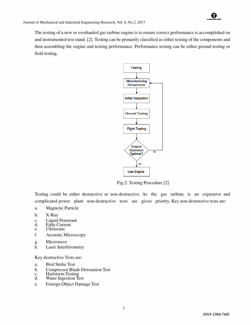
The testing of a new or overhauled gas turbine engine is to ensure correct performance is accomplished on
and instrumented test stand. [2]. Testing can be primarily classified as either testing of the components and
then assembling the engine and testing performance. Performance testing can be either ground testing or
field testing.
Fig.2: Testing Procedure [2]
Testing could be either destructive or non-destructive. As the gas turbine is an expensive and
complicated power plant non-destructive tests are given priority. Key non-destructive tests are:
a. Magnetic Particle
b. X-Ray
c. Liquid Penetrant d. Eddy Current e. Ultrasonic
f. Acoustic Microscopy
g. Microwave
h. Laser Interferometry
Key destructive Tests are:
a. Bird Strike Test
b. Compressor Blade Detonation Test c. Hailstorm Testing d. Water Ingestion Test
e. Foreign Object Damage Test

Journal of Mechanical and Industrial Engineering Research, Vol. 6, No.2, 2017
ISSN 2304-7445
4
Fig.3: Hailstorm Testing
Fig. 4: Compressor Blade Detonation Test
The following parameters are measured during engine testing [2]:
a. Ambient air temperature (Tamb)
b. Ambient air pressure (Pamb) c. Exhaust total pressure (Pt7) d. Low-pressure compressor rpm (N1) e. High-pressure compressor rpm (N2) f. Exhaust-gas temperature (EGT) g. Fuel flow in pounds per hour (Pph) h. Thrust (Fn) i. Low-pressure compressor outlet pressure (Ps3) j. High-pressure compressor outlet pressure (Ps4)
V. Testing methods
Key procedures during engine testing:
a. Disassembly
b. Cleaning
c. Repair
d. Balancing
e. Assembling
There are different tests for different components of the engine.
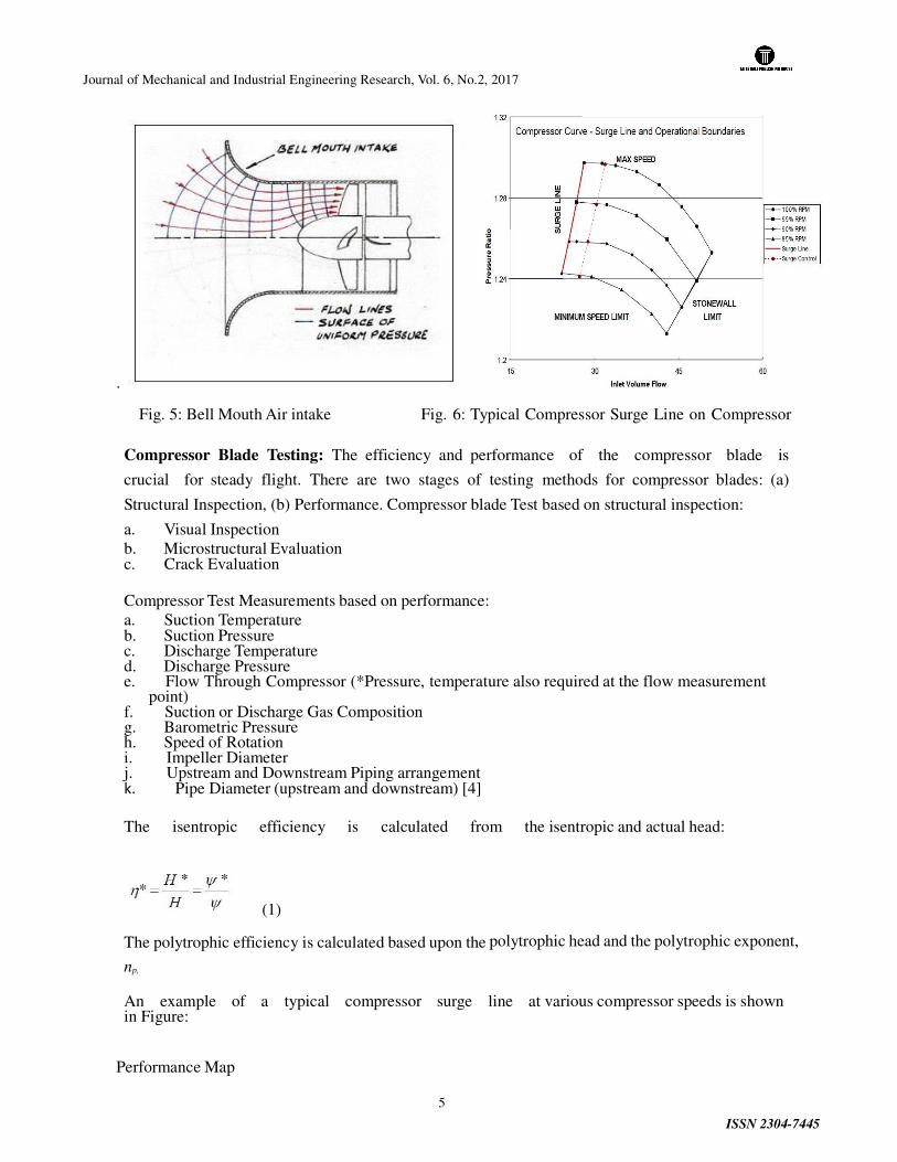
Inlet Testing: By inlet testing flow characteristics is observed. As the purpose of the inlet is to direct air
to the compressor it is essential that the inlet must meet the design requirements. Convergence and
divergence both type of inlet can be used
Journal of Mechanical and Industrial Engineering Research, Vol. 6, No.2, 2017
ISSN 2304-7445
5
.
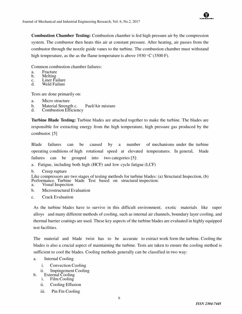
Fig. 5: Bell Mouth Air intake Fig. 6: Typical Compressor Surge Line on Compressor
Compressor Blade Testing: The efficiency and performance of the compressor blade is
crucial for steady flight. There are two stages of testing methods for compressor blades: (a)
Structural Inspection, (b) Performance. Compressor blade Test based on structural inspection:
a. Visual Inspection
b. Microstructural Evaluation c. Crack Evaluation
Compressor Test Measurements based on performance:
a. Suction Temperature b. Suction Pressure c. Discharge Temperature d. Discharge Pressure e. Flow Through Compressor (*Pressure, temperature also required at the flow measurement
point) f. Suction or Discharge Gas Composition g. Barometric Pressure h. Speed of Rotation i. Impeller Diameter j. Upstream and Downstream Piping arrangement k. Pipe Diameter (upstream and downstream) [4]
The isentropic efficiency is calculated from the isentropic and actual head:
(1)
The polytrophic efficiency is calculated based upon the polytrophic head and the polytrophic exponent,
np,
An example of a typical compressor surge line at various compressor speeds is shown in Figure:
Performance Map
Journal of Mechanical and Industrial Engineering Research, Vol. 6, No.2, 2017
ISSN 2304-7445
6
Combustion Chamber Testing: Combustion chamber is fed high pressure air by the compression
system. The combustor then heats this air at constant pressure. After heating, air passes from the
combustor through the nozzle guide vanes to the turbine. The combustion chamber must withstand
high temperature, as the as the flame temperature is above 1930 o C (3500 F).
Common combustion chamber failures:
a. Fracture b. Melting c. Liner Failure d. Weld Failure
Tests are done primarily on:
a. Micro structure
b. Material Strength c. Fuel/Air mixture d. Combustion Efficiency
Turbine Blade Testing: Turbine blades are attached together to make the turbine. The blades are
responsible for extracting energy from the high temperature, high pressure gas produced by the
combustor. [5]
Blade failures can be caused by a number of mechanisms under the turbine
operating conditions of high rotational speed at elevated temperatures. In general, blade
failures can be grouped into two categories [5]:
a. Fatigue, including both high (HCF) and low cycle fatigue (LCF)
b. Creep rupture
Like compressors are two stages of testing methods for turbine blades: (a) Structural Inspection, (b) Performance. Turbine blade Test based on structural inspection: a. Visual Inspection
b. Microstructural Evaluation
c. Crack Evaluation
As the turbine blades have to survive in this difficult environment; exotic materials like super
alloys and many different methods of cooling, such as internal air channels, boundary layer cooling, and
thermal barrier coatings are used. These key aspects of the turbine blades are evaluated in highly equipped
test facilities.
The material and blade twist has to be accurate to extract work form the turbine. Cooling the
blades is also a crucial aspect of maintaining the turbine. Tests are taken to ensure the cooling method is
sufficient to cool the blades. Cooling methods generally can be classified in two way:
a. Internal Cooling
i. Convection Cooling
ii. Impingement Cooling b. External Cooling
i. Film Cooling
ii. Cooling Effusion
iii. Pin Fin Cooling
Journal of Mechanical and Industrial Engineering Research, Vol. 6, No.2, 2017
ISSN 2304-7445
7
iv. Transpiration Cooling
Both of the cooling methods has to be evaluated and re- evaluated before assembling the blades.
Exhaust Testing: The exhaust of a gas turbine engine directs the high velocity gas through the rear of the
engine. The exhaust material must sustain the high velocity and high temperature gasses. The testing
of exhaust is limited to:
a. Alignment
b. Fatigue Resistance c. Material Testing d. Efficiency
VI. Results
The studies conducted in this paper were primarily on various existing methods. Studies show that non-
destructive tests are the most favorable test all over the world. Although in some cases destructive tests are
mandatory.
VII. Conclusion
New and improved testing methods are constantly surfacing. There are still some costly testing methods.
During field testing an engine is completely destroyed to check the intake of blades come off or not. This
methods costs an entire engine. Some important aspects of testing are given below:
a. Testing with cameras and sophisticated fatigue detection algorithm. b. Polymer composites and corresponding structural design and manufacturing techniques can
reduce the build time and testing time. c. Low pressure turbine weight savings through ultra-
high lift airfoil design, ultra high stage loading,
lightweight materials and design can increase engine efficiency and also increase test accuracy.
d. Technologies for light weight and low drag installation of high bypass ratio engines can cool the engine and reduce overhaul time which is essential for a better turn-around time.
NOMENCLATURE
η*: Efficiency
H*: Isentropic Head
H: Actual Head
Ψ*: Isentropic head coefficient Ψ: Actual head coefficient
REFERENCES
[1] FAA, Airframe & Powerplant Mechanics, Powerplant Handbook, pp 38-40, (2008).
[2] Michael J. Kroes, Thomas W. Wild, Aircraft Powerplants, pp 525-535, (2010).
[3] K. Brun, Marybeth G., Nored, Guideline for Field Testing of Gas Turbine and Centrifugal Compressor Performance, pp 15-25, (2006)
[4] Mehdi Tofighi Naeem, Seyed Ali Jazayeri, Nesa Rezamahdi, “Failure Analysis of Gas Turbine Blades”, pp 1-16, (2008)
[5] Boyce, M. P. (2006). Gas Turbine Performance Test. Gas Turbine Engineering Handbook,
Journal of Mechanical and Industrial Engineering Research, Vol. 6, No.2, 2017
ISSN 2304-7445
8
721-760.
[6] Henry Cohen, G.F.C. Rogers, H.I.H.Saravanamuttoo. "Gas Turbine
Theory." Goodreads.
[7] Treager, Irwin E. "Aircraft Gas Turbine Engine Technology." Alibris. N.p., n.d. Web. 01 Feb.
2017.
[8] Horlock, J.H. "Advanced Gas Turbine Cycles." Advanced Gas Turbine Cycles : J.H.
Horlock : 9780080442730. ELSEVIER SCIENCE & TECHNOLOGY, 01 Aug.
2003. Web. 01 Feb.2017.
[9] Oates, Gordon C. "Aerothermodynamics of Gas Turbine and Rocket Propulsion." Alibris. N.p.,
n.d. Web. 01 Feb. 2017.
[10] N. F., & N. P. (2012). Gas Turbine Aero Engine Ground Testing.

Journal of Mechanical and Industrial Engineering Research
http://jmier.elitehall.com


