28
United States Patent [19] Boisvert get a1.
llllllllllllllIllIlllllllllIlllllllllllllllllllllllllllllllllllllllllllllll US005189277A
Patent Number: 5,189,277 Feb. 23, 1993 Date of Patent:
[11]
[45]
MODULAR, STACKABLE PLASMA CUTTING APPARATUS
John A. Boisvert; Fred A. Rogers, both of Grafton; Dennis J. Solley, Merrimack; David A. Tatham; Raymond G. Wilkins, both of Grafton, all of NH.
Thermal Dynamics Corporation, St. Louis, Mo.
Appl. No.: 682,727
Filed: Apr. 8, 1991
Int. Cl.5 ......................... .. B23K 9/00; B23K 9/10 US. Cl. ........................ .. 219/121.54; 219/l2l.48;
219/l30.l Field of Search ................ .. 219/121.5, 121.48, 75,
219/1301, 121.54, 121.57
References Cited
U.S. PATENT DOCUMENTS
4,280,041 7/1981 Kiessling et a1. .......... .. 219/1301 4,985,612 l/l99l lzume et a1. ................... .. 219/1301
FOREIGN PATENT DOCUMENTS 0053774 3/1989 Japan ............................ .. 2l9/12l.54
OTHER PUBLICATIONS
Hypertherm, Inc-Spec. Sheet #82 “Advance Product Information”. ‘
Hypertherm, Inc., Spec. Sheet #42 “Advance Product Information”.
[54]
[75] Inventors:
[73] Assignee:
[211 [22] [51] [52]
[58]
[56]
L-TEC Products-PCM-l50-—Plasmarc Welding & Cutting—-704l-E 6M Nov. 1989. Thermal Dynamics Corp.—PAK SXR-Cat. No. 0-0588 (Aug. 1, 1989). Thermal Dynamics Corp.-DYNAPAK 4XI—Cat. No. O-0737 (Aug. 1989). Thermal Dynamics Corp.-Thermal Arc SOD-Cat. No. 0-0351 Sep. 9, ’87. ‘ Thermal Dynamics-PAK 10XR-Cat. No. 0-0741 (Mar. 15, 1989). Thermal Dynamics-Merlin-PAK l5XC—Cat. No. 0-0752 Jan. 1990. Thermal Dynamics-PAK 7XR-Cat. No. 0-0739 (Feb. 1, 1989). Primary Examiner-Mark H. Paschall Attorney, Agent, or Firm-Paul M. Denk
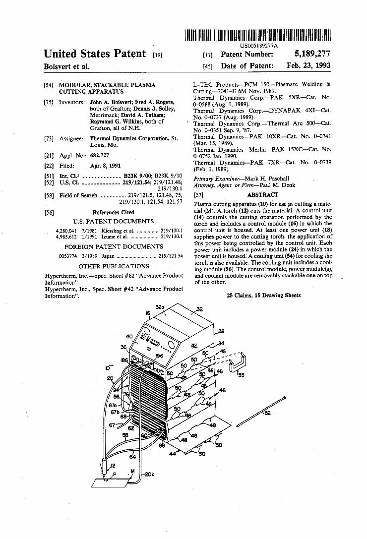
[57] ABSTRACT Plasma cutting apparatus (10) for use in cutting a mate rial (M). A torch (12) cuts the material. A control unit (14) controls the cutting operation performed by the torch and includes a control module (16) in which the control unit is housed. At least one power unit (18) supplies power to the cutting torch, the application of this power being controlled by the control unit. Each power unit includes a power module (24) in which the power unit is housed. A cooling unit (54) for cooling the torch is also available. The cooling unit includes a cool ing module (56). The control module, power module(s), and coolant module are removably stackable one on top of the other.
25 Claims, 15 Drawing Sheets

U.S. Patent Feb. 23, 1993 Sheet 1 of 15

Feb. 23, 1993 Sheet 2 of 15 5,189,277 U.S. Patent
21K. w»

US. Patent Feb. 23, 1993 Sheet 3 of 15 5,189,277


US. Patent Feb. 23, 1993 Sheet 5 of 15 5,189,277
UU

US. Patent Feb. 23, 1993 Sheet 6 of 15 5,189,277
200
ON RUN
E; E, E5 51E
‘ \224'
FIG. 7
36~
300
l ; Elm!“
304
"LEE
ii .:= 306
FIG.7B

US. Patent Feb. 23, 1993 Sheet 7 of 15 5,189,277
r 1 H

US. Patent Feb. 2a, 1993 Sheet 8 of 15 5,189,277
3: . . 4/.
ON: _
lili|l-l|l"l|ll.lillll'l"_

US. Patent Feb. 23, 1993 Sheet 9 of 15 5,189,277 ‘

Feb. 23, 1993 Sheet 10 of 15 5,189,277 US. Patent

5,189,277 5
1 1 w irHJ
,m . Em ‘r m5 H Quin : K. um brig
S
: %¢..> m —
9mm x . mm.
Feb. 23, 1993 US. Patent
L> S w.
1M1» M...
- a]? 3 mwdll $7 ,. w,
. . P W, 0
JIMMM|L . . m?wm {J as . PW @HIAWP m, N a
Lg: ~25 mum ~£
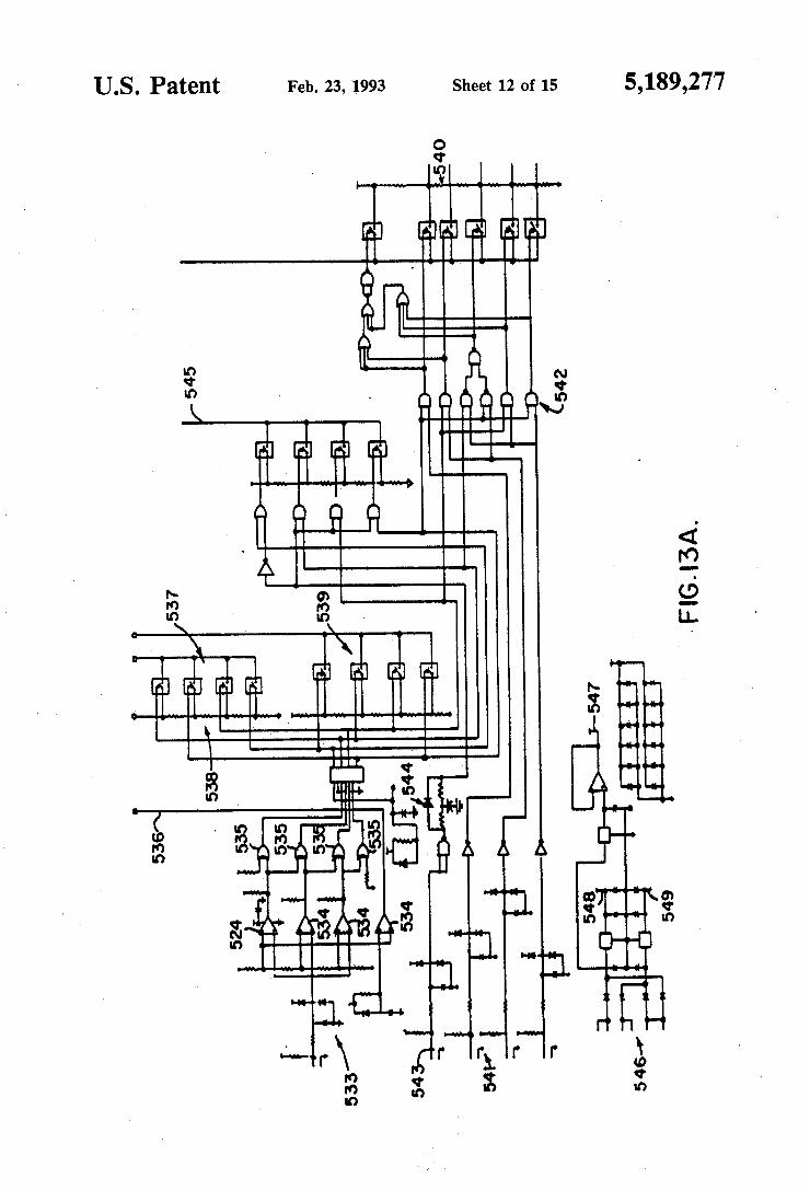
US. Patent Feb. 23, 1993 Sheet 12 of 15 5,189,277


US. Patent Feb. 23, 1993 Sheet 15 of 15 5,189,277

5,189,277 1
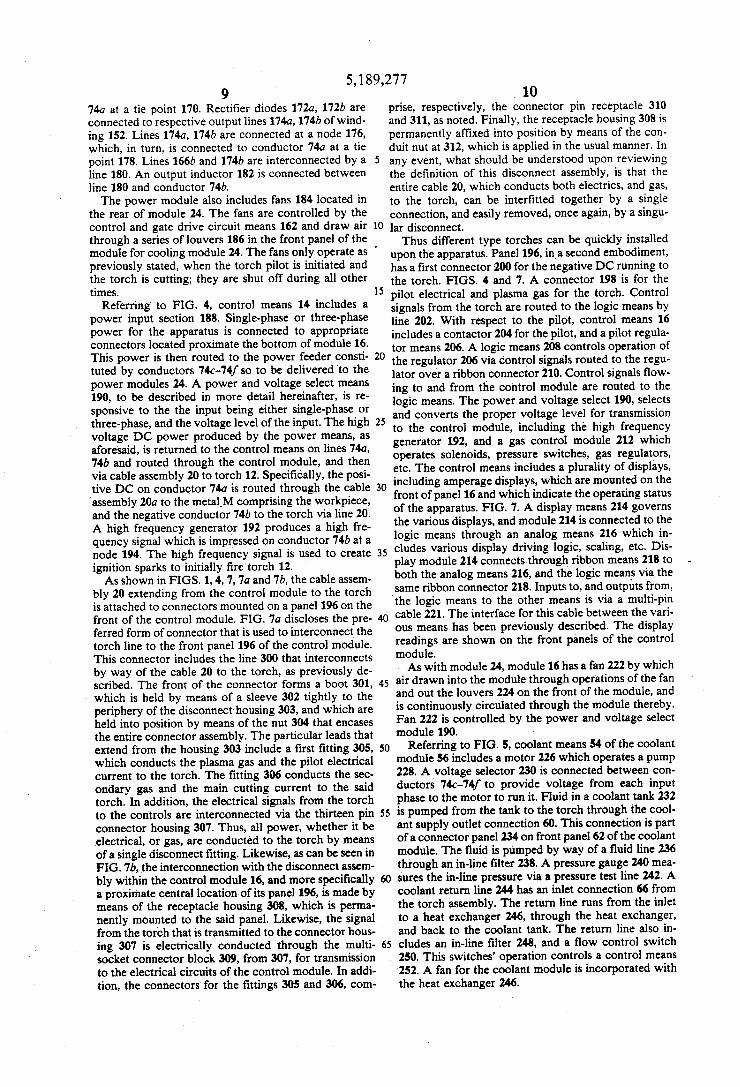
MODULAR, STACKABLE PLASMA CUTTING APPARATUS
BACKGROUND OF THE INVENTION
This invention relates to apparatus for cutting mate rial such as steel or the like using a plasma and, more particularly, to apparatus which is modularized to per mit a wide flexibity in con?guring the power supply, control and cooling equipment used in a plasma cutting operating. The modules comprising the apparatus are removably stackable to simplify changing from one con?guration, for one cutting operation, to a new con ?guration for a different type cutting operation. The invention further includes novel electronics for achiev ing improvements in torch cutting and welding.
Plasma arc welding is well-known in the art and there are many and varied applications for use of plasma arc welding equipment. See, for example, US. Pat. Nos. 4,839,499, 4,590,357, 4,326,842, 4,280,042, and 3,988,566. It is not uncommon in a manufacturing oper ation for different welding equipment set-ups to be re quired. Thus, one set-up may require one type of cutting torch, necessitate use of a power supply capable of delivering a voltage and a current having one set of characteristics (i.e. single or multi-phase power, voltage and amperage levels, etc.), and a particular level of cooling. Another set-up may require a wholly different torch, power, and cooling con?guration. Changing from one set-up to another has heretofore required a substantial amount of time to recon?gure torches, power supplies and cooling equipment. In manufactur ing operations, this “down-time” adds to the overall cost of the product and reduces the volume of units produced. In the alternative, two or more sets of equip ment can be utilized, this equipment being kept in a particular con?guration for whatever operations have to be done. This, of course, increases equipment costs, work and storage space requirements, etc. And, even having a profusion of equipment does not insure that set-up changes will not have to be made. It would be advantageous if it were possible to have apparatus which was capable of performing a myriad of cutting operations but which wassuf?ciently ?exible that the amount of equipment required is minimized, that recon ?guration time for changing set-ups is substantially reduced, and the equipment used will support many varied cutting operations.
SUMMARY OF THE INVENTION
It is an object of the present invention to provide plasma cutting apparatus which is usable in a wide vari ety of manufacturing operations that require differing set-ups for cutting metal. An inherent objective is to provide improvements in welding equipment. A further object of the invention is to-provide plasma
cutting apparatus which is modularized so power, cool ing, and control modules are available which can be arranged in different con?gurations for varied and dif ferent operations and which minimizes the amount of equipment required to support a wide variety of cutting operations. In particular, standard power modules are available which can be so con?gured and arranged that differing power requirements are readily accommo dated. The power modules produce a DC power output and are connectable to either a single-phase or a multi phase AC power source.
5
25
45
55
60
65
2 Another object of the invention is to provide modu
larized plasma cutting apparatus which is stackable to ease con?guration changeovers, reduce the amount of space required for equipment set-up, and consolidate controls, switches, etc. to simplify operations. In partic ular, power, cooling, and control modules are com monly stackable to provide numerous different con?gu rations. Also, power modules having a common set of predetermined operating characteristics are available and are conveniently stackable to provide, for example, a multiple of a standard amperage. This reduces the number of types of power supplies required further reducing equipment costs. A still further object of the invention is to provide
stackable, modularized plasma cutting apparatus which is usable with a variety of torches and power require ments, detects which type torch is being utilized for a particular cutting operation, and automatically provides the appropriate cutting control strategy for the particu lar, torch, power requirement, and cooling con?gura tion. In this regard, the control portion of the apparatus is “smart” in that there is a built-in torch identi?cation, the number of stacked power modules actually being used for a cutting operation is displayed so the user knows exactly how much power is used in a welding operation, and the control strategy, for example, re duces current when the user contacts metal during a “drag” mode of operation. A further object of this invention is to provide means
for electronically detecting the type of torch that is being utilized in the cutting operation, or which has been installed into the system, and which provides through its connecting feature an immediate identi?ca tion which instructs the logic module which torch is on the system, and how the power characteristics for the apparatus must _be converted to accommodate that par ticular torch; the type of torches as known in the art for use in conjunction with such equipment including either a single gas torch, dual gas torch, a liquid cool torch, with the system of this invention incorporating dynam ics that provide for immediate gas selection, maximum output, pilot current setting and drag cutting limit of each torch after its identi?cation has been determined. An additional object of the invention is a stackable,
modularized, apparatus in which the stacked modules are readily interconnected so to not be dislodged one from the other and to ‘be easily transportable. Yet another object of the invention is to provide
stackable modules in which all electrical wiring, signal connections, and power connections are integral to the module. This eliminates generally the need for external electrical wiring between modules. A further object of the invention is to provide a sepa
rate regulated power supply module which provides stable, consistent performance regardless of input line characteristics or the condition of consumable parts of the torch.
Still another object of the invention is to provide modules whose c’nclosures have an outer skin covering which provides strength, durability, and electrical safety.
Yet another object of this invention is to provide for connector means between power and control modules for this invention, which allows for their convenient stackability, so as to build a plurality of power units in combination with the control for operations of the torch, to meet the demands of the particular job being undertaken.

5,189,277 3
Another object of this invention is to provide for the unique and controlled operations of the cooling fans, within the power units, such that the circulating fans function only when the trigger upon the torch is initi ated, as during a cutting cycle, so as to not to perma nently run and continuously draw contaminated air into the power units during functioning of the device. Another advantage of providing for'the staggered
operations of the cooling fans within the power units is that it has a tendency to maintain the electronics and other components within the power units at a consistent temperature, regardless of the number of power mod ules that may be stacked into the device, to assure uni formity of temperature, throughout the stacked power units, during their operation. Thus, when a cutting op eration is taking place, and the power units are operat ing, the cooling fans have a tendency to effect a cooling of the electronic components for each power unit, dur ing that period of time when the electronics are operat ing and functioning, and have a tendency to elevate in temperature, but that when the cutting torch is shut off, such that obviously the electronics of the power unit likewise are turned off, they do not heat up at that time, and maintaining their cooling is not a difficult task. Hence, uniformity of cooling is maintained for the elec tronics of the power units, through the staggered opera tions of the fans, in this manner.
Still a further object of this invention is the provision of electronics for use in ?nely regulating the varied operations of the cutting and welding apparatus of this invention, and which includes the combination of logic means, analog regulating means, and visual digital dis play means, within the control module of this invention, and which regulates the power developed from the power module, during functioning of the device; with these components incorporating unique electronics that furnish, as for example, in the power module, cross coupled windings for attaining mid-point capacitor balancing for consistent and uniform operations of a power module; further includes interleaved power to pology, for attaining consistent power output from each power module; incorporates regulated OC voltage ca pability, to attain quality cut, to enhance part’s life of the apparatus, and to assure consistency of operation; further incorporates the electronics means for attaining, as previously explained, immediate torch identi?cation; and includes magnetic snubbing of the output recti?ers, to maintain precision in apparatus functioning on a con sistent basis.
Yet a primary function of this invention, and one of its principal objectives, in view of the enhancements as previously explained, is to incorporate such improve ments into welding apparatus.
In accordance with the invention, generally stated, plasma cutting apparatus is for use in cutting a material such as steel as part of a manufacturing operation. The apparatus ?rst comprises a cutting torch for cutting the material, the torch being any one of a wide variety of torches, whether the selected torch be one of a single ‘or dual gas torch, or of a liquid or air cooled type. A con trol unit is provided for controlling the cutting opera tion performed using the torches. The control unit is housed in a control module. One or more power supply units for supplying power to the cutting torch are also available. Application of power by the power supply units is controlled by the control unit. Each power unit is separately housed in a power module and the control module and power modules are readily, removably
20
25
30
35
45
50
55
60
65
4 stackable one on top of the other to facilitate set-up changes from one cutting operation to another. A cool ing module is also available which is removably stack able with the control module and power modules. Other objects and features will be in part apparent and in part pointed out hereinafter.
BRIEF DESCRIPTION OF THE DRAWINGS
FIG. 1 is an isometric view of a stacked con?guration of power, cooling, and control modules of the apparatus of the present invention; FIG. 2 is an isometric view of a power module of the
apparatus illustrating the connectors by which one power module is electrically connected with another; FIGS. 3-5 are respective block diagrams of a power
module, control module, and coolant module; FIGS. 6A and 6B are front and side elevational views
of the electrical interconnection, or connectors, be tween adjacent stacked modules; FIG. 7 is an elevational view of the front face of the
control module; FIGS. 7A-7B are exploded views of the connector
that is used to interconnect the torch line to the front panel of the control module; FIG. 8 is a perspective view of an electrical conduc
tor comprising one segment of a power feeder produced by stacking a number of power modules of the appara tus; FIG. 9 is the detailed circuit diagram for the control
and gate drive circuit means; FIG. 10 discloses the power circuitry for the power
module; FIG. 11 discloses the capacitor banks for the power
module, as previously shown in FIG. 10; FIG. 12 discloses the circuitry for the display means
as previously described in FIG- 4; FIGS. 13 and 13A provide the circuit diagram for the
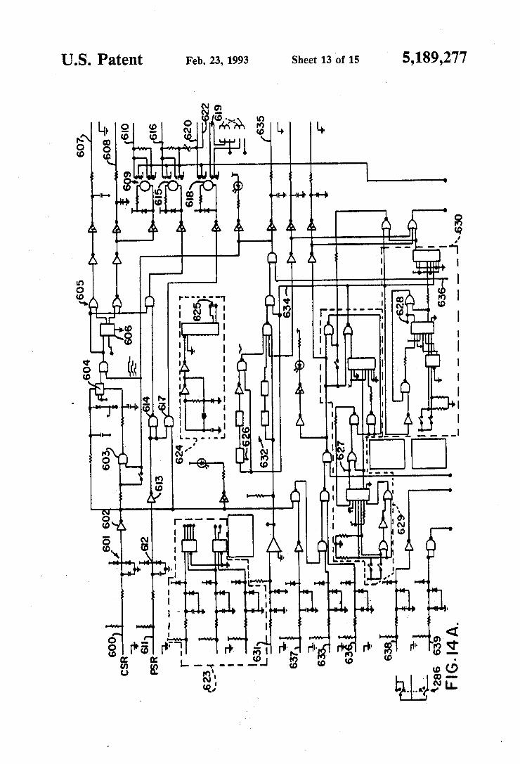
analog means as previously shown in FIG. 4; FIGS. 14A and 14B disclose the circuit diagram for
the logic means, as previously reviewed in FIG. 4; FIG. 15 discloses the high frequency generator as
previously reviewed in FIG. 4; and ' FIG. 16 shows the detailed circuitry for the pilot
regulator as previously explained in FIG. 4. Corresponding reference characters indicate corre
sponding part throughout the drawings. DESCRIPTION OF A PREFERRED
EMBODIMENT
Referring to the drawings, modular, stackable plasma cutting apparatus of the present invention is indicated generally 10. The apparatus is useful in manufacturing operations in which plasma are cutting of metal is per formed. Although, the concepts of this invention can be embodied in welding equipment in general. For the speci?c purpose, apparatus 10 includes a cutting torch 12 which produces a plasma are P for cutting a metal piece M. It will be understood that a variety of torches 12 can be used with the apparatus and the torches have different power requirements for different cutting oper ations, as previously summarized. In general, the tor ches disclosed in any of the following United States patents, and which are assigned to the same assignee as the present application, are incorporated herein by ref erence, are usable with apparatus 10: US. Pat. Nos. 4,748,312; 4,701,590; 4,691,094; 4,581,516; 4,558,201; and 3,813,510. Circuitry and flow con?gurations for such torches, owned by the same assignee, are shown in


![The European Chemical Society (EuChemS)€¦ · &Science and Society The European Chemical Society (EuChemS) David J. Cole-Hamilton[a] Abstract: The European ChemicalSociety(EuChemS)](https://static.documents.pub/doc/80x56/60e49030f254c574d453769e/the-european-chemical-society-euchems-science-and-society-the-european-chemical.jpg)

