Page 1
Issue of Lithium-indium Anode in High Energy andPower All-Solid-State Lithium BatteriesShuting Luo
Tsinghua UniversityZhenyu Wang
Guilin Electrical Equipment Scienti�c Research Institute Co. Ltd.Xuelei Li
Tianjin University of TechnologyXinyu Liu
Guilin Electrical Equipment Scienti�c Research Institute Co. Ltd.Haidong Wang
Tsinghua UniversityWeigang Ma
Tsinghua University https://orcid.org/0000-0003-0178-3994Lianqi Zhang
Tianjin University of TechnologyLingyun zhu
Guilin Electrical Equipment Scienti�c Research Institute Co. Ltd.Xing Zhang ( [email protected] )
Tsinghua University
Article
Keywords: all-solid-state lithium battery, sul�de solid electrolyte, Li-In dendrites, Li dendrites
Posted Date: April 22nd, 2021
DOI: https://doi.org/10.21203/rs.3.rs-402674/v1
License: This work is licensed under a Creative Commons Attribution 4.0 International License. Read Full License
Version of Record: A version of this preprint was published at Nature Communications on November 29th,2021. See the published version at https://doi.org/10.1038/s41467-021-27311-7.
Page 2
1
Issue of Lithium-indium Anode in High Energy and Power 1
All-Solid-State Lithium Batteries 2
3
Abstract: All-solid-state lithium batteries (ASSLBs) using sulfide solid electrolytes 4
(SSEs) offer an attractive option for energy storage applications. Lithium anode is the 5
ultimate goal for ASSLBs, but lithium-indium (Li-In) alloy anode is more widely 6
utilized in lab testing owing to the quite stable interface and elimination for the risk of 7
short circuit. However, vigorous growth of Li-In dendrites in SSE is discovered in the 8
present work when a full cell (LiNbO3 coated LiNi0.6Co0.2Mn0.2O2//Li6PS5Cl//Li-In) is 9
cycled in high loading and high rate. Our study demonstrates that Li-In anode is 10
unstable towards SSEs at high current, which induces Li-In dendrite growth enclosing 11
electrolyte particles and eventually results in cell death after a long cycling. The 12
morphology and growth mechanism of Li-In dendrites are revealed by scanning 13
transmission electron microscopy-electron energy loss spectroscopy (STEM-EELS) 14
analysis and density function theory (DFT) calculations. Moreover, the differences 15
between Li and Li-In dendrites are systematically compared. 16
Keywords: all-solid-state lithium battery; sulfide solid electrolyte; Li-In dendrites; Li 17
dendrites 18
19
1. Introduction 20
The thermal instability of conventional lithium-ion batteries (LIBs) which originated 21
from the intrinsic characteristics of liquid electrolytes causes safety issues and has 22
Page 3
2
become a serious impediment to the automotive application. All-solid-state lithium 1
batteries (ASSLBs) using nonflammable solid electrolytes may not only overcome the 2
safety concerns in LIBs but also achieve high energy density 1, 2, 3, 4, 5. Lithium metal is 3
recognized as the most attractive choice for anode material to achieve high energy 4
density due to the low electrochemical potential (-3.04 V vs. the standard hydrogen 5
electrode) and high theoretical specific capacity (3860 mAh g-1). However, pure Li 6
metal is unsatisfying in sulfide-based ASSLBs because of the severe interfacial side 7
reactions 6, 7, 8 and the growth of Li dendrites 9, 10, 11. Lithium alloys provide an attractive 8
alternative to construct a stable SSEs-electrode interface that enables the long-term 9
cycling for ASSLBs 12. Lithium alloys can be easily prepared by solid-state diffusion 10
method at ambient temperature. A number of alloys including Li-Al 13, Li-In 14, 15, Li-11
Si 16, Li-Au 17, 18, 19, Li-Sn 20 have been reported as interlayers or solid solution for 12
sulfide-based ASSLBs. Generally, alloy layer or bulk has higher lithium diffusivity than 13
pure lithium, which is favorable for lithium transport towards interface and thus a 14
uniform lithium plating can be achieved 21, 22. In addition, the insertion of lithium into 15
other metals can reduce the lithium chemical potential and suppress the electrochemical 16
decomposition of SSEs 23, 24. 17
Among various lithium alloys, Li-In alloy is particularly popular due to the great 18
mechanical ductility and constant redox potential (about 0.6 V vs. Li+/Li) over a wide 19
stoichiometry range 15. Li-In alloy is usually considered as a thermodynamically and 20
kinetically stable material towards SSEs and is widely used in the laboratory for testing 21
the performance of electrolytes or cathodes. Li-In alloys exhibit excellent long-cycling 22
Page 4
3
stability towards SSEs in ASSLBs. However, most batteries were cycled at low current 1
(< 0.5 mA cm-2, <0.5 C) 25, 26, 27, it is unclear whether or not Li-In alloy anode is still 2
stable towards SSEs at high current, which is critical for the high power applications of 3
ASSLBs. There are rare investigations to clarify the issue. 4
In the present work, we cycled a full cell at high loading (4 mAh cm-2) and high rate 5
(1C) to investigate the interface stability between sulfide electrolyte and Li-In anode. 6
Unexpectedly, the cell has a short circuit after 897 cycles, which is similar as using Li 7
metal anode. Combined with scanning electron microscope (SEM) and scanning 8
transmission electron microscope (STEM) observations, we discovered the growth of 9
Li-In dendrites in LPSCl solid electrolyte, which leads to a rapid capacity fading and 10
subsequent battery failure. The underlying mechanism for Li-In dendrite growth is 11
revealed by electron energy loss spectroscopy (EELS) analysis and ab initio molecular 12
dynamics (AIMD) simulations. The differences between Li and Li-In dendrites in 13
morphology and growth mechanism are also compared. 14
15
2. Results and discussion 16
2.1. Cell failure for ASSLBs using Li-In alloy 17
The purity of synthesized LPSCl was determined by XRD patterns (Figure S1 in 18
supporting information). All the diffraction peaks are well indexed to the pure phase 19
Li7PS6. The electrolyte LPSCl has a high ion conductivity of 2.95×10⁻³ S cm-1 at room 20
temperature (RT) as measured by electrochemical impedance spectroscopy (Figure S2). 21
The NCM622 particles were uniformly coated by LNO with around 10 nm thickness as 22
Page 5
4
shown in Figure S3. The SEM image of the cross section of prepared Li-In alloy is 1
shown in Figure S4 with alloy phase circled by blue dotted lines. Due to the good creep 2
property of lithium, Li metal diffuses into the In metal and the formed alloy phase is 3
uniformly distributed in indium matrix. 4
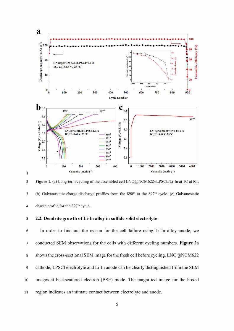
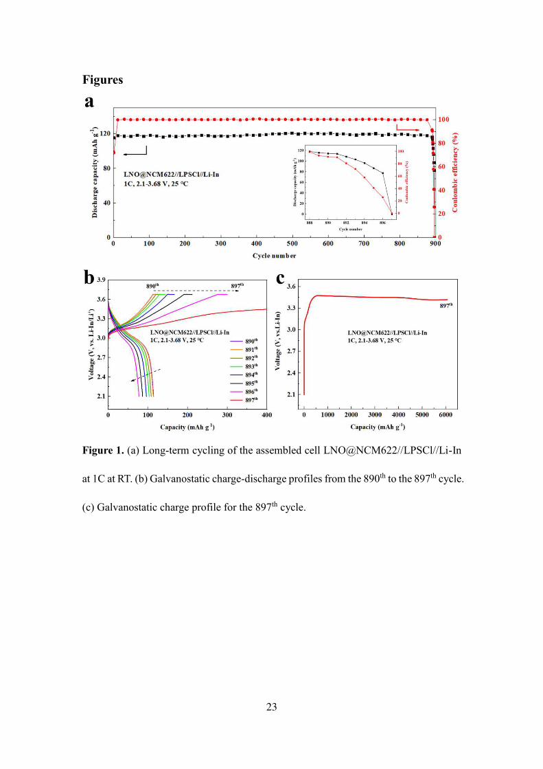
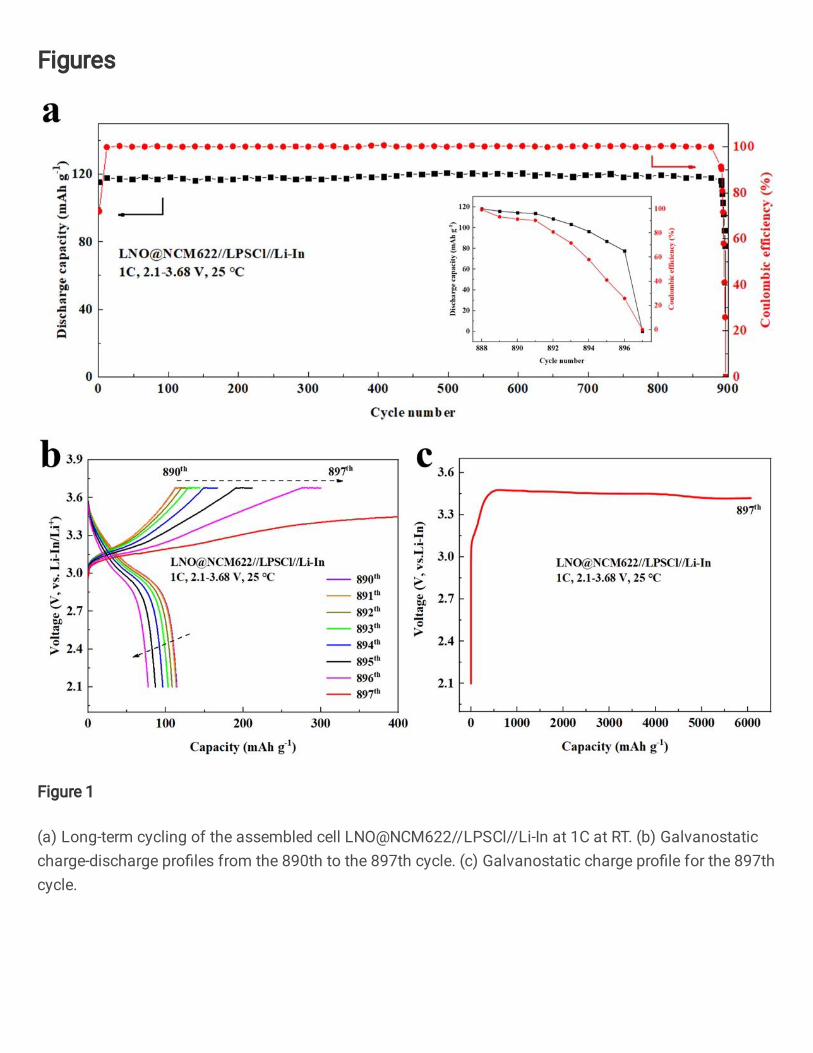
Figure 1a shows the long-term cycling of the assembled cell 5
LNO@NCM622//LPSCl//Li-In at 1C at RT with a high loading of 4 mAh cm-2. The 6
cell maintains a stable cycling capacity and near 100% columbic efficiency during the 7
charge-discharge cycle up to 890 cycles (Figure 1a). However, the capacity started to 8
decline after 891 cycles, and finally the discharge capacity decreased to ~ 0 at the 897th 9
cycle. Figure 1b displays the related charge-discharge voltage profile from the 891th to 10
the 897th cycle of the cell, in which the charge specific capacity increased gradually 11
while the corresponding discharge specific capacity decreased. At the 897th cycle, the 12
cell was continuously charged with everlasting capacity increase accompanying a lower 13
voltage increasing rate as illustrated in Figure 1c, which indicates the appearance of 14
internal short circuit and cell death. These results are similar to those of using lithium 15
anode, which indicates that Li-In alloy anode is not forever stable for sulfide electrolyte, 16
especially after a longer charge-discharge cycle with a high current density. 17
Page 6
5
1
Figure 1. (a) Long-term cycling of the assembled cell LNO@NCM622//LPSCl//Li-In at 1C at RT. 2
(b) Galvanostatic charge-discharge profiles from the 890th to the 897th cycle. (c) Galvanostatic 3
charge profile for the 897th cycle. 4
2.2. Dendrite growth of Li-In alloy in sulfide solid electrolyte 5
In order to find out the reason for the cell failure using Li-In alloy anode, we 6
conducted SEM observations for the cells with different cycling numbers. Figure 2a 7
shows the cross-sectional SEM image for the fresh cell before cycling. LNO@NCM622 8
cathode, LPSCl electrolyte and Li-In anode can be clearly distinguished from the SEM 9
images at backscattered electron (BSE) mode. The magnified image for the boxed 10
region indicates an intimate contact between electrolyte and anode. 11
Page 7
6
1
Figure 2. Cross-sectional SEM images for the cell LNO@NCM622//LPSCl//Li-In (a) before 2
cycling, (b) after 100 cycles and (c) after 897 cycles. 3
For the cell cycled 100 times shown in Figure 2b, different from the fresh state, Li-4
In alloy grows into the electrolyte for around 20 μm and exhibits flame shape at the 5
anode-electrolyte interface. We called the Li-In anode that grows into the electrolyte as 6
Li-In dendrites. For the dead cell after 897 cycles, the Li-In alloy exhibits a striking 7
growth towards electrolyte interior with around 500 μm, nearly having a contact with 8
cathode. Li-In alloy almost entirely enters into the electrolyte without significant anode 9
layer observed. Due to the growth inhomogeneity of Li-In dendrites at different 10
positions and limited area of observation, Li-In alloy has definitely penetrated through 11
Page 8
7
the electrolyte at some locations and results in short circuit and cell death. In the 1
meantime, there is no significant structure or composition change for cathode and 2
cathode-electrolyte interface as demonstrated in Figure S5.Therefore, the cell failure of 3
ASSLB using Li-In anode at high current is induced by the growth of Li-In dendrites. 4
To deeply analyze the morphology of Li-In dendrites in LPSCl electrolyte, SEM and 5
EDX observations were conducted at various positions for the cell cycled 897 times. 6
The SEM image at the middle of Li-In dendrites (red boxed area in Figure 3a) are 7
displayed in Figure 3b. It is clearly observed that the Li-In dendrites grow densely and 8
laterally in stripes, which is further demonstrated by the EDX mapping of indium 9
element (Figure 3f). Elements of P, S, Cl (Figure 3c-3e) are uniformly distributed in the 10
LPSCl electrolyte. Although the Li-In alloy grows wildly in the electrolyte, there are 11
no obvious cracks and voids observed. The high compactness of the electrolyte 12
indicates that the Li-In dendrites have lower growth stress than Li dendrites without 13
severe structural damage for electrolyte itself. 14
Page 9
8
1
Figure 3. (a) Cross-sectional SEM images of the cell LNO@NCM622//LPSCl//Li-In after 897 2
cycles. (b) SEM image and EDX mapping of (c) P, (d) S, (e) Cl and (f) In at the middle of Li-In 3
dendrites. SEM images at (g) the top of Li-In dendrites, (h) the In-rich layer and (i) the interface 4
between electrolyte and In-rich layer. SEM images of Li-In dendrites from an oblique view after the 5
cell was soaked and washed with the deionized water at (j) low magnification and (k) high 6
magnification. 7
Figure 3g shows the morphology at the top of Li-In dendrites (blue boxed area in 8
Page 10
9
Figure 3a). Different from the streak pattern at the middle of Li-In dendrites, it displays 1
a flame shape, which is similar as the morphology shown in Figure 2d after 100 cycles. 2
From the perspective of time and space, it can be inferred that flame shape is the initial 3
morphology of Li-In dendrites. At the very bottom of the Li-In dendrites, there remains 4
an In-rich layer with around 10 μm thickness (white region). We performed SEM 5
characterizations for the In-rich layer (Figure 3h, green boxed area) and the In-rich 6
layer-electrolyte interface (Figure 3i, black boxed area), respectively. As seen from 7
Figure 3c, the electrolyte is broken into smaller particles with less than 4 μm diameter. 8
The particle diameter becomes smaller with getting closer to the bottom. Li-In dendrites 9
exhibit a form of network enclosing the broken electrolyte particles. Two kinds of 10
morphologies of Li-In dendrites appear at the In-rich layer-electrolyte interface, as 11
shown in Figure 3i. The upper part exhibits streak pattern, which is consistent with the 12
morphology at the middle of Li-In dendrites. The lower part shows network formation, 13
which is in accord with In-rich layer. Therefore, it is in a transition state. 14
In order to more clearly observe the morphology of Li-In dendrites without the 15
influence of electrolyte, a part of the dismantled specimen of the 16
LNO@NCM622//LPSCl//Li-In cell was soaked and washed in deionized water for 2 17
hours and then dried for 24 hours, by which the LPSCl electrolyte and cathode materials 18
can be removed via chemical reaction. Figure 3j and 3k shows the SEM images of Li-19
In alloy anode from the oblique view at low and high magnifications, respectively. 20
Obviously, Li-In dendrites grow densely and uniformly over a wide region, like a 21
honeycomb that wraps the electrolyte particles in them. 22
Page 11
10
Based on the above results, it can be concluded that Li-In alloy is unstable towards 1
SSEs when cycled at a high current even though it exhibits excellent stability at low 2
current. The formed Li-In dendrites can penetrate the solid electrolyte after a long cycle 3
and eventually results in short circuit and cell failure. From the top to the bottom of Li-4
In dendrites, the morphology changes from flame shape, to the stripe and then to the 5
network, which has a similar evolution in time with the increase of cycling number. It 6
should be noted that striped dendrites occupy the majority and this morphology is 7
favorable for reducing the growth rate of Li-In dendrites. More importantly, these three 8
types of Li-In dendrites have one thing in common, that is they have no significant 9
destructive effect on electrolyte structure. No apparent cracks are observed even the 10
electrolyte particles were divided into smaller particles in the In-rich layer. The 11
electrolyte layer maintains a high density overall. Li-In dendrites mainly grow along 12
the grain boundaries and have a great wettability with electrolyte particles. 13
2.3. Growth mechanism for Li-In dendrites 14
Indium metal is commonly considered as a stable material towards sulfide electrolyte, 15
so it is widely used for ASSLBs testing. Besides, metal In do not participate in 16
electrochemical cycling in lithium ion batteries. How does it violently grow in SSEs? 17
In order to find out the reason, STEM characterization were performed to reveal the 18
growth mechanism for Li-In dendrites. Figure 4a and 4b show the STEM images of Li-19
In dendrites at low and high magnifications, respectively. It is clearly illustrated that 20
there exists a 15 nm-thick interphase layer at the In-LPSCl interface. As observed from 21
the STEM image and EDX mapping shown in Figure 4c and 4d, there exists an obvious 22
Page 12
11
change of element contents in the interphase layer. Elements of P, S, Cl in the electrolyte 1
and element of In exhibit an opposite variation trend at the interphase layer. Due to the 2
high content of element S in LPSCl, the interphase layer is mainly composed of indium 3
and sulfur elements. Therefore, some indium-sulfur compounds may be generated at 4
the interphase layer. In addition, the interphase layer has an intimate contact with 5
electrolyte as observed from Figure 4b, which enables the high compactness of 6
electrolyte during the growth of Li-In dendrites. 7
8
Figure 4. STEM images for (a) Li-In dendrites, (b) magnified Li-In dendrites with interphase layer 9
and (c) magnified Li-In dendrites used for performing EDX. (d) EDX mapping of P, S, Cl and In in 10
the direction of the red arrow. 11
STEM-EELS analysis was conducted to further determine the component of 12
interphase layer. Figure 5a shows the STEM images for Li-In dendrites and 13
corresponding EELS mapping of In and S for the magnified boxed area. The element 14
Page 13
12
distributions of the interphase layer are more clearly observed from the EELS mapping. 1
The variation trends of In and S in the direction perpendicular to the anode-electrolyte 2
interface agrees well with EDX mapping shown in Figure 4d. The electron energy loss 3
spectra for Li-In dendrite, LPSCl electrolyte and their interphase layer are shown in 4
Figure 5b. A new phase that different from metal In and LPSCl electrolyte is generated 5
at the interphase layer, which provides a direct evidence for interfacial reaction. 6
7
Figure 5. (a) STEM images of Li-In dendrites and corresponding EELS mapping of In and S for 8
Page 14
13
the magnified boxed area. (b) Electron energy loss spectra for Li-In dendrite, LPSCl electrolyte and 1
their interphase layer. (c) LPSCl-In interface models before MD (0 ps) and after MD (20 ps). (d) 2
Evolutions of RDFs of In-S, In-Cl and P-S for LPSCl-In interface during simulation and RDFs of 3
In-S, In-Cl and P-S for reference materials (InS, InCl) with the initial structure (before MD) 4
provided as a reference. 5
Then, first-principles calculations were further performed to investigate the interface 6
reaction between metal In and LPSCl electrolyte. The dynamic changes of LPSCl-In 7
interface were simulated using AIMD at 300 K and the structural variation was tracked 8
by radial distribution function (RDF). Figure 5c shows all the formed bonds after AIMD 9
(20 ps) as well as the interface model before AIMD (0 ps). It can be clearly found that 10
quite a number of In-S bonds and a small amount of In-Cl bonds were formed after MD 11
at the LPSCl-In interface. The upper part in Figure 5d shows the evolutions of In-S, In-12
Cl and P-S pairs during the first 20 ps. The lower part plots the In-S RDF of InS, In-Cl 13
RDF of InCl, and RDF of the initial structure (before MD) provided as a reference. The 14
structures of known crystalline compounds (InS and LnCl) were obtained from 15
Materials Project (MP) database. At the very beginning of the simulation, no In-S and 16
In-Cl bonds are found matching those in InS and InCl. The initial formation of In-S and 17
In-Cl bonds is at ~1 ps. During the simulation, the intensity of In-S bonds (~2.8 Å) 18
gradually increases and then keep stable, indicating the formation of stable reaction 19
product InS. However, the intensity of In-Cl bonds (2.9 Å) has been fluctuating during 20
20 ps, which means InCl is an unstable intermediate product and easily decomposes. 21
Moreover, due to the low content of Cl in the LPSCl electrolyte, the amount of InCl is 22
Page 15
14
much less than that of InS, which can be reflected from the number of In-S bonds and 1
In-Cl bonds in Figure 5c. Therefore, InS should be the main reaction product. 2
EELS results and AIMD simulations demonstrates that chemical side reaction occurs 3
at the In-LPSCl interface and the generation of InS is thermodynamically favorable. 4
However, whether the growth of Li-In dendrites can continue depends not only on 5
thermodynamic favorability, but also on kinetic feasibility. The growth rate of Li-In 6
dendrites is closely related to the charging-discharging current. When the cell is cycled 7
at a high current, a large amounts of lithium ions enters into the indium matrix during 8
charging, which will induce the volume expansion of dendrite tip. Obviously, grain 9
boundary is the preferential expansion channel due to the least resistance. In addition, 10
the new produced InS at the interface improves the wettability behavior between Li-In 11
and LPSCl particles, which results in an intimate contacting interface and honeycomb 12
dendrite structure. Therefore, the formed Li-In dendrites fills the grain boundaries like 13
liquid and tightly enclose the electrolyte particles, which enables the structural stability 14
of the electrolyte. 15
2.4. Comparison between Li-In dendrites and Li dendrites 16
Lithium dendrites have been widely investigated in recent decades, however, the 17
formation of Li-In dendrites is firstly reported in this work. In order to find out the 18
difference between Li and Li-In dendrites, we performed corresponding 19
electrochemical measurements and SEM observations for LNO@NCM622//LPSCl//Li 20
cell. The cycling performance and the galvanostatic charge-discharge profiles are 21
shown in Figure S6. Compared with the cell using Li-In anode, it has a much shorter 22
Page 16
15
cycling life (17 cycles) and a much lower charge/discharge current (0.3 mA cm-2). A 1
similar short circuit occurs in the last few cycles caused by the growth of Li dendrites. 2
The charge capacity gradually increases, while discharge capacity and coulombic 3
efficiency simultaneously decreases and finally to zero. 4
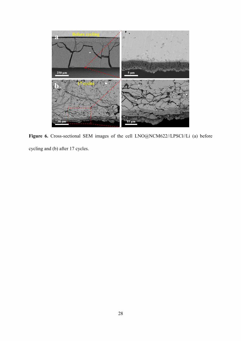
Figure 6a presents the cross-sectional SEM images for the fresh 5
LNO@NCM622//LPSCl//Li cell without cycling. The cracks are caused by the cell 6
disassembly, which is common in non-binder cell. The magnified image of the boxed 7
area includes a part of the LPSCl electrolyte adjacent to Li anode. The interphase layer 8
with “grey” at the interface is evidently different from Li anode and LPSCl electrolyte 9
observed from the high-contrast BSE image, indicating a severe interfacial side reaction 10
between Li and LPSCl. After 17 cycles as shown in Figure 6b, the growth of Li 11
dendrites is much sharper than that of Li-In dendrites and exhibits a different growth 12
morphology. Li dendrites not only grow along the grain boundaries, but also destroy 13
the electrolyte structure and induces much cracks, which results in a rapid short circuit 14
within several cycles. 15
Page 17
16
1
Figure 6. Cross-sectional SEM images of the cell LNO@NCM622//LPSCl//Li (a) before cycling 2
and (b) after 17 cycles. 3
Combined with the Li-In dendrites shown above, we can find that there exist 4
significant differences between Li-In and Li dendrites. Firstly, they have different 5
growth morphologies. Lithium dendrites grow vertically, perpendicular to the anode-6
electrolyte interface. Lithium-indium dendrites grow laterally in stripes, much denser 7
and much more uniform than Li dendrites. This is because the growth of Li dendrites is 8
induced by the non-uniform Li deposition that prefers to form whiskers and Li-In 9
dendrites is caused by the volume expansion and slight interface reaction. Therefore, 10
Li-In dendrites have a slower growth rate during cycling. This inspires us that 11
converting Li deposition morphology might be a novel strategy to realize the 12
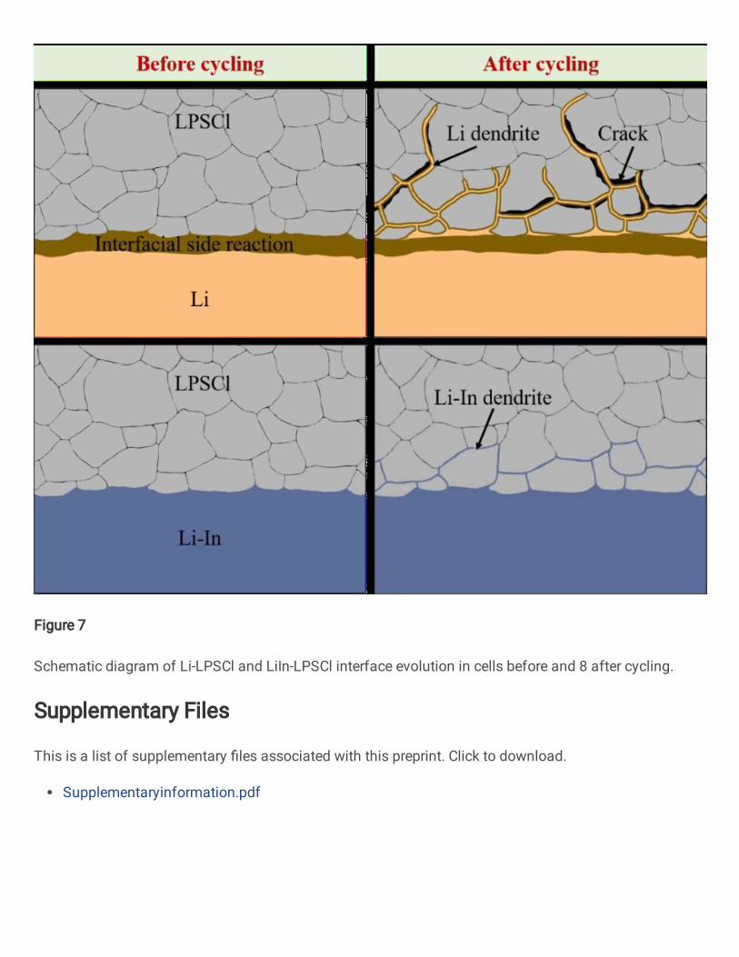
application of Li metal anode. Secondly, they have different wettability with electrolyte. 13
The growth of Li dendrites causes many cracks and voids in the electrolyte due to the 14
stress concentration and high reactivity, which leads to a loose and porous electrolyte 15
Page 18
17
structure. But for metal Li-In anode, the formation of thin interphase layer (15 nm) due 1
to the slight interfacial reaction enables the great wettability between LiIn-LPSCl 2
interface and the dense structure of electrolyte could be achieved. The schematic 3
diagram of Li-LPSCl and LiIn-LPSCl interface evolution in cells before and after 4
cycling is shown in Figure 7. The suppression of Li-In dendrites and the morphological 5
modification of Li dendrites warrant further investigation. 6
7
Figure 7. Schematic diagram of Li-LPSCl and LiIn-LPSCl interface evolution in cells before and 8
after cycling. 9
3. Conclusion 10
In summary, we discovered the growth of Li-In dendrites in sulfide electrolyte and 11
clarified the dendrite morphology and growth mechanism using SEM-EDX analysis, 12
STEM-EELS analysis and AIMD simulations. Our finding suggests that metal In is 13
thermodynamically unstable towards sulfide electrolytes and possibly produces InS at 14
the LiIn-LPSCl interface. When the cell cycled at a high current, the accompanied 15
Page 19
18
volume change and slight interfacial reaction will cause the growth of Li-In dendrites 1
enclosing electrolyte particles, eventually leading to short circuit and cell death after a 2
long cycling. Compared with vertically growing Li dendrites (Figure 6b), laterally 3
striped Li-In dendrites (Figure 3b) are favorable for reducing the growth rate of 4
dendrites and alleviating structural damage on sulfide electrolyte, which provides a new 5
strategy for modifying Li metal anode to improve cycling life. Our investigation reveals 6
the failure mechanism of ASSLBs using Li-In anode and gives a valuable insight on the 7
Li-In dendrites, which will provide rational guidance for testing the performance of 8
sulfide-based ASSLBs. 9
4. Methods 10
Material synthesis: Sulfide solid electrolyte LPSCl was produced by GLESI, 11
CHINA. Li2S (>99.9% purity, Alfa Aesar), P2S5 (>99% purity, Alfa Aesar) and LiCl 12
(>99.9% purity, Alfa Aesar) were first mixed in an appropriate molar ratio. The mixture 13
was then placed in a ZrO2 pot containing a ZrO2 ball to be mechanically milled using 14
the planetary ball milling apparatus at 500 r.p.m. for 30 hours. Following the ball 15
milling procedure, the mixture was heated at 550 ℃ for 6 hours under argon (Ar) 16
atmosphere with H2O and O2 < 0.1 ppm. 17
LiNbO3 coated LiNi0.6Co0.2Mn0.2O2 (LNO@NCM622) was provided by GLESI, 18
CHINA. By means of the fluidized bed technology, the LNO coating layer was formed 19
with an ethanol solution of Li and Nb. Metal Li and niobium ethoxide (>99.9% purity, 20
Alfa Aesar; molar ratio, Li:Nb = 1:1) were dissolved in anhydrous ethanol (Kanto 21
Chemical) under Ar atmosphere. The solution was sprayed onto NCM622 particles at a 22
Page 20
19
spraying rate of 2 g min-1 by a rolling fluidized coating machine (Powrex, MP-01). The 1
LNO@NCM622 was finally heated at 400 ℃ for 60 min under O2. The coating layer 2
thickness can be controlled by spraying duration. Lithium-indium (Li-In) alloy was 3
prepared by solid-state diffusion method. Li metal and In metal with a weight ratio of 4
2:98 was combined under a 760 Mpa pressure. 5
Fabrication of all-solid-state lithium battery: As-synthesized LNO@NCM622 6
powder was mixed with LPSCl electrolyte powder in a mass ratio of 70:30 using an 7
agate mortar, and the obtained composite was used as cathode for the full cell. Li-In 8
alloy foil was used as anode. Cells were assembled as follow: 80 mg LPSCl electrolyte 9
powder was pressed under 150 MPa into an electrolyte layer with a diameter of 10 mm. 10
Then, 40 mg composite cathode powder was uniformly spread on one side of the 11
electrolyte layer and then a stainless steel (SS) foil was put on composite cathode layer. 12
Next, Li-In alloy (~ 25 g) was placed on the other side of the electrolyte layer with a 13
SS foil as collector. Finally, all the components were compressed together under 760 14
MPa to form full cell. For the reference cell LNO@NCM622//LPSCl//Li, the Li-In 15
anode was replaced by Li metal (~ 5 μm thickness) and the pressure was changed from 16
760 MPa to 100 Mpa with other conditions remaining consistent. 17
Materials Characterizations: X-ray diffraction pattern (XRD, Rigaku D/MAX-500, 18
Japan) of the LPSCl electrolyte was recorded by using Cu Kα radiation in the 2θ range 19
of 10-60° with a step size of 0.02°. Scanning electron microscope (SEM) equipped with 20
energy-dispersive X-ray spectroscopy (EDX) (JEOL, JSM-7900F, Japan) was used to 21
analyze the cross-sectional morphology of the cell. The sample cross section was 22
Page 21
20
polished using a cross section polisher (JEOL, IB-19520CCP, Japan) before SEM-EDX 1
analysis. The microstructure of the tested sample was characterized by cryo-scanning 2
transmission electron microscope (cryo-STEM, HD2700, Hitachi) at -100 ℃. Element 3
distribution was observed via EDX (XMAXN 100TLE, Oxford) and component 4
analysis was performed using electron energy loss spectroscopy (Enfinlum, Gatan). 5
STEM specimens were obtained by thinning the electrolyte layer with dual-beam 6
focused ion beam equipment (FIB, NB5000, Hitachi) operated at 2-30 kV. A special 7
compatible holder was used to enable the sample directly transferred from the FIB 8
equipment to cryo-STEM without exposure in the air. 9
Electrochemical measurements: The conductivity of LPSCl was measured on a 10
SS/LPSCl/SS cell using electrochemical workstation (EIS, Bio-Logic VSP-300) over a 11
frequency range of 6 MHz-1 Hz at room temperature. For the long-term cycling, the 12
cell LNO@NCM622//LPSCl//Li-In was charged to 3.68V (vs. Li-In/Li+, 4.3 V vs. 13
Li/Li+) at a constant current mode (1C) and then charged at constant voltage mode (3.68 14
V) for 15 minutes. After that, the cell was discharged at 1C to 2.1 V (vs. Li-In/Li+, 2.72 15
V vs. Li/Li+). The average charge and discharge voltage are 3.4 V and 3.1 V, 16
respectively. 17
AIMD calculations: AIMD simulations are performed in the Vienna Ab initio 18
Simulation Package (VASP) with the projector augmented wave (PAW) method. The 19
exchange-correlation potential is described by the generalized gradient approximation 20
(GGA) function, which is parameterized with Perdew-Burke-Ernzerhof (PBE). 500 eV 21
of cutoff energy for plane-wave is set, and 1×1×1 K-point mesh in the first Brillouin 22
Page 22
21
zone is used as the large atom numbers (>250) of the interfacial models. NVT ensemble 1
based on a Nosé thermostat and time step of 2 fs are adopted in the AIMD simulations. 2
Data availability 3
The data that support the findings of this study are available from the corresponding 4
author upon reasonable request. 5
References 6
1. Goodenough J. B., Park K. S. The Li-ion rechargeable battery: A perspective. J. Am. Chem. Soc. 135, 7
1167-1176 (2013). 8
2. Takada K. Progress and prospective of solid-state lithium batteries. Acta. Mater. 61, 759-770 (2013). 9
3. Lau J., DeBlock R. H., Butts D. M., Ashby D. S., Choi C. S., Dunn B. S. Sulfide solid electrolytes for 10
lithium battery applications. Adv. Energy. Mater. 8, (2018). 11
4. Tan D. H. S., Banerjee A., Chen Z., Meng Y. S. From nanoscale interface characterization to 12
sustainable energy storage using all-solid-state batteries. Nat. Nanotechnol. 15, 170-180 (2020). 13
5. Lee Y. G., et al. High-energy long-cycling all-solid-state lithium metal batteries enabled by silver-14
carbon composite anodes. Nat. Energy 5, 348-348 (2020). 15
6. Wenzel S., Leichtweiss T., Kruger D., Sann J., Janek J. Interphase formation on lithium solid 16
electrolytes-An in situ approach to study interfacial reactions by photoelectron spectroscopy. Solid State 17
Ionics 278, 98-105 (2015). 18
7. Wenzel S., Weber D. A., Leichtweiss T., Busche M. R., Sann J., Janek J. Interphase formation and 19
degradation of charge transfer kinetics between a lithium metal anode and highly crystalline Li7P3S11 20
solid electrolyte. Solid State Ionics 286, 24-33 (2016). 21
8. Wenzel S., Sedlmaier S. J., Dietrich C., Zeier W. G., Janek J. Interfacial reactivity and interphase 22
growth of argyrodite solid electrolytes at lithium metal electrodes. Solid State Ionics 318, 102-112 (2018). 23
9. Porz L., et al. Mechanism of lithium metal penetration through inorganic solid electrolytes. Adv. 24
Energy Mater. 7, (2017). 25
10. Kasemchainan J., et al. Critical stripping current leads to dendrite formation on plating in lithium 26
anode solid electrolyte cells. Nat. Mater. 18, 1105-1112 (2019). 27
11. Schlenker R., et al. Understanding the lifetime of battery cells based on solid-state Li6PS5Cl 28
electrolyte paired with lithium metal electrode. ACS Appl. Mater. Inter. 12, 20012-20025 (2020). 29
12. Obrovac M. N., Chevrier V. L. Alloy negative electrodes for Li-ion batteries. Chem. Rev. 114, 11444-30
11502 (2014). 31
13. Kanno R., et al. A self-assembled breathing interface for all-solid-state ceramic lithium batteries. 32
Page 23
22
Electrochem. Solid St. 7, A455-A458 (2004). 1
14. Nagao M., Hayashi A., Tatsumisago M. Bulk-type lithium metal secondary battery with indium thin 2
layer at interface between Li electrode and Li2S-P2S5 solid electrolyte. Electrochemistry 80, 734-736 3
(2012). 4
15. Santhosha A. L., Medenbach L., Buchheim J. R., Adelhelm P. The indium-lithium electrode in solid-5
state lithium-ion batteries: phase Formation, redox potentials, and interface stability. Batteries Supercaps 6
2, 524-529 (2019). 7
16. Sang L. Z., et al. Understanding the effect of interlayers at the thiophosphate solid electrolyte/lithium 8
interface for all-solid-state Li batteries. Chem. Mater. 30, 8747-8756 (2018). 9
17. Kato A., Kowada H., Deguchi M., Hotehama C., Hayashi A., Tatsumisago M. XPS and SEM analysis 10
between Li/Li3PS4 interface with Au thin film for all-solid-state lithium batteries. Solid State Ionics 322, 11
1-4 (2018). 12
18. Kato A., Hayashi A., Tatsumisago M. Enhancing utilization of lithium metal electrodes in all-solid-13
state batteries by interface modification with gold thin films. J. Power Sources 309, 27-32 (2016). 14
19. Kato A., et al. High-temperature performance of all-solid-state lithium-metal batteries having 15
Li/Li3PS4 interfaces modified with Au thin films. J. Electrochem. Soc. 165, A1950-A1954 (2018). 16
20. Sakuma M., Suzuki K., Hirayama M., Kanno R. Reactions at the electrode/electrolyte interface of 17
all-solid-state lithium batteries incorporating Li-M (M = Sn, Si) alloy electrodes and sulfide-based solid 18
electrolytes. Solid State Ionics 285, 101-105 (2016). 19
21. Huggins R. A. Lithium alloy negative electrodes. J. Power Sources 81, 13-19 (1999). 20
22. Wang J. Q., Raistrick I. D., Huggins R. A. Behavior of some binary lithium alloys as negative 21
electrodes in organic solvent-based electrolytes. J. Electrochem. Soc. 133, 457-460 (1986). 22
23. Santosh K. C., Xiong K., Longo R. C., Cho K. Interface phenomena between Li anode and lithium 23
phosphate electrolyte for Li-ion battery. J. Power Sources 244, 136-142 (2013). 24
24. Zhu Y.Z., He X. F., Mo Y. F. Origin of outstanding stability in the lithium solid electrolyte materials: 25
Insights from thermodynamic analyses based on first-principles calculations. ACS Appl. Mater. Inter. 7, 26
23685-23693 (2015). 27
25. Cao D. X., et al. Stable thiophosphate-based all-solid-state lithium batteries through conformally 28
interfacial nanocoating. Nano Lett. 20, 1483-1490 (2020). 29
26. Whiteley J. M., Taynton P., Zhang W., Lee S. H. Ultra-thin solid-state Li-ion electrolyte membrane 30
facilitated by a self-healing polymer matrix. Adv. Mater. 27, 6922-6927 (2015). 31
27. Auvergniot J., Cassel A., Ledeuil J. B., Viallet V., Seznec V., Dedryvere R. Interface stability of 32
argyrodite Li6PS5Cl toward LiCoO2, LiNi1/3Co1/3Mn1/3O2, and LiMn2O4 in bulk all-solid-state batteries. 33
Chem. Mater. 29, 3883-3890 (2017). 34
35
Page 24
23
Figures
Figure 1. (a) Long-term cycling of the assembled cell LNO@NCM622//LPSCl//Li-In
at 1C at RT. (b) Galvanostatic charge-discharge profiles from the 890th to the 897th cycle.
(c) Galvanostatic charge profile for the 897th cycle.
Page 25
24
Figure 2. Cross-sectional SEM images for the cell LNO@NCM622//LPSCl//Li-In (a)
before cycling, (b) after 100 cycles and (c) after 897 cycles.
Page 26
25
Figure 3. (a) Cross-sectional SEM images of the cell LNO@NCM622//LPSCl//Li-In
after 897 cycles. (b) SEM image and EDX mapping of (c) P, (d) S, (e) Cl and (f) In at
the middle of Li-In dendrites. SEM images at (g) the top of Li-In dendrites, (h) the In-
rich layer and (i) the interface between electrolyte and In-rich layer. SEM images of Li-
In dendrites from an oblique view after the cell was soaked and washed with the
deionized water at (j) low magnification and (k) high magnification.
Page 27
26
Figure 4. STEM images for (a) Li-In dendrites, (b) magnified Li-In dendrites with
interphase layer and (c) magnified Li-In dendrites used for performing EDX. (d) EDX
mapping of P, S, Cl and In in the direction of the red arrow.
Page 28
27
Figure 5. (a) STEM images of Li-In dendrites and corresponding EELS mapping of In
and S for the magnified boxed area. (b) Electron energy loss spectra for Li-In dendrite,
LPSCl electrolyte and their interphase layer. (c) LPSCl-In interface models before MD
(0 ps) and after MD (20 ps). (d) Evolutions of RDFs of In-S, In-Cl and P-S for LPSCl-
In interface during simulation and RDFs of In-S, In-Cl and P-S for reference materials
(InS, InCl) with the initial structure (before MD) provided as a reference.
Page 29
28
Figure 6. Cross-sectional SEM images of the cell LNO@NCM622//LPSCl//Li (a) before
cycling and (b) after 17 cycles.
Page 30
29
Figure 7. Schematic diagram of Li-LPSCl and LiIn-LPSCl interface evolution in cells
before and after cycling.
Page 31
Figures
Figure 1
(a) Long-term cycling of the assembled cell LNO@NCM622//LPSCl//Li-In at 1C at RT. (b) Galvanostaticcharge-discharge pro�les from the 890th to the 897th cycle. (c) Galvanostatic charge pro�le for the 897thcycle.
Page 32
Figure 2
Cross-sectional SEM images for the cell LNO@NCM622//LPSCl//Li-In (a) before cycling, (b) after 100cycles and (c) after 897 cycles.
Page 33
Figure 3
(a) Cross-sectional SEM images of the cell LNO@NCM622//LPSCl//Li-In after 897 cycles. (b) SEM imageand EDX mapping of (c) P, (d) S, (e) Cl and (f) In at the middle of Li-In dendrites. SEM images at (g) thetop of Li-In dendrites, (h) the In-rich layer and (i) the interface between electrolyte and In-rich layer. SEMimages of Li-In dendrites from an oblique view after the cell was soaked and washed with the deionizedwater at (j) low magni�cation and (k) high magni�cation.
Page 34
Figure 4
STEM images for (a) Li-In dendrites, (b) magni�ed Li-In dendrites with interphase layer and (c) magni�edLi-In dendrites used for performing EDX. (d) EDX mapping of P, S, Cl and In in the direction of the redarrow.
Page 35
Figure 5
(a) STEM images of Li-In dendrites and corresponding EELS mapping of In and S for the magni�ed boxedarea. (b) Electron energy loss spectra for Li-In dendrite, LPSCl electrolyte and their interphase layer. (c)LPSCl-In interface models before MD (0 ps) and after MD (20 ps). (d) Evolutions of RDFs of In-S, In-Cl andP-S for LPSCl-In interface during simulation and RDFs of In-S, In-Cl and P-S for reference materials (InS,InCl) with the initial structure (before MD) provided as a reference.
Page 36
Figure 6
Cross-sectional SEM images of the cell LNO@NCM622//LPSCl//Li (a) before cycling and (b) after 17cycles.
Page 37
Figure 7
Schematic diagram of Li-LPSCl and LiIn-LPSCl interface evolution in cells before and 8 after cycling.
Supplementary Files
This is a list of supplementary �les associated with this preprint. Click to download.
Supplementaryinformation.pdf