Hkkjrh; jsy ds fofHkUu LVs'kuks ij ;kf=;ksa ds fy,
Lopkfyr lhf<;ka yxkus gsrq rduhdh fof'kf"V
TECHNICAL SPECIFICATION FOR PASSENGER-ESCALATORS TO BE INSTALLED AT VARIOUS RAILWAY-STATIONS OF
INDIAN RAILWAYS
SN Amendment Revision
Reason Number Date Number Date
1. 1st 16.12.08 - - Cl. No. 1.7(b), 15.1, 25.1 modified & cl. No. 15.7, 15.8 deleted as per Rly Bd letter no. 98/Elect(G)/150/9/ Pt.(Escalator) dt. 15.12.08
2. 2nd 23.04.09 - - Additional para inserted in cl 1.7 and 2.4. Cl 1.5, 2.8, 7.0 & 20.5 modified and Cl 1.7(iv) deleted, as per Rly Bd letter no. 98/Elect(G)/150/9/Pt.(Escalator) dt. 23.04.09
TECHNICAL SPECIFICATION FOR PASSENGER-ESCALATORS TO BE INSTALLED AT VARIOUS RAILWAY-STATIONS OF INDIAN RAILWAYS
FOREWORD
This specification defines the objectives, guidelines and requirement for the design, manufacture, supply, installation, testing and commissioning of heavy duty escalators at Railway Stations of Indian
Railways (IR).
1.0 SCOPE
1.1 This specification covers design, manufacture and supply at site,
installation, testing and commissioning of heavy-duty, reversible escalators to be provided at the Railway Stations of Indian Railways for
semi outdoor application. Railways shall provide adequate shade on the top and the same shall be extended on the sides so as to offer protection to the escalator from sun and rain. The contractor shall take necessary
measures while designing, manufacturing and installing such escalators so that ingress of water or dust shall not deteriorate the
performance and reliability of escalators and the finish/properties/strength of the escalators’ exposed parts.
1.2 The Escalator shall be of State-of-the-art technology, having nominal
step width of 1000mm, with 4 nos. horizontal Steps on top and bottom landing area and the nominal speed will be 0.5 m/sec. For the aforesaid step width and nominal speed, maximum carrying capacity will be 100
passengers per minute. The escalator shall be complete with all safety features and shall fully comply with International Standard EN-115
latest version. Escalators shall be capable of operating safely, smoothly and continuously in both directions. Escalator will operate with alternating passenger load reaching 100% of contract load (120kg/Step)
for 02 hours and 50% of contract load for the following hours.
1.3 There shall be provision of energy meter (KWh Meter) to record energy consumption of escalator. The meter should have facility for recording
energy with time of day (TOD). Suitable provision shall be provided to record and generate energy consumption log on the basis of working
hours. (optional item see annex-1 item no. 6 )
1.4 The vertical-height of foot-over-bridge (passenger walking-level) from the ground-level generally varies between 4.5 meter to 8.0 meter at the
Railway Stations. In exceptional cases, escalator of rise even higher than 8.0m might be required.
1.5 The angle of inclination of escalator shall be 30° and minimum transition radius shall be 2.6 meters at the upper landing and 2.0 meters at the lower landing.
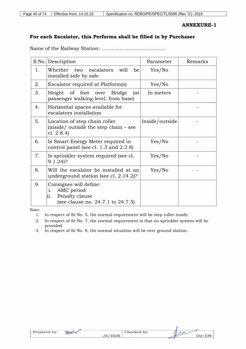
1.6 The purchaser/ user Railways shall furnish the exact information by filling in all the entries, as per the format given in Annexure 1.
1.7 The contractor’s scope of work shall include but not be limited to the
following works:-
(i) Provision of escalators including public announcement system
entry in a straight/ orderly manner; a lockable closet/ enclosure
for the controller (see Cl. 2.2.6).
vi) Provision of CCTV system in stations for passenger movements.
vii) provision of earthing pits for achieving an earthing resistance of
max 1.0 Ω
viii) LT power supply for the escalator, power supply for CCTV and
lighting circuit of escalator connected with UPS should be fed
from DG set.
ix) The level of the escalator Floor Plate should be higher than the
platform floor level by approx. 100mm or as decided by railways’
site engineer. This is absolutely essential for minimizing the
chance of rain or cleaning water running into the escalator truss.
x) To minimize the risk of passengers stumbling/ falling down due
to the two differential floor levels, railways shall ensure the
following: just after the escalator floor plate, there would be a min
315mm long stretch of anti-slip horizontal floor surface (flush
with the escalator floor plate) and thereafter, there will be an anti-
slip ramp (angle: 10o approx) descending towards the platform
floor level; this will in no way substitute/ dilute the requirement
laid down in EN-115 Cl. A2.5. The contractor will interface and
co-ordinate with the Railway and its agency(ies) undertaking the
site preparation works. The complete responsibility of interfacing
and co-ordination shall be of the contractor till final
commissioning and handing over of the escalator to the Railways.
2.0 SYSTEM DETAILS & SCHEMATICS (CONSTRUCTION)
The complete Escalator shall comprise of all parts and accessories,
which are necessary for its efficient operation, whether specifically mentioned or not. The key parts and accessories along with their functions and features are listed as follows:
2.1 Drive Unit
2.1.1 Each Escalator shall be independently driven by a geared type driving machine (or traction machine), comprising mainly of the driving
motor, a coupled Gear Box unit (for Speed reduction) and an electrically released and mechanically applied Brake (for stopping the
escalator). A VVVF converter shall control the Driving Motor. The design of the traction machine shall ensure that there shall be no oil leakage from any part of the machine under normal operating
conditions. Suitable provision for monitoring oil level in gear box shall be provided. An inspection plate/dipstick shall be provided to check the condition of the gear oil.
2.1.2 Each traction machine shall be mounted within the truss or the machine pit and shall be removable en-bloc from the truss for repair or
maintenance. Suitable lifting points shall be provided.
2.1.3 The escalator’s driving machine shall be suitable for operation on 3-phase, 415Volt ±10%, 50Hz ± 3% AC supply and it shall comply with
IS: 325/IEC 60034. OEM shall also provide suitable harmonic filters to eliminate harmonics. Ceiling limit for total harmonic distortion
(THD) shall be as per IEEE 519-1992.
2.1.4 The Contractor shall provide necessary equipment i.e. Surge protection, power filters and other necessary equipments to avoid
failure of escalator quipments on account of quality of incoming power supply. If built in filter is provided in the inverter, firm should submit necessary test reports in this regard.
2.1.5 The 3-phase Induction Motor shall be totally enclosed with external cooling fins having minimum IP-55 Protection and class F Insulation
level.
2.1.6 Average sound level of the system shall not be more than 65 dBA at 1 meter from the balustrade. The required acoustic treatment shall be
provided as necessary, to meet this requirement.
2.1.7 The overall efficiency of the combined motor and gearbox shall not be
less than 82% at full load.
2.1.8 The starting current of motor shall not exceed 3.5 times full load current. The starting current characteristic and the speed/torque characteristic
for different duty ranges shall be submitted for acceptance by the purchaser.
2.1.9 The brake shall automatically bring the escalator to a halt whenever the
power is interrupted, or any of the operating and safety switch is operated. The minimum and maximum stopping distances for the
various conditions are as follows:
a) Without load: 0.20m (minimum)
b) With full load: 1.00m (maximum)
2.1.10 A device shall be provided to prevent the starting of the escalator if the brake does not operate properly. An indicator to indicate the wearing of the brake lining shall also be provided.
2.1.11 Provisions for hand winding and the necessary tools to effect the hand winding shall be provided for each escalator.
2.1.12 Auxiliary brake should be provided in all escalators. Auxiliary brake shall always operate or close as per requirement of EN 115 latest version
2.2 Controller
2.2.1 The escalator’s motion, travel-direction, speed, stopping, etc. shall be
controlled by a compact and reliable PLC/microprocessor-based controller that is specifically designed for escalator operation. A LCD display panel and means for programming the system shall be
provided at the controller.
2.2.2 The controller shall be of a proven design and would ensure continuous-operation of the escalator over its Service-Life. The
controller shall have microprocessor based diagnostic system with
self-checking feature and provision for displaying common Faults (that may occur during the escalator’s operation) by an independent
fault-code and fault’s brief description, on an on-board and easily-visible LED/ LCD based display-unit. This would enable the
maintenance personnel to pinpoint specific fault(s) and rectify them quickly, thus ensuring minimum downtime of the escalator.
In addition, The system should also offer an additional USB port to
facilitate local data downloading facility for unusual occurrences and allow the system to be connected to a notebook, computer, Hard Disk / Pen or Flash Drive for downloading the historical data for trend
analysis. Suitable compatible driver software has to be provided to download data in excel file for analysis and presentation by Microsoft
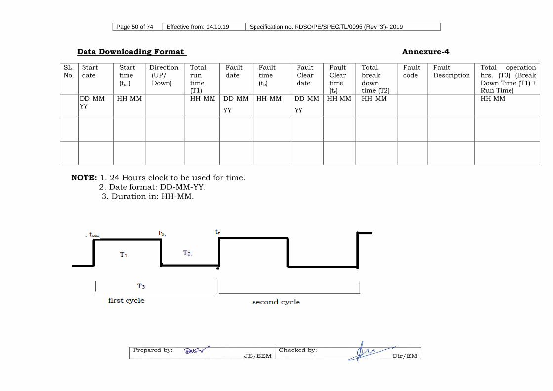
office software. The information downloaded through controller should be converted in the format attached in annexure – (4) by an application software.
2.2.3 The Escalator shall be suitable to be connected to web based monitoring software. It should be possible to monitor Escalator status
with web based application. For this purpose, the contractor shall install web based protocols along with necessary hardware in the Controller. Necessary executable files, if any, will be required to be
given free of cost by the supplier on a CD/ or any other storage device.
2.2.4 Provision for sending SMS message to minimum 10 pre-specified phone numbers for identified unusual occurrences should be
available in the controller. Provision of SIM and payment of data charges should be borne by Escalator manufacturer till Escalator is
under warranty and beyond warranty the firm undertaking AMC has to extend this facility. Firm should also provide concerned Railway free of cost facility for viewing the system performance data on the
manufacturer’s web portal until the contractual warranty period of the system. After the warranty period, the web based monitoring facility shall be available as a part of AMC.
2.2.5 The power and control wiring shall be segregated in the controller. Control circuits shall be protected by fuses or equivalent means
independent of the protection for the main circuits. All electronic components and relays shall be protected against starting and voltage surges by appropriate surge suppressers / surge arresters.
2.2.6 The escalator controller shall be housed in an IP54 protected, 1.5mm thick powder coated cabinet with hinged door (preferably of double
door design), lockable with a dedicated key. The essential operating buttons, switches, etc. shall be accessible to operations staff. Maintenance personnel would however be able to open the lock for
gaining access to the complete controller.
2.2.7 Controllers and other accessories such as incoming isolators, interface terminal boards (ITBs), switches etc. shall be placed within
a railway provided closet/ enclosure to completely bar the access of unauthorized persons. This closet/ enclosure shall be located outside
the truss. The recommended location for the closet/ enclosure shall be on the railway platform, below the escalator top horizontal portion or else below the FOB extension/ upper landing i.e. within the
columns of the FOB extension of the escalator. In as far as possible, location of the controller should be within 10m of the escalator. At
certain sites where the aforesaid is not feasible, an alternate location may be decided by railways in consultation with the contractor.
Further, wiring work including Metallic conduits/ trunking from the incoming isolators to escalator equipment shall be provided by the Contractor. Flexible PVC or similar conduit pipe shall be provided for
laying of all control wiring cables to avoid rodents and failures. The Contractor shall co-ordinate with railways for the layout of the equipment. Necessary approval of drawings shall be taken from the
purchaser.
2.2.8 If specifically asked by the purchaser energy meter should be provided
in the panel (see annexure-1 item 6). The energy meter should have following features:
a) Meter should confirm to IS 14697 and IS 15959 category-A.
meter should be capable of measuring and displaying following electrical parameters:
(i) Block load profile parameters such as KWh/ KVAh/ KVARh (Lag/Lead), maximum demand in Kw/KVA, power factor. The block period of 15/30 minutes should be
programmable by user. With block period of 30 minutes the data storage capacity should not be less than 45 days.
(ii) Daily load profile parameters such as cumulative energy
KW, cumulative KVAh, Cumulative KVARh.
b) Meter shall be provided with two ports for communication of
measured/ collected data. A hardware port compatible with USB shall be used for remote access through suitable modem (GPRS/GSM/EDGE/CDMA/PSTM/LPR) and an optical port
complying with hardware specification detailed in IEC 62056-12. This port shall be used for local data downloading through a DLMS compliant HHU. Only open source protocol will be used
for this purpose.
c) The data stored in meter shall not be lost in the event of power
failure. The meter shall have non-volatile memory (NVM), which does not need any battery back-up. The NVM shall have minimum retention period of 10 years.
d) The meter shall have 07 digits (with plus minus indication).
2.3 VVVF Converter
2.3.1 The escalator shall comprise of a VVVF converter (variable speed control), functionally integrated with the escalator controller to control the driving motor. On installation, this shall ensure the escalator’s
movement and speed control, viz - starting and normal speed of the escalator on detecting the incoming passenger(s), crawling speed (less than 0.2 m/sec) in the absence of passengers and/or stoppage after
predetermined time (Adjustable from 2 to 30 minutes). Speed in maintenance mode should be less than 0.2m/s.
2.3.2 The VVVF Converter shall also control the acceleration/ de-acceleration during the motor starting/ stopping for reducing/
limiting the starting current and the frictional wear and tear of the brake liner.
2.3.3 The controller shall have, apart from VVVF drive, a star delta starter to work as standby of VVVF convertor.
2.3.4 Test report and technical documents of VVVF drive need to be
submitted for scrutiny. Preferred make of VVVF drive are Yaskawa, Fuji, Monarch, Toshiba and Emerson. Other make will also be accepted.
2.4 Truss and Track
2.4.1 The escalator shall be provided with Structural steel truss or girder
designed to support the escalator’s dead weight which shall include any exterior claddings and decking extensions plus passenger load. Passenger loading shall be assumed as 5,000 N/m2. The truss shall also
be designed to support an additional load of the outer cladding panels and truss claddings up to a minimum load of 150N/m2. The truss
design for IR must ensure that for an escalator vertical rise up to 5m, there is no need for intermediate support. Truss shall be supported at both ends and one intermediate support (if rise is more than 5.0 meter)
with resilient pad and bearing plates. Resilient pad shall be designed for the purpose of preventing the transmission of noise and vibration to the station structure.
2.4.2 The truss design shall also ensure required safety to sustain the Steps and running Gear in operation. In the event of failure of the track
system, it shall retain the running gear in its guides.
2.4.3 The construction and design of truss shall be such that it allows for easy inspection of the interiors of the escalator.
2.4.4 Maximum deflection of Truss shall not exceed 1/1000th of the distance between supports (distance between the supports for this purpose being not less than that corresponding to a 5m vertical rise
of escalator without intermediate support).
2.4.5 Cladding of the truss shall be done with 1.5mm thick SS 304. In case
two escalators are adjacently installed, the outer cladding of intermediate balustrade should not be provided. The space between two balustrades should be properly covered by 1.5mm thick SS 304
sheet (See annexure-1).
2.4.6 The truss of escalator shall be hot dip galvanized up to minimum
thickness of 80μm. Other parts inside the truss such as track, return station, shaft etc. shall be given suitable anti-corrosive treatment with zinc plating/ painting or similar process.
2.4.7 The track system shall be constructed of steel with zinc plating. The track surface shall be straight and smooth. All joints, where possible, shall be diagonal across the width of the running surface. Maximum
deflection of track system shall be designed not to exceed 1.00mm between any two adjacent track supports under 6,000 N/m2. Anti-
jump track above step roller will restrain step up-lifting near comb area on both landings.
2.4.8 The step roller track and the chain roller track wearing surfaces shall be of minimum 5mm and 3mm thickness on the passenger and return
side respectively.
2.5 Balustrade
2.5.1 The escalator shall be provided with a solid inclined balustrade on its
each side, having adequate mechanical strength and rigidity.
2.5.2 The Interior and Exterior Panels shall be fixed in a manner to withstand the stresses and impacts expected during operation and
use of the escalator at its full capacity. The balustrade height shall be minimum 1000mm.
2.5.3 Material of the skirting shall be SS 304 having thickness of 2.0 mm for skirt panels and 1.5 mm for remaining panels.
2.5.4 The parts of the balustrade facing the steps shall be smooth and flush.
2.5.5 (a) The balustrade shall be designed to withstand the forces as per the requirements of EN-115. Moreover, the interior panel, skirting and
the skirt deflectors also shall withstand the forces as per the provisions of EN-115.
(b) Suitable provision shall be made in the balustrade for dampening
of noise and vibrations. This is done by providing coating of noise and vibration dampening material. In underground stations, the coating is required to be of fire resistant material.
2.5.6 Suitable materials or suitable type of lining shall be provided underneath the deflector device in order to achieve a coefficient of
friction as per the provisions of EN 115. If firm submits test reports from third party for coefficient of friction as required by EN-115 without use of lining same will be acceptable.
2.5.7 Appropriate measures shall be taken to discourage people from climbing on the outsides of the balustrade, if there is a danger of people falling from them. This work will fall in railways’ scope.
2.5.8 For escalators adjacent to walls, access restriction devices shall be provided. Where handrail level balustrade decking is provided between
escalators and adjacent walls, anti-slide devices shall be provided. These works will fall in railways’ scope.
2.6 Handrail and Handrail Drive System
2.6.1 The escalator shall be provided with black color handrails made of, high-quality, fire retardant, water-repellant, either synthetic rubber or
PU material, having long-durability. The minimum breaking strength of handrail joint shall be greater than 25kN or as per latest requirement of APTA. The firm needs to submit factory test report for
the joints of the handrails with validity of five years. The hardness of the outer stock shall not be less than Shore 70 A0 for rubber and 85 A0 for PU. The manufacturer should provide a guaranteed life of 04
2.6.2 The handrails shall move in the same direction and at a speed with a tolerance of – 0% to + 2% relative to the actual speed of the steps.
2.6.3 The handrail drive system shall be provided with guides immediately before and after the drive wheel. The returning portion of the handrail
shall be supported by guide rollers at not more than 2.0 m interval. For guidance of handrail at newels, guide rollers shall be provided. Adequate provisions shall be provided to maintain proper tensioning
throughout the service life of the handrail and prevent tightening/loosening and excessive heating up of the handrail during operation. The temperature rise of the handrail during operation shall
not exceed 6ºC above station ambient temperature.
2.6.4 The handrail shall overlap sufficiently with the handrail decking (top
deck), to prevent pinching and trapping fingers or hands due to running clearance. The lips at the handrail shall be of sufficient rigidity to prevent the handrail from being easily removed from the
handrail guides by a force of 300N.
2.6.5 The material of handrail guide shall be SS 304.
2.6.6 Appropriate action shall be taken to prevent the buildup of static electricity in the handrail.
2.7 Step Tread
2.7.1 The escalator Steps shall be made of corrosion-proof Casting-grade Aluminum Alloy, having sufficient mechanical strength and good construction to fully satisfy the intended purpose of their use i.e.
carrying the peak load of passengers without distortion.
2.7.2 Each step shall be supported on four wheels, two of which shall be
the step chain, wheels and shall be capable of carrying the basic load with the safety factor as per clause no. 10.11. Individual step loading shall be assumed as 6,000N/m². The design of the mounting of all
wheels on the step shall ensure that the centre line of the wheel shall remain perpendicular to the running track under all the load conditions. Step dimension shall have a tread width of at least 400
mm deep and not more than 210 mm high.
2.7.3 The step shall be one piece, pressure die cast, high wear and corrosion
resistant aluminum alloy. The step casting shall bear a marking, which clearly indicates the month and the year of manufacture.
2.7.4 The step shall be type tested according to EN 115 (Latest version).
2.7.5 The tread surface of each step shall be slotted in parallel-direction to the travel of the steps.
2.7.6 Yellow demarcation as per EN-115 should be made on the steps.
2.8 Main and Step Chains
2.8.1 The drive unit shall be connected to the main chain wheel (attached
to the main shaft) with a duplex chain of minimum safety factor 8. The Main Shaft shall further drive the Step Chain Bands.
2.8.2 The Step Chain Band shall be of endless roller type located on both
sides of the moving steps. Minimum step chain strength for up to 10m
escalator rise will be 200kN. For escalator rise above 10m and up to 18m, minimum step chain strength will be 300kN.
2.8.3 The chain rollers/wheels shall have durable elastomeric materials bonded to a metal die case hub. The shore hardness of the tyre
materials shall be 92o ± 3oA when cured. The bond shall have sufficient strength to avoid de-tyring under all load conditions.
2.8.4 The location of step chain roller:
i. If escalator rise is more than 11meters, step chain with outside roller only to be used.
ii. If escalator rise is less than 11meters, Zonal Railway may decide
to accept step chain with inside/outside rollers (see annexure-1 item 5). For very heavy footfall, e.g. Mumbai suburban area,
outside rollers may be preferred.
2.8.5 The nominal diameter of chain roller shall be 100mm (roller outside)/ 75mm (roller inside). The roller shall have a nominal width of 25 mm.
2.8.6 Each Step Chain shall be provided with an integrated Tension Device to ensure its proper tension under varying load conditions.
2.8.7 Bearing should be sealed type and shall have a design life of at least 110,000 operating hours under operating conditions. The step chain pin pressure of all escalators shall not exceed 20N/mm2.
2.9 Automatic Lubrication Device
2.9.1 The escalator shall comprise of an in-built automatic lubrication device, to lubricate the main driving-chain, step-chain and handrail
chain automatically, which can ensure their smooth-operation for a long period and thus shorten the maintenance downtime.
2.9.2 Corrosion resistant, oil tight drip pans of galvanized sheet shall be provided for the entire length of the truss. Drip pans shall be designed to collect and drain off both oil from the chain and water that may
enter through the landings, floor plates, exposed portions of escalators or from fire suppression systems. All gaps shall be properly overlapped/ sealed to prevent leakage. Means shall be provided to
drain and collect any excess lubricating oil from the chains to removable container(s) at the lower landing machine pit for easy
removal and cleaning.
2.9.3 Guards shall be provided at the truss adjacent to the main drive chain, handrail drive chain and step chain to reflect oil splatters from
the chains back to the oil drip pan. No oil splatter shall be allowed to get onto the truss, the back of the outer cladding panels, the outside
of the truss and brakes. There shall be no oil spillage through the outer panels, claddings or the truss to the surrounding areas. Proper means shall be provided to prevent the problem of oil spillage on to
machinery spaces, step risers and step surfaces.
2.9.4 Lubricants shall be selected on the basis of maintaining the highest possible flash point consistent with effective lubrication. The duration
between two successive lubrications shall be adjustable from 15 to 150 hours of operation of the escalator.
2.14.2 Cables to be used for escalator application should comply with following requirements:
(A) All cables except those within the enclosed controller shall comply with following requirements:
i. Power and control cables shall be rated for 1000V and 600V grade respectively.
ii. The conductor shall be of stranded conductor composed of
plain annealed copper wire complying with IEC 60228, Class 2.
iii. The insulation shall consist of an extruded layer of cross-
linked polyethylene complying with IEC 60502.
(B) The cable used for escalator installed at elevated station shall meet
the following requirements:
i. The flame propagating criteria of US IEEE Standard 383, with a minimum test short circuit time of five minutes, in the IEEE
Standard 383 test.
ii. IEC 60332 Parts 1 and 3, Category B, tests on single and
bunched cables under fire conditions.
iii. Limiting Oxygen Index of at least 30, to ASTM D 2863.
iv. A temperature index (TI) of 260°C to ASTM D 2863.
v. All insulation is to be moisture and heat resistant, with temperature ratings appropriate to the application conditions, and in no case lower than 90 0c for continuous operation and
250 0c during short circuit condition (for 5 second).
(C) The cable used for escalator installed at underground station shall
meet the following requirements:
i. London Transport Executive Three Meter Cube Smoke Emission Test, using optical measuring instruments. The
maximum value of absorbance AO (ON), AO (OFF) shall be 0.8 & 1.2 respectively.
ii. The US National Bureau of Standard Smoke Chamber Test,
used to evaluate plaque samples of materials of constant thickness. (NFPA-258 Smoke Generation of Solid Materials
1982). The maximum specific optical density shall be 170 under the non-polluted condition.
iii. When a sample of the cable is subjected to a combustion test
for the determination of the amount of halogen acid gases (other than hydrofluoric acid) as set out in IEC 754 - Part 1,
the halogen acid evolved shall not exceed a maximum of 0.5%.
2.14.3 All electrical equipment supplied and installed shall at least have the following class of protection for dust and water:
Machine: IP 55 Controller: IP 54 Isolating switches: IP 55
2.14.4 In general, bolt, nuts, shims and other hardware should be zinc
plated. Fasteners visible to the public shall generally be of stainless
steel. The generally applicable engineering principle will be that
fasteners shall be equal to or of greater corrosion resistance than the
most corrosion resistant metals being fastened.
2.14.5 All contactors, relay contactors and safety switches shall comply the
requirements of EN 115 and confirm to EN 60947-4-1, EN 60947-5-
1 respectively.
2.14.6 Insulation resistance between conductors and earth shall be as per
the provisions of EN 115.
2.14.7 Cross-sectional area of the conductors of safety circuits shall comply
with EN 115.
2.14.8 Safety related connectors and devices shall be of plug-in type which
can be extracted without the use of a tool and shall be impossible to
re-insert them incorrectly.
2.14.9 RCCB should be used instead of MCCB.
2.14.10 Wiring should be done as per latest edition of BIS-732 code of
practice for electrical wiring installations.
2.15 Grease/ Oil/ Dirt and Water (separate) Collector & Drainage Sumps
Separate collector and drainage sumps for loose/ falling/ accumulated
– Grease/ oil/ dirt and water shall be provided in the escalator, at its lower return station, to ensure the escalator’s cleanliness w.r.t. these elements and thus, prevent any likely hazard due to them.
2.16 Design criteria and Submittals
2.16.1 Design criteria
The design shall generally meet the following criteria: -
a) Application of state of the art technology
b) Service proven design
Escalator should be designed for life of 30 years. The service life
of components (in years) should be as given bellow:
Steps 15 Relays, timers and control gear 8 Handrail drive system 15
Step chains and step axles 15 Tension carriage assembly 15 Main drive assembly 15
Emergency brake assembly 15 Step and chain rollers 8
Handrail 4
Specific components that need to be replaced in between should be listed out and should be mentioned in the maintenance
manual, with expected life after which they need to be replaced.
A.2 Clause-by-clause confirmation of compliance to/ deviation from this specification.
A.3 Technical information asked for in Cl. 8.0
B. The contractor (successful bidder) will submit following drawings, designs, data and type test reports to the testing agency for approval during type test:
B.1 Fully dimensioned layout in plan and elevation indicating
component locations, structural supports, access spaces, Transition radii at upper and lower end and point of entry.
B.2 Loads on supporting members, reaction points and loads, and deflections under full load. Contractor shall be responsible that these parameters are within safe limits and shall provide the
supporting calculations.
B.3 Truss FEM analysis shall be submitted for the following two cases: 5m rise without intermediate support; and for maximum
rise involved in the contract with intermediate support (if rise is more than 5m). The FEM analyses should report the deflection,
stress and the factor of safety thereof. Along with FEM analysis, detail of the truss members such as dimensions and material composition should be submitted by contractor.
B.3.1 Ultrasonic testing of weld at 08 critical locations [The escalator truss is composed of three segments. Top landing, bottom landing and inclined section. The inclined section and two horizontal segments (Top landing, bottom landing) are welded at 08 locations and at these locations ultrasonic testing need to be done to check the quality of weld] should be compulsorily done. Apart from above mentioned 8 critical locations 25% of balance welds will be
tested with MPT/DPT.
B.3.2 Only MIG welding should be used.
B.3.3 In case of tubular truss, radiographic test should be done for all
welds including above mentioned 08 critical locations.
B.4 Drawings incorporating dimensions and material of comb, comb
plate, landing plate, balustrades, deck, skirt panels, track system and supports, must be submitted.
B.5 Type test reports of steps, main drive chain, handrail drive chain,
motor, gear box, step chain, handrail, step roller, chain roller, controller and cable. Dimensions and material of components if mentioned in RDSO specification should also be supported by
Drawing of components.
B.5.1 Factory test report for deflection of landing plate, skirt yield test,
balustrade panel deflection test, truss and track deflection under full load should be submitted. These tests should be witnessed by inspecting agency during type test.
B.6 Technical data of VVVF drive system, Main switch, Relays, contactors, sensors, safety devices & switches, push button,
signage and key switches. Firm will also submit technical details
of comb plate, step drive system handrail drive system relevant shafts tension devices, brake system auto lubrication system.
B.7 Layout of electrical system including motor, control panel; disconnect switches directional start and stop key switches;
emergency stop switches and covers; scheme for electrical grounding of escalator; light fixtures and control devices; schematic diagram including single line power diagram of the
escalator system, control wiring diagram and sequence of operation, indicating interface connections.
B.8 Calculation for life of bearings, size selection of power cable, UPS
backup, safety factors of step chain, main drive chain, deflection of landing plate, deflection of balustrade panel, deflection of skirt,
motor capacity selection, track deflection.
B.9 Details of fire protection system.
B.10 Type test report of fully assembled escalator.
B.11 EMI/ EMC compliance of controller.
C. The contractor (successful bidder) will be required to submit following Operation and Maintenance Manuals to the purchaser and testing agency (one searchable soft copy and one hard copy per station):
C.1 Drawings, installation and maintenance instructions, and other
data pertinent to the components used in escalator systems, including detailed repair data for all components, including
disassembly, inspection/ gauging/ torque requirements, inspection and testing schedules, reassembly, testing methods and other related information. Manuals shall cover all mechanical
and electrical components, operating panels, controls and indicators. Exploded view drawings shall be included to facilitate repair and maintenance functions.
C.2 Bill of Materials (BOM) for each escalator. The BOM will be a list of all assemblies, subassemblies and replacement components/
parts of the escalator mentioning make and model number. This detail will be required in the future for placing orders on the OEM for individual replacement parts and for other managerial
purposes.
C.3 Detail of service centers and maintenance organization including contact details, qualification and number of employees.
D. The contractor (successful bidder) will be required to submit the following information in respect of safety factors and safety implication of failures: D.1 Strength and safety factor in respect of main drive chain and step
chain
D.2 MTBF (mean time between failures) in respect of fail-safe circuits,
as called for in EN-115
D.3 Short technical note, highlighting the escalator sub-system
D.4 Short technical note listing the failures whose simultaneous
occurrence can lead to accident situations. Steps that can be
taken to avoid such accident situations.
E. The contractor (successful bidder) will submit Electrical/ Mechanical calculations for the sizing of driving machine, motor and brake to the purchaser/testing agency for approval
F. The contractor (successful bidder) will submit detailed calculations for the brake. This will include: braking distance and deceleration rate for all loads from no load to the machinery rated load, and for up and down
directions.
G. General requirements:
G.1. All type test reports should be from ILAC or NABL/NABC
approved labs.
G.2. The documents and test reports other than English should be
submitted in authenticated English translation.
G.3. The Type Test reports should mention make and model number of the products. It is responsibility of firm to establish traceability
of products supplied to Railway matching with type test reports.
G.4. The documents submitted should be serial numbered and annexed as per sequence of RDSO specification clauses. Each
page should be signed and stamped by the firm’s authorized signatory. Summary of documents submitted should be available
in separate sheet as an index in following format which shall be updated with every submission of documents:
S. No. RDSO spec. clause no.
Documents type/description
Page no. Remarks
From To
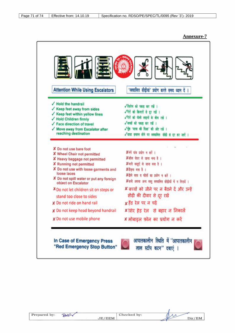
2.17 SAFETY SIGNS
2.17.1 The contractor should provide safety instructions board as per annexure-7. All signs shall be written in clearly legible characters in
trilingual in non-Hindi speaking area and in bilingual in Hindi speaking area (as the location of display board shall be decided by the
purchaser) at both top and bottom landings.
2.17.2 The following mandatory signs shall be provided by the contractor and fixed at locations and as per dimensions approved by Zonal Railways:
i) “Small children shall be held firmly” ii) “Dogs shall be carried” iii) “Use the handrail”
iv) “Push chairs not permitted” v) “Heavy luggage not permitted”.
3.0 SYSTEM OPERATING CONDITIONS
The escalator shall be able to make use and operate at the under-mentioned power supply conditions. Power supply shall be made
available by Indian Railways near the escalator installation point:
a) For power supply: AC 3-phase, 415Volts ± 10%, 50Hz ± 3%.
b) For lighting supply: AC Single-phase, 220Volts ± 10%, 50Hz ± 3%.
4.0 INFRINGEMENT OF PATENT RIGHTS
Indian railways shall not be responsible for infringement of patent rights arising due to similarity in design, manufacturing process, use
of the components used in design, development and manufacturing of escalator and any other factor which may cause such dispute. The responsibility to settle any such issue lies with the Contractor.
5.0 GOVERNING SPECIFICATIONS
The escalator shall comply with the following Standards:
EN-115: safety rules for construction and Installation of escalators
and passenger conveyers.
IS-4591: Code of practice for installation and maintenance of
escalators.
Note: Latest version of the above standards shall be applicable.
6.0 SERVICE CONDITIONS
6.1 The escalators shall be installed at the notified Railway stations all over
India and shall be able to perform under the service conditions prevailing
there.
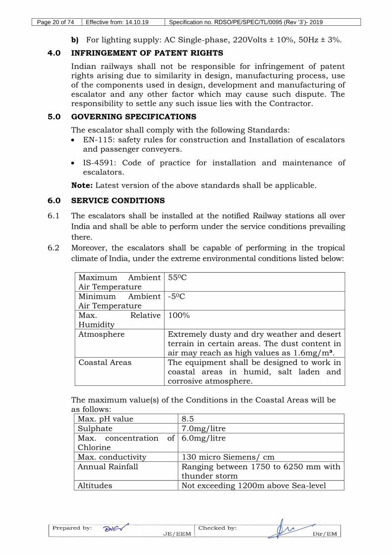
6.2 Moreover, the escalators shall be capable of performing in the tropical
climate of India, under the extreme environmental conditions listed below:
Maximum Ambient
Air Temperature
550C
Minimum Ambient
Air Temperature
-50C
Max. Relative
Humidity
100%
Atmosphere Extremely dusty and dry weather and desert
terrain in certain areas. The dust content in air may reach as high values as 1.6mg/m³.
Coastal Areas The equipment shall be designed to work in
coastal areas in humid, salt laden and corrosive atmosphere.
The maximum value(s) of the Conditions in the Coastal Areas will be
as follows:
Max. pH value 8.5
Sulphate 7.0mg/litre
Max. concentration of
Chlorine
6.0mg/litre
Max. conductivity 130 micro Siemens/ cm
Annual Rainfall Ranging between 1750 to 6250 mm with thunder storm
Operating and safety devices conforming to the following requirements shall be provided:
9.1.1 Motor Overload & Thermal Protection Device
a) The driving motor shall be protected against excessive current due to either overloading or short-circuiting by means of a suitable
device to be submitted for approval of the purchaser. Such protective devices shall be provided for each phase of the motor winding. Suitable provisions shall be made for protection against
single phasing, unbalance loading and any other abnormal condition. After the intervention of this safety device, the power
supply to the motor shall be disconnected and it shall only be possible for a competent person to reset it back to its normal working condition.
b) If the detection of excessive current depends upon a temperature increase in the motor winding, such a device may be automatically reset after the fault is removed and the winding cooled down
sufficiently, but shall not restart the escalator automatically.
9.1.2 Starting switch
Spring return key operated starting switch with running directions marked on the faceplate shall be provided at both ends of the escalator. These switches shall be positioned to enable the operator,
when using the key to start the escalator, to see the entire escalator. The key shall be removable only in the neutral position.
9.1.3 Service Stop Switch
Service switches shall be provided within the machinery spaces at both ends of the escalator. The switches shall be conspicuously and
permanently marked and located such that switching can be accomplished without passing or reaching over any part of the machinery. The operation of these switches shall disconnect electrical
power to the controller and the drive mechanism and shall activate the brakes. The switch shall be rated to interrupt the starting current
of the motor and the fuses shall be rated for the available fault current at the switch. Inspection run shall also be prohibited.
9.1.4 Emergency Stop Switch
Recessed type, momentary pressure, emergency push button stop switches with extended sleeve to protect against accidental operation
shall be provided on each escalator. A minimum of one switch shall be located in conspicuous and accessible positions at the incline section or at the newel at both ends of the escalator. The switch
provided at the incline portion shall have protection from the dust ingress. The distance between the switches shall not exceed 15 m for the escalators, otherwise, additional switches shall be provided. The
operation of these switches shall disconnect electrical power to the drive mechanism and activate the brakes(s). It shall not be possible to
start the drive mechanism by the use of these switches. Proper signage shall be displayed so that the location of the switch can be easily
identified.
9.1.5 Speed control device
Speed control device shall be provided which disconnects electrical
power to the drive mechanism and activates the brake, should the speed of the steps exceed the rated speed by more than 20%.
The speed control device is not required in cases where alternating current induction driving motors are used, provided the slip does not exceed 10% and the motor is directly connected to the drive
mechanism.
9.1.6 Broken step chain safety device
Devices shall be incorporated as part of each tension carriage which
shall disconnect electrical power to the drive mechanism and activate the brake if the step chain breaks or if the tension on either chain
drops below (or exceeds) a predetermined value, or if the motion of a chain is interrupted.
9.1.7 Broken drive device
Where the drive mechanism is connected to the main drive shaft by chains, a device shall be provided which will disconnect electrical
power to the drive mechanism and shall activate both the operational brake, and the additional brake in the event if the driving chains fail or excess sagging.
9.1.8 Non Reversing Device
A device shall be incorporated to detect reversal from the pre-set direction of motion and activate the operational and auxiliary brakes
to stop the escalators.
9.1.9 Handrail Finger Guard Safety Device
Detection device shall be provided at points where the handrails enter the escalator newels. These devices shall disconnect electrical power to the drive mechanism and activate the brake in the event of an object
entering the gap between the handrail and newel.
9.1.10 Step and Skirt Safety Devices
Detection devices shall be provided in escalator skirting panels in close proximity to the upper and lower comb plate tips, on the track system at the upper and lower curves and at 7.5 m intervals along the
incline of each escalator. Electrical power to the drive mechanism shall be disconnected and the brake(s) applied should any one of these devices be activated due to the skirt panels being forced away from
the steps.
9.1.11 Comb plate safety device
Safety devices shall be incorporated at both sides on the comb plates at each landing, which shall disconnect electrical power to the drive mechanism and activate the brake should any object become wedged
between the comb and the step. The device shall be able to operate in the horizontal and vertical direction.
9.1.12 Step Lowering Device
Devices shall be provided which will disconnect electrical power to the
drive mechanism and activate the brake, should a step be lowered due to excessive load or breakage. The detection shall be effective at the left, centre and right side of the step. The device shall be located near
the top and bottom curves for the escalators. These shall be located such that the lowered steps stop in front of the comb in order to prevent further damage.
9.1.13 Inspection Control
Inspection control complying with BS EN115 shall be provided at both
landings.
9.1.14 Missing step detection device
Detection devices shall be provided to stop the escalator before the
missing step opening appears on the passenger side of the escalator.
9.1.15 Handrail Speed Detection Device
Each handrail shall be fitted with a device, which shall stop the escalator when the handrail speed deviation exceeds the limits prescribed by EN-115.
9.1.16 Broken Handrail Device
Each handrail shall be equipped with a mechanically operated electrical safety device of approved design to detect undue tension,
excessive elongation and handrail failure.
9.1.17 Floor plate safety device
Safety switches of approved design shall be provided underneath each hinged floor plate at both the upper and lower landings. The escalator shall stop when the floor plate is opened unless under maintenance /
inspection mode.
9.1.18 Step up-thrust device
Safety device of approved design shall be provided at the upper and
lower landings to stop the escalator, should a step be lifted or displaced against the “up-thrust” track at the transition curve from
incline to horizontal in the passenger carrying side of the track system.
9.1.19 Dress Guard
Brush type deflector device shall be provided along the step nose line on the skirt panel to keep feet and loose clothing clear of the possible
trapping point and safety against garments such as Saree, loose clothes, etc. The brush bristles shall be made of fire resistant nylon filaments with split ends to give a soft face.
9.1.20 Brake Lining Safety device
Details of safety device shall be submitted for design review by the purchaser and same shall be provided at each shoe of the machine
brake to monitor the lining thickness and to detect any abnormal or uneven wear of brake lining.
9.1.21 Phase Protection Device
A phase protection device shall be provided in the controller to prevent
setting in motion or to stop the escalator in the event of phase failure or phase sequence reversal of the power supply. An illuminated visual indicator shall be provided on the control cubicle/controller to signify
the actuation of this device due to phase failure or phase sequence fault. The indicator shall remain illuminated until the fault is rectified.
9.1.22 Earth leakage protective device
An earth leakage protective device or residual current device shall be provided such that any dangerous earth leakage to the escalator
metalwork shall cause immediate stopping of the driving machine and disconnection of the power supply/ controller. The return to service shall not be possible, except if it is reset manually by a competent
person.
9.1.23 Low Oil Level Detecting Device
A low oil detection device based on the principle of ‘oil level detection’ or ‘oil pressure detection’ shall be provided to prevent the re-starting of the escalator after a predetermine time as recommended by the
manufacturers but in no case more than one week when low oil level is detected. Grease shall not be used for chain lubrication. Detailed proposal shall be submitted for review and approval of the purchaser.
9.1.24 Interface with Fire Protection Systems
All escalator supplies will include the provision of smoke detection
system in the escalator at appropriate locations e.g. machine room, pit, controller, etc. At stations provided with fire protection systems, if escalator would be utilized for evacuation purposes (in this regard,
please refer NFPA130 for more details), then the escalators should be equipped with a sprinkler system, Sprinkler heads (outlets) in the landing pits/ machine rooms and sprinkler pipes along the Truss. The
Contractor shall provide sprinkler pipes and heads inside truss for the Escalators and shall co-ordinate with railways and make adequate
provision to incorporate all the required fire protection equipment and to get the sprinklers provided in the landing pits and machine rooms connected to the main Fire Sprinkler/ Suppression system. Extension
of water supply connection to the Sprinkler pipes of Escalator from the nearest Fire Hydrant/ Sprinkler hydrant will be done by railways,
for which necessary interface will be the responsibility of Contractor. Unless the tender document specifically asks for the aforesaid sprinkler system, it will be deemed that the same is not required (see
Annex 1 item 7).
9.1.25 Water Flooding Detection Device
The lower pit of all escalators shall be provided with detection device,
such as float switch, to stop the escalators if the pit is flooded. Pit depth should be minimum 1500mm.
a) A suitable public announcement system should be provided to
announce reprogrammable safety massages such as “while riding on the escalator kindly hold the handrail firmly” etc. The speaker shall
be provided at suitable locations in the escalator itself or at locations specified by purchaser. The volume of the instructions should be adjustable. It should be possible to increase or decrease the number
of audio instructions to be played or modify the audio instructions as per requirement of purchaser. Contractor will not be liable for any extra payment in this account. The instructions shall be provided on
“Chip”. The “Chip” will be in the scope of the contractor.
b) In addition the escalator contractor shall provide passenger guidance
/ Do’s and Don’ts for the use of escalators in suitable video format which can be played on the screen provided in the station public areas. Details of the playable format will be finalized during design stage.
9.1.27 CCTV system:
A CCTV system with at least two cameras will be installed for the
surveillance of escalator working area from bottom landing to top landing. If required, more than two cameras may be installed.
9.2 Monitoring and Fault Diagnostic System
a. A microprocessor based monitoring and fault diagnostic system to provide information on the operation, identification and display of all faults that have caused the escalator to stop including
emergency stops shall be provided. The system shall be able to record at least 1000 events in their order of occurrence and display
them sequentially in a last in first out sequence. b. An alphanumeric display unit indicating the fault code and fault
message shall be installed at an easily accessible and protected
location on the handrail decking at both the landings. c. The display of the last fault can only be reset after the fault causing
the stop is cleared but the historical record shall remain in the
microprocessor. d. The system shall capture, display and retain this information
related with faults in the controller memory. This information should be downloaded and converted by application software as per format attached in annexure (4).
9.3 Following is a summarized list of critical safety features. All of these will be supplied and installed by the contractor.
SN Safety devices/ features required
Description
1. Emergency stop device In an emergency, it stops escalator
immediately, if pressed
2. Comb plate safety device It stops escalator, if objects are caught between
21. Step missing device It stops escalator, if the Step is missing
22. “START” Buzzer device It alerts the passengers when escalator starts
working/ moving
23. “WRONG-ENTRY” alarm device
It alerts the passengers, if they approach to enter the escalator from a Wrong entry-point/
opposite- direction to its movement-direction, by sounding the warning-buzzer and beginning the escalator movement in its pre-set, correct
direction.
24. “AUTO-START” on passenger-approach device
It ensures the stopped-escalator to start operating/ moving after detecting the approaching passengers by a 3-D scan.
25. Oil-water separator &
drainage system
It ensures separate collection & disposal of the
loose/ falling oil/ grease and accumulated water and thus preventing a potential hazard.
26. Grounding of escalator (limited to making earth
connections to escalator)
As per IS 3043:1987
27. Smoke Detector It stops escalator, if smoke generates under pit,
machine room and controller.
28. Sprinkler System An optional item (see Cl. 9.1.24)
29. Low Oil Level Detecting Device
See Cl. 9.1.23
30. Float switch It stops the escalator if the lower pit is flooded
Note: Each bidder must submit their compliance or deviations in a
“Compliance Statement”, as well as, the specific details related to their escalator-design, against each safety device/ feature mentioned above.
10.0 GENERAL REQUIREMENT
10.1 The complete escalator system shall be reliable and conform to the latest version of the International/ EN-115 and National/ IS-4591
standards.
10.2 All materials used in manufacturing the escalator, shall be fire-retardant and not easy to ignite. All cables and conduits should be of
fire retardant material.
10.3 All power devices and electro-mechanical units including the drive unit,
controller, and converter etc. to be used in the escalator shall be suitable for a heavy-duty application of a Public Service escalator as per above Standards.
10.4 All mechanically moving parts of the escalator shall be completely enclosed within imperforate panels or walls, except the accessible Step
treads, part of handrail and permitted apertures for ventilation.
10.5 In case of escalator installation location being directly exposed to the weather/ extreme atmosphere, a proper roof-covering and enclosure must
be provided by Indian Railways.
10.6 The balustrades shall not have any parts that would tempt/ allow any
person to stand on the same. The balustrades interior panels shall be smooth and shall not have any protruding part or sharp edged covering strips etc.
10.7 The balustrades design and construction shall provide for adequate mechanical strength and rigidity, such that the vertical force distributed over the Handrail surface/ length shall not be able to cause any
permanent deformation, breakage or displacement of any balustrade part(s) as per the provisions of the standard EN-115 clause 5.5 meant
for this purpose.
10.8 At the landings of the escalator, a sufficient unobstructed area shall be available to accommodate the passengers as per the provisions of the
standard EN-115 clause A2.5 meant for this purpose. Similarly a clear height of minimum 2.30m or more shall be available above the Steps of
the escalator at all points, as per the provisions of the standard EN-115 clause A2.1 meant for this purpose.
10.9 All of the escalator’s equipment, structures and other metallic parts
shall be effectively grounded by the contractor to the incoming earthing conductor to be provided by railways. The earthing arrangements will be as per the standard practice conforming to IS: 3043.
10.10 Heavy duty Escalator design shall be such that no major repair shall be necessary for a period of at least fifteen (15) years from the date of issue
of 'Certificate of Taking Over', assuming that regular inspection and maintenance are carried out in accordance with the manufacturer's recommendations. Major repairs shall consist of repairs to the major
components like steps, track system, step chains, main drive system, traction machines, landing plates and tension carriage due to causes other than those attributable to normal wear and tear.
10.11 Safety factors used in the design shall, as a minimum, conform to the following:
a. Trusses – As per EN 115 (as applicable for Public Service
Escalators)
b. Step roller tracks and steps - 8.
c. Driving Machinery - 8 for steel and bronze components; 10 for
cast iron parts.
d. Chains – 8.
e. Any other item (if not specified elsewhere) – As per EN 115 (as
any independent/ reputed/ national test agency/ lab’s certification in this regard.
12.0 TESTING & INSPECTION
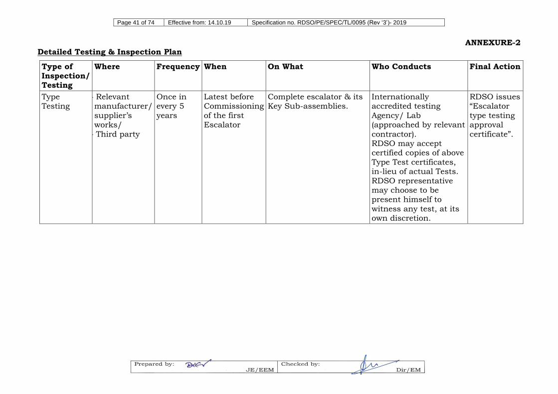
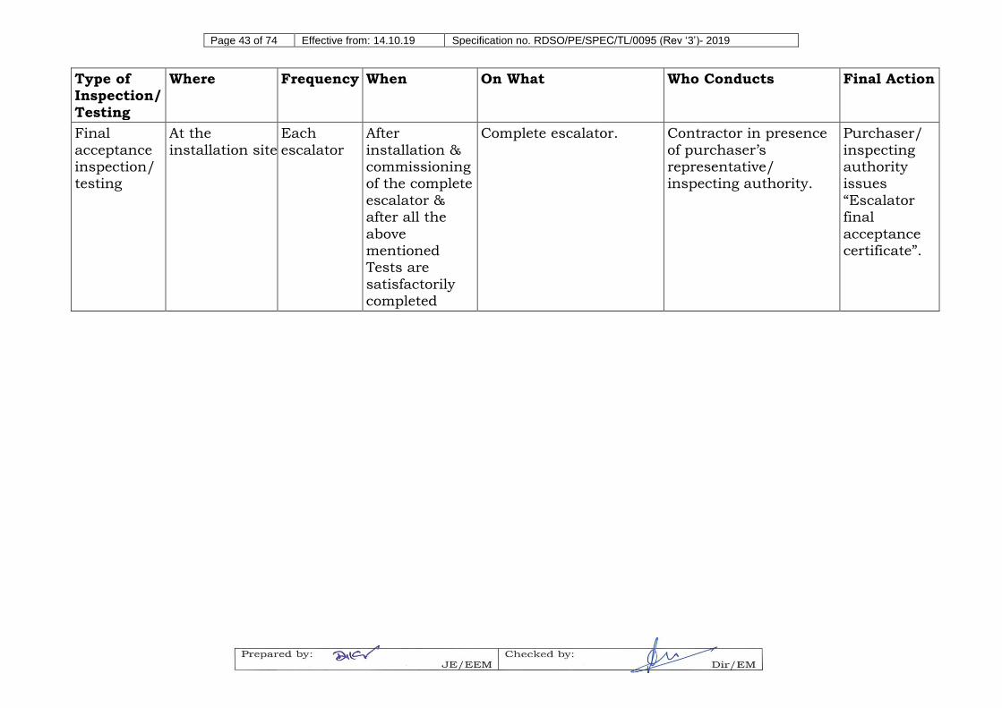
Testing & inspection plan stages and details are as given in the table in
Annexure-2.
12.1 Escalator Type Testing
12.1.1 For type testing of escalator the Contractor shall submit a
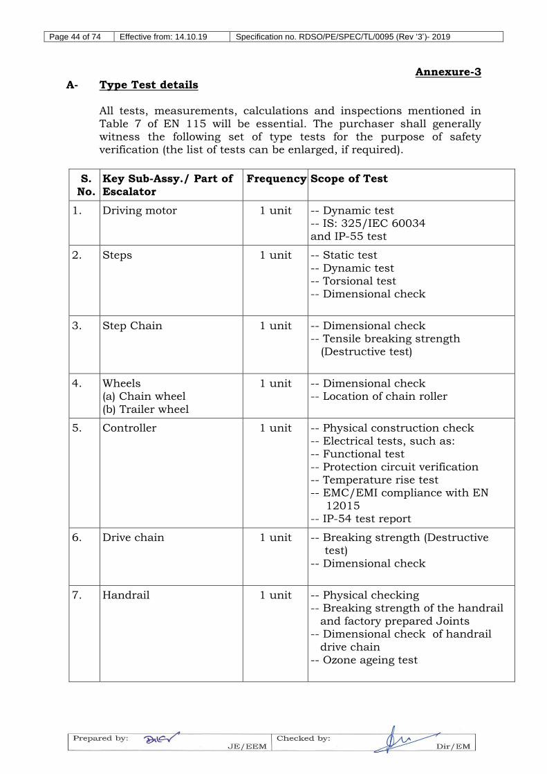
comprehensive type testing protocol that includes the requirements laid down in EN–115, IS–4591 and Annexure-3 of this spec., to RDSO for approval.
12.1.2 Further, the contractor shall submit the available type test reports in respect of tests listed in the protocol; these reports should pertain to
the systems and sub-systems that are to actually form a part of escalators to be supplied to IR. The contractor should also submit an action plan for carrying out the remaining type-tests.
12.1.3 If the product is being manufactured initially in a foreign country, RDSO representative at its discretion may like to visit and witness any
of the Type Tests, lodging and boarding charges will be borne by vendor/Railway based on RDSO’s general policy about these issues. The Contractor shall co-ordinate the program, in such case.
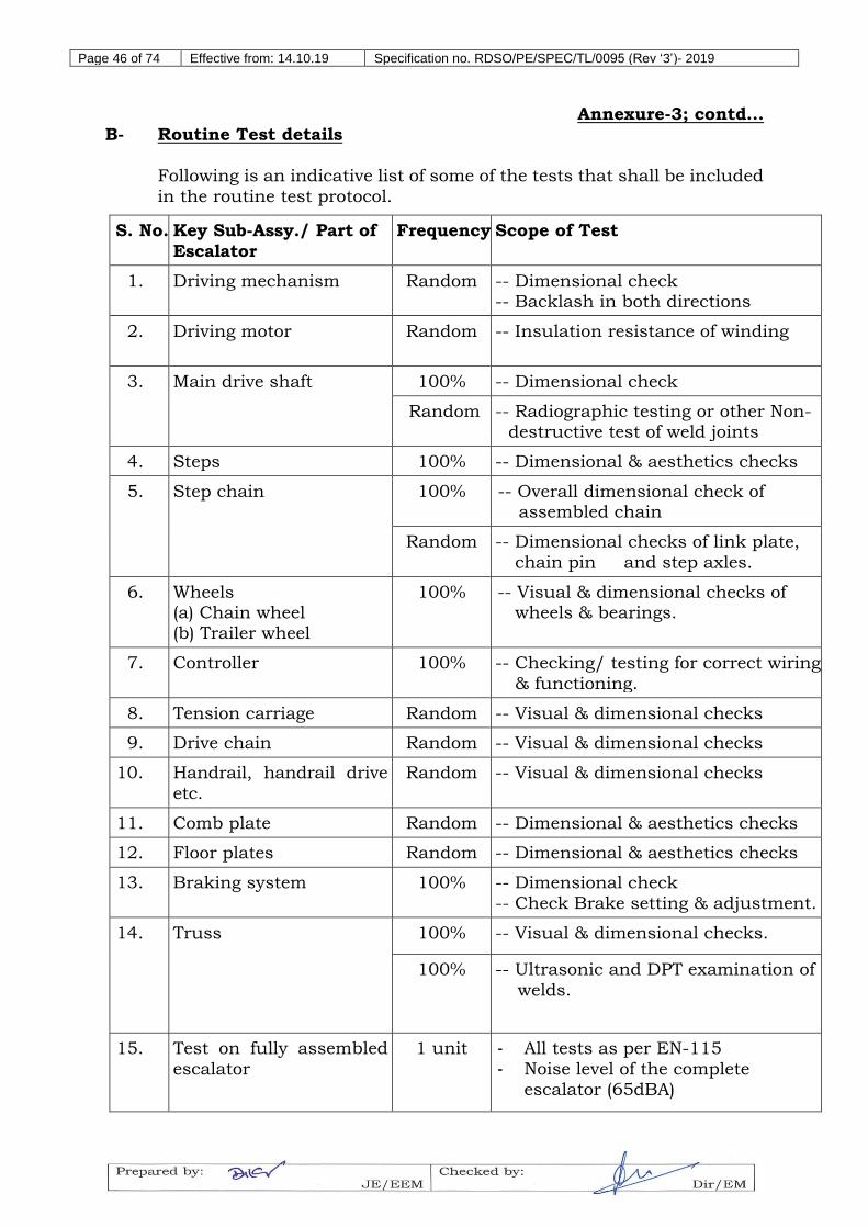
12.2 Escalator Routine Testing
12.2.1 At first, the Contractor shall submit a comprehensive routine testing protocol that includes the tests in the nature of routine tests as are
mentioned in EN–115, IS–4591, Annexure-3 of this spec. and any other relevant tests, to inspecting agency for approval.
12.2.2 Routine testing entails tests and inspections that are conducted at the works of escalator manufacturer and/or the works of its key sub-suppliers, as per the relevant standards.
12.2.3 The purchaser’s representative/ inspection agency would have the right at its discretion, to witness routine Test(s) of the complete escalator/ its Key Sub-assemblies, during the escalator’s
manufacturing and/or accept the test results/ reports of their respective manufacturer’s/ supplier’s in-house quality control
(reports should be furnished for systems and sub-systems that are to actually form a part of escalators to be supplied to IR), as sufficient evidence of the execution of these routine tests.
12.2.4 At least 3 weeks’ notice shall be given to the purchaser’s representative/ inspection agency to be present for the routine testing
and inspection.
12.2.5 If the Product is being manufactured initially in a foreign country, purchaser’s representative/ inspection agency at its discretion, may
like to visit and witness any of the routine tests, at their own cost. The Contractor shall co-ordinate the program, in such case.
12.3 Escalator Pre-Dispatch Verification of Packing List
12.3.1 Before the ordered goods (complete escalator system kits), as per the offered dispatch lot are dispatched, purchaser’s representative/
inspection agency shall verify completeness of the dispatch lot as per order details/ contractor’s packing list and if everything is in order,
issue the “Dispatch approval certificate”.
12.3.2 Thereafter, the Contractor can dispatch the goods to the consignee.
13.0 ESCALATOR INSTALLATION AND FINAL ACCEPTANCE INSPECTION/ TESTING
After installation, the escalator shall be tested by the Contractor in the
presence of the purchaser’s representative/ inspection agency. The important tests to be conducted are listed in Annexure-3 of this spec. for guidance. The test protocol will be submitted to RDSO for approval.
After satisfactory completion of inspection/ testing, the purchaser’s representative/ inspection agency will authorize the commissioning of
the escalators for public use by issuing the “Escalator installation final acceptance certificate”.
14.0 WITHDRAWAL OF APPROVAL
Approval granted to the Contractor is liable to be withdrawn in the event of noticing any major change at a later date in the design or major
change from the Bill of material as approved earlier without seeking the Prototype approving authority i.e. Production Units’/ RDSO's approval or using any major Sub-assembly of inferior specification/ quality, thus
compromising with the reliability.
15.0 LIGHTING
15.1 The escalator and its surrounding area shall be sufficiently and
adequately illuminated by Railways, especially in the vicinity of the comb to ensure safe and comfortable ride of passengers. Light intensity
on tread surface shall be minimum 50 lux or more as per IS 4591.
15.2 Machine room, pit and controller enclosure shall be provided with suitably protected permanent light fixtures, electrical outlets,
mechanical or natural ventilation and suitable access.
15.3 The electric lighting installation and the socket outlets shall be independent of the power supply to the machine being fed by a separate
cable from the main switch as per the provisions of the standard EN-115 clause 5.8.3 meant for this purpose.
15.4 The contractor shall provide Comb lighting, step gap lighting and traffic direction lighting. The step gap lighting shall be of green color. The step gap lighting shall be provided so that the passengers can adjust their
feet on the step and it shall be provided under the steps near the comb plate at each landing. All the lightings shall be water and dust proof.
Comb lighting shall be supplied through a UPS with battery back-up. The UPS and battery will be supplied by the contractor and the system will be sized for 30 minutes backup for the lighting.
16.0 ACCESSIBILITY
16.1 The escalator design shall allow easy and safe accessibility on both sides, to authorized persons for Inspection, maintenance and repairs.
16.2 Driving and return stations, machinery spaces inside the truss and also separate machinery spaces, shall not be accessible to unauthorized
persons. Hence, lockable Inspection and trap doors shall be provided.
17.0 MOVEMENT OF MATERIAL
Completely assembled escalator or its sub-assemblies (which cannot be handled by hand), shall be:-
a. Equipped with fittings for being lifted/ moved by a lifting device, or
b. Designed in a way, to allow the attachment of above type fittings, e.g., threaded holes, or
c. Designed/ shaped in a way, to allow easy attachment to the lifting
device or transportation means.
18.0 INSTALLATION& COMMISSIONING
18.1 All works at the installation site shall be carried out in accordance with the standard acceptable methods and practices of installation of escalators and electrical equipment.
18.2 All equipment, sub-assemblies, structures, truss, etc. shall be installed as per their respective sub-contractor’s installation instructions.
18.3 Special care shall be taken of leveling/ plumbing, which shall be done meticulously before any equipment, sub-assembly or structure is fixed finally in position.
18.4 Adequate care shall also be taken during installation of the complete Escalator to avoid damage to any equipment, sub-assembly or building structure.
18.5 Indian railways will be responsible for major civil work needed for installation and commissioning of escalator at designated platform. The
Contractor will provide a terminal board near escalator and Railways will provide electrical wiring and earthing up to this terminal board. Railways will provide site assembly area with proper power connection
as per the extant rules. For more details on railways’ scope of work, please see Cl. 1.8.
19.0 LABELING AND MARKING
19.1 All equipment and apparatus, inside or outside the switchboard, including instruments, meters and relays shall be labeled or marked adequately.
19.2 In addition, warning labels shall be fitted at all points, where the removal of covers/ panels may expose live equipment, operating above 50V between circuits or to earth and shall bear the inscription ‘Danger- Live
Parts’ in red color that is clearly visible from a viewable distance.
20.0 PACKING, SHIPPING AND DELIVERY
20.1 All equipment shall be properly inspected before the Shipment. An inspection tag bearing the word “INSPECTED” or “PASSED” giving details of the inspection date, etc. shall be attached to the Packaged
Consignment. All four sides of the packaged consignment shall contain details of the Consignee & Consignor.
20.2 Appropriate caution notices such as “Fragile” or “Handle with care” etc shall be displayed on the outside surface of the boxes, crates and
packages.
20.3 The Contractor shall be responsible for the safe transportation and
delivery of materials to the location, as specified by the purchaser.
20.4 Accessories:
Each escalator shall be provided with the following accessories:
a. Two sets of maintenance barriers b. Two sets of starting keys. c. One hand-winding tool per escalator (if applicable).
d. One set of hand lamp. e. One set of inspection boxes with cable per escalator.
f. One set of floor plate opening tools. g. Two sets of inner panel opening/removal tools per station. h. Two sets of keys for controllers.
21.0 ON-SITE SUPPORT TO CONTRACTOR
21.1 The purchaser/ user railways would extend facilities on free-of-charge
basis, to the Contractor for storing: the product; installation, testing and commissioning equipment/ tools/ accessories, etc., at a suitable location, as close as possible to the installation site.
21.2 This shall include providing a separate lockable/ secure material-storage cum Site office with telephone, electrical supply/ light and fan fittings, etc.
22.0 WARRANTY
22.1 The Contractor shall be responsible for any damage to equipment
provided in the escalator, due to defective design, materials, workmanship for a period of 24 months from the date of commissioning of escalator and 30 months from the date of supply, whichever is earlier.
The Contractor shall attend to the complaint (including replacement of defective components, if required) within 12 hours from the time of receipt of complaint at his own cost.
22.2 The period of warrantee will be extendable in case of recurring problems of defective design, material or manufacturing. The Contractor shall
warrant that everything to be furnished hereunder shall be free from all defects and faults in material, workmanship and manufacture and shall be of the highest grade and consistent with established and accepted
standards of material of the type ordered and in full conformity with specifications and drawings. The Contractor’s liability in this respect of
any complaints, defects and /or claim shall be limited to furnishing and installation of replacement parts, free of any charge. The warranty clause in commercial agreement, if any, shall prevail.
22.3 The Contractor shall be responsible for carrying out all the modifications at his cost on any part of the equipment during the period of warranty required for satisfactory operation of the equipment as per technical
specification. For any technical decision the final authority from the purchaser’s side is RDSO.
22.4 All the replacements and repairs, that the purchaser shall call upon the Contractor to deliver or perform under this warranty, shall be delivered
and performed by the Contractor promptly and satisfactory.
22.5 The warranty period would cover comprehensive maintenance inclusive
of all spares, material and labour cost.
22.6 During warranty period, in case the escalators become non-functional due to any manufacturing defect, then the escalator would be
considered under breakdown and the Contractor would be required to rectify the defects.
22.7 The consignee shall ensure that the records of breakdown are
maintained on a shift basis. 22.8 The Contractor shall ensure that in case a failure is reported by a
consignee, qualified Service Engineers shall visit the site within 12 hours from the time of complaint. This period of 12 hours after the failure report shall be treated as grace period, which will not count
towards breakdown time. Complaints shall be lodged by consignee by fax, phone, e-mail or per bearer at address given by the Contractor.
23.0 AFTER SALES SERVICE
23.1 The bidder shall indicate in the offer, the facilities available with the bidder or local agent for providing the required after sale service during
warranty and post warranty periods. The bidder will also mention service organizations located in India and the availability of trained staff and maintenance spares etc.
23.2 The Contractor shall provide and ensure servicing facilities throughout the warranty period of the system. After the warranty period is over, the
Contractor should give service support for trouble shooting and for obtaining spare parts for AMC period.
23.3 The Contractor shall ensure that, in case a consignee reports a failure,
qualified service engineers visit the site within 12 hours from the time of complaint. Consignee shall lodge complaints by fax, e-mail or per bearer at address given by the Contractor. The responsibility to keep
the current failure reporting address details will rest with the consignee.
24.0 MAINTENANCE
24.1 The Contractor shall provide free-of-charge, maintenance service (and all the works specified) including required spares, for the specified warranty period.
24.2 During the guarantee period, the above maintenance service shall include all preventive, scheduled and corrective maintenance and
additionally, all service-request calls made by the purchaser/ user railways.
24.3 For this, the Contractor would be required to provide a comprehensive
maintenance and service plan, for review and acceptance by the purchaser or his authorized representative.
24.4 The maintenance work-system shall ensure safety of the personnel and
24.5 In the event of any failure, requiring design modifications, etc. in the escalator, the Contractor shall undertake to submit its details for a
review by the Purchaser or its authorized representative. On reaching consensus and post-modification, the Contractor shall undertake fresh
testing and re-commissioning, if required.
24.6 It shall be possible to change the Steps without dismantling the Internal Panels or the Skirt of the escalator, to ensure minimum down time
during maintenance and repairs of the escalator.
24.7 Annual Maintenance Contract (AMC)
24.7.1 The bidder are required to quote separately for a comprehensive
annual maintenance contract (AMC) for the escalator supplied against the specification, which will be inclusive of all spares, material and
labour costs to carry out maintenance schedule as per annexure-6 and to attend all the breakdowns. The purchaser will specify the contract period for the AMC in the tender document.
24.7.2 The contractor shall be responsible to keep all the escalators along with all connected ancillary equipments/apparatus/ machines, as
have been stated under the scope of work and specification, in perfect working condition, on any day during the tenure of the contract (excepting the period of programmed shut down). In case, any
escalator is out of order, for failure/ breakdown of the escalator or of any other related/ancillary equipments/apparatus/machines, the escalator shall be attended, within a period of 12 hours of being
informed.
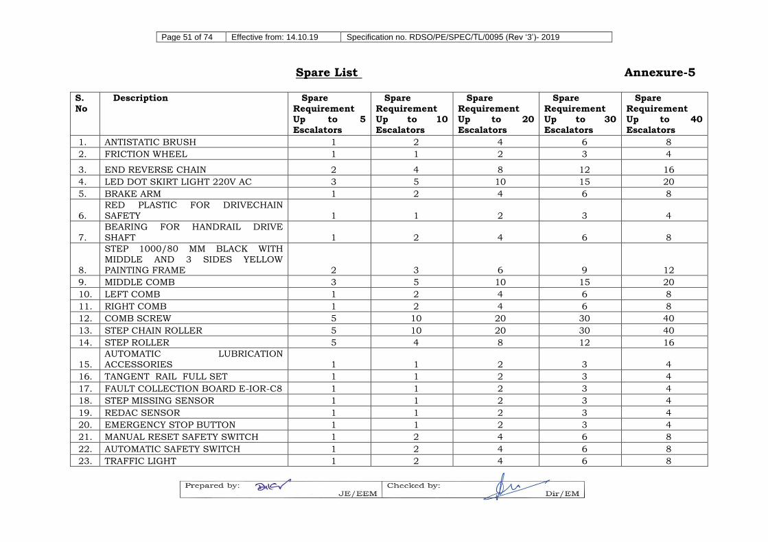
24.7.3 Firm needs to ensure availability of minimum quantity of consumable
spares at local service centers for effective maintenance of escalators based on number of escalators to be maintained as mentioned in annexure-5.
24.7.4 Firm will carry out maintenance as per maintenance schedule mentioned in annexure 6.
24.7.5 The consignees must communicate their option to enter into AMC at
least 30 days prior to expiry of warranty. The AMC agreement must be signed within six months prior from the date of expiry of warranty.
24.7.6 Maximum of 08 hours will be permitted for monthly, quarterly and half yearly schedule maintenance. For yearly maintenance 16 hour without load test and 24 hours with load test will be given to firm.
25.0 TRAINING PROGRAM
The Contractor shall fit in all training instructions/ demonstrations for
correct operation and maintenance of the escalator into a three working days self-contained training program. The contractor shall organize one training programme per 20 nos. escalators ordered. For orders less than
20 nos. escalators, at least one training programme will be organized. For orders that are not integer multiples of 20 nos., rounding off will apply (e.g. for 50 nos. escalators, 3 nos. training programmes will be
organized). The training programme(s) will be held at contractors’ head office or at any other location as agreed between railway administration
The Contractor shall provide the necessary Operators’ Training to the
Purchaser’s authorized/ designated Staff as per the formal Training Program designed for this purpose. This shall enable them to carry out
the normal/ rescue operations under normal/ emergency situations respectively as well as minor repairs by themselves.
25.2 Maintenance Training
The Contractor shall provide the necessary maintenance training to the purchaser’s authorized/ designated Staff as per the formal Training program designed for this purpose. This shall enable them to perform
minor and non-specialized maintenance of the escalators.
26.0 OPERATION AND MAINTENANCE MANUALS
26.1 The Contractor shall provide operations and maintenance manuals, for
the use by the supervisory, operating and technical staff of the
purchaser in accordance with EN-115 clause no. 7.4.
26.2 Each manual shall be divided into indexed sections explaining the
subject matter in logical steps. Soft copy of manuals should be in
searchable PDF format. The soft copy should be such that if required
by the Railways multiple copies can be made from the original soft copy
of manual.
26.3 The operations manual shall contain the principle and operations’
details of the complete escalator under the normal and emergency
conditions.
26.4 Details of the common faults that might occur in the complete escalator
&/or any of its key components/ sub-assemblies and their rectification
shall also be included.
26.5 The maintenance manual shall contain the maintenance and servicing
instructions for the complete escalators along with explanatory notes
and drawings as necessary.
26.6 The periodic maintenance schedule recommended by the Contractor for
the satisfactory performance of the escalators shall also be included.
26.7 Escalator being a critical public safety item, a draft of operations and
maintenance manual should be submitted to the purchaser for
approval with regard to its completeness and comprehensiveness. The
final version of operations and maintenance manual should be issued
on the basis of purchaser’s comments.
26.8 It is recommended that the operation and maintenance manuals be
shipped along with the escalator shipment. In any case, Operation and
Maintenance manuals are to be supplied to railways well before final
testing/ commissioning of escalators.
27.0 QUALITY ASSURANCE
27.1 The Bidder shall prepare and furnish their QA plan documentation, as per their ISO: 9000 program being followed. It shall include and clearly mention the procedures ensuring that all equipment/ materials/
All tests, measurements, calculations and inspections mentioned in
Table 7 of EN 115 will be essential. The purchaser shall generally witness the following set of type tests for the purpose of safety verification (the list of tests can be enlarged, if required).
S.
No.
Key Sub-Assy./ Part of
Escalator
Frequency Scope of Test
1. Driving motor 1 unit -- Dynamic test -- IS: 325/IEC 60034 and IP-55 test
2. Steps 1 unit -- Static test
-- Dynamic test -- Torsional test -- Dimensional check
ESCALATOR MAINTENANCE CHECK LIST – HALF YEARLY Annexure-6C
Name of service provider: DATE:
Escalator serial No: Location:
Sl. No. Description OK / NOT OK / NA Remark
A. BOTTOM PIT INSPECTION
1. Condition of INSPECTION PENDANT
2. Rigid fixing of half round ' C ' track ( Rivet & Screws)
3. Condition of half round “ C “ Track in Bottom LH & RH
B. TOP PIT / MACHINE ROOM AREA INSPECTION
4. Check the tightening of drive unit base mounting bolts ( GEAR BOX BASE mounting bolts)
5. Check the clearance between FLY WHEEL and FLY WHEEL COVER
6. Check the Gear box oil level and condition
Gear Oil changed date _____________
7. Rigid fixing of half round ' C ' track in TOP ( Rivet & Screws)
8. Condition of Half round “ C “ Track in Top LH & RH
9. Rigid fixing of TANGENT track
10. Check the clearance between Tangent track and step chain roller in 4 areas ( It should be min. 0.5mm)LH top:_____mm, LH bottom : ______mm, RH top: ______mm, RH Bottom :
11. Handrail drive chain tension adjustment bolt length should be equal in both LH & RH side (Checkparallelness of the handrail drive shaft with main drive shaft )
12. Check the Length of the handrail pressure roller Spring tension. (Should be 55 mm) __________mm
13. Check the Condition & thickness of handrail drive wheel liner ( Friction wheel liner), Thickness should be more than
8mm
14. Check the condition of sub rollers / Step guide rollers in
TOP (It should not touch with steps, minimum 0.5 mm clearance is required)
n) Landing Plate / Floor Plate – The portion of floor plate next to the comb plate at the landing.
o) Newel – The portion of the balustrade on the landing at the end where the moving handrail changes direction.
p) Number of Horizontal/Flat steps– Horizontal/ Flat steps shall be measured from the point at which the first step emerges from under the comb plate in a horizontal direction to the first exposure of the riser of
an adjacent step, both at the upper and lower landings.
q) Panel – The portion of the balustrade immediately adjacent to the moving stairway, occupying the vertical space between the steps and
the deck or inner panel.
r) Skirt – The portion of the balustrade immediately adjacent to the
moving stairway, occupying the vertical space between the steps and the deck or inner panel.
s) Step – The unit which forms the moving stairway.
t) Step chain – The main chain to which the steps are attached.
u) Step roller track – The track on which the step roller runs.
v) Step Tread – The horizontal portion of the step grooved in the direction of travel and on which the passengers are carried.
w) Step roller – The rollers attached to the step and supporting the step.
x) Truss – The supporting structure on which the various components are mounted.
y) Working point – The intersection of the escalator step nose line and
the projection of the escalator floor plate level.
z) Constant length – The horizontal distance between the escalators
working point and the end of escalator support.
Part II – Other Terms
a) Purchaser – The President of the Republic of India or the administrative
officers of the railway on his behalf.
b) Bidder – The person/firm who submits duly filled in tender documents as an offer to carry out the work specified in tender document. The
bidder can be manufacturer (single entity)/ consortium/ joint venture (one of the consortium/joint venture member could be an Indian firm
or the Indian subsidiary of manufacturer for the purpose of this tender).