16
ISSYS LP MONOAXIAL SCREW SYSTEM SURGICAL TECHNIQUE GUIDE
ISSYS LP MonoaxIaL Screw SYSteM
SurgIcaL technIque guIde


The ISSYS LP Monoaxial Screw and Staple System is a product of the ISSYS LP thoracolumbar platform making it one of the most versatile systems in the spine industry.
IMPORTANT: It is recommended that Anterior Monoaxial Screws be directed into the vertebral body in the coronal plane. Placement of Staples should be centered on the lateral aspect of the vertebral body. If the construct is too anterior, there is risk of injury to vessels and the Monoaxial Screws may enter the contra-lateral foramen. If the Staples are situated too posterior the Monoaxial Screws may enter the spinal canal. It is recommended that Monoaxial Screws be perpendicular to the lateral plane of the vertebral body to avoid inadvertent angling posterior toward the spinal canal.
IntroductIon
NOTE: The ISSYS LP Monoaxial Screw System implants and instruments are designed and tested for use only with the ISSYS LP Spinal Fixation System. (Polyaxial, Monoaxial, and Cross Connectors) This surgical technique sets forth detailed, recommended procedures for using the ISSYS LP Monoaxial Screw System implants and instruments. It offers guidance, however, as with any such technical guide, each surgeon must consider the particular needs of each patient and make appropriate adjustments when necessary and as required. This is intended as a guide only. There are multiple techniques for the application of spinal screws and, as with any surgical procedure; a surgeon should be trained before proceeding.
The ISSYS LP Monoaxial Screw System is indicated for:
Anterior (Non-Pedicular)
LI-L5
Posterior (Pedicular)
TI-SI
• DDD • Spondylolisthesis • Fracture • Deformity • Tumor • Pseudarthrosis • Stenosis
• Spondylolisthesis • Fracture• Deformity • Tumor • Pseudarthrosis • Stenosis

Staple preparation & inSertion ................................................. 1
Monoaxial Screw inSertion .................................................... 2
Vertebral body diStraction .................................................... 3
anterior rod placeMent and coMpreSSion .............................. 4
• option 1 ............................................................................ 4
• option 2 ............................................................................ 4
Final tightening ..................................................................... 5
Monoblock tranSVerSe connector .......................................... 7
Monoaxial Screw SySteM inStruMentS ...................................... 8
Monoaxial Screw SySteM iMplantS ..........................................10
tabLe of contentS

The ISSYS LP Monoaxial Screw Anterior Staples are available in small, medium, and large sizes (Rostral and Caudal) and were designed to distribute cantilever loads across the vertebral body. Using the largest staple possible is recommended to provide optimal surface contact.
• Rostralstaplesareblueandcaudalstaplesaregray.
Grasp the staple with the Staple Inserter, and tighten by sliding the outer sleeve in the distal direction. Ensure the staple spikes are facing toward the vertebral body when implanting.
IMPORTANT: Do not place the staple too far anteriorly on the vertebral body. To avoid this, surgeons should resect the rib head and retract the solis muscle, allowing a probe to pass along the posterior cortex which can be used as a guide for staple placement.
Gently impact the staple onto the vertebral body surface with a mallet. The Staples are marked anterior and posterior for left side approaches. These markings will be reversed for a right side approach. The ISSYS LP Monoaxial Screw construct is designed with a longer anterior rod, when compared to the posterior rod, for improved construct strength.
Based upon the patient’s anatomy, placing the longer rod posteriorly may be more applicable.
A trapezoid construct is stronger in comparison to a parallelogram configuration. To ensure a trapezoid, varying length rods should be used.
StaPLe PreParatIon & InSertIon (oPtIonaL)
– 1 –

After the Staples are in place (OPTIONAL) begin screw insertion. If staples are used, the screw entry point has already been prepared with the spikes of the Staple Inserter.
The Straight Awl or Angled Awl can be used for initial or futher preparation of the entry point.
For the anterior screw tracts, use the Awl to create a pathway perpendicular to the vertebral body. For the posterior screw tracts, use the Awl to create a pathway angled 10° anteriorly to avoid the spinal canal.
Next, the screw pathway is completed by advancing the Probe slowly and palpating the contra-lateral cortex before penetration.
The surgeon should feel the Probe piercing the opposite cortex. The Depth Gauge is then used to measure depth and ensure bi-cortical passage for optimal fixation.
After the pathway is prepared and the proper screw diameter and length is determined, the Monoaxial Screwdriver is used to insert the screws. It is always recommended to measure the screw length prior to insertion.
TheMonoaxialScrewsshouldbefullyseatedintotheStapleandtheScrewSaddleshouldbealignedforrodplacement.Foranterioruse,theISSYSLPMonoaxialScrewSystemislimitedtousewith5.5and6.5mmdiameterMonoaxialScrews,whichareavailableinarangeoflengths.(seeImplantOverview)
MonoaxIaL Screw InSertIon
– 2 –
Straight
Angled
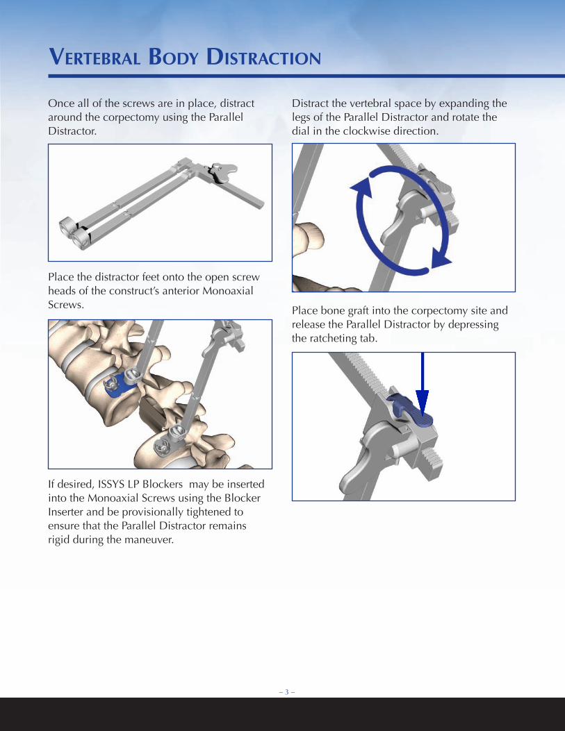
Once all of the screws are in place, distract around the corpectomy using the Parallel Distractor.
Place the distractor feet onto the open screw heads of the construct’s anterior Monoaxial Screws.
If desired, ISSYS LP Blockers may be inserted into the Monoaxial Screws using the Blocker Inserter and be provisionally tightened to ensure that the Parallel Distractor remains rigid during the maneuver.
Distract the vertebral space by expanding the legs of the Parallel Distractor and rotate the dial in the clockwise direction.
Place bone graft into the corpectomy site and release the Parallel Distractor by depressing the ratcheting tab.
VertebraL bodY dIStractIon
– 3 –
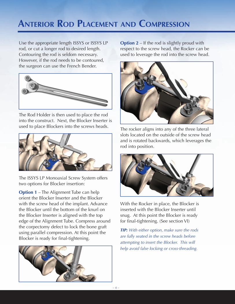
Use the appropriate length ISSYS or ISSYS LP rod, or cut a longer rod to desired length. Contouring the rod is seldom necessary. However, if the rod needs to be contoured, the surgeon can use the French Bender.
The Rod Holder is then used to place the rod into the construct. Next, the Blocker Inserter is used to place Blockers into the screws heads.
The ISSYS LP Monoaxial Screw System offers two options for Blocker insertion:
Option1 – The Alignment Tube can help orient the Blocker Inserter and the Blocker with the screw head of the implant. Advance the Blocker until the bottom of the knurl on the Blocker Inserter is aligned with the top edge of the Alignment Tube. Compress around the corpectomy defect to lock the bone graft using parallel compression. At this point the Blocker is ready for final-tightening.
Option2 – If the rod is slightly proud with respect to the screw head, the Rocker can be used to leverage the rod into the screw head.
The rocker aligns into any of the three lateral slots located on the outside of the screw head and is rotated backwards, which leverages the rod into position.
With the Rocker in place, the Blocker is inserted with the Blocker Inserter until snug. At this point the Blocker is ready for final-tightening. (See section VI)
TIP: With either option, make sure the rods are fully seated in the screw heads before attempting to insert the Blocker. This will help avoid false locking or cross-threading.
anterIor rod PLaceMent and coMPreSSIon
– 4 –
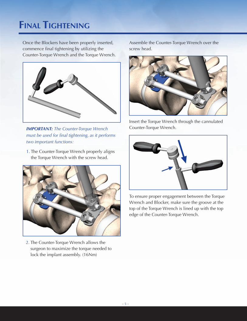
Once the Blockers have been properly inserted, commence final tightening by utilizing the Counter-Torque Wrench and the Torque Wrench.
IMPORTANT: The Counter-Torque Wrench must be used for final tightening, as it performs two important functions:
1. The Counter-Torque Wrench properly aligns the Torque Wrench with the screw head.
2. The Counter-Torque Wrench allows the surgeon to maximize the torque needed to lock the implant assembly. (16Nm)
Assemble the Counter-Torque Wrench over the screw head.
Insert the Torque Wrench through the cannulated Counter-Torque Wrench.
To ensure proper engagement between the Torque Wrench and Blocker, make sure the groove at the top of the Torque Wrench is lined up with the top edge of the Counter-Torque Wrench.
– 5 –
fInaL tIghtenIng

fInaL tIghtenIng
The ratcheting mechanism of the Torque Wrench can be rotated counter-clockwise to achieve the optimal position for leverage. Rotate the Torque Wrench clockwise while holding the Counter-Torque Wrench firmly in place.
The Torque Wrench has four groups of three arrows located around the top of the instrument, which provide visual assistance for determining the prescribed tightening torque. Prior to applying leverage, the top arrow in each group should be aligned with the bottom right arrow.
Apply leverage until the top arrow is aligned with the bottom left arrow. Once the two said arrows are aligned, the prescribed tightening torque has been applied to the Blocker.
IMPORTANT: Exceeding the prescribed tightening torque by over leveraging the arrows past the final alignment can damage the implant and/or instrument.
– 6 –
Tightened
Initial

MonobLock tranSVerSe connector (oPtIonaL)
Monoblock Transverse Connectors improve a construct’s torsional strength. Use the Caliper to determine the proper rod to rod span and which size to use.
Monoblock Connectors are available in a range of lengths as shown in the Implant Overview section. Typically, one Monoblock Connector is used per spinal motion segment. (Example: Two connectors for a one level corpectomy.) When using a Monoblock transverse connector with Monoscrews through staples, ensure monoscrews are fullyseatedin the Staples.
The17mmconnectoristheonlysizeapplicableforthisconstructconfiguration.
Place the Monoblock Connector into the rods using the Bar Holder.
Tighten the Monoblock Connector set screws with the 3mm tightener. Sequentially move from one set screw to the next, multiple times, until the device is firmly locked in place.
The gradual tightening of the Monoblock Connector will help avoid “walking“ along the rods.
NOTE: Over tightening transverse connector set screws may notch the rod or strip the set screw hex.
– 7 –
– 8–
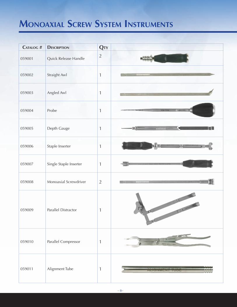
cataLog # deScrIPtIon qtY
059001 Quick Release Handle2
059002 Straight Awl 1
059003 Angled Awl 1
059004 Probe 1
059005 Depth Gauge 1
059006 Staple Inserter 1
059007 Single Staple Inserter 1
059008 Monoaxial Screwdriver 2
059009 Parallel Distractor 1
059010 Parallel Compressor 1
059011 Alignment Tube 1
MonoaxIaL Screw SYSteM InStruMentS
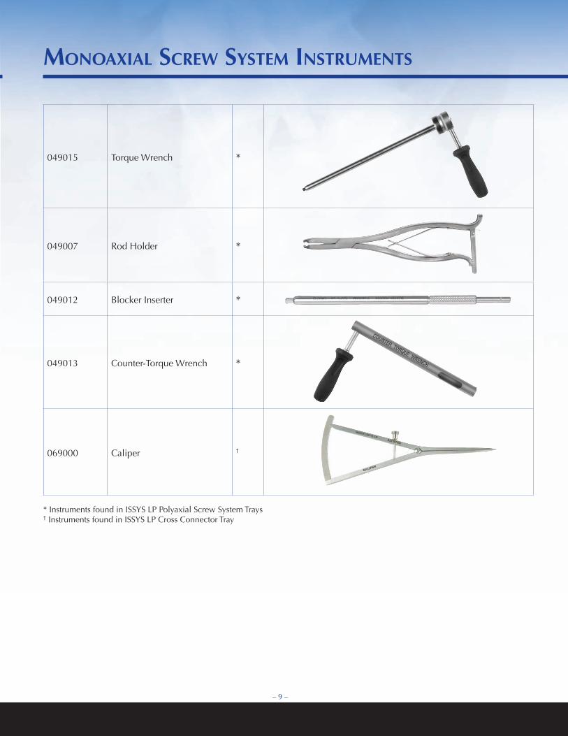
049015 Torque Wrench *
049007 Rod Holder *
049012 Blocker Inserter *
049013 Counter-Torque Wrench *
069000 Caliper †
– 9 –
MonoaxIaL Screw SYSteM InStruMentS
* Instruments found in ISSYS LP Polyaxial Screw System Trays† Instruments found in ISSYS LP Cross Connector Tray
– 10 –
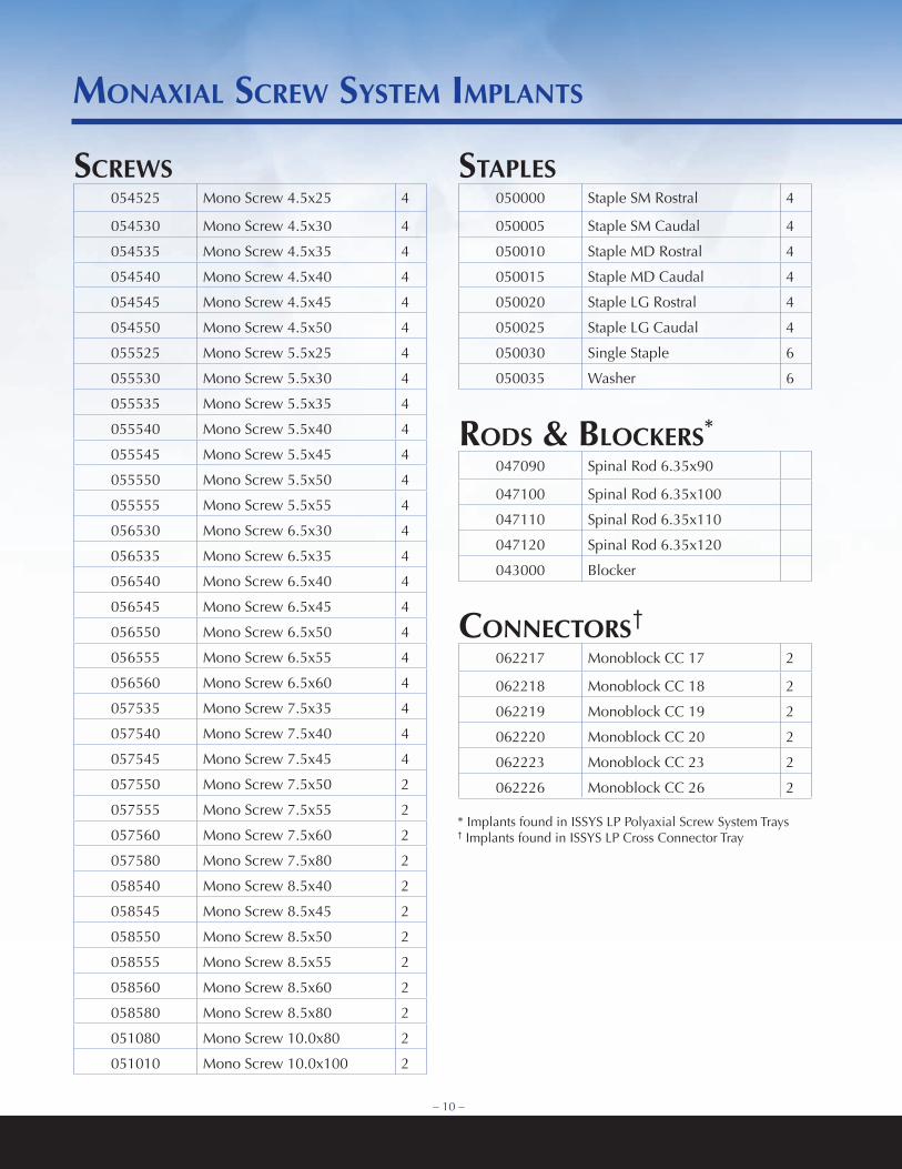
ScrewS054525 Mono Screw 4.5x25 4
054530 Mono Screw 4.5x30 4
054535 Mono Screw 4.5x35 4
054540 Mono Screw 4.5x40 4
054545 Mono Screw 4.5x45 4
054550 Mono Screw 4.5x50 4
055525 Mono Screw 5.5x25 4
055530 Mono Screw 5.5x30 4
055535 Mono Screw 5.5x35 4
055540 Mono Screw 5.5x40 4
055545 Mono Screw 5.5x45 4
055550 Mono Screw 5.5x50 4
055555 Mono Screw 5.5x55 4
056530 Mono Screw 6.5x30 4
056535 Mono Screw 6.5x35 4
056540 Mono Screw 6.5x40 4
056545 Mono Screw 6.5x45 4
056550 Mono Screw 6.5x50 4
056555 Mono Screw 6.5x55 4
056560 Mono Screw 6.5x60 4
057535 Mono Screw 7.5x35 4
057540 Mono Screw 7.5x40 4
057545 Mono Screw 7.5x45 4
057550 Mono Screw 7.5x50 2
057555 Mono Screw 7.5x55 2
057560 Mono Screw 7.5x60 2
057580 Mono Screw 7.5x80 2
058540 Mono Screw 8.5x40 2
058545 Mono Screw 8.5x45 2
058550 Mono Screw 8.5x50 2
058555 Mono Screw 8.5x55 2
058560 Mono Screw 8.5x60 2
058580 Mono Screw 8.5x80 2
051080 Mono Screw 10.0x80 2
051010 Mono Screw 10.0x100 2
StaPLeS050000 Staple SM Rostral 4
050005 Staple SM Caudal 4
050010 Staple MD Rostral 4
050015 Staple MD Caudal 4
050020 Staple LG Rostral 4
050025 Staple LG Caudal 4
050030 Single Staple 6
050035 Washer 6
rodS & bLockerS*
047090 Spinal Rod 6.35x90
047100 Spinal Rod 6.35x100
047110 Spinal Rod 6.35x110
047120 Spinal Rod 6.35x120
043000 Blocker
connectorS†
062217 Monoblock CC 17 2
062218 Monoblock CC 18 2
062219 Monoblock CC 19 2
062220 Monoblock CC 20 2
062223 Monoblock CC 23 2
062226 Monoblock CC 26 2
MonaxIaL Screw SYSteM IMPLantS
* Implants found in ISSYS LP Polyaxial Screw System Trays† Implants found in ISSYS LP Cross Connector Tray


Tel: (973) 808-0019Fax: (973) 808-0707
1140 ParsiPPany Blvd., suiTe 201ParsiPPany, nJ 07054
www.customspine.com
000230 reva issys lP Monoaxial screw sysTeM surgical Technique guide


