45
ISTANBUL TECHNICAL UNIVERSITY 1 DEPARTMENT OF GEOMATICS ENGINEERING SURVEYING WEEK 2
ISTANBUL TECHNICAL UNIVERSITY
1
DEPARTMENT OF GEOMATICS ENGINEERING
SURVEYING
WEEK 2
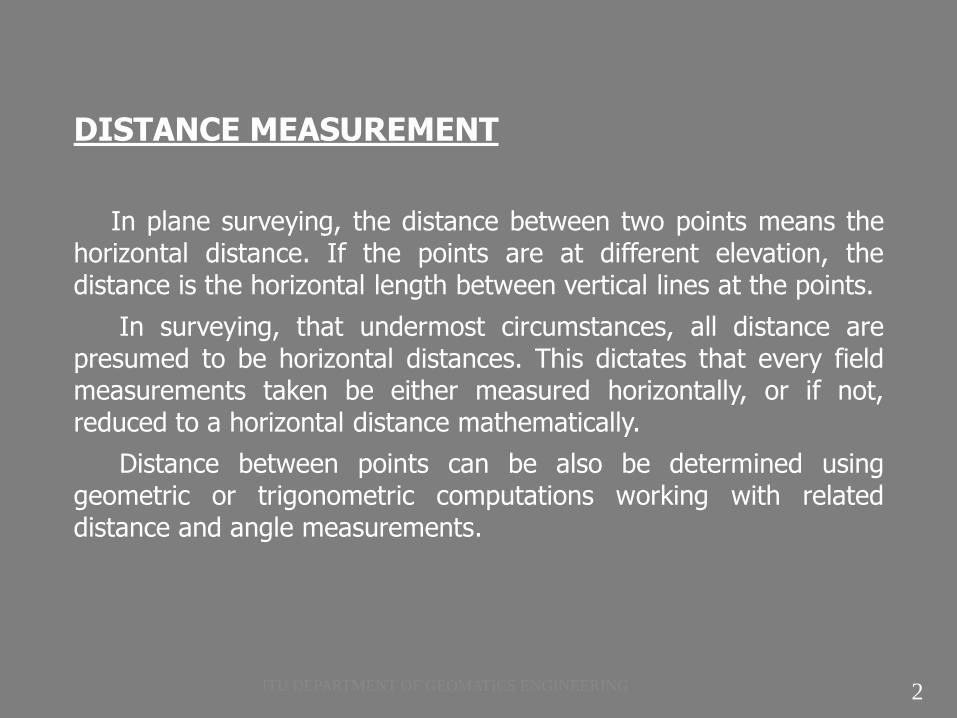
DISTANCE MEASUREMENT
In plane surveying, the distance between two points means the horizontal distance. If the points are at different elevation, the distance is the horizontal length between vertical lines at the points.
In surveying, that undermost circumstances, all distance are presumed to be horizontal distances. This dictates that every field measurements taken be either measured horizontally, or if not, reduced to a horizontal distance mathematically.
Distance between points can be also be determined using geometric or trigonometric computations working with related distance and angle measurements.
2 ITU DEPARTMENT OF GEOMATICS ENGINEERING

DISTANCE MEASUREMENT
Figure:1 (C.D. Ghilani, P.R. Wolf, 2008)
If the angle α is determined, the horizontal distance between points A and B can be computed from the relation ;
H; is the horizontal distance between points,
L; is the slope length
α; is the vertical angle from horizontal
H = L cos α
3 ITU DEPARTMENT OF GEOMATICS ENGINEERING

DISTANCE MEASUREMENT
If the difference in elevation d between the ends of the tape is measured, which is done by leveling, the horizontal distance can be computed using the following expression derived from the Pythagorean Theorem;
C is the difference between H horizontal distance and L slope distance ;
C is approximately ;
4 ITU DEPARTMENT OF GEOMATICS ENGINEERING
DISTANCE MEASUREMENT
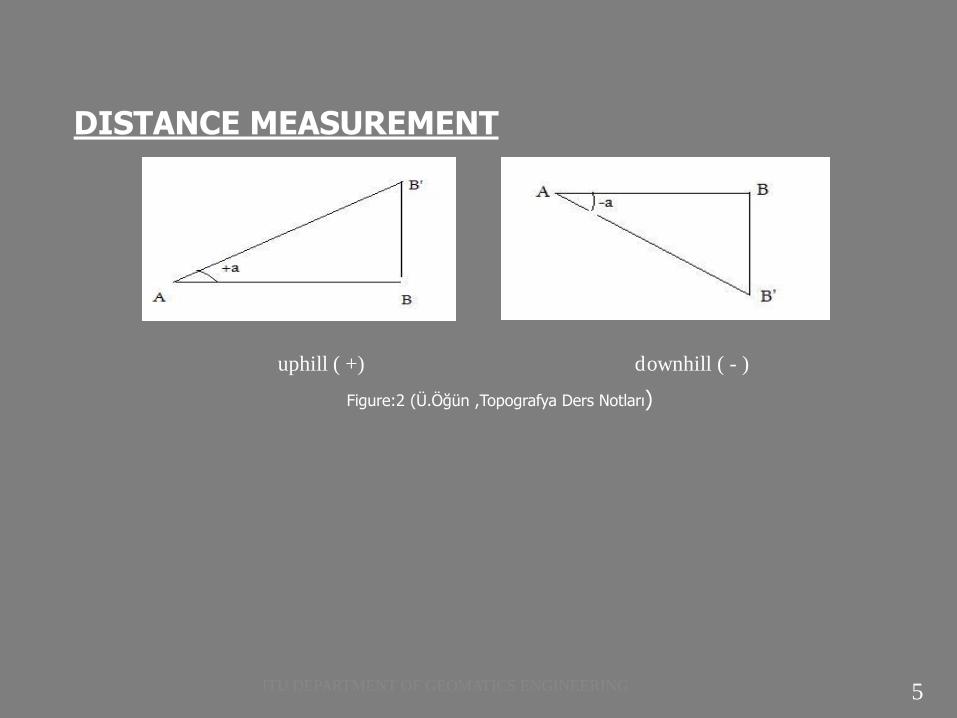
uphill ( +) downhill ( - )
Figure:2 (Ü.Öğün ,Topografya Ders Notları)
5 ITU DEPARTMENT OF GEOMATICS ENGINEERING

DISTANCE MEASUREMENT
HB = height of B
Figure:3 (U.Özerman, 2010) HA = height of A
Figure:4 (Ü.Öğün, Topografya Ders Notları)
6 ITU DEPARTMENT OF GEOMATICS ENGINEERING

DISTANCE MEASUREMENT
Methods for making linear measurements ;
There are several direct and indirect methods of determining distances.
Taping
Tacheometry
Electronic Distance Measurement
Others
Most surveying field distance measurements are accomplished by using either taping (steel or fiber glass tape) or electronic distance measurements (EDM) .
7 ITU DEPARTMENT OF GEOMATICS ENGINEERING

1.TAPING :
Taping is the linear measurement of the horizontal distance between two points using a surveyor’s tape.
Observation of horizontal distances by taping consists of applying the known length of a graduated tape directly to line a number of times.
8 ITU DEPARTMENT OF GEOMATICS ENGINEERING

Taping equipment and accessories:
Figure:6 (C.D. Ghilani, P.R. Wolf, 2008)
9 ITU DEPARTMENT OF GEOMATICS ENGINEERING

Taping equipment and accessories:
Figure:7 (H.Özener , Lecture Notes)
10 ITU DEPARTMENT OF GEOMATICS ENGINEERING

Taping equipment and accessories:
Metric tapes have standard lengths of 10, 20, 30, 50, 60 ,100 m. All can either be wound on a reel (a) or done up in loops .
Invar tapes are made of special steel to reduce length variations caused by differences in temperature.
Cloth (metallic) tapes are actually made of high-grade linen, wide with fine copper wires running lengthwise to give additional strength and prevent excessive elongation. (b)
Chaining pins (taping pins) are used to mark tape lengths .Most taping pins made of sharply pointed at one end, have a round loop at the other end, and are painted with alternate red and white bands (c) .
The hand level is a simple instrument used to keep tape ends at equal elevations when observing over rough terrain (d) .
11 ITU DEPARTMENT OF GEOMATICS ENGINEERING

Taping equipment and accessories:
Tension handles facilitate the application of desired standard or known tension.
A pocket thermometer permits reading data for making temperature corrections.
Range poles (lining rods ) made of wood, steel or aluminum. The main utility of range poles is to mark the line being measured so that the tape’s alignment can be maintained (e).
Plump bobs are used in taping to permit the surveyor to hold the tape horizontal when the ground is sloping. A graduation mark on the horizontal tape can be transferred down to a point on the ground using the plumb bob string. Also, a plumb bobs can be used to provide precise theodolite and total station sightings.(f)
12 ITU DEPARTMENT OF GEOMATICS ENGINEERING

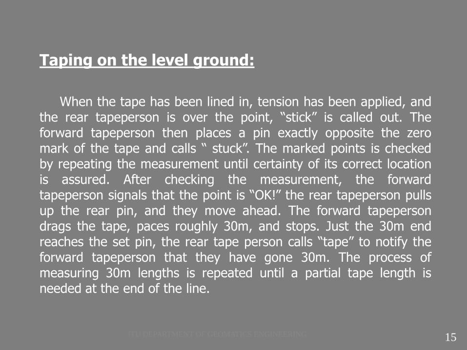
Taping on the level ground:
In many instances, it is easiest to simply measure the horizontal distance by keeping both ends of the chain (steel tape) at the same elevation. This is not difficult if there is not over long distance or so of elevation change between points.
Taping requires a minimum of two people. Using range poles, the line to be measured should be marked at both ends (in a vertical position), and at intermediate points where necessary, to ensure the unobstructed sight lines. The forward tapeperson is lined in by the rear tapeperson. Directions are given by vocal and signals.
13 ITU DEPARTMENT OF GEOMATICS ENGINEERING

Taping on the level ground:
The rear tapeperson holding the 0m end of a tape over the first (rear) point lines in the forward tapeperson, holding the other end of the tape. For accurate results the tape must be straight and the two ends held at the same elevation. A specified tension is applied.
In some case, Plumb-bob is used to hold the tape above ground in a horizontal position. Placing the plumb-bob string over the proper tape graduation and securing it with one thumb, mark each end point on the tape. The rear tapeperson continues to hold a plumb over the fixed point, while the forward tapeperson marks the length. In measuring a distance shorter than a full tape length, the forward tape person moves the plumb-bob string to a point on the tape over the ground mark.
14 ITU DEPARTMENT OF GEOMATICS ENGINEERING
Taping on the level ground:
When the tape has been lined in, tension has been applied, and the rear tapeperson is over the point, “stick” is called out. The forward tapeperson then places a pin exactly opposite the zero mark of the tape and calls “ stuck”. The marked points is checked by repeating the measurement until certainty of its correct location is assured. After checking the measurement, the forward tapeperson signals that the point is “OK!” the rear tapeperson pulls up the rear pin, and they move ahead. The forward tapeperson drags the tape, paces roughly 30m, and stops. Just the 30m end reaches the set pin, the rear tape person calls “tape” to notify the forward tapeperson that they have gone 30m. The process of measuring 30m lengths is repeated until a partial tape length is needed at the end of the line.
15 ITU DEPARTMENT OF GEOMATICS ENGINEERING
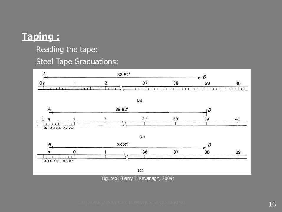
Taping :
Reading the tape:
Steel Tape Graduations:
Figure:8 (Barry F. Kavanagh, 2009)
16 ITU DEPARTMENT OF GEOMATICS ENGINEERING

Taping :
Recording the distance:
17 ITU DEPARTMENT OF GEOMATICS ENGINEERING
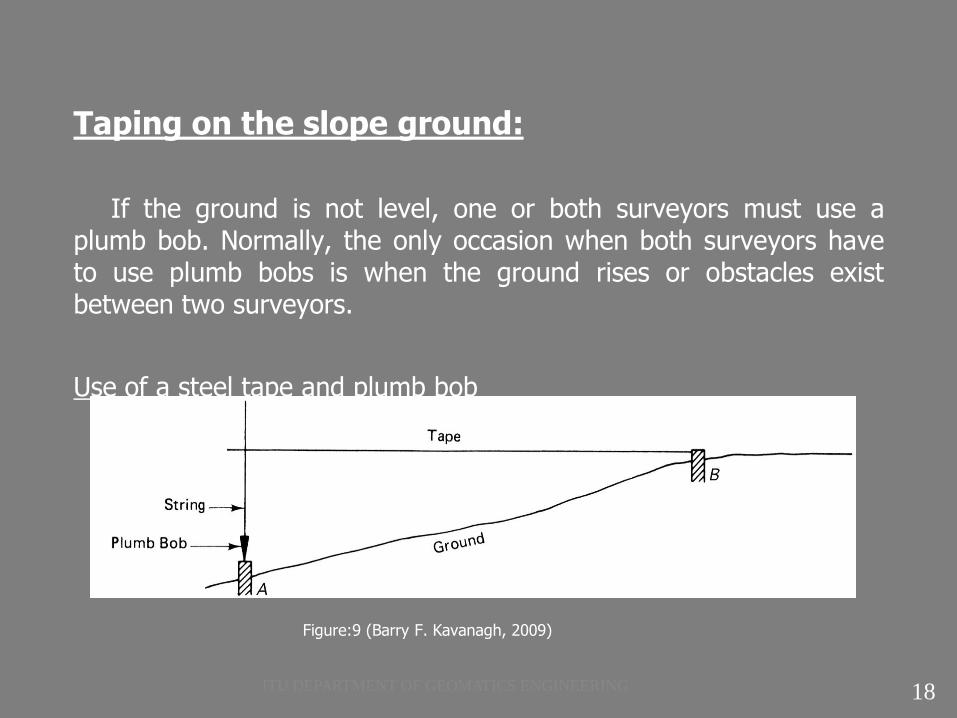
Taping on the slope ground:
If the ground is not level, one or both surveyors must use a plumb bob. Normally, the only occasion when both surveyors have to use plumb bobs is when the ground rises or obstacles exist between two surveyors.
Use of a steel tape and plumb bob
Figure:9 (Barry F. Kavanagh, 2009)
18 ITU DEPARTMENT OF GEOMATICS ENGINEERING
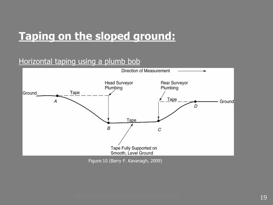
Taping on the sloped ground:
Horizontal taping using a plumb bob
Figure:10 (Barry F. Kavanagh, 2009)
19 ITU DEPARTMENT OF GEOMATICS ENGINEERING
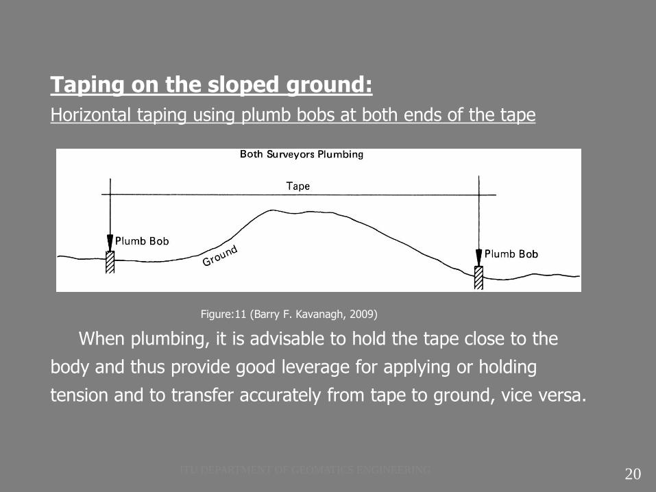
Taping on the sloped ground:
Horizontal taping using plumb bobs at both ends of the tape
Figure:11 (Barry F. Kavanagh, 2009)
When plumbing, it is advisable to hold the tape close to the
body and thus provide good leverage for applying or holding
tension and to transfer accurately from tape to ground, vice versa.
20 ITU DEPARTMENT OF GEOMATICS ENGINEERING
Taping on the sloped ground:
If the rear surveyor is using a plump bob, he or she shouts out “tape,” “mark” or some other sign that, at that instant, the plumb is steady over the mark. If the head surveyor is also using a plumb bob, he or she must wait to take a reading until both plumb bobs are simultaneously over their respective marks.
Breaking tape:
In practice, most measurements are taken with the tape held horizontally. If the slope is too great to allow an entire tape length to be employed, shorter increments are measured until all the required distance has been measured. This operation is known as breaking tape.
21 ITU DEPARTMENT OF GEOMATICS ENGINEERING
Taping on the sloped ground:
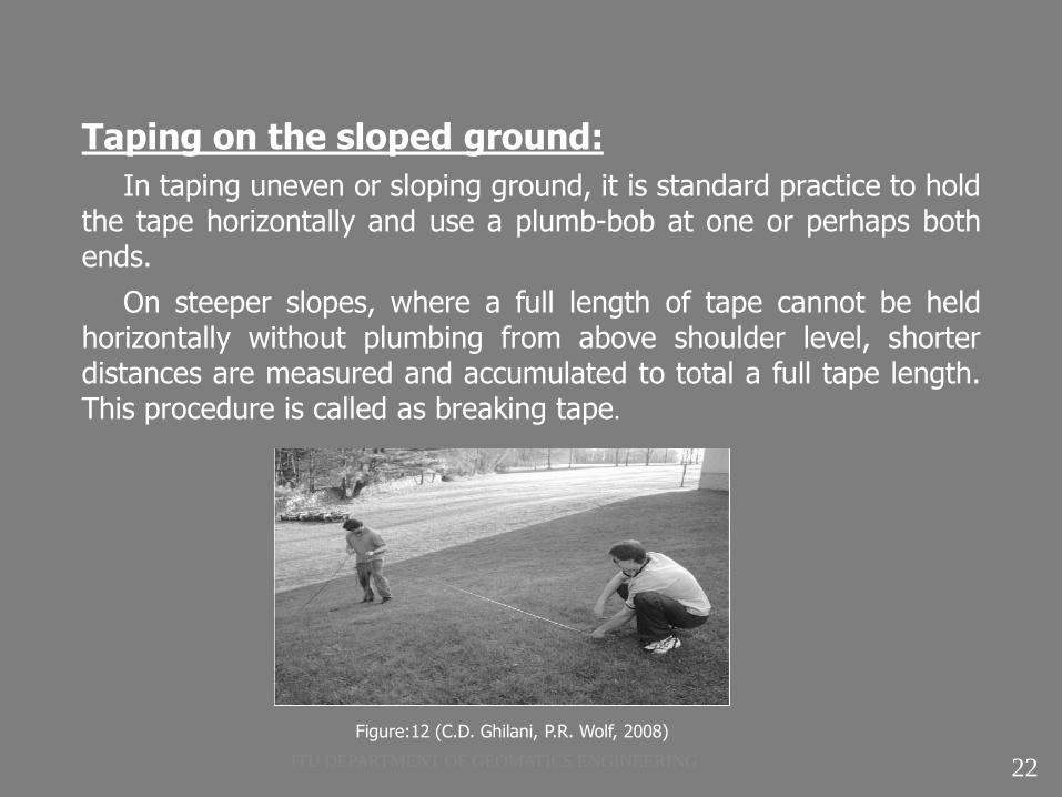
In taping uneven or sloping ground, it is standard practice to hold the tape horizontally and use a plumb-bob at one or perhaps both ends.
On steeper slopes, where a full length of tape cannot be held horizontally without plumbing from above shoulder level, shorter distances are measured and accumulated to total a full tape length. This procedure is called as breaking tape.
Figure:12 (C.D. Ghilani, P.R. Wolf, 2008)
22 ITU DEPARTMENT OF GEOMATICS ENGINEERING

Taping on the sloping ground:
Taping downhill is preferable to measuring uphill for two reason. First; in taping downhill, the rear point is held steady on fixed object while the other end is plumbed. In taping uphill, the forward point must be set while the other end is wavering somewhat. Second, if breaking tape necessary, the head tapeperson can more conveniently use the hand level to proceed downhill a distance, which renders the tape horizontal when held comfortably at chest height.
23 ITU DEPARTMENT OF GEOMATICS ENGINEERING
Taping on the sloping ground:
In some cases, it becomes impractical to break chain. When the slope becomes so steep that frequent chaining (tape) points are required, a vertical surface must be measured across, or intermediate chaining (tape) points are not readily accessible, it may be more desirable to determine the horizontal distance indirectly. The most frequently used method is "slope chaining (tape)", where the distance along the slope is measured, the slope rate is determined, and the horizontal distance calculated.
24 ITU DEPARTMENT OF GEOMATICS ENGINEERING
Taping on the sloping ground:
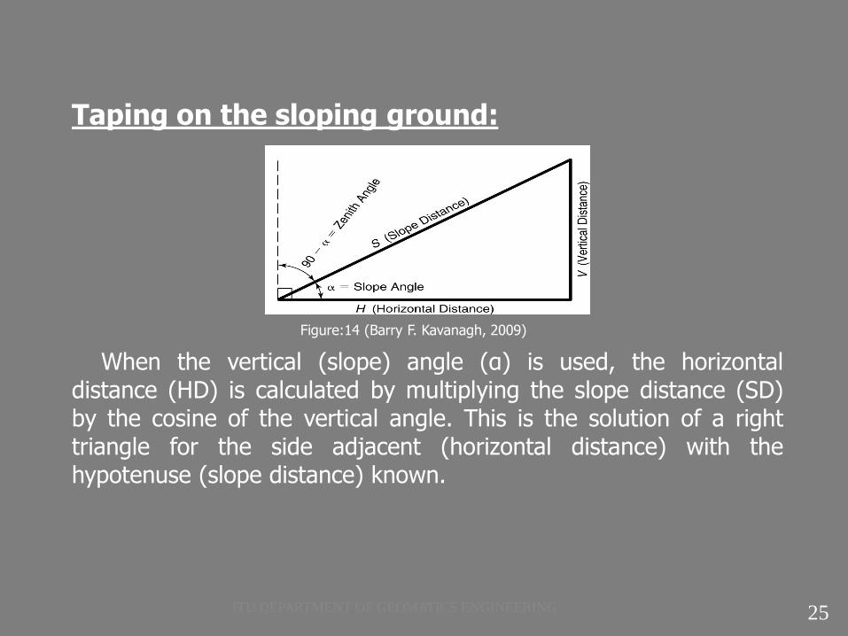
Figure:14 (Barry F. Kavanagh, 2009)
When the vertical (slope) angle (α) is used, the horizontal distance (HD) is calculated by multiplying the slope distance (SD) by the cosine of the vertical angle. This is the solution of a right triangle for the side adjacent (horizontal distance) with the hypotenuse (slope distance) known.
25 ITU DEPARTMENT OF GEOMATICS ENGINEERING

Taping on the sloping ground:
From basic trigonometry, we know that;
cosine = Adjacent Side / Hypotenuse Substituting the known values,
we have;
cos(α) = HD / SD Solving for HD by multiplying both sides of the equation by
SD, we get
If the zenith angle (z) is measured rather than the vertical angle, the calculations are nearly identical. The only variation is that the zenith angle is the complimentary angle of the vertical(slope)angle, so the sine function must be used. The formula is;
HD = SD.sin(z)
26
; HD = SD.cos(α)
ITU DEPARTMENT OF GEOMATICS ENGINEERING
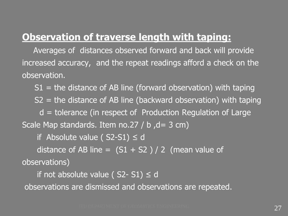
Observation of traverse length with taping:
Averages of distances observed forward and back will provide
increased accuracy, and the repeat readings afford a check on the
observation.
S1 = the distance of AB line (forward observation) with taping
S2 = the distance of AB line (backward observation) with taping
d = tolerance (in respect of Production Regulation of Large
Scale Map standards. Item no.27 / b ,d= 3 cm)
if Absolute value ( S2-S1) ≤ d
distance of AB line = (S1 + S2 ) / 2 (mean value of
observations)
if not absolute value ( S2- S1) ≤ d
observations are dismissed and observations are repeated.
27 ITU DEPARTMENT OF GEOMATICS ENGINEERING
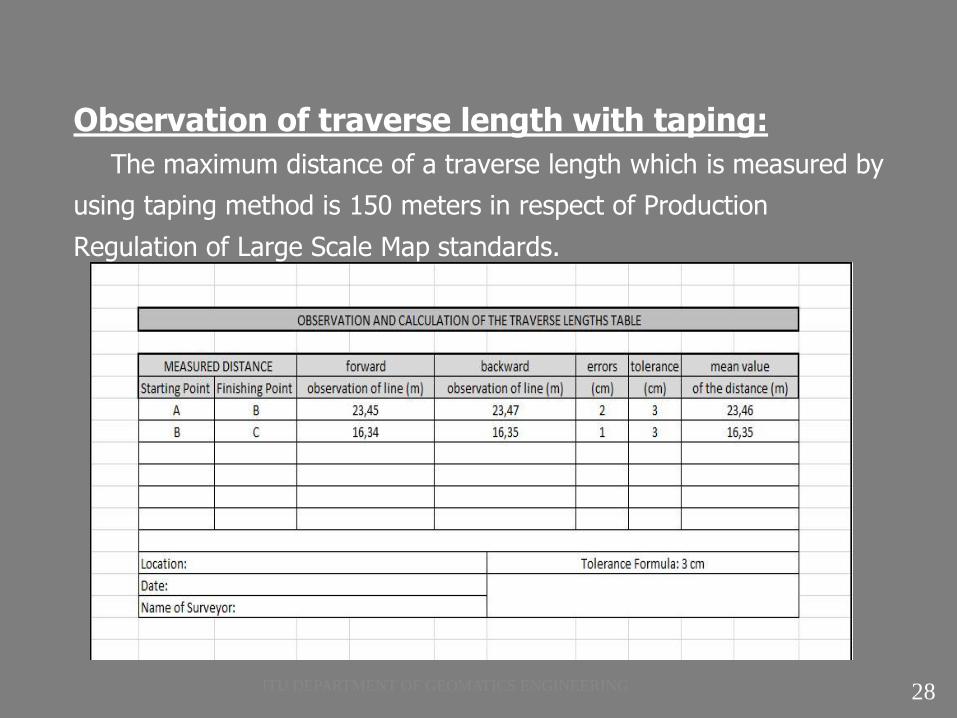
Observation of traverse length with taping:
The maximum distance of a traverse length which is measured by
using taping method is 150 meters in respect of Production
Regulation of Large Scale Map standards.
28 ITU DEPARTMENT OF GEOMATICS ENGINEERING

DISTANCE MEASUREMENT:
1)Sources of error in taping:
a) Instrumental errors : A tape may differ in actual length from its
nominal graduates length because of a defect in manufacture or
repair, or as a result of kinks.
b) Natural errors: The horizontal distance between end graduations
of tape varies because of the effects of temperature, wind, and
weight of tape itself.
c) Personal errors: Tapeperson setting pins, reading the tape, or
manipulating the equipment.
29 ITU DEPARTMENT OF GEOMATICS ENGINEERING

Sources of error in taping:
1.1.Proportional Errors:
When a tape is manufactured, it is intended to be a specific
length, plus or minus some tolerance. It may or may not actually
meet those specifications. When a field measurement is taken, the
acceptable error may be more or less than what the tape was
designed for. For high precision work, we need to measure several
known distances and determine if this tape is the proper length. If
not, we need next to determine if the error is in one or more
specific locations along the tape or if the error is proportional along
the length. If a known 50 m distance is measured to be 49.995 m
and a known 100 m distance to be 99.99 m, all measurements
made with that tape should be multiplied by a factor of 100/ 99.99
(known distance over measured distance). 30 ITU DEPARTMENT OF GEOMATICS ENGINEERING
Sources of error in taping:
1.2 .Temperature:
Whatever material is used to make a tape, that material will
expand and contract with any change in temperature. Some
materials are more affected than others, but every tape will change
length somewhat if warmed or cooled. If precise measurements are
needed, an adjustment needs to be made for the change in
temperature between the current temperature and the temperature
at the time the tape was checked against a known distance.
31 ITU DEPARTMENT OF GEOMATICS ENGINEERING

Sources of error in taping:
1.3. Sag:
When a tape is suspended from each end and not supported
along it's length, the weight of the chain causes it to sag and pull
the two ends toward each other. It is impossible to exert enough
outward force to fully overcome the sag. For all measurements,
adequate tension should be applied to minimize the effective
shortening of the tape.
Figure:15 (C.D. Ghilani, P.R. Wolf, 2008)
32 ITU DEPARTMENT OF GEOMATICS ENGINEERING
Sources of error in taping:
1.4. Tension ( inconsistent pull):
While a certain amount of tension is desirable to help offset the sag
effect, it will also stretch the tape. Steel will still stretch to some
degree if tension is applied. When a tape is checked against a
known distance, the applied tension should be controlled.
Subsequent precise measurements should be made using the same
tension, or if not, a correction should be applied.
33 ITU DEPARTMENT OF GEOMATICS ENGINEERING
Sources of error in taping:
1.5.Improper Plumbing:
Practice and steady nerves are necessary to hold a plumb bob still long enough to mark a point. The plumb will sway , even in calm weather. Errors caused by improper plumbing are random, since they may make distances either too long or to short. However, the errors would be systematic when taping directly against or in the direction of a strong wind.
It is difficult to hold the plumb bob steady over the point, applying appropriate tension while ensuring that the plumb bob string is precisely set at the correct tape graduation and reading tape graduation at the plumb bob string. To help steady plumb bob, it is held only a short distance above the mark and is repeatedly touched down. The plumb bob should not be allowed to rest on the point because this will result in an erroneous measurement.
34 ITU DEPARTMENT OF GEOMATICS ENGINEERING
Sources of error in taping:
1.6. Tape not horizontal and tape off-line:
Error caused by the tape not being horizontal are systematic and always make recorded lengths longer than true lengths. Also, errors from the tape being off – line are systematic and they too make recorded lengths longer than true lengths. This type of error can be eliminated by careful alignment.
1.7. Incorrect reading or interpolation (mistake):
The process of reading to hundredths on tapes graduated to
tenths, or to thousandths on tapes graduated to hundredths, is
called interpolation. Errors from this source are random over the
length of line. They can be reduced by care in reading, employing
a magnifying glass.
35 ITU DEPARTMENT OF GEOMATICS ENGINEERING
Sources of error in taping:
1.8. Constant errors:
If a tape has been kinked or broken and spliced back
together, there is a good chance that there will be a consistent
error for any distances measured using that portion of the tape.
This error needs to be added or subtracted as appropriate each
time.
36 ITU DEPARTMENT OF GEOMATICS ENGINEERING

Electronic Distance Measurement:
A major advance in surveying instrumentation occurred approximately 60 years ago with the development of electronic distance measuring (EDM) instruments.
37 ITU DEPARTMENT OF GEOMATICS ENGINEERING
Electronic Distance Measurement:
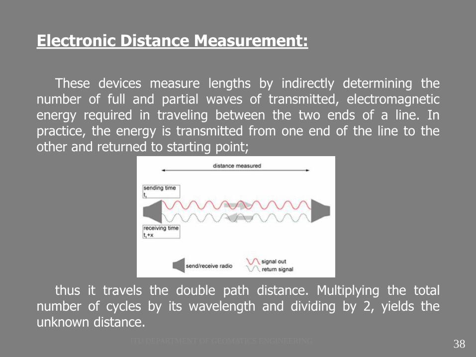
These devices measure lengths by indirectly determining the number of full and partial waves of transmitted, electromagnetic energy required in traveling between the two ends of a line. In practice, the energy is transmitted from one end of the line to the other and returned to starting point;
thus it travels the double path distance. Multiplying the total number of cycles by its wavelength and dividing by 2, yields the unknown distance.
38 ITU DEPARTMENT OF GEOMATICS ENGINEERING
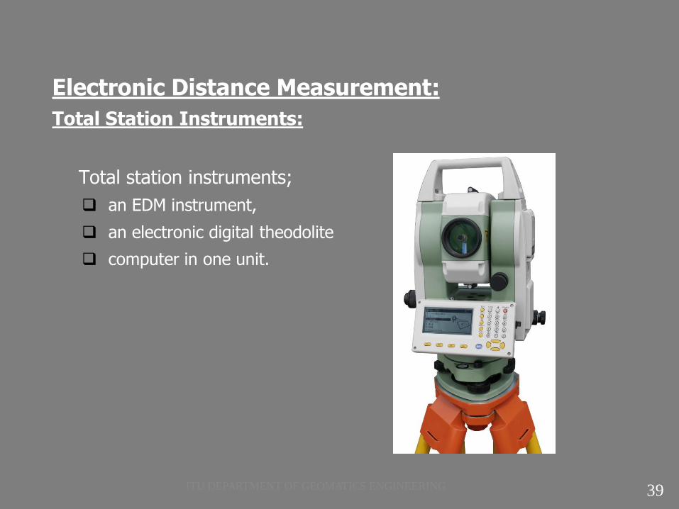
Electronic Distance Measurement:
Total Station Instruments:
Total station instruments;
an EDM instrument,
an electronic digital theodolite
computer in one unit.
39 ITU DEPARTMENT OF GEOMATICS ENGINEERING
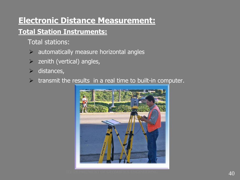
Electronic Distance Measurement:
Total Station Instruments:
Total stations:
automatically measure horizontal angles
zenith (vertical) angles,
distances,
transmit the results in a real time to built-in computer.
40 ITU DEPARTMENT OF GEOMATICS ENGINEERING

Electronic Distance Measurement:
Total Station Instruments:
The horizontal and zenith (or altitude) angle and slope distance can be displayed, and then upon keyboard commands, horizontal and vertical distance components can be computed from these data and displayed. If the instrument is oriented in direction and the coordinates of the occupied station are input in the system, the coordinates of any point sighted can be immediately obtained. These data can all be stored within the instrument, or in a data collector.
41 ITU DEPARTMENT OF GEOMATICS ENGINEERING
Electronic Distance Measurement:
All EDM equipments measures the slope distance between two stations.
If The EDM unit is incorporated into a total station instrument, then it can reduce the distances to their horizontal components automatically.
With some of the earliest EDM’s, this could not be done, and reductions were carried out manually.
It is presumed, of course, that slope distances are first corrected for instrumental and atmospheric conditions.
42 ITU DEPARTMENT OF GEOMATICS ENGINEERING

Electronic Distance Measurement:
Reduction of slope distance to horizontal can be based on elevation differences, or on zenith (or vertical) angle. Because of the Earth curvature, long lines must be treated differently in reduction than short ones.
43 ITU DEPARTMENT OF GEOMATICS ENGINEERING

Electronic Distance Measurement:
Total Station Prism - Reflector
Figure:16 (C.D. Ghilani, P.R. Wolf, 2008)
44 ITU DEPARTMENT OF GEOMATICS ENGINEERING

REFERENCES:
• Basic Surveying -The Theory and Practice, Oregon Department of Transportation,
Geometronics Unit, Ninth Annual Seminar, February 2000.
• C.D. Ghilani, P.R. Wolf; Elementary Surveying , Pearson Education International Edition,
Twelfth Edition,2008 .
• Barry F. Kavanagh, Surveying Principles and Applications, Pearson Education International
Edition, Eight Edition,2009.
• Ü.Öğün , Topografya Ders Notları ,
• E.Tarı , M.Sahin , Surveying II Lecture Notes - Slides ,
• U.Özerman , Topografya Ders Notları , Spring 2010
• Production Regulation of Large Scale Map , 2005
• H.Özener , Surveying Lecture Notes , CE200 Surveying, Boğaziçi University Kandilli
Observatory and Earthquake Research Institute Department of Geodesy
45 ITU DEPARTMENT OF GEOMATICS ENGINEERING


