54
Ekaterina Aleksandrova IT INFRASTRUCTURE DEVELOPMENT Case Petrocast Silica Bachelor’s Thesis Information Technology December 2016

Ekaterina Aleksandrova
IT INFRASTRUCTURE DEVELOPMENT Case Petrocast Silica
Bachelor’s Thesis
Information Technology
December 2016

DESCRIPTION Date of the bachelor's thesis
02.12.2016
Author(s)
Ekaterina Aleksandrova
Degree programme and option
Information Technology
Name of the bachelor's thesis
IT infrastructure development, case Petrocast Silica
Abstract
The scope of this study was to investigate a network topology and devices` configurations in a living environment of a small business. Other aim of this thesis was to look for potential or existing prob-lems with security, connectivity or overall usability of the network and suggest a list of improve-ments, changes and technologies that may help to resolve the troubles that the company was facing.
The study was carried out with the help of various tools, manuals and software like PacketTracer and network handbooks to gather intelligence about the existing problems of the enterprise and the trou-bles that might happen in the nearest future and damage the network or the data stored on the local devices.
The results revealed a scope of certain issues like a topological vulnerability of the network, poor network devices` configurations and violations of basic security and safety rules on the workplace.
The study suggests changing the network topology, adding new configurations like DHCP, VLANs, ACL, PAT etc. The study also provides the readers with a set of security measures that can be imple-mented to both network and human environments of the enterprise.
Subject headings, (keywords)
Network design, infrastructure development, IT, routing, security
Pages Language URN
49 English
Remarks, notes on appendices
Tutor
Matti Juutilainen
Employer of the bachelor's thesis
Petrocast Silica

LIST OF ABBREVIATIONS
ACL Access Control List
BDR Backup Designated Router
BPDU Bridge Protocol Data Unit
CPU Central Processing Unit
DDOS Distributed Denial of Service
DHCP Dynamic Host Configuration Protocol
DOS Denial of Service
DR Designated Router
ECC Error-Correcting Code
EIGRP Enhanced Interior Gateway Routing Protocol
HDD Hard Disk Drive
IDS Intrusion Detection System
IP Internet Protocol
IPS Intrusion Prevention System
ISP Internet Service Provider
LAN Local Area Network
NAT Network Address Translation
OS Operating System
OSPF Open Shortest Path First
PAT Port Address Translation
RAID Redundancy Array of Independent Disks

RAM Random Access Memory
RIP Routing Information Protocol
STP Shielded Twisted Pair
STP Spanning Tree Protocol
TCP Transmission Control Protocol
UDP User Datagram Protocol
UTP Unshielded Twisted Pair
VLAN Virtual Local Area Network

CONTENTS
LIST OF ABBREVIATIONS ........................................................................................ 1
1 INTRODUCTION................................................................................................ 1
2 SMALL BUSINESS IT INFRASTRUCTURE ................................................... 2
2.1 Network configurations .............................................................................. 2
2.1.1 Cabling .......................................................................................... 2
2.1.2 Network topology .......................................................................... 4
2.1.3 Routing protocols .......................................................................... 6
2.1.4 VLANs ........................................................................................ 10
2.1.5 NAT/PAT .................................................................................... 12
2.1.6 DHCP .......................................................................................... 13
2.1.7 Device selection........................................................................... 14
2.2 End Devices .............................................................................................. 14
2.2.1 PC configurations ........................................................................ 15
2.2.2 Server configurations................................................................... 15
2.3 Security configurations ............................................................................. 17
3 PRACTICAL PART .......................................................................................... 20
3.1 Resources of the company ........................................................................ 20
3.1.1 End devices .................................................................................. 20
3.1.2 Network map ............................................................................... 22
3.2 Network configurations ............................................................................ 23
3.3 End devices ............................................................................................... 34
3.3.1 PC configurations ........................................................................ 34
3.3.2 Server configurations................................................................... 36
3.4 Security configurations ............................................................................. 40
3.4.1 Physical network security ............................................................ 40
3.4.2 Software-based network security ................................................ 42
3.4.3 Physical security of end devices .................................................. 43
3.4.4 Software-based security of end devices ...................................... 43
4 CONCLUSIONS ................................................................................................ 44
BIBLIOGRAPHY ........................................................................................................ 47

1
1 INTRODUCTION
Nowadays more and more companies of different size and purpose are concentrating
on their IT infrastructure and resources to improve their quality of service and to ex-
pand their field of work. This does not only apply to those who provide services in the
area of, for example, data center management or networking – many firms are con-
cerned about how they manage internal document flow, data security and energy effi-
ciency.
One of the companies in Russia called “Petrocast silica” works with concrete and re-
fractory materials and until now was not concerned about their IT infrastructure. After
some severe problems and document losses, I was asked to improve the security –
both internal and external – and implement several technologies to prevent these un-
fortunate mistakes in the future. I was also given necessary permissions to revise the
documents concerning network and security configurations of the company.
To find the origins of these problems and solve them, I intend to revise the hardware
and software that the company uses, correct the implementation mistakes if there are
any and deploy new software and hardware to replace outdated and malfunctioned
ones. I plan to spend around four months on this problem using different resources
like manuals, study books, existing network plans and ISP documents, Packet Tracer
etc. The aim of my study is to present a working prototype of small company’s net-
work with all necessary configurations including network, security and end devices’
configurations.
My study consists of four chapters. In Chapter 2, I am going to list and explain the
most common principles, methods and practices that are used in the modern IT envi-
ronment. In Chapter 3, I intend to revise the IT environment of Petrocast Silica and
make changes, if necessary. I am also going to make a network prototype using Packet
Tracer software as well as other available equipment. Finally, in the last chapter I state
the original problem and the way it was solved.
2
2 SMALL BUSINESS IT INFRASTRUCTURE
This chapter of my thesis introduces the technologies and principles that are usually
implemented and used in small business IT infrastructure. I have decided to divide this
chapter into three parts: the first part is about network configuration, routing proto-
cols, cabling etc., the second part is about end devices' configurations – both hard-
ware and software, the third part is all about hardware and software security of the
network and end devices like PCs.
2.1 Network configurations
In this section I explain the main principles and techniques that are used in a small
business network environment. These include, for example, cable types, network to-
pology types, routing protocols etc.
2.1.1 Cabling
There are several options to choose the cabling from. First, a Twisted Pair Cable is
usually used inside buildings, offices and homes. Twisted Pair Cable has two options
– STP and UTP.
UTP cable is known to be the most popular cabling solution: it is relatively cheap, it is
easy to install and its capabilities are being improved constantly. Usually, a UTP cable
consists of several pairs of twisted wires that are covered by non-conducting material.
The most commonly used cable has four twisted pairs inside. Each wire in a pair is
covered by an insulation material (Barnett, Groth and McBee 2004). Currently, there
are seven types of UTP cables. These types and their characteristics are listed in Table
1.

3
Table 1. UTP cable categories
UTP Category Data Rate Maximum
Length
Typical Application
CAT1 Up to 1Mbps - Old Telephone Cable
CAT2 Up to 4Mbps - Token Ring Networks
CAT3 Up to 10Mbps 100m Token Ring and 10BASE-T Ethernet
CAT4 Up to 16Mbps 100m Token Ring Network
CAT5 Up to
100Mbps
100m Ethernet, FastEthernet, Token Ring
CAT5e Up to 1Gbps 100m Ethernet, FastEthernet, Gigabit Ether-
net
CAT6 Up to 10Gbps 100m Gigabit Ethernet, 10G Ethernet (55m)
CAT6a Up to 10Gbps 100m Gigabit Ethernet, 10G Ethernet (55m)
CAT7 Up to 10Gbps 100m Gigabit Ethernet, 10G Ethernet (100m)
STP cable is usually more expensive and more difficult to implement, though it has
some advantages. The main difference from the Unshielded Twisted Pair Cable is that
in STP there is a thin layer of conducting shield placed around the twisted wires, or
each pair of wires is shielded with foil separately. This shield preserves the wires and
the data that the wires carry from the electromagnetic interference that appears in
large workspaces with heavy machinery and/or other massive electrical equipment
(Barnett, Groth and McBee 2004).
The other option that is widely used nowadays is Fiber Optic Cable. This cable uses a
glass or plastic core to transmit data with the use of light – naturally, fiber optic cable
is not electrical. However, it uses light-emitting diodes to transmit light through the
core. Usually, plastic-core fiber optic cable is cheaper and easier to implement than
glass-core fiber optic cable, but the maximum distance for the data is less than when
using glass.
Fiber optic cable consists of the outer jacket, the dielectric material, protective buffer,
low-refracting cladding and the fiber core itself – glass or plastic. Two types of fiber
optic cables are used in modern networks – single-mode and multimode cables. The
light in the single-mode cable goes straight through the core to its destination and does
not touch the cladding. In multimode fiber optic cable there are multiple beams of
light bouncing off the cladding. In order not to mix up different sequences of data, the
core and the cladding have a distinctive refractive index difference between them.
Alternatively, in case the graded index principle is used, the core of the cable consists

4
of several layers of conducting material. Each layer has the refraction index lower
than that of the next layer, going from the center of the core to the cladding.
The main difference between the fiber optic cable and twisted pair cable is, of course,
the data transmission distance – while twisted pair cable can provide the clients with
no more than 100 meters from one point to another, with fiber optic cable it is possible
to have kilometers of distance between the sending point and the destination. There
are other distinguishable differences: the bandwidth of the fiber optic cable is poten-
tially higher than that of the copper cables. In addition to that, fiber optic cable does
not generate nor is susceptible to electromagnetic interference and crosstalk. The
drawback of the fiber optic cabling is its cost and the difficulty of implementation, and
not all the equipment supports this kind of cabling.
2.1.2 Network topology
In this part of the chapter, I introduce the most common topologies for the small com-
panies` networks and explain their advantages and drawbacks. There are several kinds
of network topologies that are popular in the small companies` networks. I am going
to focus on five most common ones.
It is important to remember that there are generally two types of topologies – physical
topology and logical topology. Physical topology of the networks takes care of the
way how the network devices are cabled and connected to the main network. Howev-
er, logical topology refers to the way how data travels between the devices in the net-
work – regardless of the physical connections.
One of them is bus topology where the devices are connected with a single network
cable. This topology is considered the simplest and the cheapest one, because it is ra-
ther easy to implement and the least amount of cable is consumed by the network, but
the problems come when two or more of the hosts send packets on the same bus at the
same time. This problem is avoided in the star topology where each host has its own
dedicated cable that runs to the hub or the switch – this way the communication be-
tween the devices is not interrupted. In addition to that, the network that uses star to-
pology scales easily. However, this topology is expensive to implement as each of the
hosts requite its cable. The other topology that is worth mentioning is ring topology:
5
each host connects to two other hosts, so that the ring is formed from the hosts and the
network cables. It is relatively easy to extend, but this process requires disconnecting
the hosts from the network and disrupts the network. The next topology is mesh to-
pology where each device has as many private connections as there are devices left in
the network. This approach makes the network fault diagnosis easier when comparing
to the other previously listed topologies, but keeping in mind the total number of con-
nections in the network, it is fair to say that this is also one of the most expensive to-
pologies in the sense of time and money spent to connect all the hosts. Tree topology
or hierarchical topology has only one host between any two on the network. With this
topology, it is easy to expand the network and add new hosts and connections but the
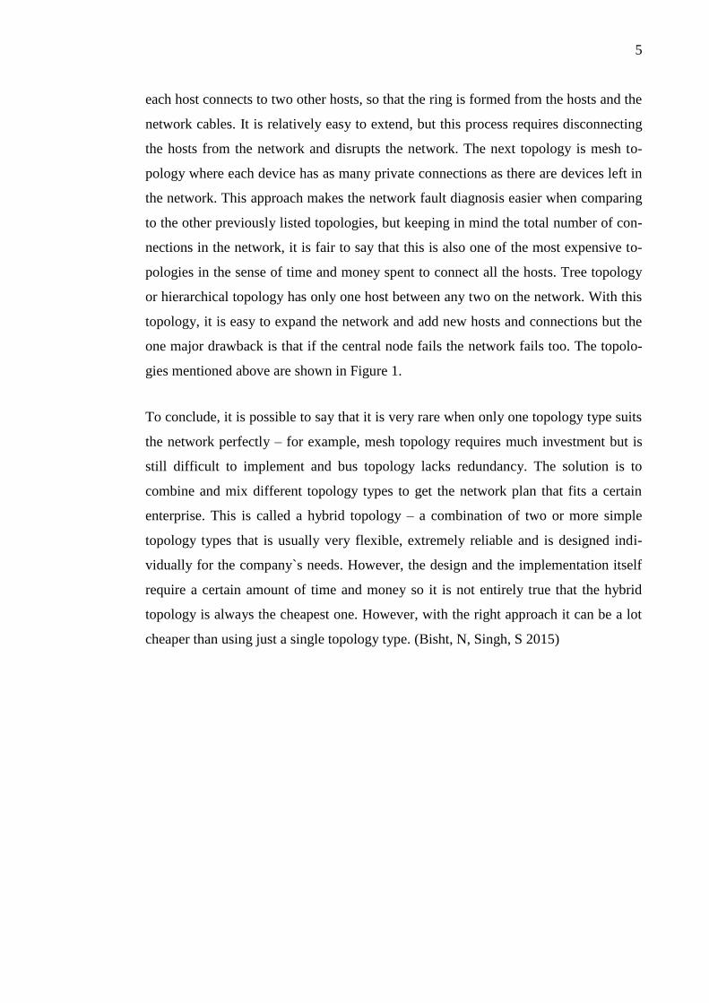
one major drawback is that if the central node fails the network fails too. The topolo-
gies mentioned above are shown in Figure 1.
To conclude, it is possible to say that it is very rare when only one topology type suits
the network perfectly – for example, mesh topology requires much investment but is
still difficult to implement and bus topology lacks redundancy. The solution is to
combine and mix different topology types to get the network plan that fits a certain
enterprise. This is called a hybrid topology – a combination of two or more simple
topology types that is usually very flexible, extremely reliable and is designed indi-
vidually for the company`s needs. However, the design and the implementation itself
require a certain amount of time and money so it is not entirely true that the hybrid
topology is always the cheapest one. However, with the right approach it can be a lot
cheaper than using just a single topology type. (Bisht, N, Singh, S 2015)

6
Figure 1. Network Topology
2.1.3 Routing protocols
In this part of my thesis, I focus on the routing protocol’s definition and the protocols
that are widely used nowadays in different kinds of environments. First, it is important
to understand what a routing protocol is. Routing is a process of finding a way from
the starting point to the destination – like a path from home to school. Routing con-
sists of finding all the possible paths and choosing the shortest (or the least time-
consuming) path. It is also used for choosing the other path if the shortest one is
closed. Therefore, a routing protocol does these things for the data that is flowing be-
tween the hosts. A routing protocol makes a routing table for the hosts in the network.
As the title suggests, there is a number of different routing protocols for different oc-
casions.
The Border Gateway Protocol or BGP routes data between or within autonomous sys-
tems. A system is considered autonomous if it is a network or a number of networks
that follow the same set of rules and routing policies. Usually this protocol is used to
exchange data between ISPs. If two or more ISPs exchange data using this protocol, it
is then called an external BGP. Similarly, if the ISP is using this protocol within an
autonomous system, it is called an internal BGP. When two neighboring networks
using BGP are establishing the connection, full routing information gathered by BGP
is exchanged. Then, the table is updated only when the routing table changes are de-
tected. However, BGP does not send periodic routing table updates. To sum up, the

7
protocol is extremely scalable and stable – that is achieved by using many route at-
tributes that define different routing policies. Basically, this is the protocol that the
Internet uses. Normally, the Local Area Network of a company is built using an Inte-
rior Gateway Protocol rather than Border Gateway Protocol.
RIP stands for Routing Information Protocol. This is probably one of the oldest rout-
ing protocols and one of the easiest to implement. It utilizes User Datagram Protocol
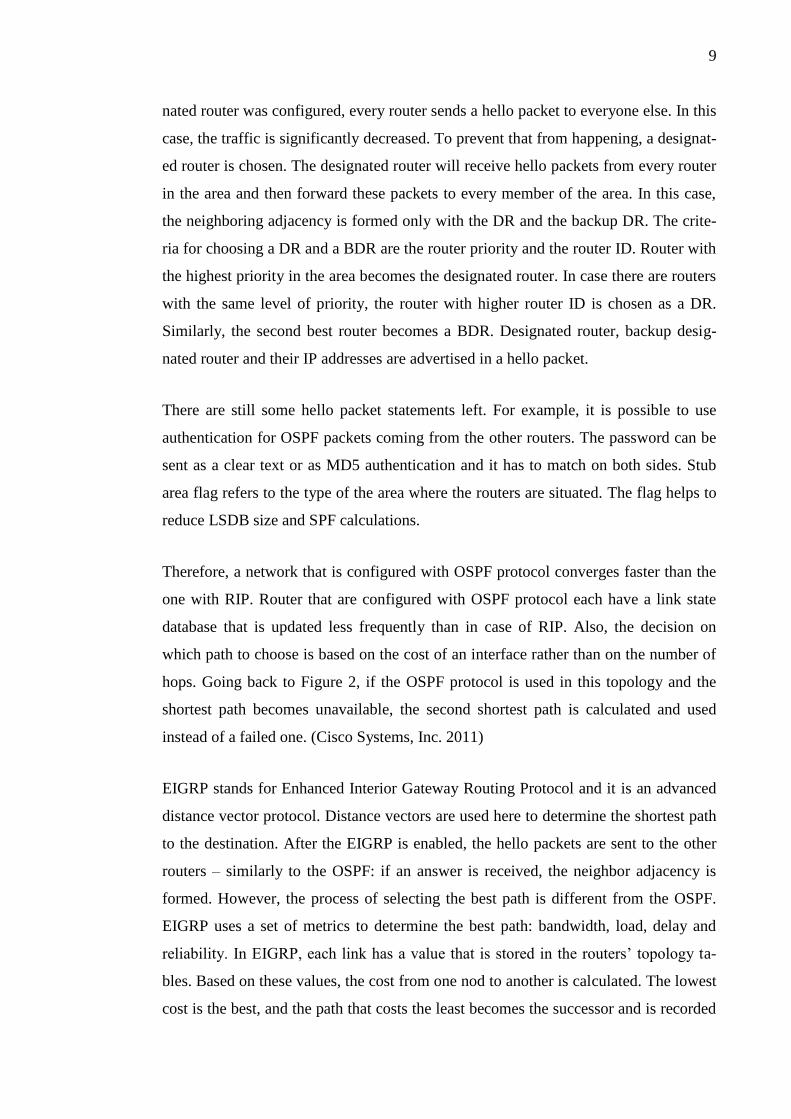
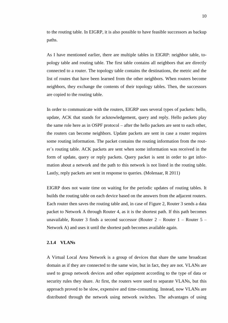
packets when exchanging the routing information. Let us take a look at Figure 2 with
an example of a simple network. A Routing Information Protocol is implemented
there, so every 30 seconds each router sends an update to the adjacent routers in order
to keep the routing table updated. If a Router 3 is to send a packet to the Network A, it
is first to count the number of hops to its destination. To the right side of the Router 3,
it is required two hops to reach the Network A. To the left side, however, it is required
three hops to the destination. The RIP chooses the right path and sends a packet, when
at the same time it discards the information about number of hops that it has learned
from Router 2. However, in case the shortest path through Router 4 fails, it requires
some time to discard the inactive route and refresh the routing table. Usually it takes
three update periods, 30 seconds each. After that, Router 2 re-advertises the route to
the Network A – that is the destination for the packet coming from Router 3. This also
takes up to 30 seconds. In conclusion, it takes approximately two minutes for a RIP to
deal with a failure in the network.
Figure 2. Example of a simple network
OSPF stands for Open Shortest Path First. It is an interior gateway routing protocol
that uses link states instead of distance vectors. The process of filling the routing table

8
is divided into several steps. First, a router generates a link-state advertisement that is
a set of all the link-states on this router. After this, all routers exchange their sets of
link-states. If the link-state collection that is received by a router is different from the
one it has, the router stores this version of the link-state set and sends the updated ver-
sion to the other routers. Once everyone has the updated version, the link-state data-
base is complete and the shortest path tree is calculated using Dijkstra algorithm.
One of the main OSPF concepts is the concept of areas. Area is a group of routers or
individual interfaces on a router. By default, there is always an Area 0 or a Backbone
area. No matter how many areas there are in the network, they all must be connected
to the Backbone area in order to communicate with each other. In other words, a
packet that is sent from a hypothetical Area 13 to a hypothetical Area 76 must go
through Area 0. Areas are used to speed up the process of building the routing table —
a router that belongs to an area stores the routing table only within the said area. To
share the data about the network it is first necessary for the routers to become neigh-
bors. For that they send hello packets to each other. A hello packet consists of several
points that are extremely important: router ID, hello/dead interval, neighbors, area ID,
router priority, DR and BDR IP address, authentication password and stub area flag.
Router ID is the highest IP address of the router on any of the active interfaces. It is
also possible and preferable for a router to have a loopback IP address as a router ID.
The reason is that the loopback interface is not likely to go down unless the router
itself crashes. Hello/dead interval is a period of time when the neighbor relationship is
valid. When the time is up, a new hello packet is sent and the neighbor adjacency is
formed. If there was no reply from the former neighbor, the neighbor is marked as
dead. Speaking about OSPF, a neighbor is a router that has answered a hello packet,
and the necessary values in the packet are set correctly and similarly. The amount of
neighbors and data about them are also shared in the hello packet. Area ID is the
number of the area where the routers are located, it has to be the same on both sides in
order to form the adjacency. Router priority is a number that determines a designated
and backup designated router. (Juniper Networks, Inc. 2016)
A designated router is used in order to prevent the bandwidth of the network from
flooding with the hello packets and routing table updates. In an area where no desig-
9
nated router was configured, every router sends a hello packet to everyone else. In this
case, the traffic is significantly decreased. To prevent that from happening, a designat-
ed router is chosen. The designated router will receive hello packets from every router
in the area and then forward these packets to every member of the area. In this case,
the neighboring adjacency is formed only with the DR and the backup DR. The crite-
ria for choosing a DR and a BDR are the router priority and the router ID. Router with
the highest priority in the area becomes the designated router. In case there are routers
with the same level of priority, the router with higher router ID is chosen as a DR.
Similarly, the second best router becomes a BDR. Designated router, backup desig-
nated router and their IP addresses are advertised in a hello packet.
There are still some hello packet statements left. For example, it is possible to use
authentication for OSPF packets coming from the other routers. The password can be
sent as a clear text or as MD5 authentication and it has to match on both sides. Stub
area flag refers to the type of the area where the routers are situated. The flag helps to
reduce LSDB size and SPF calculations.
Therefore, a network that is configured with OSPF protocol converges faster than the
one with RIP. Router that are configured with OSPF protocol each have a link state
database that is updated less frequently than in case of RIP. Also, the decision on
which path to choose is based on the cost of an interface rather than on the number of
hops. Going back to Figure 2, if the OSPF protocol is used in this topology and the
shortest path becomes unavailable, the second shortest path is calculated and used
instead of a failed one. (Cisco Systems, Inc. 2011)
EIGRP stands for Enhanced Interior Gateway Routing Protocol and it is an advanced
distance vector protocol. Distance vectors are used here to determine the shortest path
to the destination. After the EIGRP is enabled, the hello packets are sent to the other
routers – similarly to the OSPF: if an answer is received, the neighbor adjacency is
formed. However, the process of selecting the best path is different from the OSPF.
EIGRP uses a set of metrics to determine the best path: bandwidth, load, delay and
reliability. In EIGRP, each link has a value that is stored in the routers’ topology ta-
bles. Based on these values, the cost from one nod to another is calculated. The lowest
cost is the best, and the path that costs the least becomes the successor and is recorded
10
to the routing table. In EIGRP, it is also possible to have feasible successors as backup
paths.
As I have mentioned earlier, there are multiple tables in EIGRP: neighbor table, to-
pology table and routing table. The first table contains all neighbors that are directly
connected to a router. The topology table contains the destinations, the metric and the
list of routes that have been learned from the other neighbors. When routers become
neighbors, they exchange the contents of their topology tables. Then, the successors
are copied to the routing table.
In order to communicate with the routers, EIGRP uses several types of packets: hello,
update, ACK that stands for acknowledgement, query and reply. Hello packets play
the same role here as in OSPF protocol – after the hello packets are sent to each other,
the routers can become neighbors. Update packets are sent in case a router requires
some routing information. The packet contains the routing information from the rout-
er`s routing table. ACK packets are sent when some information was received in the
form of update, query or reply packets. Query packet is sent in order to get infor-
mation about a network and the path to this network is not listed in the routing table.
Lastly, reply packets are sent in response to queries. (Molenaar, R 2011)
EIGRP does not waste time on waiting for the periodic updates of routing tables. It
builds the routing table on each device based on the answers from the adjacent routers.
Each router then saves the routing table and, in case of Figure 2, Router 3 sends a data
packet to Network A through Router 4, as it is the shortest path. If this path becomes
unavailable, Router 3 finds a second successor (Router 2 – Router 1 – Router 5 –
Network A) and uses it until the shortest path becomes available again.
2.1.4 VLANs
A Virtual Local Area Network is a group of devices that share the same broadcast
domain as if they are connected to the same wire, but in fact, they are not. VLANs are
used to group network devices and other equipment according to the type of data or
security rules they share. At first, the routers were used to separate VLANs, but this
approach proved to be slow, expensive and time-consuming. Instead, now VLANs are
distributed through the network using network switches. The advantages of using

11
switch VLANs over using routers are numerous. One of the most important features is
performance: while switches are fast to forward data, routers have created bottlenecks
in the networks, slowing down the process. The other benefit is how easily the virtual
groups are formed and how fast the data is forwarded between the members of the
same group. In addition, with VLANs it is easy to apply various security rules and
access policies to the users, if they are in the same virtual group. Great flexibility of
this approach allows users to move freely, and while plugged in on the new location,
be in the same VLAN with the same rules and privileges. (Farrel, M 2009)
The most common way to implement VLANs is to select a group of ports on the
switch and assign a set of rules to the PCs or similar devices that are connected to
these ports. This approach is called port-based VLANs. When the device is connected
to a port that belongs to a certain VLAN, this device automatically becomes a member
of this VLAN. In case there is more than one switch in the network, it might be neces-
sary for the user of one VLAN to communicate with the other VLAN. For that, trunk
ports are configured. A trunk port is a port on the switch that is occupied with VLAN
traffic with the help of trunking protocols. The most common trunk protocol is IEEE
802.1Q. A 802.1Q frame carries a VLAN identifier that helps to figure out to which
Virtual LAN the traffic belongs.
Trunk port operates in trunk mode – one of the several switchport modes available
when configuring VLANs. The other modes are access mode, dynamic auto mode and
dynamic desirable mode. A port configured with access mode carries the traffic that
belongs only to the VLAN that the port was assigned to. As I have said earlier, a trunk
port carries traffic for multiple VLANs. A port configured with dynamic auto mode
stays in access mode unless it is asked to become a trunk. A port in dynamic desirable
mode becomes a trunk if the port on the other side agrees to be a trunk too. Usually
only trunk mode and access mode are used. (Molenaar, R 2011)
It is not only possible to assign different ports to different VLANs on one switch – it
is also possible to assign different ports on different switches to the same VLAN. It is
useful when the devices are connected to the different switches but they still belong to
the same VLAN and follow the same rules. For example, there is a Research and De-
velopment department in the company, and people who work there are spread between

12
two floors of the building. Assuming that there is a separate switch for each floor and
there are other people from other departments, there is a need to unite Research and
Development workers’ workstations in the same VLAN. The solution for that is frame
tagging. Nowadays, this is the most popular approach for such situations. Four bytes
are put in the Ethernet packet header – two bytes are Tag Protocol Identifier that is
used as a notification that a certain data (in this case, VLAN data) is following, and
another two bytes are Tag Control Information itself. In TCI, three bytes are given to
the User Priority levels – zero is the lowest priority level and seven is the highest pri-
ority level. Canonical Format Indicator or CFI is given one bit: this indicator is used to
ensure the compatibility between Ethernet network and Token Ring network. Finally,
the last twelve bits are given to the VLAN ID – the most important thing here: VLAN
ID tells the switch to which VLAN it is to forward the packet. Therefore, if the tag-
ging is implemented, a tagged packet from one switch goes to another one, and then
the second switch searches for the same VLAN ID as in the packet header. (Allied
Telesis 2015)
However, it is possible that the packet can come untagged. It means that the port
where it came from is untagged too – it belongs to a native VLAN. Clearly, there can
be only one native VLAN in the network, or the switches will not figure out to which
VLAN they are to forward untagged packets. In addition, it is a good practice not to
configure native VLAN on the port that is connected to the other port on the other
switch – this way the switches will not accept any untagged packets on this port.
2.1.5 NAT/PAT
As long as there is just one public IP address given to the company, it is necessary to
implement either Network Address Translation (NAT) or Port Address Translation
(PAT). Network Address Translation is a technology that allows a certain network
device like a firewall or a router to represent other device in a private LAN when act-
ing in a public network. With NAT it is possible to use one public IP address even if
on the LAN there are more than one device. This technique maps the IP address in one
network (in our case, LAN) to the IP address on the other network (public IP address
in the Internet). (Nokia 2003)

13
There are two types of Network Address Translation types. First type is static NAT,
the simplest of all the types. Static NAT uses one-to-one IP address translation. In
other words, there is one specific IP address in the Local Area Network that is mapped
to a specific IP address in the Internet. The second, dynamic NAT allows to configure
static NAT entries automatically, on-the-go by creating a pool of addresses on the
inside LAN and a similar pool on the outside LAN. This way, one-to-one mappings
are created automatically and, therefore, a lot of time is saved in case there are numer-
ous entries in the address pools.
A more advanced tool is NAT overload or Port Address Translation. This tool allows
multiple users on the inside LAN utilize a single IP address on the outside network.
For that, NAT overload uses not only the inside IP addresses but also port numbers to
distinguish one user from another. Each host on the inside LAN is assigned with a port
number that acts as a source port and a destination port. (Cisco Systems, Inc. 2004)
2.1.6 DHCP
Dynamic Host Configuration Protocol is a method developed from the Bootstrap Pro-
tocol and used to pass the necessary configurations through TCP/IP network. DHCP is
able to assign IP addresses and other network configurations to hosts automatically.
DHCP works on a client/server basis where a server delivers pre-allocated network
addresses to its clients.
DHCP can operate in different ways. First, a network administrator provides the
DHCP server with an appropriate IP address manually, and the server then forwards
the address to a host. Second, a DCHP-configured server can assign a permanent net-
work address to a host on the network. Last way is dynamic allocation: a DHCP server
provides a host with an IP address for a limited time that is called lease. It is also pos-
sible to create a pool of appropriate IP addresses and assign dynamic network ad-
dresses to the hosts. (Cisco Systems Inc. 2012)
An administrator is to create a pool of available IP addresses first, and then the IP ad-
dress is assigned to the client for a certain time. After this time is up, the server as-
signs the IP address again – not necessarily the same as it was before. Lease time can
be extended by the client as well as by the administrator dynamically. The advantage
14
of this method is that there is no need to assign the IP address manually to each host in
the network. On the other hand, the software keeps track of free IP addresses and as-
signs one to the host that goes to the local network. (Droms, R, Lemon, T 2003)
The process of assigning an IP address is relatively simple. First, the client sends a
broadcast DISCOVER packet on the network, letting the DCHP server know that
there is a host that requires network configuration. After that, the DCHP server sends
the OFFER packet with the necessary lease information. When the client acknowledg-
es the OFFER packet, it sends the REQUEST packet to the server that answers with
an ACK packet. The network information is obtained and the client workstation is
now a member of the network. (Cisco Systems Inc. 2002)
2.1.7 Device selection
Although the routing protocols and the cabling are important, the right network device
can make it easier for the client to use the network and to maintain in in working state.
It is quite common that in small business networks people are trying to save money on
almost everything if possible. However, with this approach they sometimes end up
with the devices that do not answer the speed or security requirements.
Usually, the price for the device rises the more feature the device has. Although not
every company is ready to spend hundreds or even thousands of euros for the network
devices, it does not mean that the only devices left are those that work better in home
environment. On the other hand, it is possible to buy a router or a switch with a num-
ber of features like console connection, PortFast, DHCP for a decent price.
2.2 End Devices
In this part of my research, I am going to talk about PC configurations and server im-
plementation in modern IT infrastructure. I am also going to list several security
threats and ways to prevent the attacks to happen.
15
2.2.1 PC configurations
It is obvious that the bigger the company is the more differences there are among the
workstations for the employees. However, a common practice is to remove as many
differences as possible to make it easier for users – to work on different workstations
and for the administrators – to maintain and troubleshoot the PCs. For example, a
good solution is to reduce the amount of different versions of the operating systems
installed on the computers – this way the network administrator spends significantly
less time tuning the PCs, applying the necessary settings and installing the updates.
The same applies to the software and the drivers – the PCs might not support the latest
version or the users do not need it for their work. Nevertheless, when most of the
company’s workstations (or, at least, a certain group) uses the same software, moving
between PCs or troubleshooting will not be an issue neither for the users nor for the
administrators.
The drivers, however, bring us to the hardware configurations. It is important to real-
ize that the hardware may not require frequent upgrades, but it does not mean that it
does not require upgrades at all. While the new companies buy modern or close-to-
modern PCs, the older companies are often not ready to part with the money and up-
grade the workstations that they already have. Still, at some point the software that the
company uses will be updated and require more power from the CPU or more memory
from the hard drives. Alternatively, one of the components in the workstation might
fail and corrupt the important data. Therefore, hardware upgrades are inevitable and
sometimes crucial for the safety of the data and the pace of the company’s work.
2.2.2 Server configurations
Depending on the size of the enterprise, the company might decide to implement a
server in their network environment. To talk about the server configurations, it is nec-
essary to understand what the server is and why the company needs it.
A server is a device or a program that provides services to the clients – the work-
stations in the network. Its purpose is to store network data and provide shared ser-
vices like internet access, other network access, shared printers and other equipment.
A server is usually capable of doing several different tasks simultaneously. However,

16
there are servers that run only specific type of tasks like file servers, database servers
etc. These servers are dedicated.
There are certain differences between a server and a PC – both hardware and software.
Although the overall hardware configurations are almost the same, some components
are more powerful than in PCs and some components are not. The CPU of the server
usually consists of multiple cores and a large cache. The purpose of the CPU cache is
to store data that is used more frequently than other information. Multiple cores of the
CPU provide greater processing power when comparing to the CPU with only one
core.
The other distinguishable difference is the disk subsystem. Usually a workstation has
one or two drives – that is enough for the user. However, in servers there are multiple
disk drives. Moreover, they are usually configured so that they are seen as only one
drive. This feature is called RAID. Its purpose is to protect the data that is stored on
the server from the disk failures. This means that if one of the disk drives goes offline,
the other drive still has the necessary data. Multiple levels of RAID are commonly
used in servers.
RAID 0 splits data into stripes and writes them on two or more disks with no parity
information or fault tolerance. RAID 0 is used when the goal is performance rather
than data safety. In case one disk fails, the array fails too and the data is lost as it is
saved on all the disks.
RAID 1 uses mirror copying to provide fault tolerance: the data is written onto two
disks simultaneously, and if one disk fails, the other provides users with the same da-
ta. This method is used when the read performance is more important than the optimal
data storage usage.
RAID 5 is one of the most common RAID levels – it stripes data and parity infor-
mation across multiple disks. In case one disk is failing, the data can be restored from
the parity information that is stored on the other disk. Also, the read performance is
better as all the disks are participating in executing the read requests.

17
RAID 6 uses the same principle as RAID 5 but, unlike RAID 5, the parity information
is doubled. In other words, a RAID 6 can survive not one but two failures. The read
performance is as good as in RAID 5 but writing process takes more time because of
the parity calculations.
The other server distinction is RAM – since a server runs a number of operations and
programs simultaneously, a lot of RAM is required to serve the users smoothly and
fast. The main principle of RAM is the same but in servers an ECC RAM is used to
provide data integrity when the data is processed in RAM.
The form-factor of the server can differ greatly from the usual PCs. When there are a
number of servers in the company (usually a medium or large one), usually a special
rack is used to save the space and time of setting up the server. However, if the com-
pany is rather small or only one or two servers are required, a tower form-factor is
used. It looks much like a normal PC and can fit almost anywhere where the desktop
system fits. It is also common that a monitor, a keyboard and a mouse are connected
to the server even if it is the only server in the company. Usually the servers are con-
figured through the network and often do not have any input and output devices, but in
case the company is small and there are not so many servers, it is usually easier to
configure the server using a monitor and a keyboard than a network interface. Howev-
er, in any case the server has at least one gigabit network interface, usually two of
them.
2.3 Security configurations
In this part I am going to talk about the security principles that are the most common
in the small business network environment. I intend to list the most widely-used
threats and attacks against the network and their components and to explain the meth-
ods that prevent these attacks.
It is necessary to say that by “network security” I mean not only the security of end
devices that exchange the information, but also the network between them, including
the network equipment and its settings and media. In addition to that, the following
factors must be taken into account: access – the possibility of authorized people to use
the network; confidentiality – the data in the network is not accessible by those who
18
are not allowed to see it; authentication – users are to prove that they are who they are;
integrity – data has not been changed while in transit; non-repudiation – the user do
not deny his or her actions in the network. Following these statements, it is signifi-
cantly easier to figure out how the network security should look like for each individ-
ual enterprise and its purpose. It is also important that while the network design has
several common methods that suit almost all types of networks each, the security de-
sign is more individual because of the type of data that a company is using and the
level of security that this company wants to have. Although network threats and at-
tacks are developing constantly, it is yet possible to distinguish several types of them.
The first of them is wiretapping – the process of collecting data as it flows through the
wires. Usually wiretapping is performed with the help of a certain type of software
called a packet sniffer, a program that can listen and record data going through a LAN
cable. However, packet sniffers can be used not only to collect sensitive data but also
to audit the network and to monitor its usage. Tapping is also used with wireless
transmissions. They obviously have no wires but since the signal is transmitted over
the air, it is significantly easier for intruders to interfere with the signal and use an
antenna to read the data. On the other hand, optical fiber cables are considered to be
the most secure ones among the others as they do not have any electrical signals in
their transmissions and the light that is used instead of them is carried only internally.
The other type of attack is TCP session hijacking. The point of this attack is to first
take over the TCP session that is already established and then fill it with packets that
are processed by the other host as if they were coming from the actual participant of
the session. To take over the TCP session, the attacker should first guess the sequence
number of the packet that is currently sent through the network – using the packet
sniffer or trying all possible options. When the attacker is in the network and starts
sending its own packets, the server acknowledges these packets and sends an ACK
packet with a new sequence number that is most likely not expected by the client. The
client is to resynchronize with the server and to send an ACK packet with a new se-
quence number – this time it is unexpected to the server. The process of sending and
resending the ACK packets is called a TCP ACK storm attack. It can decrease the
network performance drastically and bring down the client connection with the server.

19
Another common network threat is a Man-In-The-Middle attack, where the attacker is
reading, modifying and altering data between two parties without them knowing that
there is someone else in the network. To achieve that, the attacker needs to obtain the
public key of one of the parties, send to the other party a message with its own public
key, get a packet from another party with an encrypted message, decrypt it with its
own private key and send it back to the first party with its public key decryption. The
point of this attack is that the Man in the Middle can alter the information that was
received from the second party.
DNS poisoning is another type of common network attacks. The goal is to alter the
DNS table on the server so that the client does not know that the data is sent to the
unreliable server because the domain name is the same but the IP address is not. This
way the client’s workstation can obtain fake packets from the wrong server with mali-
cious software inside them.
One of the most common attacks is Distributed Denial of Service or DDoS attack.
This attack requires a significant amount of workstations all over the Internet – some-
times even thousands – to install a software like Low-Orbit Ion Cannon and then order
these machines to launch the software and start the attack. This type of attack is used
to overflow network bandwidth with similar requests like ping packets, so that the
server finally stops responding not only to the attackers but to everyone else, too.
20
3 PRACTICAL PART
In this chapter of my thesis I list the technologies and principles that I am going to
implement in the network to solve the issues I have explained earlier. I have decided
to divide this chapter in three parts: first part is about network configuration, routing
protocols, cabling, network devices etc., the second part is about end devices' configu-
rations - both hardware and software, third part is all about hardware and software
security of the network and end devices like PCs.
3.1 Resources of the company
While doing my background research, I have revised the resources of “Petrocast Sili-
ca”, made a list of them and got some plans and schemes of their arrangement from
the network administrator of the company. However, I did not include human re-
sources in my audit because of different study objective. Below is the list of end de-
vices, current network map and overall security of the system.
3.1.1 End devices
The company is situated on two floors of the building – the first and the third one. The
second floor is occupied by another company that is not relevant to “Petrocast Silica”
business. On the first floor, there are four office rooms and a workshop. Other offices
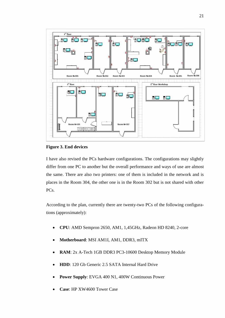
are on the third floor. The following plan (Figure 3) shows how the end devices and
network plugs are placed in the building.
21
Figure 3. End devices
I have also revised the PCs hardware configurations. The configurations may slightly
differ from one PC to another but the overall performance and ways of use are almost
the same. There are also two printers: one of them is included in the network and is
places in the Room 304, the other one is in the Room 302 but is not shared with other
PCs.
According to the plan, currently there are twenty-two PCs of the following configura-
tions (approximately):
CPU: AMD Sempron 2650, AM1, 1,45GHz, Radeon HD 8240, 2-core
Motherboard: MSI AM1I, AM1, DDR3, mITX
RAM: 2x A-Tech 1GB DDR3 PC3-10600 Desktop Memory Module
HDD: 120 Gb Generic 2.5 SATA Internal Hard Drive
Power Supply: EVGA 400 N1, 400W Continuous Power
Case: HP XW4600 Tower Case

22
As it is seen on the device map, there is a twenty-third PC. However, it is now used as
a file server. The hardware configurations are approximately the same as the other
twenty-two PCs. There is no server OS installed and configured and no advanced rules
or features are implemented. However, there is a file share that can be accessed, modi-
fied, altered and deleted from the other PCs.
3.1.2 Network map
“Petrocast Silica” has one public IP address that they rent from the Internet Service
Provider. I do not reveal the IP address because of security reasons. Their Local Area
Network consists of one router and three switches that are connected according to the
common bus network topology (see Figure 4): the router is connected to the first
switch on the third floor, this switch is connected to the one that is on the first floor of
the building, and, finally, the second switch is connected to the last switch that is situ-
ated in the Workshop on the first floor.
Figure 4. Brief network map
23
3.2 Network configurations
In this section I suggest some improvements for the current network design and im-
plementations. However, I am going to list several techniques that are not supported
by the equipment that is already configured for this network so I am going to choose
new network equipment.
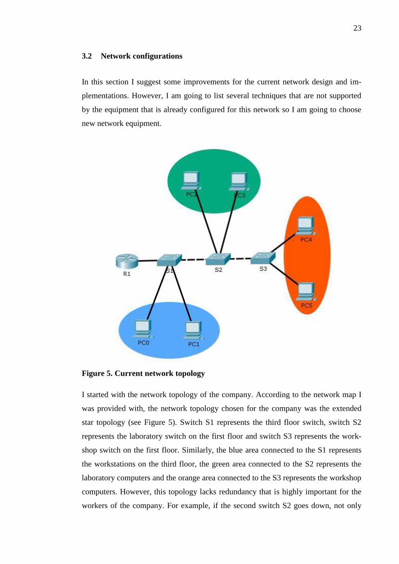
Figure 5. Current network topology
I started with the network topology of the company. According to the network map I
was provided with, the network topology chosen for the company was the extended
star topology (see Figure 5). Switch S1 represents the third floor switch, switch S2
represents the laboratory switch on the first floor and switch S3 represents the work-
shop switch on the first floor. Similarly, the blue area connected to the S1 represents
the workstations on the third floor, the green area connected to the S2 represents the
laboratory computers and the orange area connected to the S3 represents the workshop
computers. However, this topology lacks redundancy that is highly important for the
workers of the company. For example, if the second switch S2 goes down, not only
24
the laboratory loses the connection to the LAN and the Internet, but also the workshop
and its computers too.
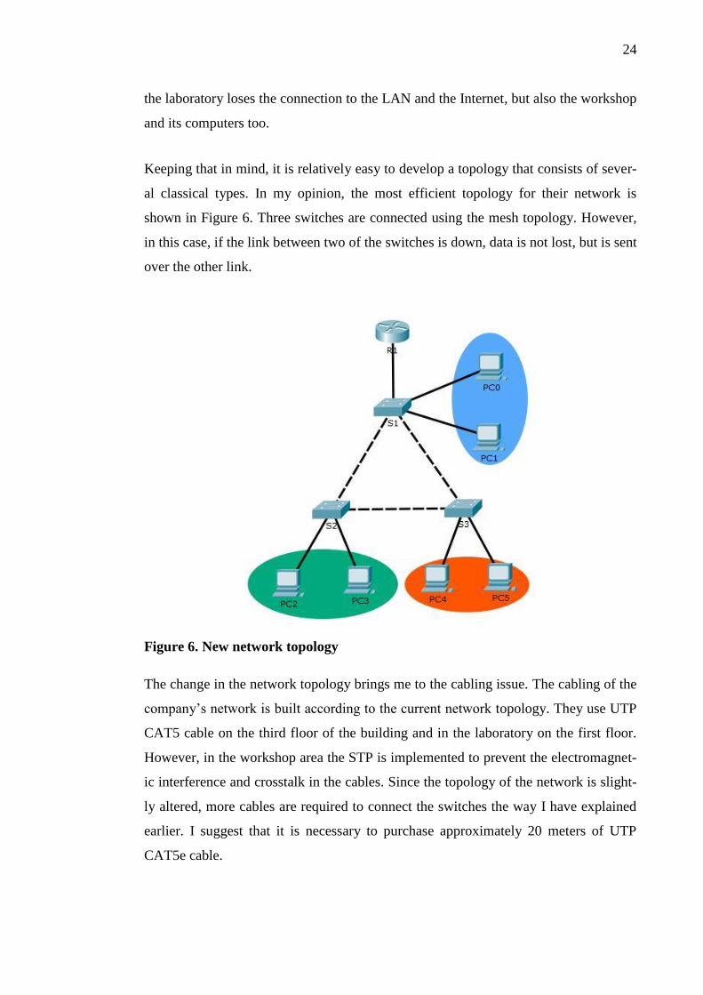
Keeping that in mind, it is relatively easy to develop a topology that consists of sever-
al classical types. In my opinion, the most efficient topology for their network is
shown in Figure 6. Three switches are connected using the mesh topology. However,
in this case, if the link between two of the switches is down, data is not lost, but is sent
over the other link.
Figure 6. New network topology
The change in the network topology brings me to the cabling issue. The cabling of the
company’s network is built according to the current network topology. They use UTP
CAT5 cable on the third floor of the building and in the laboratory on the first floor.
However, in the workshop area the STP is implemented to prevent the electromagnet-
ic interference and crosstalk in the cables. Since the topology of the network is slight-
ly altered, more cables are required to connect the switches the way I have explained
earlier. I suggest that it is necessary to purchase approximately 20 meters of UTP
CAT5e cable.

25
After the necessary changes in network topology and the cabling are done, the net-
work scheme of the company is similar to one on Figure 7, where the third floor
switch is in the upper left corner named S1 and is connected to the fourteen work-
stations, the laboratory switch S2 is in the lower left corner and connects together six
laboratory workstations and the workshop switch S3 is in the lower right corner of the
picture, connecting two workshop computers to the network.
Figure 7. Cabled network with workstations
Figure 7 shows only one router in the whole network. It means that currently there is
no need to implement any of the routing protocols. However, in case of the company’s
expansion, it is wise to pre-select a router that supports at least the most common rout-
ing protocols, such as OSPF and EIGRP mentioned earlier. As a suitable example of a
router I have chosen a refurbished Cisco 1841 router with two LAN ports and support
of the BGP, OSPF, EIGRP and RIP routing protocols. It is always more reliable to
buy brand new equipment. However, in case of Petrocast Silica, new Cisco equipment
is too expensive and too unknown to buy. Instead, I decided to advise them to buy a
refurbished router whose price is significantly lower but the quality is still high. Simi-

26
larly, I decided to select three Cisco 2950-24 refurbished switches for several reasons.
To start with, this switch model has 24 10/100 Mbps ports which is enough for the
current state of the company’s network. Although there are more advanced switches
for almost the same price, I decided that the features that make them more advanced
(for example, optical fiber cable support) are unnecessary for the company at this
time.
The switches bring us to VLAN configurations. For this project, I have decided to set
up DHCP for multiple VLANs. There are five groups of users in the company’s net-
work – Head department with two users, Research & Development department with
seven users, Marketing & Sales department with five users, Laboratory department
with seven users and Workshop department with two users. At first, my idea was to
set up VLANs and assign each user an IP address manually. However, in case there
are more workstations and more users coming to the company, the manual approach
will prove to be difficult and time-consuming. Instead, I have decided to use sub-
interfaces of the router and to assign IP addresses automatically, choosing them from
the pool of available IP addresses.
To make the DHCP work, it is necessary to enable the sub-interface, then enable the
encapsulation, state the specific VLAN number for which the DHCP is set and then
specify the IP address for the sub-interface.
R1(config)# interface FastEthernet0/0.10
R1(config-subif)# encapsulation dot1Q 10
R1(config-subif)# ip address 10.10.10.1 255.255.255.0
Similarly, the other four sub-interfaces:
R1(config)# interface FastEthernet0/0.20
R1(config-subif)# encapsulation dot1Q 20
R1(config-subif)# ip address 10.10.20.1 255.255.255.0
R1(config)# interface FastEthernet0/0.30
R1(config-subif)# encapsulation dot1Q 30
R1(config-subif)# ip address 10.10.30.1 255.255.255.0

27
R1(config)# interface FastEthernet0/0.40
R1(config-subif)# encapsulation dot1Q 40
R1(config-subif)# ip address 10.10.40.1 255.255.255.0
R1(config)# interface FastEthernet0/0.50
R1(config-subif)# encapsulation dot1Q 50
R1(config-subif)# ip address 10.10.50.1 255.255.255.0
I have also set the native VLAN 1 and management VLAN 99 as follows:
R1(config)# interface FastEthernet0/0.1
R1(config-subif)# encapsulation dot1Q 1 native
R1(config-subif)# ip address 10.10.1.1 255.255.255.0
R1(config)# interface FastEthernet0/0.99
R1(config-subif)# encapsulation dot1Q 99
R1(config-subif)# ip address 10.10.99.1 255.255.255.0
After that, it is necessary to set up the switch interfaces as trunk ports – the interfaces
that are carrying traffic from the different VLANs simultaneously. In my case, the
trunk interfaces are Switch 1 Port Fa0/1, Port Fa0/2 and Port Fa0/4, Switch 2 Port
Fa0/2 and Port Fa0/3 and Switch 3 Port Fa0/3 and Port Fa0/4.
S1(config)# interface FastEthernet0/1
S1(config-if)# switchport mode trunk
S1(config)# interface FastEthernet0/2
S1(config-if)# switchport mode trunk
S1(config)# interface FastEthernet0/4
S1(config-if)# switchport mode trunk
S2(config)# interface FastEthernet0/2
S2(config-if)# switchport mode trunk
S2(config)# interface FastEthernet0/3
S2(config-if)# switchport mode trunk
S3(config)# interface FastEthernet0/3
S3(config-if)# switchport mode trunk
28
S3(config)# interface FastEthernet0/4
S3(config-if)# switchport mode trunk
Also, for each of the switches I have set a management VLAN interface. Management
VLAN is generally used to access the switches’ features remotely – through Telnet or
SSH – and to change the configurations, if necessary.
S1(config)# interface vlan 99
S1(config-if)# ip address 10.10.99.10 255.255.255.0
S1(config)# ip default-gateway 10.10.99.1
S2(config)# interface vlan 99
S2(config-if)# ip address 10.10.99.20 255.255.255.0
S1(config)# ip default-gateway 10.10.99.1
S3(config)# interface vlan 99
S3(config-if)# ip address 10.10.99.30 255.255.255.0
S1(config)# ip default-gateway 10.10.99.1
Next, I need to assign the ports that are used by the workstations to the corresponding
VLANs. For that, I have decided to use VLAN 10 for the Head department users,
VLAN 20 for Research & Development department users, VLAN 30 for Marketing &
Sales department users, VLAN 40 for Laboratory department users and VLAN 50 for
the Workshop department users. Ports from 10 to 14 and ports 21 and 22 on Switch 1
belong to the VLAN 20, ports 15 and 16 – to the VLAN 10, ports from 17 to 20 and
port 23 – to VLAN 30. Ports from 10 to 15 on Switch 2 belong to VLAN 40. Finally,
ports 10 and 11 on Switch 3 belong to VLAN 50. The following configurations show
the port assignments on Switch 1:
interface FastEthernet0/10
switchport access vlan 20
switchport mode access
spanning-tree portfast
!
interface FastEthernet0/11
switchport access vlan 20

29
switchport mode access
spanning-tree portfast
!
interface FastEthernet0/12
switchport access vlan 20
switchport mode access
spanning-tree portfast
!
interface FastEthernet0/13
switchport access vlan 20
switchport mode access
spanning-tree portfast
!
interface FastEthernet0/14
switchport access vlan 20
switchport mode access
spanning-tree portfast
!
interface FastEthernet0/15
switchport access vlan 10
switchport mode access
spanning-tree portfast
!
interface FastEthernet0/16
switchport access vlan 10
switchport mode access
spanning-tree portfast
!
interface FastEthernet0/17
switchport access vlan 30
switchport mode access
spanning-tree portfast
!
interface FastEthernet0/18
switchport access vlan 30
switchport mode access
spanning-tree portfast
!
interface FastEthernet0/19
switchport access vlan 30
switchport mode access
spanning-tree portfast

30
!
interface FastEthernet0/20
switchport access vlan 30
switchport mode access
spanning-tree portfast
!
interface FastEthernet0/21
switchport access vlan 20
switchport mode access
spanning-tree portfast
!
interface FastEthernet0/22
switchport access vlan 20
switchport mode access
spanning-tree portfast
!
interface FastEthernet0/23
switchport access vlan 30
switchport mode access
spanning-tree portfast
Similarly, the configurations are applied to the Switch 2 and Switch 3. The spanning-
tree portfast command is used here and increase the speed of assigning IP ad-
dresses using DHCP. However, to prevent loops from occurring in the network,
BPDU Guard was turned on too. For this network, five different DHCP pools are nec-
essary. I have decided to use a new network for each of the pool – network
10.10.10.0/24 for VLAN 10, network 10.10.20.0/24 for VLAN 20, network
10.10.30.0/24 for VLAN 30, network 10.10.40.0/24 for VLAN 40 and network
10.10.50.0/24 for VLAN 50. The following configurations describe each pool of ad-
dresses for each VLAN:
ip dhcp pool Head
network 10.10.10.0 255.255.255.0
default-router 10.10.10.1
ip dhcp pool R&D
network 10.10.20.0 255.255.255.0
default-router 10.10.20.1
ip dhcp pool M&S
network 10.10.30.0 255.255.255.0
default-router 10.10.30.1
ip dhcp pool Lab

31
network 10.10.40.0 255.255.255.0
default-router 10.10.40.1
ip dhcp pool WS
network 10.10.50.0 255.255.255.0
default-router 10.10.50.1
One of the options that may be of use is to exclude the first ten IP addresses from each
pool. The reason for that might be a new device connected to the network or simply a
need of a spare IP address. However, the responsible person of the company made it
clear that these precautions are not necessary since hardly any new devices are going
to be connected to the network in the nearest future. After that, all the devices in the
network have the IP addresses from the IP address pools where they belong. The fig-
ure below shows a workstation from the Head department with the IP address from the
pool for VLAN 10 and a workstation from the Laboratory department with the IP ad-
dress from the pool for VLAN 30. The following picture (Figure 8) shows the correct-
ly assigned IP addresses.
Figure 8. DHCP for the different VLANs
The next thing I have decided to implement is NAT overload. In my opinion, for the
simplicity of the network design and implementation it is convenient to use dynamic
NAT, as there is only one public IP address provided to the company by the ISP, but
there are many private IP addresses in the local network.

32
To configure NAT overload, or PAT, it is necessary to first set the inside interface and
the outside interface. For the inside interface I have Port Fa0/0 on R1. Similarly, for
the outside interface I have Port Fa0/1 on the same R1.
R1(config)# interface FastEthernet0/0
R1(config-if)# ip nat inside
R1(config)# interface FastEthernet0/1
R1(config-if)# ip nat outside
After that, it is necessary to configure an ACL that includes private IP addresses from
the Local Area Network. An ACL is needed to list the particular host on the LAN.
Then, an ACL is applied to the NAT overload configuration.
R1(config)# ip nat inside source list 1 interface FastEthernet0/1
overload
The previous command states that the source of the IP addresses that are on the inside
interface are in the list number one and the outside port for these configurations is port
FastEthernet0/1.
I have also decided to implement a Link Aggregation Control Protocol between the
switches. Link Aggregation Control Protocol allows to merge several links between
two devices into one to increase the bandwidth of the link and the security too. This
means that in case one link is down, the other one takes its place without interrupting
the connection. To implement LACP, it is necessary to put the ports of the future
merged link into a trunk state. Since I already have two trunk ports on each of the
switches, it is necessary to turn on two more ports on each of the switches and set up
the trunking mode. For the Switch 1 I have chosen ports Fa0/2 and Fa0/5 to be the link
to Switch 2 with ports Fa0/2 and Fa0/5 respectively. For the link between Switch 2
and Switch 3 I have chosen ports Fa0/3 and Fa0/6 on both sides. For the link between
Switch 3 and Switch 1 I have chosen ports Fa0/4 and Fa0/7 on both sides. After the
necessary ports have been turned on and switched to trunk mode, I have merged the
ports of each link into a single channel with active mode.
S1(config)# interface Fa0/5

33
S1(config-if)# switchport mode trunk
S1(config)# channel-group 1 mode active
S1(config)# no shutdown
The same configurations are applied to the other ports of the link between the first and
the second switches. The link between the second and the third switches carries group
number 2 while the link between the first and the third switches carries group number
3. After these changes are made to the topology, the network scheme looks like that
(see Figure 9).
Figure 9. DHCP for the different VLANs
The group channels are also visible through the show etherchannel command:
S1#show etherchannel
Channel-group listing:
----------------------
Group: 1
----------
Group state = L2
Ports: 2 Maxports = 16
Port-channels: 1 Max Port-channels = 16
Protocol: LACP

34
Group: 3
----------
Group state = L2
Ports: 2 Maxports = 16
Port-channels: 1 Max Port-channels = 16
Protocol: LACP
3.3 End devices
In this part of my research I am going to explain the changes in PCs’ and server’s con-
figurations – both hardware and software. I have also calculated the pricing for these
changes.
3.3.1 PC configurations
One thing I have noticed about the PCs` configurations is that they have several dif-
ferent operating systems installed. For example, two laptops that belong to the Head
department have Windows XP installed on them while the most powerful computer in
the Research & Development department has Windows 7. All in all, there are six PCs
with Windows 7 and fourteen PCs with Windows XP. The “file server” has Windows
XP too.
Although different operating systems can significantly increase the time to trouble-
shoot some problems or to find necessary drivers and programs, in case of this com-
pany I have decided to leave the operating systems the way they are now. There are
some reasons for my decision – first of all, new operating systems will cost a signifi-
cant amount of money that the head of the company is not ready to spend at least right
now. The second reason is that the hardware configurations of the PCs are not good
enough to support newest operations system like Windows 8 or Windows 10. In fact,
some of the PCs can hardly manage Windows 7. There is another option – almost any
free Linux distributive can be installed to these PCs so that they might work even a
little bit faster than now but it will take a lot of time for users to adjust to the new op-
erating system and get used to new gestures, commands and features.
However, I have decided to change four old laptops (two in the Head department and
two in Research & Development department) to PCs because the hardware configura-

35
tions of these laptops cannot deal with a lot of everyday tasks like multiple browser
windows. The hardware configurations of these PCs are listed in the Table 2.
Table 2. New PCs` hardware configurations
Device Name
CPU AMD Sempron 2650, AM1, 1,45GHz, Radeon HD 8240, 2-core
Motherboard MSI AM1I, AM1, DDR3, mITX
RAM 2x A-Tech 1GB DDR3 PC3-10600 Desktop Memory Module
HDD 120 Gb Generic 2.5 SATA Internal Hard Drive
Power supply EVGA 400 N1, 400W Continuous Power
Case P XW4600 Tower Case
The aapproximate cost of one PC with hardware configurations listed in Table 4 does
not exceed EUR 100, assuming that the company has four spare copies of the Win-
dows 7 operating system.
However, new PCs require new software like simple office suite for working with
tables, texts and presentations and new anti-virus software. I am going to tell more
about anti-virus in the next part of my thesis as well as about other security measures.
For the office suite I suggest using LibreOffice 5.1.1. This version is the last stable
one for the moment and it is free for use. LibreOffice is visually quite similar to Mi-
crosoft Office programs, so the users do not spend much time to get used to the new
software.
I also suggest some new rules and changes to the usual way of doing things in the
company. First of all, I recommend enabling the feature that downloads critical up-
dates for the operating system, but disable the feature that installs them automatically.
This way users’ PCs will have pending updates but the system administrator will in-
stall them instead of users. In my opinion, this solution will help to prevent almost all
human factor problems during the installation (like accidentally turning off the PC
during the update running). There is another way: system administrator can remotely
update every PC without walking from one office to another. This option, however,
requires a remote connection to users` PCs like Windows Remote Desktop Connec-
tion, TeamViewer or similar software. I also recommend that the system administrator
installs not only updates but also necessary software instead of users. This way it is

36
possible to keep track of the installed programs and prevent some troubles during the
installation process.
3.3.2 Server configurations
As I have mentioned before, there is another PC. Its main purpose is to provide other
users with data from the shared folder. As far as I know, users are allowed to create,
change, modify and delete files in this folder. There are no other permissions for these
files and no other purpose for this PC. Hardware configurations of this PC are the
same as the other PCs, however, there is no server OS installed. So, technically, it is
not entirely correct to name this PC a server, although I have several solutions to this
problem.
First, it is possible to install Server OS (probably Windows Server 2012) instead of
usual user OS. This way it is possible to configure security features like permissions,
user groups and restrictions so that the access to the document would be controlled
and monitored. On one hand, this solution is more secure than the one that is already
implemented because Server OS is generally suits better for dealing with multiple user
access than User OS. On the other hand, this solution may require additional spending
on new hardware because current hardware is not the most reliable one.
There are several types of permissions that can be set to files and/or folders on a serv-
er. These permissions exist to specify the level of access that one has to a certain doc-
ument or folder and, if necessary, to restrict it. The permission types and features de-
pend also on the type of folder that is set by an administrator or other responsible per-
son. The Share permission and NTFS permission are the most common ones. The dif-
ference between them is visible when the user accesses the necessary file in different
ways. If the user has Share permission, the he or she is able to access the file – from
his or her workstation via a specific share. If the user has an NTFS permission, he or
she is able to access the file while logged in to the server.
The Share permission settings can be: “Read”, “Change” or “Full Control”. Clearly,
“Read” permission does not allow any modifications to the file, “Change” permission
allows rewriting but not moving or deleting the file. “Full Control” gives a user an
ability to read, write, modify or delete the file. The affected are users, certain groups

37
of users or all users and groups at once. The following picture (Figure 10) shows an
example of Share permissions applied to a certain folder.
Figure 10. Share permissions.
The NTFS permissions are more various. While Read and Full Control permissions
mean the same as with the Share permissions, the others are different. List Folder
Contents allow users to view the inside of the folder, Write allows them to add new
files. Read and Execute makes it possible to view the files themselves and run them
and Modify allows changing the files in the said folder. The difference between the
Share and NTFS permissions is visible in Figure 11.
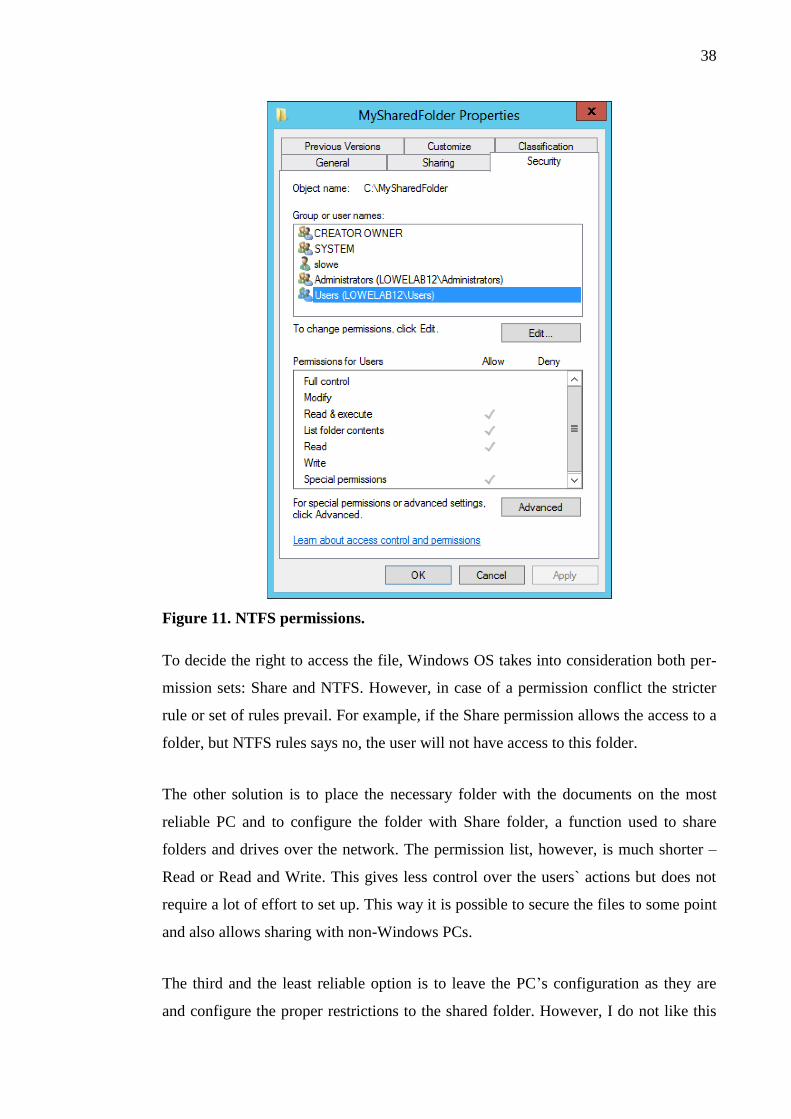
38
Figure 11. NTFS permissions.
To decide the right to access the file, Windows OS takes into consideration both per-
mission sets: Share and NTFS. However, in case of a permission conflict the stricter
rule or set of rules prevail. For example, if the Share permission allows the access to a
folder, but NTFS rules says no, the user will not have access to this folder.
The other solution is to place the necessary folder with the documents on the most
reliable PC and to configure the folder with Share folder, a function used to share
folders and drives over the network. The permission list, however, is much shorter –
Read or Read and Write. This gives less control over the users` actions but does not
require a lot of effort to set up. This way it is possible to secure the files to some point
and also allows sharing with non-Windows PCs.
The third and the least reliable option is to leave the PC’s configuration as they are
and configure the proper restrictions to the shared folder. However, I do not like this
39
solution, because, as I was told, this PC tends to reboot itself and generally runs slow-
er than the others. Still, this is the cheapest option because the company will not need
to spend anything. However, the previous option seems more reliable to me and it is
also free of charge.
In my opinion, it is more convenient to implement a shared folder on a newer PC in-
stead of using an old PC or install a server OS there. The reason is that it requires a
decent amount of time to install and configure the server OS, but it takes a lot less
time to copy the files to a newer PC and make a shared folder. In my opinion, it is also
unwise to make a server out of the old PC, because its hardware configurations are
hardly suitable for that. So in order to make a server it is necessary to build a new set
of hardware configurations and that costs money. However, they can be saved by im-
plementing a shared folder on a newer PC.
Although the place where the files are stored is a PC, it is necessary to apply some
additional rules to restrict physical access to the PC and the sharing settings. I recom-
mend to grant the “Full Control” permissions to administrative account and enable
remote access to the PC for the administrator in order to save the time and configure
everything from his office.
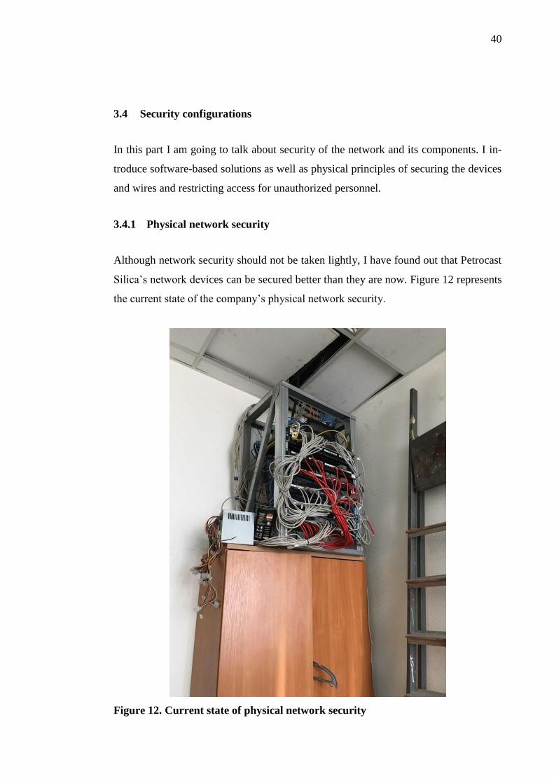
40
3.4 Security configurations
In this part I am going to talk about security of the network and its components. I in-
troduce software-based solutions as well as physical principles of securing the devices
and wires and restricting access for unauthorized personnel.
3.4.1 Physical network security
Although network security should not be taken lightly, I have found out that Petrocast
Silica’s network devices can be secured better than they are now. Figure 12 represents
the current state of the company’s physical network security.
Figure 12. Current state of physical network security

41
According to the picture, the devices are almost impossible to differ from one another
and the cables are slightly messed up. Also, it is possible to open the lock of the room
with any key from the same floor`s rooms. This might be convenient to some extent in
sense of having an access to the devices all the time but this fact also presents a great
security threat to the network. I suggest that the lock for this door is replaced for a
unique one. Also, I find it more suitable that only the network administrator has phys-
ical access to this room and the devices that are inside.
I find worrying not only the security state of the devices themselves but also of the
wires too. It is troublesome when the wires are not possible to distinguish one from
another. However, when the wires and the power sockets are in disorder, this can lead
to serious danger like short-circuit or even fire. The Figure 13 below shows one of the
UPS`s power socket blocks that are situated under the table. The plastic cover and the
wires are frequently damaged by the moving office chair.
Figure 13. UPS wiring.

42
In addition to that, I find it necessary to implement a labeling system. There are not so
many end devices in the network, and therefore, not so many wires, but it is still pos-
sible to mix the wires up, if they are not in order. A labeling system is easy to use and
helps to keep track of the physical connections on the network device. The main point
of this system is to name every wire that is connected to a device and put a sticker
with its name on it. It is also a good practice to put the devices in a closed rack with a
lock on it. I have recommended this solution to the Head of the company but he has
found it unnecessary. However, it is still possible to keep a good level of security
without locking up the devices.
3.4.2 Software-based network security
There are several ways to prevent the network from malicious software and attacks.
More and more advanced technologies are developing constantly. But, in case of this
company it is important to think not only about the security features, but also about
the price of devices that support them.
I suggest that it is necessary to enable security features like BPDU Guard on the
switches to prevent loops and connectivity issues in the network. Bridge Protocol Data
Unit Guard prevents the port (usually the trunk port) from receiving the Spanning-
Tree Protocol Bridge Protocol Data Units. However, the port is able to send STP
BPDUs. When the port receives an STP BPDU, it goes to an error-disabled state and
may be enabled manually again. This means that, if there is an unauthorized switch
being connected to a network, the trunk port receives the BPDU message from this
switch and goes to a disabled state, at the same time preventing the data packets from
the new switch to go into a network. This is a common way to secure the network. I
strongly recommend using passwords, too, to prevent unauthorized access to the con-
sole. The passwords should be different from one another (privileged and global con-
figuration modes) and they need to be long enough not to be guessable. A password
policy might be created to regulate the complexity of the passwords both for network
and end devices.

43
3.4.3 Physical security of end devices
As I have mentioned earlier, the rooms where the PCs are located are usually locked if
there is no one inside. They are also closed during the night. In addition to that, the
building has restriction access policy so that everyone who goes inside uses an access
card at the front door of a building. However, this policy did not prevent me from go-
ing inside the building, up to the third floor and in the Deputy Director`s cabinet. It
means that people working there can bring to work anyone they want without any
problem. I suggest that the restriction policy for entering the building is followed
stricter than currently. Overwise, physical security of end devices is on a decent level
that is suitable for the company with certain size and objectives.
3.4.4 Software-based security of end devices
There are a lot of ways to secure the information that is stored on users` PCs. I suggest
that the anti-virus program is installed on every PC in the company. I recommend to
use either free anti-virus software like Avira or commercial ones like Avast or Syman-
tec. This anti-virus software usually provides end user with a set of rules, restrictions
and checks that help the user to keep the data safe. As I have said earlier, the installa-
tion is to be run by a network administrator to prevent possible issues during the pro-
cess.
Another practice is to use a log-in password to prevent the access to any unauthorized
personnel. I suggest that the password is to be at least eight characters long and con-
tain upper- and lower-case letters, at least one number and at least one symbol. In ad-
dition to that, the passwords are to be changed every one-two months. This period
might be slightly altered in case of any unpredicted situations.

44
4 CONCLUSIONS
The aim of this project was to get familiar with Petrocast Silica company, with its
network and network devices and study its needs to develop a strategy of possible
improvements. During this process I have found out that the company’s LAN and
network devices can be changed and upgraded. For example, the network was built
using bus topology – quite popular yet not secure enough. Also, the PCs were all us-
ing several versions of the operating systems as well as other software. My intention
was to develop a new network topology including new network setting and suggest
some improvements for the end devices.
The theoretical part of my study contains the main methods and principles that are
used in modern LANs of small- and medium-sized companies. Although I have listed
easy-to-implement techniques as well as advanced ones, my goal in the practical part
was not only to improve the current network, but also use simple and clear methods.
The reason for that is that the staff is mainly focused on the company’s market success
in the area of fireproof concrete and various gun mixtures rather that education in the
area of IT. In that sense, my aim was to create a network design that is at the same
time useful and easy to maintain. This is also the reason why I tried to avoid any tech-
nologies that are hard to understand and set up – like Linux or Active Directory. The
other reason for that is the technologies and software usually require maintenance
from time to time no matter how well they were set up and adjusted in the first place.
Usually the maintenance is done by the network administrator of the company. How-
ever, when I spoke to him about these improvements, he doubted that he was able to
maintain such network.
In the practical part of my thesis I created a network prototype for Petrocast Silica. For
that, I was using real equipment as well as the Packet Tracer 6.2 software. The final
version of the network was done in Packet Tracer using the technologies I have listed
in the theoretical part. I have also suggested some methods for improving the current
state of the PCs such as using the same software versions, changing four old PCs and
laptops to newer ones and locking up the network devices in the office as a security
measure.

45
I have completed the project in six months – from gathering the information necessary
for strategy development to the last corrections in this document. Although the theme
of my project is quite vast, I have decided to focus on the main points only, keeping in
mind that there are a lot of modern and advanced methods and technologies in design-
ing, building and securing the network but the company that hired me for this research
does not exactly need all the high-end techniques. Overall, I find the results of this
project successful.
However, as a future improvement, it is possible to think of a way how to simplify the
network maintenance and make it more secure. As a practical improvement, I suggest
Linux implementing on a PC that acts as a file server – it may be difficult for the staff
to get used to the new operating system but Linux has proved itself to be quite logical
and straightforward. Another good idea is to study deeply the company’s software
needs and PCs’ abilities in that sense – although I have suggested to use one version
of a software among all the workstations, some of them may perform better or worse
than the others. In this case, it is wise to look for a software that has different versions
(e.g. light or not very demanding and advanced) and implement it on the computers.
However, I have found out that the company is using mainly the office suite software
like Microsoft Office Word and Microsoft PowerPoint. It means that even if the work-
stations can perform differently, the software version might be the same. Still, few
alterations can be made.
Another improvement that I suggest is staff education. I agree that for some people it
might be difficult to follow all the technical improvements and developments but it is
very important at the same time to know the basic rules of using a PC – for example,
how to turn it on and off correctly, how to ensure data safety and integrity, what
measures prevent data loss etc.
However, there might be some problems for the company when following my sugges-
tions. One of the main troubles is to build and maintain the network that I have de-
signed for Petrocast Silica. The reason for that is that the network administrator of the
company might not fully understand the results of my research due to the lack of qual-
ification. This is why I suggested the staff education as one of the main improvements.

46
The results of my study can be used by those who face the same problems like Petro-
cast Silica’s – lack of network security and poor network design. Although the practi-
cal part suggests implementing the design that I have created specifically for Petrocast
Silica, the theoretical part contains a lot of useful information on the network topolo-
gies, protocols and devices that can be used to create new, more advanced network.
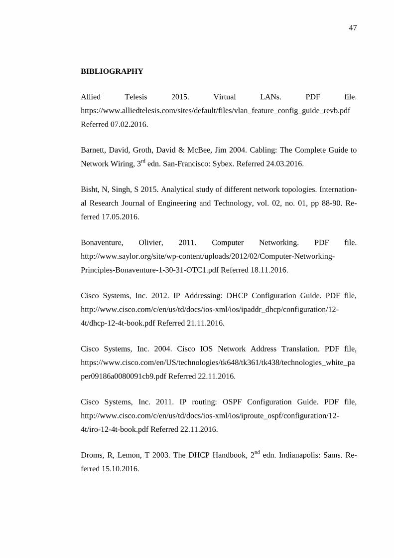
47
BIBLIOGRAPHY
Allied Telesis 2015. Virtual LANs. PDF file.
https://www.alliedtelesis.com/sites/default/files/vlan_feature_config_guide_revb.pdf
Referred 07.02.2016.
Barnett, David, Groth, David & McBee, Jim 2004. Cabling: The Complete Guide to
Network Wiring, 3rd
edn. San-Francisco: Sybex. Referred 24.03.2016.
Bisht, N, Singh, S 2015. Analytical study of different network topologies. Internation-
al Research Journal of Engineering and Technology, vol. 02, no. 01, pp 88-90. Re-
ferred 17.05.2016.
Bonaventure, Olivier, 2011. Computer Networking. PDF file.
http://www.saylor.org/site/wp-content/uploads/2012/02/Computer-Networking-
Principles-Bonaventure-1-30-31-OTC1.pdf Referred 18.11.2016.
Cisco Systems, Inc. 2012. IP Addressing: DHCP Configuration Guide. PDF file,
http://www.cisco.com/c/en/us/td/docs/ios-xml/ios/ipaddr_dhcp/configuration/12-
4t/dhcp-12-4t-book.pdf Referred 21.11.2016.
Cisco Systems, Inc. 2004. Cisco IOS Network Address Translation. PDF file,
https://www.cisco.com/en/US/technologies/tk648/tk361/tk438/technologies_white_pa
per09186a0080091cb9.pdf Referred 22.11.2016.
Cisco Systems, Inc. 2011. IP routing: OSPF Configuration Guide. PDF file,
http://www.cisco.com/c/en/us/td/docs/ios-xml/ios/iproute_ospf/configuration/12-
4t/iro-12-4t-book.pdf Referred 22.11.2016.
Droms, R, Lemon, T 2003. The DHCP Handbook, 2nd
edn. Indianapolis: Sams. Re-
ferred 15.10.2016.

48
Farell, M 2009. Virtual Local Area Networks. PDF document,
http://systems.digital.nhs.uk/infogov/security/infrasec/gpg/vlan.pdf Referred
14.11.2016.
Javvin Technologies Inc 2005. Network Protocols Handbook, 2nd
edn. Saratoga: Jav-
vin Technologies. Referred 21.11.2016.
Juniper Networks, Inc. 2016, OSPF configuration Guide. PDF document,
http://www.juniper.net/techpubs/en_US/junos12.3/information-products/pathway-
pages/config-guide-routing/config-guide-ospf.pdf Referred 21.11.2016.
Meghanathan, N 2014. Network Security: Attacks and Control. PDF file.
https://arxiv.org/ftp/arxiv/papers/1412/1412.6017.pdf Referred 11.11.2016.
Mikkeli University of Applied Sciences, Bachelor´s thesis guide, 2012. PDF Docu-
ment. http://student.mamk.fi/general/Uploads_files/helikoo/Bachelorthesisguide.pdf.
Referred 23.5.2013.
Mikkeli University of Applied Sciences, Reporting instructions, 2012. PDF document.
http://student.mamk.fi/showattachment.asp?ID=6957&DocID=3456. Referred
23.5.2013.
Molenaar, R 2011. How to master CCNP route. CreateSpace Independent Publishing
Platform. Referred 18.11.2016.
Molenaar, R 2011. How to master CCNP switch. CreateSpace Independent Publishing
Platform. Referred 18.11.2016.
Nokia 2003. A practical look at Network Address Translation. PDF document,
http://www.csd.uoc.gr/~hy435/material/whitepaper_technicalnetworkaddresstranslatio
n.pdf Referred 21.11.2016.
Samsung Electronics Co. 2014. Redundant Array of Independent Disks (RAID). PDF
document,
http://www.samsung.com/semiconductor/minisite/ssd/downloads/document/Samsung

49
_SSD_845DC_07_Redundant_Array_of_Independent_Disks_RAID.pdf Referred
22.11.2016.
Urkund plagiarism control tool web page. http://www.urkund.com/int/en/. Referred
23.5.2013.


