Journal of Mechanics Engineering and Automation 5 (2015) 95-106 doi: 10.17265/2159-5275/2015.02.006 Itaipu Binacional Hydro Power Plant Thrust Bearing Design Optimization for Higher Efficiency Piotr Pajaczkowski 1 , Michel Spiridon 1 , Andreas Schubert 1 , Geraldo Carvalho Brito Junior 2 and João Maria Marra 2 1. Alstom Renewable, Birr 5734, Switzerland 2. Itaipu Binacional, Foz do Iguacu 4108304, Brazil Received: December 17, 2014 / Accepted: January 05, 2015 / Published: February 25, 2015. Abstract: Hydro generators installed in Itaipu Binacional power plant with 824/737 MVA rated output power (50/60 Hz) belong to the largest ones in the world. Among many unique features, the generators are equipped with the largest hydrodynamic thrust bearings ever built (external diameter 5,200 mm, axial load equals approximately 3,600 t). This paper is an attempt to propose a new thrust bearing design with the use of the state-of-the-art technologies and simulation techniques that demonstrate a reduction of friction power losses generated by the thrust bearing. This paper is divided into two parts. Within the first one, the original thrust bearing design which was implemented in the generators is described. Related calculation results based on a TEHD (thermo-elasto-hydrodynamic) calculation software used by Alstom will be presented. A comparison between measurement results gathered in the 1980s is given. In the second part, a potential solution of a more beneficial bearing design is described. The proposed thrust bearing design modification is an implementation of Alstom’s Polypad TM coating. This modern polymer (PEEK) coating material has already been used by Alstom in projects around the world for many years. This coating allows pushing the operating parameters limits toward higher temperatures and lower oil film thicknesses far beyond the limits known for the conventional bearing materials. Key words: Hydrodynamic thrust bearings, simulations, measurements. 1. Introduction Hydro generators installed in Itaipu Binacional power plant with 824/737 MVA rated output power (50/60 Hz) belong to the largest ones in the world. Among many unique features, the generators are equipped with the largest hydrodynamic thrust bearings ever built (external diameter 5,200 mm, axial load can reach up to approximately 3,600 t). It has been more than 30 years since these thrust bearings were designed. During this time, some significant developments in bearing technologies as well as in simulation techniques have been observed. This paper is an attempt to propose a new thrust bearing design with the use of the state-of-the-art technologies and simulation techniques Corresponding author: Piotr Pajaczkowski, Ph.D., research fields: large hydrodynamic bearings simulations and measurements, rotor dynamics of vertically aligned machines. E-mail: [email protected]. that demonstrate a reduction of friction power losses generated by the thrust bearing and improve efficiency of the whole generator. The general idea is to bring the bearing design closer to the limits of the operational safety but without exceeding these limits. Operational safety limits for hydrodynamic bearings are described in Ref. [1] in details. This goal can be achieved only if the calculation methods allow maintaining satisfactory accuracy during the design phase. This study will show first of all validation of the calculation model with the use of measurement data. Afterwards, a comparison of an existing design (Fig. 1) with the new bearing proposal is described. Finally, the results of a heavily loaded thrust bearing under transient load are presented. The paper is organized as follows: Section 2 describes used calculation model; Section 3 presents the model validation and calculation results; finally, Section 4 gives the final conclusions. D DAVID PUBLISHING
Transcript
Journal of Mechanics Engineering and Automation 5 (2015) 95-106 doi: 10.17265/2159-5275/2015.02.006
Itaipu Binacional Hydro Power Plant Thrust Bearing
Design Optimization for Higher Efficiency
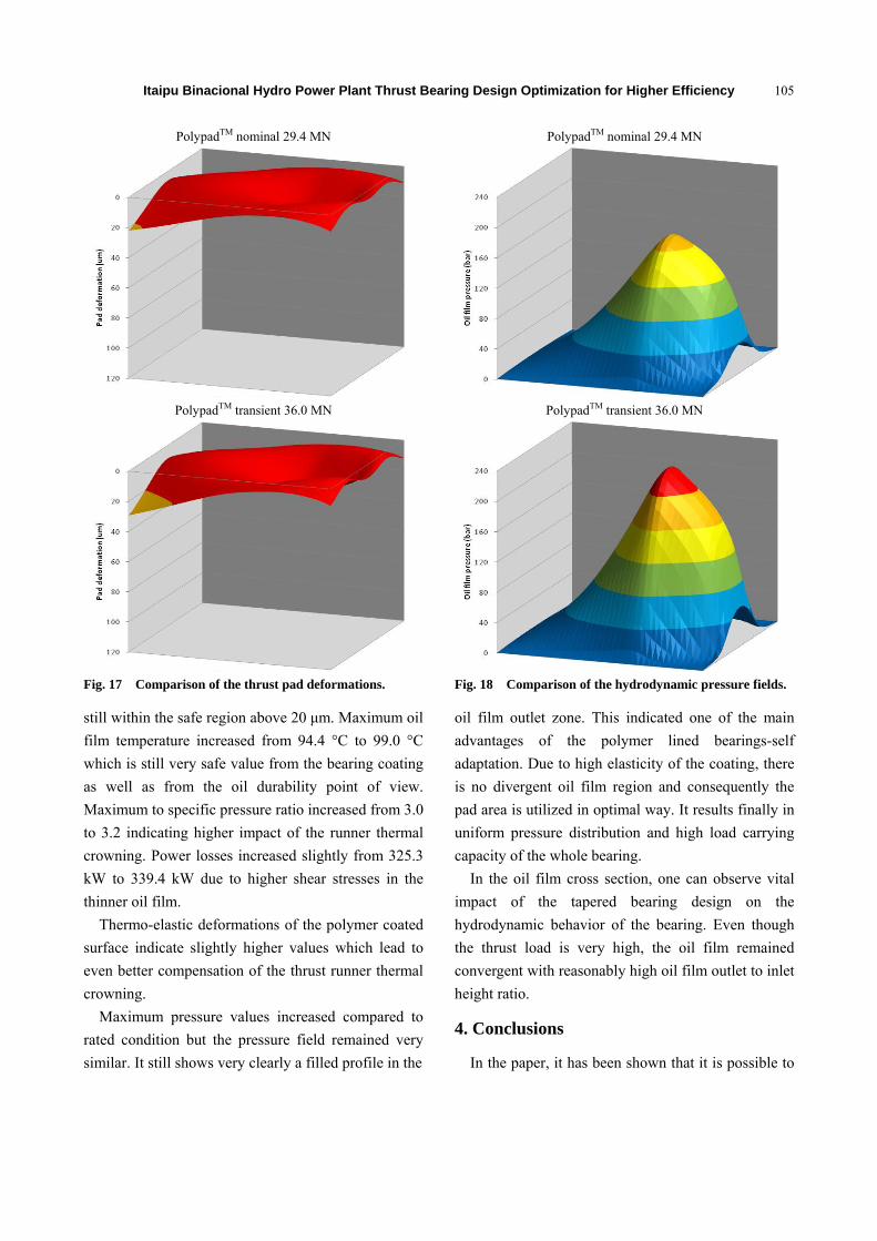
Piotr Pajaczkowski1, Michel Spiridon1, Andreas Schubert1, Geraldo Carvalho Brito Junior2 and João Maria
Marra2
1. Alstom Renewable, Birr 5734, Switzerland
2. Itaipu Binacional, Foz do Iguacu 4108304, Brazil
Received: December 17, 2014 / Accepted: January 05, 2015 / Published: February 25, 2015. Abstract: Hydro generators installed in Itaipu Binacional power plant with 824/737 MVA rated output power (50/60 Hz) belong to the largest ones in the world. Among many unique features, the generators are equipped with the largest hydrodynamic thrust bearings ever built (external diameter 5,200 mm, axial load equals approximately 3,600 t). This paper is an attempt to propose a new thrust bearing design with the use of the state-of-the-art technologies and simulation techniques that demonstrate a reduction of friction power losses generated by the thrust bearing. This paper is divided into two parts. Within the first one, the original thrust bearing design which was implemented in the generators is described. Related calculation results based on a TEHD (thermo-elasto-hydrodynamic) calculation software used by Alstom will be presented. A comparison between measurement results gathered in the 1980s is given. In the second part, a potential solution of a more beneficial bearing design is described. The proposed thrust bearing design modification is an implementation of Alstom’s PolypadTM coating. This modern polymer (PEEK) coating material has already been used by Alstom in projects around the world for many years. This coating allows pushing the operating parameters limits toward higher temperatures and lower oil film thicknesses far beyond the limits known for the conventional bearing materials. Key words: Hydrodynamic thrust bearings, simulations, measurements.
1. Introduction
Hydro generators installed in Itaipu Binacional
power plant with 824/737 MVA rated output power
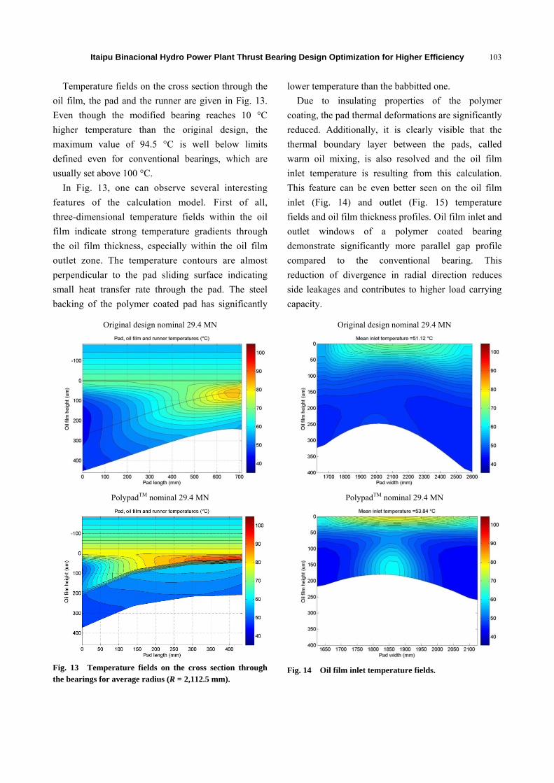
(50/60 Hz) belong to the largest ones in the world.
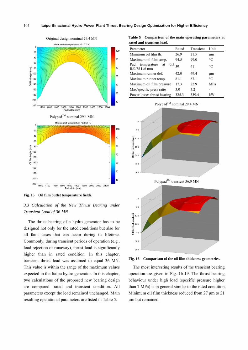
Among many unique features, the generators are
equipped with the largest hydrodynamic thrust bearings
ever built (external diameter 5,200 mm, axial load can
reach up to approximately 3,600 t). It has been more
than 30 years since these thrust bearings were designed.
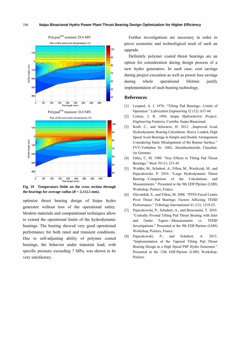
During this time, some significant developments in
bearing technologies as well as in simulation techniques
have been observed. This paper is an attempt to propose
a new thrust bearing design with the use of the
state-of-the-art technologies and simulation techniques
Corresponding author: Piotr Pajaczkowski, Ph.D., research
fields: large hydrodynamic bearings simulations and measurements, rotor dynamics of vertically aligned machines. E-mail: [email protected].
that demonstrate a reduction of friction power losses
generated by the thrust bearing and improve efficiency
of the whole generator. The general idea is to bring
the bearing design closer to the limits of the operational
safety but without exceeding these limits. Operational
safety limits for hydrodynamic bearings are described
in Ref. [1] in details. This goal can be achieved only if
the calculation methods allow maintaining satisfactory
accuracy during the design phase. This study will
show first of all validation of the calculation model
with the use of measurement data. Afterwards, a
comparison of an existing design (Fig. 1) with the new
bearing proposal is described. Finally, the results of a
heavily loaded thrust bearing under transient load are
presented. The paper is organized as follows: Section
2 describes used calculation model; Section 3 presents
the model validation and calculation results; finally,
Section 4 gives the final conclusions.
D DAVID PUBLISHING
Itaipu Binacional Hydro Power Plant Thrust Bearing Design Optimization for Higher Efficiency
96
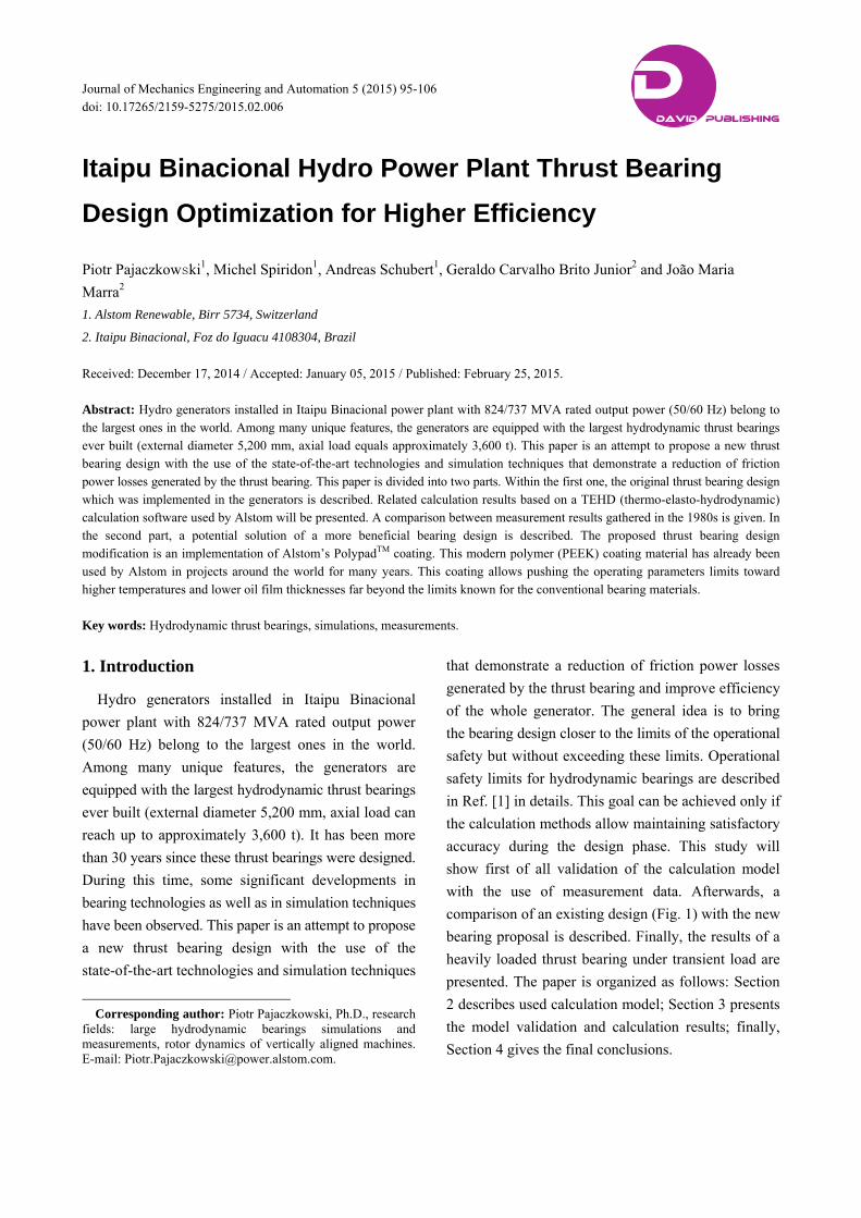
Fig. 1 Thrust bearing of an Itaipu hydro generator [2]: (1) thrust runner; (2) generator lower shaft; (3) thrust bearing oil to water heat exchanger; and (4) thrust pad.