IT Istruzioni per l’uso e manutenzione ALTERNATORI Istruzioni originali EN Operating and Maintenance Manual ALTERNATORS Translation based on the original Italian version ES Instrucciones para el uso y el mantenimiento ALTERNADORES Con la traducción de las istrucciones originales FR Mode d’emploi et d’entretien ALTERNATEURS Avec la traduction de la notice originale DE Gebrauchs und wartungsanleitung GENERATOREN Mit Übersetzung der ursprünglichen Anweisungen English SP - E1C Español Italiano Français Deutsch LA INSTALACIÓN DEBE SER REALIZADA SÓLO POR PERSONAL AUTORIZADO POR LINZ ELECTRIC SPA THE INSTALLATION MUST BE CARRIED OUT ONLY BY PERSONNEL AUTHORIZED BY LINZ ELECTRIC SPA L’INSTALLAZIONE DEVE ESSERE EFFETTUATA SOLO DA PERSONALE AUTORIZZATO DALLA LINZ ELECTRIC SPA L’INSTALLATION DOIT ÊTRE EFFECTUÉE UNIQUEMENT PAR DU PERSONNEL AUTORISÉ PAR LINZ ELECTRIC SPA DIE INSTALLATION DARF NUR DURCH AUTORISIERTES PERSONAL ERFOLGEN VON LINZ ELECTRIC SPA REVISIONE 2018.1
Transcript
IT Istruzioni per l’uso e manutenzione ALTERNATORI Istruzioni originali
EN Operating and Maintenance Manual ALTERNATORS Translation based on the original Italian version
ES Instrucciones para el uso y el mantenimiento ALTERNADORES Con la traducción de las istrucciones originales
FR Mode d’emploi et d’entretien ALTERNATEURS Avec la traduction de la notice originale
DE Gebrauchs und wartungsanleitung GENERATOREN Mit Übersetzung der ursprünglichen Anweisungen
Engl
ish
SP - E1C
Espa
ñol
Ital
iano
Fran
çais
Deu
tsch
LA INSTALACIÓN DEBE SER REALIZADA SÓLO POR PERSONAL AUTORIZADO POR LINZ ELECTRIC SPA
THE INSTALLATION MUST BE CARRIED OUT ONLY BY PERSONNEL AUTHORIZED BY LINZ ELECTRIC SPA
L’INSTALLAZIONE DEVE ESSERE EFFETTUATA SOLO DA PERSONALE AUTORIZZATO DALLA LINZ ELECTRIC SPA
L’INSTALLATION DOIT ÊTRE EFFECTUÉE UNIQUEMENT PAR DU PERSONNEL AUTORISÉ PAR LINZ ELECTRIC SPA
DIE INSTALLATION DARF NUR DURCH AUTORISIERTES PERSONAL ERFOLGEN VON LINZ ELECTRIC SPA
REVISIONE 2018.1
- 2 -
Arcole (Vr): Data del documento di consegna Date of the delivery document Fecha del documento de entrega Date du document de livraison Datum des Lieferdokuments
LINZ ELECTRIC SpaGiulio Pedrollo
Rappresentante legale - custode e detentore del Fascicolo TecnicoLegal representative - Keeper and holder of the Technical Dossier
Representante legal - Receptor y poseedor del Expediente TécnicoReprésentant légal - Responsable et détenteur du Dossier TechniqueRechtlicher Verteter - Aufbewahrer und Inhaber der technischen Akte
DECLARATION OF CONFORMITYAND INCORPORATION
The manufacturer LINZ ELECTRIC Spa - Viale del Lavoro, 30 - 37040 Arcole (VR) Italy, declares that the components described in this manual are manufactured in compliance with standards: EN 60034-1, EN 60204-1, EN 61000-6-2, EN 61000-6-4, EN 55014-1, EN 55011.They are therefore in conformity with the Direc-tives:- 2006/42/EC (Machinery Directive);- 2014/35/UE (Low Voltage);- 2014/30/UE (Electromagnetic Compatibil-
ity).Such conformity, the use of these ranges of components in machines that apply the Direc-tive 2006/42/EC, provided that their integration or their incorporation and/or assembly con-forms to, among other things, the rules of EN 60204 «Electrical equipment of Machines» and our installation instructions.The components defined above can not be put into service until the machinery into which they are incorporated has been declared in conform-ity with the applicable directives.Note: When the components are fed with specially adapted electronic converters and/or subservient to electronic monitoring and con-trol systems must be installed by a professional who assumes responsibility for compliance with the rules on electromagnetic compatibility regulations of the country in which it is installed machine.
DÉCLARATION DE CONFORMITÉET CONSTITUTION
Le fabricant LINZ ELECTRIC Spa - Viale del Lavoro, 30 - 37040 Arcole ( VR) Italie, déclare que les éléments décrits dans ce manuel sont fabriqués en conformité avec les normes: EN 60034-1, EN 60204-1, EN 61000-6-2, EN 61000-6-4, EN 55014-1, EN 55011.Ils sont donc en conformité avec les directives :- 2006/42/CE (Directive machines);- 2014/35/UE (Basse tension);- 2014/30/UE (Compatibilité Electromagné-
tique).Cette conformité, l’utilisation de ces gammes de composants dans les machines qui appliquent la directive 2006/42/CE, à condition que leur intégration ou leur incorporation et/ou le montage est conforme, entre autres choses, les règles de eN 60204 «Equipement électrique des machines» et nos instructions d’installation.Les composants définis ci-dessus ne peuvent pas être mis en service avant que la machine dans laquelle ils sont incorporés a été déclarée conforme aux directives applicables.Remarque: Lorsque les composants sont ali-mentés par des convertisseurs électroniques adaptés et/ou asservis à des systèmes de sur-veillance et de contrôle électronique doit être installé par un professionnel qui assume la res-ponsabilité de la conformité avec les règles sur les règles de la compatibilité électromagnétique du pays dans lequel il est installé machine.
DECLARACIÓN DE CONFORMIDADE INCORPORACIÓN
El fabricante LINZ ELECTRIC Spa - Viale del Lavoro, 30 - 37040 Arcole (VR) Italia, declara que los componentes descritos en este manual son fabricados de conformidad con las normas: EN 60034-1, EN 60204-1, EN 61000-6-2, EN 61000-6-4, EN 55014-1, EN 55011.Son, por tanto, de conformidad con las Direc-tivas:- 2006/42/CE (Directiva máquinas);- 2014/35/UE (Baja Tensión);- 2014/30/UE (Compatibilidad Electromag-
nética).Tal conformidad, el uso de estas gamas de com-ponentes en máquinas que aplican la Directiva 2006/42/CE, a condición de que su integración o su incorporación y/o montaje se ajusta a, entre otras cosas, las normas de EN 60204 «Equipo Eléctrico de las Máquinas» y las instrucciones de instalación.Los componentes definidos anteriormente no pueden ser puestos en servicio hasta que la maquinaria en la que están incorporados haya sido declarada en conformidad con las directivas aplicables.Nota: Cuando los componentes son alimenta-dos con convertidores electrónicos adaptados y/o amoldarse a los sistemas de supervisión y control electrónico debe ser instalado por un profesional que asume la responsabilidad por el cumplimiento de las normas relativas a la nor-mativa de compatibilidad electromagnética del país en el que está instalado máquina.
KONFORMITÄTSERKLÄRUNGUND EINGLIEDERUNG
Der Hersteller LINZ ELECTRIC Spa - Viale del Lavoro , 30 - 37040 Arcole (VR) Italien, er-klärt, dass die in diesem Handbuch beschriebe-nen Komponenten werden in Übereinstimmung mit den Normen: EN 60034-1, EN 60204-1, EN 61000-6-2, EN 61000-6-4, EN 55014-1, EN 55011. Sie sind daher in Übereinstimmung mit den Richtlinien:- 2006/42/EG (Maschinenrichtlinie);- 2014/35/UE (Niederspannung);- 2014/30/UE (Elektromagnetische Verträg-
lichkeit).Solche Konformität, die Verwendung dieser Bereiche von Komponenten in Maschinen, die in der Richtlinie 2006/42/EG gelten, vorausge-setzt, dass ihre Integration oder deren Einbau und/oder Montage entspricht, unter anderem den Regeln der EN 60204 «Elektrische Ausrüs-tung von Maschinen» und unsere Installations-anweisungen. Die oben definierten Komponen-ten nicht in Betrieb genommen werden, bis die Maschine, in die sie eingebaut werden, ist in Übereinstimmung mit den geltenden Richtlini-en erklärt werden.Hinweis: Wenn die Komponenten mit speziell angepassten elektronischen Konvertern und/oder unterwürfig elektronische Überwachungs-und Kontrollsysteme eingespeist muss von einem Fachmann, der die Verantwortung für die Einhaltung der Vorschriften zur elektromagne-tischen Verträglichkeit Vorschriften des Landes geht davon aus , in dem es installiert ist, instal-liert werden Maschine.
DICHIARAZIONE DI CONFORMITÀ E DI INCORPORAZIONE
Il costruttore LINZ ELECTRIC Spa - Viale del Lavoro, 30 - 37040 Arcole (Vr) Italia, dichia-ra che i componenti descritti in questo manuale, sono costruiti in osservanza alle norme: EN 60034-1, EN 60204-1, EN 61000-6-2, EN 61000-6-4, EN 55014-1, EN 55011.Sono quindi conformi alle Direttive:- 2006/42/CE (Direttiva Macchine);- 2014/35/UE (Bassa Tensione);- 2014/30/UE (Compatibilità Elettromagneti-
ca).Queste conformità consentono l’uso di queste gamme di componenti in macchine che appli-cano la Direttiva Macchine 2006/42/CE, con riserva che la loro integrazione o la loro incorpo-razione e/o assemblaggio siano effettuati con-formemente, tra l’altro, alle regole della norma EN 60204 «Apparecchiatura Elettrica delle Mac-chine» e alle nostre istruzioni d’installazione.I componenti sopra definiti non potranno essere messi in servizio prima che la macchina in cui sono incorporati sia stata dichiarata conforme alle direttive applicabili.Nota: Quando i componenti sono alimentati con convertitori elettronici adattati e/o asserviti a dispositivi elettronici di controllo e di coman-do, devono essere installati da un professionista che si assuma la responsabilità del rispetto delle regole sulla compatibilità elettromagne-tica vigenti nel Paese in cui viene installata la macchina.
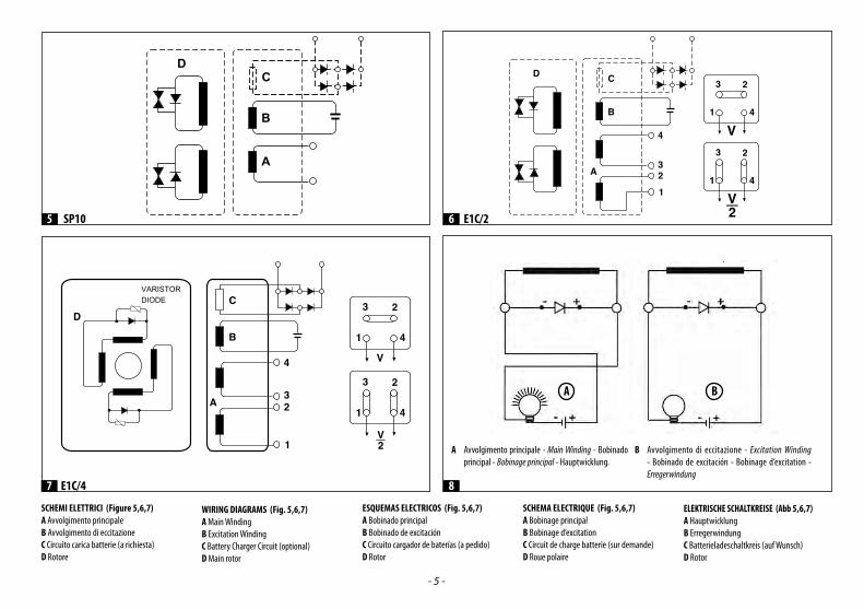
A Avvolgimento principale - Main Winding - Bobinado principal - Bobinage principal - Hauptwicklung.
A B
B Avvolgimento di eccitazione - Excitation Winding - Bobinado de excitación - Bobinage d’excitation - Erregerwindung
8
- 6 -
MISURE DI SICUREZZAPrima di utilizzare il gruppo elettrogeno è indispensabile leggere il manuale “Uso e manutenzione” del gruppo elettrogeno e dell’alternatore e seguire le seguenti raccomandazioni:⇒ Un funzionamento sicuro ed efficiente può essere raggiunto solo se le macchine vengono utilizzate in modo corretto,
secondo quanto previsto dai relativi manuali di “Uso e manutenzione” e dalle norme di sicurezza.⇒ Una scossa elettrica può causare gravi danni e addirittura la morte.⇒ È vietato togliere la calotta di chiusura della scatola collegamenti e le griglie di protezione dell’alternatore finché lo stesso
è in movimento e prima di avere disattivato il sistema di avviamento del gruppo elettrogeno.⇒ La manutenzione del gruppo deve essere effettuata esclusivamente da personale qualificato e specializzato.⇒ Non operare con indumenti “sciolti” in vicinanza del gruppo elettrogeno. Le persone addette alla movimentazione devono sempre indossare guanti da lavoro e scarpe antinfortunistiche. Qualora
il generatore o l’intero gruppo debba essere sollevato da terra, gli operai devono usare un casco protettivo. Nel presente manuale useremo dei simboli che hanno il seguente significato:
IMPORTANTE! si riferisce ad una operazione rischiosa o pericolosa che può causare danni al prodotto.
CAUTELA! si riferisce ad una operazione rischiosa o pericolosa che può danneggiare il prodotto e può causare ferite alle persone.
ATTENZIONE! si riferisce ad una operazione rischiosa o pericolosa che può causare gravi ferite o possibile morte.
PERICOLO!: si riferisce ad un rischio immediato che potrebbe causare gravi ferite o la morte.
L’installatore finale del gruppo elettrogeno è responsabile della predisposizione di tutte le misure necessarie a rendere l’intero impianto conforme alle vigenti norme locali di sicurezza (messa a terra, protezioni contro il contatto, protezioni contro le esplosioni e l’incendio, arresto di emergenza, ecc…).
DESCRIZIONE DELL’ALTERNATOREGli alternatori della serie SP - E1C/2 - E1C/4 sono monofasi, a due o quattro poli, senza spazzole e con avvolgimento ausiliario (caricato su un condensatore) che assicura la regolazione della tensione e sono costruiti in conformità a quanto previsto dalle norme EN 60204-1, EN61000-6-2, EN61000-6-4, EN 55014-1, EN 55011 ed alle direttive 2006/95/CE, 2004/108/CE.Ventilazione: Assiale con aspirazione dal lato opposto accoppiamento. Protezione: Standard IP 21 (a richiesta IP 23).Senso di rotazione: Sono ammessi ambedue i sensi di rotazione. Caratteristiche elettriche: Gli isolamenti sono realizzati con materiale di classe H sia nello statore che nel rotore. Gli avvolgimenti sono tropicalizzati. Potenze: Sono riferite alle seguenti condizioni: temperatura ambiente non superiore a 40°C, altitudine non superiore a 1000 m. s.l.m., servizio continuo a Cosф= 1.
Sovraccarichi: Si accetta generalmente un sovraccarico del 10% per 1 ora ogni 6 ore.Caratteristiche meccaniche: La carcassa e i coperchi sono in lega di alluminio resistente alle vibrazioni. L’albero è in acciaio ad alta resistenza. Il rotore è particolarmente robusto per resistere alla velocità di fuga dei motori di trascinamento e dotato di una gabbia di smorzamento che permette un buon funzionamento anche con carichi monofase distorcenti. I cuscinetti sono lubrificati a vita.Funzionamenti in ambienti particolari: Nel caso l’alternatore debba funzionare ad una altitudine superiore ai 1000 m s.l.m. è necessario attuare una riduzione della potenza erogata del 4% ogni 500 metri di incremento. Quando la temperatura dell’ambiente è superiore a 40° C. si deve ridurre la potenza erogata dall’alternatore del 4% ogni 5° C di incremento.
MESSA IN SERVIZIOLe seguenti operazioni di controllo e di messa in servizio devono essere eseguite solo da personale qualificato.
⇒ L’alternatore dovrà essere installato in un locale con possibilità di scambio dell’aria con l’atmosfera per impedire che la temperatura ambiente superi i valori previsti dalle norme.
⇒ Bisogna fare attenzione che le aperture previste per l’aspirazione e lo scarico dell’aria non siano mai ostruite e che la tecnica prescelta per il piazzamento dell’alternatore sia tale da evitare l’aspirazione diretta dell’aria calda in uscita dell’alternatore stesso e/o dal motore primo.
⇒ Prima della messa in funzione è necessario controllare visivamente e manualmente i collegamenti e che non esista impedimento alcuno alla rotazione del rotore.
Nel caso l’alternatore sia stato inutilizzato per lungo tempo, prima di metterlo in servizio controllare la resistenza di isolamento verso massa degli avvolgimenti tenendo presente che ogni singola parte da controllare deve essere isolata dalle altre. Questo controllo si dovrà eseguire con lo strumento a 500 V. c.c. denominato Megger.
Normalmente vengono ritenuti sufficientemente isolati gli avvolgimenti che hanno un valore di resistenza verso massa ≥ 1 MΩ.
Nel caso che il dato rilevato sia inferiore è necessario procedere ad un ripristino dell’isolamento asciugando l’avvolgimento utilizzando per es. un forno a 60-80°C (o facendo circolare nello stesso un adatto valore di corrente elettrica ottenuta da una sorgente ausiliaria).
È necessario verificare che le parti metalliche dell’alternatore e la massa dell’intero gruppo siano collegati al circuito di terra e che quest’ultimo risponda alle prescrizioni di legge.
Errori o dimenticanze nella messa a terra possono causare conseguenze anche mortali.
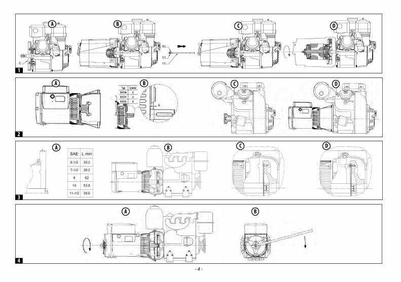
ISTRUZIONI PER IL MONTAGGIO Il montaggio deve essere effettuato da persone qualificate dopo la lettura del manuale.
FORMA COSTRUTTIVA B9 (ALTERNATORI SERIE SP-E1C)Tale forma costruttiva prevede l’accoppiamento diretto tra il motore primo e l’alternatore. Si consiglia di procedere all’assem-blaggio nel seguente modo:1) Fissare il coperchio “C” al motore primo come indicato nella figura 1A.2) Fissare l’alternatore al suo coperchio con i 4 bulloni previsti come indicato nella figura 1B.3) Applicare il tirante “13” per il fissaggio assiale del rotore, inserendo la rondella “50” , avvitando il dado autobloccante “51 “
e facendo uscire il tirante di circa 2mm , come indicato nella figura 1C.4) Bloccare assialmente il rotore serrando il tirante con chiave dinamometrica ( coppia di serraggio 21 Nm per tiranti M8 , 48
Nm per tiranti M10 e 120 Nm per tiranti M14 ) come indicato nella figura 1D.Verificare che il dado autobloccante “51” abbia una porzione filettata del tirante che entri nel rotore per-mettendo così un sicuro bloccaggio.
Inoltre prima del montaggio verificare che le sedi coniche d’accoppiamento (su alternatore e motore) siano regolari e ben pulite. Nel caso in cui vi sia prevista una bussola filettata di riduzione, deve essere avvitata sull’al-bero motore prima di tutto e poi si può procedere con i punti 1-2-3-4.
FORMA COSTRUTTIVA B3/B14 (ALTERNATORI SERIE E1C)La forma costruttiva B3/B14 obbliga all’uso di un giunto elastico tra motore primo e alternatore. Il giunto elastico non dovrà dare origine a forze assiali o radiali durante il funzionamento e dovrà essere montato rigidamente sulla sporgenza dell’albero dell’alternatore. Si consiglia di eseguire l’assemblaggio seguendo le seguenti fasi:1) Applicare sull’alternatore il semigiunto e la campana di allineamento come rappresentato nella figura 2A.
- 7 -
Ital
iano Nel posizionamento del semigiunto sull’alternatore tenere presente che il rotore, ad accoppiamento completato, deve
poter conservare la possibilità di dilatarsi assialmente verso il cuscinetto lato opposto accoppiamento; perché ciò sia possibile è necessario che a montaggio finito la sporgenza dell’albero sia posizionata rispetto alle lavorazioni del coperchio, come rappresentato nella figura 2B.
2) Applicare sulla parte rotante del motore diesel il relativo semi-giunto come indicato in figura 2C.3) Montare i tasselli elastici del giunto.4) Accoppiare l’alternatore al motore primo fissando con le apposite viti la campana di accoppiamento (vedi figura 2D).5) Fissare con adatti antivibranti l’insieme motore-alternatore alla base facendo attenzione che non si creino tensioni
tendenti a deformare il naturale allineamento delle due macchine.6) Osservare che il cuscinetto lato opposto accoppiamento dell’alternatore abbia il previsto spazio di dilatazione (minimo
2 mm) e sia precaricato dalla molla di precarico.
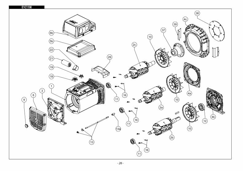
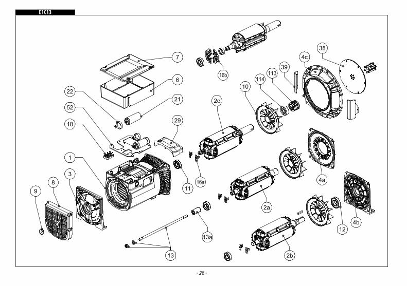
FORMA COSTRUTTIVA B2 (ALTERNATORI SERIE E1C11 - E1C13)Anche tale forma prevede l’accoppiamento diretto tra motore e alternatore. Si consiglia di procedere all’assemblaggio nel seguente modo:1) Controllare il corretto posizionamento del rotore con l’ausilio della tabella riportata in figura 3A.2) Togliere eventuali mezzi di bloccaggio del rotore posti sul lato opposto accoppiamento.3) Avvicinare l’alternatore al motore primo come rappresentato in figura 3B.4) Centrare e fissare lo statore alla flangia del motore primo con le apposite viti come indicato in figura 3C.5) Centrare e fissare con le apposite viti il giunto del rotore al volano del motore primo, agendo attraverso le aperture
apposite, come indicato in figura 3D.
Girare il rotore come indicato in figura 4A e B. Al termine dell’accoppiamento sopra descritto è necessario controllare il corretto posizionamento assiale; si deve cioè verificare che tra la fine del cuscinetto L.O.A. e la parete di bloccaggio assiale esista uno spazio di dilazione di 2 mm per la serie SP10 e E1C10, 3 mm per la serie E1C11 e E1C13.
UTILIZZO Le operazioni di collegamento dei cavi di potenza devono essere eseguite da personale qualificato con
macchina definitivamente ferma e scollegata elettricamente dal carico. Tensione e frequenza di erogazione: questi alternatori sono predisposti per erogare esclusivamente la
Funzionamento in ambienti particolari. Nel caso si usi l’alternatore in un gruppo insonorizzato fare attenzione che la sua aria aspirata sia sempre quella fresca in entrata; ciò si ottiene sistemandolo vicino alla presa d’aria con l’esterno. Inoltre bisogna tener conto che la quantità d’aria richiesta dall’alternatore è di:- SP10: 4 m3/min. - E1C10: 4 m3/min. - E1C11: 5 m3/min. - E1C13: 10 m3/min.
TARATURA DELLA TENSIONE E DELLA VELOCITÀ DI ROTAZIONELe operazioni di taratura devono essere eseguite esclusivamente da personale qualificato poiché c’è il pericolo di folgorazione.
Il controllo della tensione di uscita dell’alternatore deve essere effettuato alla velocità di rotazione nominale.
- 8 -
Leggeri scostamenti della tensione di uscita possono dipendere dal fatto che la velocità di rotazione è diversa da quella nominale. Considerare che la tensione di uscita varia in modo proporzionale al quadrato della variazione della velocità, nel caso si voglia, ad una determinata velocità, correggere la tensione di uscita è necessario (con alternatore fermo):a) aumentare la capacità del condensatore di eccitazione per aumentare la tensione;b) diminuire la capacità del condensatore di eccitazione per diminuire la tensione.
Circuito di carica batterieGli alternatori della serie SP10 e E1C/2 possono essere dotati di circuito carica batterie con possibilità di erogare una
corrente di eccitazione massima di 10 A. Il ponte raddrizzatore del carica batterie è normalmente previsto per 600 V. -10 A.
Eccitazione dell’alternatorePuò verificarsi, a seguito di uno smontaggio o per qualche raro inconveniente, che l’alternatore si disecciti; è allora
necessario provvedere alla sua eccitazione; dopo averlo regolarmente montato al motore primo, applicare ai morsetti di uscita in serie, per il solo tempo necessario all’eccitazione e con alternatore alla velocità nominale, una tensione a c.c. di 12V. A uno dei due conduttori che vanno dalle batterie ai morsetti di uscita, si consiglia un fusibile da 10 A- 250 V.
Controllo dei diodi rotantiIl sistema più idoneo a controllare lo stato dei diodi rotanti è quello con batteria e lampada perché non richiede che il diodo
sia scollegato dal suo avvolgimento. Si deve disporre di una batteria a 12 V. e di una lampada tipo «abbagliante» usata nei fari anteriori delle auto (potenza circa 50 W). Si dovranno eseguire i due collegamenti la lampada si dovrà accendere regolarmente solo quando il collegamento sia eseguito secondo la figura 8 (A: lampada accesa, B lampada spenta).CuscinettiI cuscinetti degli alternatori sono autolubrificati e quindi non richiedono manutenzioni per un periodo di funzionamento superiore alle 10000 ore. Quando si deve procedere alla revisione generale del gruppo elettrogeno è consigliabile lavare i cuscinetti con adatto solvente.
TIPI DI CUSCINETTO Alternatore Lato accoppiamento Lato opp. accoppiamento SP10 6204-2Z-C3 E1C10 6305-DDU-C3E 6204-2Z-C3 E1C11 6207-2Z-C3 6205-2Z-C3 E1C13 6208-2Z-C3 6305-DDU-C3E
INCONVENIENTE CAUSE INTERVENTI
Alternatore con tensione a vuoto bassa
1) Velocità di rotazione bassa 1) Portare alla velocità nominale
2) Diodo rotante guasto 2) Controllare e sostituire il diodo
3) Condensatore con capacità troppo bassa 3) Aumentare la capacità del condensatore
4) Guasto in un avvolgimento 4) Controllare la resistenza e sostituire la parte avariata
Tensione a vuoto alta
1) Condensatore con capacità troppo alta 1) Diminuire la capacità del condensatore
2) Velocità di rotazione troppo alta 2) Riportare il motore primo alla velocità nominale.
L’alternatore non si eccita
1) Velocità di rotazione bassa 1) Controllare n. giri, eventualmente portare a vel. corretta
2) Errore nei collegamenti 2) Controllare schema elettr. E ripristinare il corretto collegamento
3) Condensatore guasto 3) Sostituire il condensatore
4) Guasto negli avvolgimenti 4) Controllare resist. avvolgimenti e sostituire parte difettosa
5) Diodo rotante guasto 5) Controllare e sostituire il diodo
Tensione corretta a vuoto ma bassa a carico
1) Diodo rotante guasto 1) Controllare i diodi e sostituire quello guasto
2) Velocità di rotazione troppo bassa a carico 2) Correggere la taratura del regolatore di giri
3) Carico troppo elevato 3) Ridurre la corrente erogata
4) Cosф del carico troppo basso 4) Applicare un condensatore in parallelo all’utilizzatore con il Cosф più basso
Funzionamento rumoroso
1) Cattivo accoppiamento 1) Controllare e modificare l’allineamento
2) Presenza di un corto circuito negli avvolg. o nel carico
2) Controllare gli avvolgimenti e i carichi, quindi sostituire quello avariato
3) Cuscinetto difettoso 3) Sostituire il cuscinetto
Tensione instabile
1) Rotazione del motore irregolare 1) Controllare il motore primo ed intervenire
2) Contatto incerto nei collegamenti 2) Verificare e stringere i collegamenti incerti
3) Presenza di un carico irregolare 3) Controllare i carichi ed eliminare quello irregolare
- 9 -
PRECAUTIONSBefore operating the generating set read the «Operating and Maintenance Manual» both of the generating set and of the alternator, and follow the recommendations below:⇒ A safe and efficient working can be achieved only if the machines are used correctly, in compliance with the instructions
provided by the relevant operational and maintenance handbooks and safety regulations.⇒ An electric shock can cause serious personal injuries and even death.⇒ Do not remove the terminal box lid or the safety screens before the alternator has come to a complete stop and before
switching off the genset.⇒ Only competent and qualified personnel should carry out the maintenance of the generating set.⇒ Do not wear loose garments when working near the generating set. All persons operating, handling or servicing the genset must always wear protective gloves and safety footwear. In the
event that the alternator, or the whole generating set needs to be lifted from ground, the operators must also wear a safety helmet.
Safety warnings. Notice panels used in this manual have the following meaning:
IMPORTANT! refers to dangerous or risky operations that may cause damage to the product.CAUTION! refers to dangerous or risky operations that may damage the product or cause personal injury.
WARNING! refers to dangerous or risky operations that may cause serious personal injury or even death.
DANGER!: refers to an immediate risk that may cause serious personal injury or death.
The final installer of the generating set must make sure that all necessary safety arrangements are put in place in order to make the whole plant compliant with current local safety regulations (earthing, contact protection,
explosion and fire safety measures, emergency stop, etc.…)
ALTERNATOR DESCRIPTIONThe SP - E1C/2 - E1C/4 is a series of two-pole, four-pole, single-phase brushless alternators, equipped with an auxiliary winding (loaded on a capacitor) which ensures voltage regulation. They are produced in compliance with EN 60204-1, EN61000-6-2, EN61000-6-4, EN 55014-1, EN 55011 specifications, as well as with the directives No. 2006/95/CE, 2004/108/CE.Ventilation: Axial with air inlet from non-drive end sideEnclosure protection: Standard IP 21 (IP 23 on demand).Direction of rotation: Both directions are allowed. Electrical features: Insulation components are made of class H materials, both for the stator and for the rotor. Windings are tropicalized.Power values: They refer to the following conditions: ambient temperature up to 40°C, altitude up to 1000 m. above sea-level, continuous duty at P.F. = 1.
Overloads: 10% overload, lasting 1 hour, and occurring every 6 hours, is acceptable.Mechanical features: Frame, front cover and rear shield are made of a special aluminium alloy to better withstand vibrationsThe shaft is made of high-tensile steel. The rotor is particularly sturdy to withstand the drive engine escape velocity.It is equipped with a damping cage which allows satisfactory operation even with single-phase, distorted loads. Bearings are
sealed for life.Operation in particular settings: Should the alternator operate at more than 1,000 m above sea-level, a 4% derating every 500 m increase will need to be applied. Should the ambient temperature exceed 40°C a 4% derating every 5°C increase will need to be applied.
INSTALLATION AND START UP The following start up and control operations should be carried out by qualified personnel only.
⇒ The alternator must be installed in a well ventilated room. Room temperature should not exceed standard recommended values.
⇒ Particular attention must be paid to ensure that air inlets and outlets are never obstructed. While installing the alternator it is important to avoid direct suction of warm air coming from the alternator’s outlet and/or from the prime motor.
⇒ Before starting up the alternator it is advisable to check (visually and manually) that all terminals are properly clamped and that the rotation of the rotor in not blocked in any way.
If the alternator has not been used for a long time, before starting it up it is recommended to test the windings insulation resistance to earth, keeping into account that every single part has to be isolated from the others.
This particular checkup must be carried out using a “Megger” instrument at 500 Vdc. Normally, windings having resistance to earth ≥ 1 MΩ are considered sufficiently insulated. If windings resistance is
lower than 1 MΩ , insulation will have to be restored by drying the winding (using, for example, an oven at 60° - 80°C temperature, or having a correct amount of current obtained from an auxiliary source circulate through the wiring
It is also necessary to verify that the alternator’s metallic parts, and the genset mass are bonded to site earth and that the earth circuit satisfies any applicable legal requirements.
Mistakes or oversights concerning earthing may have fatal effects.
ASSEMBLING INSTRUCTIONSAssembling should be carried out by qualified personnel after reading the manual.
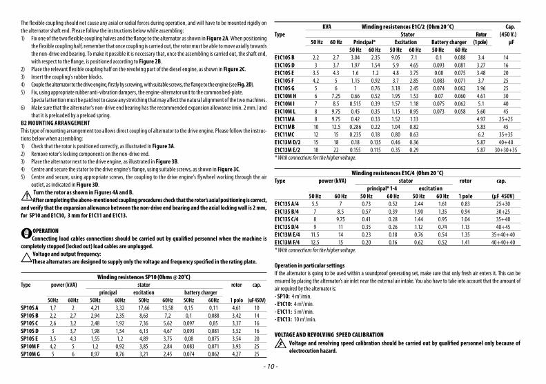
B9 MOUNTING ARRANGEMENT (ALTERNATORS SP-E1C SERIES)This type of mounting arrangement allows direct coupling between the first engine and the alternator. We recommend that you proceed with the assembly as follows:1) Secure the cover “C” to the engine as shown in Figure 1A.2) Secure the alternator to its cover with the 4 bolts provided as shown in Figure 1B.3) Apply the tie rod “13” for the axial securing of the rotor, inserting the washer “50”, screwing the self-locking nut “51” and
pulling out the tie rod about 2mm, as shown in Figure 1C.4) Axially lock the rotor by tightening the tie rod with a torque wrench (tightening torque OF 21 Nm for M8 tie rods, 48 Nm
for M10 and 120 Nm for M14 tie rods) as shown in Figure 1D.Check that the self-locking nut “51” has a threaded portion of the tie rod that enters the rotor thus allowing a secure locking.
Before assembly, check that the coupling conical seats (on the alternator and engine) are regular and clean. If there is a threaded reduction sleeve, it must be screwed onto the engine shaft and then proceed as shown in sections 1-2-3-4.
B3/B14 MOUNTING ARRANGEMENT (ALTERNATOR TYPE E1C)The B3/B14 mounting arrangement requires the use of a flexible coupling between the drive engine and the alternator.
Engl
ish
- 10 -
The flexible coupling should not cause any axial or radial forces during operation, and will have to be mounted rigidly on the alternator shaft end. Please follow the instructions below while assembling:1) Fix one of the two flexible coupling halves and the flange to the alternator as shown in Figure 2A. When positioning
the flexible coupling half, remember that once coupling is carried out, the rotor must be able to move axially towards the non-drive end bearing. To make it possible it is necessary that, once the assembling is carried out, the shaft end, with respect to the flange, is positioned according to Figure 2B.
2) Place the relevant flexible coupling half on the revolving part of the diesel engine, as shown in Figure 2C.3) Insert the coupling’s rubber blocks.4) Couple the alternator to the drive engine, firstly by screwing, with suitable screws, the flange to the engine (see Fig. 2D).5) Fix, using appropriate rubber anti-vibration dampers, the engine-alternator unit to the common bed-plate. Special attention must be paid not to cause any stretching that may affect the natural alignment of the two machines.6) Make sure that the alternator’s non-drive end bearing has the recommended expansion allowance (min. 2 mm.) and
that it is preloaded by a preload spring.B2 MOUNTING ARRANGEMENTThis type of mounting arrangement too allows direct coupling of alternator to the drive engine. Please follow the instruc-tions below when assembling:1) Check that the rotor is positioned correctly, as illustrated in Figure 3A.2) Remove rotor’s locking components on the non-drive end.3) Place the alternator next to the drive engine, as illustrated in Figure 3B.4) Centre and secure the stator to the drive engine’s flange, using suitable screws, as shown in Figure 3C.5) Centre and secure, using appropriate screws, the coupling to the drive engine’s flywheel working through the air
outlet, as indicated in Figure 3D.Turn the rotor as shown in Figures 4A and B.After completing the above-mentioned coupling procedures check that the rotor’s axial positioning is correct,
and verify that the expansion allowance between the non-drive end bearing and the axial locking wall is 2 mm, for SP10 and E1C10, 3 mm for E1C11 and E1C13.
OPERATIONConnecting load cables connections should be carried out by qualified personnel when the machine is
completely stopped (locked out) load cables are unplugged.Voltage and output frequency:These alternators are designed to supply only the voltage and frequency specified in the rating plate.
Operation in particular settingsIf the alternator is going to be used within a soundproof generating set, make sure that only fresh air enters it. This can be ensured by placing the alternator’s air inlet near the external air intake. You also have to take into account that the amount of air required by the alternator is:- SP10: 4 m3/min. - E1C10: 4 m3/min. - E1C11: 5 m3/min. - E1C13: 10 m3/min.
VOLTAGE AND REVOLVING SPEED CALIBRATIONVoltage and revolving speed calibration should be carried out by qualified personnel only because of electrocution hazard.
- 11 -
The alternator’s output voltage measurement should be carried out at the nominal revolving speed.Small deviations of the outlet voltage can depend on the fact that the revolving speed is different from the nominal one.Keep into account that the output voltage changes proportionally to the squared revolving speed variation, at nominal speed. If the output voltage needs to be adjusted, (with the alternator locked out) it will be necessary to:a) increase the capacitor’s excitation capacity to increase voltage;b) decrease the capacitor’s excitation capacity to decrease voltage.
Battery charger circuitThe SP10 and E1C/2 series alternators can be equipped with a battery charger circuit which supplies a maximum
current of 10 A. The rectifier bridge of the battery charger is usually selected for 600 V.-10 A.
Excitation of alternatorAs a result of disassembling operations, or because of some unusual failure, the alternator can loose its excitation. In such
a case, after it has been coupled to the drive engine, it is necessary to excite the alternator by applying a 12 Vdc voltage to the output terminals (only for the time necessary for the excitation and with the alternator set at nominal speed). It is advisable to connect a 10 A - 250 V fuse in series to one of the two wires going from the batteries to the output terminals.
Rotating rectifier assembly inspectionThe best way to check the rotating diodes is using a battery and a bulb so that the diode does not need to be disconnected
from its winding. Using a 12 V battery and a «driving beam» type bulb (about 50 W), you will need to arrange the two connections as shown below, and the bulb should light up smoothly when connected as illustrated in fig. 8 (A: lamp ON, B: lamp OUT).BearingsThe bearings of the alternators are self lubrificated therefore they do not require maintenance for a period of more than 10000 hours. Should you proceed with the overhaul of the genset, it is advisable washing the bearings with a suitable solvent.
BEARING TYPE Alternator Drive-end side Opposite drive-end side SP10 6204-2Z-C3 E1C10 6305-DDU-C3E 6204-2Z-C3 E1C11 6207-2Z-C3 6205-2Z-C3 E1C13 6208-2Z-C3 6305-DDU-C3E
FAULT CAUSE ACTION
Low voltage with no-load
1) Too low drive engine RPM 1) Reset nominal speed for drive engine
2) Low revolving speed at full load 2) Adjust governor control to nominal speed
3) Load is too high 3) Reduce current supplied
4) Load PF is too low 4) Wire a capacitor in parallel with the lowest PF load
Noisy working 1) Bad coupling 1) Check and correct coupling
2) Short circuit in windings or load 2) Check windings and loads, and change faulty ones
3) Faulty bearing 3) Replace faulty bearing
Unstable voltage 1) Uneven engine rotation 1) Check drive engine and fix
2) Poor contact within connections 2) Check and tighten faulty connections
3) Irregular load 3) Check loads and remove irregular one
Engl
ish
- 12 -
MEDIDAS DE SEGURIDADAntes de utilizar el grupo electrógeno es indispensable leer el manual de “ Uso y Manutención” del grupo electrógeno y del alternador, siguiendo las siguientes recomendaciones:⇒ Un funcionamiento seguro y eficiente se puede obtener solo si las máquinas son utilizadas en modo correcto, siguiendo
las indicaciones de los manuales de “Uso y Mantenimiento” y las normas relativas a la seguridad.⇒ Un choque eléctrico puede provocar graves daños, inclusive la muerte.⇒ Está prohibido quitar la tapa de las conexiones y las protecciones del alternador mientras el mismo se encuentre en
movimiento o antes de haber desactivado el sistema de arranque del grupo electrógeno .⇒ El mantenimiento del grupo deberá ser realizado exclusivamente por personal calificado o especializado.⇒ No trabajar con ropaje suelto en las cercanías del grupo electrógeno. Las personas encargadas a la movilización deberán usar en todo momento guantes y zapatos de trabajo. Cada vez que el
generador se deba alzar del suelo, las personas involucradas en dicha operación deberán usar cascos de protección. En este manual usaremos símbolos que tienen el siguiente significado:
IMPORTANTE! Se refiere a una operación riesgosa o peligrosa que puede provocar daños al producto.
PRECAUCIÓN! Se refiere a una operación riesgosa o peligrosa que puede provocar daños al producto y heridas a las personas.
ATENCIÓN! Se refiere a una operación riesgosa o peligrosa que puede provocar graves heridas o eventualmente la muerte.
PELIGRO!: Se refiere a un riesgo inmediato que puede provocar graves heridas o la muerte.
El instalador final del grupo electrógeno es responsable de la predisposición de todas las medidas necesarias para obtener la conformidad del sistema con las normas locales vigentes de seguridad (puesta a tierra, protección contra contactos directos e indirectos, explosión, incendio, parada de emergencia, etc.).
DESCRIPCION DEL ALTERNADORLos alternadores de la serie SP - E1C/2 - E1C/4 son generadores monofásicos, a dos o cuatro polos, sin escobillas y con bobinado auxiliar (cargado sobre un condensador) para la regulación de la tensión. Los mismos están construidos en conformidad con las normas EN 60034-1, EN 60204-1, EN 55014-1, EN 55011 y con las directivas 2006/95/CE, 2004/108/CE. Ventilación: Axial con aspiración desde el lado opuesto al acoplamiento.Protección: El grado de protección estándar es IP 21 (a pedido IP 23). Sentido de rotación: Son permitidos los dos sentidos de rotación. Características eléctricas: Los aislamientos son de clase H para el rotor y el estator. Los bobinados son tropicalizados. Potencias: Están siempre referidas a las siguientes condiciones: temperatura ambiente inferior a 40 °C, altitud inferior a los 1000 m sobre el nivel del mar (s.n.m), servicio continuo a cosφ= 1.
Sobrecargas. Se acepta una sobrecarga del 10% por 1 hora cada 6 horas.Características mecánicas. Carcasa y tapas en aleación de aluminio de alta resistencia a las vibraciones.Eje en acero de alta resistencia. Rotor robusto, apto para resistir la velocidad de escape del motor, posee además jaula de amortiguamiento que permite un buen funcionamiento de la máquina aun con cargas de alta distorsión.Rodamientos lubricados de por vida.Funcionamiento en ambientes particulares: Si el alternador tiene que funcionar a una altitud superior a los 1000 m s.n.m es necesario reducir la potencia de salida un 4% por cada 500 m de incremento. Cuando la temperatura ambiente es superior a
40 °C se debe reducir la potencia entregada por el alternador del 4% por cada 5°C de incremento.
PUESTA EN MARCHALas siguientes operaciones de control y puesta en marcha deberán ser realizadas solo por personal calificado.
⇒ El alternador deberá ser instalado en un local con posibilidad de intercambio de aire atmosférico para evitar que la temperatura ambiente supere los valores previstos por las normas.
⇒ Es necesario prestar atención de manera que las aberturas previstas para la aspiración y descarga del aire en el alternador no se encuentren nunca obstruidas. Es importante además que la posición del alternador evite la aspiración de su propia descarga de aire caliente o de aquella del motor primario.
⇒ Antes de la puesta en marcha es necesario controlar visualmente y manualmente que todas las conexiones se encuentren bien ajustadas, y que no exista ninguna oposición a la rotación del rotor. Cuando el alternador haya permanecido por largo tiempo inutilizado, antes de la puesta en marcha es necesario controlar la resistencia de aislamiento de masa de todos los bobinados, teniendo siempre presente que se debe probar cada bobinado singularmente aislado de los otros.
Dicho control se deberá realizar con un instrumento denominado Megger y a una tensión de medida de 500V c.c. Normalmente se considera suficiente un valor de resistencia con respecto a masa ≥ 1 MΩ.
Si el valor medido es inferior, será necesario restablecer el aislamiento secando el bobinado por medio de un horno a una temperatura de 60-80°C (o eventualmente haciendo circular un valor de corriente eléctrica obtenida por una fuente auxiliar). Es necesario además, que todas las partes metálicas del alternador y la masa del grupo completo estén conectadas al circuito de tierra en conformidad con las normas vigentes.
Errores u olvidos en la conexión de tierra pueden provocar consecuencias mortales.
INSTRUCCIONES PARA EL MONTAJEIl montaje debe ser realizado por personal calificado después de la lectura de este manual.
FORMA CONSTRUCTIVA B9 (ALTERNADORES DE LA SERIE SP-E1C)Esta forma constructiva prevee el acoplamiento directo entre el motor y el alternador. Le recomendamos que proceda con el montaje de la siguiente manera:1) Fije la cubierta “C” al motor como se muestra en la Figura 1A.2) Fije el alternador a su cubierta con los 4 tornillos provistos como se muestra en la Figura 1B.3) Aplique la varilla de unión “13” para asegurar axialmente el rotor, insertando la arandela “50”, atornillando la tuerca auto-
blocante “51” y extrayendo la varilla de unión aproximadamente de 2 mm, como se muestra en la Figura 1C.4) Bloquee el rotor axialmente con una llave dinamométrica (par de apriete DE 21 Nm para barras de acoplamiento M8, 48 Nm
para para barras de acoplamiento M10 y 120 Nm para barras de acoplamiento M14) como se muestra en la Figura 1D.Verifique que la tuerca autoblocante “51” tenga una porción roscada de la barra de acoplamiento que in-gresa al rotor, lo que permite un bloqueo seguro.
Antes del montaje, compruebe que los asientos cónicos del acoplamiento sean regulares y estén limpios. Si hay un manguito de reducción roscado, se debe atornillar al primer motor y luego proceder como se muestra en las secciones 1-2-3-4.FORMA CONSTRUCTIVA B3/B14 (ALTERNADORES SERIE E1C)Dicha forma constructiva necesita de una junta elástica entre motor primario y alternador. Esta junta no deberá producir fuerzas axiales ni radiales durante el funcionamiento, deberá montarse rígidamente sobre la parte saliente del eje del alternador. Se aconseja seguir las siguientes operaciones:1) Aplicar sobre el alternador la semi-junta y la campana de alineamiento como se muestra en la figura 2A.
B9 MOUNTING ARRANGEMENT (ALTERNATORS SP-E1C SERIES)This type of mounting arrangement allows ... Spagnolo pag.12FORMA CONSTRUCTIVA B9 (ALTERNADORES DE LA SERIE SP-E1C)Esta forma constructiva prevee el …
- 13 -
Espa
ñol
En el montaje de la semi-junta tener presente que el rotor, una vez terminado el acoplamiento, tiene que tener la posibilidad de dilatarse axialmente hacia el lado del cojinete opuesto al acoplamiento; para que esto sea posible es necesario que, a montaje terminado, la parte saliente del eje se encuentre en una posición como indicada en la figura 2B.
2) Aplicar en la parte rotativa del diesel a motor la respectiva semi-junta como se indica en la figura 2C.3) Montar las cuñas elásticas de la junta.4) Acoplar el alternador al motor primario fijando con los tornillos respectivos la campana de acoplamiento. (Ver figura
2D).5) Fijar con antivibrantes adecuados el conjunto motor-alternador a la base, con particular precaución de evitar tensiones
que tiendan a deformar el natural alineamiento de las dos máquinas.6) Observar que el cojinete del lado opuesto al acoplamiento del alternador tenga previsto un espacio de dilatación (mínimo
2 mm) y se encuentre cargado con el resorte de precarga.FORMA CONSTRUCTIVA B2 (ALTERNADORES SERIE E1C11 - E1C13)También esta forma constructiva prevee el acoplamiento directo entre motor y alternador. Se aconseja seguir las siguientes operaciones:1) Controlar la correcta posición del rotor con el auxilio de la tabla indicada en la figura 3A.2) Quitar eventuales sistemas de bloqueo del rotor que se encuentren en el lado opuesto al acoplamiento.3) Acercar el alternador al motor primario como indicado en la figura 3B.4) Centrar y fijar con los tornillos respectivos el estator del alternador a la campana del motor, fig. 3C.5) Centrar y fijar con los tornillos respectivos la junta a discos del rotor al volante del motor, utilizar para dicha operación
las aberturas de ventilación como se indica en la figura 3D.Girar el rotor tal como se muestra en las figuras 4A y B.Al finalizar todos los acoplamientos descriptos precedentemente, es necesario controlar el correcto
posicionamiento axial; se deberá verificar que: entre el final del cojinete L.O.A (lado opuesto acoplamiento) y el tope axial, exista una distancia de dilatación de 2 mm para la serie SP10 y E1C10, 3 mm para la serie E1C11 y E1C13.
UTILIZACIONLas operaciones de conexión de los cables de potencia deben ser realizadas por personal calificado, con la
máquina completamente detenida y desconectada de la carga. Tensión y frecuencia de salidaEstos alternadores son predispuestos para entregar exclusivamente la tensión y la frecuencia indicada en
la tarjeta de datos.Resistencia de los bobinados SP10 (Ohms @ 20°C)
Tipo potencia (kVA) estator rotor cond. principal excitación carga bateria 50Hz 60Hz 50Hz 60Hz 50Hz 60Hz 50Hz 60Hz 1 polo (uF 450V)SP10S A 1,7 2 4,21 3,32 17,66 13,58 0,15 0,11 4,61 10SP10S B 2,2 2,7 2,94 2,35 8,63 7,2 0,1 0,088 3,42 14SP10S C 2,6 3,2 2,48 1,92 7,36 5,62 0,097 0,85 3,37 16SP10S D 3 3,7 1,98 1,54 6,13 4,67 0,093 0,081 3,52 16SP10S E 3,5 4,3 1,55 1,2 4,89 3,75 0,08 0,075 3,54 20SP10M F 4,2 5 1,2 0,92 3,85 2,84 0,083 0,071 3,93 25SP10M G 5 6 0,97 0,76 3,21 2,45 0,074 0,062 4,27 25
Funcionamiento en ambientes particularesEn el caso que el alternador se utilice dentro de un grupo insonorizado, es necesario preveer siempre la aspiración de aire fresco entrante; esto se logra mediante la colocación de cerca de la entrada de aire con el exterior. También tienes que tener en cuenta que la cantidad de aire requerido por el alternador es:- SP10: 4 m3/min. - E1C10: 4 m3/min. - E1C11: 5 m3/min. - E1C13: 10 m3/min.
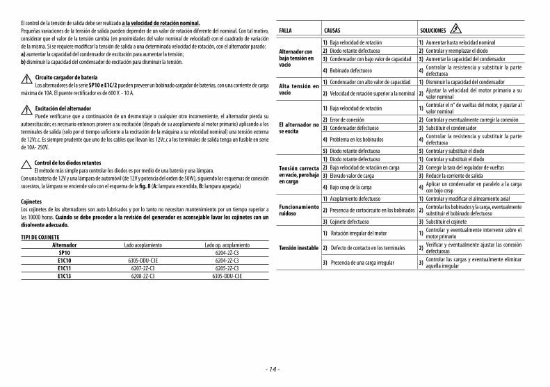
AJUSTE DE LA TENSION Y VELOCIDAD DE ROTACIONEstas operaciones de ajuste deben ser realizadas exclusivamente por personal calificado ya que existe un real peligro de electrocución.
- 14 -
El control de la tensión de salida debe ser realizado a la velocidad de rotación nominal.Pequeñas variaciones de la tensión de salida pueden depender de un valor de rotación diferente del nominal. Con tal motivo, considerar que el valor de la tensión cambia (en proximidades del valor nominal de velocidad) con el cuadrado de variación de la misma. Si se requiere modificar la tensión de salida a una determinada velocidad de rotación, con el alternador parado:a) aumentar la capacidad del condensador de excitación para aumentar la tensión;b) disminuir la capacidad del condensador de excitación para disminuir la tensión.
Circuito cargador de bateríaLos alternadores de la serie SP10 e E1C/2 pueden preveer un bobinado cargador de baterías, con una corriente de carga
máxima de 10A. El puente rectificador es de 600 V. - 10 A.
Excitación del alternadorPuede verificarse que a continuación de un desmontaje o cualquier otro inconveniente, el alternador pierda su
autoexcitación; es necesario entonces proveer a su excitación (después de su acoplamiento al motor primario) aplicando a los terminales de salida (solo por el tiempo suficiente a la excitación de la máquina a su velocidad nominal) una tensión externa de 12Vc.c. Es siempre prudente que uno de los cables que llevan los 12Vc.c a los terminales de salida tenga un fusible en serie de 10A- 250V.
Control de los diodos rotantesEl método más simple para controlar los diodos es por medio de una batería y una lámpara.
Con una batería de 12V y una lámpara de automóvil (de 12V y potencia del orden de 50W), siguiendo los esquemas de conexión sucesivos, la lámpara se enciende solo con el esquema de la fig. 8 (A: lampara encendida, B: lampara apagada)
CojinetesLos cojinetes de los alternadores son auto lubricados y por lo tanto no necesitan mantenimiento por un tiempo superior a las 10000 horas. Cuándo se debe proceder a la revisión del generador es aconsejable lavar los cojinetes con un disolvente adecuado.
TIPI DE COJINETE Alternador Lado acoplamiento Lado op. acoplamiento SP10 6204-2Z-C3 E1C10 6305-DDU-C3E 6204-2Z-C3 E1C11 6207-2Z-C3 6205-2Z-C3 E1C13 6208-2Z-C3 6305-DDU-C3E
FALLA CAUSAS SOLUCIONES
Alternador con baja tensión en vacío
1) Baja velocidad de rotación 1) Aumentar hasta velocidad nominal2) Diodo rotante defectuoso 2) Controlar y reemplazar el diodo3) Condensador con bajo valor de capacidad 3) Aumentar la capacidad del condensador
4) Bobinado defectuoso 4) Controlar la resistencia y substituir la parte defectuosa
Alta tensión en vacío
1) Condensador con alto valor de capacidad 1) Disminuir la capacidad del condensador
2) Velocidad de rotación superior a la nominal 2) Ajustar la velocidad del motor primario a su valor nominal
El alternador no se excita
1) Baja velocidad de rotación 1) Controlar el n° de vueltas del motor, y ajustar al valor nominal
2) Error de conexión 2) Controlar y eventualmente corregir la conexión3) Condensador defectuoso 3) Substituir el condensador
4) Problema en los bobinados 4) Controlar la resistencia y substituir la parte defectuosa
5) Diodo rotante defectuoso 5) Controlar y substituir el diodo
Tensión correcta en vacío, pero baja en carga
1) Diodo rotante defectuoso 1) Controlar y substituir el diodo2) Baja velocidad de rotación en carga 2) Corregir la tara del regulador de vueltas3) Elevado valor de carga 3) Reducir la corriente de salida
4) Bajo cosφ de la carga 4) Aplicar un condensador en paralelo a la carga con bajo cosφ
Funcionamiento ruidoso
1) Acoplamiento defectuoso 1) Controlar y modificar el alineamiento axial
2) Presencia de cortocircuito en los bobinados 2) Controlar los bobinados y la carga, eventualmente substituir el bobinado defectuoso
3) Cojinete defectuoso 3) Substituir el cojinete
Tensión inestable
1) Rotación irregular del motor 1) Controlar y eventualmente intervenir sobre el motor primario
2) Defecto de contacto en los terminales 2) Verificar y eventualmente ajustar las conexión defectuosas
3) Presencia de una carga irregular 3) Controlar las cargas y eventualmente eliminar aquella irregular
- 15 -
MESURES DE SECURITE Avant d’utiliser un groupe électrogène il faut lire la notice “d’emploi et entretien“ du groupe électrogène et de l’alternateur et suivre les instructions suivantes :⇒ On peut avoir un fonctionnement sûr et efficace seulement si les machines sont utilisées correctement, c’est a dire en
suivant les indications des notices d’emploi et d’entretien relatives.⇒ Une décharge électrique peut causer des dommages très graves ou la mort.⇒ Il est interdit d’enlever le capot de fermeture de la boîte à bornes et les protections de l’alternateur quand il est en
mouvement ou avant d’avoir désactivé le système de démarrage du groupe électrogène.⇒ L’entretien du groupe doit être effectué exclusivement par du personnel qualifié et spécialisé.⇒ Ne pas opérer avec des vêtements larges près du groupe électrogène. Le personnel préposé doit toujours porter les gants de travail et les chaussures de sécurité. Quand le générateur ou le
groupe complet doit être soulevé, les ouvriers doivent utiliser le casque de protection. Dans le présent manuel seront utilisés des symboles ayant le sens suivant:
IMPORTANT! se réfère à une opération risquée ou dangereuse qui peut endommager le produit.
PRUDENCE! se réfère à une opération risquée ou dangereuse qui peut endommager le produit ou blesser les personnes.
ATTENTION! se réfère à une opération risquée ou dangereuse qui peut causer de blessures très graves ou la mort.
DANGER! se réfère à une opération à risque immédiat qui pourrait causer de graves blessures ou la mort.
L’installateur du groupe électrogène est responsable de la prédisposition de toutes les mesures nécessaires afin que l’installation soit conforme aux normes locales de sécurité (mise à terre, protection contre le contact, protections contre explosion et incendie, arrêt d’urgence, etc)
DESCRIPTION DE L’ALTERNATEUR: Les alternateurs du type SP - E1C/2 - E1C/4 sont des générateurs monophasés, à deux ou quatre pôles, sans balais et avec bobinage auxiliaire (chargé sur le condensateur) qui assure la régulation de la tension et sont fabriqués en conformité aux normes EN 60204-1, EN61000-6-2, EN61000-6-4, EN 55014-1, EN 55011 et aux directives 2006/95/CE, 2004/108/CE.Ventilation: Axial avec l’aspiration du côté opposé à l’accouplement. Protection: Standard IP 21 (sur demande IP 23). Sens de rotation: Les deux sens de rotations sont possible.Caractéristiques électriques: Les isolations sont réalisés en Classe H aussi bien pour le stator que pour le rotor. Les bobinages sont tropicalisés. Puissances: Se réfèrent aux conditions suivantes: température ambiante maximum de 40°C, altitude maximum de 1000 m. au dessus du niveau de la mer , service continu à Cosф= 1.
Surcharges: L’alternateur peut accepter une surcharge du 10% pendant une heure toutes les 6 heures.Caractéristiques mécaniques: La carcasse et les couvercles sont en alliage d’aluminium qui résiste aux vibrations. L’axe est en acier à haute résistance. Le rotor est particulièrement robuste pour résister à la vitesse de fuite du moteur principal et avec une cage d’amortissement qui permet le bon fonctionnement aussi avec des charges monophasés déformantes. Les roulements sont lubrifiés à vie.Fonctionnement dans un milieu particulier. Si l’alternateur doit fonctionner à plus de 1000 m d’altitude il est nécessaire de réduire la puissance débitée de 4% chaque 500 mètres en plus. Si la température ambiante est supérieure à 40°C on doit réduire la puissance de 4% chaque 5°C en plus.
MISE EN SERVICELes opérations de contrôle pour la mise en service indiquées ci-après doivent être exécutées seulement par du personnel qualifié.
⇒ L’alternateur devra être monté dans un endroit aéré pour empêcher que la température ambiante dépasse les valeurs prévues dans les normes.
⇒ Il faut aussi faire attention que les orifices pour l’aspiration et l’échappement de l’air ne soient jamais bouchés et que l’alternateur soit monté de façon à éviter l’aspiration de l’air chaude émis par le alternateur même et/ou par le moteur principal.
⇒ Avant la mise en service il est nécessaire de contrôler visuellement et manuellement si toutes les bornes des différentes boites à bornes sont serrées correctement et qu’il n’existe aucun empêchement à la rotation du rotor. Si l’alternateur a demeuré longtemps inactif, avant de procéder à sa mise en route, contrôlez la résistance de l’isolation vers la masse des enroulements en considérant que toutes les parties à contrôler devront être isolées des autres.
Le contrôle doit être fait avec l’instrument à 500 V. courant continu nommé “Megger”. Normalement les enroulements avec une résistance vers la masse de ≥ 1 MΩ sont considérés comme suffisamment isolés. Si la valeur est inférieure il est nécessaire de remettre l’isolation en état et de les sécher (utilisant par exemple, un four à 60°-80°C, ou en y faisant circuler un courant électrique obtenu par une source auxiliaire).
Il est aussi nécessaire de vérifier que les parties métalliques de l’alternateur et la masse du groupe entier soient connectés au circuit de terre et que celui-ci répond aux normes de sécurité prévues par la loi.
Erreurs ou oublis de la mise à terre peuvent entraîner des conséquences même mortelles.
NOTICE DE MONTAGELe montage doit être effectué par du personnel qualifié et après la lecture de la notice.
FORME DE CONSTRUCTION B9 (ALTERNATEURS SÉRIE SP-E1C)Ce type de construction prévoit le couplage direct entre le moteur d’entraînement et l’alternateur. Il est recommandé de procéder à l’assemblage de la manière suivante :1) Fixer le capot “C” au moteur d’entraînement, comme l’indique la figure 1A.2) Fixer l’alternateur à son capot à l’aide des 4 boulons fournis, comme l’indique la figure 1B.3) Appliquer la bielle “13” pour la fixation axiale du rotor en insérant la rondelle “50”, en vissant l’écrou indesserrable “51“ et
en faisant sortir la bielle d’environ 2 mm, comme l’indique la figure 1C.4) Bloquer axialement le rotor en serrant la bielle à l’aide d’une clé dynamométrique (couple de serrage 21 Nm pour les
bielle M8 , 48 Nm pour les bielles M10 et 120 Nm pour les bielles M14), comme l’indique la figure 1D.Vérifier que l’écrou indesserrable “51” présente une partie filetée de la bielle qui pénètre dans le rotor, permettant ainsi un blocage sûr.
Par ailleurs, avant le montage, vérifier quel les emplacements coniques d’accouplement (sur l’alternateur et le moteur) sont réguliers et propres. Si un manchon de réduction fileté est prévu, il doit d’abord être vissé sur l’arbre du moteur et il sera ensuite possible de procéder aux points 1-2-3-4.
FORME B3/B14 (ALTERNATEUR E1C)Pour la forme de construction B3/B14 il faut utiliser un joint élastique entre le moteur principal et l’alternateur. Le joint élastique ne devra pas donner lieu à forces axiales ou radiales pendant le fonctionnent et doit être monté fermement sur le bout de l’arbre de l’alternateur. On conseille d’effectuer l’assemblage suivant les instructions ci-après: 1) Appliquez le demi-joint à l’alternateur et la cloche d’alignement comme indiqué sur la fig. 2A.
Fran
çais
- 16 -
En positionnant le demi-joint sur l’alternateur n’oubliez pas que le rotor, après le montage, doit avoir la possibilité de se dilater sur l’axe en direction du roulement côté opposé à l’accouplement.
Pour rendre possible cette opération il faut que, à montage terminé, le bout d’arbre soit positionné respect aux usinages du couvercle comme indiqué sur la fig. 2B.
2) Mettez sur la partie tournante du moteur diesel le demi-joint approprié comme indiqué sur la fig. 2C.3) Montez les bouchons élastiques du joint.4) Couplez l’alternateur au moteur principal en fixant la cloche d’alignement avec les vis appropriées (voir fig. 2D).5) Fixez avec des amortisseurs appropriés l’ensemble moteur-alternateur au socle en faisant attention de ne pas créer des
tensions qui peuvent déformer l’alignement naturel des 2 machines.6) Contrôler s’il y a une distance suffisante pour la dilatation du roulement du côté opposé à l’accouplement (minimum 2 mm)
et qu’il soit prechargé par le ressort de precharge.
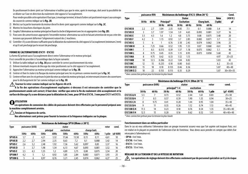
FORME B2 (ALTERNATEURS E1C11 - E1C13)La forme B2 prévoit aussi l’accouplement direct entre l’alternateur et le moteur principal.Il est conseillé de procéder à l’assemblage dans la façon suivante:1) Utiliser la table indiqué sur la fig. 3A pour contrôler le correct positionnement du rotor.2) Enlever éventuels moyens de blocage du rotor positionnés sur le côté opposé à l’accouplement.3) Approcher l’alternateur au moteur principal comme indiqué sur la fig. 3B.4) Centrer et fixer le stator à la flasque du moteur principal avec les vis prévues comme montré par la fig. 3C.5) Centrer et fixer avec les vis prévues le joint du rotor au volant du moteur principal, en intervenant à travers des ouvertures
pour le déchargement de l’air comme indiqué sur la fig. 3D.Tourner le rotor comme indiqué sur les figures 4A et B.A la fin des opérations d’accouplement expliquées ci-dessous il est nécessaire de contrôler que le
positionnement axiale soit correct; il faut donc vérifier que entre la fin du roulement côté accouplement et la surface de blocage il y a une distance pour la dilatation de 2 mm, pour SP10 et E1C10, 3 mm pour E1C11 et E1C13.
UTILISATIONLes opérations de connexion des câbles de puissance doivent être effectuées par le personnel préposé avec
la machine complètement arretée.Tension et fréquence de sortie.Nos alternateurs sont prévus pour fournir la tension et la fréquence indiquées sur la plaque.
Fonctionnement dans un milieu particulierDans le cas où vous utiliseriez l’alternateur dans un groupe insonorisé assurez-vous que l’air aspirée soit toujours frais; ceci est réalisé en le plaçant en proximité de l’admission d’air de l’extérieur. Vous devez aussi prendre en compte que debit d’air nécessaire à l’alternateur est:- SP10: 4 m3/min. - E1C10: 4 m3/min. - E1C11: 5 m3/min. - E1C13: 10 m3/min.
RÉGLAGE DE LA TENSION ET DE LA VITESSE DE ROTATIONLes opérations de réglage doivent être effectuées seulement par du personnel spécialisé car il y à le risque
- 17 -
d’électrocution.Le contrôle de la tension de sortie de l’alternateur doit être effectué à la vitesse de rotation nominale.Petits écarts dans la tension de sortie peuvent être causés par le fait que la vitesse de rotation est différente de celle nominale. Il faut donc considérer que la tension de sortie est variable proportionnellement au carré de la variation de la vitesse ; dans le cas où, à une certaine vitesse, on veut corriger la tension de sortie il faut suivre les indications suivantes après avoir arrêté l’alternateur:a) Augmenter la capacité du condensateur d’excitation pour augmenter la tension.b) Diminuer la capacité du condensateur d’excitation pour diminuer la tension.
Circuit de charge batterieSur les alternateurs de la série SP10 et E1C/2 on peut ajouter un circuit pour charger les batteries qui donne la
possibilité d’alimenter un courant d’excitation maximum de 10 A. Le pont à diode du circuit charge-batterie est normalement prévu pour 600 V - 10 A.
Excitation de l’alternateurAprès le démontage ou à cause d’un rare inconvénient, il est possible que l’alternateur se désexcite; dans ce cas il faut
l’exciter (après l’avoir régulièrement accouplé au moteur thermique) en applicant aux bornes de sortie une tension de 12 V c.c. pendant le temps nécessaire à l’excitation avec l’alternateur à la vitesse nominale. C’est conseillé de connecter en série un fusible de 10 A - 250 V. à l’ un de deux conducteurs placés entre les batteries et les bornes de sortie.
Contrôle des diodes tournantesLe système le meilleur pour contrôler l’état des diodes tournantes c’est avec une ampoule et une batterie, car il n’est pas
nécessaire de débrancher le pont à diodes de son bobinage. Il faut utiliser une batterie à 12 V. et une ampoule comme celle des pleins phares des voitures (puissance d’environ 50 W). Les deux branchements doivent être effectués comme indiqué ci-après et l’ampoule devrait s’allumer régulièrement seulement quand le branchement est effectué comme indiqué dans la fig. 8 (A: ampoule allumée, B: lampe éteinte).RoulementsLes roulements de l’alternateur sont graissés à vie, donc l’entretien n’est pas nécessaire pendant une période de plus de 10000 heurs. Lorsque d’un entretien du générateur il est conseillé de nettoyer les roulements avec un solvant approprié.
TYPE DE ROULEMENT Alternateur Côté accouplement Opposé à l’accouplement SP10 6204-2Z-C3 E1C10 6305-DDU-C3E 6204-2Z-C3 E1C11 6207-2Z-C3 36205-2Z-C3 E1C13 6208-2Z-C3 6305-DDU-C3E
DEFAUT CAUSE DU DEFAUT OPERATION A EFFECTUER
Tension à vide
basse
1) Vitesse d’entraînement trop faible 1) Remmener à la vitesse nominale2) Défaut du pont à diodes 2) Contrôler et remplacer la diode3) Condensateur avec une capacité insuffisante 3) Augmenter la capacité du condensateur
4) Défaut d’un bobinage 4) Contrôler la résistance et remplacer la pièce
détérioréeTension à vide
élevée
1) Condensateur avec capacité trop élevée 1) Réduire la capacité du condensateur2) Vitesse de rotation trop élevée 2) Régler le moteur thermique à la vitesse nominale
L’alternateur ne
s’excite pas
1) Vitesse de rotation insuffisante 1)Contrôler la vitesse de rotation et régler à la
vitesse correcte
2) Erreur de branchement 2)Contrôler le schéma électrique et réparer le
branchement 3) Défaut du condensateur 3) Remplacer le condensateur
4) Défaut des bobinages 4)Contrôler la résistance des bobinages et remplacer
la pièce défectueuse5) Panne sur diodes tournantes 5) Contrôler et remplacer les diodes
Tension correcte
à vide mais basse
en charge
1) Panne sur diodes tournantes 1) Contrôler et remplacer les diodes2) Vitesse de rotation trop basse en charge 2) Calibrer le régulateur de vitesse3) Charge trop élevée 3) Réduire le courant de sortie
4) Cosф de la charge trop bas 4)Brancher un condensateur en parallèle à la charge
avec cosφ le plus bas
Fonctionnement
bruyant
1) Faux couplage 1) Contrôler et modifier l’alignement
2) Court-circuit sur le bobinage ou sur la charge 2)Contrôler les bobinages et les charges et remplacer
la pièce défectueuse3) Roulement défectueux 3) Remplacer le roulement
Tension instable 1) Rotation du moteur irrégulier 1) Contrôler le moteur thermique et intervenir2) Mauvais contact des connexions 2) Vérifier et refaire les mauvais connexions3) Présence d’une charge irrégulière 3) Contrôler les charges et éliminer celles irrégulières
Fran
çais
- 18 -
SICHERHEITSMAßNAHMENVor dem Gebrauch des Stromaggregats ist es unerlässlich, das Benutzerhandbuch “Gebrauch und Wartung ” des Stromaggregats durchzulesen und folgende Empfehlungen zu berücksichtigen:⇒ Ein sicherer und effizienter Betrieb ist nur dann gewährleistet, wenn die Maschinen gemäß den Bestimmungen der
entsprechenden Handbücher “Gebrauch und Wartung” und der Sicherheitsnormen korrekt verwendet werden.⇒ Ein elektrischer Stromschlag kann zu schweren Schäden oder sogar zum Tod führen.⇒ Es ist verboten, die Verschlusskappe des Klemmengehäuses und die Schutzgitter des Generators anzunehmen, solange
dieser in Bewegung ist und solange nicht das Startsystem des Stromaggregats deaktiviert wurde.⇒ Die Wartung des Aggregats darf ausschließlich von qualifiziertem Fachpersonal durchgeführt werden.⇒ Sich nicht mit “offener” Kleidung in der Nähe des Stromaggregats aufhalten. Die für die Beförderung zuständigen Personen
müssen stets Arbeitshandschuhe und Unfallverhütungsschuhe tragen. Sollte der Generator oder das gesamte Aggregat vom Boden angehoben werden, müssen die Arbeiter einen Schutzhelm tragen.
In vorliegendem Handbuch werden Symbole mit folgenden Bedeutungen verwendet:
WICHTIG!: bezieht sich auf eine riskante oder gefährliche Operation, die Schäden Am Produkt verursachen kann.
VORSICHT!: bezieht sich auf eine riskante oder gefährliche Operation, die das Produkt beschädigen oder Verletzungen an Personen verursachen kann.
ACHTUNG! bezieht sich auf eine riskante oder gefährliche Operation, die zu schweren Verletzungen oder eventuell zum Tod führen kann.
GEFAHR!: bezieht sich auf ein unmittelbares Risiko, das zu schweren Verletzungen oder sogar zum Tod führen kann.
Der Endinstallateur des Stromaggregats ist verantwortlich alle Maßnahmen zu treffen, um die gesamte Anlage mit den geltenden lokalen Sicherheitsnormen konform zu machen (Erdung, Kontaktschutzvorrichtungen, Explosions- und Brandverhütungsvorrichtungen, Notstop, usw.).
BESCHREIBUNG DES GENERATORSBei den Generatoren der Serie SP - E1C/2 - E1C/4 handelt es sich zweipolige oder vierpolige Einphasengeräte ohne Bürsten mit Hilfswicklung (auf einen Kondensator geladen), zur Ermöglichung einer Spannungsregulierung, die gemäß den Normen EN 60204-1, EN61000-6-2, EN61000-6-4, EN 55014-1, EN 55011 und nach den Richtlinien 2006/95/CE, 2004/108/CE gebaut. Belüftung: Axial mit Ansaugen von der gegenüberliegenden Kupplungsseite. Schutz: Standard IP 21 (auf Anfrage IP 23). Drehrichtung: Beide Drehrichtungen sind erlaubt.Elektrische eigenschaften: Die Isolierungen wurden mit Materialien der Klasse H sowohl am Stator als auch am Rotor hergestellt. Die Wicklungen wurden tropenfest gemacht.Leistungen: Diese beziehen sich auf folgende Bedingungen: Raumtemperatur nicht über 40°C, Höhe nicht über 1000m ü.d.M., Dauerbetrieb bei Cosф= 1.
Überlast: Allgemein ist eine Überlast von 10% über 1 Stunde alle 6 Stunden zugelassen.Mechanische eigenschaften: Gehäuse und Abdeckungen sind aus vibrationsbeständiger Aluminiumlegierung hergestellt. Die Welle ist aus hochwiderstandsfähigem Stahl. Der Rotor ist besonders robust, um der Schleuderdrehzahl der Zugmotoren standzuhalten und ist mit einem Dämpfkäfig ausgestattet, der einen einwandfreien Betrieb auch bei verzerrenden Einphasenladungen erlaubt. Die Lager sind lebenslänglich geschmiert.Betrieb in besonderen umgebungen: Wenn der Generator in einer Meereshöhe über 1000m betrieben werden soll, ist eine
Verringerung der erbrachten Leistung von 4% pro 500 Meter Höhenanstieg notwendig. Wenn die Umgebungstemperatur über 40° C liegt, ist die erbrachte Leistung des Generators um 4% pro 5° C Anstieg notwendig.INBETRIEBNAHME
Folgende Operationen zur Kontrolle und Inbetriebnahme dürfen nur von qualifiziertem Fachpersonal ausgeführt werden.
⇒ Der Generator ist in einem Raum zu installieren, der die Möglichkeit eines Luftaustauschs mit der Atmosphäre bietet, um zu verhindern, dass die Umgebungstemperatur die von den Normen vorgesehenen Werte übersteigt.
⇒ Darauf achten, dass die zum Ansaugen vorgesehenen Öffnungen und der Luftabzug zu keinem Zeitpunkt verstopft sind und dass die für das Aufstellen des Generators verwendete Technik ein direktes Ansaugen der vom selben Generator und/oder Hauptmotor abgegebenen heißen Luft verhindert.
⇒ Vor der Inbetriebnahme ist es notwendig, mittels Sicht- und manueller Kontrolle aller Klemmen der verschiedenen Klemmenbretter deren einwandfreien Sitz und das behinderungsfreie Rotieren des Motors sicherzustellen. Sollte der Generator über längere Zeit nicht in Betrieb sein, ist vor der erneuten Inbetriebnahme der Isolierwiderstand gegen die Masse der Wicklungen zu kontrollieren, wobei darauf zu achten ist, dass jedes einzelne zu kontrollierende Teil von den anderen abisoliert sein muss. Diese Kontrolle ist mit einem 500 V. c.c. Gerät durchzuführen, das Megger genannt wird. Normalerweise werden diejenigen Wicklungen als ausreichend isoliert betrachtet, die einen Widerstandswert gegen die Masse von ≥ 1 MΩ besitzen. Sollte der gemessene Wert geringer sein, ist eine Wiederherstellung des Widerstandes durch Trocknen der Wicklung vorzunehmen, z.B. durch Verwendung eines Ofens bei 60-80°C (oder indem man in diesem einen geeigneten Stromwert von einer Hilfsstromquelle fließen lässt.). Es ist notwendig, zu prüfen, dass die metallischen Teile des Generators und die Masse des gesamten Aggregats an den Erdungskreislauf angeschlossen sind und dass letzterer den gesetzlich vorgeschriebenen Bestimmungen entspricht.
Fehler oder Nachlässigkeiten bei der Erdung können tödliche Folgen haben.
MONTAGEANLEITUNG Die Montage ist von qualifiziertem Fachpersonal nach Lesen des Handbuchs durchzuführen.
BAUFORM B9 (DREHSTROMGENERATOREN REIHE SP-E1C)Diese Bauform sieht die direkte Verbindung zwischen dem Motor und dem Drehstromgenerator vor. Es wird empfohlen, wie folgt mit der Montage fortzufahren:1) Befestigen Sie die Abdeckung “C” am Antriebsmotor, wie in der Abbildung 1A dargestellt.2) Befestigen Sie den Drehstromgenerator an seiner Abdeckung mit den 4 vorgesehenen Schrauben, wie in der Abbildung
1B dargestellt.3) Bringen Sie die Zugstange “13” für die axiale Befestigung des Rotors an, indem Sie die Unterlegscheibe “50” einsetzen und
die selbstsichernde Mutter “51” festschrauben und die Zugstange etwa 2mm austreten lassen, wie in der Abbildung 1C gezeigt.
4) Blockieren Sie den Rotor axial, indem Sie die Zugstange mit dem Drehmomentschlüssel festziehen (Anzugsdrehmoment 21 Nm für Zugstangen M8, 48 Nm für Zugstangen M10 und 120 Nm für Zugstangen M14), wie in der Abbildung 1D gezeigt.
Stellen Sie sicher, dass die selbstsichernde Mutter “51” einen Gewindeabschnitt der Zugstange hat, der in den Rotor eintritt, um so eine sichere Blockierung zu ermöglichen.
Prüfen Sie zudem vor der Montage, ob die konischen Kupplungssitze (auf Drehstromgenerator und Motor) gleichmäßig und gut gesäubert sind. Falls eine Reduzierhülse mit Gewinde vorgesehen ist, muss sie zuerst auf die Motorwelle geschraubt werden. Anschließend kann man mit den Punkten 1-2-3-4 fortfahren.
- 19 -
FÜR DIE BAUART B3/B14 (GENERATOR E1C)Die Bauart B3/B14 erfordert die Verwendung eines elastischen Verbindungsstücks zwischen Hauptmotor und Generator. Das elastische Verbindungsstück entwickelt während des Betriebs axiale oder radiale Kräfte und wird steif an den Vorsprung der Welle des Generators montiert. Es empfiehlt sich beim Zusammenbau in folgenden Phasen vorzugehen:1) Das Halbverbindungsstück und die Ausrichtglocke am Generator wie in Abb. 2A anbringen. Beim Positionieren des Halbverbindungsstücks am Generator beachten, dass der Rotor bei komplettem Kuppeln die
Möglichkeit beibehalten muss, sich axial in Richtung des Lagers der Kupplung der gegenüberliegenden Seite ausdehnen zu können; um dies zu ermöglichen, ist es notwendig, dass nach Beendigung der Montage der Vorsprung der Welle hinsichtlich der Verarbeitung der Abdeckung wie in der Abbildung und in der entsprechenden Abb. 2B positioniert wird.
2) Am rotierenden Teil des Dieselmotors das entsprechende Halbverbindungsstück wie in Abb. 2C anbringen.3) Die elastischen Dübel des Verbindungsstücks anbringen.4) Den Generator an den Hauptmotor kuppeln, indem man mit den entsprechenden Schrauben die Kupplungsglocke befestigt
(siehe Abb. 2D).5) Mit geeigneten Vibrationsschutzvorrichtungen die Gesamtheit aus Motor und Generator an der Basis befestigen und darauf
achten, dass keine Spannungen entstehen, welche tendenziell die natürliche Ausrichtung der beiden Maschinen deformieren.6) Darauf achten, dass das Lager der gegenüberliegenden Kupplungsseite den vorgesehenen Ausdehnungsraum (Minimum
2 mm) besitzt und durch die Vorspannfeder vorgespannt ist.HINSICHTLICH DER FORM B2 (GENERATOREN E1C11-E1C13)Auch diese Form sieht eine direkte Kupplung zwischen Motor und Generator vor. Es empfiehlt sich beim Zusammenbau wie folgt vorzugehen:1) Die korrekte Positionierung des Rotors mit Hilfe der in Abb. 3A aufgeführten Tabelle kontrollieren.2) Eventuelle Blockiervorrichtungen des Rotors an der gegenüberliegenden Kupplungsseite entfernen.3) Den Generator an den Hauptmotor wie in Abb. 3B annähern.4) Den Stator zentrieren und an den Flansch des Hauptmotors mit den entsprechenden Schrauben wie in Abb. 3C befestigen.5) Mit den entsprechenden Schrauben das Verbindungsstück des Rotors zentrieren und am Schwungrad des Hauptmotors
befestigen, indem den Zugang über die Luftabflussöffnungen benutzt, siehe Abb. 3D.
Drehen Sie den Rotor, wie in den Figuren 4A und B gezeigtAm Ende aller oben beschriebenen Kupplungsinstallierungen ist es notwendig, die korrekte axiale Positionierung zu kontrollieren; d.h. es ist sicherzustellen, dass zwischen dem Ende des Lagers L.O.A. und der Wand der axialen Blockierung folgender Ausdehnungsraum vorhanden ist 2 mm für SP10 und E1C10, 3 mm für E1C11 und E1C13.
ANSCHLUSSDie Anschlussoperationen der Kraftstromkabel sind von Fachpersonal bei tatsächlich stehender und elektrisch
von der Ladung getrennter Maschine durchzuführen.Entwickelte Spannung und Frequenz: Diese Generatoren sind voreingestellt, um ausschließlich die auf dem Datenschild angegebene Spannung und Frequenz zu entwickeln.
Betrieb in besonderen umgebungenSollte man den Generator in einem schalldichten Aggregat verwenden, ist darauf zu achten, dass dessen angesaugte Luft stets die am Eingang angesaugte Frischluft ist; dies erhält man dadurch, dass man diesen in der Nähe von Luftöffnungen aufstellt, die nach außen gehen. Außerdem ist darauf zu achten, dass die vom Generator benötigte Luftmenge wie folgt ist:- SP10: 4 m3/min. - E1C10: 4 m3/min. - E1C11: 5 m3/min. - E1C13: 10 m3/min. D
euts
ch
- 20 -
STÖRUNG URSACHE EINGRIFFE
Generator mit geringer Leerspannung
1) Niedrige Rotationsgeschwindigkeit 1) Auf Nenngeschwindigkeit bringen
2) Rotierende Diode schadhaft 2) Diode kontrollieren und austauschen
3) Kondensator mit zu geringer Kapazität 3) Kondensatorkapazität erhöhen
4) Schadung an einer Wicklung 4) Widerstand kontrollieren u. schadhaftes Teil austauschen
Hohe Leerspannung
1) Kondensator mit zu hoher Kapazität 1) Kondensatorkapazität verringern
2) Rotationsgeschwindigkeit zu hoch 2) Hauptmotor wieder auf Nenngeschwindigkeit bringen.
4) Schaden an den Wicklungen 4) Wicklungswiderstand kontroll. u. schadh. Teil austauschen
5) Rotierende Diode schadhaft 5) Diode kontrollieren und austauschen
Korrekte Leerspannung aber geringe Ladespannung
1) Rotierende Diode schadhaft 1) Dioden kontrollieren und beschädigte austauschen
2) Rotationsgeschwindigkeit zu gering unter Belastung 2) Eichung des Drehzahlreglers korrigieren
3) Zu hohe Ladung 3) Abgegebenen Strom verringern
4) Leistungsfaktor der Ladung zu gering 4) Kondensator parallel zum Anschluss einbauen mit dem niedrigsten Leistungsfaktor Cosф
Geräuschbildung bei Betrieb
1) Schlechte Kupplung 1) Ausrichtung kontrollieren und ändern
2) Vorliegen eines Kurzschl. i. d. Wicklungen o. i. d. Ladg. 2) Wickl. und Ladungen kontrollieren, dann austauschen
3) Lager schadhaft 3) Lager auswechseln
Instabile Spannung
1) Unregelmäßige Motorrotation 1) Hauptmotor kontrollieren und reparieren
2) Unsicherer Kontakt a. d. Anschlüssen 2) Unsichere Anschlüsse finden und festziehen
3) Vorliegen einer unregelmäßigen Ladung 3) Ladungen kontrollieren und unregelmäßige entfernen.
EICHUNG DER SPANNUNG UND DER ROTATIONSGESCHWINDIGKEITDie Eichungsoperationen dürfen ausschließlich von qualifiziertem Fachpersonal durchgeführt werden, da Stromschlaggefahr besteht.
Die Ausgangsspannungskontrolle des Generators muss bei Nennrotationsgeschwindigkeit durchgeführt werden. Leichte Abweichungen von der Ausgangsspannung können davon abhängen, dass sich die Rotationsgeschwindigkeit vom Nennwert unterscheidet. Man beachte, dass die Ausgangsspannung (im Bereich der Nennrotationsgeschwindigkeit) Variationen unterliegt, die zum Quadrat der Geschwindigkeitsvariation proportional sind. Wenn man bei einer bestimmten Geschwindigkeit die Ausgangsspannung korrigieren möchte, dann ist (bei stehendem Generator) wie folgt vorzugehen:a) die Kapazität des Erregungskondensators erhöhen, um die Spannung zu erhöhen;b) die Kapazität des Erregungskondensators verringern, um die Spannung zu verringern.
BatterieladeschaltkrteisDie Generatoren der Serie SP10 und E1C/2 sind mit einem Batterieladeschaltkreis erhältlich, der in der Lage ist, einen
maximalen Erregungsstrom von 10 A zu entwickeln. Die Gleichrichterbrücke des Batterieladers ist normalerweise für 600 V. -10 A vorgesehen.
Erregung des generatorsEs kann vorkommen, dass der Generator nach dem Abbauen oder aufgrund irgendeiner seltenen Störung seine Erregung
verliert; in diesem Fall ist es notwendig, diesen wieder zu erregen (nachdem man diesen regulär an den Hauptmotor montiert hat), indem an die Klemmen 1 und 4 (nur während der zur Erregung notwendigen Zeit und bei Generator auf Nenngeschwindigkeit) eine Spannung von a c.c. 12V anschließt. An einen der beiden Leiter, die von den Batterien an die Klemmen 1 und 4 führen, sollte man eine Sicherung von 10 A- 250 V einbauen.
Kontrollen der rotierenden diodenDas zum Kontrollieren des Zustands der rotierenden Dioden am geeignetste System besteht aus einer Batterie und einer
Glühbirne, da es nicht erforderlich ist, die Diode von Ihrer Wicklung abzutrennen. Man muss daher über eine 12V-Batterie und eine Glühbirne vom Typ „Fernlicht“ verfügen, die als vordere Lichter bei Autos verwendet werden (Leistung ca. 50 W). Sie werden die Durchführung der beiden Links haben Sie, um die Lampe regelmäßig nur dann, wenn die Verbindung hergestellt drehen, wie in Abbildung 8 dargestellt (A: Lampe die, B: Lampe aus ).LagerDie Lager der Drehstromgeneratoren sind selbstschmierend und benötigen deshalb keinerlei Wartung für eine Betriebsdauer von über 10000 Stunden. Wann sollte man mit der Überholung des Generators gehen ist es ratsam, die Lager mit einem geeigneten Lösungsmittel zu waschen.LAGERTYP Generator Seitigen Kupplung Nicht Kupplung SP10 6204-2Z-C3 E1C10 6305-DDU-C3E 6204-2Z-C3 E1C11 6207-2Z-C3 6205-2Z-C3 E1C13 6208-2Z-C3 6305-DDU-C3E
- 21 -
PARTI DI RICAMBIO SPARE PARTS LISTA DE REPUESTOS PIECES DETACHEES ERSATZTEILE
- 22 -
SP 10
- 23 -
SP10S - SP10M
* Specificare codice dell’alternatore e data di produzione* Specifiy alternator’s type and date of production* Precisar modelo del alternador y fecha de producción* Préciser type de l’alternateur et date de production* Geben Sie den Code der generator und das Herstellungsdatum
Nº RICAMBI PARE PARTS LISTA DE REPUESTOS PIECES DETACHEES ERSATZTEILE
1a CARCASSA «S» CON STATORE «S» FRAME WITH STATOR CARCASA «S» CON ESTATOR CARCASSE «S» AVEC STATOR GEHÄUSE «S» MIT STATOR
1b CARCASSA «M» CON STATORE «M» FRAME WITH STATOR CARCASA «M» CON ESTATOR CARCASSE «M» AVEC STATOR GEHÄUSE «M» MIT STATOR
22 FASCIA CONDENSATORE CAPACITOR CLAMP ANILLA CONDENSADOR COLLIER CONDENSATEUR KLEMMSCHALTUNG
- 24 -
E1C10S - E1C10M
- 25 -
E1C10S - E1C10M
* Specificare codice dell’alternatore e data di produzione* Specifiy alternator’s type and date of production* Precisar modelo del alternador y fecha de producción* Préciser type de l’alternateur et date de production* Geben Sie den Code der generator und das Herstellungsdatum
Nº RICAMBI SPARE PARTS LISTA DE REPUESTOS PIECES DETACHEES ERSATZTEILE
1a CARCASSA «S» CON STATORE «S» FRAME WITH STATOR CARCASA «S» CON ESTATOR CARCASSE «S» AVEC STATOR GEHÄUSE «S» MIT STATOR
1b CARCASSA «M» CON STATORE «M» FRAME WITH STATOR CARCASA «M» CON ESTATOR CARCASSE «M» AVEC STATOR GEHÄUSE «M» MIT STATOR
29a PROTEZIONE IP21 CASSA “S” IP 21 COVER SHORT FRAME “S” PROTECCION IP 21 CARCASA “S” PROTECTION IP 21 CARCASSE “S” SCHUTZ IP 21 GEHÄUSE “S”
29b PROTEZIONE IP21 CASSA “S” IP 21 COVER SHORT FRAME “S” PROTECCION IP 21 CARCASA “S” PROTECTION IP 21 CARCASSE “S” SCHUTZ IP 21 GEHÄUSE “S”
- 26 -
E1C11M
- 27 -
E1C11M
* Specificare codice dell’alternatore e data di produzione* Specifiy alternator’s type and date of production* Precisar modelo del alternador y fecha de producción* Préciser type de l’alternateur et date de production* Geben Sie den Code der generator und das Herstellungsdatum
Nº RICAMBI SPARE PARTS LISTA DE REPUESTOS PIECES DETACHEES ERSATZTEILE
1 CARCASSA CON STATORE FRAME WITH STATOR CARCASA CON ESTATOR CARCASSE AVEC STATOR GEHÄUSE MIT STATOR
39 PROTEZIONE SCUDO MD35 MD 35 FRONT COVER PROTECTION PROTECCION TAPA DELANTERA MD35 PROTECTION FLASQUE AVANT MD35 SCHUTZ FÜR ZUBEHÖR
- 28 -
E1C13
- 29 -
E1C13
* Specificare codice dell’alternatore e data di produzione. - Specifiy alternator’s type and date of production. - Precisar modelo del alternador y fecha de producción. - Préciser type de l’alternateur et date de production. - Geben Sie den Code der generator und das Herstellungsdatum
Nº RICAMBI SPARE PARTS LISTA DE REPUESTOS PIECES DETACHEES ERSATZTEILE
1 CARCASSA CON STATORE FRAME WITH STATOR CARCASA CON ESTATOR CARCASSE AVEC STATOR GEHÄUSE MIT STATOR