92
Power Power Factor Factor Correction Correction

Power Power Factor Factor
CorrectionCorrection
Power Factor CorrectionPower Factor Correction
Power Factor:Power Factor:
Power Factor is a measure of how Power Factor is a measure of how efficiently electrical power is efficiently electrical power is consumedconsumed
Power Factor CorrectionPower Factor Correction
The The power factorpower factor of an AC electric power of an AC electric power system is defined as the ratio of the real power system is defined as the ratio of the real power to the apparent power, and is a number to the apparent power, and is a number between 0 and 1.between 0 and 1.
Power Factor CorrectionPower Factor Correction
Real Power and Apparent Power:Real Power and Apparent Power:
Real power is the capacity of the circuit for Real power is the capacity of the circuit for performing work in a particular time. Apparent performing work in a particular time. Apparent power is the product of the current and voltage power is the product of the current and voltage of the circuit.of the circuit.
Power Factor CorrectionPower Factor Correction
Real Power and Apparent Power:Real Power and Apparent Power:
In alternating current circuits, voltage and In alternating current circuits, voltage and current only remain in phase if the load is current only remain in phase if the load is purely resistive. When this happens the power purely resistive. When this happens the power is said to be 'real power'.is said to be 'real power'.
Power Factor CorrectionPower Factor Correction
Real Power and Apparent Power:Real Power and Apparent Power:
If instead the load is purely reactive (either If instead the load is purely reactive (either Capacitive or Inductive), all of the power is reflected Capacitive or Inductive), all of the power is reflected back to the generator. The load is said to draw zero back to the generator. The load is said to draw zero real power, instead it draws only 'reactive power'. If a real power, instead it draws only 'reactive power'. If a load is both resistive and reactive, its will have both load is both resistive and reactive, its will have both real and reactive power, resulting in total amount of real and reactive power, resulting in total amount of power called the 'apparent power'. power called the 'apparent power'.
Power Factor CorrectionPower Factor Correction
Real Power and Apparent Power:Real Power and Apparent Power:
In AC power systems, attached loads that In AC power systems, attached loads that store energy behave like combinations of coils store energy behave like combinations of coils (inductors) and capacitors. Coils store power (inductors) and capacitors. Coils store power as magnetic fields and cause delay changes in as magnetic fields and cause delay changes in the current (current lags). Capacitors store the current (current lags). Capacitors store power as electric charge, and therefore cause power as electric charge, and therefore cause advance changes in currents (current leads).advance changes in currents (current leads).
Power Factor CorrectionPower Factor Correction
Real Power and Apparent Power:Real Power and Apparent Power:
The portion of power flow averaged over a The portion of power flow averaged over a complete cycle of the AC waveform that complete cycle of the AC waveform that results in net transfer of energy in results in net transfer of energy in one one directiondirection is known as real power. The portion is known as real power. The portion of power flow due to stored energy which of power flow due to stored energy which returns to the sourcereturns to the source in each cycle is known as in each cycle is known as reactive power.reactive power.
Power Factor CorrectionPower Factor Correction
Real Power and Apparent Power:Real Power and Apparent Power:
In reality there are losses along AC power In reality there are losses along AC power transmission lines, due to a purely reactive transmission lines, due to a purely reactive load, which draws no real power itself, and load, which draws no real power itself, and consumes power because the supplied and consumes power because the supplied and reflected power dissipate away on the reflected power dissipate away on the transmission line, and energy is wasted. transmission line, and energy is wasted.
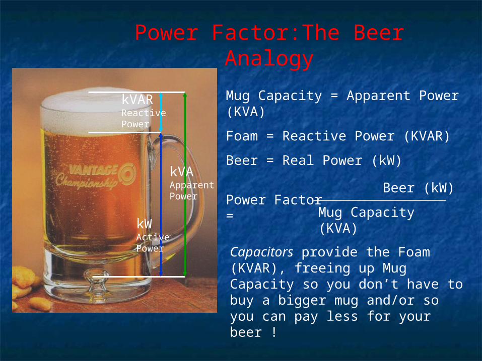
Power Factor:The Beer Analogy
Mug Capacity = Apparent Power (KVA)
Foam = Reactive Power (KVAR)
Beer = Real Power (kW)
Power Factor =
Beer (kW)
Mug Capacity (KVA)
Capacitors provide the Foam (KVAR), freeing up Mug Capacity so you don’t have to buy a bigger mug and/or so you can pay less for your beer !
kVARReactivePower
kWActivePower
kVAApparentPower
Power Factor CorrectionPower Factor Correction
For this reason an AC For this reason an AC load should be load should be
designed to have as designed to have as little reactive power little reactive power
as possible.as possible.
Power Factor CorrectionPower Factor Correction
Real Power and Apparent Power:Real Power and Apparent Power:
The following terms are used to describe energy The following terms are used to describe energy flow in a System. Each of them is assigned with a flow in a System. Each of them is assigned with a different unit to differentiate between them):different unit to differentiate between them):
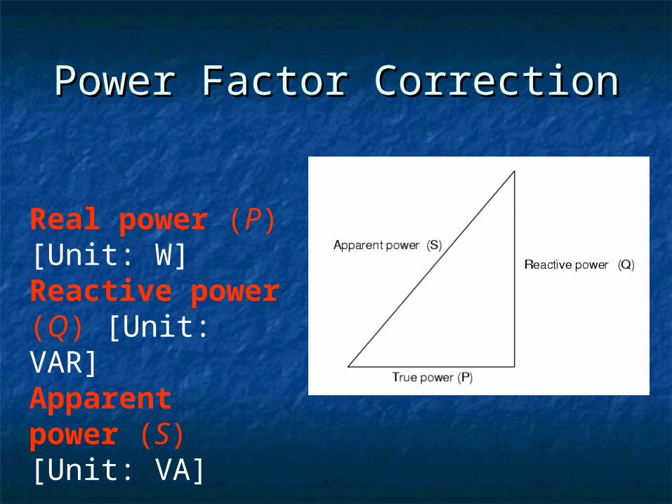
Power Factor CorrectionPower Factor Correction
Real power (P) [Unit: W] Reactive power (Q) [Unit: VAR] Apparent power (S)[Unit: VA]
Power Factor CorrectionPower Factor Correction
Real Power and Apparent Power:Real Power and Apparent Power:The unit for all forms of power is the watt (symbol: The unit for all forms of power is the watt (symbol: W). However, this unit is generally reserved for the W). However, this unit is generally reserved for the real power component. Apparent power is real power component. Apparent power is conventionally expressed in conventionally expressed in volt-amperesvolt-amperes (VA) since (VA) since it is the simple product of rms voltage and rms it is the simple product of rms voltage and rms current. The unit for reactive power is given the current. The unit for reactive power is given the special name "VAR", which stands for volt-amperes special name "VAR", which stands for volt-amperes reactive (since reactive power flow transfers no net reactive (since reactive power flow transfers no net energy to the load, it is sometimes called "wattless" energy to the load, it is sometimes called "wattless" power). power).
Power Factor CorrectionPower Factor Correction
Significance of the Power FactorSignificance of the Power FactorConsider an ideal alternating current (AC) circuit Consider an ideal alternating current (AC) circuit consisting of a source and a generalized load, where consisting of a source and a generalized load, where both the current and voltage are sinusoidal. If the load both the current and voltage are sinusoidal. If the load is purely resistive, the two quantities reverse their is purely resistive, the two quantities reverse their polarity at the same time, the direction of energy flow polarity at the same time, the direction of energy flow does not reverse, and only real power flows. If the does not reverse, and only real power flows. If the load is purely reactive, then the voltage and current load is purely reactive, then the voltage and current are 90 degrees out of phase and there is no net power are 90 degrees out of phase and there is no net power flow. This energy flowing backwards and forwards is flow. This energy flowing backwards and forwards is known as reactive power.known as reactive power.
Power Factor CorrectionPower Factor Correction
If a capacitor and an inductor are placed in If a capacitor and an inductor are placed in parallel, then the currents flowing through the parallel, then the currents flowing through the inductor and the capacitor oppose and tend to inductor and the capacitor oppose and tend to cancel out rather than adding. Conventionally, cancel out rather than adding. Conventionally, capacitors are considered to generate reactive capacitors are considered to generate reactive power and inductors to consume it. power and inductors to consume it.
Power Factor CorrectionPower Factor Correction
In a purely resistive AC circuit, voltage and current In a purely resistive AC circuit, voltage and current waveforms are in phase, changing polarity at the waveforms are in phase, changing polarity at the same instant in each cycle. Where reactive loads are same instant in each cycle. Where reactive loads are present, such as with capacitors or inductors, energy present, such as with capacitors or inductors, energy storage in the loads result in a time difference storage in the loads result in a time difference between the current and voltage waveforms. This between the current and voltage waveforms. This stored energy returns to the source and is not stored energy returns to the source and is not available to do work at the load. Thus, a circuit with a available to do work at the load. Thus, a circuit with a low power factor will have higher currents to transfer low power factor will have higher currents to transfer a given quantity of real power than a circuit with a a given quantity of real power than a circuit with a high power factor.high power factor.
Power Factor CorrectionPower Factor Correction
Circuits containing purely resistive heating Circuits containing purely resistive heating elements (filament lamps, heaters, cooking elements (filament lamps, heaters, cooking stoves, etc.) have a power factor of 1.0. stoves, etc.) have a power factor of 1.0. Circuits containing inductive or capacitive Circuits containing inductive or capacitive elements (lamp , motors, etc.) often have a elements (lamp , motors, etc.) often have a power factor below 1.0. power factor below 1.0.
Power Factor CorrectionPower Factor Correction
The significance of power factor lies in the The significance of power factor lies in the fact that utility companies supply customers fact that utility companies supply customers with volt-amperes, but bill them for watts. with volt-amperes, but bill them for watts. Power factors below 1.0 require a utility to Power factors below 1.0 require a utility to generate more than the minimum volt-amperes generate more than the minimum volt-amperes necessary to supply the real power (watts). necessary to supply the real power (watts). This increases generation and transmission This increases generation and transmission costs.costs.
An Example to understand the An Example to understand the Power FactorPower Factor
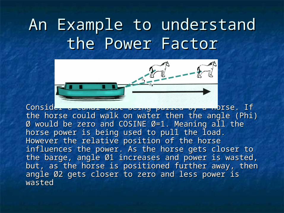
Consider a canal boat being pulled by a horse. If the Consider a canal boat being pulled by a horse. If the horse could walk on water then the angle (Phi) Ø would horse could walk on water then the angle (Phi) Ø would be zero and COSINE Ø=1. Meaning all the horse power be zero and COSINE Ø=1. Meaning all the horse power is being used to pull the load. is being used to pull the load. However the relative position of the horse influences However the relative position of the horse influences the power. As the horse gets closer to the barge, angle the power. As the horse gets closer to the barge, angle Ø1 increases and power is wasted, but, as the horse is Ø1 increases and power is wasted, but, as the horse is positioned further away, then angle Ø2 gets closer to positioned further away, then angle Ø2 gets closer to zero and less power is wasted zero and less power is wasted
Power Factor CorrectionPower Factor Correction
Much of the discussion is Much of the discussion is made about Power Factor. made about Power Factor. Now we switch towards the Now we switch towards the means and ways to solve means and ways to solve
the problem low power the problem low power factor.factor.
Power Factor CorrectionPower Factor Correction
Power factor correctionPower factor correction (PFC) is the process (PFC) is the process of adjusting the characteristics of electric loads of adjusting the characteristics of electric loads that create a power factor that is less than 1.that create a power factor that is less than 1.
Power Factor CorrectionPower Factor Correction
Power factor correction may be applied either by an Power factor correction may be applied either by an electrical power transmission utility to improve the electrical power transmission utility to improve the stability and efficiency of the transmission network; stability and efficiency of the transmission network; or, correction may be installed by individual electrical or, correction may be installed by individual electrical customers to reduce the costs charged to them by customers to reduce the costs charged to them by their electricity supplier. A high power factor is their electricity supplier. A high power factor is generally desirable in a transmission system to reduce generally desirable in a transmission system to reduce transmission losses and improve voltage regulation at transmission losses and improve voltage regulation at the load. the load.
Power Factor CorrectionPower Factor Correction
Why Power Factor Correction?Why Power Factor Correction?The current through the reactive component (IThe current through the reactive component (I reactivereactive) ) dissipates no power, and neither does it register on dissipates no power, and neither does it register on the watt hour meter. However, the reactive current the watt hour meter. However, the reactive current does dissipate power when flowing through other does dissipate power when flowing through other resistive components in the system, like the wires, the resistive components in the system, like the wires, the switches, and the lossy part of a transformer (Rswitches, and the lossy part of a transformer (R lineline). ). Switches have to interrupt the total current, not just Switches have to interrupt the total current, not just the active component. Wires have to be big enough to the active component. Wires have to be big enough to carry the entire current, etc. Therefore Correcting the carry the entire current, etc. Therefore Correcting the power factor reduces the amount of oversizing power factor reduces the amount of oversizing necessary. necessary.
Power Factor CorrectionPower Factor Correction
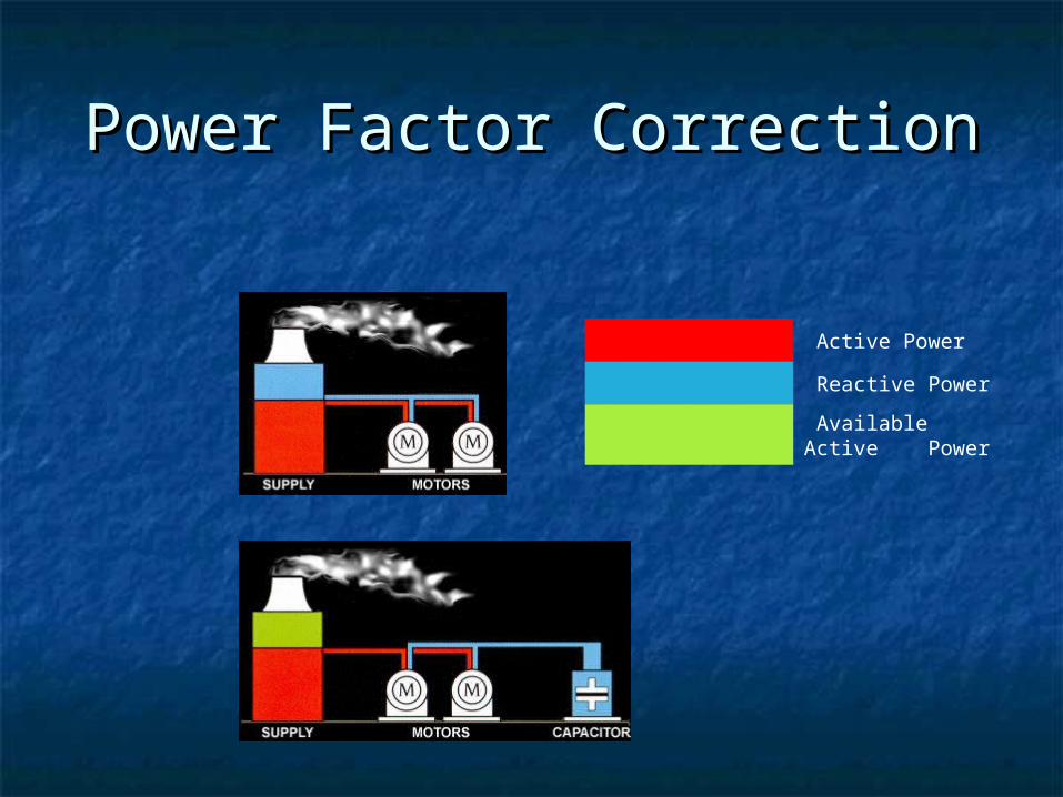
The introduction of Power Factor The introduction of Power Factor Correction Correction capacitorscapacitors is a widely is a widely recognized method of reducing an recognized method of reducing an electrical load, thus minimizing electrical load, thus minimizing wasted energy and hence improving wasted energy and hence improving the efficiency of a plant and reducing the efficiency of a plant and reducing the electricity bill.the electricity bill.
Power Factor CorrectionPower Factor Correction
Active Power
Reactive Power
Available Active Power
Power Factor CorrectionPower Factor Correction
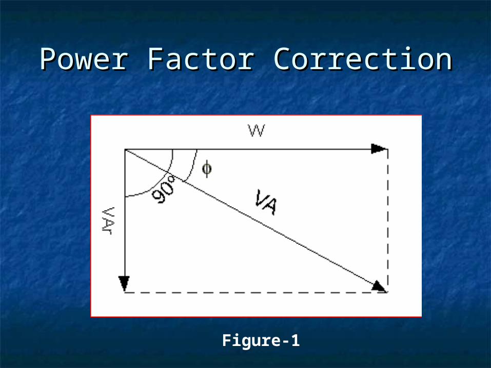
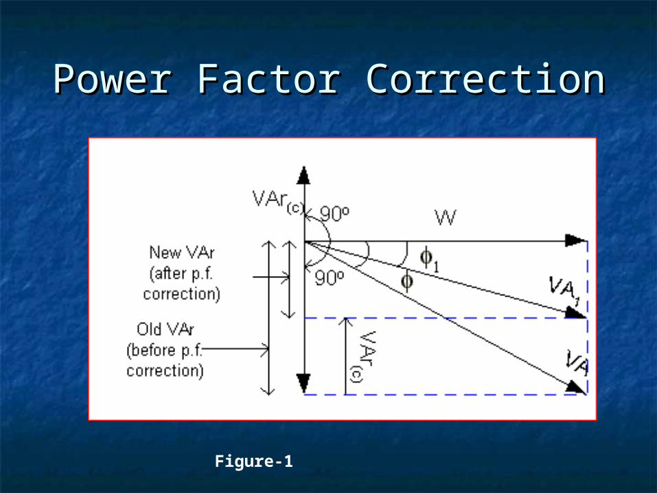
The inductive components, draw Reactive The inductive components, draw Reactive Power (VAr) from the mains. It lags behind Power (VAr) from the mains. It lags behind the Active Power (W) by 90the Active Power (W) by 90oo (Figure 1). A (Figure 1). A capacitor, if connected across the mains, will capacitor, if connected across the mains, will also draw Reactive Power [VAr(c)], but it also draw Reactive Power [VAr(c)], but it leadsleads the Active Power (W) by 90 the Active Power (W) by 90oo. The . The direction of the direction of the capacitivecapacitive Reactive Power Reactive Power [VAr(c)] is opposite to the direction of the [VAr(c)] is opposite to the direction of the inductive Reactive Power (VAr) (Figure 2). inductive Reactive Power (VAr) (Figure 2).
Power Factor CorrectionPower Factor Correction
Figure-1
Power Factor CorrectionPower Factor Correction
Figure-1
Power Factor CorrectionPower Factor Correction
The power factor can also be improved by The power factor can also be improved by synchronous Motors.synchronous Motors. These machines draw leading These machines draw leading kVAR when they are over-excited and, especially kVAR when they are over-excited and, especially when they are running idle. They are employed for when they are running idle. They are employed for correcting the power factor in bulk and have the correcting the power factor in bulk and have the special advantage that the amount of correction can special advantage that the amount of correction can be varied by changing their excitation.be varied by changing their excitation.
Power Factor CorrectionPower Factor Correction
The reactive power drawn by the synchronous The reactive power drawn by the synchronous motor is a function of its field excitation. It is motor is a function of its field excitation. It is started and connected to the electrical network. started and connected to the electrical network. It operates at full leading power factor and It operates at full leading power factor and puts VARs onto the network . Its principal puts VARs onto the network . Its principal advantage is the ease with which the amount advantage is the ease with which the amount of correction can be adjusted; it behaves like of correction can be adjusted; it behaves like an electrically variable capacitor.an electrically variable capacitor.Phase advancerPhase advancer can also be used. They are can also be used. They are fitted with individual machines.fitted with individual machines.
Power Factor CorrectionPower Factor Correction
Most loads on an electrical distribution system fall into one of Most loads on an electrical distribution system fall into one of three categories; resistive, inductive or Capacitive.The most three categories; resistive, inductive or Capacitive.The most common is inductive load. Typical examples of this include common is inductive load. Typical examples of this include transformers, fluorescent lighting and AC induction motors. transformers, fluorescent lighting and AC induction motors. Most inductive loads use a conductive coil winding to produce Most inductive loads use a conductive coil winding to produce an electromagnetic field, allowing the motor to function. All an electromagnetic field, allowing the motor to function. All inductive loads require two kinds of power to operate:inductive loads require two kinds of power to operate:Active power Active power (kwatts) - to produce the motive force (kwatts) - to produce the motive force Reactive powerReactive power (kvar) - to energise the magnetic field (kvar) - to energise the magnetic field The operating power from the distribution system is composed The operating power from the distribution system is composed of both active (working) and reactive (non-working) elements. of both active (working) and reactive (non-working) elements. The active power does useful work in driving the motor The active power does useful work in driving the motor whereas the reactive power only provides the magnetic field.whereas the reactive power only provides the magnetic field.
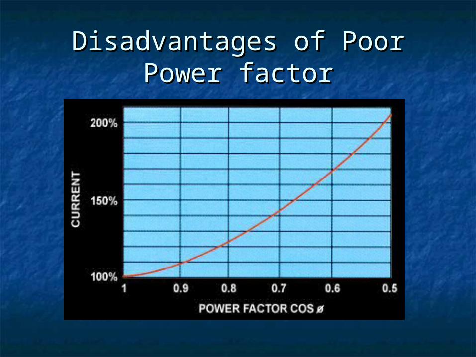
Disadvantages of Poor Power Disadvantages of Poor Power factorfactor
As the power factor drops the system becomes less efficient. A As the power factor drops the system becomes less efficient. A drop from 1.0 to 0.9 results in 15% more current being drop from 1.0 to 0.9 results in 15% more current being required for the same load.A power factor of 0.7 requires required for the same load.A power factor of 0.7 requires approximately 43% more current; and a power factor of 0.5 approximately 43% more current; and a power factor of 0.5 requires approximately 100% (twice as much) to handle the requires approximately 100% (twice as much) to handle the same load.same load.
The objective, therefore, should be to reduce the The objective, therefore, should be to reduce the reactive power drawn from the supply by improving the power reactive power drawn from the supply by improving the power factor. If an AC motor were 100% efficient it would consume factor. If an AC motor were 100% efficient it would consume only active power but, since most motors are only 75% to 80% only active power but, since most motors are only 75% to 80% efficient, they operate at a low power factor. This means poor efficient, they operate at a low power factor. This means poor energy and cost efficiency because the Regional Electricity energy and cost efficiency because the Regional Electricity Companies charge you at penalty rates for a poor power Companies charge you at penalty rates for a poor power factor.factor.
Disadvantages of Poor Power Disadvantages of Poor Power factorfactor
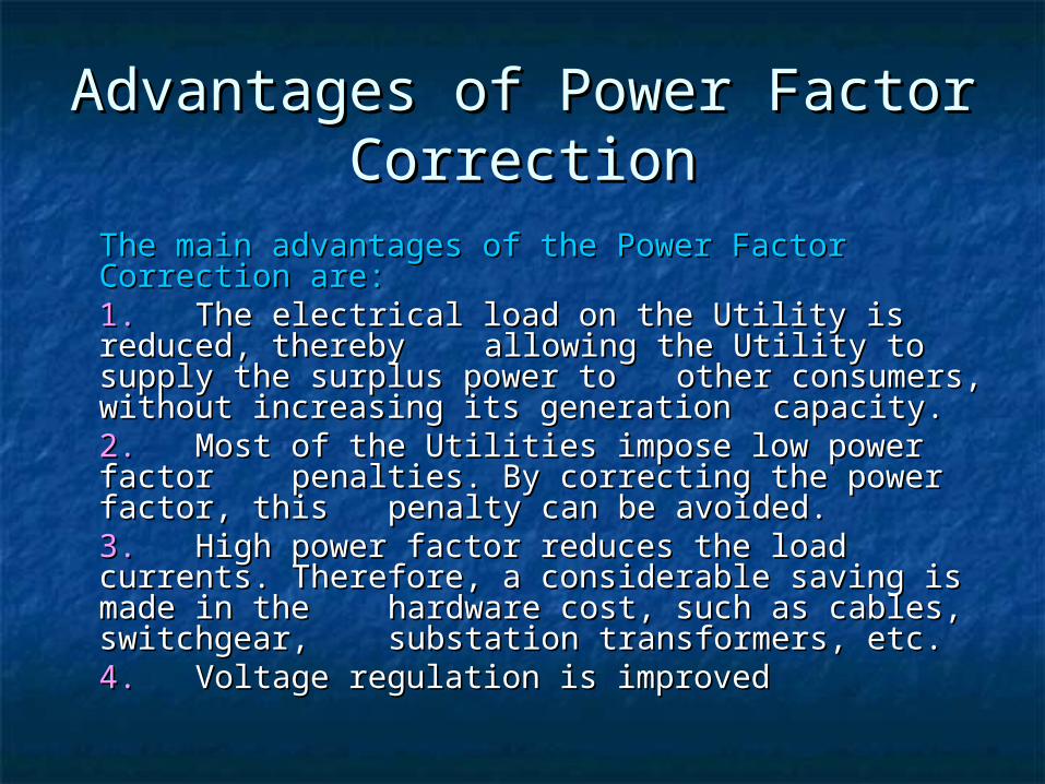
Advantages of Power Factor Advantages of Power Factor CorrectionCorrection
The main advantages of the Power Factor The main advantages of the Power Factor Correction are:Correction are:1.1. The electrical load on the Utility is reduced, The electrical load on the Utility is reduced, thereby thereby allowing the Utility to supply the allowing the Utility to supply the surplus power to surplus power to other consumers, without other consumers, without increasing its generation increasing its generation capacity.capacity.2.2. Most of the Utilities impose low power Most of the Utilities impose low power factor factor penalties. By correcting the power penalties. By correcting the power factor, this factor, this penalty can be avoided.penalty can be avoided.3.3. High power factor reduces the load High power factor reduces the load currents. currents. Therefore, a considerable saving is Therefore, a considerable saving is made in the made in the hardware cost, such as cables, hardware cost, such as cables, switchgear, switchgear, substation transformers, etc.substation transformers, etc.4. 4. Voltage regulation is improvedVoltage regulation is improved
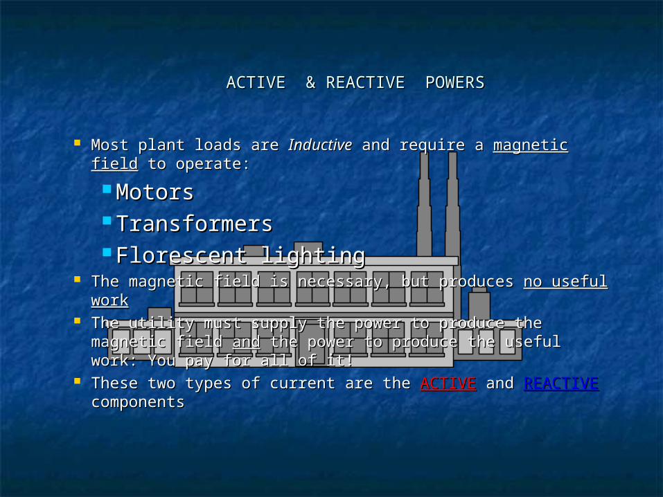
Most plant loads are Most plant loads are InductiveInductive and require a and require a magnetic fieldmagnetic field to operate:to operate:
MotorsMotors TransformersTransformers Florescent lightingFlorescent lighting
The magnetic field is necessary, but produces The magnetic field is necessary, but produces no useful workno useful work The utility must supply the power to produce the magnetic The utility must supply the power to produce the magnetic
field field andand the power to produce the useful work: You pay for the power to produce the useful work: You pay for all of it!all of it!
These two types of current are the These two types of current are the ACTIVEACTIVE and and REACTIVEREACTIVE componentscomponents
ACTIVE & REACTIVE POWERSACTIVE & REACTIVE POWERS
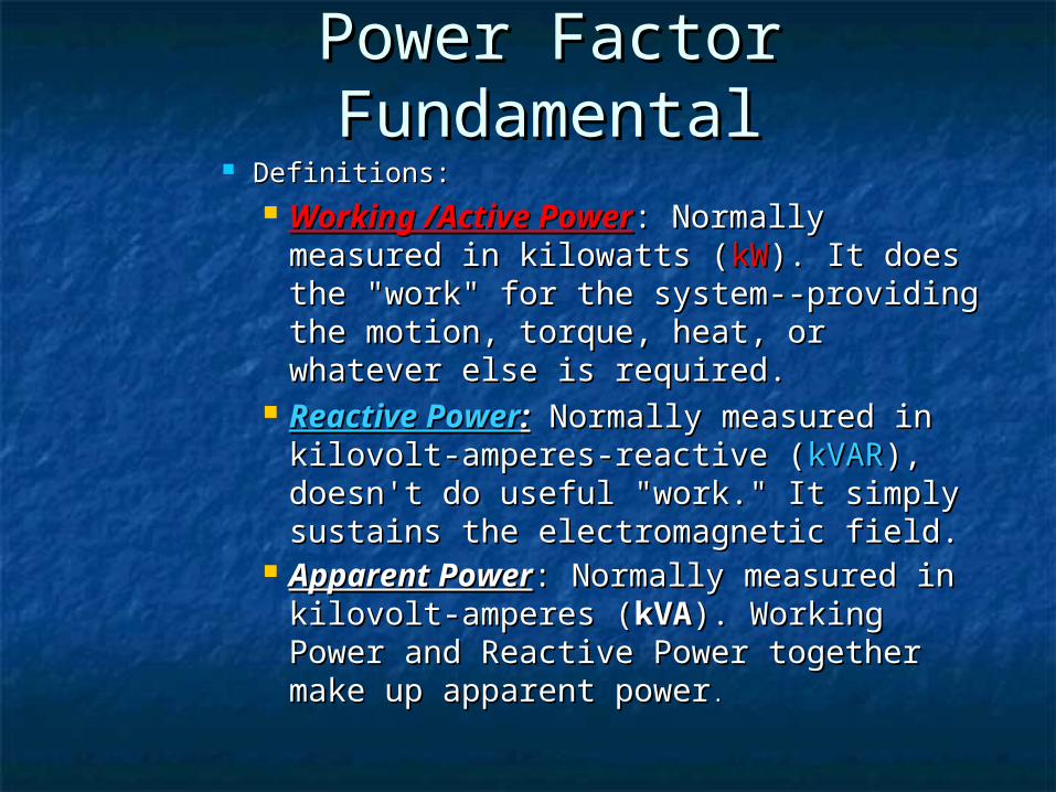
Power Factor Power Factor FundamentalFundamental
Definitions:Definitions: Working /Active PowerWorking /Active Power: Normally : Normally
measured in kilowatts (measured in kilowatts (kWkW). It does the ). It does the "work" for the system--providing the "work" for the system--providing the motion, torque, heat, or whatever else is motion, torque, heat, or whatever else is required. required.
Reactive PowerReactive Power:: Normally measured in Normally measured in kilovolt-amperes-reactive (kilovolt-amperes-reactive (kVARkVAR), doesn't ), doesn't do useful "work." It simply sustains the do useful "work." It simply sustains the electromagnetic field. electromagnetic field.
Apparent PowerApparent Power: Normally measured in : Normally measured in kilovolt-amperes (kilovolt-amperes (kVAkVA).). Working Power Working Power and Reactive Power together make up and Reactive Power together make up apparent powerapparent power. .
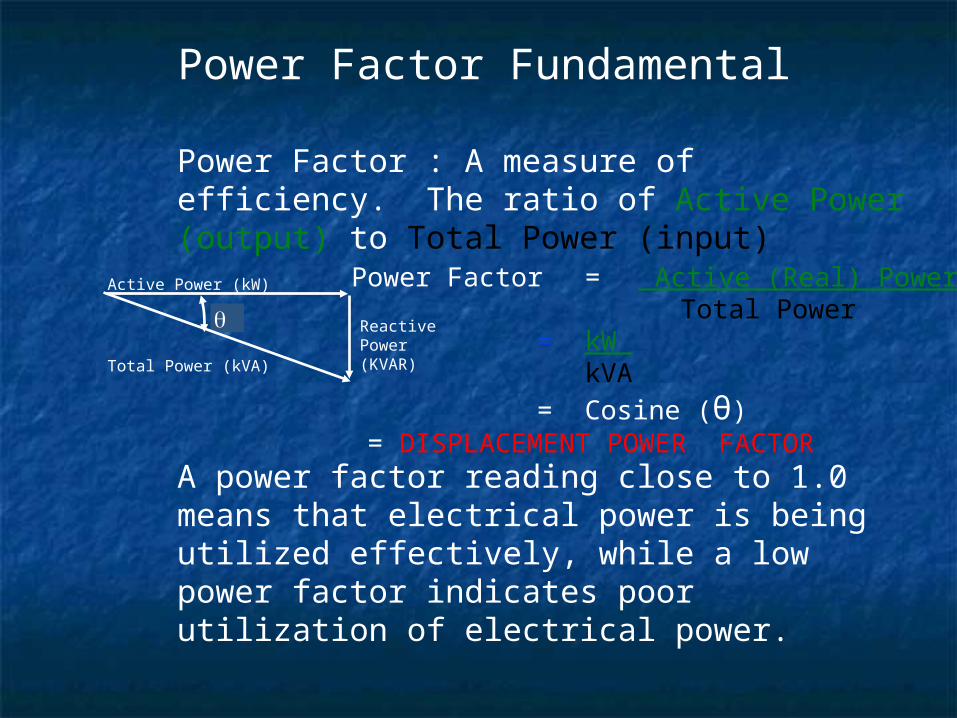
Power Factor : A measure of efficiency. The ratio of Active Power (output) to Total Power (input)
A power factor reading close to 1.0 means that electrical power is being utilized effectively, while a low power factor indicates poor utilization of electrical power.
Total Power (kVA)
Active Power (kW) Power Factor = Active (Real) Power Total Power
= kW kVA
= Cosine (θ) = DISPLACEMENT POWER FACTOR
ReactivePower(KVAR)
Power Factor Fundamental
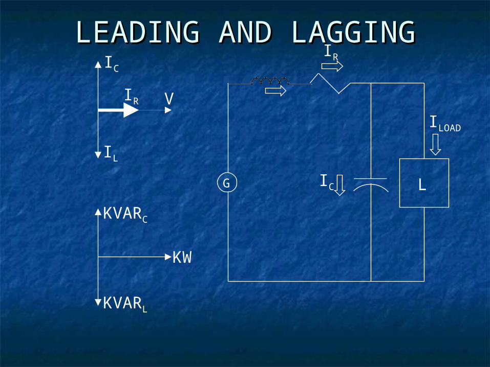
LEADING AND LAGGINGLEADING AND LAGGING
G LIC
IL
ILOAD
IR
IR V
IC
KW
KVARL
KVARC
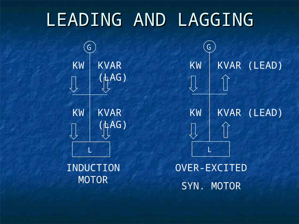
LEADING AND LAGGINGLEADING AND LAGGING
KVAR (LAG)
KVAR (LAG)
KW
KW
INDUCTION MOTOR
G
L
OVER-EXCITED
SYN. MOTOR
G
L
KVAR (LEAD)KW
KVAR (LEAD)KW
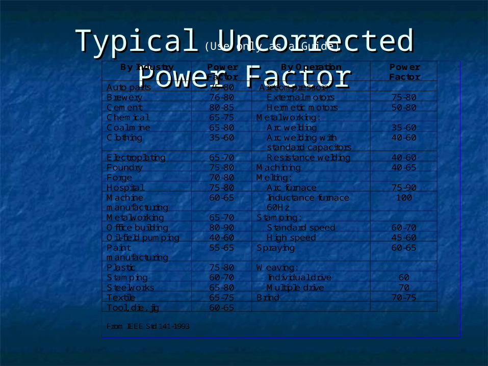
Typical Uncorrected Power Typical Uncorrected Power FactorFactor
By Industry PowerFactor
By Operation PowerFactor
Auto parts 75-80 Air compressor:Brewery 76-80 External motors 75-80Cement 80-85 Hermetic motors 50-80Chemical 65-75 Metal working:Coal mine 65-80 Arc welding 35-60Clothing 35-60 Arc welding with
standard capacitors40-60
Electroplating 65-70 Resistance welding 40-60Foundry 75-80 Machining 40-65Forge 70-80 Melting:Hospital 75-80 Arc furnace 75-90Machinemanufacturing
60-65 Inductance furnace60Hz
100
Metalworking 65-70 Stamping:Office building 80-90 Standard speed 60-70Oil-field pumping 40-60 High speed 45-60Paintmanufacturing
55-65 Spraying 60-65
Plastic 75-80 Weaving:Stamping 60-70 Individual drive 60Steelworks 65-80 Multiple drive 70Textile 65-75 Brind 70-75Tool, die, jig 60-65
From IEEE Std 141-1993
(Use only as a Guide)

WHY DO WE CARE ABOUT POWER FACTORWHY DO WE CARE ABOUT POWER FACTOR
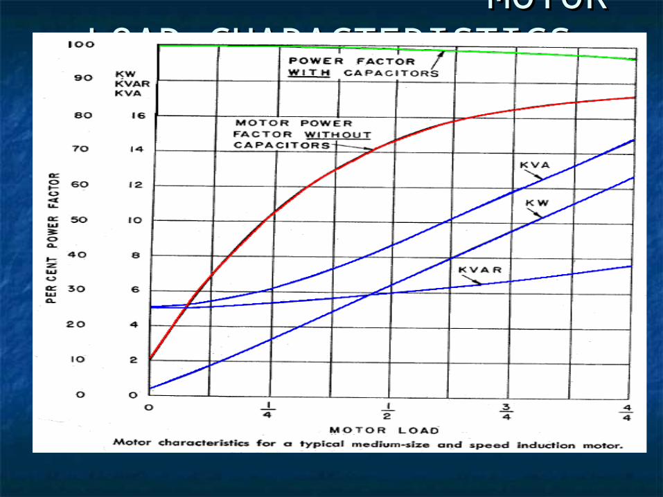
MOTOR LOAD MOTOR LOAD CHARACTERISTICSCHARACTERISTICS
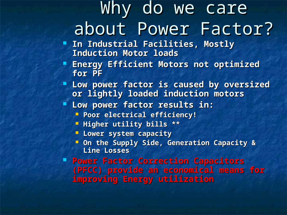
Why do we care about Why do we care about Power Factor?Power Factor?
In Industrial Facilities, Mostly Induction In Industrial Facilities, Mostly Induction Motor loadsMotor loads
Energy Efficient Motors not optimized Energy Efficient Motors not optimized for PF for PF
Low power factor is caused by oversized Low power factor is caused by oversized or lightly loaded induction motors or lightly loaded induction motors
Low power factor results in:Low power factor results in: Poor electrical efficiency!Poor electrical efficiency! Higher utility bills **Higher utility bills ** Lower system capacityLower system capacity On the Supply Side, Generation Capacity & On the Supply Side, Generation Capacity &
Line LossesLine Losses Power Factor Correction Capacitors Power Factor Correction Capacitors
(PFCC) provide an economical means for (PFCC) provide an economical means for improving Energy utilizationimproving Energy utilization
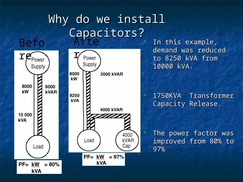
In this example, demand In this example, demand was reduced to 8250 kVA was reduced to 8250 kVA from 10000 kVA.from 10000 kVA.
1750KVA Transformer 1750KVA Transformer Capacity Release.Capacity Release.
The power factor was The power factor was improved from 80% to 97%improved from 80% to 97%
Before AfterWhy do we install Capacitors?Why do we install Capacitors?
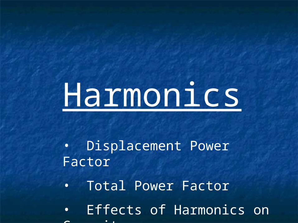
Harmonics
• Displacement Power Factor
• Total Power Factor
• Effects of Harmonics on Capacitors
v i
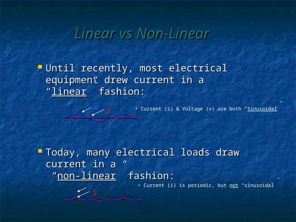
Until recently, most electrical Until recently, most electrical equipment drew current in a “equipment drew current in a “linearlinear” ” fashion:fashion:
Today, many electrical loads draw Today, many electrical loads draw current in acurrent in a “ “non-linearnon-linear” fashion:” fashion: • Current (i) is periodic, but not “sinusoidal”v
i
• Current (i) & Voltage (v) are both “Sinusoidal”
Linear vs Non-LinearLinear vs Non-Linear
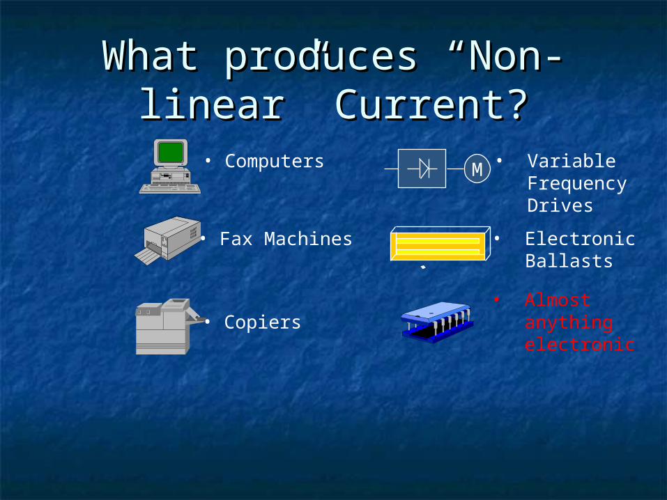
• Computers
• Fax Machines
• Copiers
M • Variable Frequency Drives
• Electronic Ballasts
• Almost anything electronic
What produces “Non-linear” What produces “Non-linear” Current?Current?
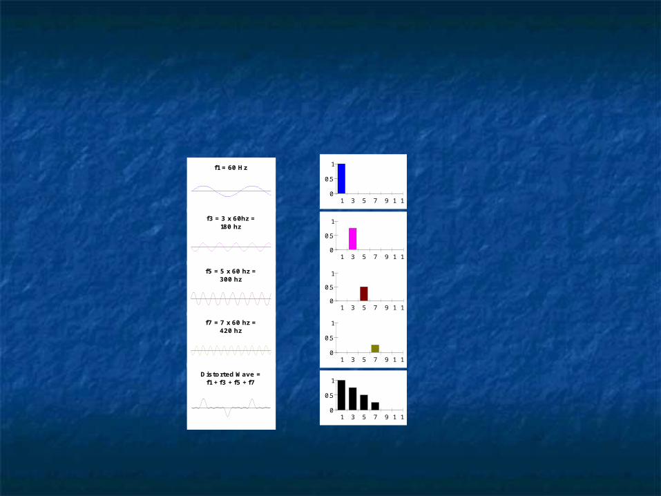
Distorted Wave =f1 + f3 + f5 + f7
0
0.5
1
1 3 5 7 9 1 1
0
0.5
1
1 3 5 7 9 1 1
0
0.5
1
1 3 5 7 9 1 1
0
0.5
1
1 3 5 7 9 1 1
0
0.5
1
1 3 5 7 9 1 1
f1 = 60 Hz
f3 = 3 x 60hz =180 hz
f5 = 5 x 60 hz =300 hz
f7 = 7 x 60 hz =420 hz
f1
f3
+
f5
+
f7
+
=
60 Hz
180 Hz
300 Hz
420 Hz
Time Domain Frequency Domain
Time vs FrequencyTime vs Frequency
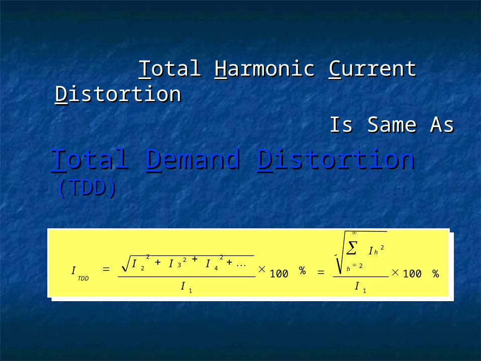
TTotal otal HHarmonic armonic CCurrent urrent DDistortionistortion
Is Same AsIs Same As
TTotal otal DDemand emand DDistortionistortion (TDD) (TDD)
I I I
I
I
ITDD
h22
4
1 1
100 100
%
h2
2 I
32
%
2
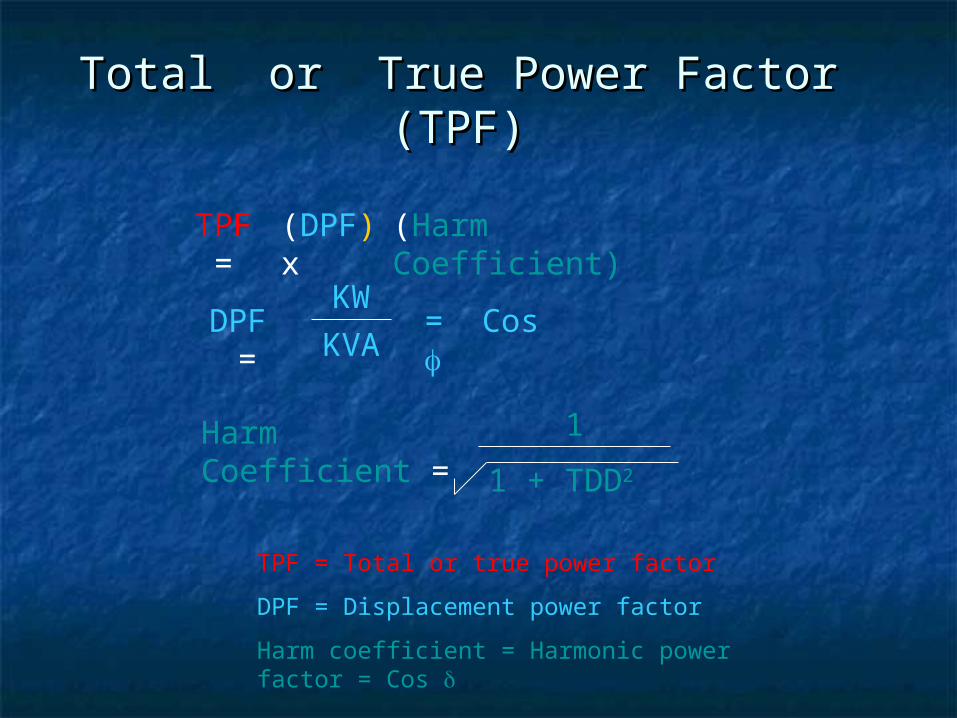
Total or True Power Factor (TPF)Total or True Power Factor (TPF)
TPF =
(DPF) x
(Harm Coefficient)
DPF =
KW
KVA= Cos
Harm Coefficient =
1
1 + TDD2
TPF = Total or true power factor
DPF = Displacement power factor
Harm coefficient = Harmonic power factor = Cos
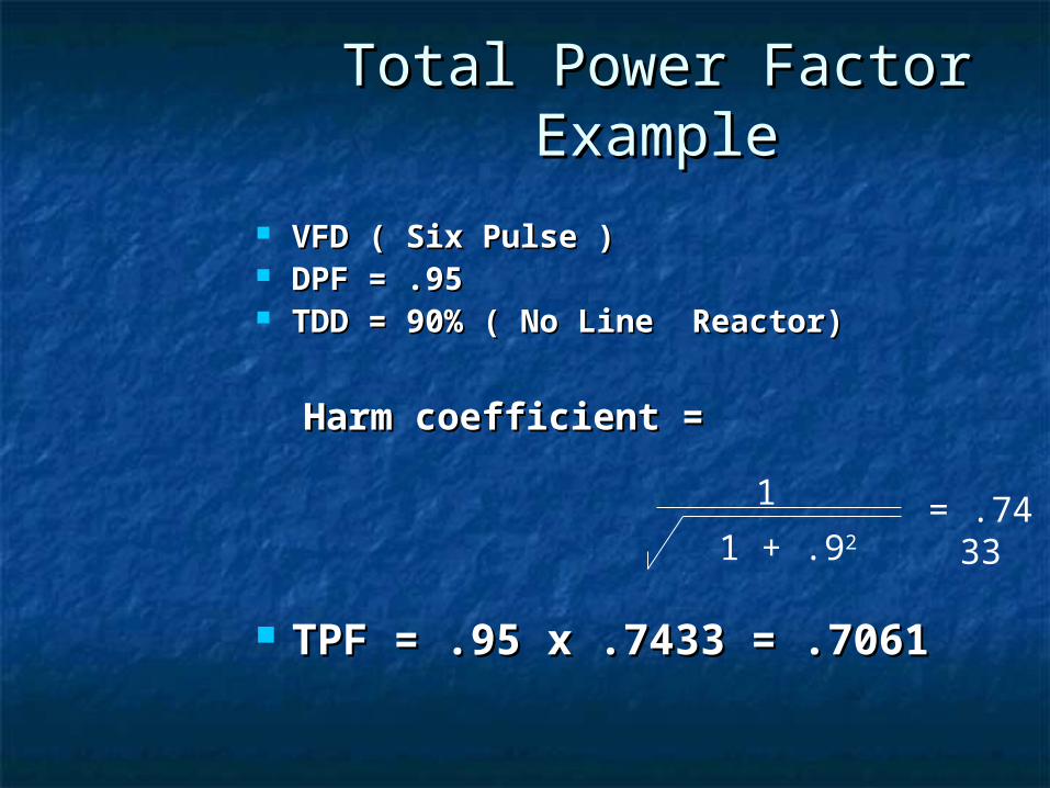
Total Power Factor Total Power Factor ExampleExample
VFD ( Six Pulse )VFD ( Six Pulse ) DPF = .95DPF = .95 TDD = 90% ( No Line Reactor)TDD = 90% ( No Line Reactor)
Harm coefficient = Harm coefficient =
TPF = .95 x .7433 = .7061TPF = .95 x .7433 = .7061
1
1 + .92= .743
3
VFD
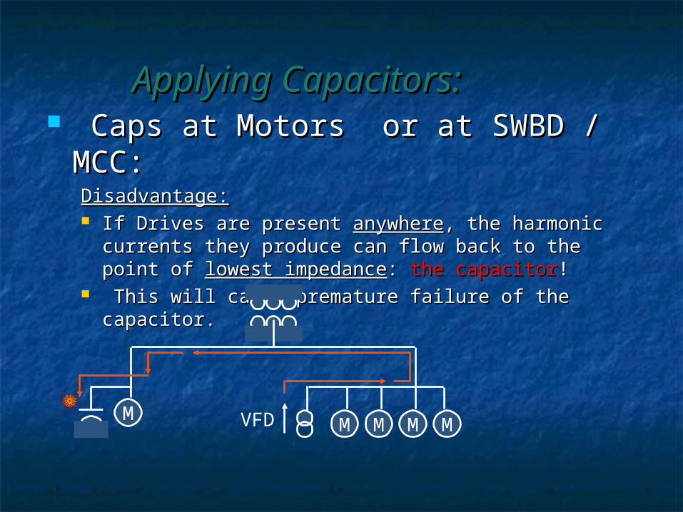
Caps at Motors or at SWBD / MCC:Caps at Motors or at SWBD / MCC:Disadvantage:Disadvantage: If Drives are present If Drives are present anywhereanywhere, the harmonic , the harmonic
currents they produce can flow back to the point of currents they produce can flow back to the point of lowest impedancelowest impedance: : the capacitorthe capacitor!!
This will cause premature failure of the capacitor.This will cause premature failure of the capacitor.
MM M M M
Applying Capacitors:Applying Capacitors:
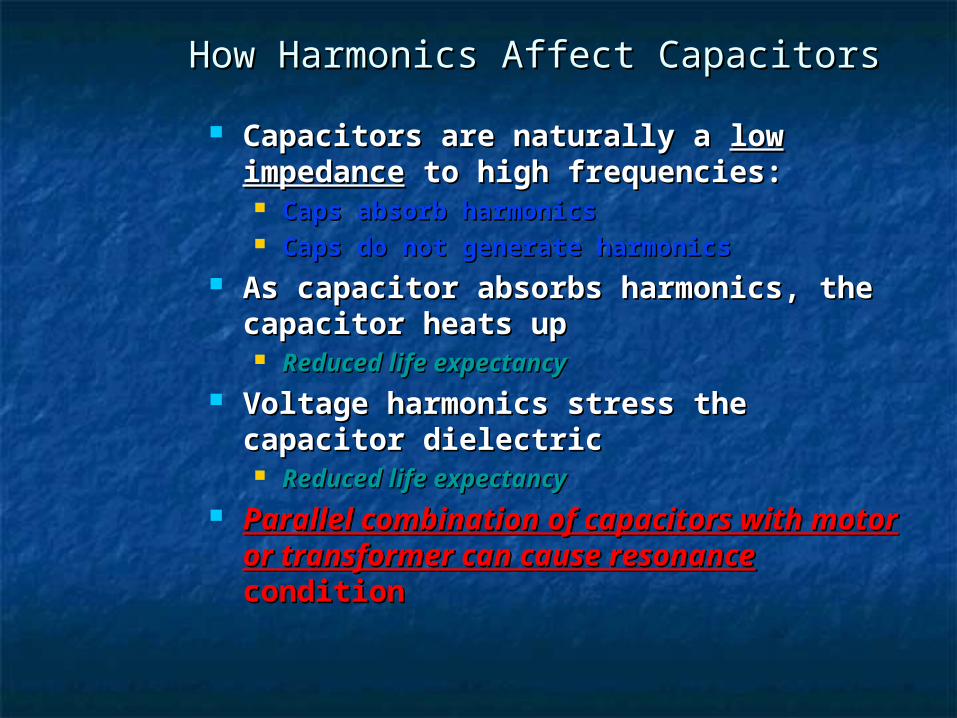
How Harmonics Affect CapacitorsHow Harmonics Affect Capacitors
Capacitors are naturally a Capacitors are naturally a low low impedanceimpedance to high frequencies: to high frequencies: Caps absorb harmonicsCaps absorb harmonics Caps do not generate harmonicsCaps do not generate harmonics
As capacitor absorbs harmonics, the As capacitor absorbs harmonics, the capacitor heats upcapacitor heats up Reduced life expectancyReduced life expectancy
Voltage harmonics stress the Voltage harmonics stress the capacitor dielectriccapacitor dielectric Reduced life expectancyReduced life expectancy
Parallel combination of capacitors Parallel combination of capacitors with motor or transformer can cause with motor or transformer can cause resonanceresonance condition condition
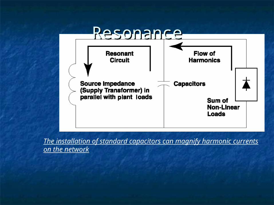
The installation of standard capacitors can magnify harmonic currents on the network
ResonanceResonance
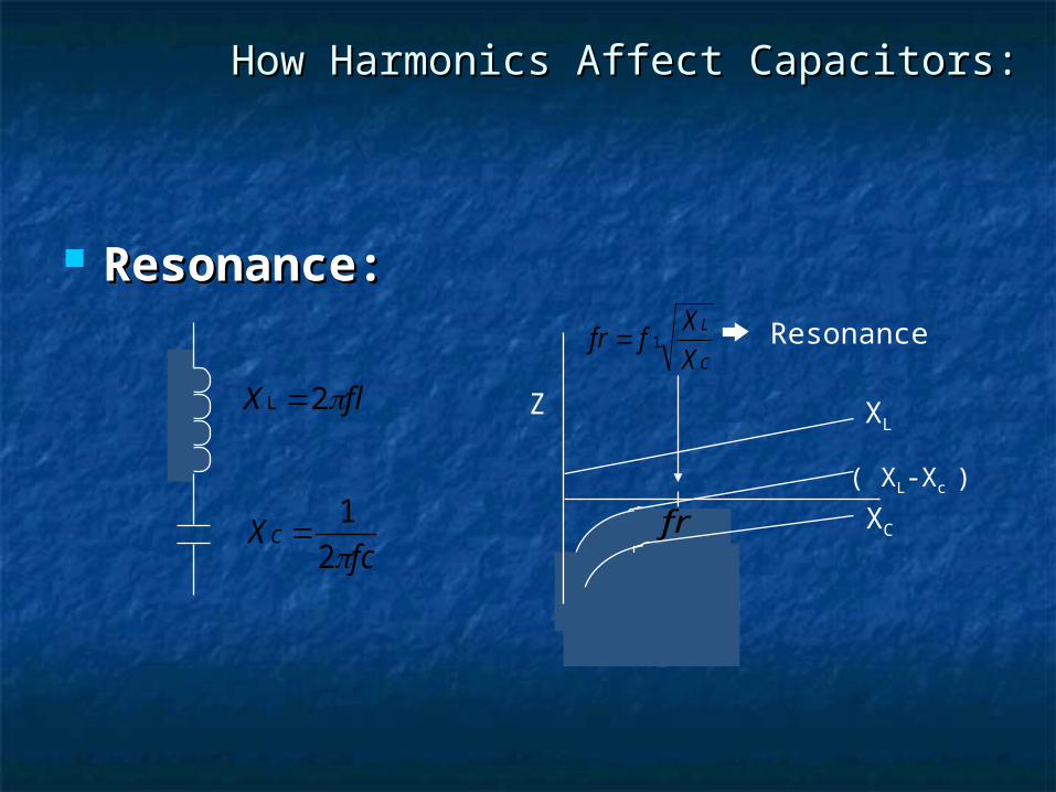
Resonance:Resonance:
X flL 2
Xfc
C 1
2
XL
XC
Z
Resonancefr fX
X
L
C 1
fr
( XL-Xc )
How Harmonics Affect Capacitors:How Harmonics Affect Capacitors:
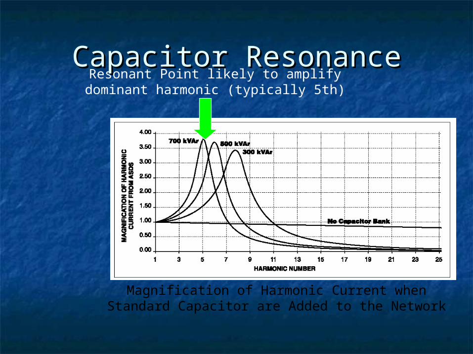
Magnification of Harmonic Current when Standard Capacitor are Added to the Network
Resonant Point likely to amplify dominant harmonic (typically 5th)
Capacitor ResonanceCapacitor Resonance
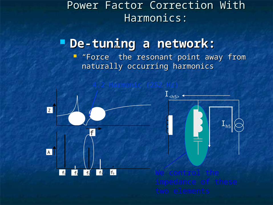
De-tuning a network:De-tuning a network: ““Force” the resonant point away from Force” the resonant point away from
naturally occurring harmonicsnaturally occurring harmonics
Ih5
I<h5>
Z
f
A
f5f3 f7 f9f1
4.2 Harmonic (252 Hz)
We control the impedance of these two elements
Power Factor Correction With Harmonics:Power Factor Correction With Harmonics:

UTILITY RATE & PFCCUTILITY RATE & PFCC
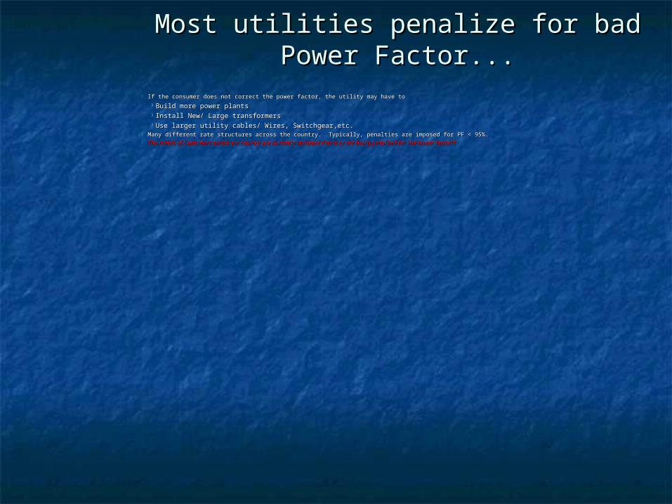
If the consumer does not correct the power factor, the utility may have to If the consumer does not correct the power factor, the utility may have to Build more power plantsBuild more power plants Install New/ Large transformers Install New/ Large transformers Use larger utility cables/ Wires, Switchgear,etc.Use larger utility cables/ Wires, Switchgear,etc.
Many different rate structures across the country. Typically, penalties are imposed for PF < 95%.Many different rate structures across the country. Typically, penalties are imposed for PF < 95%. Thousands of Customers across the country are currently unaware that they are being penalized for low power factor!!!Thousands of Customers across the country are currently unaware that they are being penalized for low power factor!!!
Most utilities penalize for bad Power Most utilities penalize for bad Power Factor...Factor...
How do utilities charge How do utilities charge for Power Factor?for Power Factor?
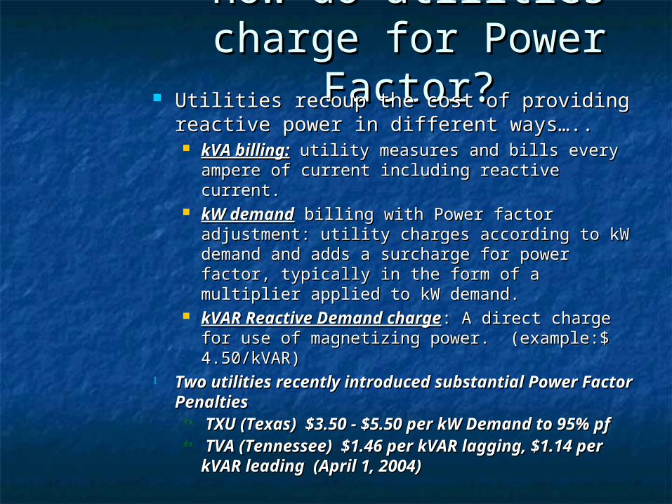
Utilities recoup the cost of providing Utilities recoup the cost of providing reactive power in different ways….. reactive power in different ways….. kVA billing:kVA billing: utility measures and bills every utility measures and bills every
ampere of current including reactive current.ampere of current including reactive current. kW demandkW demand billing with Power factor billing with Power factor
adjustment: utility charges according to kW adjustment: utility charges according to kW demand and adds a surcharge for power factor, demand and adds a surcharge for power factor, typically in the form of a multiplier applied to kW typically in the form of a multiplier applied to kW demand. demand.
kVAR Reactive Demand chargekVAR Reactive Demand charge: A direct : A direct charge for use of magnetizing power. (example:charge for use of magnetizing power. (example:$ 4.50/kVAR)$ 4.50/kVAR)
Two utilities recently introduced substantial Two utilities recently introduced substantial Power Factor PenaltiesPower Factor Penalties TXU (Texas) $3.50 - $5.50 per kW Demand TXU (Texas) $3.50 - $5.50 per kW Demand
to 95% pfto 95% pf TVA (Tennessee) $1.46 per kVAR lagging, TVA (Tennessee) $1.46 per kVAR lagging,
$1.14 per kVAR leading (April 1, 2004)$1.14 per kVAR leading (April 1, 2004)
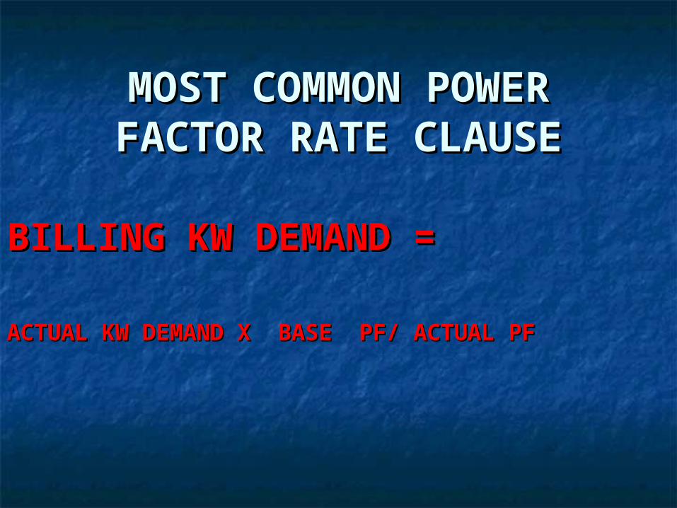
MOST COMMON POWER MOST COMMON POWER FACTOR RATE CLAUSEFACTOR RATE CLAUSE
BILLING KW DEMAND =BILLING KW DEMAND =
ACTUAL KW DEMAND X BASE PF/ ACTUAL PFACTUAL KW DEMAND X BASE PF/ ACTUAL PF
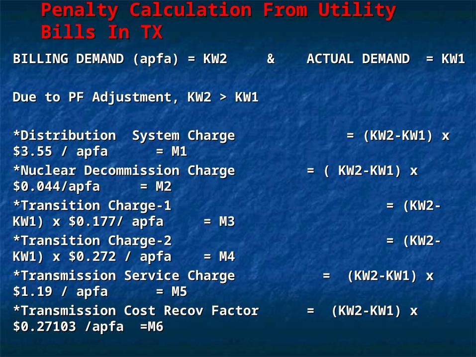
Penalty Calculation From Utility Bills Penalty Calculation From Utility Bills In TXIn TX
BILLING DEMAND (apfa) = KW2 & ACTUAL DEMAND = BILLING DEMAND (apfa) = KW2 & ACTUAL DEMAND = KW1KW1
Due to PF Adjustment, KW2 > KW1Due to PF Adjustment, KW2 > KW1
*Distribution System Charge = (KW2-KW1) x $3.55 / *Distribution System Charge = (KW2-KW1) x $3.55 / apfa = M1apfa = M1
*Nuclear Decommission Charge = ( KW2-KW1) x *Nuclear Decommission Charge = ( KW2-KW1) x $0.044/apfa = M2$0.044/apfa = M2
*Transition Charge-1 = (KW2-KW1) x $0.177/ *Transition Charge-1 = (KW2-KW1) x $0.177/ apfa = M3apfa = M3
*Transition Charge-2 = (KW2-KW1) x *Transition Charge-2 = (KW2-KW1) x $0.272 / apfa = M4$0.272 / apfa = M4
*Transmission Service Charge = (KW2-KW1) x $1.19 / *Transmission Service Charge = (KW2-KW1) x $1.19 / apfa = M5apfa = M5
*Transmission Cost Recov Factor = (KW2-KW1) x *Transmission Cost Recov Factor = (KW2-KW1) x $0.27103 /apfa =M6$0.27103 /apfa =M6
Total / Month = M1+M2+M3+M4+M5+M6 = $ / MonthTotal / Month = M1+M2+M3+M4+M5+M6 = $ / Month
CAPACITOR LOCATION & TYPECAPACITOR LOCATION & TYPE
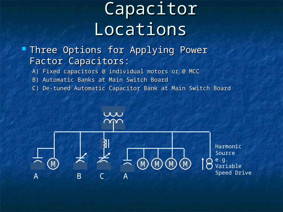
Three Options for Applying Power Factor Three Options for Applying Power Factor Capacitors:Capacitors:A) Fixed capacitors @ individual motors or @ MCCA) Fixed capacitors @ individual motors or @ MCC
B) Automatic Banks at Main Switch BoardB) Automatic Banks at Main Switch Board
C) De-tuned Automatic Capacitor Bank at Main Switch BoardC) De-tuned Automatic Capacitor Bank at Main Switch Board
M M M M M
A B C A
Harmonic Source e.g. Variable Speed Drive
Capacitor Capacitor LocationsLocations
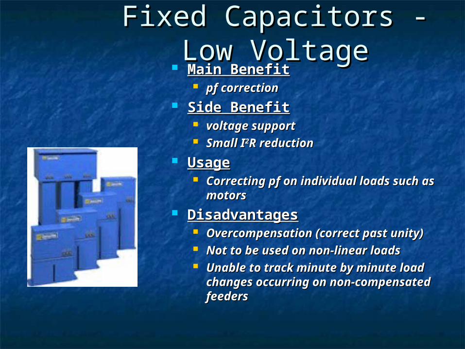
Fixed Capacitors - Low Fixed Capacitors - Low VoltageVoltage
Main BenefitMain Benefit pf correctionpf correction
Side BenefitSide Benefit voltage supportvoltage support Small ISmall I22R reductionR reduction
UsageUsage Correcting pf on individual loads such Correcting pf on individual loads such
as motorsas motors DisadvantagesDisadvantages
Overcompensation (correct past Overcompensation (correct past unity)unity)
Not to be used on non-linear loadsNot to be used on non-linear loads Unable to track minute by minute Unable to track minute by minute
load changes occurring on non-load changes occurring on non-compensated feederscompensated feeders
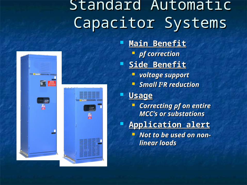
Standard Automatic Standard Automatic Capacitor SystemsCapacitor Systems
Main BenefitMain Benefit pf correctionpf correction
Side BenefitSide Benefit voltage supportvoltage support Small ISmall I22R reductionR reduction
UsageUsage Correcting pf on Correcting pf on
entire MCC’s or entire MCC’s or substationssubstations
Application alertApplication alert Not to be used on Not to be used on
non-linear loadsnon-linear loads
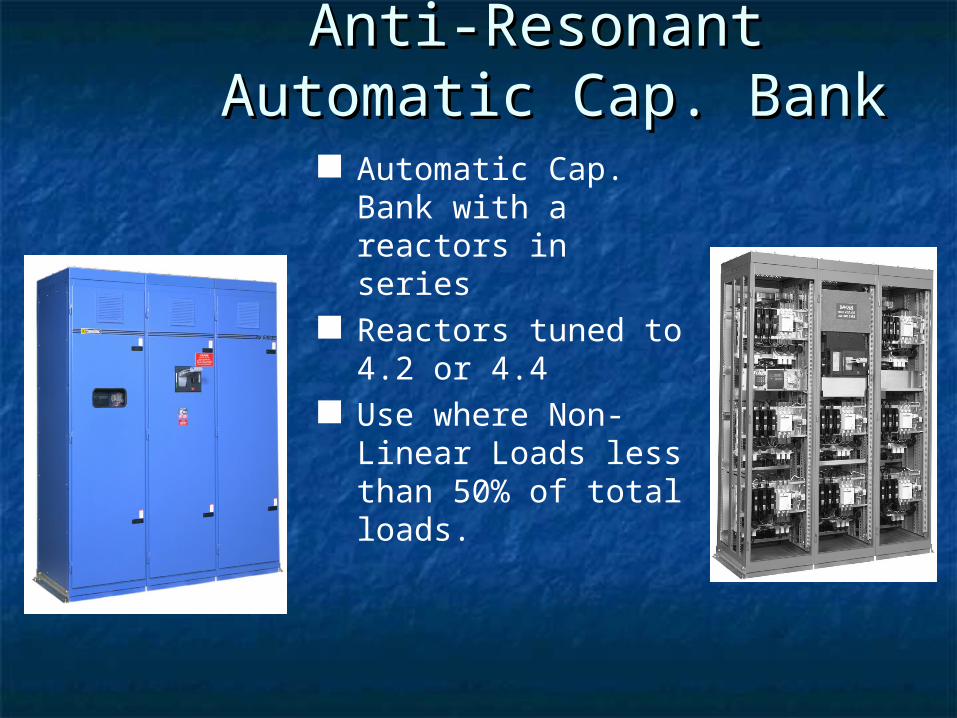
Automatic Cap. Bank with a reactors in series
Reactors tuned to 4.2 or 4.4
Use where Non-Linear Loads less than 50% of total loads.
Anti-Resonant Anti-Resonant Automatic Cap. BankAutomatic Cap. Bank
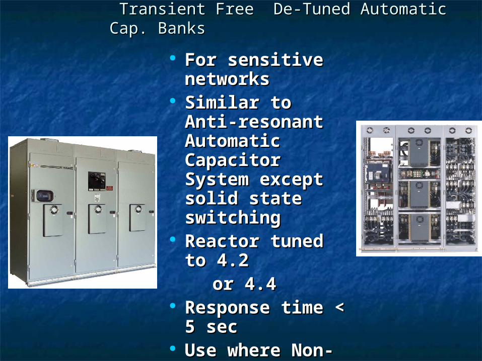
For sensitive For sensitive networksnetworks
Similar to Anti-Similar to Anti-resonant resonant Automatic Automatic Capacitor Capacitor System except System except solid state solid state switchingswitching
Reactor tuned Reactor tuned to 4.2to 4.2
or 4.4or 4.4 Response time Response time
< 5 sec< 5 sec Use where Non-Use where Non-
Linear Loads < Linear Loads < 50% of Total 50% of Total Loads.Loads.
Transient Free De-Tuned Automatic Transient Free De-Tuned Automatic Cap. BanksCap. Banks
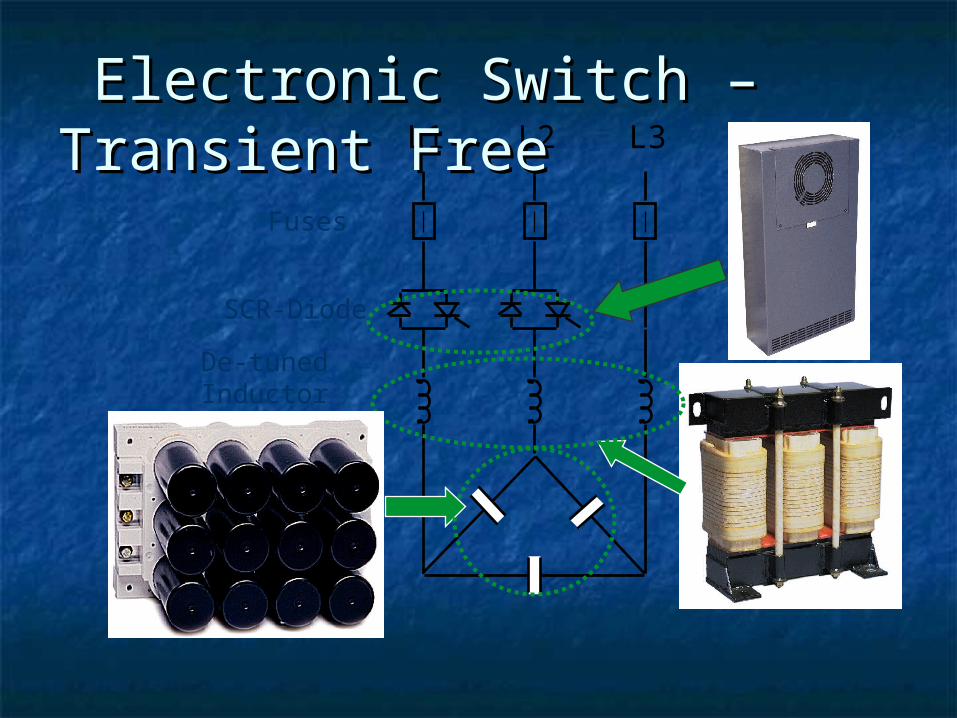
Fuses
SCR-Diode
De-tunedInductor
L1 L2 L3 Electronic Switch –Electronic Switch –Transient FreeTransient Free
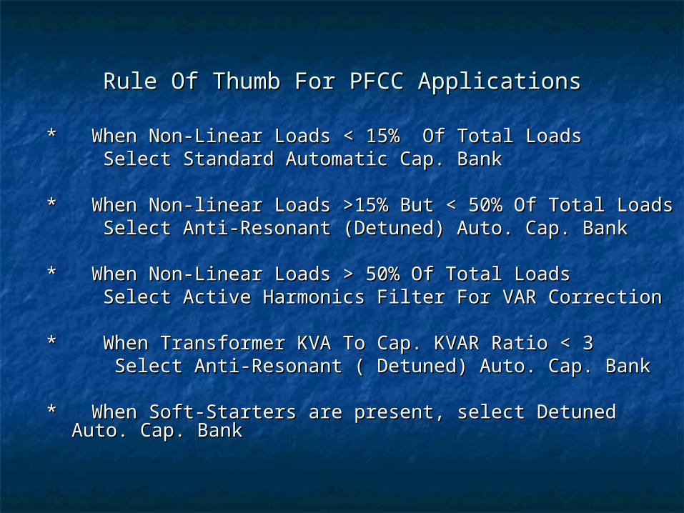
Rule Of Thumb For PFCC ApplicationsRule Of Thumb For PFCC Applications
* When Non-Linear Loads < 15% Of Total Loads * When Non-Linear Loads < 15% Of Total Loads Select Standard Automatic Cap. BankSelect Standard Automatic Cap. Bank
* When Non-linear Loads >15% But < 50% Of Total Loads* When Non-linear Loads >15% But < 50% Of Total Loads Select Anti-Resonant (Detuned) Auto. Cap. BankSelect Anti-Resonant (Detuned) Auto. Cap. Bank
* When Non-Linear Loads > 50% Of Total Loads* When Non-Linear Loads > 50% Of Total Loads Select Active Harmonics Filter For VAR CorrectionSelect Active Harmonics Filter For VAR Correction
* When Transformer KVA To Cap. KVAR Ratio < 3 * When Transformer KVA To Cap. KVAR Ratio < 3 Select Anti-Resonant ( Detuned) Auto. Cap. BankSelect Anti-Resonant ( Detuned) Auto. Cap. Bank
* When Soft-Starters are present, select Detuned Auto. Cap. * When Soft-Starters are present, select Detuned Auto. Cap. BankBank
ACTIVE FILTER in VAR Correction ACTIVE FILTER in VAR Correction ModeMode
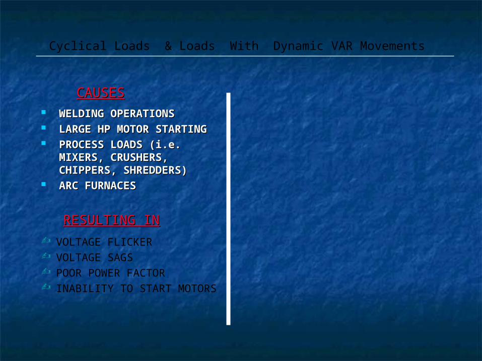
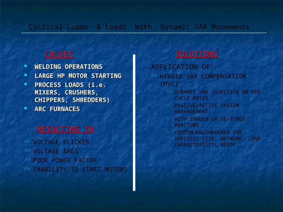
WELDING OPERATIONSWELDING OPERATIONS LARGE HP MOTOR LARGE HP MOTOR
STARTINGSTARTING PROCESS LOADS (i.e. PROCESS LOADS (i.e.
MIXERS, CRUSHERS, MIXERS, CRUSHERS, CHIPPERS, SHREDDERS)CHIPPERS, SHREDDERS)
ARC FURNACESARC FURNACES
CAUSESCAUSES
Cyclical Loads & Loads With Dynamic VAR Movements
RESULTING INRESULTING IN
VOLTAGE FLICKER VOLTAGE SAGS POOR POWER FACTOR INABILITY TO START MOTORS
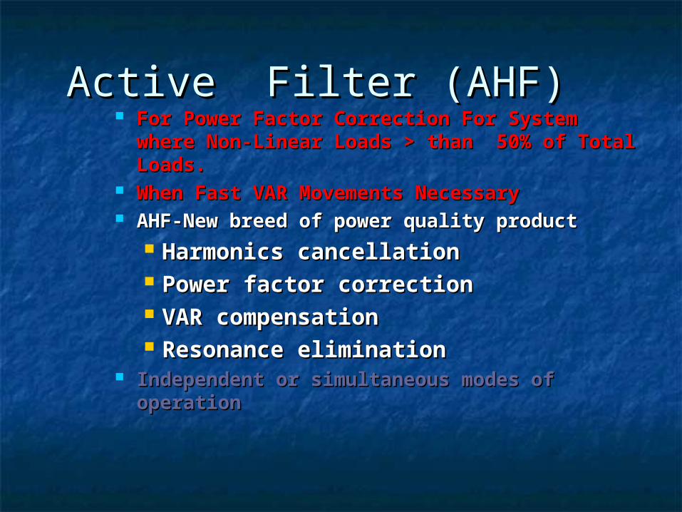
Active Filter (AHF)Active Filter (AHF) For Power Factor Correction For System For Power Factor Correction For System
where Non-Linear Loads > than 50% of where Non-Linear Loads > than 50% of Total Loads.Total Loads.
When Fast VAR Movements NecessaryWhen Fast VAR Movements Necessary AHF-New breed of power quality productAHF-New breed of power quality product
Harmonics cancellationHarmonics cancellation Power factor correctionPower factor correction VAR compensationVAR compensation Resonance eliminationResonance elimination
Independent or simultaneous modes of Independent or simultaneous modes of operationoperation
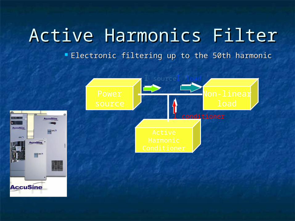
Active Harmonics FilterActive Harmonics Filter Electronic filtering up to the 50th harmonicElectronic filtering up to the 50th harmonic
I source I load
Powersource
Non-linearload
ActiveHarmonic
Conditioner
I conditioner
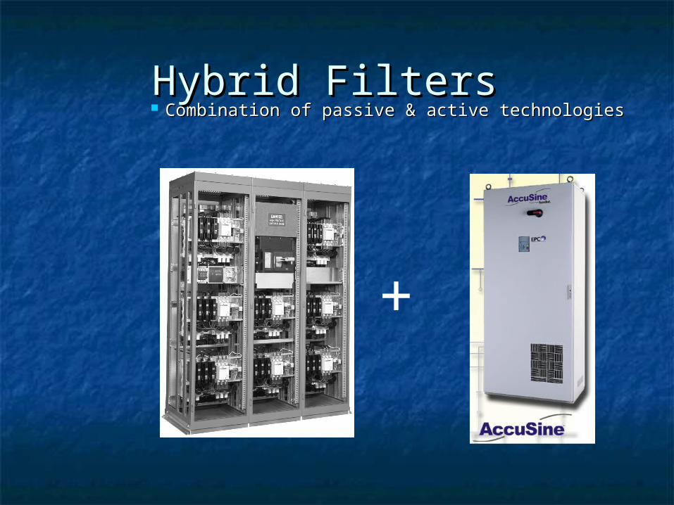
Hybrid Filters Hybrid Filters Combination of passive & active technologiesCombination of passive & active technologies
+
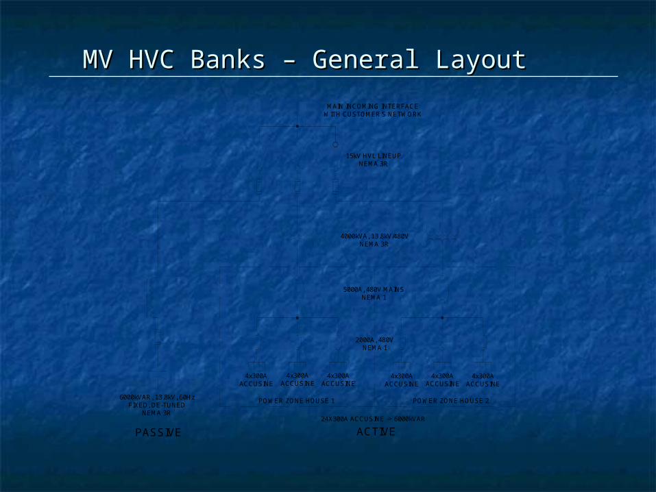
6000kVAR, 13.8kV, 60HzFIXED, DE-TUNED
NEMA 3R
MAIN INCOMING INTERFACEWITH CUSTOMER'S NETWORK
15kV HVL LINEUPNEMA 3R
4000kVA, 13.8kV/480VNEMA 3R
5000A, 480V MAINSNEMA 1
2000A, 480VNEMA 1
4x300AACCUSINE
4x300AACCUSINE
4x300AACCUSINE
4x300AACCUSINE
4x300AACCUSINE
4x300AACCUSINE
POWER ZONE HOUSE 1 POWER ZONE HOUSE 2
24X300A ACCUSINE -> 6000kVAR
PASSIVE ACTIVE
MV HVC Banks – General LayoutMV HVC Banks – General Layout
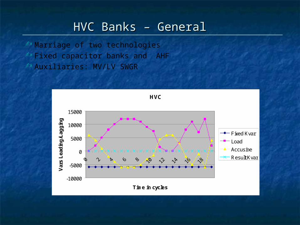
HVCHVC Banks – General Banks – General
HVC
-10000
-5000
0
5000
10000
15000
0 2 4 6 8 10 12 14 16 18
Time in cycles
Var
s L
ead
ing
/Lag
gin
g
Fixed Kvar
Load
Accusine
Result Kvar
Marriage of two technologies Fixed capacitor banks and AHF Auxiliaries: MV/LV SWGR
WELDING OPERATIONSWELDING OPERATIONS LARGE HP MOTOR LARGE HP MOTOR
STARTINGSTARTING PROCESS LOADS (i.e. PROCESS LOADS (i.e.
MIXERS, CRUSHERS, MIXERS, CRUSHERS, CHIPPERS, SHREDDERS)CHIPPERS, SHREDDERS)
ARC FURNACESARC FURNACES
APPLICATION OF: HYBRID VAR COMPENSATION
(HVC) DYNAMIC VAR INJECTION ON PER
CYCLE BASIS PASSIVE/ACTIVE SYSTEM
ARRANGEMENT WITH INRUSH OR DE-TUNED
REACTORS CUSTOM-ENGINREERED FOR
SPECIFIC SITE, NETWORK, LOAD CHARACTERISTIC NEEDS
CAUSESCAUSES SOLUTIONSSOLUTIONS
Cyclical Loads & Loads With Dynamic VAR Movements
RESULTING INRESULTING IN
VOLTAGE FLICKER VOLTAGE SAGS POOR POWER FACTOR INABILITY TO START MOTORS
CAPACITOR APPLICATIONS CAPACITOR APPLICATIONS AT AT MOTOR TERMINAL MOTOR TERMINAL
> Motor Overload Protection > Motor Overload Protection
> Re-closure Issue – Jogging , Reversing, Inching , Plugging > Re-closure Issue – Jogging , Reversing, Inching , Plugging ApplicationsApplications
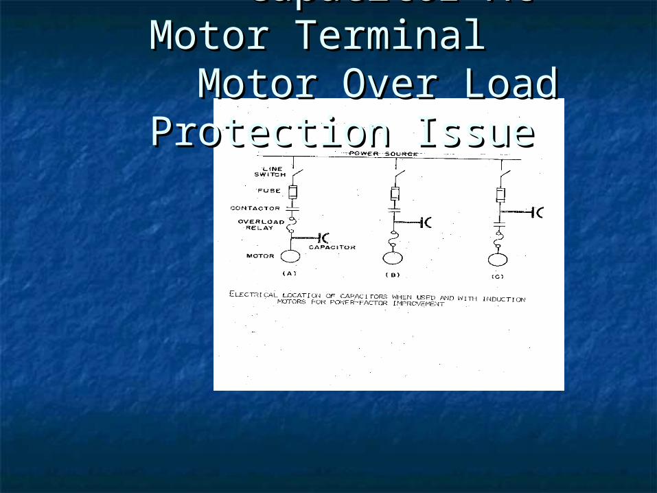
Capacitor At Motor Capacitor At Motor TerminalTerminal Motor Over Load Motor Over Load Protection IssueProtection Issue
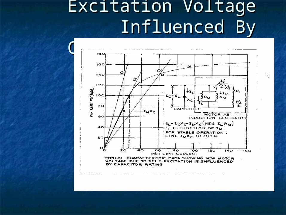
Motor Self-Motor Self-Excitation Voltage Excitation Voltage Influenced By Influenced By Capacitor RatingsCapacitor Ratings
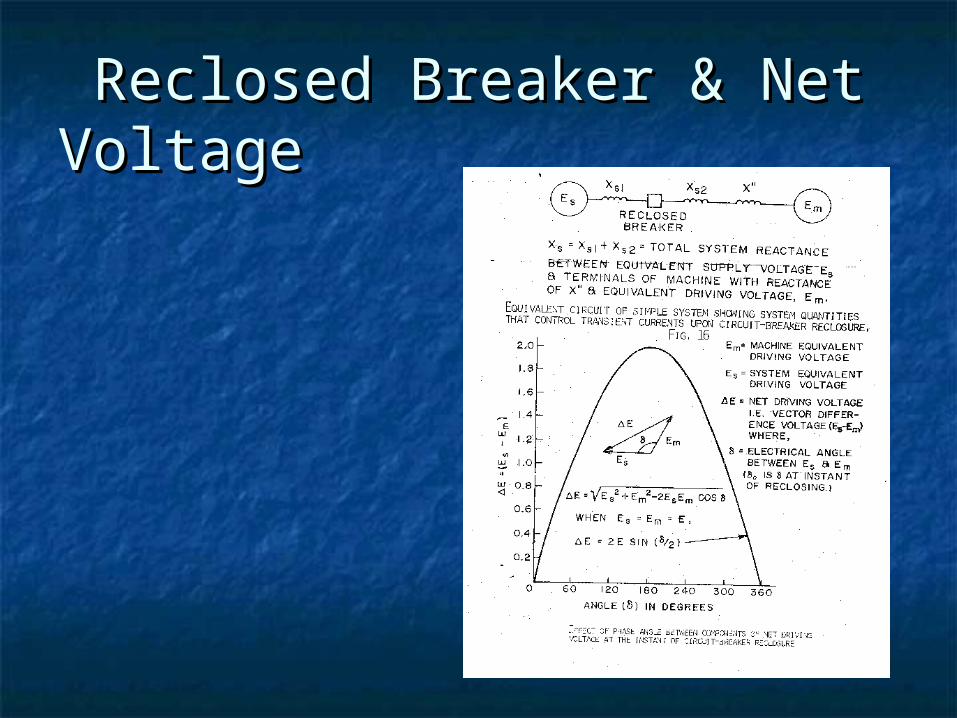
Reclosed Breaker & Net Reclosed Breaker & Net VoltageVoltage
CAPACITOR APPLICATION ISSUESCAPACITOR APPLICATION ISSUES
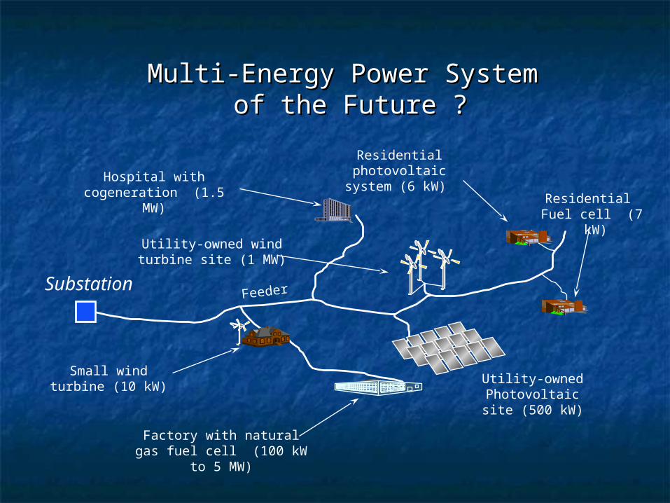
Multi-Energy Power System Multi-Energy Power System of the Future ?of the Future ?
Hospital with cogeneration (1.5 MW)
SubstationFeeder
Residential photovoltaic system (6 kW)
Utility-owned Photovoltaic site (500
kW)
Small wind turbine (10 kW)
Factory with natural gas fuel cell (100 kW to 5 MW)
Residential Fuel cell (7 kW)
Utility-owned wind turbine site (1 MW)
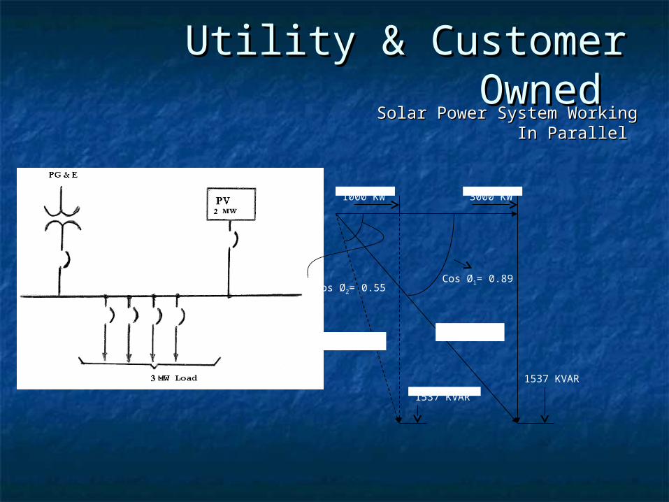
Cos Ø2= 0.55Cos Ø1= 0.89
1000 KW 3000 KW
1537 KVAR
1537 KVAR
1818 KVA1537 KVA
Utility & Customer Owned Utility & Customer Owned Solar Power System WorkingSolar Power System Working
In Parallel In Parallel
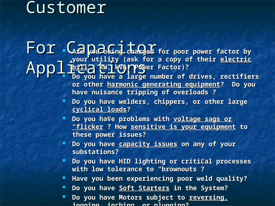
Key Questions Key Questions to ask Customerto ask Customer For Capacitor For Capacitor ApplicationsApplications Are you being charged for poor power factor by Are you being charged for poor power factor by
your utility (ask for a copy of their your utility (ask for a copy of their electric billelectric bill - - kW, kVA, Power Factor)?kW, kVA, Power Factor)?
Do you have a large number of drives, rectifiers Do you have a large number of drives, rectifiers or other or other harmonic generating equipmentharmonic generating equipment? Do ? Do you have nuisance tripping of overloads ?you have nuisance tripping of overloads ?
Do you have welders, chippers, or other large Do you have welders, chippers, or other large cyclical loadscyclical loads??
Do you have problems with Do you have problems with voltage sags or voltage sags or “flicker“flicker”? How ”? How sensitive is your equipmentsensitive is your equipment to to these power issues?these power issues?
Do you have Do you have capacity issuescapacity issues on any of your on any of your substations?substations?
Do you have HID lighting or critical processes Do you have HID lighting or critical processes with low tolerance to “brownouts”?with low tolerance to “brownouts”?
Have you been experiencing poor weld quality?Have you been experiencing poor weld quality? Do you have Do you have Soft StartersSoft Starters in the System? in the System? Do you have Motors subject to Do you have Motors subject to reversing, reversing,
jogging, inching, orjogging, inching, or plugging?plugging?
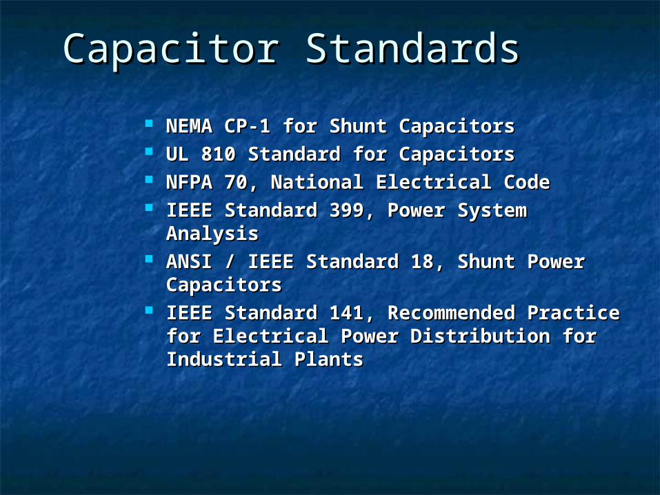
Capacitor Capacitor StandardsStandards
NEMA CP-1 for Shunt CapacitorsNEMA CP-1 for Shunt Capacitors UL 810 Standard for CapacitorsUL 810 Standard for Capacitors NFPA 70, National Electrical CodeNFPA 70, National Electrical Code IEEE Standard 399, Power System IEEE Standard 399, Power System
AnalysisAnalysis ANSI / IEEE Standard 18, Shunt Power ANSI / IEEE Standard 18, Shunt Power
CapacitorsCapacitors IEEE Standard 141, Recommended IEEE Standard 141, Recommended
Practice for Electrical Power Practice for Electrical Power Distribution for Industrial PlantsDistribution for Industrial Plants
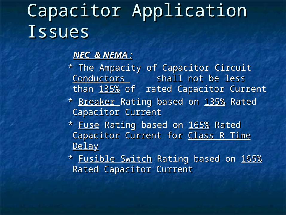
Other Capacitor Other Capacitor Application IssuesApplication Issues
NEC & NEMA :NEC & NEMA :
* The Ampacity of Capacitor Circuit * The Ampacity of Capacitor Circuit Conductors Conductors shall not be less than shall not be less than 135%135% of rated Capacitor Current of rated Capacitor Current
* * Breaker Breaker Rating based on Rating based on 135%135% Rated Rated Capacitor CurrentCapacitor Current
* * FuseFuse Rating based on Rating based on 165%165% Rated Rated Capacitor Current for Capacitor Current for Class R Time DelayClass R Time Delay
* * Fusible SwitchFusible Switch Rating based on Rating based on 165%165% Rated Capacitor CurrentRated Capacitor Current
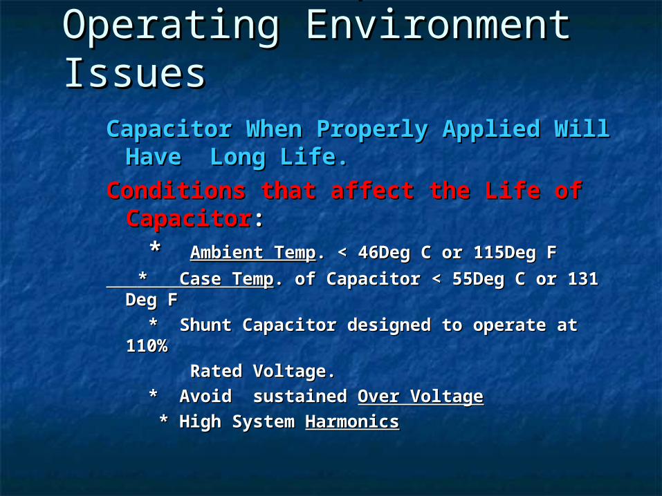
Capacitor Operating Capacitor Operating Environment IssuesEnvironment Issues
Capacitor When Properly Applied Will Capacitor When Properly Applied Will Have Long Life.Have Long Life.
Conditions that affect the Life of Conditions that affect the Life of CapacitorCapacitor::
* * Ambient TempAmbient Temp. < 46Deg C or 115Deg F. < 46Deg C or 115Deg F
* Case Temp* Case Temp. of Capacitor < 55Deg C or 131 . of Capacitor < 55Deg C or 131 Deg FDeg F
* Shunt Capacitor designed to operate at 110%* Shunt Capacitor designed to operate at 110%
Rated Voltage. Rated Voltage.
* Avoid sustained * Avoid sustained Over VoltageOver Voltage
* High System * High System HarmonicsHarmonics
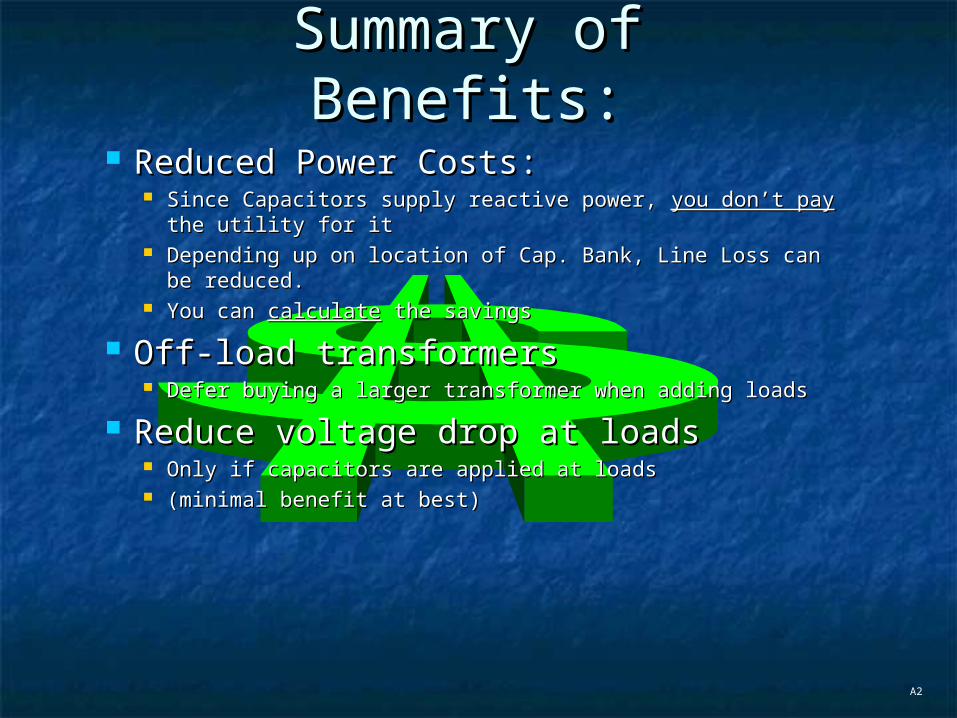
Reduced Power Costs:Reduced Power Costs: Since Capacitors supply reactive power, Since Capacitors supply reactive power, you don’t payyou don’t pay the the
utility for itutility for it Depending up on location of Cap. Bank, Line Loss can be Depending up on location of Cap. Bank, Line Loss can be
reduced.reduced. You can You can calculatecalculate the savings the savings
Off-load transformersOff-load transformers Defer buying a larger transformer when adding loadsDefer buying a larger transformer when adding loads
Reduce voltage drop at loadsReduce voltage drop at loads Only if capacitors are applied at loadsOnly if capacitors are applied at loads (minimal benefit at best)(minimal benefit at best)
A2
Summary of Summary of Benefits:Benefits:

Thank You !Thank You ! Questions? Questions?


