ITER Fuelling and Glow Discharge Cleaning System Overview S. Maruyama 1 , G. Kiss 1 , R.A. Pitts 1 , S. Putvinski 1 , M. Shimada 1 , M. Sugihara 1 , Y. Yang 1 , M. O’Connor 2 , R. O’Connor 2 , B. Li 3 , W. Li 3 , Y. Pan 3 , M. Wang 3 , L.R. Baylor 4 , S.J. Meitner 4 and D. Douai 5 E-mail: [email protected]1 ITER Organization, Route de Vinon sur Verdon, 13115 St. Paul lez Durance, France 2 Babcock International, Oxfordshire, United Kingdom 3 Southwest Institute of Physics, Chengdu, China 4 Oak Ridge National Laboratory, Oak Ridge, TN, USA 5 CEA-IRFM, Cadarache, France Abstract The ITER Fuelling and Wall Conditioning (FWC) System consists of 4 major sub-systems: the Gas Injection System (GIS), Pellet Injection System (PIS), Disruption Mitigation System (DMS) and Glow Discharge Cleaning System (GDC). The conceptual design of the GIS has been completed succeeding to engineering and detailed system design phases. The Fusion Power Shutdown System operation scheme and its interface with the Central Safety and Interlock Systems are studied. The engineering R&D of key elements of PIS is ongoing at the Unites States Domestic Agency in parallel with the conceptual design. Due to design evolution of in-vessel coil feeder, the PIS has been relocated to avoid crash while maintaining 120 degree toroidal uniformity at divertor level. The preliminary physics requirements for DMS has been defined its location is finalized; 3 diagnostics upper ports and 1 equatorial diagnostics port plug. The GDC has been relocated from divertor level to upper and equatorial level and detached from the in-vessel viewing system. This allows the fixed anode design and solves vulnerability issues associated with movable anode with flexible hose. This paper summarizes the progress and perspectives of ITER FWC system development and design. 1. Introduction The ITER Fuelling and Wall Conditioning (FWC) System consists of 4 major sub-systems: the Gas Injection System (GIS), Pellet Injection System (PIS), Disruption Mitigation System (DMS) and Glow Discharge Cleaning System (GDC). Each Sub-system provides the following functions. (1) Gas Injection System - Injection of fuel gases for plasma density control and fuel replenishment for helium removal. - Injection of impurity gases for radiative cooling enhancement, divertor detachment control and controlled discharge termination. - Injection of minority species to improve coupling of radio frequency heating waves with the plasma. - Provision of an emergency fusion power shutdown as a safety function. - Supply of H 2 or D 2 gases to the heating and diagnostic Neutral Beam (NB) injectors. - Supply of fuelling gases (D 2 , H 2 & T 2 ) and impurity gases (N 2 , Ar, or Ne) to the PIS. - Supply of gases for wall conditioning. (2) Pellet Injection System - Injection of hydrogen isotope ice pellets for plasma density control. ITR/P5-24
Transcript
ITER Fuelling and Glow Discharge Cleaning System Overview
S. Maruyama1, G. Kiss
1, R.A. Pitts
1, S. Putvinski
1, M. Shimada
1, M. Sugihara
1, Y. Yang
1,
M. O’Connor2, R. O’Connor
2, B. Li
3, W. Li
3, Y. Pan
3, M. Wang
3,
L.R. Baylor4, S.J. Meitner
4 and D. Douai
5
E-mail: [email protected] 1ITER Organization, Route de Vinon sur Verdon, 13115 St. Paul lez Durance, France
2Babcock International, Oxfordshire, United Kingdom
3Southwest Institute of Physics, Chengdu, China
4Oak Ridge National Laboratory, Oak Ridge, TN, USA
5CEA-IRFM, Cadarache, France
Abstract
The ITER Fuelling and Wall Conditioning (FWC) System consists of 4 major sub-systems: the Gas Injection
System (GIS), Pellet Injection System (PIS), Disruption Mitigation System (DMS) and Glow Discharge
Cleaning System (GDC).
The conceptual design of the GIS has been completed succeeding to engineering and detailed system design
phases. The Fusion Power Shutdown System operation scheme and its interface with the Central Safety and
Interlock Systems are studied. The engineering R&D of key elements of PIS is ongoing at the Unites States
Domestic Agency in parallel with the conceptual design. Due to design evolution of in-vessel coil feeder,
the PIS has been relocated to avoid crash while maintaining 120 degree toroidal uniformity at divertor level.
The preliminary physics requirements for DMS has been defined its location is finalized; 3 diagnostics upper
ports and 1 equatorial diagnostics port plug. The GDC has been relocated from divertor level to upper and
equatorial level and detached from the in-vessel viewing system. This allows the fixed anode design and
solves vulnerability issues associated with movable anode with flexible hose.
This paper summarizes the progress and perspectives of ITER FWC system development and design.
1. Introduction
The ITER Fuelling and Wall Conditioning (FWC) System consists of 4 major sub-systems: the
Gas Injection System (GIS), Pellet Injection System (PIS), Disruption Mitigation System
(DMS) and Glow Discharge Cleaning System (GDC).
Each Sub-system provides the following functions.
(1) Gas Injection System
− Injection of fuel gases for plasma density control and fuel replenishment for helium
removal.
− Injection of impurity gases for radiative cooling enhancement, divertor detachment
control and controlled discharge termination.
− Injection of minority species to improve coupling of radio frequency heating waves with
the plasma.
− Provision of an emergency fusion power shutdown as a safety function.
− Supply of H2 or D2 gases to the heating and diagnostic Neutral Beam (NB) injectors.
− Supply of fuelling gases (D2, H2 & T2) and impurity gases (N2, Ar, or Ne) to the PIS.
− Supply of gases for wall conditioning.
(2) Pellet Injection System
− Injection of hydrogen isotope ice pellets for plasma density control.
ITR/P5-24
− Injection of impurity ice pellets into the plasma for studies of impurity transport and
possible radiative cooling enhancement at the edge.
− Provision of pellet injection into the edge plasma for control of Edge Localized Modes
(ELMs).
(3) Disruption Mitigation System
− Rapid injection of a massive number of particles into the vacuum vessel to mitigate
excessive thermal and electromagnetic loads and suppression of runaway electrons.
(4) Glow Discharge Cleaning System
− Reduction and control of impurity and hydrogenic fuel out-gassing from plasma-facing
components and possible contribution to in-vessel tritium inventory control.
2. System Requirements and Configuration
Since the previous report on the status of the ITER FWC system [1], a significant effort has
been invested in finding the best possible compromise for the distribution of the various entry
points for the various systems. For example, the GDC and DMS must compete for precious
space/volume in the various port plugs which are already highly occupied by other systems (e.g.
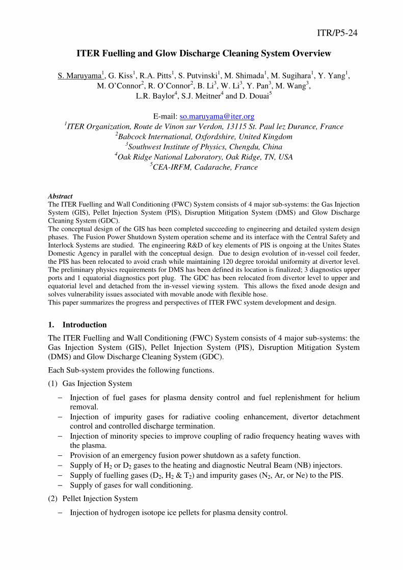
diagnostics). Figure 1 shows the configuration finally adopted and which is now expected to
be stable through the process of port plug procurement.
The PIS has been relocated from divertor port No.6, 12 and 18 to 4, 10 and 16 to avoid a crash
with in-vessel coil feeders while maintaining toroidal uniformity.
In addition to the plasma fuelling parameters and impurity gas injection for radiative cooling
and divertor detachment
control [1], the physics
requirements on DMS
have tentatively defined
for its conceptual design.
Detail will be presented
in the following section.
Number of the system
and their locations are
determined to avoid
localized radiative heat
load to the vicinity of
injection points, which
may exceed acceptable
heat load on the first wall
and lead local melting.
The GDC has been
relocated to upper and
equatorial levels and
fully integrated in the
diagnostics port plugs.
Each sub-system consists of the following.
(1) Gas Injection System
− Upper port level: 4 gas valve boxes (GVB)
Color code: green for upper, blue for equatorial and orange for divertor level
Figure 1 Overall Fuelling and Wall Conditioning System Distribution
− Divertor port level: 6 GVBs distributed toroidally with 60° of separation, and 6 PIS
fuelling GVBs.
− Dedicated manifold for fuel supply to the heating and diagnostic NB injectors.
(2) Pellet Injection System
− Three divertor ports are allocated. Each port is equipped with a PIS cask which can
accommodate 2 injectors.
− Two injectors will be installed for the beginning of machine operations.
− Six injectors will be available for the start of DT plasma operation.
(3) Disruption Mitigation System
− Three locations at upper port level are allocated for Thermal (and electromagnetic load)
Mitigation system (TM) and 1 equatorial port for both TM and Runaway Electron
suppression (RE) systems.
(4) Glow Discharge Cleaning System
− Total of 7 GDC electrodes will be integrated in 3 diagnostics upper port plugs (UPP) and
4 diagnostics equatorial port plugs (EPP).
3. System Design and Development
3.1 Gas Injection System
The GIS Conceptual Design Review (CDR) was successfully completed in 2011 and is now in
the preliminary design
phase. Procurement of the
system will be performed
by the Chinese Domestic
Agency (CN-DA). The GIS
consists principally of the
Gas Fuelling System (GFS),
Gas Delivery System (GDS)
and Fusion Power
Shutdown System (FPSS).
The GFS consists of GVBs
at 4 of the upper ports and 6
divertor ports, with
additional GVBs on the
GDS fuelling manifold for
the PIS (the GVB is
illustrated in Figure 2).
The GFS provides vessel pre-fill and early gas feed during plasma initiation and current ramp-
up, steady state gas supply for non-active plasmas (e.g. hydrogen and helium), injection of
extrinsic impurities and fuel atoms for divertor plasma seeding and detachment control and
adjustment of the main scrape-off layer plasma density.
The GDS provides hydrogenic fuel and impurity gases for pellet production and propellant gas
for pellet acceleration. These gases are provided through dedicated GVBs, which have almost
the same configuration as those used for the GFS. It also provides H2 and/or D2 gases for
heating and diagnostic NB injectors.
Figure 2 Flow diagram in GFS GVB with FPSS
The FPSS provides safety plasma shutdown in the case of an ex-vessel Loss of Coolant
Accident (LOCA) and has 100 % redundancy. It is fully integrated into 2 GVBs at upper port
level and consists of a 1 liter reservoir and safety isolation valves as shown in Figure 2. The
reservoir is filled with 30 kPa·m3 of neon gas, which will be injected within 3 sec by a trigger
signal from the Central Safety System (CSS). Once the FPSS is triggered, disruption is usually
generated, which might damage the in-vessel components. Therefore, it is set up in this way
that CSS shall provide the information to ITER interlock system to actuate the DMS to avoid
additional damages to the ITER components. It should be noted that this mitigation is not a
safety operation. The further detailed study of the FPSS concept, including numerical analysis
of gas injection response and its operational logic and sequence, is on-going as a part of the
preliminary engineering of the GIS [2].
The GFS is now exploring possible use of a digital dosing valve as one of the viable solution
for gas puffing, which has excellent repeatability and stability in throughput control, and is
robust against the high gamma radiation dose and magnetic field in the port cells. This valve
consists of flow nozzles with different sizes and on-off valves, and can provide step-wise flow
control throughout the required flow regime.
3.2 Pellet Injection System
During operation in high
power H-modes, plasma
simulations suggest that gas
puffing from the edge in
ITER will be inefficient for
core fuelling [3]. Pellet
injection, which is capable of
injecting fuel particles into
the confined plasma, is thus
expected to be mandatory for
core fuelling. The PIS
provides core plasma density
control using high field side
(HFS) injection and is being
designed to provide ELM
pacing via low field side
(LFS) pellet introduction. Maximum pellet injection speeds of 300 ms-1
are expected to be
possible with the current HFS and LFS flight tube configuration. To improve the pellet
fuelling efficiency, an elevated injection point near the HFS machine mid-plane in addition to
the lower position is now being explored as shown in Figure 3.
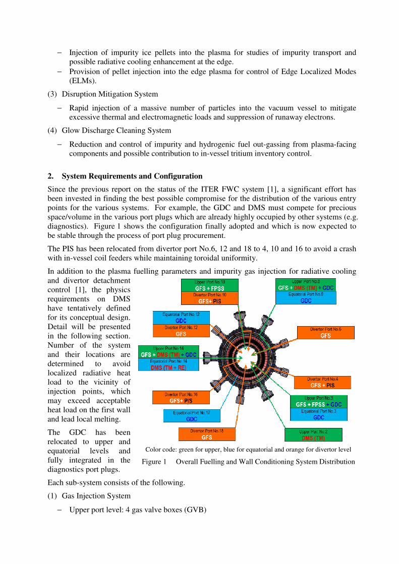
An engineering R&D program is now on-going at the United States Domestic Agency (US-
DA) to develop and demonstrate the key technologies necessary for the ITER pellet injector,
namely a twin screw extruder, pneumatic gas gun pellet accelerator, fuel recirculation,
propellant gas recovery and recirculation and flight tube selector as shown in Figure 4. A
prototype one-fifth ITER scale, twin-screw extruder has been designed and built at the Oak
Ridge National Laboratory (ORNL) which produces a continuous deuterium (D2) extrudate as
the material source for the fuelling and ELM pacing pellets [4]. A propellant recirculate
prototype is now being built and tested at ORNL.
Figure 3 Pellet Flight Tube Layout
Recently an ITER-like LFS
pellet injection line has been
installed on DIII-D near the
X-point, shown in Figure 3,
in addition to the LFS
injector installed on the
machine mid-plane. The
experimental results have
successfully demonstrated
that LFS high frequency
pellets at 60 Hz from both of
the mid-plane and X-point
injection trigger ELMs and
significantly reduce the heat
load to the divertor. Reduced
high-Z and lower Z impurities have been also observed in the plasma core and edge during the
ELM pacing phase [5].
3.3 Disruption Mitigation System
ITER plasmas will operate at
very high stored energy and
plasma current. It is mandatory
for machine protection that the
enormous thermal and
electromagnetic loads and
runaway electrons, which will
be generated during disruptions
of such plasma, be reliably and
effectively mitigated. Physics
studies to define the
requirements for the DMS are
currently running in parallel
with a detailed engineering
assessment of candidate
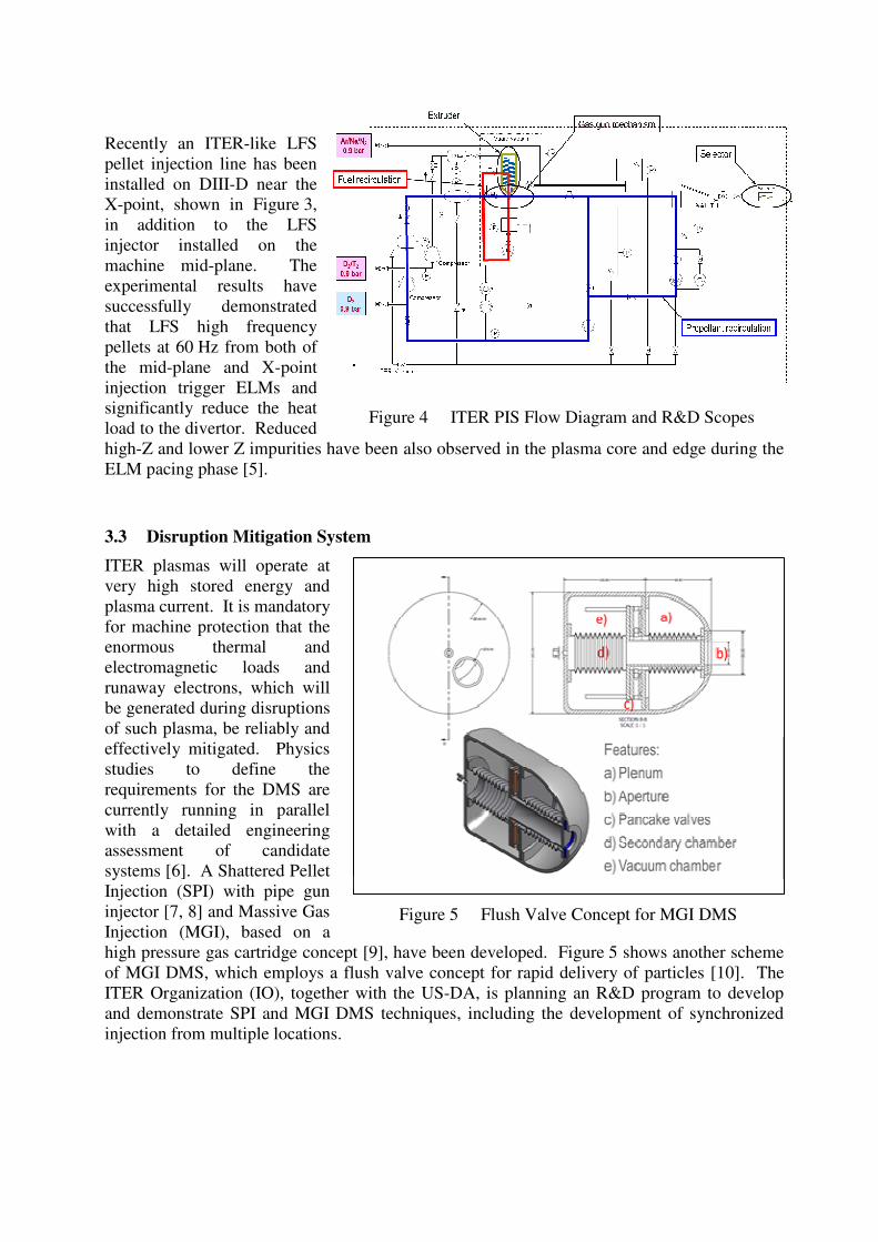
systems [6]. A Shattered Pellet
Injection (SPI) with pipe gun
injector [7, 8] and Massive Gas
Injection (MGI), based on a
high pressure gas cartridge concept [9], have been developed. Figure 5 shows another scheme
of MGI DMS, which employs a flush valve concept for rapid delivery of particles [10]. The
ITER Organization (IO), together with the US-DA, is planning an R&D program to develop
and demonstrate SPI and MGI DMS techniques, including the development of synchronized
injection from multiple locations.
Figure 4 ITER PIS Flow Diagram and R&D Scopes
Figure 5 Flush Valve Concept for MGI DMS
There is a limitation imposed by the ITER vacuum
pumping system on the quantity of gases which can
be introduced by DMS. The limit is determined for
each candidate gas species (see Table 1) by the
vacuum system design and operation, and
additionally for deuterium by the safety requirement
that the accumulated quantity of D2 in torus
cryopumps not exceed the deflagration limit.
The US DA has organized a Disruption Mitigation Workshop in March 2012 to develop the
scope and work plan for the ITER DMS procurement with participants from US, EU and the IO.
Three options, based on compatibility with the ITER DMS schedule and accumulated
technology basis, were selected for near term development plan. ITER will proceed with MGI,
SPI and beryllium shell cartridge DMS options through the preliminary engineering phase. In
parallel with the system design, prototype development is planned for final selection of the
ITER DMS.
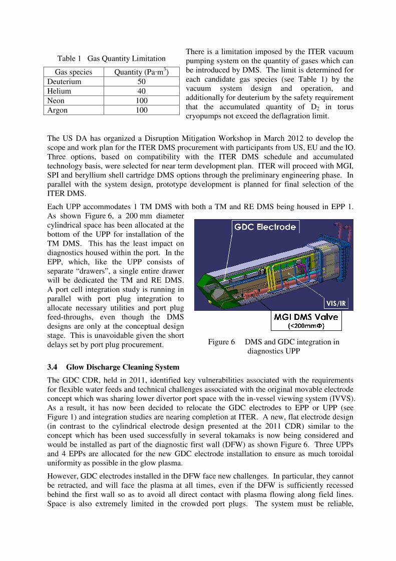
Each UPP accommodates 1 TM DMS with both a TM and RE DMS being housed in EPP 1.
As shown Figure 6, a 200 mm diameter
cylindrical space has been allocated at the
bottom of the UPP for installation of the
TM DMS. This has the least impact on
diagnostics housed within the port. In the
EPP, which, like the UPP consists of
separate “drawers”, a single entire drawer
will be dedicated the TM and RE DMS.
A port cell integration study is running in
parallel with port plug integration to
allocate necessary utilities and port plug
feed-throughs, even though the DMS
designs are only at the conceptual design
stage. This is unavoidable given the short
delays set by port plug procurement.
3.4 Glow Discharge Cleaning System
The GDC CDR, held in 2011, identified key vulnerabilities associated with the requirements
for flexible water feeds and technical challenges associated with the original movable electrode
concept which was sharing lower divertor port space with the in-vessel viewing system (IVVS).
As a result, it has now been decided to relocate the GDC electrodes to EPP or UPP (see
Figure 1) and integration studies are nearing completion at ITER. A new, flat electrode design
(in contrast to the cylindrical electrode design presented at the 2011 CDR) similar to the
concept which has been used successfully in several tokamaks is now being considered and
would be installed as part of the diagnostic first wall (DFW) as shown Figure 6. Three UPPs
and 4 EPPs are allocated for the new GDC electrode installation to ensure as much toroidal
uniformity as possible in the glow plasma.
However, GDC electrodes installed in the DFW face new challenges. In particular, they cannot
be retracted, and will face the plasma at all times, even if the DFW is sufficiently recessed
behind the first wall so as to avoid all direct contact with plasma flowing along field lines.
Space is also extremely limited in the crowded port plugs. The system must be reliable,
Table 1 Gas Quantity Limitation
Gas species Quantity (Pa·m3)
Deuterium 50
Helium 40
Neon 100
Argon 100
Figure 6 DMS and GDC integration in
diagnostics UPP
compact, ensure neutron shielding, be water
cooled, and capable of the application of
bias voltages up to ~1.5 kV.
The IO is now working with CEA/IRFM to
test experimentally the proposed electrode
geometries and to benchmark GDC plasma
measurements made in a test chamber
against simulations using a hybrid
fluid/kinetic plasma code developed at the
Univ. of Toulouse, France. Once
benchmarked, the simulations will be used
to assess the glow plasma uniformity to be
expected on ITER for the GDC electrode
number and location. Meanwhile the
experimental tests will assess the
breakdown efficiency and heat loading of
the proposed electrode concept, including
the effects of recess behind a first wall
surface.
The CN-DA is also performing GDC bench
tests with their facility, in which pressure in
the chamber is controlled to simulate the
ITER condition.
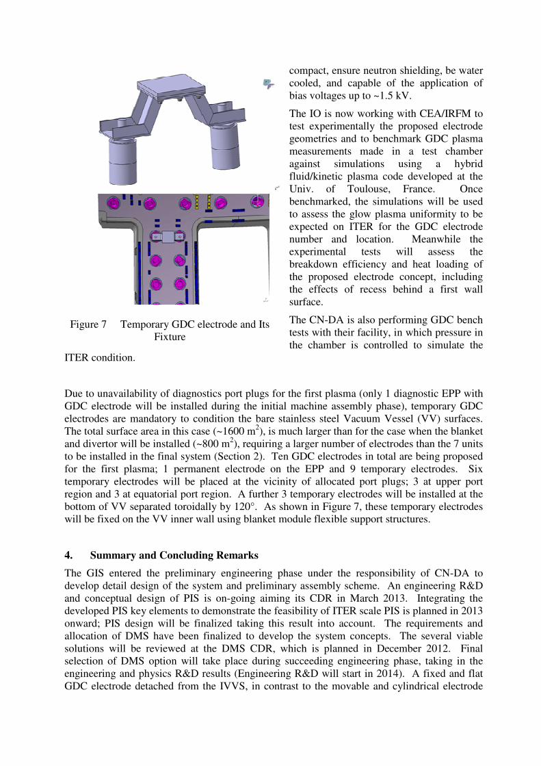
Due to unavailability of diagnostics port plugs for the first plasma (only 1 diagnostic EPP with
GDC electrode will be installed during the initial machine assembly phase), temporary GDC
electrodes are mandatory to condition the bare stainless steel Vacuum Vessel (VV) surfaces.
The total surface area in this case (~1600 m2), is much larger than for the case when the blanket
and divertor will be installed (~800 m2), requiring a larger number of electrodes than the 7 units
to be installed in the final system (Section 2). Ten GDC electrodes in total are being proposed
for the first plasma; 1 permanent electrode on the EPP and 9 temporary electrodes. Six
temporary electrodes will be placed at the vicinity of allocated port plugs; 3 at upper port
region and 3 at equatorial port region. A further 3 temporary electrodes will be installed at the
bottom of VV separated toroidally by 120°. As shown in Figure 7, these temporary electrodes
will be fixed on the VV inner wall using blanket module flexible support structures.
4. Summary and Concluding Remarks
The GIS entered the preliminary engineering phase under the responsibility of CN-DA to
develop detail design of the system and preliminary assembly scheme. An engineering R&D
and conceptual design of PIS is on-going aiming its CDR in March 2013. Integrating the
developed PIS key elements to demonstrate the feasibility of ITER scale PIS is planned in 2013
onward; PIS design will be finalized taking this result into account. The requirements and
allocation of DMS have been finalized to develop the system concepts. The several viable
solutions will be reviewed at the DMS CDR, which is planned in December 2012. Final
selection of DMS option will take place during succeeding engineering phase, taking in the
engineering and physics R&D results (Engineering R&D will start in 2014). A fixed and flat
GDC electrode detached from the IVVS, in contrast to the movable and cylindrical electrode
Figure 7 Temporary GDC electrode and Its
Fixture
presented at the 2011 CDR has been employed as the ITER baseline. This new design together
with the additional scope of temporary electrode design will be presented to the CDR in
November 2012.
Following the GIS, the PIS, DMS and GDC will move ahead to the succeeding engineering
phase in 2013 under the responsibility of the CN and US-DA. The IO will support the DAs
with respect to the system integration, interface control, assembly and commissioning planning.
Acknowledgement
The authors would like to thank members from ITER Organization and Domestic Agencies for
the useful discussion and support of this work. The authors express special thanks to Drs.
Y.H. Kim and M. Glugla for continuous support and encouragement for the conceptual
engineering of ITER fuelling system.
Disclaimer: The views and opinions expressed herein do not necessarily reflect those of the ITER
Organization.
Reference
[1] S. Maruyama et al., ITR/1-28, IAEA FEC 2010, Daejeon.
[2] Y. Yang et al., SOFT 2012, Liege.
[3] A. S. Kukushkin et al., J. N. Mater. 415 (2011) S497.
[4] S. Meitner et al., TOFE 2012, Nashville.
[5] L.R. Baylor, et al., EPS/ICPP 2012, Stockholm.
[6] M. Sugihara, et al., ITR/P1-14, IAEA FEC 2012, San Diiego.
[7] S.K. Combs et al., IEEE Trans. on Plasma Science 38-3 (2010) 400.
[8] N. Commaux et al., Nucl. Fusion 51 (2011) 103001.
[9] S. Putvinski et al., ITR/1-6, IAEA FEC 2010, Daejeon.