37
1 ITER Vacuum Vessel Status and ITER Vacuum Vessel Status and Procurement Procurement IBF, Nice 11 December 2007 Presented by K. Ioki Tokamak Department, ITER Organization

1
ITER Vacuum Vessel Status and ITER Vacuum Vessel Status and Procurement Procurement
IBF, Nice 11 December 2007
Presented by K. IokiTokamak Department, ITER Organization
2
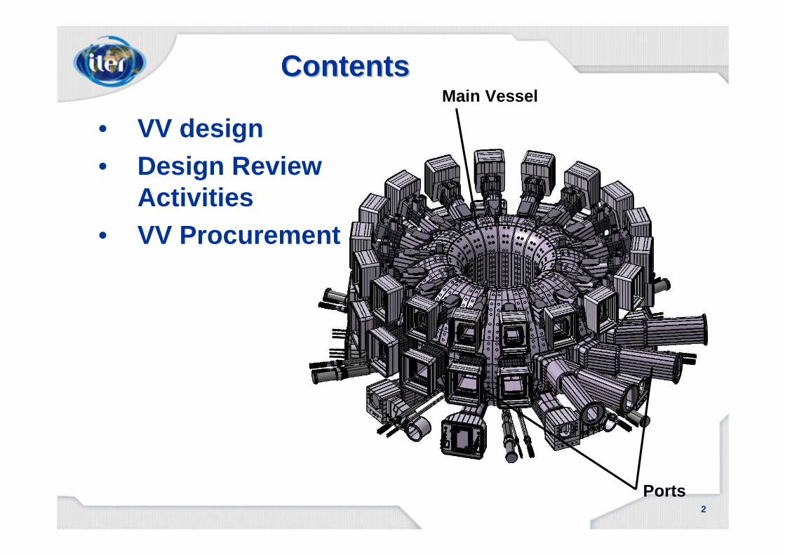
ContentsContents
• VV design• Design Review
Activities• VV Procurement
Main Vessel
Ports
3
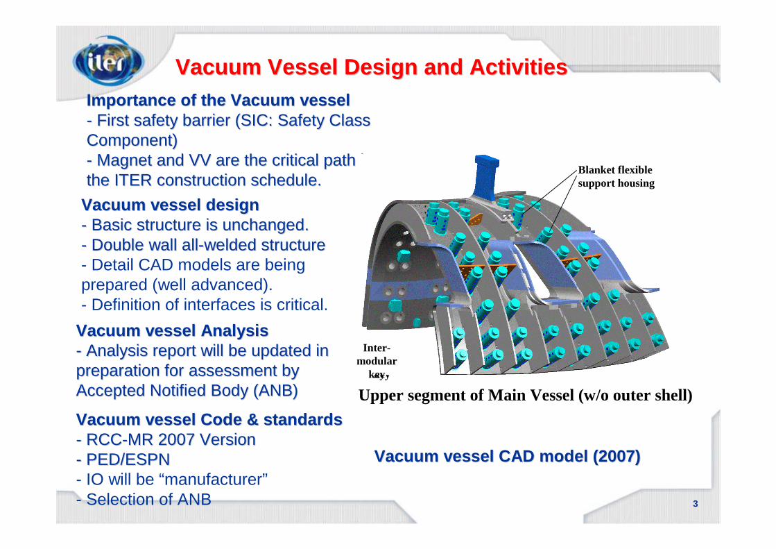
Vacuum vessel Analysis Vacuum vessel Analysis -- Analysis report will be updated in Analysis report will be updated in preparation for assessment by preparation for assessment by Accepted Notified Body (ANB) Accepted Notified Body (ANB)
Vacuum Vessel Design and ActivitiesVacuum Vessel Design and Activities
Vacuum vessel Code & standardsVacuum vessel Code & standards-- RCCRCC--MR 2007 VersionMR 2007 Version-- PED/ESPNPED/ESPN- IO will be “manufacturer”- Selection of ANB
Vacuum vessel CAD model (2007)Vacuum vessel CAD model (2007)
Importance of the Vacuum vessel Importance of the Vacuum vessel -- First safety barrier (SIC: Safety Class First safety barrier (SIC: Safety Class Component)Component)-- Magnet and VV are the critical path in Magnet and VV are the critical path in the ITER construction schedule.the ITER construction schedule.
Vacuum vessel design Vacuum vessel design -- Basic structure is unchanged.Basic structure is unchanged.-- Double wall allDouble wall all--welded structurewelded structure- Detail CAD models are being prepared (well advanced).- Definition of interfaces is critical.
Inter-modular
key
Upper segment of Main Vessel (w/o outer shell)
Blanket flexible support housing
Inter-modular
key
4
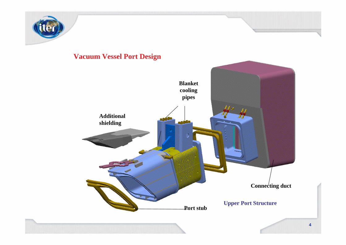
Upper Port StructurePort stub
Connecting duct
Additional shielding
Blanket cooling pipes
Vacuum Vessel Port Design

5
InIn--wall shielding of the Vacuum Vesselwall shielding of the Vacuum Vessel
Function Function -- Neutron shielding.Neutron shielding.-- Ripple mitigationRipple mitigation
Corrosion test is starting Corrosion test is starting -- SCC/Crevice corrosionSCC/Crevice corrosion-- WorkWork--hardened stainless hardened stainless steelsteel-- Galvanic corrosion (mixed Galvanic corrosion (mixed materials)materials)
Ferromagnetic steel plates Ferromagnetic steel plates -- EM forces calculated. EM forces calculated. -- Support design progressing.Support design progressing.
Structure and Materials Structure and Materials -- MultiMulti--plates mechanically assembled.plates mechanically assembled.- Borated steel and Ferritic steel (SS 430)- Eddy currents are minimized in this design.
Optimization for Ripple minimization Optimization for Ripple minimization -- Detail calculation onDetail calculation on--going.going.
-- ProgressingProgressing --
6
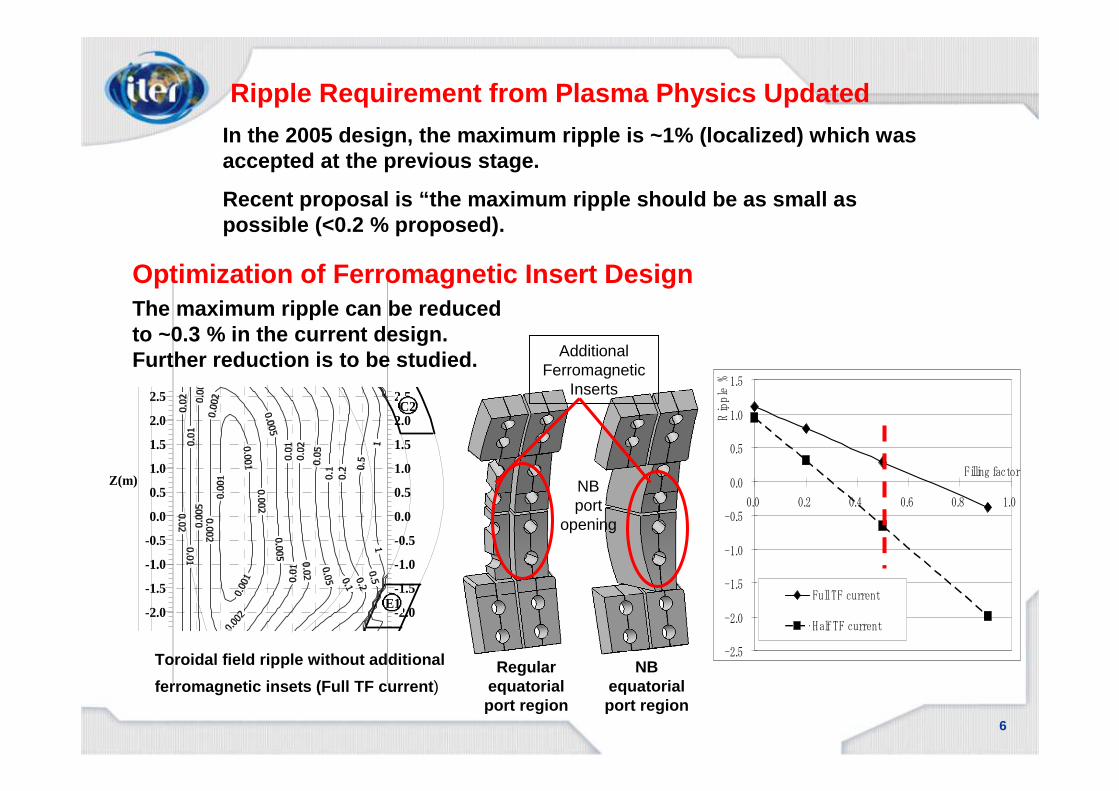
Ripple Requirement from Plasma Physics Updated
-2.5
-2.0
-1.5
-1.0
-0.5
0.0
0.5
1.0
1.5
2.0
2.5
Z(m)
-2.5
-2.0
-1.5
-1.0
-0.5
0.0
0.5
1.0
1.5
2.0
2.5
E1
C2
Toroidal field ripple without additional
ferromagnetic insets (Full TF current )
Additional Ferromagnetic
Inserts
NB port
opening
Regular equatorial port region
NB equatorial port region
-2.5
-2.0
-1.5
-1.0
-0.5
0.0
0.5
1.0
1.5
0.0 0.2 0.4 0.6 0.8 1.0
Filling factor
Ripple %
Full TF current
Half TF current
In the 2005 design, the maximum ripple is ~1% (loca lized) which was accepted at the previous stage.
Recent proposal is “the maximum ripple should be as small as possible (<0.2 % proposed).
Optimization of Ferromagnetic Insert DesignThe maximum ripple can be reduced to ~0.3 % in the current design. Further reduction is to be studied.

7
Measurement of outgassing rate (JA)
LPT on UHV surfaceVacuum vessel sector
Leak Testing (Proposed)
Helium enclosure, could
also be flexible oven
filled to 1 bar
He
Calibrated
leak
RGA
Outgassing rate seems to be acceptable based on the test result.
- Low impurity liquid penetrant (Dye) should be selected.
- Careful cleaning after LPT is required.
Leak rate <10-9 Pam3/s is a target value to be achieved. This is challenging for a large complicate component.
For the VV system 1 x 10⁻⁷ Pam3/s

8
200 C
Liquid Penetrant Outgassing Test for UHV use
Measurement of outgassing rate (JA)

9
Design Development of NB Port liners (On-going)
- Fabrication technology
- Mitigate high peak stresses.
- RH compatible structure
NB ports
Inside view of HNB port HNB liner structure
High heat flux element the HNB liner structure

10
removable flat strip
Exploded view of option A (Stiffeners of the strip plate are not shown)
M52 Bolts(under vacuum)
plug inner lip
Port Flange Design
VV outer lip
Port plug
- Lip seal -
“compliant” plate part of the gasket flange
Double metallic gasket seals
M52standard boltsor superbolts
Port plug
Vacuum / He feeding pipe for local and continuousleak checking
0.05 MPa tracer gas
- Gasket -
11
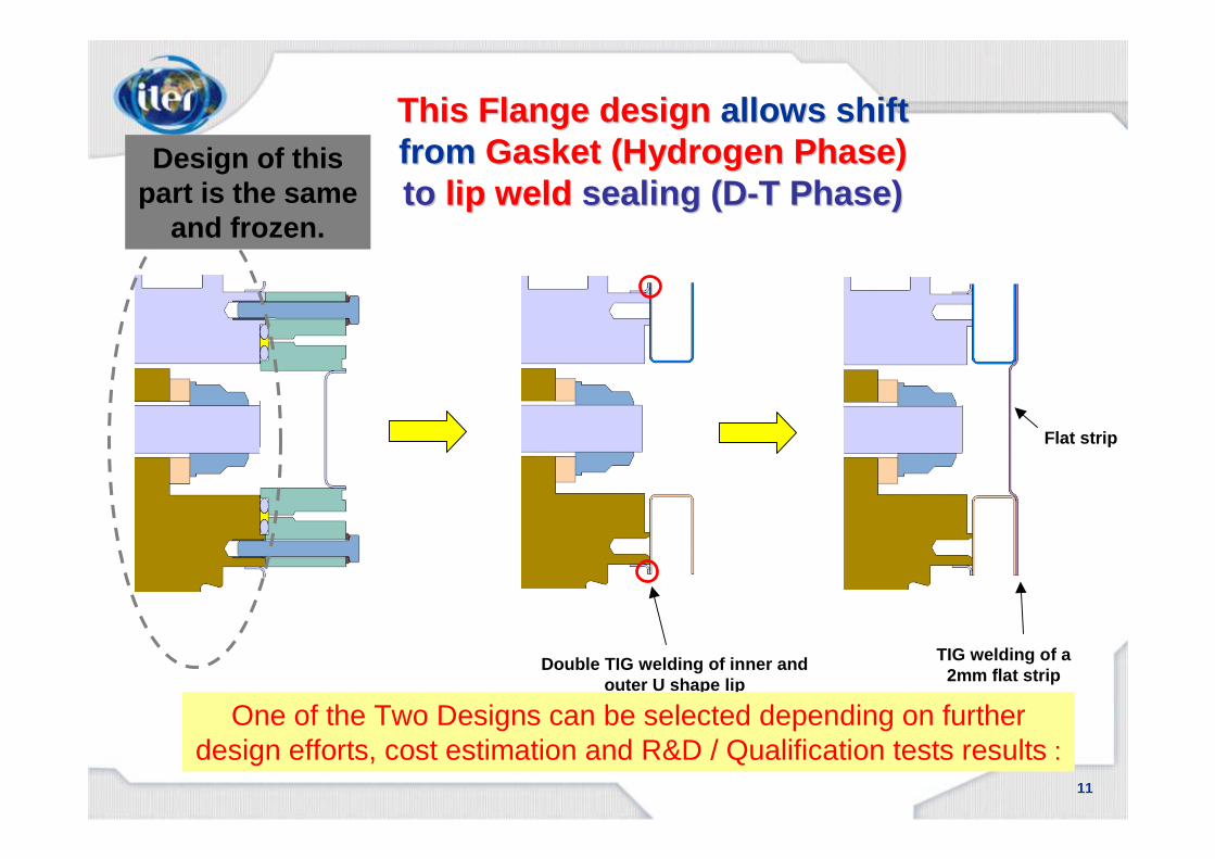
Flat strip
This Flange designThis Flange design allows shift allows shift from from Gasket (Hydrogen Phase) Gasket (Hydrogen Phase) toto lip weld lip weld sealing (Dsealing (D --T Phase)T Phase)
TIG welding of a 2mm flat strip
Double TIG welding of inner and outer U shape lip
One of the Two Designs can be selected depending on further design efforts, cost estimation and R&D / Qualification tests results :
Design of this part is the same
and frozen.

12
R&D: Full scale Equatorial flange mock-up
Simplified mock-upQualification of sealing
EP : 2090 x 2542
150
230
Test campaign*(k€)
400250Upper flange
680450Equatorial flange
Total cost (k€)Manufacture (k€)Mock-up
(*) Includes the baking and insulation equipment

13
Partial VV Sector Mock-up: PS2 (Curved Section) Fabrication
Welding joint connection between PS1 (straight section) and PS2 (Inboard upper curved section)
Partial Full-scale VV Sector FabricationPartial VV Sector Fabrication was completed.
- Dimensional accuracy is mostly within the required (or target) tolerances.
- Fabrication methods to be further optimized.
- EB welding was used for welding between the inner shell and keys and flexible support housings
Automatic NG TIG welding on the outer shell of the PS1-PS2 joint
Partial Full-scale VV Sector Fabrication (EU)
14
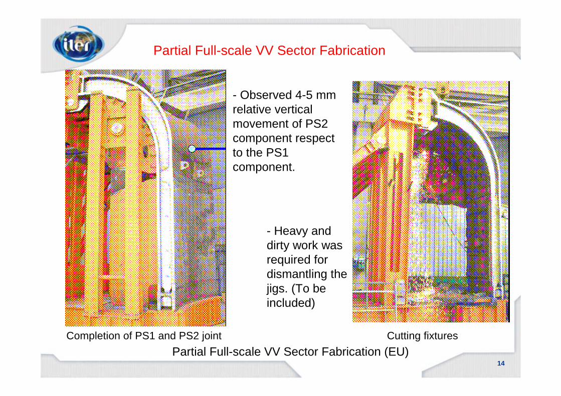
Cutting fixtures
- Observed 4-5 mm relative vertical movement of PS2 component respect to the PS1 component.
- Heavy and dirty work was required for dismantling the jigs. (To be included)
Partial Full-scale VV Sector Fabrication
Completion of PS1 and PS2 joint
Partial Full-scale VV Sector Fabrication (EU)

15
Summary: Fabrication tolerance- Poloidal movements of the PS2 respect to the PS1 was observed (~0.2°PS1 / PS2 deflection)- All Outer Shell surface is within the acceptance fabrication tolerances (±10 mm)- Some of the Inner Shell Housing positions (radial ~ +6mm) are out of the target fabrication tolerances: (radi al ±5 mm, poloidal ±3 mm). This can be improved in the future .- All Inner Shell surface is within the target fabric ation tolerances (±10 mm)
A poloidal movement (X-Z plane) of the PS2 was observed respect to the PS1, due to the jig dismantling (Laser Tracker measurement). The red line (see Left) shows this PS2 movement (amplified 10 times).
Partial Full-scale VV Sector Fabrication
Result of Partial Full-scale VV Sector Fabrication (EU)
16
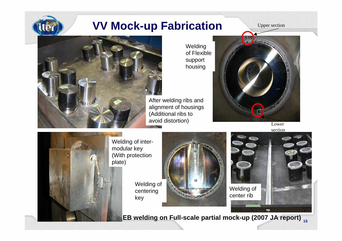
After welding ribs and alignment of housings(Additional ribs to avoid distortion)
Welding of inter-modular key (With protection plate)
Upper section
Lower section
EB welding on Full-scale partial mock-up (2007 JA r eport)
Welding of centering key
Welding of center rib
Welding of Flexible support housing
VV Mock-up Fabrication

17
Full-scale partial mock-up (Left: Plasma side, Righ t: Outer shell side) (2007 JA report)
VV Mock-up Fabrication

18
ITER VV Field Joint Welding R&DITER VV Field Joint Welding R&D
Outer Shell Welding Machine Outer Shell Welding Head
After fabrication, sectors A and B were welded together at the field joint on the center of the ports. This involved welding splice plates using the automatic NG-TIG process and inspecting the joint by the UT method.
Full Scale Sector Model (JA)

19
ITER VV Field Joint Welding R&DITER VV Field Joint Welding R&D
Inner Shell Splice Plate Inner Shell Welding Machine
Full Scale Sector Model (JA)

20
The lower port stub region (especially vertical gussets) is to be reinforced.
Study of Increased Vertical and Horizontal Loads

21
The VV horizontal displacement during VDE is increased. 10 mm ����15 mm
The gaps between VV/VVTS and VVTS/TFC is marginally acceptable. To be studied further.
Study of Increased Vertical and Horizontal Loads

22
Damper shall have a function of the actuator to position the VV horizontally with accuracy of 1mm.
VV Supporting System
High vertical load will be acceptable when it is tran sient.

23
80
1150
400
1150
VV Supporting System
Toroidal support (for VV center positioning)
(1) Adequate flexibility (spring constant) in the to roidal direction is required to mitigate the reaction force
(2) Active position control mechanism is under consi deration.

24
To improve the plasma vertical stability
- Wider copper cladding area
- To Minimize cut-outs
- To increase the copper coating thickness and achieve better material quality
Triangular Support Design Improvement

25
Vessels and Interfaces Activities Vessels and Interfaces Activities -- by Design Review by Design Review WGsWGs 20062006--20072007--
WG1
WG2
WG5
WG6
- ELM control coil proposal- Plasma vertical stability improvement- Ripple minimization
- Tritium inventory, Dust removal - VV ESPN categorization- VV ISI requirement
- Blanket manifold - RH 3 requirement - VV support improvement- Blanket flexible support improvement- Dome shape cryostat / Independent support structur e
- Enlargement of the DNB port opening
- Blanket manifold - RH 3 requirement - VV support improvement- Blanket flexible support improvement- Dome shape cryostat / Independent support structur e
Physics
Safety
Vessels
Heating
26
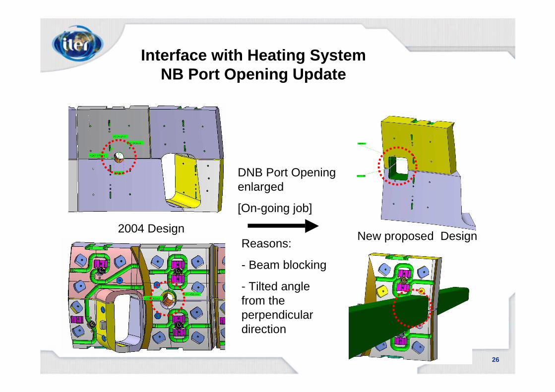
Interface with Heating System NB Port Opening Update
DNB Port Opening enlarged
[On-going job]
2004 DesignNew proposed Design
Reasons:
- Beam blocking
- Tilted angle from the perpendicular direction

27
NB Port Opening Update (VV Port #4)
Design update of the VV structure in the DNB port area

28
Interfaces with Blanket Attachments
Intermodular key
Flexible support
4 Interfaces remain the same
- Hydraulic connection
- Current straps
- Keys
- Flexible supports
No Change!!
Current strapHydraulic Connection
29
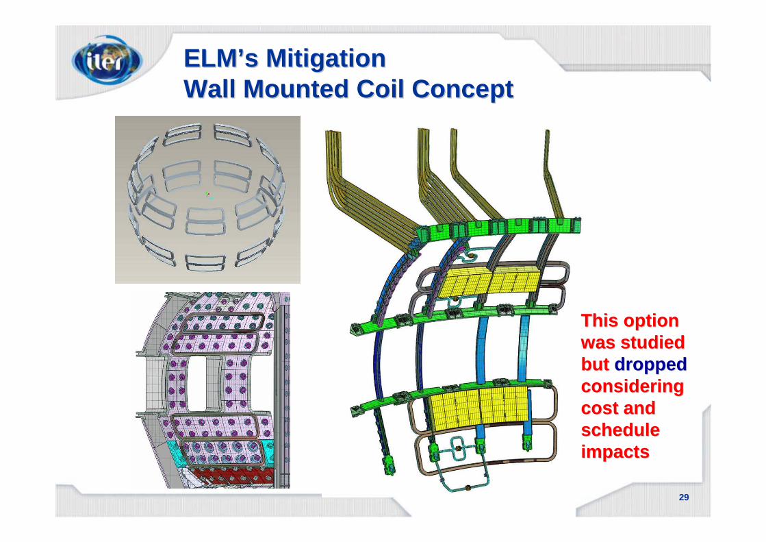
ELMELM’’ss MitigationMitigationWall Mounted Coil ConceptWall Mounted Coil Concept
This option This option was studied was studied but but droppeddroppedcconsideringonsideringcost and cost and schedule schedule impactsimpacts

30
mid+topport coils
ELMELM’’ss Mitigation Mitigation –– Port Coil ConceptPort Coil Concept
This optionThis optionis to be further is to be further studied.studied.
31
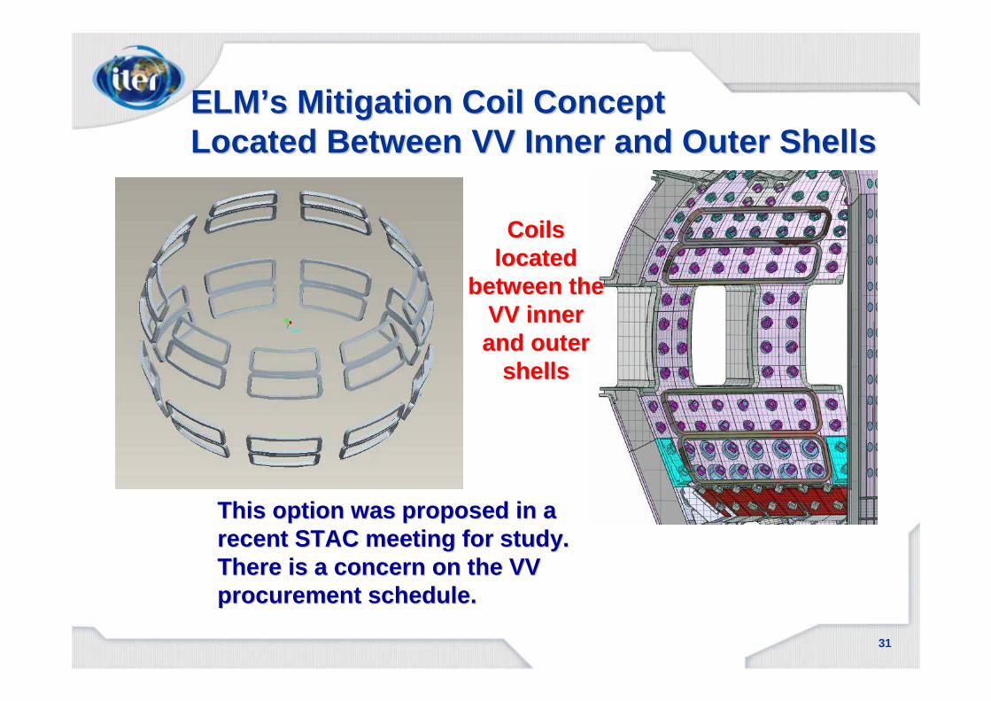
ELMELM’’ss Mitigation Coil ConceptMitigation Coil ConceptLocated Between VV Inner and Outer ShellsLocated Between VV Inner and Outer Shells
This option was proposed in a This option was proposed in a recent STAC meeting for study.recent STAC meeting for study.There is a concern on the VV There is a concern on the VV procurement schedule.procurement schedule.
Coils Coils located located
between the between the VV inner VV inner and outer and outer
shellsshells

32
VV Procurement ScheduleVV Procurement Schedule• It is clear that the critical path activities for the project are the procurements
of the VV, the TF coils, and the buildings.• The VV Procurement Arrangement (PA) is scheduled to be issued mid-
2008. To meet this schedule the following dates must be met.
• VV Design Frozen – Sept 2007 “Design options should be eliminated (for the VV)”
– Blanket Attachment – Blanket Manifolds– Lower Ports (new proposal for blanket piping)– Divertor Support (Updated design)– ELM Control Coils (new proposal)– NB Port (Size, angle, location)– VV Port Flange Design– Triangular Support Modifications– VV Gravity Supports
• VV Interfaces Frozen – Nov 2007– Blanket– Cooling system– Diagnostics– NB - Safety– Building - Plasma– Cryostat - TS

33
Triangular support
Structures for lifting
Divertorsupport rail
VV gravity support
VV Procurement ScheduleVV Procurement Schedule
Apr-08PA* Complete
June-08PA* Signed
July-083D Models Complete
Dec 08 KOJune 09 EU
Contract Awarded
July 08 KOSept 08 EU
Call for Tender
Dec-07Code Selection: RCC-MR 2007
Nov-07Interfaces Frozen
Sept-07Design Frozen
Date1.5 Vacuum Vessel
PA*: Procurement Arrangement between IO and DasPA*: Procurement Arrangement between IO and Das
-- Design and interface freeze dates are critical Design and interface freeze dates are critical to allow the VV Pto allow the VV P 3333rocurement to proceed on rocurement to proceed on schedule.schedule.-- These dates may drive blanket and These dates may drive blanket and divertordivertordesign activities.design activities.

34
Vacuum Vessel Manufacturing Scheme (w/o Consortium)
ManufacturerIO
ManufacturerIO
Fabrication:- Welding- Materials- NDT- Test (pressure)- Etc.
Notified Body:
Check design, Manufacture,and issue the statement of
conformity
Design/ESR:- Strength, - Seismic, - hazard- Etc.
Dossier Manufacturer (IO):
Declaration of Conformity Global
Conformity
Contract
Subcontractor –Control of fabrication
Subcontractor –Control of fabrication
Equatorial and Lower
PortsKO
Equatorial and Lower
PortsKO
UpperPorts
RF
UpperPorts
RF
VVIW Shield
IN(non structural)
VVIW Shield
IN(non structural)
FJ WeldingIO
FJ WeldingIO
Main VV20%-KO
Main VV20%-KO
Main VV80%-EU
Main VV80%-EU
35
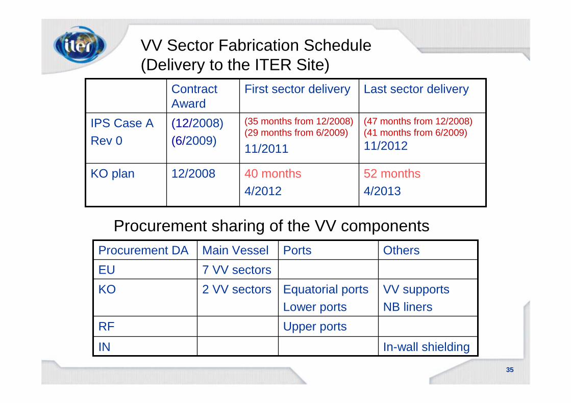
52 months4/2013
40 months 4/2012
12/2008KO plan
(47 months from 12/2008)(41 months from 6/2009)
11/2012
(35 months from 12/2008) (29 months from 6/2009)
11/2011
(12/2008)(6/2009)
IPS Case A Rev 0
Last sector deliveryFirst sector deliveryContract Award
VV Sector Fabrication Schedule (Delivery to the ITER Site)
In-wall shielding
VV supportsNB liners
Others
IN
Upper portsRF
Equatorial portsLower ports
2 VV sectorsKO
7 VV sectorsEU
PortsMain VesselProcurement DA
Procurement sharing of the VV components

36
5360Main vessel and ports Grand total
1858Ports(316 L(N) IG, 304 L)
3502Main vessel total
159Water
54Additional shielding
1679In-wall shielding(1% and 2% Borated steel and 430)
1611Main Vessel(316 L(N) IG)
Weight (ton)
Materials for the VV fabrication
37
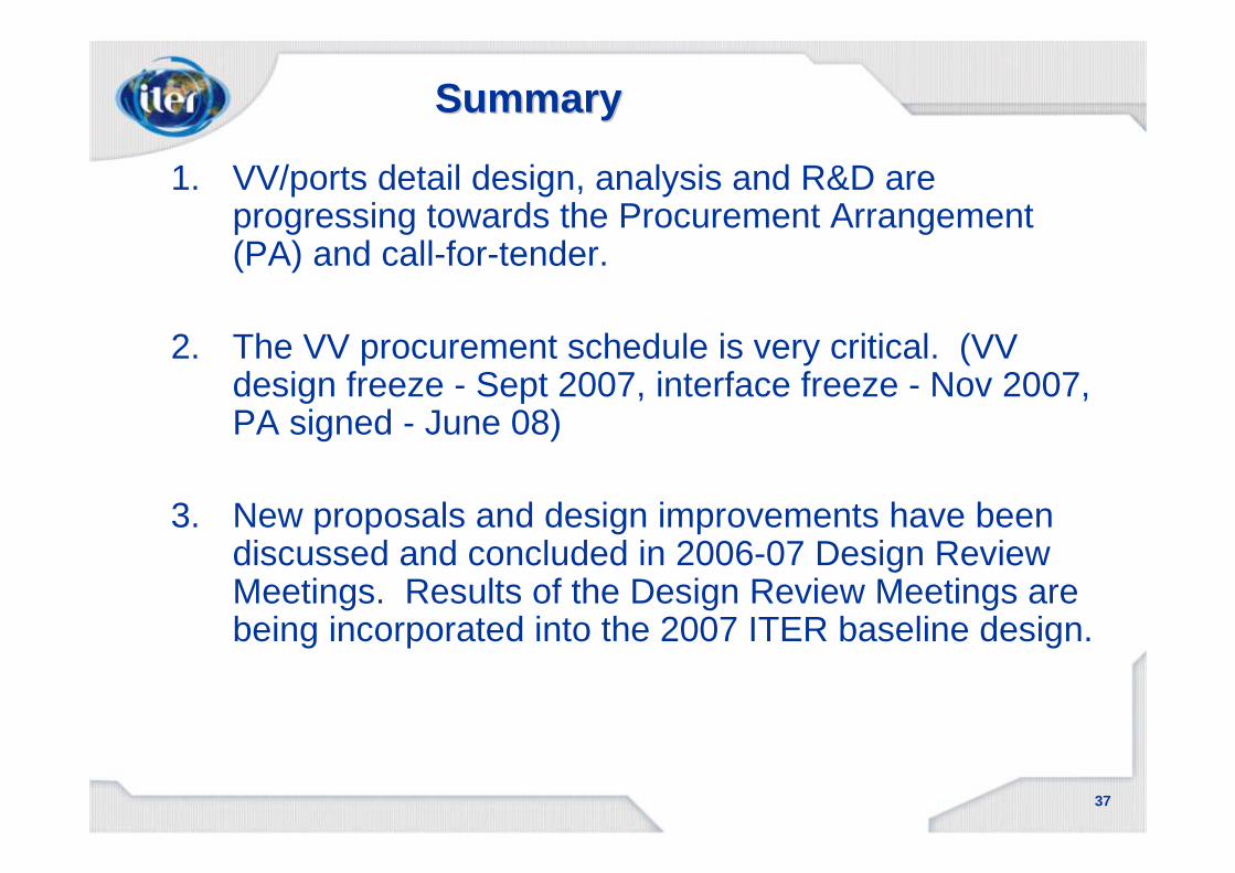
SummarySummary
1. VV/ports detail design, analysis and R&D are progressing towards the Procurement Arrangement (PA) and call-for-tender.
2. The VV procurement schedule is very critical. (VV design freeze - Sept 2007, interface freeze - Nov 2007, PA signed - June 08)
3. New proposals and design improvements have been discussed and concluded in 2006-07 Design Review Meetings. Results of the Design Review Meetings are being incorporated into the 2007 ITER baseline design.


