• PHOEL Iterative Demodulation and Decoding for Protected Satellite Communications VOLUME 15, NUMBER 1, 2005 LINCOLN LABORATORY JOURNAL 79 Iterative Demodulation and Decoding for Protected Satellite Communications Wayne G. Phoel ■ Military satellite communications (Milsatcom) systems use frequency hopping over a wide bandwidth to provide protection from hostile jamming, interception, and detection. These systems are being challenged to transport more information at higher rates, among smaller and more mobile terminals, with little or no increase in allocated bandwidth. Meeting these challenges requires advanced bandwidth-efficient and power-efficient signaling techniques. This article describes an approach to error-control coding and modulation that can help achieve the requirements of future Milsatcom systems. The receiver in this approach iterates between demodulation and decoding, which enables near-coherent performance with minimal reference symbol overhead. Also, the decoding process is augmented so that, in the presence of jamming, the receiver estimates the jammer state and combines information appropriately from different hops. T from jamming, inter- ception, and detection complicates the military satellite communications (Milsatcom) scenario significantly beyond the challenges encountered in commercial wireless communications systems. In spite of this fact, the defense community aims to duplicate in military environments the increased capabilities of commercial wireless devices available in the public do- main. While there is some truth to the notion that pro- tection comes at the cost of capacity, in general we can do much to provide bandwidth-efficient and power-ef- ficient protected communications to the military end user. In particular, we can take advantage of recent ad- vances in iterative decoding techniques to attain the de- sired level of protection with efficient use of bandwidth and power resources. The scenario considered in this article concentrates on the jamming resistance of a frequency-hopping spread-spectrum system. Our approach uses frequency hopping combined with error-control coding to miti- gate the effects of the jamming. In addition, by pass- ing information on the reliability of symbols from the decoder back to the demodulator, and iterating several times, we can achieve near-coherent performance and also account for the effects of the jammer. To resist hostile jamming, interception, and detec- tion, protected Milsatcom systems communicate at high frequencies. The Milstar, Advanced EHF, and next-generation Transformational Satellite Communi- cations (TSAT) systems use EHF and SHF frequen- cies at 44 GHz and 20 GHz, respectively. These high frequencies enable the use of small, highly directional antennas to minimize emissions away from the desired signal direction. These frequencies also come with rela- tively large bandwidths, which enable spread-spectrum techniques to hide the communications signal further as well as protect it from hostile attempts at disruption. In frequency-hopping spread-spectrum systems, the transmitter hops from center frequency to center fre- quency according to a pseudo-random sequence, dwell-
Transcript
• PHOELIterative Demodulation and Decoding for Protected Satellite Communications
VOLUME 15, NUMBER 1, 2005 LINCOLN LABORATORY JOURNAL 79
Iterative Demodulation and Decoding for Protected Satellite CommunicationsWayne G. Phoel
■ Military satellite communications (Milsatcom) systems use frequency hopping over a wide bandwidth to provide protection from hostile jamming, interception, and detection. These systems are being challenged to transport more information at higher rates, among smaller and more mobile terminals, with little or no increase in allocated bandwidth. Meeting these challenges requires advanced bandwidth-efficient and power-efficient signaling techniques. This article describes an approach to error-control coding and modulation that can help achieve the requirements of future Milsatcom systems. The receiver in this approach iterates between demodulation and decoding, which enables near-coherent performance with minimal reference symbol overhead. Also, the decoding process is augmented so that, in the presence of jamming, the receiver estimates the jammer state and combines information appropriately from different hops.
T from jamming, inter-ception, and detection complicates the military satellite communications (Milsatcom) scenario
significantly beyond the challenges encountered in commercial wireless communications systems. In spite of this fact, the defense community aims to duplicate in military environments the increased capabilities of commercial wireless devices available in the public do-main. While there is some truth to the notion that pro-tection comes at the cost of capacity, in general we can do much to provide bandwidth-efficient and power-ef-ficient protected communications to the military end user. In particular, we can take advantage of recent ad-vances in iterative decoding techniques to attain the de-sired level of protection with efficient use of bandwidth and power resources.
The scenario considered in this article concentrates on the jamming resistance of a frequency-hopping spread-spectrum system. Our approach uses frequency hopping combined with error-control coding to miti-
gate the effects of the jamming. In addition, by pass-ing information on the reliability of symbols from the decoder back to the demodulator, and iterating several times, we can achieve near-coherent performance and also account for the effects of the jammer.
To resist hostile jamming, interception, and detec-tion, protected Milsatcom systems communicate at high frequencies. The Milstar, Advanced EHF, and next-generation Transformational Satellite Communi-cations (TSAT) systems use EHF and SHF frequen-cies at 44 GHz and 20 GHz, respectively. These high frequencies enable the use of small, highly directional antennas to minimize emissions away from the desired signal direction. These frequencies also come with rela-tively large bandwidths, which enable spread-spectrum techniques to hide the communications signal further as well as protect it from hostile attempts at disruption.
In frequency-hopping spread-spectrum systems, the transmitter hops from center frequency to center fre-quency according to a pseudo-random sequence, dwell-
• PHOELIterative Demodulation and Decoding for Protected Satellite Communications
80 LINCOLN LABORATORY JOURNAL VOLUME 15, NUMBER 1, 2005
F R E QU E N C Y HO PPI N G F OR PRO T E C T I O N F ROM J A M M I N G
allows the system to spread the communi-cations signal over a wide band-width while keeping the instanta-neous signal bandwidth processed by the transmitter and receiver relatively small. Both the trans-mitter and receiver compute the same pseudo-random sequence to determine on which frequency to communicate at a specific time. Typically, the transmitter re-mains at the center frequency for a fixed-length dwell interval and then hops to the next frequency. As a result, the term hop is often used to refer to the period the sig-nal stays at one frequency.
The objective of the jammer is to disrupt the communications signal. The jammer, however, does not have unlimited transmit power. Therefore, its goal is to transmit a signal that will cause the most degradation of the de-sired signal, subject to its power constraint. The most common jammer strategy is a partial-band white-noise jammer. In this strat-egy, the jammer continuously transmits a Gaussian-distributed pseudo-random noise sequence with bandwidth a fraction ρ of the total bandwidth. Due to the power constraint, a narrow band-width (small ρ) corresponds to a
large amount of energy concen-trated in the communications signal instantaneous bandwidth. But a small ρ also decreases the likelihood that a frequency used to communicate gets jammed. Similarly, spreading the jamming signal over a wide bandwidth di-lutes the jammer power and de-creases the energy in a given sig-nal band in order to increase the chances of degrading the com-munications. Therefore, from the perspective of a protected system, we want to force a jammer to op-erate over a large portion of the bandwidth, limiting the effective-ness of each hit by the jammer.
ing at each frequency for a fixed interval. The period of time during which the transmitted signal remains at that frequency is referred to as the dwell interval. The larger the total bandwidth used for hopping, the more difficult it is for the jammer to disrupt the communi-cations. The sidebar entitled “Frequency Hopping for Protection from Jamming” provides more explanation of the concept of frequency hopping in a spread-spec-trum system.
Iterative decoding, often referred to as turbo decod-ing, is becoming increasingly popular in communica-tion system designs. Although iterative techniques had been used in systems before the advent of turbo codes, none of those techniques provided the dramatic gains that result from coupling the turbo-code design with the a posteriori probability (APP) soft-output algorithm used in the decoding process [1]. Since the introduc-tion of turbo codes, iterative receiver designs have been applied to topics such as equalization, multiple user
detection, and space-time coding [2]. The majority of research on such iterative receivers, however, assumes perfect knowledge of the side information (i.e., informa-tion that is not the ultimate goal of the receiver, but is used to decode the received signal, including parameters such as carrier phase, and signal and interference levels) necessary for the turbo decoder to achieve the channel capacity-approaching performance now expected of er-ror-control codes.
In this article, we apply iterative demodulation and decoding to the slow frequency-hopping scenario in or-der to provide protection at low signal-to-interference ratios (the term slow frequency hopping means that more than one channel symbol is transmitted in each dwell interval). At the same time, we investigate techniques to estimate the relevant side information, such as the ran-dom carrier phase shift seen from hop to hop and the received signal reliability, including detection of jam-ming in dwell intervals.
• PHOELIterative Demodulation and Decoding for Protected Satellite Communications
VOLUME 15, NUMBER 1, 2005 LINCOLN LABORATORY JOURNAL 81
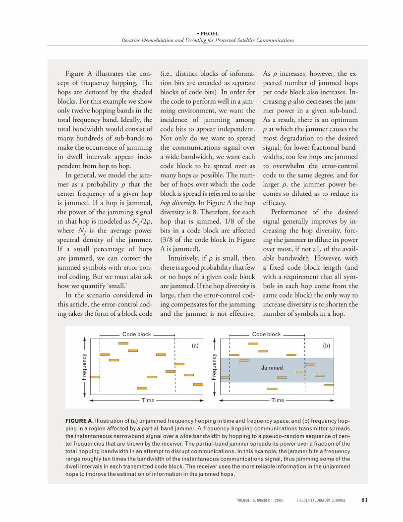
Figure A illustrates the con-cept of frequency hopping. The hops are denoted by the shaded blocks. For this example we show only twelve hopping bands in the total frequency band. Ideally, the total bandwidth would consist of many hundreds of sub-bands to make the occurrence of jamming in dwell intervals appear inde-pendent from hop to hop.
In general, we model the jam-mer as a probability ρ that the center frequency of a given hop is jammed. If a hop is jammed, the power of the jamming signal in that hop is modeled as NJ /2ρ, where NJ is the average power spectral density of the jammer. If a small percentage of hops are jammed, we can correct the jammed symbols with error-con-trol coding. But we must also ask how we quantify ‘small.’
In the scenario considered in this article, the error-control cod-ing takes the form of a block code
FIGURE A. Illustration of (a) unjammed frequency hopping in time and frequency space, and (b) frequency hop-ping in a region affected by a partial-band jammer. A frequency-hopping communications transmitter spreads the instantaneous narrowband signal over a wide bandwidth by hopping to a pseudo-random sequence of cen-ter frequencies that are known by the receiver. The partial-band jammer spreads its power over a fraction of the total hopping bandwidth in an attempt to disrupt communications. In this example, the jammer hits a frequency range roughly ten times the bandwidth of the instantaneous communications signal, thus jamming some of the dwell intervals in each transmitted code block. The receiver uses the more reliable information in the unjammed hops to improve the estimation of information in the jammed hops.
(i.e., distinct blocks of informa-tion bits are encoded as separate blocks of code bits). In order for the code to perform well in a jam-ming environment, we want the incidence of jamming among code bits to appear independent. Not only do we want to spread the communications signal over a wide bandwidth, we want each code block to be spread over as many hops as possible. The num-ber of hops over which the code block is spread is referred to as the hop diversity. In Figure A the hop diversity is 8. Therefore, for each hop that is jammed, 1/8 of the bits in a code block are affected (3/8 of the code block in Figure A is jammed).
Intuitively, if ρ is small, then there is a good probability that few or no hops of a given code block are jammed. If the hop diversity is large, then the error-control cod-ing compensates for the jamming and the jammer is not effective.
As ρ increases, however, the ex-pected number of jammed hops per code block also increases. In-creasing ρ also decreases the jam-mer power in a given sub-band. As a result, there is an optimum ρ at which the jammer causes the most degradation to the desired signal; for lower fractional band-widths, too few hops are jammed to overwhelm the error-control code to the same degree, and for larger ρ, the jammer power be-comes so diluted as to reduce its efficacy.
Performance of the desired signal generally improves by in-creasing the hop diversity, forc-ing the jammer to dilute its power over most, if not all, of the avail-able bandwidth. However, with a fixed code block length (and with a requirement that all sym-bols in each hop come from the same code block) the only way to increase diversity is to shorten the number of symbols in a hop.
Jammed
Code block
Freq
uenc
y
Time
Code block
Freq
uenc
y
Time
(a) (b)
• PHOELIterative Demodulation and Decoding for Protected Satellite Communications
82 LINCOLN LABORATORY JOURNAL VOLUME 15, NUMBER 1, 2005
System Goals and Approach
In frequency-hopping systems, we cannot ensure car-rier phase continuity at the boundaries of dwell inter-vals, and consequently we must reacquire the phase for each hop. For the purposes of this work, we assume the phase offset is constant for the duration of a dwell in-terval but it changes randomly from hop to hop. We might demodulate coherently by estimating the phase offset from known reference symbols transmitted in each dwell. This technique can be inefficient for short dwell intervals because the number of reference symbols required for an explicit estimate of the phase may result in excessive overhead, thus affecting both the power- and bandwidth-efficiencies. More typically, noncoher-ent schemes such as frequency-shift keying (FSK) or differential phase-shift keying (DPSK) are used to com-municate with the unknown phase shift in each dwell. FSK, however, is much less spectrally efficient than we would like, and DPSK conventionally suffers by about 2 to 3 dB in required signal-to-noise ratio, compared to a coherent receiver.
In the frequency-hopping system considered here, we concentrate on DPSK with iterative demodulation and decoding. The number of reference symbols in this sce-nario is limited to one per dwell. As mentioned above, conventional demodulation of DPSK incurs a loss of approximately 2 dB. However, recent success in itera-tively decoding interleaved concatenated codes shows excellent performance with a simple combination of a convolutional code, a pseudo-random permutation, and differential modulation [3]. This configuration can be considered a serially concatenated convolutional code (SCCC) in which the differential modulation acts as the inner code of the serial concatenation. Even when we are faced with an unknown phase offset, nearly co-herent performance is often attainable [4, 5].
Of the iterative receiver techniques discussed in the literature, we focus on that described by M. Peleg, S. Shamai, and S. Galán, in which the continuously dis-tributed random phase offset is approximated by a quantized phase [4]. An expanded trellis is then used to search over all possible sequences, assuming the now-limited number of possible phase offsets. The result is a joint estimation of the data and the carrier phase. Other techniques for dealing with unknown phase offset in
an iterative fashion include averaging over the uniform random phase (resulting in the introduction of a Bes-sel function) in computing branch metrics in a trellis-based demodulator [5, 6], and iterative explicit phase estimation [7–9]. We note that averaging over the phase distribution results in degraded performance, compared to the receiver considered here, which provides nearly coherent performance in a straightforward manner.
For the scenario considered in this article, we limit the code block length to 2048 code bits (i.e., 1024 in-formation bits assuming a rate-1/2 code) and require all symbols in a particular dwell to come from the same code block. Such a requirement limits the memory and processing needed at both transmitter and receiver. (Note: Internet protocol [IP] packets have an over-head of at least 480 bits, so that although a 1024-in-formation-bit block may seem large, it is reasonable in a packet-based system.) The error-control code inserts redundancy into the transmitted sequence to enable er-ror correction and/or detection. A rate-1/2 code doubles the number of bits used to represent the information se-quence. For hops of short duration (e.g., one reference symbol and sixteen data symbols) we find that, with the technique considered here, there is significant loss with respect to coherent performance. However, hav-ing more symbols per hop translates to fewer hops over which a code block is spread, which compromises pro-tection. Consequently, when jamming is introduced to the system model, there is a trade-off between protec-tion from jamming and coherent demodulation. In that case, we find that having shorter dwells (and therefore more hops per block) results in significantly better per-formance in the worst-case partial-band jamming than having longer dwells.
The performance of turbo codes, or parallel concat-enated convolutional codes (PCCC), in jamming is dis-cussed by J.H. Kang and W.E. Stark [10, 11], wherein the trade-off between hop diversity and the duration of the hop was studied for coherent binary PSK (BPSK) [10] and M-ary FSK [11], with and without initial knowledge of whether a dwell interval is jammed. Those results assume that the receiver knows the jam-mer and noise power levels in order to scale the inputs to the APP decoders correctly. The decoding algorithm is sensitive to the scaling of the channel values; incor-rect scaling may result in the failure of the iterative al-
• PHOELIterative Demodulation and Decoding for Protected Satellite Communications
VOLUME 15, NUMBER 1, 2005 LINCOLN LABORATORY JOURNAL 83
Two similar approaches have been reported in the lit-erature. Each explicitly estimates the noise variance in a dwell to scale channel values. In one approach, a clus-tering algorithm is used to distinguish jammed symbols from non-jammed symbols, and the noise variance is estimated separately for each group [16]. Iterating with the decoding is not performed. The other approach de-scribes iterative noise variance estimation in combina-tion with a PCCC and with a convolutional code [17]. There the variance estimates are improved throughout the iterations, based on the a priori information gener-ated by the decoder. The performance presented here is comparable to that for the turbo code [17], but requires a less complex receiver.
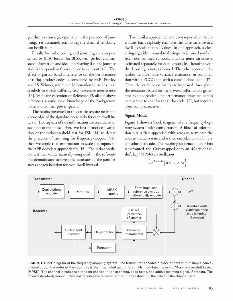
Signal Model
Figure 1 shows a block diagram of the frequency-hop-ping system under consideration. A block of informa-tion bits is first appended with zeros to terminate the code in the zero state and is then encoded with a binary convolutional code. The resulting sequence of code bits is permuted and Gray-mapped onto an M-ary phase-shift key (MPSK) constellation
e m Mj m M2 0π / .≤ <{ }
FIGURE 1. Block diagram of the frequency-hopping system. The transmitter encodes a block of data with a simple convo-lutional code. The order of the code bits is then permuted and differentially modulated by using M-ary phase-shift keying (MPSK). The channel introduces a random phase shift on each hop, adds noise, and adds a jamming signal, if present. The receiver iteratively demodulates and decodes the received signal, jointly estimating the data and the channel state.
Convolutionalencoder
Soft-outputdemodulatorDe-permuter
Permuter
Soft-outputdecoder
Detect presenceof jammer
MPSK mappingPermuter
Form hops, add reference symbol,
differentially encodeej k
Additive white Gaussian noise plus jamming,
if present
φ
Transmitter
Receiver
Channel
gorithm to converge, especially in the presence of jam-ming. Yet accurately estimating the channel reliability can be difficult.
Results for turbo coding and jamming are also pre-sented by M.A. Jordan for BPSK with perfect channel state information and ideal interleaving (i.e., the jammer state is independent from symbol to symbol) [12]. The effect of partial-band interference on the performance of turbo product codes is considered by M.B. Pursley and J.S. Skinner, where side information is used to erase symbols in dwells suffering from excessive interference [13]. With the exception of Reference 13, all the above references assume some knowledge of the background noise and jammer power spectra.
The results presented in this article require no initial knowledge of the signal-to-noise ratio for each dwell in-terval. Two aspects of side information are considered in addition to the phase offset. We first introduce a varia-tion of the ratio-threshold test for FSK [14] to detect the presence of jamming for frequency-hopped PSK; then we apply that information to scale the inputs to the APP decoders appropriately [15]. The ratio-thresh-old test uses values naturally computed in the soft-out-put demodulator to revise the estimates of the jammer states at each iteration for each dwell interval.
• PHOELIterative Demodulation and Decoding for Protected Satellite Communications
84 LINCOLN LABORATORY JOURNAL VOLUME 15, NUMBER 1, 2005
The permutation is fixed but computed according to a pseudo-random process. The randomness of the permu-tation effectively distributes the information contained in each bit throughout the code word, improving the er-ror-correcting capability of the code. This improvement is dramatic when the decoder iterates between demodu-lation and decoding. The permutation also decorrelates the presence of the jammer in consecutive bit estimates as seen by the outer convolutional code. Gray mapping assigns a sequence of log2M bits to one of M constella-tion points such that only one bit differs in sequences mapped to adjacent symbols. For example, a valid Gray mapping of all length-two binary sequences to a quater-nary constellation maps (0, 0) to 1, (0, 1) to j, (1, 0) to –j, and (1, 1) to –1.
The single complex value used to represent the M bits for transmission over the channel is called a chan-nel symbol. The sequence of MPSK channel symbols is parsed into equal-length subsequences, which form the signals to be transmitted in the dwell intervals. Each in-terval begins with an arbitrarily chosen reference sym-bol known at both the transmitter and receiver. The data-bearing channel symbols form the remainder of the transmission for the dwell. Let L be the number of channel symbols transmitted in each dwell interval. If we use a discrete-time baseband system model, the lth channel symbol transmitted in the kth dwell is given by
x x uk l k l k l, , , ,= −1
where uk, l is the lth Gray-coded M-ary symbol prior to differential encoding, and
x ekj m M
,( ) /
02 12∈ { }+ π
is deterministic. This combination of convolutional coding with
pseudo-random permutation and differential modu-lation is essentially an SCCC in the context of a slow frequency-hopping system. The SCCC consists of two constituent codes: the outer binary convolutional code and the inner differential modulation (the differential MPSK can be represented as an M-ary convolutional code). For the results presented here, we consider only M = 4, but it is straightforward to extend the technique to other values of M.
Each dwell interval is assumed to be transmitted at a frequency chosen according to a pseudo-random se-quence known at both the transmitter and the receiver. In our baseband model, the only evidence of the fre-quency hopping is an independent phase offset for each hop and the independence of the jamming among dif-ferent hops. The phase offset is assumed to be constant for the duration of a dwell and varies randomly from in-terval to interval according to a random variable distrib-uted uniformly between 0 and 2π radians. The received signal is also corrupted by thermal additive white Gauss-ian noise (AWGN) and, in the presence of partial-band jamming, an additional AWGN term representing the jamming signal. The corresponding received signal can be written as
y A x e z wk l k k lj
k l k k lk
, , , , ,= + +φ ν where Ak is the gain of the data in the received signal in dwell interval k, φk is the phase offset for dwell k, zk, l represents the complex-valued background noise with two-sided power spectral density N0/2, νk is a Bernoulli random variable taking the value 1 if partial-band jam-ming is corrupting the hop and 0 if not, and wk, l is the jamming signal with average two-sided power spectral density NJ /2.
The jammer is characterized by the fraction ρ of the band that is jammed. We model this as the probability ρ that a particular hop is jammed (i.e., νk = 1 with prob-ability ρ), where we assume that if a hop is jammed, the full duration and bandwidth of that hop is jammed. Therefore, the power spectral density of the jammer, when present, is NJ /2ρ.
Iterative Receiver
The demodulator uses a soft-output trellis-based algo-rithm based on APP decoding, and operating in the log domain. The appendix entitled “Turbo Decoding and the APP Algorithm” provides a more detailed de-scription of APP decoding. Since the carrier phase is unknown, we approximate the continuously distribut-ed random phase as a random variable with a discrete distribution [4, 18]. The number of phases in the dis-crete distribution is set to 8M, thus requiring a trellis with 8M states (rather than only M states in the case of known phase) for demodulation. The state of the sig-nal at a specific time is given by the current phase of
• PHOELIterative Demodulation and Decoding for Protected Satellite Communications
VOLUME 15, NUMBER 1, 2005 LINCOLN LABORATORY JOURNAL 85
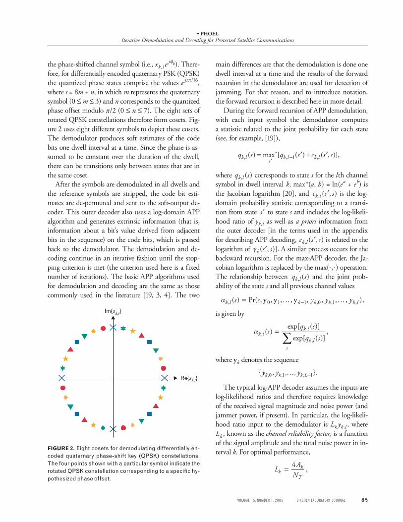
the phase-shifted channel symbol (i.e., xk, l ejφk). There-
fore, for differentially encoded quaternary PSK (QPSK) the quantized phase states comprise the values e jsπ /16, where s = 8m + n, in which m represents the quaternary symbol (0 ≤ m ≤ 3) and n corresponds to the quantized phase offset modulo π/2 (0 ≤ n ≤ 7). The eight sets of rotated QPSK constellations therefore form cosets. Fig-ure 2 uses eight different symbols to depict these cosets. The demodulator produces soft estimates of the code bits one dwell interval at a time. Since the phase is as-sumed to be constant over the duration of the dwell, there can be transitions only between states that are in the same coset.
After the symbols are demodulated in all dwells and the reference symbols are stripped, the code bit esti-mates are de-permuted and sent to the soft-output de-coder. This outer decoder also uses a log-domain APP algorithm and generates extrinsic information (that is, information about a bit’s value derived from adjacent bits in the sequence) on the code bits, which is passed back to the demodulator. The demodulation and de-coding continue in an iterative fashion until the stop-ping criterion is met (the criterion used here is a fixed number of iterations). The basic APP algorithms used for demodulation and decoding are the same as those commonly used in the literature [19, 3, 4]. The two
main differences are that the demodulation is done one dwell interval at a time and the results of the forward recursion in the demodulator are used for detection of jamming. For that reason, and to introduce notation, the forward recursion is described here in more detail.
During the forward recursion of APP demodulation, with each input symbol the demodulator computes a statistic related to the joint probability for each state (see, for example, [19]),
q s q s c s sk l
sk l k l,
*, ,( ) max [ ( ) ( , )],= ′ + ′
′−1
where q sk l, ( ) corresponds to state s for the lth channel symbol in dwell interval k, max*(a, b) = ln(ea + eb) is the Jacobian logarithm [20], and c s sk l, ( , )′ is the log-domain probability statistic corresponding to a transi-tion from state ′s to state s and includes the log-likeli-hood ratio of yk,l as well as a priori information from the outer decoder [in the terms used in the appendix for describing APP decoding, c s sk l, ( , )′ is related to the logarithm of γ k s s( , )′ ]. A similar process occurs for the backward recursion. For the max-APP decoder, the Ja-cobian logarithm is replaced by the max(˙,˙) operation. The relationship between q sk l, ( ) and the joint prob-ability of the state s and all previous channel values
αk l k k k k ls s y y y, , , ,( ) Pr( , , , , , , , , ) ,= … …−y y y0 1 1 0 1
is given by
αk lk l
k ls
sq s
q s,
,
,
( )exp[ ( )]
exp[ ( )],=
∑
where yk denotes the sequence
{ , , , }., , ,y y yk k k L0 1 1… −
The typical log-APP decoder assumes the inputs are log-likelihood ratios and therefore requires knowledge of the received signal magnitude and noise power (and jammer power, if present). In particular, the log-likeli-hood ratio input to the demodulator is Lk yk,l , where Lk , known as the channel reliability factor, is a function of the signal amplitude and the total noise power in in-terval k. For optimal performance,
L
ANk
k
T= 4
,
FIGURE 2. Eight cosets for demodulating differentially en-coded quaternary phase-shift key (QPSK) constellations. The four points shown with a particular symbol indicate the rotated QPSK constellation corresponding to a specific hy-pothesized phase offset.
Im{xk,l}
Re{xk,l}
• PHOELIterative Demodulation and Decoding for Protected Satellite Communications
86 LINCOLN LABORATORY JOURNAL VOLUME 15, NUMBER 1, 2005
where
N N NT k J= +0 ν ρ/ .
Consequently, the magnitude of the desired component of the log-likelihood ratio is proportional to the signal-to-noise ratio in the dwell. When a jamming signal is present in a dwell interval, the optimal input to the de-modulator is LJ yk,l , where LJ = 4A/(N0 + NJ/ρ), and we assume Ak = A for all hops; in the absence of jam-ming, the channel value is scaled by LN = 4A/N0. If the input is a log-likelihood ratio, the output will also be a log-likelihood ratio and can be passed to the outer decoder, but with the a priori information removed.
Performance in Additive White Gaussian Noise with No Jamming
This first set of simulation results illustrates how the it-erative receiver provides significant gains as the number of iterations increases. For all results presented here, the block size is limited to 1022 information bits (plus two terminating bits). The convolutional encoder is non-re-cursive, has memory 2 and rate 1/2, and uses the gener-ating polynomial specified in octal form as (7, 5). Fig-ure 3 shows a diagram of the convolutional encoder. An s-random interleaver of length 2048 is used to permute the code bits before they are modulated with differen-tially encoded QPSK.
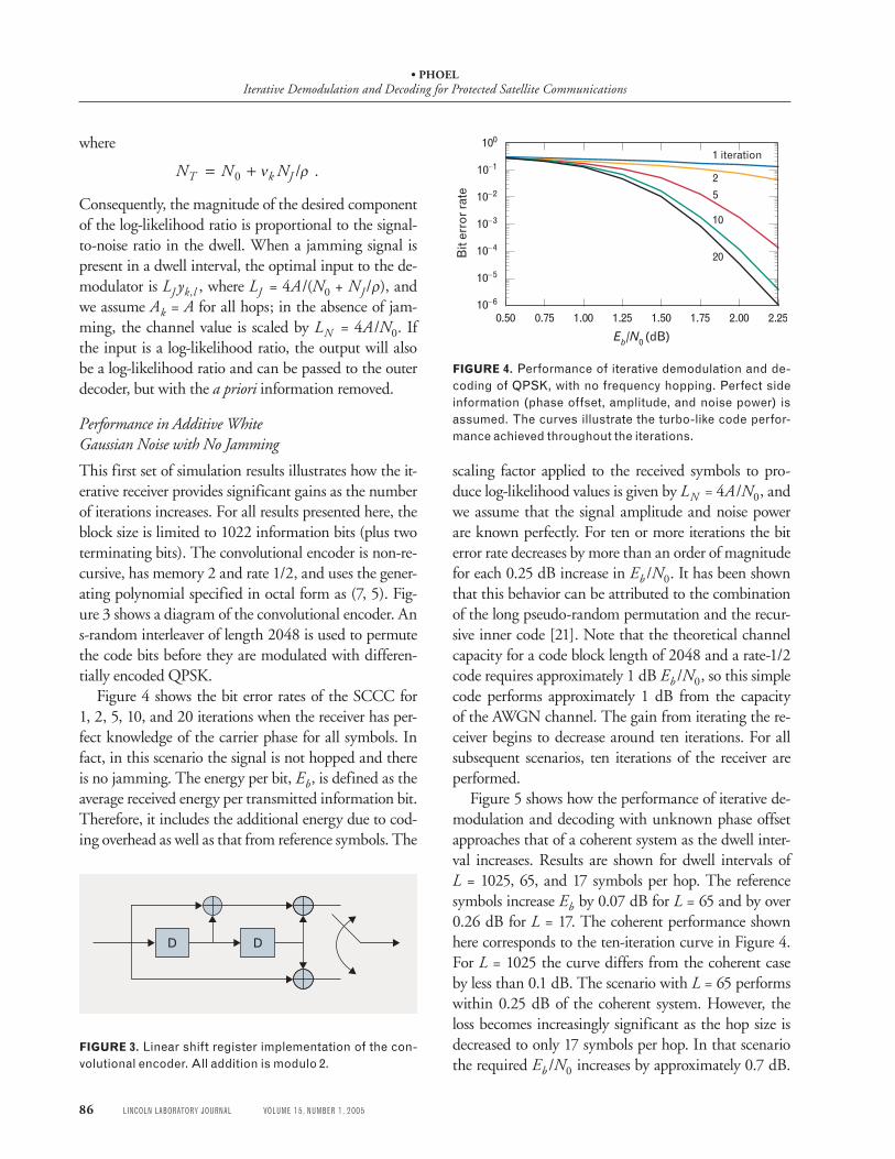
Figure 4 shows the bit error rates of the SCCC for 1, 2, 5, 10, and 20 iterations when the receiver has per-fect knowledge of the carrier phase for all symbols. In fact, in this scenario the signal is not hopped and there is no jamming. The energy per bit, Eb, is defined as the average received energy per transmitted information bit. Therefore, it includes the additional energy due to cod-ing overhead as well as that from reference symbols. The
scaling factor applied to the received symbols to pro-duce log-likelihood values is given by LN = 4A/N0, and we assume that the signal amplitude and noise power are known perfectly. For ten or more iterations the bit error rate decreases by more than an order of magnitude for each 0.25 dB increase in Eb /N0. It has been shown that this behavior can be attributed to the combination of the long pseudo-random permutation and the recur-sive inner code [21]. Note that the theoretical channel capacity for a code block length of 2048 and a rate-1/2 code requires approximately 1 dB Eb /N0, so this simple code performs approximately 1 dB from the capacity of the AWGN channel. The gain from iterating the re-ceiver begins to decrease around ten iterations. For all subsequent scenarios, ten iterations of the receiver are performed.
Figure 5 shows how the performance of iterative de-modulation and decoding with unknown phase offset approaches that of a coherent system as the dwell inter-val increases. Results are shown for dwell intervals of L = 1025, 65, and 17 symbols per hop. The reference symbols increase Eb by 0.07 dB for L = 65 and by over 0.26 dB for L = 17. The coherent performance shown here corresponds to the ten-iteration curve in Figure 4. For L = 1025 the curve differs from the coherent case by less than 0.1 dB. The scenario with L = 65 performs within 0.25 dB of the coherent system. However, the loss becomes increasingly significant as the hop size is decreased to only 17 symbols per hop. In that scenario the required Eb /N0 increases by approximately 0.7 dB.
FIGURE 3. Linear shift register implementation of the con-volutional encoder. All addition is modulo 2.
D D
FIGURE 4. Performance of iterative demodulation and de-coding of QPSK, with no frequency hopping. Perfect side information (phase offset, amplitude, and noise power) is assumed. The curves illustrate the turbo-like code perfor-mance achieved throughout the iterations.
0.50 0.75 1.25 1.75 2.251.00 1.50 2.00
10–4
10–6
10–5
10–3
10–2
10–1
100
Eb/N0 (dB)
Bit
erro
r rat
e
1 iteration
2
5
10
20
• PHOELIterative Demodulation and Decoding for Protected Satellite Communications
VOLUME 15, NUMBER 1, 2005 LINCOLN LABORATORY JOURNAL 87
(Note that this increase in required Eb /N0 includes the energy in the additional reference symbols.)
Clearly, in the absence of partial-band jamming, long dwell intervals are preferable to shorter dwells for the coding and modulation considered here. In addition to increasing the energy in reference symbols, the shorter dwells provide less information about the phase offset and therefore do not approach coherent performance as closely as do the longer dwells.
Performance in Jamming with Knowledge of the Jammer State
In this section we present simulation results that illus-trate the effect of partial-band white-noise jamming on the performance of the system. As described above, the partial-band jammer is modeled as a probability ρ that a dwell interval is jammed, and the jammer power is NJ /ρ in such an interval. For the simulation of jam-ming, Eb /2NJ is varied with Eb /N0 fixed at 10 dB. Also, the energy in the reference symbols is included when we compute Eb for the figures.
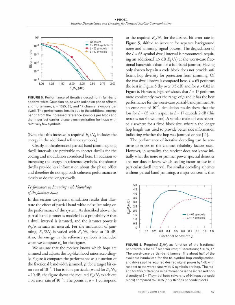
We assume that the receiver knows which hops are jammed and adjusts the log-likelihood ratios according-ly. Figure 6 compares the performance as a function of the fractional bandwidth jammed, ρ, for a target bit er-ror rate of 10–4. That is, for a particular ρ and for Eb /N0 = 10 dB, the figure shows the required Eb /NJ to achieve a bit error rate of 10–4. The points at ρ = 1 correspond
to the required Eb /N0 for the desired bit error rate in Figure 5, shifted to account for separate background noise and jamming signal powers. The degradation of the L = 65 symbol dwell interval is pronounced, requir-ing an additional 1.5 dB Eb /NJ at the worst-case frac-tional bandwidth than for a full-band jammer. Having only sixteen hops in a code block does not provide suf-ficient hop diversity for protection from jamming. Of the two dwell intervals compared here, L = 65 performs the best in Figure 5 (by over 0.5 dB) and for ρ > 0.82 in Figure 6. However, Figure 6 shows that L = 17 performs more consistently over the range of ρ and it has the best performance for the worst-case partial-band jammer. At an error rate of 10–5, simulation results show that the loss for L = 65 with respect to L = 17 exceeds 2 dB (this result is not shown here). A similar trade-off was report-ed elsewhere for a fixed block size, wherein the longer hop length was used to provide better side information indicating whether the hop was jammed or not [11].
The performance of iterative decoding can be sen-sitive to errors in the channel reliability factors used. However, in actuality, the receiver does not know ini-tially what the noise or jammer power spectral densities are, nor does it know which scaling factor to use in a particular dwell interval. For similar decoding schemes without partial-band jamming, a major concern is that
FIGURE 5. Performance of iterative decoding in full-band additive white Gaussian noise with unknown phase offsets and no jammer; L = 1025, 65, and 17 channel symbols per dwell. The performance loss is due to the additional energy per bit from the increased reference symbols per block and the imperfect carrier phase synchronization for hops with relatively few symbols.
FIGURE 6. Required Eb/NJ as function of the fractional bandwidth ρ for 10–4 bit error rate; 10 iterations; L = 65, 17. The worst-case partial-band jammer fills about half of the available bandwidth for the 65-symbol-hop configuration, and drives up the required desired signal power by 1 dB with respect to the worst case with 17 symbols per hop. The rea-son for this difference in performance is the increased hop diversity of L = 17 symbol hops (diversity of 64 hops per code block) compared to L = 65 (only 16 hops per code block).
• PHOELIterative Demodulation and Decoding for Protected Satellite Communications
88 LINCOLN LABORATORY JOURNAL VOLUME 15, NUMBER 1, 2005
the channel symbols and extrinsic information are scaled appropriately between decoders. The desired performance can be obtained by setting LN so that it is optimal at the target error rate. Yet with the presence of partial-band jamming we not only need to ensure that the a priori information and the channel symbols are weighted correctly, but we must also weight bits from dwells containing jamming in the appropriate propor-tion to those without jamming. Of course, first we need to identify those symbols which are jammed and those which are not.
Ratio-Threshold Test for Phase-Shift Keying
The technique considered here is based on the ratio-threshold test for FSK introduced by A.J. Viterbi [14]. For FSK, this test compares the two largest outputs of the envelope detectors to determine whether a received symbol contains excessive interference. The largest de-tector output is assumed to contain the desired signal plus noise and jamming, if present. The second largest output is intended to represent the interference level. If the ratio of the largest value to the second largest value is greater than some predetermined threshold, then we conclude that no significant interference is present. If the ratio is less than the threshold, then we decide that the signal is dominated by interference and we declare that jamming is present.
One of the keys to Viterbi’s test is that the statistics being compared are from orthogonal filters. Unfortu-nately, because of the spectral efficiency of our system, we do not have orthogonal filters to generate indepen-dent statistics. To apply a ratio-threshold test for PSK, we make use of the expanded trellis used to demodu-late the differentially encoded signal. At the end of the forward recursion for dwell interval k, the log-domain routine outputs the joint statistic for each state qk,L–1(s). In general, the trellis states corresponding to the quan-tized phase that is closest to the true phase offset will produce the greatest joint probabilities and therefore the largest values for qk,L–1(s). In addition, the quantized phase that is halfway between adjacent phases from the maximizing coset will contain a greater proportion of the jamming signal. For QPSK, this is a shift of π /4 radians. No output of the demodulator can be assumed to contain only noise.
Whereas the ratio-threshold test for FSK is per-
formed on individual channel symbols, this version for PSK detects jamming over a whole hop. We define
s m nk∗ ∗ ∗= +8
as the state that maximizes qk,L–1(s). The important parameter here is n*, which specifies the coset with the maximum joint probability. Therefore, the coset having the greatest proportion of jamming is specified by
˜ ( )modn n= +∗ 4 8
and the state used for comparison with sk∗ is given by
˜ arg max ( ) .: ˜
,s q sks n n
k L==
−1
Then the statistics we wish to compare to detect jam-ming in dwell k are q sk L k, ( )−
∗1 and q sk L k, (˜ )−1 . Left
unchanged, q sk L k, ( )−∗
1 and q sk L k, (˜ )−1 are correlated because of two components: the presence of the signal component and the a priori information from the previ-ous iteration.
Decision Statistic
To start, we consider the first iteration of the decoder. Since the receiver has no initial knowledge of the state of the jamming in any of the dwells, Lk is initialized to be LN for all k. (Forming a ratio of the two statistics helps alleviate the effects of incorrectly scaling the sym-bols containing jamming.) Let q ik
∗( ) and ˜ ( )q ik denote the signal and jamming statistics for the ith iteration, respectively. If the path through the trellis for ˜ ( )qk 0 corresponds to the correct code sequence, then
˜ ( ) Re ,/, ,q e x yk
jk l k l
l
L
0 4
0
≥ { }− ∗
=∑ π
where here the superscript * denotes the complex con-jugate and the inequality is due to the max* operation. (Consequently, with max-APP decoding, if the path is correct, this expression becomes an equality.) If the cor-responding path through the trellis is not the correct code word then this is a looser bound and the inequal-ity still holds. The term in the summation in the above equation can be rewritten as
22
Re Im ( ., , , , ,x y x z wk l k l k l k l k k l∗ ∗{ } + +{ }[ ]ν
Similarly, we determine the lower bound of qk∗( )0 as
• PHOELIterative Demodulation and Decoding for Protected Satellite Communications
VOLUME 15, NUMBER 1, 2005 LINCOLN LABORATORY JOURNAL 89
q x yk k l k l
l
L∗ ∗
=
≥ { }∑( ) Re ,, ,00
if that path corresponds to the correct code word. As the iterations progress, neglecting the a priori informa-tion, the bound becomes tighter. Therefore, we can rea-sonably make the following approximation:
2 0 0
0
˜ ( ) ( ) Im ( ) ,, , ,q q x z wk k k l k l k k ll
L
− ≈ +{ }∗ ∗
=∑ ν
which no longer contains a component due to the de-sired signal. Note that for larger values of M, this ap-proach—while still valid—is more complicated and suffers from degraded performance.
In later iterations we need to remove the a priori in-formation. This extrinsic information helps choose the right sequence through the trellis for detecting the jam-mer, but this additional information should not be in-cluded in the statistic used in the ratio test (otherwise, as the extrinsic information grows it will dominate all other terms and the ratio will approach one, regardless of the jammer state). One of the goals of this work is to avoid unnecessarily increasing the complexity of the receiver. Since the total contribution of the a priori in-formation is not a direct by-product of the APP algo-rithm used, we use an ad hoc technique to approximate the contribution of the extrinsic information by using parameters already computed in the demodulator.
In particular, we use the growth of q ik∗( ) throughout
the iterations as a measure of the growth of the a priori values, and we subtract that from both the signal and jamming statistics. Let
∆q i q i qk k k( ) ( ) ( ) .= −∗ ∗ 0
Then the signal statistic at iteration i remains
q q i q ik k k∗ ∗= −( ) ( ) ( )0 ∆
and the jamming statistic at iteration i becomes
ˆ ( ) ˜ ( ) ( ) ( ) .q i q i q i qk k k k= −[ ] − ∗2 0∆
The ratio to detect jamming in hop k at iteration i is
ηk
k
ki
qq i
( )( )
ˆ ( ).=
∗ 0
The threshold that experimentally performs the best is 4.0. Therefore, in the results presented here we decide hop k is jammed if ηk i( ) < 4.0, and it is declared jam-mer-free if ηk i( ) ≥ 4.0.
Scaling of Channel Symbols
The next problem to consider is how to weight the channel values from different dwells when we have es-timated the presence of jamming but we do not know the correct channel reliability factors. One solution is to estimate these values. However, limiting the number of reference symbols available has rendered conventional estimation techniques ineffective. Alternatively, we can erase jammed symbols. The problem with this ap-proach, though, is that large values of ρ often cause us to erase too many symbols so that the decoder does not have enough information to estimate the transmitted code word.
To avoid erasing too many symbols, we propose eras-ing them only if they do not amount to a significant portion of the code word. We do want to have some ef-fect on blocks that contain many jammed hops; there-fore, rather than erasing jammed symbols, we scale back on the reliability factor. To do so, we estimate the frac-tion of the band that is jammed, or more accurately the fraction of dwells in the code word that are jammed, and use this estimate, ρ̂ , to scale the channel symbols. For the case in which no jamming is detected in the dwell interval, we use a scaling factor corresponding to Eb /N0 = 7 dB. When jamming is detected we assume a scale factor corresponding to Eb /NT = 3 dB and then decrease the reliability factor by using the estimate ρ̂ . We chose Eb /NT = 3 dB because it is slightly greater than the signal-to-noise ratio at which the code achieves the desired bit error rate. If only one hop in a code block is detected with jamming, symbols from that block are erased. If more than one jammed hop is detected, the symbols are scaled by ρ̂2 (which gives improved perfor-mance at low values of ρ compared to scaling by ρ̂ ).
Estimated Jammer State
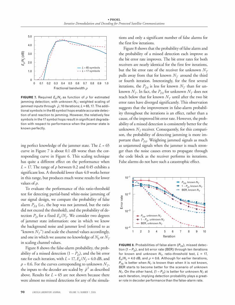
The required Eb /NJ as a function of the jammer frac-tional bandwidth when the channel reliability factor is based on the estimate ρ̂ is illustrated in Figure 7. There is a minimal degradation in performance for L = 65 due to detecting jamming and estimating LJ rather than us-
• PHOELIterative Demodulation and Decoding for Protected Satellite Communications
90 LINCOLN LABORATORY JOURNAL VOLUME 15, NUMBER 1, 2005
ing perfect knowledge of the jammer state. The L = 65 curve in Figure 7 is about 0.1 dB worse than the cor-responding curve in Figure 6. This scaling technique has quite a different effect on the performance when L = 17. The range of ρ between 0.2 and 0.45 exhibits a significant loss. A threshold lower than 4.0 works better in this range, but produces much worse results for lower values of ρ.
To evaluate the performance of this ratio-threshold test for detecting partial-band white-noise jamming of our signal design, we compare the probability of false alarm PFA (i.e., the hop was not jammed, but the ratio did not exceed the threshold), and the probability of de-tection PD for a fixed Eb /NJ. We consider two degrees of jammer state information: one in which we know the background noise and jammer level (referred to as “known NT”) and scale the channel values accordingly, and one in which we assume no knowledge of N0 or NT in scaling channel values.
Figure 8 shows the false-alarm probability, the prob-ability of a missed detection (1 – PD), and the bit error rate for each iteration, with L = 17, Eb /NJ = 4.0 dB, and ρ = 0.6. For the curves corresponding to unknown NT, the inputs to the decoder are scaled by ρ̂2 as described above. Results for L = 65 are not shown because there were almost no missed detections for any of the simula-
tions and only a significant number of false alarms for the first few iterations.
Figure 8 shows that the probability of false alarm and the probability of a missed detection each improve as the bit error rate improves. The bit error rates for both receivers are nearly identical for the first few iterations, but the bit error rate of the receiver for unknown NT pulls away from that for known NT around the third or fourth iteration. Interestingly, for the first several iterations, the PFA is less for known NT than for un-known NT. In fact, the PFA for unknown NT does not reach below that for known NT until after the two bit error rates have diverged significantly. This observation suggests that the improvement in false-alarm probabil-ity throughout the iterations is an effect, rather than a cause, of the improved bit error rate. However, the prob-ability of a missed detection is consistently better for the unknown NT receiver. Consequently, for this compari-son, the probability of detecting jamming is more im-portant than PFA. Weighting jammed signals as much as unjammed signals when the jammer is much stron-ger than the noise causes errors to propagate through the code block as the receiver performs its iterations. False alarms do not have such a catastrophic effect.
FIGURE 7. Required Eb/NJ as function of ρ for estimated jamming detection; with unknown NT; weighted scaling of jammed inputs through ρ̂ ; 10 iterations; L = 65, 17. The addi-tional symbols in the 65 symbol hops enable accurate detec-tion of and reaction to jamming. However, the relatively few symbols in the 17 symbol hops result in significant degrada-tion with respect to performance when the jammer state is known perfectly.
0 0.1 0.3 0.5 1.00.2 0.4 0.6 0.7 0.8 0.9
1.0
0
2.0
3.0
4.0
5.0
E b/N
J (d
B)
L = 65 symbolsL = 17 symbols
Fractional bandwidth ρ
FIGURE 8. Probabilities of false alarm (PFA), missed detec-tion (1 – PD), and bit error rate (BER) through ten iterations for known and unknown NT, ratio-threshold test, L = 17, Eb/NJ = 4.0 dB, and ρ = 0.6. Although for earlier iterations, PFA is better when NT is known than when it is not known, BER starts to become better for the scenario of unknown NT. On the other hand, (1 – PD) is better for unknown NT at each iteration, implying detection probability plays a great-er role in decoder performance than the false-alarm rate.
PFA, unknown NT1 − PD, unknown NTBER, unknown NT
32 4 6 8 1091 5 710–4
10–3
10–2
10–1
Iteration
Erro
r rat
e
PFA, known NT1 − PD, known NTBER, known NT
• PHOELIterative Demodulation and Decoding for Protected Satellite Communications
VOLUME 15, NUMBER 1, 2005 LINCOLN LABORATORY JOURNAL 91
Conclusion
This article discusses a signal design for reliable pro-tected communication in the presence of jamming. In addition, we introduce a ratio-threshold test for PSK for a frequency-hopped communications system suf-fering from partial-band white-noise jamming. With only one reference symbol per dwell, the receiver must use the data-bearing symbols in the hop to correct for the random phase experienced on each hop as well as to detect the presence of jamming. The ratio-threshold test estimates the presence of jamming in a hop. That information is then used to scale the channel values in the dwell interval appropriately for use in iterative APP demodulation and decoding.
The ratio-threshold test detects jamming well, with both the probability of false alarm and the probability of detection improving throughout the iterations. Of the two dwell interval lengths considered, that with more hops per code block performs the best when perfect knowledge of the jammer state is available. However, when the receiver must estimate this side information, both configurations perform similarly, with a modest gain from having more symbols in a hop. Clearly, more symbols per dwell are preferable from the perspective of estimating jamming and exploiting phase coherence.
R E F E R E N C E S 1. C. Berrou and A. Glavieux, “Near Optimum Error Correct-
ing Coding and Decoding: Turbo-Codes,” IEEE Trans. Com-mun. 44 (10), 1996, pp. 1261–1271.
2. K. Chugg, A. Anastasopoulos, and X. Chen, Iterative Detec-tion: Adaptivity, Complexity Reduction, and Applications (Klu-wer, Boston, 2001).
3. K.R. Narayanan and G.L. Stuber, “A Serial Concatenation Approach to Iterative Demodulation and Decoding,” IEEE Trans. Commun. 47 (7), 1999, pp. 956–961.
4. M. Peleg, S. Shamai (Shitz), and S. Galan, “Iterative Decod-ing for Coded Noncoherent MPSK Communications over Phase-Noisy AWGN Channel,” IEE Proc. Commun. 147 (2), 2000, pp. 87–95.
5. G. Colavolpe, G. Ferrari, and R. Raheli, “Noncoherent Itera-tive (Turbo) Decoding,” IEEE Trans. Commun. 48 (9), 2000, pp. 1488–1498.
6. M. Peleg and S. Shamai (Shitz), “Iterative Decoding of Cod-ed and Interleaved Noncoherent Multiple Symbol Detected DPSK,” Electron. Lett. 33 (12), 1997, pp. 1018–1020.
7. P. Hoeher and J. Lodge, “‘Turbo DPSK’: Iterative Differen-
tial PSK Demodulation and Decoding,” IEEE Trans. Com-mun. 47 (6), 1999, pp. 837–843.
8. L. Zhang and A. Burr, “Phase Estimation with the Aid of Soft Output from Turbo Decoding,” Proc. 2001 IEEE Vehicular Technology Conf. 1, Atlantic City, N.J., 7–11 Oct. 2001, pp. 154–158.
9. A. Anastasopoulos and K.M. Chugg, “Adaptive Iterative De-tection for Phase Tracking in Turbo Coded Systems,” IEEE Trans. Commun. 49 (12), pp. 2135–2144.
10. J.H. Kang and W.E. Stark, “Turbo Codes for Coherent FH-SS with Partial Band Interference,” Proc. IEEE 1997 Military Communications Conf. 1, Monterey, Calif., 3–5 Nov. 1997, pp. 5–9.
11. J.H. Kang and W.E. Stark, “Turbo Codes for Noncoherent FH-SS with Partial Band Interference,” IEEE Trans. Com-mun. 46 (11), 1998, pp. 1451–1458.
12. M.A. Jordan, “Turbo Code Performance in Partial-Band Jamming,” Proc. 1998 IEEE Military Communications Conf. 3, Bedford, Mass., 19–21 Oct. 1998, pp. 982–986.
13. M.B. Pursley and J.S. Skinner, “Turbo Product Coding in Frequency-Hop Wireless Communications with Partial-Band Interference,” Proc. 2002 IEEE Military Communica-tions Conf. 2, Anaheim, Calif., 7–10 Oct. 2002, pp. 774–779.
14. A.J. Viterbi, “A Robust Ratio-Threshold Technique to Miti-gate Tone and Partial Band Jamming in Coded MFSK Sys-tems,” Proc. 1982 IEEE Military Communications Conf. 1, pp. 22.4.1–22.4.5.
15. W.G. Phoel, “Side Information for Iterative Demodulation and Decoding of Frequency-Hopped PSK in Partial-Band Jamming,” Proc. 2003 IEEE Military Communications Conf., Boston, 13–16 Oct. 2003.
16. P. Sehier, P. Brelivet, and I. Aubry, “A New Jammer Estima-tion Method Adapted to FH-PSK Waveforms,” Proc. 1994 IEEE Military Communications Conf. 3, 2–5 Oct. 1994, Long Branch, N.J., pp. 1027–1031.
17. H. El Gamal and E. Geraniotis, “Iterative Channel Estima-tion and Decoding for Convolutionally Coded Anti-Jam FH Signals,” IEEE Trans. Commun. 50 (2), pp. 321–331.
18. W.G. Phoel, “Serially Concatenated Convolutional Coding for Frequency-Hopped PSK in Partial-Band Jamming,” Proc. 2002 IEEE Military Communications Conf. 2, Anaheim, Ca-lif., 7–10 Oct. 2002, pp. 763–767.
19. J. Hagenauer, E. Offer, and L. Papke, “Iterative Decoding of Binary Block and Convolutional Codes,” IEEE Trans. Inf. Theory 42 (2), 1996, pp. 429–445.
20. P. Robertson, E. Villebrun, and P. Hoeher, “A Comparison of Optimal and Sub-Optimal MAP Decoding Algorithms Operating in the Log Domain,” Proc. 1995 IEEE Interna-tional Conf. on Communications (ICC ’95), Seattle, 18–22 June 1995, pp. 1009–1013.
21. S. Benedetto, D. Divsalar, G. Montorsi, and F. Pollara, “Serial Concatenation of Interleaved Codes: Performance Analysis, Design, and Iterative Decoding,” IEEE Trans. Inf. Theory 44 (3), 1998, pp. 909–926.
• PHOELIterative Demodulation and Decoding for Protected Satellite Communications
92 LINCOLN LABORATORY JOURNAL VOLUME 15, NUMBER 1, 2005
A PPE N DI X : T U R B O DE C ODI N G A N D T H E A PP A L G OR I T H M
The a posteriori probability (APP) decoding algorithm is based on the symbol-by-symbol maximum a posterio-ri (MAP) algorithm [1]. The MAP decoder makes each bit decision b̂k to maximize the probability that that bit was sent, given the entire received sequence
ˆ arg max Pr( | ) ,{ , }
b bkb
kk
=∈ + −1 1
r
where bk is the kth bit of the block of N information bits encoded in the transmitted code word, and r represents the received sequence corresponding to the code word. To ease notation later in this appendix, we assume that the binary digits 0 and 1 are already mapped to +1 and –1. Figure A shows a simplified block diagram relating bits to code words. For each bit, we can calculate the log-APP ratio
λkk
k
bb
= = +=
log
Pr( | )Pr( – | )
,11
rr
and decide that +1 was sent if λk > 0, and decide that –1 was sent otherwise. The turbo decoder differs from the MAP decoder in the following way. Rather than mak-ing hard decisions on the bits and stopping, the turbo-decoding algorithm keeps the soft information in the
log-APP ratio and passes it between constituent decod-ers. The soft output of one decoder is called extrinsic information and is used as a priori information in the other decoder.
The remainder of this appendix describes how to compute λk based on the code word estimate and a priori information. A detailed description of the APP al-gorithm and turbo decoding for PCCCs can be found elsewhere [2].
We calculate the APP by applying Bayes’ rule,
Pr( | )
Pr( , )Pr( )
,bb
kkr
rr
=
and note that Pr(r) is the same in the numerator and denominator of the APP ratio and therefore will cancel when computing λk. We then take advantage of the fact that the convolutional codes we are considering can be represented as finite state machines. The joint probabil-ity of bk and r, or Pr( , )bk r , can be computed by sum-ming over the joint probabilities of r with all informa-tion sequences with the desired value for bk. Because of the finite state machine representation, this expression can be written as the sum over all state transitions cor-responding to the desired value of bk
Pr( , ) Pr( , )
Pr( , , ) ,
|
( , )|
b
s s s s
kb
k ks s b
k
k
r b r
r
b
=
= = ′ =
∑∑ −′
1
where b is the sequence of N information bits, b|bk denotes all information sequences with the desired bit value in the kth position, and sk is the state of the con-volutional code at index k.
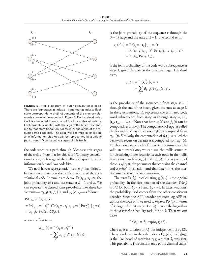
The convolutional code can also be described on a trellis. Figure B shows the trellis for the outer convo-lutional code considered in this article. Each branch is labeled with the sign of the information bit that leads to that state transition, followed by the signs of the result-ing code bits. For the discussion here, we can think of
FIGURE A. A simplified block diagram showing the rela-tionship between the input bits bk, the code word subse-quences vk (where we assume that n code bits are gener-ated for each input bit, so that vk is an n-element column vector), and the noisy estimate of the code word subse-quence rk. The vector wk is an n-element column vector of white Gaussian noise samples.
bk vk
wk
rkConvolutionalencoder
• PHOELIterative Demodulation and Decoding for Protected Satellite Communications
VOLUME 15, NUMBER 1, 2005 LINCOLN LABORATORY JOURNAL 93
the code word as a path through N consecutive stages of the trellis. Note that for this rate-1/2 binary convolu-tional code, each stage of the trellis corresponds to one information bit and two code bits.
We now have a representation of the probabilities to be computed, based on the trellis structure of the con-volutional code. It remains to derive Pr( , , )s sk k−1 r , the joint probability of r and the states at k – 1 and k. We can separate the desired joint probability into three ba-sic terms—αk s−1( ), βk s( ), and γ k s s( , )′ —as follows:
Pr( , , )
Pr( , )Pr(
s s s s
s s s s
k k
kk
k
−
−−
= ′ =
= = ′ =1
1 11
r
r ,, | )Pr( | )
( ) ( ,
r rk k kN
k
k k
s s s s
s s s− +
−
= ′ == ′ ′
1 1
1α γ )) ( ),βk s
where the first term,
α
α γ
k kk
k ks
s s s
s s s
−−
− −′
= =
= ′ ′1 1
1
2 1
( ) Pr( , )
( ) ( , )
r
∑∑ ,
is the joint probability of the sequence r through the (k – 1) stage and the state at k – 1. The second term,
γ k k k k
k k k k k
k k k
s s s s s s
s s s s s s s s
b b
( , ) Pr( , | )
Pr( | )Pr( | , )
Pr( )Pr( | ) ,
′ = = = ′= = = ′ = = ′=
−
− −
r
r
r
1
1 1
is the joint probability of the code word subsequence at stage k, given the state at the previous stage. The third term,
β
β γ
k kN
k
k ks
s s s
s s s
( ) Pr( | )
( ) ( , ) ,
= =
= ′+
+ +∑r 1
1 1
is the probability of the sequence r from stage k + 1 through the end of the block, given the state at stage k. In these expressions, rm
n represents the estimated code word subsequence from stage m through stage n, i.e., {rm, rm+1, …, rn}. Note that both αk(s) and βk(s) can be computed recursively. The computation of αk(s) is called the forward recursion because αk(s) is computed from αk–1(s). Similarly, the computation of βk(s) is called the backward recursion because it is computed from βk+1(s). Furthermore, since each of these terms sums over the valid state transitions, we can use the trellis structure for visualizing these recursions; each node in the trellis is associated with an αk(s) and a βk(s). The key to all of these is γk(s', s), the parameter that contains the channel and a priori information and that determines the met-rics associated with state transitions.
The term Pr(bk) in calculating γk(s', s) is the a priori probability. In the first iteration of the decoder, Pr(bk) is 1/2 for both bk = +1 and bk = –1. In later iterations, the probability used comes from the other constituent decoder. Since the APP decoder produces log-APP ra-tios for the code bits, we need to express Pr(bk) in terms of its log-probability ratio. Let ′λk denote the logarithm of the a priori probability ratio for bit k. Then we can write
Pr( ) exp( / ) ,b B bk k k k= ′λ 2
where Bk is a function of ′λk but independent of bk [2]. The second term in the calculation of γk(s', s), Pr(rk|bk), is the likelihood of receiving rk given that bk was sent. This probability is a function only of the channel values
FIGURE B. Trellis diagram of outer convolutional code. There are four states at index k – 1 and four at index k. Each state corresponds to distinct contents of the memory ele-ments shown in the encoder in Figure 3. Each state at index k – 1 is connected to only two of the four states of index k. Each branch is labeled with the sign of the bit correspond-ing to that state transition, followed by the signs of the re-sulting two code bits. The code word formed by encoding an N information bit block can be represented by a unique path through N consecutive stages of this trellis.
+/++
sk−1 sk
−/−−
+/−+
−/+−
+/−−
−/++
+/+−
−/−+
• PHOELIterative Demodulation and Decoding for Protected Satellite Communications
94 LINCOLN LABORATORY JOURNAL VOLUME 15, NUMBER 1, 2005
for stage k,
Pr( | ) exp
exp ,
rr v
r v
k kk k
k kT
k
b
n
C
=
− −
=
1
2 2
1
2
2
2
2
πσ σ
σ
where we assume that rk = vk + wk, as illustrated in Fig-ure A, and wk is a length-n vector of Gaussian random variables with variance σ 2 per element. It follows that we can write
γ λ
σk k k k k k
Tks s B C b( , ) exp .′ = +
′12
12
r v
We now have expressions to calculate the log-APP ratio from the code word estimate r and the log a priori probability ratio ′λk , but performing these operations in the probability domain can be numerically unstable. It also requires many multiplications which, in general, are more complicated to implement than additions. Consequently, we consider how to implement the APP algorithm in the log domain. To do so, we first define the function
max*( , ) ln( )
max( , ) ln( ),
a b e e
a b e
a b
a b
≡ +
= + − −1
which can be implemented by using a look-up table for the log term, and then only for values of |a – b| small enough to make a significant difference. A variation on this decoder neglects the table look-up and computes the maximum only in each case where the max* operation occurs. Such a decoder is often referred to as the max-log-APP or max-log-MAP decoder. The max-log-APP decoder tends to perform within a fraction of a decibel of the log-APP decoder but is simpler to implement.
We can now update each of αk(s), βk(s), and γk(s', s) terms as follows:
ln[ ( )] max* ln[ ( )] ln[ ( , )]α α γk
sk ks s s s= ′ + ′{ }
′−1 ,,
ln[ ( )] max* ln[ ( )] ln[ ( , )]β β γk
sk ks s s s′ = + ′{ + +1 1 }},
and
ln[ ( , )] ,γ λ
σk k k k
Tks s b′ ≈ +
′12
22
r v
where the term due to Bk and Ck is omitted because it will cancel in later steps. Consequently, the log-APP ra-tio is given by
λks s b
k kk
s s s s= = ′ ={ }′ =+ −max* ln[Pr( | , )]
( , )| 11 r
−− = ′ ={ }=
′ =− −max* ln[Pr( | , )]( , )|s s b
k kk
s s s s1
1 r
mmax* ln[ ( )] ln[ ( , )]( , )|′ =+ − ′ + ′ +s s b
k kk
s s s1
1α γ lln[ ( )]
max* ln[ ( )] l( , )|
β
α
k
s s bk
s
sk
{ }− ′ +
′ =− −1
1 nn[ ( , )] ln[ ( )] .γ βk ks s s′ +{ }
In general, the values for αk(s) are computed by starting with k = 1 up through k = N, and the βk(s) are com-puted by beginning with k = N and working backward to k = 1.
The extrinsic information used as a priori information in another constituent decoder is formed differently, de-pending on the configuration of the concatenated code. For example, with a PCCC using systematic constitu-ent codes (i.e., the information bits are contained unal-tered within the code word), the extrinsic information passed from one decoder to another is a log-probability ratio of the information bits. However, for the iterative algorithm to remain stable, we need to be careful not to inadvertently reuse information in the same decoder. Specifically, for a particular constituent decoder, inputs directly related to the information bit probabilities are the channel values for the systematic bits and the a priori information from the other decoder. Because the systematic channel values will also be input to the other constituent decoder, we need to remove that informa-tion from the extrinsic information passed between de-coders so that it is not counted twice. In addition, since the a priori information in one decoder came from the other decoder, that information too should be removed from the log-APP ratio before it is passed back as extrin-sic information. Therefore, for the typical PCCC, the value output as extrinsic information on bit k is given by λ ν λk k
sk− − ′ , where νk
s denotes the channel value corresponding to the systematic bit k.
For the SCCC configuration considered in this arti-cle, the situation is somewhat different. First, neither of
• PHOELIterative Demodulation and Decoding for Protected Satellite Communications
VOLUME 15, NUMBER 1, 2005 LINCOLN LABORATORY JOURNAL 95
the codes used is systematic. Second, the actual chan-nel values input to the inner decoder are not directly in-put to the outer constituent decoder. Let’s consider the inner decoder first. The inputs to this decoder are the channel values and the a priori information from the outer decoder. In this case, what are considered the “in-formation” bits of the inner code are actually the code bits of the outer code. The inner decoder implements the APP algorithm and computes the log-probability ra-tio λk for the outer code bits. As discussed above, before this information can be passed to the outer decoder, the a priori information needs to be removed. Therefore, the inner decoder passes to the outer decoder λ λk k− ′ , which the outer decoder interprets as the channel val-ues or, equivalently, the code bit estimates. The outer decoder then performs the APP algorithm on these re-ceived values. However, with this serial concatenation, the log-APP ratio computed is used only for the hard decisions at the end of the iterations. It is extrinsic infor-mation on the code bits that needs to be computed and passed to the inner decoder. This is done in the same way as for the information bits, except that the max* operation is performed over all state transitions with the same value of the particular code bit being considered.
R E F E R E N C E S 1. L.R. Bahl, J. Cocke, F. Jelinek, and J. Raviv, “Optimal De-
coding of Linear Codes for Minimizing Symbol Error Rate,” IEEE Trans. Inf. Theory 20, Mar. 1974, pp. 284–287.
2. W. Ryan, “Concatenated Convolutional Codes and Iterative Decoding,” in Wiley Encyclopedia of Telecommunications, Vol. 1, J.G. Proakis, ed. (Wiley, New York, 2003), pp. 556–570.
• PHOELIterative Demodulation and Decoding for Protected Satellite Communications
96 LINCOLN LABORATORY JOURNAL VOLUME 15, NUMBER 1, 2005
. is a staff member in the Ad-vanced Satcom Systems and Operations group. His cur-rent research interests are in the areas of communications and information theory with emphasis on modulation and coding. At Lincoln Labora-tory he has worked primarily on the design of the protected radio frequency waveform for the Transformational Satel-lite Communications System (TSAT), as well as modula-tion and error-control coding for payload and terminal emulators for the Advanced EHF system. Prior to joining the Laboratory, he contributed to third-generation terres-trial cellular communications research at Motorola Cellular Infrastructure Group, in Arlington Heights, Illinois, and also worked on signal processing for radar applica-tions at Calspan Corporation, in Buffalo, New York. He has B.S. and M.Eng. degrees in electrical engineering from Cornell University, and a Ph.D. degree in electrical and computer engineering from Northwestern University.