55
ITEST TEACHER WORKSHOP MATE Center ITEST Grant Pacific Northwest ROV Regional
| Date post: | 24-Dec-2015 |
| Category: |
Documents |
| Upload: | everett-stewart-flynn |
| View: | 232 times |
| Download: | 2 times |
ITEST TEACHER WORKSHOPMATE Center ITEST Grant
Pacific Northwest ROV Regional

Introductions• Rick Rupan – [email protected]
• Univ. of Washington Oceanography Dept.• ARGO Float Fabrication
• Wes Thompson - [email protected]• Univ. of Washington Applied Physics Lab• Analytical Chemistry
• Fritz Stahr – [email protected]• Univ. of Washington Oceanography Dept.• Seaglider Fabrication Center
• Jill Zande – [email protected]• Marine Advanced Technology Education (MATE) Center• Associate Director & Competition Coordinator• ITEST Project PI

Innovative Technology Experience for Students and Teachers (ITEST)• The ITEST program responds to current concerns and projections
about the growing demand for science, technology, engineering, and mathematics (STEM) professionals in the U.S. and seeks solutions to help ensure the breadth and depth of the STEM workforce.
• MATE ROV Competitions: Providing Pathways to the Ocean STEM Workforce• $1.2Million, 3-year project funded through ITEST/DRL/NSF• Overarching goal: Use the MATE ROV competition as an engaging platform to
prepare middle and high school students for careers in the ocean STEM workforce.• Eight regionals last year, 12 regionals this year• PNW only regional to support ITEST for all three years

ITEST Objectives1. Build the support infrastructure for an entry-level ROV competition
class by a) providing professional development and student support workshops in afterschool and informal settings; and b) developing, adapting, and enhancing ROV focused STEM curriculum materials.
2. Increase ocean STEM career awareness and present trajectories to those careers for middle and high school audiences. (Exploring Ocean Careers Course & OceanCareers.com)
3. Build a cyber learning center to a) foster collaboration and increase communication among students, educators, parents, and working professionals; and b) improve access to STEM instructional resources (MATErover.org)
4. Evaluate and track project participants to determine the impact on a) students’ STEM knowledge, skill development, and inclination to pursue STEM education and careers; and b) teachers’ confidence in facilitating STEM learning experiences and delivering career information.

ITEST Support for Teachers and Students
• Professional development for teachers• Workshops like this one• Teachers leave the workshop with an ROV and sample curricula
• Resources for an extended learning course/club at your schools• Course outline and curriculum materials• Tools, materials, and supplies
• Materials for up to 3 ROVs
• Mentors (professional engineers & technicians, college students and faculty)• Rick, Wes and Fritz as well as our friends at Linn Benton CC and OSU
• Information about education and job opportunities• Oceancarreers.com• MATErover.org

MATE Center• What is the MATE Center?
• MATE Center is national in scope, but works through regional partnerships. Partners help to create new curricula, collect information from employers, and share 'best practices' related to Marine Technology Education.
• What does the MATE Center do?• Workforce assessments• Curriculum development• Summer Institutes for teachers• Technical internships for students
• MATE ROV Competitions• Includes one international competition and 21 regional contests held across the US,
and in Canada, China, Japan and Scotland• PNW Regional
• Getting larger every year, this year expecting 45 teams
• Oregon Scout ITEST Competition• Offering a chance for you to test the skills you learn today by bringing a Scout team to
competition

Comparison of Salaries

SO WHAT EXACTLY ARE THESE ROV THINGS?

Remotely Operated Vehicles• These robots have a long history of salvage, research,
exploration• They are connected to the pilot on the surface with a
tether• All power and communication happen through this cable
• First designs came from the Navy for salvage operations
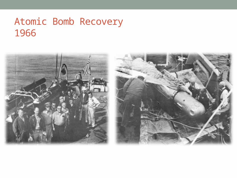
Atomic Bomb Recovery1966

Navy Advancements
Mine Neutralization Advanced Tethered Vehicle

Classes of ROVs
• How big do these get?
Kaiko, First ROV to Challenger Deep10,916 meters (6.8 miles)
How Big Do These Things Get?Classes of ROVs

Observation Class ROVs
• Small robots (<200 lbs), “low” cost• Primarily used for inspection and
observation• Typically all electric with shallow
operating depth (~300 m)

The Flying Eyeballs
• Thought of as Diver Assistants
• Slip into tight or dangerous spaces
• Can help place or lift heavy items

Work Class ROVs
• Drilling support, construction, inspections, scientific research
• Increased payload and depth capability
• Hydraulic manipulators
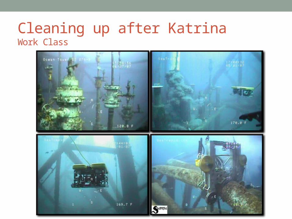
Cleaning up after KatrinaWork Class
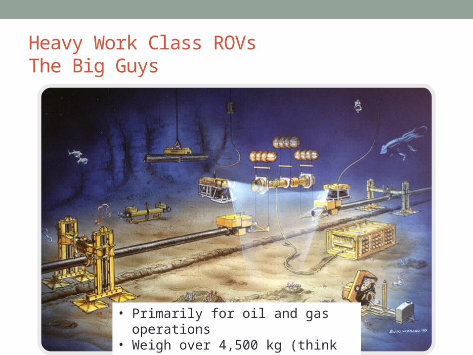
Heavy Work Class ROVsThe Big Guys
• Primarily for oil and gas operations• Weigh over 4,500 kg (think minivan)• Work at depths over 3,000 m

Oil Spill Fixers

Bottom Crawlers

Competition Class ROVs
Basic ROV Physics• Newton’s Laws
• Basic Definitions• What is a force, f=ma
• 4 forces for ROVs• Weight• Buoyancy - Archimedes• Thrust• Drag
• Centers of …• Gravity• Buoyancy• Thrust
Newton’s Laws• Newton’s First Law
• An object in motion will remain in motion unless acted upon by another force
• Newton’s Second Law• The relationship between an object’s mass and its acceleration is
its force. F=m·a
• Newton’s Third Law• For every action there is an equal and opposite reaction

So what forces act on our ROVs?• Weight
• A force on an object defined by the product of the object’s weight and the acceleration due to gravity
• Buoyancy• The magnitude of the buoyant force acting on an object is equal to
the weight of the fluid displaced by the object
• Drag• A force that resists the relative motion between and object and the
fluid surrounding it
• Thrust• An energy requiring, propulsive force used to control vehicle
motion

Weight• The mass of an object is pulled towards the center
another object at a given acceleration. This is gravity, and on Earth is equal to 9.8 m/s2
• Gravity is an acceleration and can be used in Newton’s Second Law, F=m·a
• Weight is the force exerted on a mass by gravity. Inserting this to Newton’s Second Law gives F(weight)=m·a(gravity) or W=m·g

Buoyancy
Objects that float upward are positively buoyantDobject < Dfluid
Objects that neither rise nor sink are neutrally buoyantDobject = Dfluid
Objects that sink are negatively buoyantDobject > Dfluid
An object in a fluid will displace an amount of fluid equal to its volume. The volume is used to determine the density of the object (D = mass/vol). To determine buoyancy, the density of the fluid and the density of the object can be compared.
Most ROVs are close to neutrally buoyant. This allows the operator to control the vehicle’s position with a motor, rather than try to change its buoyancy.

Drag• Drag resists the movement of an
object through a fluid• The shape of your vehicle will
determine its drag• Drag increases dramatically as
speed increases• Reduce the drag to more efficiently
propel your vehicle through the water

Thrust
• Propellers accelerate water away from their faces (Newton’s Second)
• Water is forced away from the propeller which in turn pushes the vehicle in the opposite direction (Newton’s Third)

STABILITY AND BALLASTING

Basic Physics
• Center of Gravity• Balance your ROV on your fingers• Make sure weight is evenly distributed
• Center of Buoyancy• Floatation above weights!!• The further apart your weights and floats, the harder it is to flip
your ROV
• Center of Thrust• Keep this close to your center of gravity
• That doesn’t necessarily mean your thrusters have to be dead center in your ROV
• They can be spread out (allows for faster turning) but align your centers

Center of Gravity• The imaginary center of the weight of your vehicle• If symmetrically weighted, located at geometric center

Center of Gravity• CG will change as weight is added to your vehicle• If you are asymmetric with your weight distribution your
CG will change location

Center of Gravity• If not properly ballasted, your vehicle will tilt in water to
align the CG with the heaviest part of your vehicle

Center of Buoyancy• CB is determined by the floatation of your vehicle• CB will always be in the same vertical plane as your CG
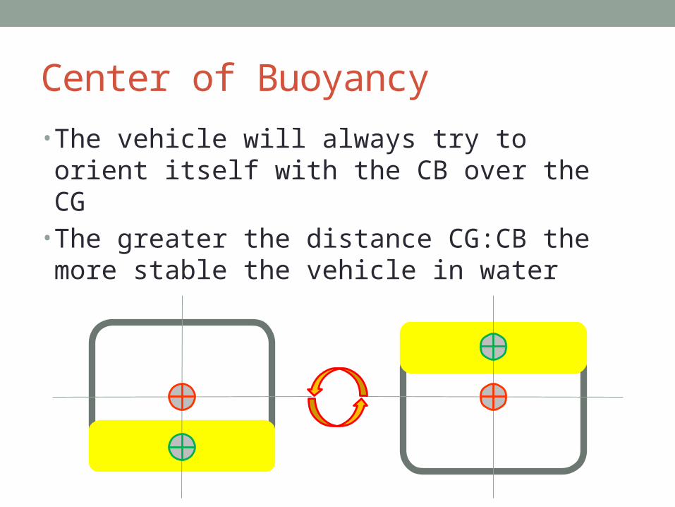
Center of Buoyancy
• The vehicle will always try to orient itself with the CB over the CG
• The greater the distance CG:CB the more stable the vehicle in water
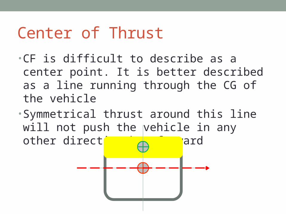
Center of Thrust
• CF is difficult to describe as a center point. It is better described as a line running through the CG of the vehicle
• Symmetrical thrust around this line will not push the vehicle in any other direction but forward
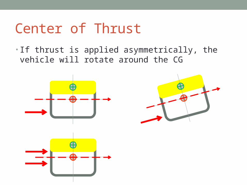
Center of Thrust• If thrust is applied asymmetrically, the vehicle will rotate
around the CG
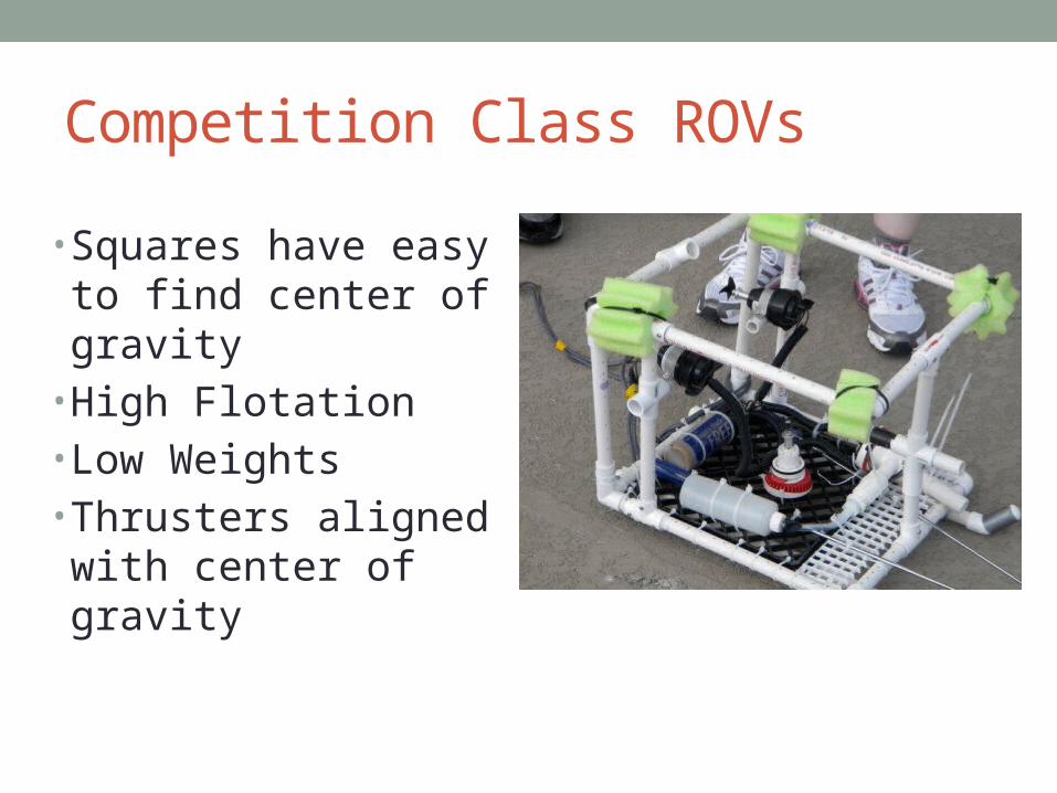
Competition Class ROVs
• Squares have easy to find center of gravity
• High Flotation• Low Weights• Thrusters aligned with center of gravity

Electricity• Flow of electrons
• Voltage/Amperage• Series and Parallel
• Battery• Fuses• Switches
• Spst, dpdt
• Motors• Volts and amps

Electricity and Circuits
• Charge• Electrical property associated with protons (+) and
electrons (-)• Opposite charges attract each other (like magnets)• Electricity is the flow of charge as the two opposite
charges attract each other
• Batteries separate charges through a chemical imbalance• This imbalance generates an electromotive force (voltage)
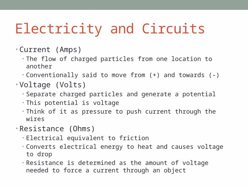
Electricity and Circuits• Current (Amps)
• The flow of charged particles from one location to another• Conventionally said to move from (+) and towards (-)
• Voltage (Volts)• Separate charged particles and generate a potential• This potential is voltage• Think of it as pressure to push current through the wires
• Resistance (Ohms)• Electrical equivalent to friction• Converts electrical energy to heat and causes voltage to drop• Resistance is determined as the amount of voltage needed to force
a current through an object
Electricity and Circuits
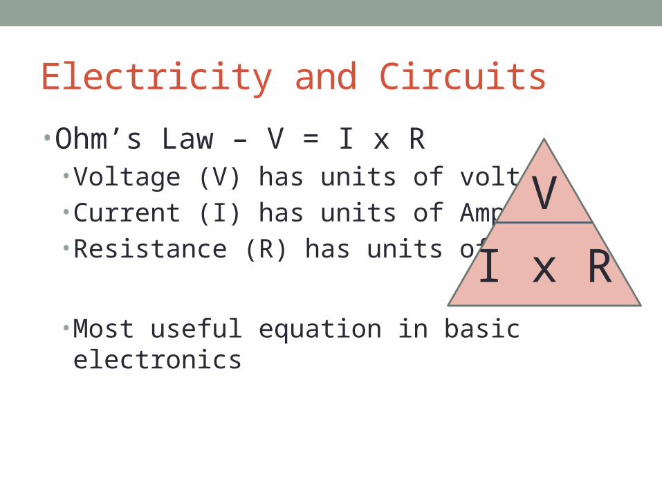
• Ohm’s Law – V = I x R• Voltage (V) has units of volts• Current (I) has units of Amps• Resistance (R) has units of Ohms
• Most useful equation in basic electronics
V
I x R

Electricity and Circuits
Current flows through loops called circuits which have three fundamental parts
• Voltage source: Battery, wall outlet, etc.• Load: something that does work with electricity, a light
source, motor, heater, etc.• Switch: When closed, completes the circuit and allows
current to flow. When open, breaks the loop and current stops.
+
-
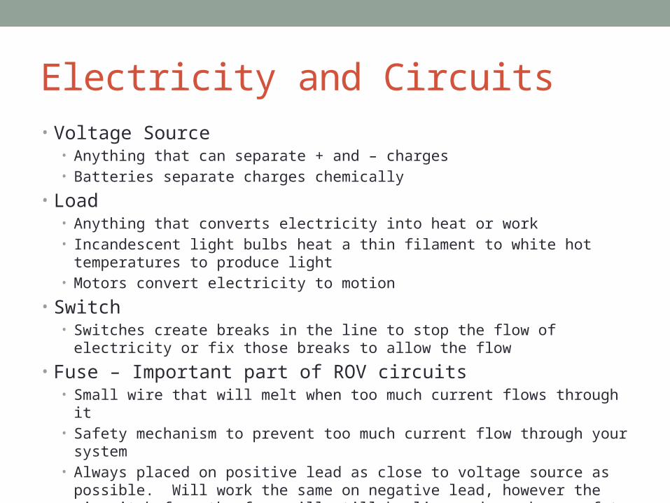
Electricity and Circuits• Voltage Source
• Anything that can separate + and – charges• Batteries separate charges chemically
• Load• Anything that converts electricity into heat or work• Incandescent light bulbs heat a thin filament to white hot temperatures to produce
light• Motors convert electricity to motion
• Switch• Switches create breaks in the line to stop the flow of electricity or fix those breaks to
allow the flow
• Fuse – Important part of ROV circuits• Small wire that will melt when too much current flows through it• Safety mechanism to prevent too much current flow through your system• Always placed on positive lead as close to voltage source as possible. Will work the
same on negative lead, however the circuit before the fuse will still be live and can be a safety hazard.

Switches• Switches create breaks in the circuit loop stopping the
flow of charge• The most simple switch is called ‘single pole, single throw’
• Either on or off, like a light switch
• A little more complicated is the ‘single pole, double throw’• Like an ‘either / or’ switch, send current in either this direction or in
this other direction

Switches - DPDT• The switches we use in our control box are called ‘Double
Pole, Double Throw’• Exactly like two SPDT switches put together• This allows control of four lines with one switch
• Two positive and two negative lines
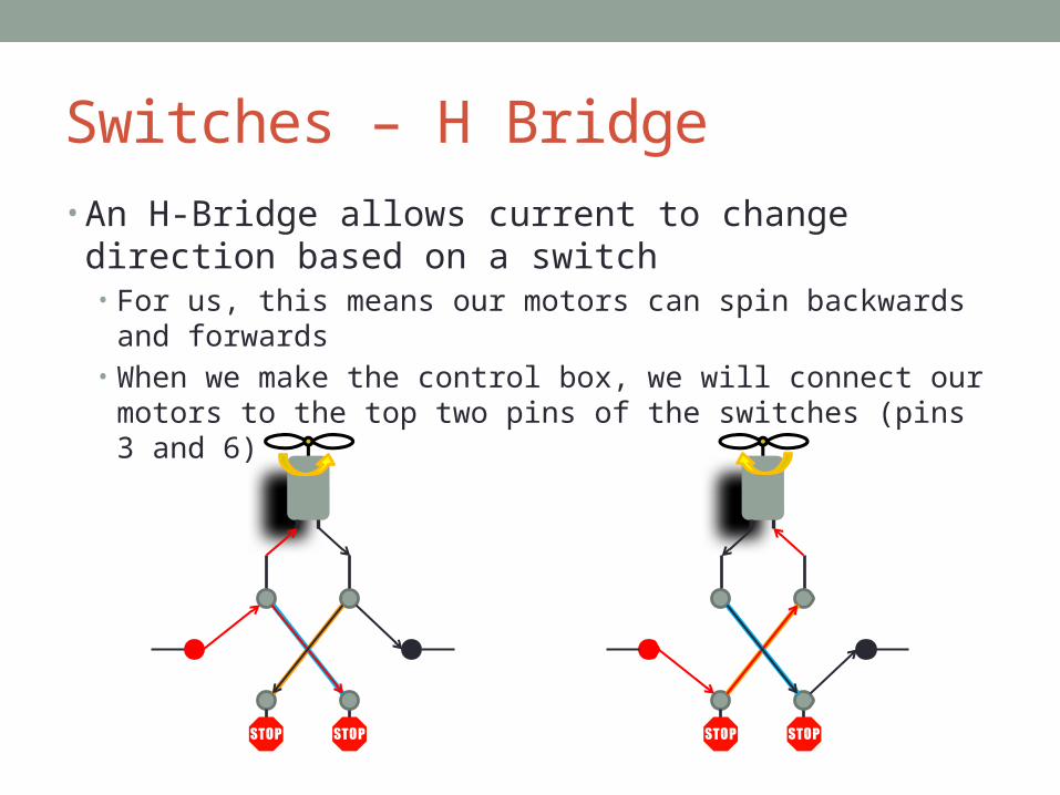
Switches – H Bridge• An H-Bridge allows current to change direction based on
a switch• For us, this means our motors can spin backwards and forwards• When we make the control box, we will connect our motors to the
top two pins of the switches (pins 3 and 6)

Electricity and Circuits
Series Circuit
• Two or more components connected end to end so current flowing through one component must then flow through the next
• Current flowing through will always be equal but voltages may not be (depends on the resistance of the component, Ohm’s Law)
• The voltage from one end to the next will be equal to the sum of the voltages across the components
+
-

Electricity and Circuits
Parallel Circuit
• In this arrangement, components are exposed to the exact same voltage, however current will be divided among the components.• Current does not need to (and probably will not)
be equal across each component (again resistance and Ohm’s Law)
+ -
Intro to Soldering• Wet sponge!
• The hot iron easily oxidizes and a wet sponge will clean this off. A dry sponge can damage the tip.
• Clean iron• Every time you pass over the sponge, clean your iron. When you first pick it up and when
you last place it back, clean your iron!
• Heat Shrink First• Heat shrink covers your solder connections so it does not short circuit and will waterproof
connections as well.
• Good mechanical connection• Solder is not a strong metal. A good physical connection by twisting the wires together is
necessary to ensure they don’t break apart.
• Tin your tip• Quickly touch solder to the tip of the iron to leave a small bead of molten solder on the
tip. This facilitates the flow of heat into your joint. Note: the side of the tip of the soldering iron is hotter than the point
• Touch the molten bead to your wire joint• Heat will flow into the wire, touch the solder to the wire and watch it flow
• Know where cord is? Don’t burn it, others or you
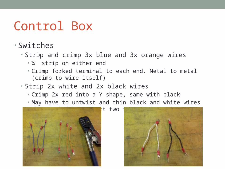
Control Box• Switches
• Strip and crimp 3x blue and 3x orange wires• ¼” strip on either end• Crimp forked terminal to each end. Metal to metal (crimp to wire itself)
• Strip 2x white and 2x black wires• Crimp 2x red into a Y shape, same with black• May have to untwist and thin black and white wires down by half to
insert two into fork terminal

Control Box• Polarity Cross
• Connect orange wires to pins 1 and 6• Connect blue wires to pins 3 and 4
• Install switches into box lid• Look at pin number, install with
pin 1 bottom left. This is important!
• Install Y wires• Center of Y on switch 1• White Y connects pin 2 all switches• Black Y connects pin 5 all switches
321
654
1
2
3

Control Box Contd.• Strip and crimp Tether Cable, both sides
• Strip grey jacket 6” on both sides w/o cutting cables below• Control Box Side, strip all 6 wires ¼” and crimp terminals• Motor Side, strip all 6 wires 1”, do not crimp. Will solder later.
• Insert control box end of tether through control box• Tie figure 8 for strain relief• Connect Important: Connect color wire to the pin and switch
specified!• Black to pin 3 switch 1• White to pin 6 switch1• Blue to pin 3 switch 2• Red to pin 6 switch 2• Brown to pin 3 switch 3• Green to pin 6 switch 3
• Strip and crimp one end of power cable• Install crimped end of power cable to control box, tie figure 8
for strain relief• Smooth wire (positive) to white (pin 2 switch 1)• Connect ribbed wire (negative) to black (pin 5 switch 1)
1
2
3

Thruster Soldering• Install props onto motor mount
• Put small amount of LockTite on threads of screw• Install motor mount onto motor shaft
• Align set screw with flat part of motor shaft• Set screw should screw flat into mount body
• Strip Motor leads 1”
• Prepare to solder• Get irons hot, ~ 5 min• Wet Sponge, clean iron tip!• 2” heat shrink, be sure to place on wires before soldering • Twist wires together, good mechanical connection
• Important: Connect colored wires to their respective motor wire!
• Black wire to motor brown left handed prop positive• White wire to motor black left handed prop negative
• Left handed prop marked with ‘L’
• Red wire to motor brown right handed prop positive• Blue to motor black right handed prop negative
• Brown wire to motor brown right handed prop positive• Green to motor black right handed prop negatives
• Cover solder joints with heat shrink and shrink
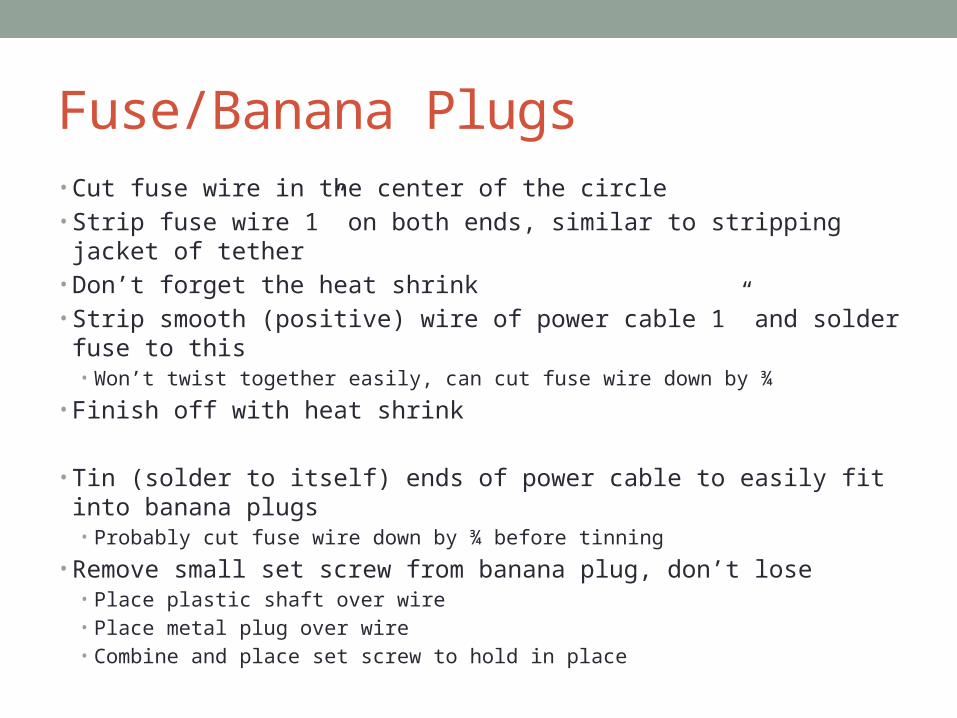
Fuse/Banana Plugs• Cut fuse wire in the center of the circle• Strip fuse wire 1” on both ends, similar to stripping jacket of tether• Don’t forget the heat shrink• Strip smooth (positive) wire of power cable 1” and solder fuse to this
• Won’t twist together easily, can cut fuse wire down by ¾
• Finish off with heat shrink
• Tin (solder to itself) ends of power cable to easily fit into banana plugs• Probably cut fuse wire down by ¾ before tinning
• Remove small set screw from banana plug, don’t lose• Place plastic shaft over wire• Place metal plug over wire• Combine and place set screw to hold in place

Final Product


