VANDERBILT STUDENT VOLUNTEERS FOR SCIENCE http://studentorgs.vanderbilt.edu/vsvs Electricity – Resistors and Capacitors (Adapted from Student Guide for Electric Snap Circuits by Elenco Electronic Inc.) Acknowledgement: We want to thank NASA and the Tennessee Space Consortium for funds to purchase the electric circuit kits. GOAL: To learn about the function of resistors and capacitors in electric circuits. LESSON OUTLINE I. Introduction Explain what resistors and capacitors are. All the activities today will be done at stations. II. Testing Resistors A. Individual Resistors Students observe the relative brightness of the LED bulb and the current flowing through the circuit as R1, R2, and R3 are placed in the circuit (Diagram 1 on the Instruction Sheet). B. Resistors in Series and Parallel 1. Series Students observe how the relative brightness of the LED bulb and current change by placing R2 in the circuit first and then adding R3 in series according to Diagram 2 in the Instruction Sheet. 2. Parallel Students observe how the relative brightness of the LED bulb and current change by placing R3 in the circuit first and then adding R2 in parallel according to Diagram 3 in the Instruction Sheet. III.Testing Capacitors C. Individual Capacitors Students observe both the brightness and the length of time the LED is lit for C4, C3, C5, and C2 capacitors. D. Capacitors in Series and Parallel 1
Transcript
VANDERBILT STUDENT VOLUNTEERS FOR SCIENCEhttp://studentorgs.vanderbilt.edu/vsvs
Electricity – Resistors and Capacitors(Adapted from Student Guide for Electric Snap Circuits by Elenco Electronic Inc.)
Acknowledgement: We want to thank NASA and the Tennessee Space Consortium for funds to purchase the electric circuit kits.
GOAL: To learn about the function of resistors and capacitors in electric circuits.
LESSON OUTLINEI. Introduction Explain what resistors and capacitors are. All the activities today will be done at stations. II. Testing Resistors
A. Individual ResistorsStudents observe the relative brightness of the LED bulb and the current flowing through the circuit as R1, R2, and R3 are placed in the circuit (Diagram 1 on the Instruction Sheet).B. Resistors in Series and Parallel
1. SeriesStudents observe how the relative brightness of the LED bulb and current change by placing R2 in the circuit first and then adding R3 in series according to Diagram 2 in the Instruction Sheet.2. ParallelStudents observe how the relative brightness of the LED bulb and current change by placing R3 in the circuit first and then adding R2 in parallel according to Diagram 3 in the Instruction Sheet.
III. Testing CapacitorsC. Individual CapacitorsStudents observe both the brightness and the length of time the LED is lit for C4, C3, C5, and C2 capacitors.D. Capacitors in Series and Parallel
1. SeriesStudents observe both the brightness and the length of time the LED is lit for C3 and C5 in series.2. ParallelStudents observe both the brightness and the length of time the LED is lit for C3 and C5 in parallel.
BEFORE RETURNING THE CIRCUITS TO THE BOX, MAKE SURE ALL THE CIRCUIT COMPONENTS ARE PLACED AS IN THE PICTURE.
MATERIALS5 Resistor Circuits (used for measuring effect of different individual resistors and effect of resistors in series and parallel circuits)5 Capacitor Circuits (used for measuring effect of individual capacitors)Instruction SheetsWork Sheets
I. Introduction – Background information is presented here. Discuss as appropriate for the level of your students.
ResistorsA resistor, like batteries and lights, can also be present in an electrical circuit. A resistor limits the flow of electricity in the circuit. Like rocks in a pipe that slow the flow of water, a resistor will limit the flow of electricity. A variable resistor is made of a piece of metal that can change in length. As the length of the resistor changes, so does the resistance in the same direction.
Units: The unit for resistors is the ohm, Ω. Resistance is defined as the ratio of the voltage to the current, R = V/A, where V is volts and A is current measured in amperes. One ohm is the resistance, R, that permits a current of 1 A to flow through a circuit with 1 V. The connecting wires in electric circuits have very low resistance; the copper wire used to wire houses has about 0.004 ohms per meter.
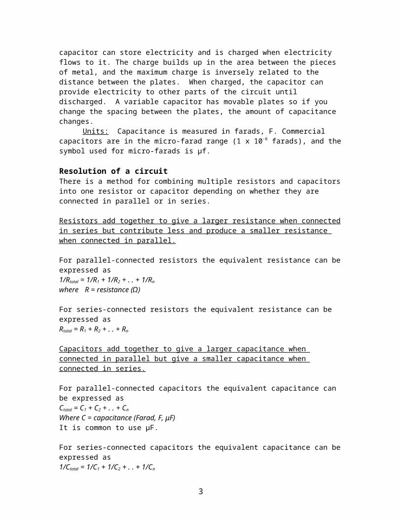
CapacitorsA capacitor can also be part of an electrical circuit. A capacitor is made of two plates, usually metal, that conduct electricity separated by an insulating material, such as air. A capacitor can store electricity and is charged when electricity flows to it. The charge builds up in the area between the pieces of metal, and the maximum charge is inversely related to the distance between the plates. When charged, the capacitor can provide electricity to other parts of the circuit until discharged. A variable capacitor has movable plates so if you change the spacing between the plates, the amount of capacitance changes.
Units: Capacitance is measured in farads, F. Commercial capacitors are in the micro-farad range (1 x 10⁻⁶ farads), and the symbol used for micro-farads is μf.
Resolution of a circuitThere is a method for combining multiple resistors and capacitors into one resistor or capacitor depending on whether they are connected in parallel or in series.
Resistors add together to give a larger resistance when connected in series but contribute less and produce a smaller resistance when connected in parallel.
For parallel-connected resistors the equivalent resistance can be expressed as1/Rtotal = 1/R1 + 1/R2 + . . + 1/Rn where R = resistance (Ω)
For series-connected resistors the equivalent resistance can be expressed asRtotal = R1 + R2 + . . + Rn
Capacitors add together to give a larger capacitance when connected in parallel but give a smaller capacitance when connected in series.
For parallel-connected capacitors the equivalent capacitance can be expressed asCtotal = C1 + C2 + . . + Cn Where C = capacitance (Farad, F, μF)It is common to use µF.
For series-connected capacitors the equivalent capacitance can be expressed as1/Ctotal = 1/C1 + 1/C2 + . . + 1/Cn
2
Light Emitting DiodesA light emitting diode (LED) is like a light bulb in that light energy is produced, but it uses less electricity because it is not producing light by heating a tungsten wire. An LED only allows movement of electricity in one direction, from positive to negative. Ask students: Can you think of some examples of LEDS?Examples: lights in remote controls, small key chain lights…
Divide the students into groups.
II. Testing ResistorsA. Individual Resistors
Students observe the relative brightness of the LED bulb and the current as R1, R2, and R3 are placed in the circuit (Diagram 1 on the Instruction Sheet). Each student should record their observations on the worksheet.
B. Resistors in Series and Parallel1. Series
Students observe how the relative brightness of the LED bulb and the current through the ammeter change by placing R2 in the circuit first and then adding R3 in series according to Diagram 2 on the Instruction Sheet. Each student should record their observations on the worksheet.
2. ParallelStudents observe how the relative brightness of the LED bulb and the current through the ammeter change by placing R3 in the circuit first and then adding R2 in parallel according to Diagram 3 on the Instruction Sheet. Each student should record their observations on the worksheet.
C. Testing Capacitors1. Individual Capacitors
Students observe both the brightness and the length of time the LED is lit for C4, C3, C5, and C2 capacitors. They should follow Diagram 4 on the Instruction Sheet. Make sure they understand how to charge the capacitor by pressing the S2 switch while the S1 switch is in the off position. Then they turn on the S2 switch to discharge the capacitor, and they observe how brightness and the length of time the LED is lit,starting with C4. The length of time is very short so students need to be ready to see what happens. Groups should repeat the charging and discharging a few times for each capacitor. Each student should record their observations on the worksheet.
2. Capacitors in Series and Parallela. SeriesStudents should observe both the brightness and the length of time the LED is lit for C3
and C5 in series. b. ParallelStudents observe both the brightness and the length of time the LED is lit for C3 and C5
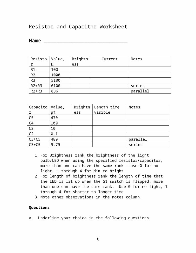
Capacitor Value, μf Brightness Length time visible NotesC5 470C4 100C3 10C2 0.1C3+C5 480 parallelC3+C5 9.79 series
1. For Brightness rank the brightness of the light bulb/LED when using the specified resistor/capacitor, more than one can have the same rank – use 0 for no light, 1 through 4 for dim to bright.
2. For length of brightness rank the length of time that the LED is lit up when the S1 switch is flipped, more than one can have the same rank. Use 0 for no light, 1 through 4 for shorter to longer time.
3. Note other observations in the notes column.
Questions
A. Underline your choice in the following questions.1. The higher the resistance, the (dimmer, brighter) the LED light.2. The higher the capacitance the (dimmer, brighter) the LED light.3. Resistors in parallel give a (dimmer, brighter) LED light.4. Capacitors in parallel give a (dimmer, brighter) light.
B. Use the symbols for a resistor (/\/\/ ) and a capacitor ( || ), and draw a circuit for each one. Which one will cause the LED light to be brighter?
4
Resistor and Capacitor WorksheetAnswer Sheet
Resistor Value Brightness Current NotesR1 100 4 10 mAR2 1000 or 1k 3 3 mAR3 10000 or 10k 2 0.3 mAR2+R3 1100 or 1.1k 2 .25 mA SeriesR2+R3 90.90909… 3 2 mA Parallel
Capacitor Value, μf Brightness Length visible
Notes
C5 470 4 3C4 100 3 2C3 10 2 1C2 0.1 0,None 0,None Does not light upC3+C5 480 4 3 ParallelC3+C5 9.79 2 1 series
1. For Brightness rank the brightness of the light bulb/LED when using the specified resistor/capacitor, more than one can have the same rank. Use 0 for no light, 1-4 for dim to bright.
2. For length of brightness rank the length of time that the LED is lit up when the S1 switch is flipped, more than one can have the same rank. Use 0 for no light, 1-4 for shorter to longer time.
3. Note other observations in the notes column.
Questions A. Underline your choice in the following questions.
1. The higher the resistance, the (dimmer, brighter) the LED light.2. The higher the capacitance the (dimmer, brighter) the LED light.3. Resistors in parallel give a (dimmer, brighter) LED light.4. Capacitors in parallel give a (dimmer, brighter) light.
B. Use the symbols for a resistor (/\/\/ ) and a capacitor ( || ), and draw a circuit for each one. Which one will cause the LED light to be brighter?
The capacitor circuit will give a brighter LED light.
5
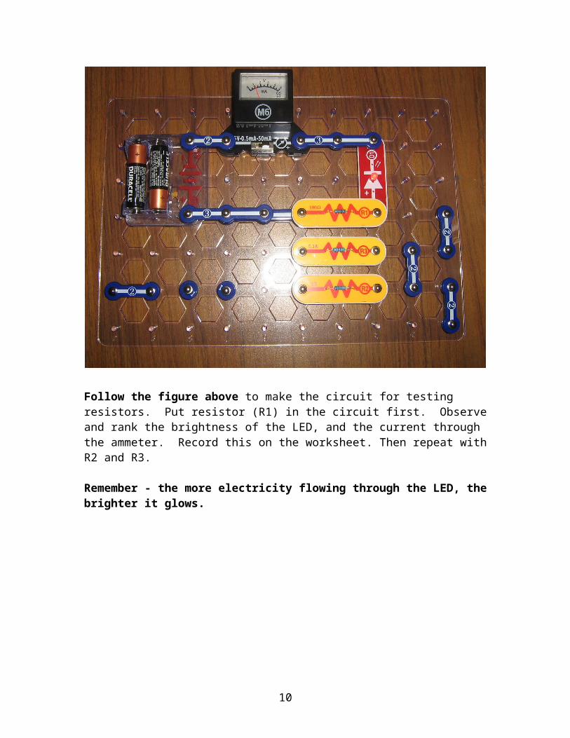
II. A – Different Resistors (Diagram 1)
Follow the figure above to make the circuit for testing resistors. Put resistor (R1) in the circuit first. Observe and rank the brightness of the LED, and the current through the ammeter. Record this on the worksheet. Then repeat with R2 and R3.
Remember - the more electricity flowing through the LED, the brighter it glows.
6
II. B.1 - Resistors in Parallel (Diagram 2)
Follow figure above. Connect the R2 and R3 as shown above. This will place the resistors in parallel. Observe and rank the brightness of the LED and the current through the ammeter. Record this on the worksheet.
7
Note: use the Number 1 Snaps underneath to complete the circuit
II.B.2 – Resistors in Series (Diagram 3)
Follow figure above. Connect R1 and R2 as shown above. This will place the resistors in series. Observe and rank the brightness of the LED and the current through the ammeter. Record this on the worksheet.
8
III.A. Different Capacitors (Diagram 4)
Follow figure aboveStart with the circuit as shown with the C4 capacitor being tested. Be sure the slide switch is off. Hold the push switch down for a few seconds, then release. Then, while carefully watching the LED, turn the slide switch on. You should observe a brief lighting of the LED. Record both the relative brightness and the length of time on the worksheet. Repeat several times to make sure you have observed the light and time properly. Then remove C4 from the circuit and place C3 in the circuit. Repeat the procedure, noting brightness and length of time on your worksheet. Follow the same procedure for C5 and C2,
By adding the capacitors one by one to the circuit and pressing the S2 switch with the S1 switch off, each capacitor can be charged. Then when the S1 switch is turned on the capacitor will discharge and the LED light up until there is no voltage left.
9
III.B.1 Testing Capacitors in Parallel (Diagram 5)
Follow the figure aboveCharge the capacitors as before by pressing down S2, the push switch. Then release and turn on the slide switch, S1. Record your observations on the worksheet.
10
Note: use the Number 1 Snaps underneath to complete the circuit
III.B.2. Testing Capacitors in Series (Diagram 6)
Follow the figure above – charge the capacitors by pressing the S2 switch, then release.Observe the relative brightness and length of time the LED is lit when the S1 switch isturned on. Record your observations on the worksheet.