Page 1
© James P.G. SterbenzITTC
15 November 2017 © 2004–2017 James P.G. Sterbenzrev. 17.0
Communication NetworksThe University of Kansas EECS 780
Physical Layer
James P.G. Sterbenz
Department of Electrical Engineering & Computer Science
Information Technology & Telecommunications Research Center
The University of Kansas
[email protected]
http://www.ittc.ku.edu/~jpgs/courses/hsnets
Page 2
© James P.G. SterbenzITTC
15 November 2017 KU EECS 780 – Comm Nets – Physical Layer NET-PL-2
Communication NetworksPhysical Layer
PL.1 Line Coding
PL.2 Signals and transmission
PL.3 Physical media
PL.4 Performance characteristics
Page 3
© James P.G. SterbenzITTC
15 November 2017 KU EECS 780 – Comm Nets – Physical Layer NET-PL-3
Physical LayerPhysical Layer Communication
• Physical layer
– is responsible for moving bits through a channel
network
application
session
transport
network
link
end system
network
link
node
network
link
nodenetwork
link
node
application
session
transport
network
link
end system
Page 4
© James P.G. SterbenzITTC
15 November 2017 KU EECS 780 – Comm Nets – Physical Layer NET-PL-4
Physical LayerPhysical Layer Communication
• Physical layer communicates digital information
– through a communication channel in a medium
– digital bits are coded as electronic or photonic signals
• digital or analog coding
– over a link between nodes (layer 2)
networkCPU
M app
end system
CPU
M app
end system
R =
D = 0
Page 5
© James P.G. SterbenzITTC
15 November 2017 KU EECS 780 – Comm Nets – Physical Layer NET-PL-5
Physical LayerLine Coding
PL.1 Line coding
PL.2 Signals and Transmission
PL.3 Physical media
PL.4 Performance characteristics
Page 6
© James P.G. SterbenzITTC
15 November 2017 KU EECS 780 – Comm Nets – Physical Layer NET-PL-6
Physical LayerLine Coding and Symbol Rate
• Digital Communication
– we consider only digital communication for networking
• transmission of binary data (bits) through a channel
• Line coding
– way in which bits are encoded for transmission
– digital codes (binary, trinary, …)
– analog modulation
• Symbol rate
– baud rate [symbols/s]
• baud = b/s only if one symbol/bit
– clever encodings (e.g. QAM) allow high baud rates
Page 7
© James P.G. SterbenzITTC
15 November 2017 KU EECS 780 – Comm Nets – Physical Layer NET-PL-7
Line CodingDigital Code Types
• Code
– level code
• symbol depends on the voltage level (amplitude)
– transition code
• symbol depends on transition between levels
– differential code
• symbol depends on difference from last symbol
– level or transition
• Polarity in electrical codes
– unipolar: transitions between 0 and nonzero voltage
– bipolar: transitions between a positive and negative voltage
Page 8
© James P.G. SterbenzITTC
15 November 2017 KU EECS 780 – Comm Nets – Physical Layer NET-PL-8
Digital Line CodingBinary Codes
• Binary line coding:
– two voltage levels: high and low
– bit rate = baud rate
• Binary amplitude code– 0 = low, 1 = high
– clock rate = bit rate
problems?
0 0 1 0 0 1 0 1 1 1
Page 9
© James P.G. SterbenzITTC
15 November 2017 KU EECS 780 – Comm Nets – Physical Layer NET-PL-9
Digital Line CodingBinary Codes
• Binary line coding:
– two voltage levels: high and low
– bit rate = baud rate
• Binary amplitude code– 0 = low, 1 = high
– clock rate = bit rate
– problems: long runs of 0 or 1
• DC bias
• insufficient transitions for clock synchronisation
0 0 1 0 0 1 0 1 1 1
Page 10
© James P.G. SterbenzITTC
15 November 2017 KU EECS 780 – Comm Nets – Physical Layer NET-PL-10
Digital Line CodingBinary Codes
• Binary line coding:
– two voltage levels: high and low
– bit rate = baud rate
• Binary amplitude code– 0 = low, 1 = high
– clock rate = bit rate
– problems: long runs of 0 or 1
• DC bias
• insufficient transitions for clock synchronisation
Alternatives?properties?
0 0 1 0 0 1 0 1 1 1
Page 11
© James P.G. SterbenzITTC
15 November 2017 KU EECS 780 – Comm Nets – Physical Layer NET-PL-11
Digital Line CodingBinary Codes
• Binary line coding:
– two voltage levels: high and low
– bit rate = baud rate
• Binary amplitude code– 0 = low, 1 = high
• Manchester coding– 0 = lowhigh
0 0 1 0 0 1 0 1 1 1
Page 12
© James P.G. SterbenzITTC
15 November 2017 KU EECS 780 – Comm Nets – Physical Layer NET-PL-12
Digital Line CodingBinary Codes
• Binary line coding:
– two voltage levels: high and low
– bit rate = baud rate
• Binary amplitude code– 0 = low, 1 = high
• Manchester coding– 0 = lowhigh 1 = highlow
– clock rate = 2 × bit rate
– no DC bias
– ensures at least one transition per clock cycle
0 0 1 0 0 1 0 1 1 1
Page 13
© James P.G. SterbenzITTC
15 November 2017 KU EECS 780 – Comm Nets – Physical Layer NET-PL-13
Digital Line CodingBinary Codes
• Binary line coding:
– two voltage levels: high and low
– bit rate = baud rate
• Binary amplitude code– 0 = low, 1 = high
• Manchester coding– 0 = lowhigh 1 = highlow
• Differential Manchester coding– transition=0, none=1
0 0 1 0 0 1 0 1 1 1
Page 14
© James P.G. SterbenzITTC
15 November 2017 KU EECS 780 – Comm Nets – Physical Layer NET-PL-14
Line CodingAnalog Coding
• Analog line coding
– modulate an analog carrierwith a digital signal
0 0 1 0 0 1 0 1 1 1
Page 15
© James P.G. SterbenzITTC
15 November 2017 KU EECS 780 – Comm Nets – Physical Layer NET-PL-15
Analog Line CodingAmplitude Modulation
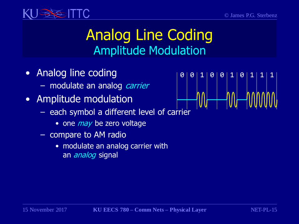
• Analog line coding
– modulate an analog carrier
• Amplitude modulation
– each symbol a different level of carrier
• one may be zero voltage
– compare to AM radio
• modulate an analog carrier withan analog signal
0 0 1 0 0 1 0 1 1 1
Page 16
© James P.G. SterbenzITTC
15 November 2017 KU EECS 780 – Comm Nets – Physical Layer NET-PL-16
Analog Line CodingFrequency Modulation
• Analog line coding
– modulate a carrier
• Amplitude modulation
– each symbol a different level
• Frequency modulation
– each symbol a different frequency
– FSK (frequency shift keying)
– compare to FM radio
• modulate an analog carrier withan analog signal
0 0 1 0 0 1 0 1 1 1
Page 17
© James P.G. SterbenzITTC
15 November 2017 KU EECS 780 – Comm Nets – Physical Layer NET-PL-17
Analog Line CodingV.21 AFSK
• AFSK analog modem line coding
– AFSK (audio frequency shift keying)
– modem (modulate / demodulate)
• ITU V.21 300 baud = 300b/s (1964 – 1980s)
– full duplex: one channel for each direction
– frequencies within audio spectrum of POTS telephone line
why?
Page 18
© James P.G. SterbenzITTC
15 November 2017 KU EECS 780 – Comm Nets – Physical Layer NET-PL-18
Analog Line CodingV.21 AFSK
• AFSK analog modem line coding
– AFSK (audio frequency shift keying)
– modem (modulate / demodulate)
• ITU V.21 300 baud = 300b/s (1964 – 1980s)
– full duplex: one channel for each direction
– frequencies within audio spectrum of POTS telephone line
• motivation: transport data over existing phone lines
• old timers recall modem squeal
Channel Carrier 0 Symbol 1 Symbol
1 1080 Hz 1180 Hz 980 Hz
2 1750 Hz 1850 Hz 1650 Hz
Page 19
© James P.G. SterbenzITTC
15 November 2017 KU EECS 780 – Comm Nets – Physical Layer NET-PL-19
Analog Line CodingDTMF
• DTMF (dual tone multi-frequency)
– AMFSK (audio multi-frequency shift keying)
• PSTN in-band signalling
– handset (user–network) and network–network
• Design goals
– within PSTN audio spectrum
– not a binary code: symbols include all decimal numbers
– MPSK
• multiple frequencies
• two frequencies per symbol
• avoid harmonics that could lead to false symbol decoding
Page 20
© James P.G. SterbenzITTC
15 November 2017 KU EECS 780 – Comm Nets – Physical Layer NET-PL-20
Analog Line CodingDTMF
• DTMF (dual tone multi-frequency)
– AMFSK (audio multi-frequency shift keying)
• PSTN in-band signalling
440 Hz 480 Hz 620 Hz 1209 Hz 1336 Hz 1477 Hz 1633 Hz
350 Hz dial tone
440 Hz ringback
480 Hz ringback busy
697 Hz 1 2 3 A
770 Hz 4 5 6 B
852 Hz 7 8 9 C
941 Hz * 0 # D
Page 21
© James P.G. SterbenzITTC
15 November 2017 KU EECS 780 – Comm Nets – Physical Layer NET-PL-21
Analog Line CodingPhase Modulation
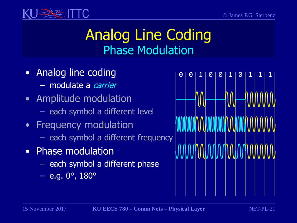
• Analog line coding
– modulate a carrier
• Amplitude modulation
– each symbol a different level
• Frequency modulation
– each symbol a different frequency
• Phase modulation
– each symbol a different phase
– e.g. 0°, 180°
0 0 1 0 0 1 0 1 1 1
Page 22
© James P.G. SterbenzITTC
15 November 2017 KU EECS 780 – Comm Nets – Physical Layer NET-PL-22
Analog Line CodingV.21 AFSK
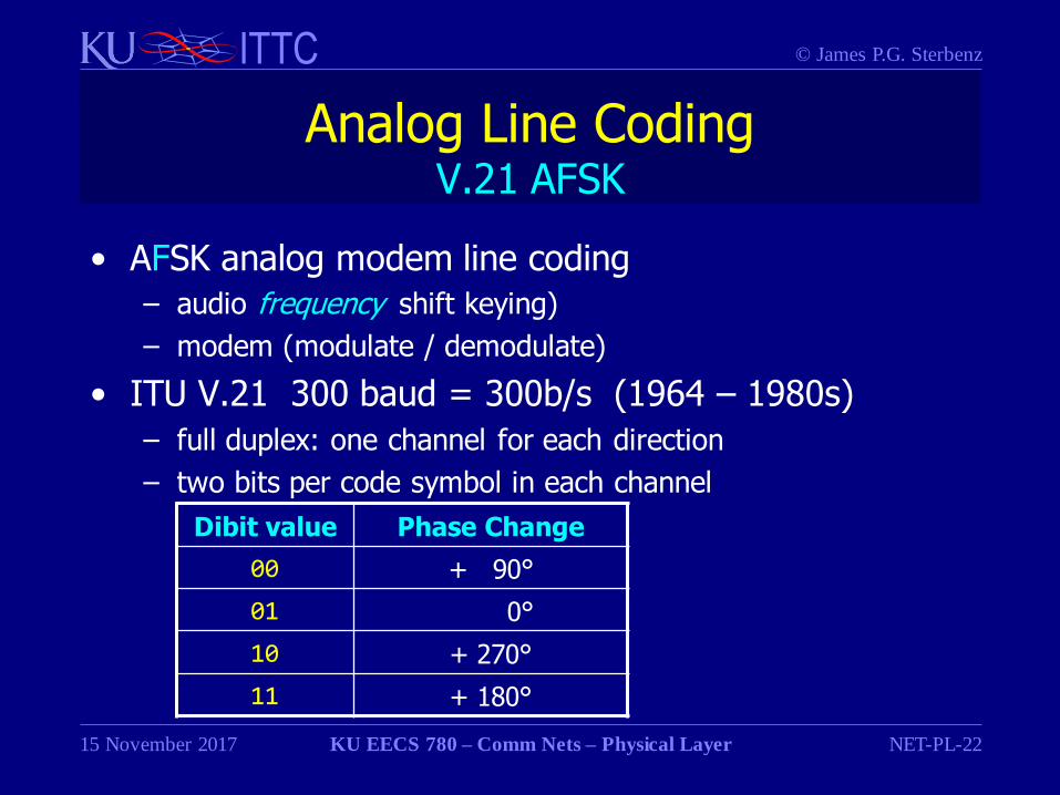
• AFSK analog modem line coding
– audio frequency shift keying)
– modem (modulate / demodulate)
• ITU V.21 300 baud = 300b/s (1964 – 1980s)
– full duplex: one channel for each direction
– two bits per code symbol in each channel
Dibit value Phase Change
00 + 90°
01 0°
10 + 270°
11 + 180°
Page 23
© James P.G. SterbenzITTC
15 November 2017 KU EECS 780 – Comm Nets – Physical Layer NET-PL-23
Analog Line CodingV.22 APSK
• APSK analog modem line coding
– audio phase shift keying)
– modem (modulate / demodulate)
• ITU V.22 600 baud = 1200b/s (1980)
– full duplex: one channel for each direction
• frequencies within audio spectrum of POTS telephone line
• 1200 Hz and 2400 Hz channels
– two bits per code symbol in each channel
• bit rate = 2 × symbol rate
Page 24
© James P.G. SterbenzITTC
15 November 2017 KU EECS 780 – Comm Nets – Physical Layer NET-PL-24
Analog Line CodingCombination Codes
• Analog line coding:
– modulate a carrier
• Amplitude modulation
– each symbol a different level
• Frequency modulation
– each symbol a different frequency
• Phase modulation
– each symbol a different phase
• Combinations possible
why?
0 0 1 0 0 1 0 1 1 1
Page 25
© James P.G. SterbenzITTC
15 November 2017 KU EECS 780 – Comm Nets – Physical Layer NET-PL-25
Analog Line CodingCombination Codes
• Analog line coding:
– modulate a carrier
• Amplitude modulation
– each symbol a different level
• Frequency modulation
– each symbol a different frequency
• Phase modulation
– each symbol a different phase
• Combinations possible
– e.g. amplitude and phase
0 0 1 0 0 1 0 1 1 1
00 10 01 01 11 00 10 01 01 11
Page 26
© James P.G. SterbenzITTC
15 November 2017 KU EECS 780 – Comm Nets – Physical Layer NET-PL-26
Analog Line CodingPAM
• PAM: pulse amplitude modulation
– n bits coded in 2n amplitudes per symbol
– PAM-5 in 1GBaseT for CAT-5 100MHz frequency limit
Name Amplitudes Phases Bits/Symbol
PAM-4 4 1 2
PAM-5 5 1 2 + error
PAM-8 8 1 4
PAM-16 16 1 5
Page 27
© James P.G. SterbenzITTC
15 November 2017 KU EECS 780 – Comm Nets – Physical Layer NET-PL-27
Analog Line CodingQPSK and QAM
• Combination of amplitude- and phase-modulation
– allows more bits per symbol
• QAM: quadrature amplitude modulation
– quadrature = 4 phases carried on two sine waves
– PAM is case for only one phase
– QPSK is case for only one amplitude
Name Amplitudes Phases Bits/Symbol
QPSK 1 4 2
QAM-16 2 4 4
QAM-64 3 4 6
QAM-256 4 4 8
Page 28
© James P.G. SterbenzITTC
15 November 2017 KU EECS 780 – Comm Nets – Physical Layer NET-PL-28
Analog Line CodingQPSK and QAM
• QAM: amplitude- and phase modulation
• Represented by constellation diagram– amplitude is distance from origin
– phase is angle
0°180°
90°
270°
0°180°
90°
270°
0°180°
90°
270°
QAM-64QAM-16QPSK
Page 29
© James P.G. SterbenzITTC
15 November 2017 KU EECS 780 – Comm Nets – Physical Layer NET-PL-29
Analog Line CodingModem Standards Summary1
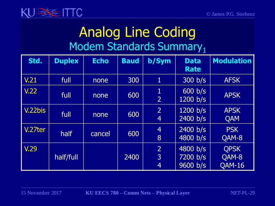
Std. Duplex Echo Baud b/Sym Data Rate
Modulation
V.21 full none 300 1 300 b/s AFSK
V.22full none 600
12
600 b/s1200 b/s
APSK
V.22bisfull none 600
24
1200 b/s2400 b/s
APSKQAM
V.27terhalf cancel 600
48
2400 b/s4800 b/s
PSKQAM-8
V.29half/full 2400
234
4800 b/s7200 b/s9600 b/s
QPSKQAM-8QAM-16
Page 30
© James P.G. SterbenzITTC
15 November 2017 KU EECS 780 – Comm Nets – Physical Layer NET-PL-30
Analog Line CodingModem Standards Summary2
Std. Duplex Echo Baud b/Sym Data Rate
Modulation
V32 half/full cancel 2400 1 300 b/s AFSK
V.32bisfull none 600
12
600 b/s1200 b/s
APSK
V.34full none 600
24
1200 b/s2400 b/s
APSKQAM
V.34bishalf cancel 600
48
2400 b/s4800 b/s
PSKQAM-8
V.90
V.92half/full 2400
234
4800 b/s7200 b/s9600 b/s
QPSKQAM-8QAM-16
Page 31
© James P.G. SterbenzITTC
15 November 2017 KU EECS 780 – Comm Nets – Physical Layer NET-PL-31
Physical LayerPL.2 Signals and Transmission
PL.1 Line coding
PL.2 Signals and transmission
PL.3 Physical media
PL.4 Performance characteristics
Page 32
© James P.G. SterbenzITTC
15 November 2017 KU EECS 780 – Comm Nets – Physical Layer NET-PL-32
CommunicationSignal Types
• Transmission of a signal through a medium
Page 33
© James P.G. SterbenzITTC
15 November 2017 KU EECS 780 – Comm Nets – Physical Layer NET-PL-33
CommunicationSignal Types
• Transmission of a signal through a medium
• Analog signal: time-varying levels– electrical: voltage levels
– photonic: light intensity
Page 34
© James P.G. SterbenzITTC
15 November 2017 KU EECS 780 – Comm Nets – Physical Layer NET-PL-34
CommunicationSignal Types
• Transmission of a signal through a medium
• Analog signal: time-varying levels– electrical: voltage levels
– photonic: light intensity
• Digital signal: sequence of bits represented as levels
– electrical: voltage pulses
– photonic: light pulses
– two levels for binary digital signal
– more levels in some coding schemes more later
Page 35
© James P.G. SterbenzITTC
15 November 2017 KU EECS 780 – Comm Nets – Physical Layer NET-PL-35
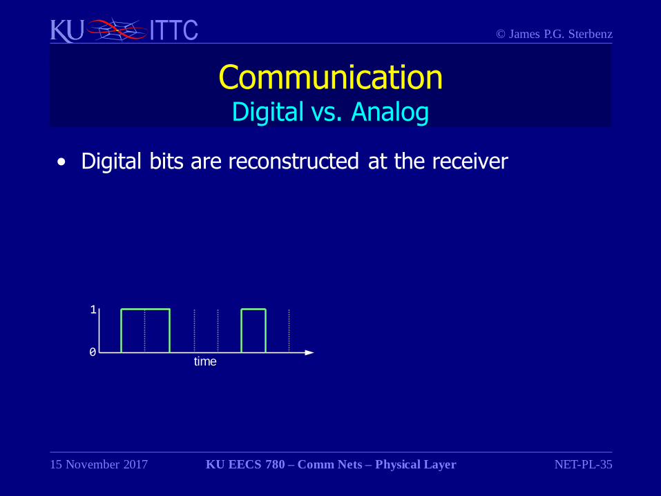
CommunicationDigital vs. Analog
• Digital bits are reconstructed at the receiver
0
1
time
Page 36
© James P.G. SterbenzITTC
15 November 2017 KU EECS 780 – Comm Nets – Physical Layer NET-PL-36
CommunicationDigital vs. Analog
• Digital bits are reconstructed at the receiver
– all transmission is actually analog!
– frequency response determines
• pulse rate that can be transmitted
• shape of pulse ability for receiver to recognise pulse
0
1
time
Page 37
© James P.G. SterbenzITTC
15 November 2017 KU EECS 780 – Comm Nets – Physical Layer NET-PL-37
CommunicationDigital vs. Analog
• Digital bits are reconstructed at the receiver
– all transmission is actually analog!
– frequency response determines
• pulse rate that can be transmitted
• shape of pulse ability for receiver to recognise pulse
– high-frequency attenuation reduces quality of pulse
0
1
0
1
harmonic
harmonic
time
time
attenuated frequencies
adapted from [Tanenbaum 2003]
Page 38
© James P.G. SterbenzITTC
15 November 2017 KU EECS 780 – Comm Nets – Physical Layer NET-PL-38
CommunicationMedium Types
• Guided through waveguide
– wire (generally copper)
– fiber optic cable
Page 39
© James P.G. SterbenzITTC
15 November 2017 KU EECS 780 – Comm Nets – Physical Layer NET-PL-39
CommunicationMedium Types
• Guided through waveguide
– wire (generally copper)
– fiber optic cable
• Unguided (wireless) free space propagation
– wireless
(generally implying RF – radio frequency)
• free-space optical
Page 40
© James P.G. SterbenzITTC
15 November 2017 KU EECS 780 – Comm Nets – Physical Layer NET-PL-40
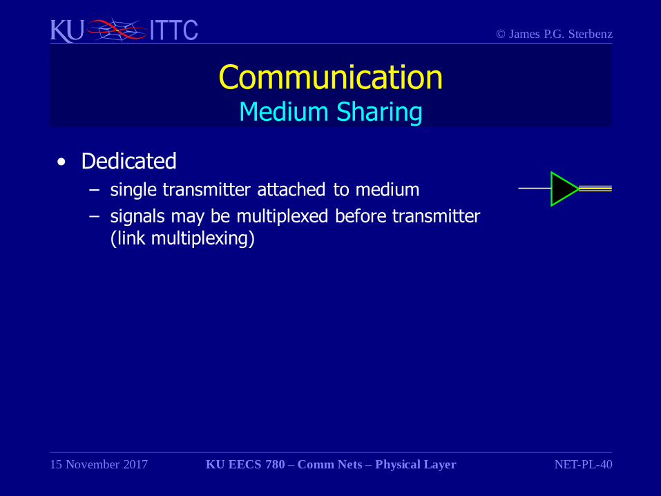
CommunicationMedium Sharing
• Dedicated
– single transmitter attached to medium
– signals may be multiplexed before transmitter(link multiplexing)
Page 41
© James P.G. SterbenzITTC
15 November 2017 KU EECS 780 – Comm Nets – Physical Layer NET-PL-41
CommunicationMedium Sharing
• Dedicated
– single transmitter attached to medium
– signals may be multiplexed by a single transmitter
• link multiplexing
• Shared: multiple access
– multiple transmitters transmit into a the same medium
free space RF
Page 42
© James P.G. SterbenzITTC
15 November 2017 KU EECS 780 – Comm Nets – Physical Layer NET-PL-42
CommunicationChallenges1
• Goal: receiver reconstruct signal transmitter sent
Page 43
© James P.G. SterbenzITTC
15 November 2017 KU EECS 780 – Comm Nets – Physical Layer NET-PL-43
CommunicationChallenges1
• Goal: receiver reconstruct signal transmitter sent
• Noise makes this difficult– background noise No interferes with the signal bit energy Eb
• SNR: signal to noise ratio = 10 log10 (Eb /No ) dB
– interference from other signals in shared medium• collisions among multiple transmitters
• jamming from adversaries
– imperfections in the physical medium that alters the signal• especially in fiber optic cables
Page 44
© James P.G. SterbenzITTC
15 November 2017 KU EECS 780 – Comm Nets – Physical Layer NET-PL-44
CommunicationChallenges1
• Goal: receiver reconstruct signal transmitter sent
• Noise makes this difficult– background noise No interferes with the signal bit energy Eb
• SNR: signal to noise ratio = 10 log10 (Eb /No ) dB
– interference from other signals in shared medium• collisions among multiple transmitters
• jamming from adversaries
– imperfections in the physical medium that alters the signal• especially in fiber optic cables
• Attenuation over distance that reduces the amplitude– 10 log10 (Et /Er ) dB
Page 45
© James P.G. SterbenzITTC
15 November 2017 KU EECS 780 – Comm Nets – Physical Layer NET-PL-45
CommunicationChallenges1
• Goal: receiver reconstruct signal transmitter sent
• Noise makes this difficult– background noise No interferes with the signal bit energy Eb
• SNR: signal to noise ratio = 10 log10 (Eb /No ) dB
– interference from other signals in shared medium• collisions among multiple transmitters
• jamming from adversaries
– imperfections in the physical medium that alters the signal• especially in fiber optic cables
• Attenuation over distance that reduces the amplitude– 10 log10 (Et /Er ) dB
• Frequency response of the medium
Page 46
© James P.G. SterbenzITTC
15 November 2017 KU EECS 780 – Comm Nets – Physical Layer NET-PL-46
CommunicationChallenges2
• Result: difficulty in reconstructing signal
Page 47
© James P.G. SterbenzITTC
15 November 2017 KU EECS 780 – Comm Nets – Physical Layer NET-PL-47
CommunicationChallenges2
• Result: difficulty in reconstructing signal
• Analog: distortion of received waveforms
Page 48
© James P.G. SterbenzITTC
15 November 2017 KU EECS 780 – Comm Nets – Physical Layer NET-PL-48
CommunicationChallenges2
• Result: difficulty in reconstructing signal
• Analog: distortion of received waveforms
• Digital: bit errors – an artifact of distortion
– distance attenuation reduces level of pulse
– frequency attenuation distorts shape of pulse
– distortion changes shape of pulse
– dispersion smears pulses
Page 49
© James P.G. SterbenzITTC
15 November 2017 KU EECS 780 – Comm Nets – Physical Layer NET-PL-49
CommunicationChallenges2
• Result: difficulty in reconstructing signal
• Analog: distortion of received waveforms
• Digital: bit errors – an artifact of distortion
– distance attenuation reduces level of pulse
– frequency attenuation distorts shape of pulse
– distortion changes shape of pulse
– dispersion smears pulses
• Physical and link layer devices help
– amplifiers ameliorate attenuation
– regenerators and repeaters reconstruct digital signals
• spaced closely enough to keep bit error rate low
Page 50
© James P.G. SterbenzITTC
15 November 2017 KU EECS 780 – Comm Nets – Physical Layer NET-PL-50
Physical LayerPL.32 Physical Media
PL.1 Line coding
PL.2 Signals and transmission
PL.3 Physical media
PL.4 Performance characteristics
Page 51
© James P.G. SterbenzITTC
15 November 2017 KU EECS 780 – Comm Nets – Physical Layer NET-PL-51
Physical MediaWire
• Unshielded twisted pair
– cheap, moderate bandwidth (~100Mb/s)
– and increasing with more sophisticated coding techniques
• Shielded twisted pair
– expensive, higher bandwidth
• Coaxial cable
– expensive, high bandwidth (~ 500 MHz)
Page 52
© James P.G. SterbenzITTC
15 November 2017 KU EECS 780 – Comm Nets – Physical Layer NET-PL-52
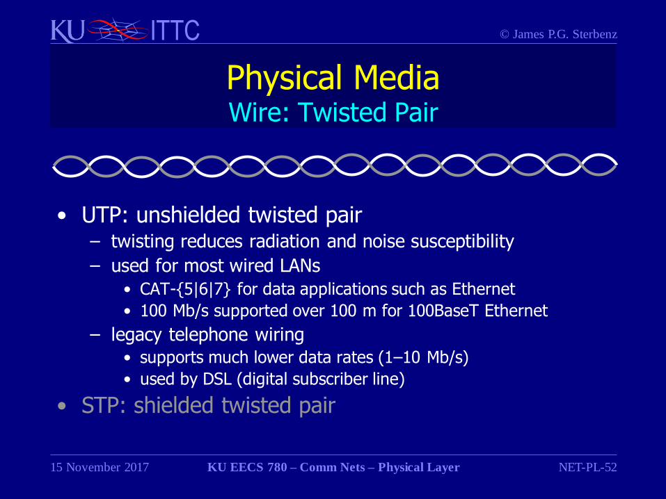
Physical MediaWire: Twisted Pair
• UTP: unshielded twisted pair– twisting reduces radiation and noise susceptibility
– used for most wired LANs
• CAT-{5|6|7} for data applications such as Ethernet
• 100 Mb/s supported over 100 m for 100BaseT Ethernet
– legacy telephone wiring• supports much lower data rates (1–10 Mb/s)
• used by DSL (digital subscriber line)
• STP: shielded twisted pair
Page 53
© James P.G. SterbenzITTC
15 November 2017 KU EECS 780 – Comm Nets – Physical Layer NET-PL-53
Physical MediaWire: Shielded Twisted Pair
• UTP: unshielded twisted pair
• STP: shielded twisted pair– adds conducting shield outside of twisted pair
– more resistant to noise than UTP
– more expensive than UTP
– used in IBM Token Ring LANs
– no longer commonly used
Page 54
© James P.G. SterbenzITTC
15 November 2017 KU EECS 780 – Comm Nets – Physical Layer NET-PL-54
Physical MediaWire: TP Types
Category Type BW Application Range
Cat 3 UTP 16 MHz telephone
Cat 5UTP 100 MHz
10BaseT100BaseT
100m
Cat 5e UTP 100 MHz 100BaseT 100m
Cat 6UTP 250 MHz
1GBaseT 10GBaseT
100m55m
Cat 6A U/FTP F/UTP 500 MHz cf 100m
Cat 7 F/FTP S/FTP 1 GHz
Cat 7A F/FTP S/FTP 1 GHz
Cat 8half/full
2 GHz 40GBaseT
Page 55
© James P.G. SterbenzITTC
15 November 2017 KU EECS 780 – Comm Nets – Physical Layer NET-PL-55
Physical MediaWire: Coaxial Cable
• High quality shielded cable
– used in some LANs (and early Ethernet)
– used in CATV (RG6 better than RG59)
• HFC: hybrid fiber coax for data
Cu
conductor dielectric
insulatorshield insulating
jacket
Page 56
© James P.G. SterbenzITTC
15 November 2017 KU EECS 780 – Comm Nets – Physical Layer NET-PL-56
Physical MediaFiber Optics
• Fiber optics
– bandwidth 20 THz within 800–1700 nm
– attenuation [dB/km]
– dispersion: waveform smearing limits bandwidth--distance
Much more about optical communication in EECS 881
Page 57
© James P.G. SterbenzITTC
15 November 2017 KU EECS 780 – Comm Nets – Physical Layer NET-PL-57
Physical MediaFiber Optic Cable
• Lightwave travels along glass or plastic core
– multimode: reflected along core/cladding boundary
– single mode: guided with no reflections
• Transmitter
– LED or solid-state laser
glass or
plastic core glass or
plastic
cladding
insulating
jacket
Page 58
© James P.G. SterbenzITTC
15 November 2017 KU EECS 780 – Comm Nets – Physical Layer NET-PL-58
Physical MediaFiber Optic Modes
• Multimode: 50 – 85 m core
– signal reflected in multiple modes
– intermodal dispersion limits length to a few km
why?
reflections
transmitted signal
Page 59
© James P.G. SterbenzITTC
15 November 2017 KU EECS 780 – Comm Nets – Physical Layer NET-PL-59
Physical MediaFiber Optic Modes
• Multimode: 50 – 85 m core
– signal reflected in multiple modes
– intermodal dispersion limits length to a few km
• different modes arrive at different times
consequence?
reflections
mode x
mode ytransmitted signal
Page 60
© James P.G. SterbenzITTC
15 November 2017 KU EECS 780 – Comm Nets – Physical Layer NET-PL-60
Physical MediaFiber Optic Modes
• Multimode: 50 – 85 m core
– signal reflected in multiple modes
– intermodal dispersion limits length to a few km
• different modes arrive at different times
• received signal is sum of modes
reflections
mode x
mode ytransmitted signal received signal
= x+y
Page 61
© James P.G. SterbenzITTC
15 November 2017 KU EECS 780 – Comm Nets – Physical Layer NET-PL-61
Physical MediaFiber Optic Modes
• Multimode: 50 – 85 m core
– signal reflected in multiple modes
– intermodal dispersion limits length to a few km
why?
• Single mode: 8–10 m core
– core acts as waveguide with no reflections
– suitable for 10s of km between digital regenerators
reflections
Page 62
© James P.G. SterbenzITTC
15 November 2017 KU EECS 780 – Comm Nets – Physical Layer NET-PL-62
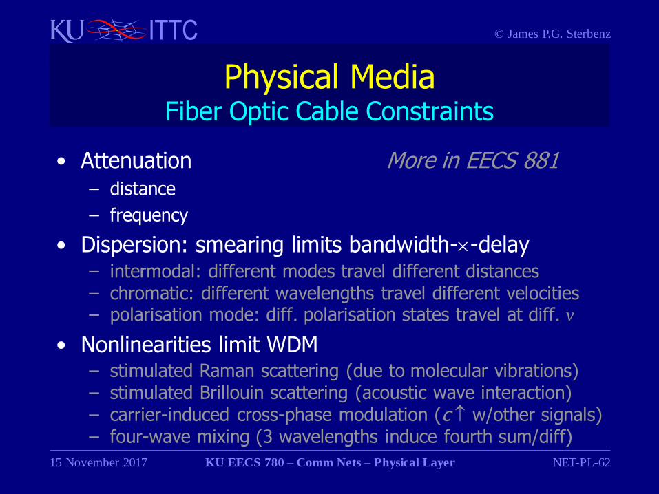
Physical MediaFiber Optic Cable Constraints
• Attenuation More in EECS 881– distance
– frequency
• Dispersion: smearing limits bandwidth--delay– intermodal: different modes travel different distances– chromatic: different wavelengths travel different velocities– polarisation mode: diff. polarisation states travel at diff. v
• Nonlinearities limit WDM– stimulated Raman scattering (due to molecular vibrations)– stimulated Brillouin scattering (acoustic wave interaction)– carrier-induced cross-phase modulation (c w/other signals)– four-wave mixing (3 wavelengths induce fourth sum/diff)
Page 63
© James P.G. SterbenzITTC
15 November 2017 KU EECS 780 – Comm Nets – Physical Layer NET-PL-63
Physical MediaWireless Free Space
• Signals transmitted through free space
– no waveguide
• Spectrum (f = c ; c = 3105 km/s)
– only some spectrum usable for communication
– RF: radio frequency
– optical
• infrared 800–900 nm = 333–375 THz 41 THz spectrum
Much more about wireless communication in EECS 882[http://www.ntia.doc.gov/osmhome/allochrt.pdf]
Page 64
© James P.G. SterbenzITTC
15 November 2017 KU EECS 780 – Comm Nets – Physical Layer NET-PL-64
Wireless Free SpaceSpectrum
Band Range Propagation Usage Examples
Name Description Frequencies Wavelength Sight Attenuation
ELF ext. low 30– 300 Hz 10– 1Mm GW home automation
VF voice 300–3000 Hz 1000–100km GW voice tel., modem
VLF very low 3– 30kHz 100– 10km GW atmos. noise submarine
LF low 30– 300kHz 10– 1km GW daytime maritime
MF medium 300–3000kHz 1000–100 m GW daytime maritime, AM radio
HF high 3 – 30MHz 100– 10 m SW daytime transportation
VHF very high 30 –300MHz 10– 1 m LOS temp, cosmic television, FM radio
UHF ultra high 300–3000MHz 1000–100mm LOS cosmic noise TV, cell tel, LAN/MAN
SHF super high 3 –30GHz 100– 10mm LOS O2, H2O p2p µwave, LAN/MAN
EHF ext. high 30–300GHz 10– 1mm LOS O2, H2O vapor wireless LAN/MAN
IR infrared 300GHz–400THz 1000–770nm LOS optical comm
visible visible 400–900THz 770–330 nm LOS
Page 65
© James P.G. SterbenzITTC
15 November 2017 KU EECS 780 – Comm Nets – Physical Layer NET-PL-65
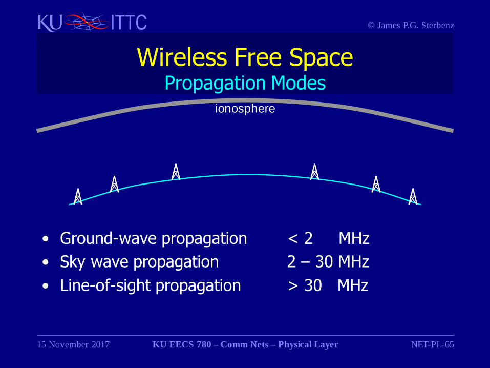
Wireless Free SpacePropagation Modes
• Ground-wave propagation < 2 MHz
• Sky wave propagation 2 – 30 MHz
• Line-of-sight propagation > 30 MHz
ionosphere
Page 66
© James P.G. SterbenzITTC
15 November 2017 KU EECS 780 – Comm Nets – Physical Layer NET-PL-66
Wireless Free SpacePropagation Modes: Ground Wave
• Ground-wave propagation < 2 MHz
– signals follow curvature of earth
– scattered in upper atmosphere
• Sky wave propagation 2 – 30 MHz
• Line-of-sight propagation > 30 MHz
ionosphere
Page 67
© James P.G. SterbenzITTC
15 November 2017 KU EECS 780 – Comm Nets – Physical Layer NET-PL-67
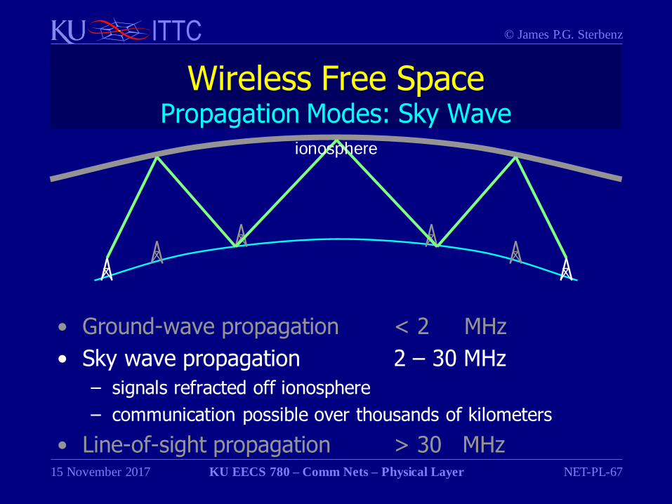
Wireless Free SpacePropagation Modes: Sky Wave
• Ground-wave propagation < 2 MHz
• Sky wave propagation 2 – 30 MHz
– signals refracted off ionosphere
– communication possible over thousands of kilometers
• Line-of-sight propagation > 30 MHz
ionosphere
Page 68
© James P.G. SterbenzITTC
15 November 2017 KU EECS 780 – Comm Nets – Physical Layer NET-PL-68
Wireless Free SpacePropagation Modes: Line of Sight
• Ground-wave propagation < 2 MHz
• Sky wave propagation 2 – 30 MHz
• Line-of-sight propagation > 30 MHz
– antennæ must be in view of one-another
– terrain and earth curvature block signature
ionosphere
Page 69
© James P.G. SterbenzITTC
15 November 2017 KU EECS 780 – Comm Nets – Physical Layer NET-PL-69
Wireless Free SpaceLicensing
• Licensed and regulated spectrum
– ITU (international) and each country (FCC in US) regulate
– most frequency bands require license to transmit
• e.g. broadcast TV, radio, amateur radio, GMRS
– some bands do not require explicit license application
• e.g. US CB (citizen band), FRS (family radio system)
Page 70
© James P.G. SterbenzITTC
15 November 2017 KU EECS 780 – Comm Nets – Physical Layer NET-PL-70
Wireless Free SpaceMicrowave Terrestrial Links
• Microwave links
– typically point-to-point directional links
– once ubiquitous for long-distance telephony
• 4 GHz TD radio and 6 GHz TH radios
• mostly replaced by fiber optic cables in 1980s
– subject to fading during rain storms
• New interest
– local loops and MANs
– backhaul for 3G/4G to fibre infrastructure
– point-to-point links
– mmwave (60–90 GHz) can provide 1–10 Gb/s links
Page 71
© James P.G. SterbenzITTC
15 November 2017 KU EECS 780 – Comm Nets – Physical Layer NET-PL-71
Wireless Free SpaceSatellite Characteristics
• Satellite orbit characteristics
• Tradeoffs
– cost per satellite (GEO), high link power, high delay
– total cost of constellation, constellation management
Type Altitude Constellation Size Link Delay
LEOlow earth orbit
100 km –1 000 km
~50 – 1000 ~1–10 ms
MEOmedium earth orbit
5 000 km –15 000 km
~10 ~35–85 ms
GEOgeosynchronous EO
36786 km3 (plus polar) 270 ms
Page 72
© James P.G. SterbenzITTC
15 November 2017 KU EECS 780 – Comm Nets – Physical Layer NET-PL-72
Wireless Free SpaceMicrowave Satellite Links
• Satellite links
BandTypical Frequency [GHz]
Bandwidth IssuesDownlink Uplink
L 1.5 1.6 15 MHz low aggregate BW
S 1.9 2.2 70 MHz low aggregate BW
C 4.0 6.0 500 MHz terrestrial interference
Ku 11 14 500 MHz rain fade
Ka 20 30 3.5 GHz rain fade
Page 73
© James P.G. SterbenzITTC
15 November 2017 KU EECS 780 – Comm Nets – Physical Layer NET-PL-73
Wireless Free SpaceUnlicensed Spectrum
• Unlicensed spectrum
– regulations for use (FCC 15.243–249)
• e.g. max transmit power
• e.g. spread spectrum parameters
– ISM: industrial, scientific, and medical
• … 900 MHz, 2.4 GHz, 5.8 GHz, 24GHz, 60GHz …
– UNII: unlicensed national information infrastructure
• 5.8 GHz
– may be use by anyone for any purpose (subject to regulations)
problem?
Page 74
© James P.G. SterbenzITTC
15 November 2017 KU EECS 780 – Comm Nets – Physical Layer NET-PL-74
Wireless Free SpaceUnlicensed Spectrum
• Unlicensed spectrum
– regulations for use (FCC 15.243–249)
• e.g. max transmit power
• e.g. spread spectrum parameters
– ISM: industrial, scientific, and medical
• … 900 MHz, 2.4 GHz, 5.8 GHz, 24GHz, 60GHz, …
– UNII: unlicensed national information infrastructure
• 5.8 GHz
– may be use by anyone for any purpose (subject to regulations)
– interference a significant problem
• e.g. 2.4 GHz FHSS cordless phones against 802.11b
• e.g. interference among 802.11 hubs in dense environments
Page 75
© James P.G. SterbenzITTC
15 November 2017 KU EECS 780 – Comm Nets – Physical Layer NET-PL-75
Wireless Free SpaceFCC Spectrum Allocation
• FCC allocates and licenses spectrum in US
– static allocations lead to significant inefficiency in use
[http://www.ntia.doc.gov/osmhome/allochrt.pdf]
ISM 60 GHz
ISM 5.8 GHz
ISM 900 MHz ISM 2.4 GHz
ISM 40 MHz
ISM 24 GHz
ISM 122 GHz ISM 245 GHz
Page 76
© James P.G. SterbenzITTC
15 November 2017 KU EECS 780 – Comm Nets – Physical Layer NET-PL-76
Wireless Free SpaceRF Antennæ and Attenuation
• Antennæ
– omnidirectional: RF radiated in all directions
– directional: focused beam of radiation
• reduces contention and improves spatial reuse
• significantly complicates network design if mobile
– beam steering
• laser/maser: focused coherent light/microwave transmission
• Attenuation
– signal strength decreases as 1/r 2 in perfect medium
– signal may decrease as 1/r x with multipath interference
• rural environments: x > 2
• urban environments: x 4
Page 77
© James P.G. SterbenzITTC
15 November 2017 KU EECS 780 – Comm Nets – Physical Layer NET-PL-77
Physical LayerPerformance Characteristics
PL.1 Signals and transmission
PL.2 Physical media
PL.3 Performance characteristics
PL.4 Line Coding
Page 78
© James P.G. SterbenzITTC
15 November 2017 KU EECS 780 – Comm Nets – Physical Layer NET-PL-78
Physical Media PerformanceVelocity
• Velocity v = c /n [m/s]
– speed of light c = 3105 km/s
– index of refraction n
Consequences?
Page 79
© James P.G. SterbenzITTC
15 November 2017 KU EECS 780 – Comm Nets – Physical Layer NET-PL-79
Physical Media PerformanceVelocity and Delay
• Velocity v = c /n [m/s]
– speed of light c = 3105 km/s
– index of refraction n
• this is why velocity slower than c in fiber and wire
• Delay d = 1/v [s/m]
– generally we will express delay in [s] given a path length
Page 80
© James P.G. SterbenzITTC
15 November 2017 KU EECS 780 – Comm Nets – Physical Layer NET-PL-80
Physical Media PerformanceLink Length
• Link Length
– distance over which signals propagate
• point-to-point: wire or fibre length
• shared medium: longest path
– constrained by physical properties of medium
Consequences?
Page 81
© James P.G. SterbenzITTC
15 November 2017 KU EECS 780 – Comm Nets – Physical Layer NET-PL-81
Physical Media PerformanceLink Length and Attenuation
• Link Length
– distance over which signals propagate
• point-to-point: wire length
• shared medium: longest path
– constrained by physical properties of medium
• Attenuation: decrease in signal intensity• over distance expressed as [dB/m]
• at a particular signal frequency
dB
m
mdB
Page 82
© James P.G. SterbenzITTC
15 November 2017 KU EECS 780 – Comm Nets – Physical Layer NET-PL-82
Physical Media PerformanceFrequency Response and Attenuation
• Frequency range and attenuation
– ability to propagate signals of a given frequency
• Characteristics of guided media
– wire: generally falls off above a certain fmax
– fiber optic cable & free space transparent to certain ranges
analogy:UV blocking sunglasses (high attenuation )
vs.standard glass (moderate attenuation )
vs.UV transparent black light glass (low attenuation )
Page 83
© James P.G. SterbenzITTC
15 November 2017 KU EECS 780 – Comm Nets – Physical Layer NET-PL-83
Physical Media PerformanceFrequency Response and Attenuation: Optical
• Fiber-optic cable transparency bands
– 1300 and 1550 nm
– 850 nm for lower cost
850
nm1300
nm
1550
nm
1.20.8 0.9 1.4 1.6
1
2
0
Atten
uation
[d
B/k
m]
Wavelength [μm] [adapted from Tannenbaum 2003]
Page 84
© James P.G. SterbenzITTC
15 November 2017 KU EECS 780 – Comm Nets – Physical Layer NET-PL-84
Physical Media PerformanceFrequency Response and Attenuation: RF
• Atmospheric transparency bands– RF: 10MHz – 10GHz
• VHF meter band, UHF millimeter band
– Infrared: N-band
RF
0.5
1.0
0.0
Atm
osp
heri
c O
pacity
Wavelength [m] | Frequency [Hz]
10µm0.1nm 10nm 10m 100m 1km1m10cm1cm1mm100µm1µm1nm 100nm
adapted from
[coolcosmos.ipac.caltech.edu/cosmic_classroom/ir_tutorial/irwindows.html]
10THz1EHz 10Pz 10MHz 1MHz 100KHz100MHz1GHz10GHz100GHz1THz100THz100PHz 1PHz
N
UHF VHF
microwave shortwave
Page 85
© James P.G. SterbenzITTC
15 November 2017 KU EECS 780 – Comm Nets – Physical Layer NET-PL-85
Wireless PerformancePropagation Mechanisms
• Direct signal
• Reflection
• Diffraction
• Scattering
WN
Page 86
© James P.G. SterbenzITTC
15 November 2017 KU EECS 780 – Comm Nets – Physical Layer NET-PL-86
Wireless PerformancePropagation Mechanisms: Direct
• Direct signal
– direct transmission from transmitter to receiver
• Reflection
• Diffraction
• Scattering
WN
Page 87
© James P.G. SterbenzITTC
15 November 2017 KU EECS 780 – Comm Nets – Physical Layer NET-PL-87
Wireless PerformancePropagation Mechanisms: Reflection
• Direct signal
• Reflection
– reflected off object large relative to wavelength
• Diffraction
• Scattering
WN
Page 88
© James P.G. SterbenzITTC
15 November 2017 KU EECS 780 – Comm Nets – Physical Layer NET-PL-88
Wireless PerformancePropagation Mechanisms: Diffraction
• Direct signal
• Reflection
• Diffraction
– bending by object comparable to wavelength
• Scattering
WN
Page 89
© James P.G. SterbenzITTC
15 November 2017 KU EECS 780 – Comm Nets – Physical Layer NET-PL-89
Wireless PerformancePropagation Mechanisms: Scattering
• Direct signal
• Reflection
• Diffraction
• Scattering
– by many objects smaller than wavelength
– multiple weaker signals
WN
Page 90
© James P.G. SterbenzITTC
15 November 2017 KU EECS 780 – Comm Nets – Physical Layer NET-PL-90
Wireless PerformancePropagation Mechanisms: Multipath
• Multipath
– multiple signals using different propagation mechanisms
problem?
WN
Page 91
© James P.G. SterbenzITTC
15 November 2017 KU EECS 780 – Comm Nets – Physical Layer NET-PL-91
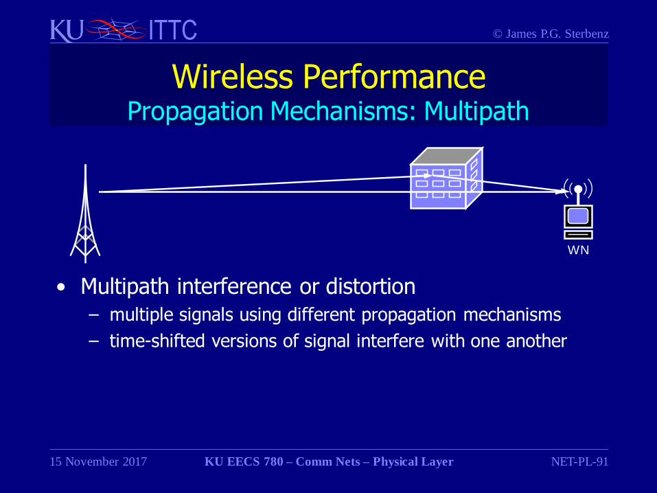
Wireless PerformancePropagation Mechanisms: Multipath
• Multipath interference or distortion
– multiple signals using different propagation mechanisms
– time-shifted versions of signal interfere with one another
WN
Page 92
© James P.G. SterbenzITTC
15 November 2017 KU EECS 780 – Comm Nets – Physical Layer NET-PL-92
Physical MediaPerformance Characteristics Summary
Type MediumFrequency
Range Velocity DelayTypical
Attenuation
Wiretwisted pair 0–1 MHz 0.67c 5 s/km 0.7 dB/km
coax 0–500 MHz 0.66–0.95c 4 s/km 7.0 dB/km
Optical fiber glass120–250 THz1700–800 nm
0.68c 5 s/km 0.2–0.5 dB/km
Wireless
microwave 1–300 GHz
1.0c 3.3 s/km 1/r 2infrared 0.3–428 THz
visible 428–750 THz
Page 93
© James P.G. SterbenzITTC
15 November 2017 KU EECS 780 – Comm Nets – Physical Layer NET-PL-93
Physical LayerFurther Reading
• William Stallings,Data and Computer Communications, 8th ed.
Pearson Prentice Hall, Upper Saddle River NJ, 2007.
Page 94
© James P.G. SterbenzITTC
15 November 2017 KU EECS 780 – Comm Nets – Physical Layer NET-PL-94
Physical LayerAcknowledgements
Some material in these foils comes from the textbook supplementary materials:
• Sterbenz & Touch,High-Speed Networking:
A Systematic Approach to
High-Bandwidth Low-Latency Communication
http://hsn-book.sterbenz.org