International Telecommunication Union ITU-T G.722.1 TELECOMMUNICATION STANDARDIZATION SECTOR OF ITU (05/2005) SERIES G: TRANSMISSION SYSTEMS AND MEDIA, DIGITAL SYSTEMS AND NETWORKS Digital terminal equipments – Coding of analogue signals by methods other than PCM Low-complexity coding at 24 and 32 kbit/s for hands-free operation in systems with low frame loss ITU-T Recommendation G.722.1
Transcript
I n t e r n a t i o n a l T e l e c o m m u n i c a t i o n U n i o n
ITU-T G.722.1TELECOMMUNICATION STANDARDIZATION SECTOR OF ITU
(05/2005)
SERIES G: TRANSMISSION SYSTEMS AND MEDIA, DIGITAL SYSTEMS AND NETWORKS Digital terminal equipments – Coding of analogue signals by methods other than PCM
Low-complexity coding at 24 and 32 kbit/s for hands-free operation in systems with low frame loss
ITU-T Recommendation G.722.1
ITU-T G-SERIES RECOMMENDATIONS TRANSMISSION SYSTEMS AND MEDIA, DIGITAL SYSTEMS AND NETWORKS
INTERNATIONAL TELEPHONE CONNECTIONS AND CIRCUITS G.100–G.199 GENERAL CHARACTERISTICS COMMON TO ALL ANALOGUE CARRIER-TRANSMISSION SYSTEMS
G.200–G.299
INDIVIDUAL CHARACTERISTICS OF INTERNATIONAL CARRIER TELEPHONE SYSTEMS ON METALLIC LINES
G.300–G.399
GENERAL CHARACTERISTICS OF INTERNATIONAL CARRIER TELEPHONE SYSTEMS ON RADIO-RELAY OR SATELLITE LINKS AND INTERCONNECTION WITH METALLIC LINES
G.400–G.449
COORDINATION OF RADIOTELEPHONY AND LINE TELEPHONY G.450–G.499 TRANSMISSION MEDIA CHARACTERISTICS G.600–G.699 DIGITAL TERMINAL EQUIPMENTS G.700–G.799
General G.700–G.709 Coding of analogue signals by pulse code modulation G.710–G.719 Coding of analogue signals by methods other than PCM G.720–G.729 Principal characteristics of primary multiplex equipment G.730–G.739 Principal characteristics of second order multiplex equipment G.740–G.749 Principal characteristics of higher order multiplex equipment G.750–G.759 Principal characteristics of transcoder and digital multiplication equipment G.760–G.769 Operations, administration and maintenance features of transmission equipment G.770–G.779 Principal characteristics of multiplexing equipment for the synchronous digital hierarchy G.780–G.789 Other terminal equipment G.790–G.799
DIGITAL NETWORKS G.800–G.899 DIGITAL SECTIONS AND DIGITAL LINE SYSTEM G.900–G.999 QUALITY OF SERVICE AND PERFORMANCE – GENERIC AND USER-RELATED ASPECTS
G.1000–G.1999
TRANSMISSION MEDIA CHARACTERISTICS G.6000–G.6999 DATA OVER TRANSPORT – GENERIC ASPECTS G.7000–G.7999 ETHERNET OVER TRANSPORT ASPECTS G.8000–G.8999 ACCESS NETWORKS G.9000–G.9999
For further details, please refer to the list of ITU-T Recommendations.
ITU-T Rec. G.722.1 (05/2005) i
ITU-T Recommendation G.722.1
Low complexity coding at 24 and 32 kbit/s for hands-free operation in systems with low frame loss
Summary This Recommendation describes a low complexity encoder and decoder that may be used for 7-kHz bandwidth audio signals working at 24 kbit/s or 32 kbit/s. Further, this algorithm is recommended for use in hands-free applications such as conferencing where there is a low probability of frame loss. It may be used with speech or music inputs. The bit rate may be changed at any 20-ms frame boundary. New Annex C contains the description of a low-complexity extension mode to G.722.1, which doubles the algorithm to permit 14-kHz audio bandwidth using a 32-kHz audio sample rate, at 24, 32, and 48 kbit/s. This mode is suitable for use in video conferencing, teleconferencing, and Internet streaming applications, and uses the same 20-ms frame length, 40-ms algorithmic delay, and same algorithmic steps as the 7-kHz mode. Less than 5.5 WMOPS are required for encoding and decoding in the baseline 7-kHz mode, and less than 11 WMOPS are required for encoding and decoding in the 14-kHz mode of Annex C.
This Recommendation includes a software package which contains the encoder and decoder source code and a set of test vectors for developers. These vectors are a tool providing an indication of success in implementing this code. The fixed-point code implements both the 7-kHz mode (main body) and the 14-kHz mode (Annex C). The floating point implements only the 7-kHz mode.
Source ITU-T Recommendation G.722.1 was approved on 14 May 2005 by ITU-T Study Group 16 (2005-2008) under the ITU-T Recommendation A.8 procedure.
ii ITU-T Rec. G.722.1 (05/2005)
FOREWORD
The International Telecommunication Union (ITU) is the United Nations specialized agency in the field of telecommunications. The ITU Telecommunication Standardization Sector (ITU-T) is a permanent organ of ITU. ITU-T is responsible for studying technical, operating and tariff questions and issuing Recommendations on them with a view to standardizing telecommunications on a worldwide basis.
The World Telecommunication Standardization Assembly (WTSA), which meets every four years, establishes the topics for study by the ITU-T study groups which, in turn, produce Recommendations on these topics.
The approval of ITU-T Recommendations is covered by the procedure laid down in WTSA Resolution 1.
In some areas of information technology which fall within ITU-T's purview, the necessary standards are prepared on a collaborative basis with ISO and IEC.
NOTE
In this Recommendation, the expression "Administration" is used for conciseness to indicate both a telecommunication administration and a recognized operating agency.
Compliance with this Recommendation is voluntary. However, the Recommendation may contain certain mandatory provisions (to ensure e.g. interoperability or applicability) and compliance with the Recommendation is achieved when all of these mandatory provisions are met. The words "shall" or some other obligatory language such as "must" and the negative equivalents are used to express requirements. The use of such words does not suggest that compliance with the Recommendation is required of any party.
INTELLECTUAL PROPERTY RIGHTS
ITU draws attention to the possibility that the practice or implementation of this Recommendation may involve the use of a claimed Intellectual Property Right. ITU takes no position concerning the evidence, validity or applicability of claimed Intellectual Property Rights, whether asserted by ITU members or others outside of the Recommendation development process.
As of the date of approval of this Recommendation, ITU had received notice of intellectual property, protected by patents, which may be required to implement this Recommendation. However, implementors are cautioned that this may not represent the latest information and are therefore strongly urged to consult the TSB patent database.
ITU 2005
All rights reserved. No part of this publication may be reproduced, by any means whatsoever, without the prior written permission of ITU.
5 C code ........................................................................................................................... 14
6 Flow chart of categorization procedure ........................................................................ 15
Annex A – Packet format, capability identifiers and capability parameters............................ 20 A.1 References ...................................................................................................... 20 A.2 Packet structure for G.722.1 frames ............................................................... 20 A.3 Capability Identifiers and Parameters for use with ITU-T Rec. H.245.......... 21
Annex B – Floating-point implementation for G.722.1........................................................... 23 B.1 Introduction .................................................................................................... 23 B.2 Algorithmic description.................................................................................. 23 B.3 ANSI C code................................................................................................... 24
Annex C – 14 kHz mode at 24, 32, and 48 kbit/s .................................................................... 25 C.1 Introduction .................................................................................................... 25 C.2 Algorithmic description.................................................................................. 25 C.3 ANSI C code................................................................................................... 27
ITU-T Rec. G.722.1 (05/2005) 1
ITU-T Recommendation G.722.1
Low-complexity coding at 24 and 32 kbit/s for hands-free operation in systems with low frame loss1
1 Scope This Recommendation describes a digital wideband coder algorithm that provides an audio bandwidth of 50 Hz to 7 kHz, operating at a bit rate of 24 kbit/s or 32 kbit/s. The digital input to the coder may be 14-, 15- or 16-bit 2's complement format at a sample rate of 16 kHz (handled in the same way as in ITU-T Rec. G.722). The analogue and digital interface circuitry at the encoder input and decoder output should conform to the same specifications described in ITU-T Rec. G.722.
The algorithm is based on transform technology, using a Modulated Lapped Transform (MLT). It operates on 20-ms frames (320 samples) of audio. Because the transform window (basis function length) is 640 samples and a 50 per cent (320 samples) overlap is used between frames, the effective look-ahead buffer size is 20 ms. Hence the total algorithmic delay of 40 ms is the sum of the frame size plus look-ahead. All other delays are due to computational and network transmission delays.
The description of the coding algorithm of this Recommendation is made in terms of bit-exact, fixed-point mathematical operations. The C code indicated in clause 5, which constitutes an integral part of this Recommendation, reflects this bit-exact, fixed-point descriptive approach, and shall take precedence over the mathematical descriptions of clauses 3 and 4 whenever discrepancies are found.
The mathematical descriptions of the encoder (clause 3), and decoder (clause 4), could have been implemented in several other fashions, but the C code of clause 5 has been provided as reference purposes. Thus, to comply with this Recommendation, any implementation must produce for any input signal the same output results as the C code of clause 5.
Note that to ensure that this goal is achieved, implementations should follow the computational details, tables of constants, sequencing of variable adaptation and use given by the C code of clause 5. However, it is recognized that there are many parts of the algorithm critical to maintaining correct bit-exact operation. For these parts, implementations shall reproduce the computational details, tables of constants, sequencing of variables adaptation and use written in the C code of clause 5.
It is recognized that the C code provided is for reference, and has not been optimized (in terms of memory, complexity, etc.) for a specific implementation platform. The C code may require optimization for a particular implementation.
A non-exhaustive set of test signals is provided as part of this Recommendation, as a tool to assist implementors to verify their implementations of the encoder and decoder comply with this Recommendation.
In practice, purchasers of wideband equipment or software implementations will expect them to be compliant with this standard to ensure interworking capability. Implementors may choose to optimize the C code, or otherwise modify the reference C code. In such cases the implementor shall verify that his implementation produces the same resultant output for any given input as would be expected using the C code expressed in clause 5.
____________________ 1 This Recommendation includes a software package that contains the encoder and decoder source code and
a set of test vectors for developers.
2 ITU-T Rec. G.722.1 (05/2005)
2 Normative references The following ITU-T Recommendations and other references contain provisions which, through reference in this text, constitute provisions of this Recommendation. At the time of publication, the editions indicated were valid. All Recommendations and other references are subject to revision; users of this Recommendation are therefore encouraged to investigate the possibility of applying the most recent edition of the Recommendations and other references listed below. A list of the currently valid ITU-T Recommendations is regularly published. The reference to a document within this Recommendation does not give it, as a stand-alone document, the status of a Recommendation.
[1] CCITT Recommendation G.722 (1988), 7-kHz audio-coding within 64 kbit/s.
[2] ITU-T Recommendation G.192 (1996), A common digital parallel interface for speech standardization activities.
[3] ISO/IEC 9899:1999, Programming languages – C.
3 The encoder Figure 1 presents a block diagram of the encoder.
Figure 1/G.722.1 – Block diagram of the encoder
Every 20 milliseconds (320 samples) the most recent 640 time domain audio samples are fed to a Modulated Lapped Transform (MLT). Each transform produces a frame of 320 MLT coefficients, and each frame of MLT coefficients is coded independently, i.e., there is no state information left
ITU-T Rec. G.722.1 (05/2005) 3
over from the previous frame. For 24-kbit/s and 32-kbit/s operation the allotment of bits per frame is 480 and 640, respectively.
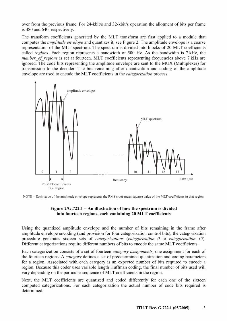
The transform coefficients generated by the MLT transform are first applied to a module that computes the amplitude envelope and quantizes it; see Figure 2. The amplitude envelope is a coarse representation of the MLT spectrum. The spectrum is divided into blocks of 20 MLT coefficients called regions. Each region represents a bandwidth of 500 Hz. As the bandwidth is 7 kHz, the number_of_regions is set at fourteen. MLT coefficients representing frequencies above 7 kHz are ignored. The code bits representing the amplitude envelope are sent to the MUX (Multiplexer) for transmission to the decoder. The bits remaining after quantization and coding of the amplitude envelope are used to encode the MLT coefficients in the categorization process.
Figure 2/G.722.1 – An illustration of how the spectrum is divided into fourteen regions, each containing 20 MLT coefficients
Using the quantized amplitude envelope and the number of bits remaining in the frame after amplitude envelope encoding (and provision for four categorization control bits), the categorization procedure generates sixteen sets of categorizations (categorization 0 to categorization 15). Different categorizations require different numbers of bits to encode the same MLT coefficients.
Each categorization consists of a set of fourteen category assignments, one assignment for each of the fourteen regions. A category defines a set of predetermined quantization and coding parameters for a region. Associated with each category is an expected number of bits required to encode a region. Because this coder uses variable length Huffman coding, the final number of bits used will vary depending on the particular sequence of MLT coefficients in the region.
Next, the MLT coefficients are quantized and coded differently for each one of the sixteen computed categorizations. For each categorization the actual number of code bits required is determined.
4 ITU-T Rec. G.722.1 (05/2005)
The quantization and encoding proceed region by region. A categorization determines the category assignment for all the fourteen regions, and the category assignment together with the amplitude envelope for each region determine all of the quantization and coding parameters that will be used for all twenty MLT coefficients in the region.
The MLT coefficients in a region are first normalized by the quantized amplitude envelope in the region and then scalar quantized. The resulting scalar quantization indices are combined into vector indices. The vector indices are then Huffman coded, i.e., they are coded with a variable number of bits. The most frequent vector indices require fewer bits than the less frequent vector indices.
Because this codec uses variable length Huffman coding and a constant transmitted bit rate is required, a method of constraining the bit rate to the channel rate is required. Four categorization control bits identify to the decoder which categorization was selected. The categorization switch directs the code bits (representing the quantized MLT coefficients produced using the selected categorization) to the MUX for transmission. The categorization that results in providing the number of bits closest to the channel rate is selected for transmission.
3.1 The Modulated Lapped Transform (MLT) The MLT is a critically sampled, perfect reconstruction, linear transform with a 50-percent overlap between the basis functions of adjacent MLT frames. The inputs to each MLT are the most recent 640 audio samples, x(n),
where:
x (0) is the oldest sample,
and: 0 ≤ n < 640
The MLT outputs 320 transform coefficients, mlt(m),
where: 0 ≤ m < 320 The MLT is given by:
)()5.0)(5.159(320
cos)5.0(640
sin320
2)(639
0nxmnnmmlt
n
+−π
+π= ∑
=
The MLT can be decomposed into a window, overlap and add operation followed by a type IV Discrete Cosine Transform (DCT). The window, overlap and add operation is given by:
for)160()160()159()159()( nxnwnxnwnv +++−−= 1590 ≤≤ n
for)639()()320()319()160( nxnwnxnwnv −−+−=+ 1590 ≤≤ n
where:
for)5.0(640
sin)(
+π= nnw 3200 <≤ n
Combining v n( ) with a type IV DCT, the resulting expression for the MLT is:
)()5.0)(5.0(320
cos320
2)(319
0nvmnmmlt
n
++π= ∑
=
Note that fast transform techniques are used to significantly reduce the complexity of the DCT.
ITU-T Rec. G.722.1 (05/2005) 5
3.2 Computing and quantizing the amplitude envelope The MLT coefficients are divided into regions of twenty coefficients. Thus, the total number_of_regions = 14. Region r includes MLT coefficients 20r through 20r + 19,
where:
0 ≤ r < number_of_regions
The forty highest frequency MLT coefficients, representing frequencies above 7 kHz, are not used because they are outside the bandwidth of interest.
The amplitude envelope in the region r is defined as the RMS (Root-Mean-Square) value of the MLT coefficients in the region, and is computed as
∑=
++=19
0)20()20(
201)(
nnrmltnrmltrrms
It is then quantized. The quantizer output index is rms_index(r). The allowed set of quantization reconstruction values are:
+
22
2i
for integer values of i, 318 ≤≤− i
and rms_index(0) is further constrained so that
31)0(_1 ≤≤ indexrms
A log domain metric is used so that the values which get quantized to
+
22
2i
range from
+−
225.0
2i
to
++
225.0
2i
.
For example, if rms(r) = 310, then the corresponding quantization level is
+
2215
2 or 362.04, and
rms_index(r) = 15, because
+−
225.015
2 = 304.43.
3.3 Coding the amplitude envelope rms_index(0) is the first value transmitted in each frame. Five bits are used. The most significant bit of the index is transmitted first. The value, rms_index(0) = 0, is reserved and not used.
The indices of the remaining thirteen regions are differentially coded and then Huffman coded for transmission. The largest differences which may be coded are +11 and −12. To contain the differences within this range, the valleys are first adjusted upwards to allow the peaks which follow them to be accurately represented. This is described in the following in pseudo C code:
for (r = number_of_regions – 2; r > = 0; r--) {
if (rms_index[r] < rms_index[r + 1] – 11) rms_index[r] = rms_index[r + 1] – 11; } for (r = 1; r < number_of_regions; r + +) { j = rms_index[r] – rms_index[r – 1]; if (j < – 12)
The differences, differential_rms_index[r], are transmitted in order of region. They are coded in accordance with the variable length Huffman codes defined in table differential_region_power_codes[r][j + 12], and the table differential_region_power_bits[r][j + 12] which defines the number of bits for each Huffman code. These arrays are contained in the C code part of this Recommendation. Each region is associated with a unique set of Huffman codes. The leftmost (or most significant) bit is always transmitted first.
3.4 Categorization procedure The categorization procedure determines the step-sizes (and other related quantization and coding parameters) used to quantize the MLT coefficients.
The process of categorization assigns a category to each of the regions. There are eight categories: 0-7. Sixteen different sets of categorizations are computed, and only one is selected for transmission.
The same categorization procedure is employed in the decoder. Hence, it is important for interoperability that when provided with the same inputs, different implementations of this procedure should produce identical categorizations. The inputs to this procedure are: • number_of_available_bits: the actual number of bits in the frame still unused after
accounting for the amplitude envelope and categorization control bits. • rms_index(): the set of quantized values of rms(r) for all regions.
The category assigned to a region determines the quantization and coding parameters for that region, and the expected total number of bits required to represent the region's quantized MLT coefficients. Because variable length Huffman coding is used, the actual number of bits will vary depending on the statistics of a region's MLT coefficients. Hence, of the sixteen possible categorization sets computed, according to criteria described later, the best fitting categorization will be selected for transmission.
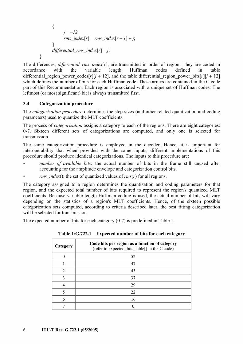
The expected number of bits for each category (0-7) is predefined in Table 1.
Table 1/G.722.1 – Expected number of bits for each category
Category Code bits per region as a function of category (refer to expected_bits_table[] in the C code)
0 52 1 47 2 43 3 37 4 29 5 22 6 16 7 0
ITU-T Rec. G.722.1 (05/2005) 7
3.4.1 Adjusting the number of available bits Based on the actual number of available bits, the following computes an estimation of the number of available bits:
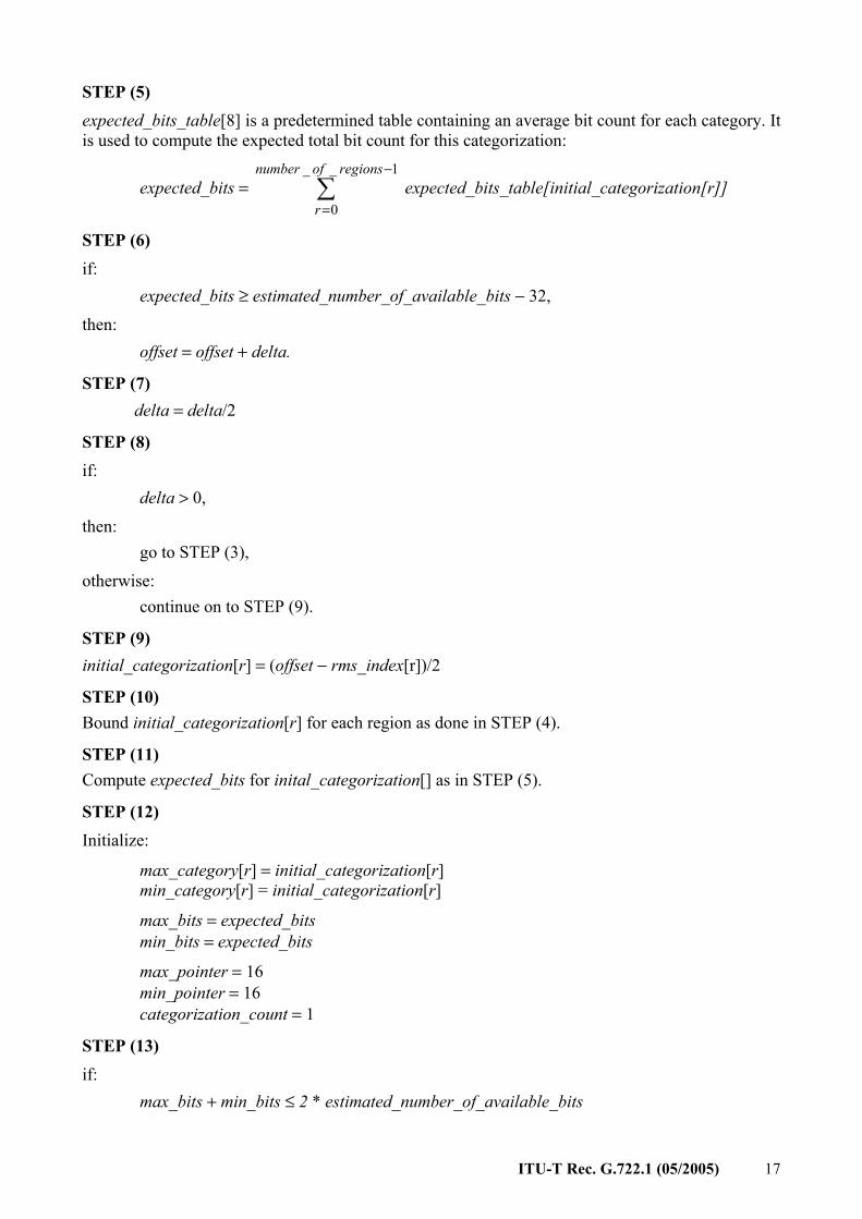
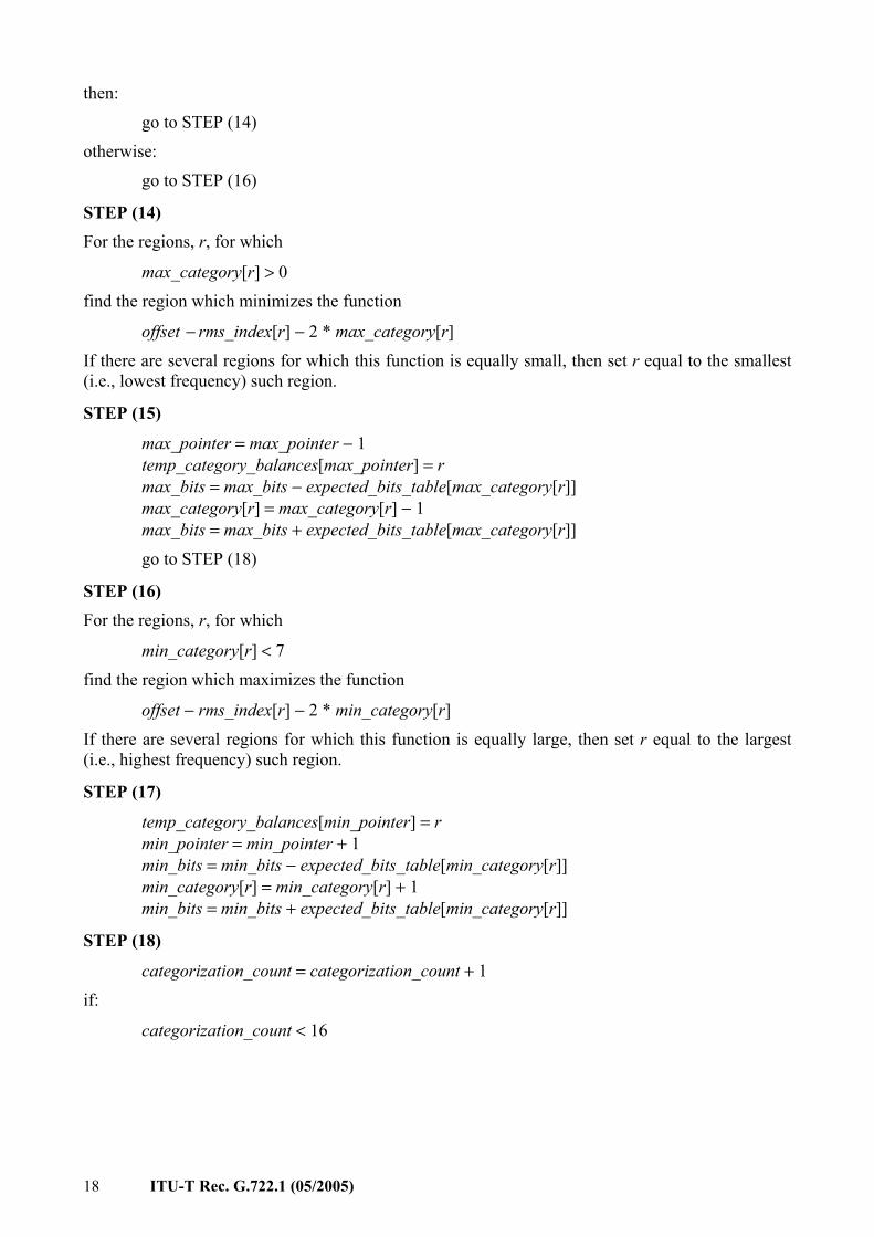
3.4.3 Generating the other fifteen categories Once the initial categorization has been computed, the fifteen other categorizations must then be calculated. For each new categorization the category is adjusted in only one region relative to the previous categorization. The method for determining the remaining categorizations now follows:
initial_categorization(r) = MAX {0, MIN {7, (offset − rms_index(r))/2}}
a new categorization is required with a larger expected number of bits.
For the regions, r, for which
max_category(r) > 0
find the region which minimizes the function
offset − rms_index(r) − 2 * max_category(r)
If there are several regions for which this function is equally small, then set r equal to the smallest (i.e., lowest frequency) such region.
The category for this region in max_category(r) is then decreased by one; the expected number of bits for this new categorization is re-computed and max_bits is set equal to it.
Otherwise:
a categorization with a smaller expected number of bits is required.
For the regions, r, for which
min_category(r) < 7
find the region which maximizes the function
offset − rms_index[r] − 2 * min_category(r)
If there are several regions for which this function is equally large, then set r equal to the largest (i.e., highest frequency) such region.
The category for this region in min_category(r) is then increased by one; the expected number of bits for this new categorization is re-computed and min_bits is set equal to it.
In this way, sixteen unique categorizations are produced. They are ordered according to their expected number of bits as detailed in clause 6. Categorization 0 has the largest expected number of bits and categorization 15 the smallest. Each categorization is the same as its neighbouring categorization, except in one region where the category entry will differ by one, e.g., region 5 of categorization 7 may have a category of 2, and in categorization 8 region 5 may have category 3, while being equal to categorization 7 in the other regions.
A detailed flow chart of the categorization procedure is provided in clause 6.
3.5 Scalar Quantized Vector Huffman Coding (SQVH)
For regions assigned category values 0-6, the MLT coefficients are separated into sign and magnitude parts. The magnitude parts are normalized by the quantized value of rms(r), then scalar quantized with dead zone expansion, combined into vectors, and Huffman coded. Regions that are assigned a category 7 are not processed in this way at all, and are not allocated any bits for transmission.
For each region, r, the encoder first normalizes and quantizes the absolute value of each MLT coefficient, mlt(i), to produce quantization index, k(i):
k(i) = MIN {whole number part of (x * absolute value of (mlt(20r + i)) + deadzone_rounding),kmax}
ITU-T Rec. G.722.1 (05/2005) 9
where the index within a particular region is:
0 ≤ i < 20
and:
x = 1/(stepsize * (quantized value of rms(r))
and:
stepsize, deadzone_rounding, and kmax are given in Table 2.
Table 2/G.722.1 – Table of constants used by the SQVH procedure
Category stepsize deadzone_rounding kmax
0 2−1.5 0.3 13
1 2−1.0 0.33 9
2 2−0.5 0.36 6
3 20.0 0.39 4
4 20.5 0.42 3
5 21.0 0.45 2
6 21.5 0.5 1
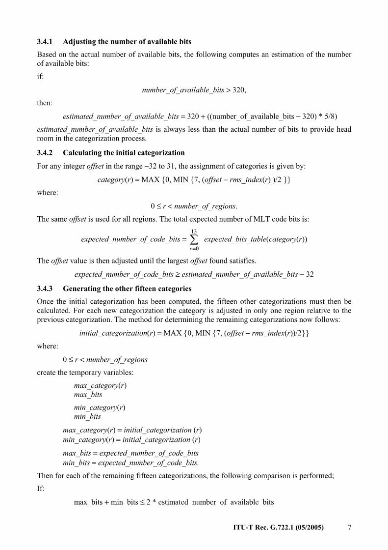
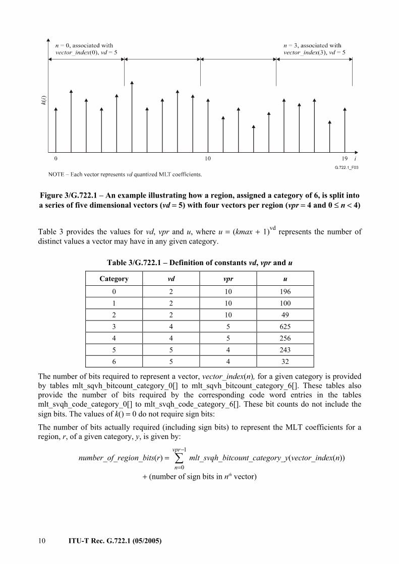
The indices, k(), are combined into vector indices; the properties of the vectors differ for each category. In each region there are vpr predefined vectors with dimension vd as defined in Table 3, and illustrated in Figure 3. The set of scalar k() values correspond to a unique vector identified by an index as follows:
vector_index(n) = ))1((1
0)1()( +−
−
=++×∑ jvd
vd
jkmaxjvdnk
where: 0 ≤ n ≤ vpr − 1, represents the nth vector in the region r
and: j = index to jth value of k() in a given vector, in a given region vd = vector dimension for given category vpr = number of vectors per region for a given category kmax = maximum value of k() for a given category as shown in Table 2.
10 ITU-T Rec. G.722.1 (05/2005)
Figure 3/G.722.1 – An example illustrating how a region, assigned a category of 6, is split into a series of five dimensional vectors (vd = 5) with four vectors per region (vpr = 4 and 0 ≤ n < 4)
Table 3 provides the values for vd, vpr and u, where u = (kmax + 1)vd represents the number of distinct values a vector may have in any given category.
Table 3/G.722.1 – Definition of constants vd, vpr and u
The number of bits required to represent a vector, vector_index(n), for a given category is provided by tables mlt_sqvh_bitcount_category_0[] to mlt_sqvh_bitcount_category_6[]. These tables also provide the number of bits required by the corresponding code word entries in the tables mlt_svqh_code_category_0[] to mlt_svqh_code_category_6[]. These bit counts do not include the sign bits. The values of k() = 0 do not require sign bits:
The number of bits actually required (including sign bits) to represent the MLT coefficients for a region, r, of a given category, y, is given by:
number_of_region_bits(r) = ∑−
=
1
0
vpr
nmlt_svqh_bitcount_category_y(vector_index(n))
+ (number of sign bits in nth vector)
ITU-T Rec. G.722.1 (05/2005) 11
3.6 Rate control The total number of bits actually required to represent the frame is computed for each categorization. This includes the bits used to represent the amplitude envelope, the four categorization control bits, and the bits required for the MLT coefficients. It then remains to select the best categorization for transmission and indicate this selection using the categorization control bits.
First, categorizations with bit totals in excess of the allotment are ruled out. Of the remaining categorizations the one with the lowest index is selected, e.g., when categorizations 0 through 3 use too many bits and categorization 4 fits within the bit allotment, categorization 4 is selected.
If no categorization yields a bit total that fits within the allotment, the categorization that comes closest (normally 15) is selected. Then, code bits are transmitted until the allotment for the frame is exhausted.
It may happen that the number of bits required by the encoder to represent one 20-ms frame of audio is less than the allowed number of bits per frame (480 or 640 bits). In this case the remaining unused bits at the end of the bit stream sequence are all set to one.
3.7 Transmission of the MLT vector indices
The vector indices are transmitted in frequency order – low to high frequency. They are coded in accordance with the variable length codes defined by the C code array mlt_svqh_bitcount_category_x[] and mlt_svqh_code_category_x[] (where _x represents the category value, 0 ≤ x ≤ 6). The leftmost (or most significant) bits are transmitted first. The sign bits, relating to the non-zero MLT coefficients of each vector, are transmitted immediately following the respective vector index variable length code. The sign bits are also transmitted in frequency order. The sign bit is set to "1" for positive numbers.
3.8 Bit stream The total number of bits in a frame is either 480 or 640 bits, for the bit rates of 24 kbit/s and 32 kbit/s respectively. While the number of bits in a frame is fixed, except for the categorization control bits parameter, all other parameters are represented by variable length codes − or a variable number of bits. Figure 4 illustrates this point, and the order of the transmitted parameter fields. All variable length codes, and the categorization control bits, are transmitted in order from the left most (most significant) bit to the right most (least significant) bit.
Figure 4/G.722.1 – Major bit stream fields and their order in transmission
4 The decoder First for every frame, the first five bits, representing the amplitude index for region zero, are decoded. Then, the remaining regions are Huffman decoded and reconstructed. The four categorization control bits can then be decoded to determine which of the sixteen possible categorizations was selected and transmitted by the encoder. The remaining code bits in the frame represent the quantized MLT coefficients and they are decoded according to the category information for each region. Just like in the encoder, the categorization procedure in the decoder
12 ITU-T Rec. G.722.1 (05/2005)
uses the amplitude envelope together with the number of bits remaining to be decoded (in the current frame) and computes the set of sixteen possible categorizations.
Some regions may have been assigned a category of 7 by the encoder. This means that no MLT coefficients were transmitted to represent these regions. The category 7 regions are reconstructed using a technique called noise-fill. The average MLT magnitude for these regions is available from the amplitude envelope. Instead of setting the category 7 MLT coefficients to zero, the decoder sets the value of their amplitude proportional to the average MLT coefficient magnitude for the region, and the sign of each coefficient is set randomly. Determining the coefficient signs may be done by one of a number of methods; a simple pseudo-random number generator is sufficient.
Noise-fill is also applied to categories 5 and 6, because for these categories many of the MLT coefficients may be quantized to zero. The values, which were transmitted as zero, are set to small fractions of the average magnitude for the region. Again, the signs are determined randomly.
For those coefficients that were scalar quantized to non-zero values, a predetermined table contains reconstruction values of the normalized coefficients. The reconstructed values are then scaled using the appropriate value of rms(r). The forty MLT coefficients representing frequencies above 7 kHz are set to zero. After reconstruction of the MLT coefficients, the Inverse Modulated Lapped Transform (IMLT) generates 320 new time domain samples.
Except for the final overlap and add operation of the IMLT, the information received in each frame by the decoder is independent of the information in the previous frame.
4.1 Decoding the amplitude envelope The first five bits of the frame represent rms_index(0). Then, for the remaining regions, the variable length codes for differential_rms_index(r) are decoded according to the arrays differential_region_power_bits[][] and differential_region_power_codes[][] referenced in the C code; the quantizer indices for these regions are reconstructed as follows:
4.2 Determining categorization After decoding the amplitude envelope, the decoder determines the number of bits remaining to represent the MLT coefficients, this is done as follows:
bits available = bits per frame – amplitude envelope bits – four (categorization control bits)
Using the same categorization procedure as the encoder, the same set of sixteen possible categorizations is computed. The four categorization control bits indicate which categorization was used to encode the MLT coefficients, and consequently should also be used by the decoder.
4.3 Decoding MLT coefficients For each region, the variable length codes representing the MLT vectors are decoded according to the appropriate category tables. The arrays mlt_svqh_bitcount_category_x[] and mlt_svqh_code_category_x[] are used for this purpose in the C code. (Where _x represents the category value, 0 ≤ x ≤ 6.) The individual MLT coefficient quantization indices, k(i), in a region are recovered from the vector index as follows:
)1()1(
)(_)( +
+= kmaxMOD
kmaxnindexvectorik j
ITU-T Rec. G.722.1 (05/2005) 13
where: z indicates taking the greatest integer value less than or equal to z
i = (n + 1)vd − j − 1 0 ≤ j ≤ vd − 1
0 ≤ n ≤ vpr−1, represents the nth vector in the region r,
and: vd = vector dimension for a given category kmax = maximum value of k() for a given category as shown in Table 2.
Reconstruction of the MLT coefficients uses the centroid tables in the C code array mlt_quant_centroid[][]. The MLT coefficient amplitudes are reconstructed by computing the product of rms(r), in the region of interest, and the centroid specified by the decoded vector index. Non-zero values have their signs set according to the sign bit.
4.4 Noise-fill
No MLT coefficient amplitudes are encoded for regions assigned category 7. For categories 5 and 6 the large quantizer step sizes result in most MLT coefficients being coded as zero; these zeroes are replaced with coefficient values of random sign and amplitude proportional to rms(r). The proportionality constants are defined in Table 4.
4.5 Insufficient bits There may be frames for which the encoder ran out of bits before it finished coding the last non-category 7 region. The decoder action in these cases is to process that region and all remaining regions with a category 7 assignment.
4.6 Frame erasure
If the decoder is informed (by means of an external signalling mechanism not defined in this Recommendation) that a frame has been lost or corrupted, it repeats the previous frame's decoded MLT coefficients. It proceeds by transforming them to the time domain, and performing the overlap and add operation with the previous and next frame's decoded information. If the previous frame was also lost or corrupted, then the decoder sets all the current frames MLT coefficients to zero.
4.7 The Inverse MLT (IMLT) Each IMLT operation operates on 320 coefficients to produce 320 time domain audio samples. The IMLT can be decomposed into a type IV DCT followed by a window, overlap and add operation.
14 ITU-T Rec. G.722.1 (05/2005)
The type IV DCT is:
3190for )()5.0)(5.0(320
cos320
2)(319
0≤≤
++π= ∑
=nmmltnmnu
m
The window, overlap and add operation uses half of the samples from the current frame's DCT output with half of those from the previous frame's DCT output:
y(n) = w(n)u(159 − n) + w(319 − n)u_old(n) for 0 ≤ n ≤ 159
y(n + 160) = w(160 + n)u(n) − w(159 − n)u_old(159 − n) for 0 ≤ n ≤ 159, where:
+π= )5.0(
640sin)( nnw for 0 ≤ n ≤ 319
The unused half of u( ) is stored as u_old( ) for use in the next frame:
u_old(n) = u(n + 160) for 0 ≤ n ≤ 159
5 C code The attached ANSI-compliant 16/32-bit fixed-point source C code, which is an integral part of this Recommendation, is divided into a number of files. The algorithmic description given by the C code shall take precedence over the texts contained in the main body of this Recommendation or Annex C. Those files are listed in Table 5. NOTE – See Annex B for details of the floating-point C source code.
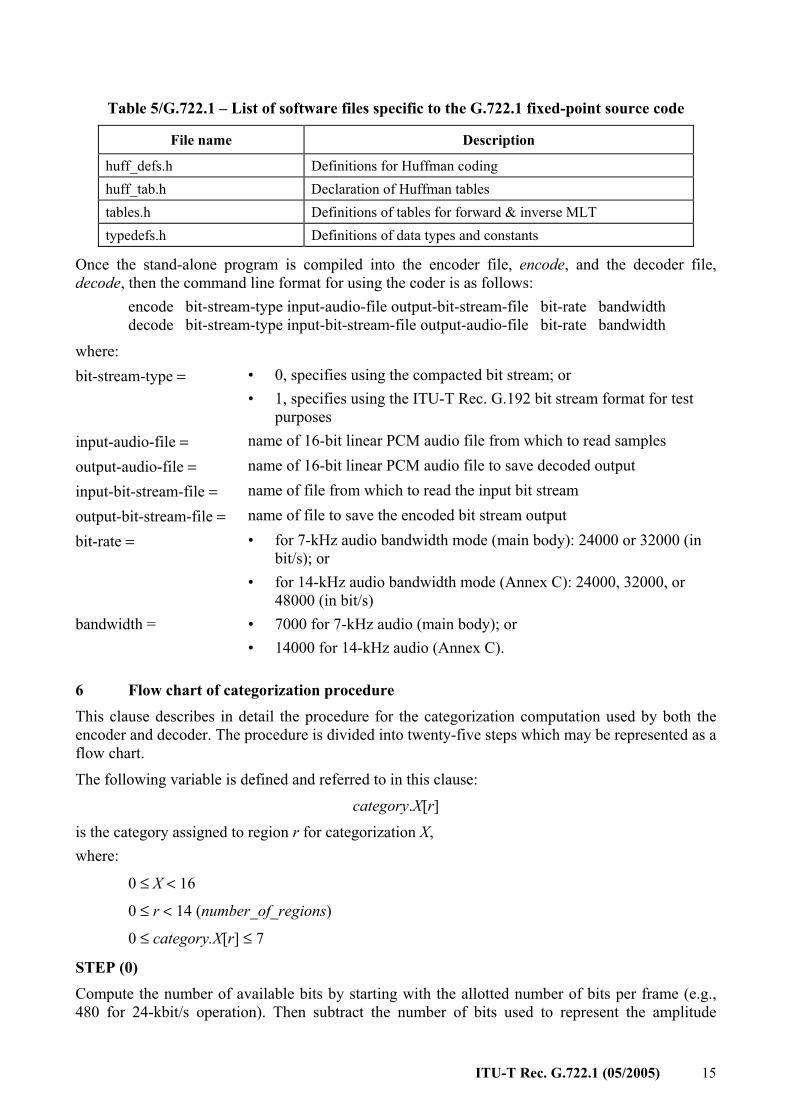
Table 5/G.722.1 – List of software files specific to the G.722.1 fixed-point source code
File name Description
basop32.c Basic arithmetic operators coef2sam.c Inverse MLT common.c Routines used by encoder and decoder count.c Functions for automatic complexity calculation dct4_a.c Forward DCT dct4_s.c Inverse DCT decode.c Main program for decoder decoder.c Routines for decoder encode.c Main program for encoder encoder.c Routines for encoder huff_tab.c Huffman coding for both encoder & decoder sam2coef.c Forward MLT tables.c Tables for forward & inverse MLT basop32.h Definitions of basic arithmetic operators count.h Definitions of functions for measuring complexity dct4_a.h Definitions of tables for forward DCT dct4_s.h Definitions of tables for inverse DCT defs.h Parameter definitions
ITU-T Rec. G.722.1 (05/2005) 15
Table 5/G.722.1 – List of software files specific to the G.722.1 fixed-point source code
File name Description
huff_defs.h Definitions for Huffman coding huff_tab.h Declaration of Huffman tables tables.h Definitions of tables for forward & inverse MLT typedefs.h Definitions of data types and constants
Once the stand-alone program is compiled into the encoder file, encode, and the decoder file, decode, then the command line format for using the coder is as follows:
where: bit-stream-type = • 0, specifies using the compacted bit stream; or
• 1, specifies using the ITU-T Rec. G.192 bit stream format for test purposes
input-audio-file = name of 16-bit linear PCM audio file from which to read samples output-audio-file = name of 16-bit linear PCM audio file to save decoded output input-bit-stream-file = name of file from which to read the input bit stream output-bit-stream-file = name of file to save the encoded bit stream output bit-rate = • for 7-kHz audio bandwidth mode (main body): 24000 or 32000 (in
bit/s); or • for 14-kHz audio bandwidth mode (Annex C): 24000, 32000, or
48000 (in bit/s) bandwidth = • 7000 for 7-kHz audio (main body); or
• 14000 for 14-kHz audio (Annex C).
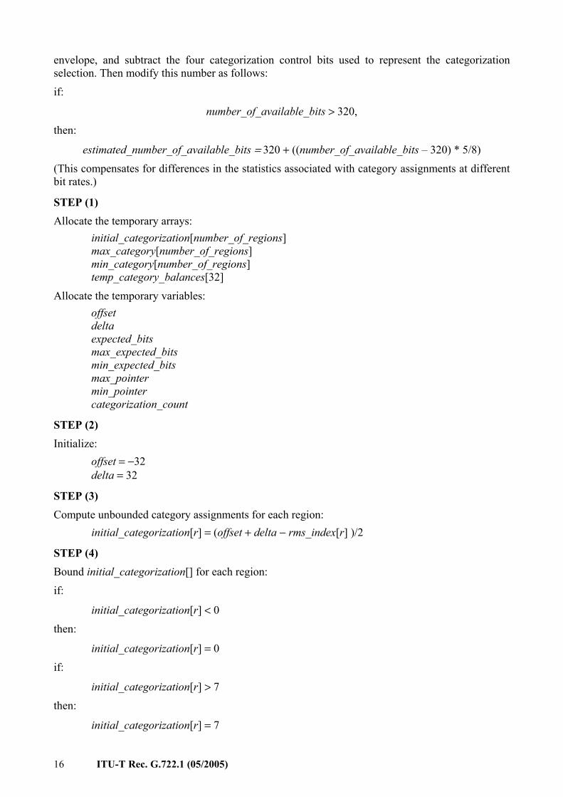
6 Flow chart of categorization procedure
This clause describes in detail the procedure for the categorization computation used by both the encoder and decoder. The procedure is divided into twenty-five steps which may be represented as a flow chart.
The following variable is defined and referred to in this clause:
category.X[r]
is the category assigned to region r for categorization X, where:
0 ≤ X < 16
0 ≤ r < 14 (number_of_regions)
0 ≤ category.X[r] ≤ 7
STEP (0) Compute the number of available bits by starting with the allotted number of bits per frame (e.g., 480 for 24-kbit/s operation). Then subtract the number of bits used to represent the amplitude
16 ITU-T Rec. G.722.1 (05/2005)
envelope, and subtract the four categorization control bits used to represent the categorization selection. Then modify this number as follows:
STEP (4) Bound initial_categorization[] for each region:
if:
initial_categorization[r] < 0
then:
initial_categorization[r] = 0
if:
initial_categorization[r] > 7
then:
initial_categorization[r] = 7
ITU-T Rec. G.722.1 (05/2005) 17
STEP (5) expected_bits_table[8] is a predetermined table containing an average bit count for each category. It is used to compute the expected total bit count for this categorization:
Packet format, capability identifiers and capability parameters
A.1 References [1] ITU-T Recommendation H.225.0 (2003), Call signalling protocols and media stream
packetization for packet-based multimedia communication systems.
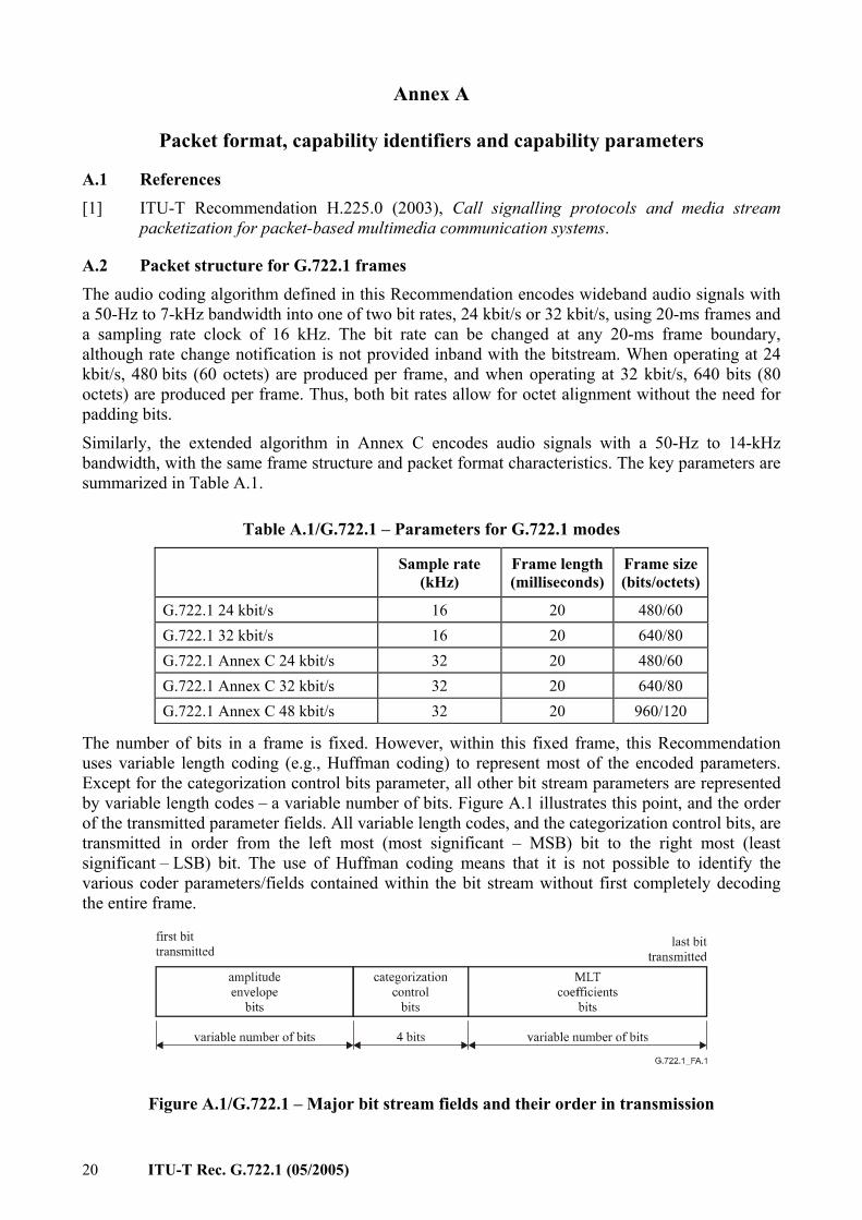
A.2 Packet structure for G.722.1 frames The audio coding algorithm defined in this Recommendation encodes wideband audio signals with a 50-Hz to 7-kHz bandwidth into one of two bit rates, 24 kbit/s or 32 kbit/s, using 20-ms frames and a sampling rate clock of 16 kHz. The bit rate can be changed at any 20-ms frame boundary, although rate change notification is not provided inband with the bitstream. When operating at 24 kbit/s, 480 bits (60 octets) are produced per frame, and when operating at 32 kbit/s, 640 bits (80 octets) are produced per frame. Thus, both bit rates allow for octet alignment without the need for padding bits.
Similarly, the extended algorithm in Annex C encodes audio signals with a 50-Hz to 14-kHz bandwidth, with the same frame structure and packet format characteristics. The key parameters are summarized in Table A.1.
The number of bits in a frame is fixed. However, within this fixed frame, this Recommendation uses variable length coding (e.g., Huffman coding) to represent most of the encoded parameters. Except for the categorization control bits parameter, all other bit stream parameters are represented by variable length codes – a variable number of bits. Figure A.1 illustrates this point, and the order of the transmitted parameter fields. All variable length codes, and the categorization control bits, are transmitted in order from the left most (most significant – MSB) bit to the right most (least significant – LSB) bit. The use of Huffman coding means that it is not possible to identify the various coder parameters/fields contained within the bit stream without first completely decoding the entire frame.
Figure A.1/G.722.1 – Major bit stream fields and their order in transmission
ITU-T Rec. G.722.1 (05/2005) 21
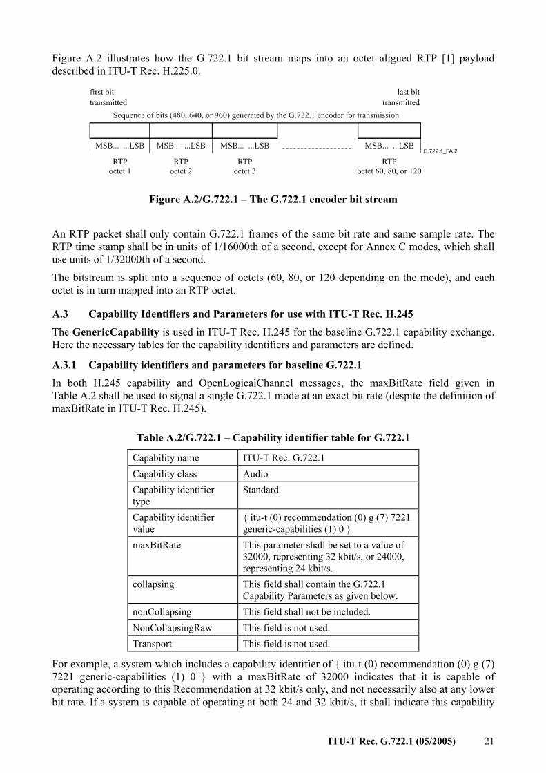
Figure A.2 illustrates how the G.722.1 bit stream maps into an octet aligned RTP [1] payload described in ITU-T Rec. H.225.0.
Figure A.2/G.722.1 – The G.722.1 encoder bit stream
An RTP packet shall only contain G.722.1 frames of the same bit rate and same sample rate. The RTP time stamp shall be in units of 1/16000th of a second, except for Annex C modes, which shall use units of 1/32000th of a second.
The bitstream is split into a sequence of octets (60, 80, or 120 depending on the mode), and each octet is in turn mapped into an RTP octet.
A.3 Capability Identifiers and Parameters for use with ITU-T Rec. H.245 The GenericCapability is used in ITU-T Rec. H.245 for the baseline G.722.1 capability exchange. Here the necessary tables for the capability identifiers and parameters are defined.
A.3.1 Capability identifiers and parameters for baseline G.722.1 In both H.245 capability and OpenLogicalChannel messages, the maxBitRate field given in Table A.2 shall be used to signal a single G.722.1 mode at an exact bit rate (despite the definition of maxBitRate in ITU-T Rec. H.245).
Table A.2/G.722.1 – Capability identifier table for G.722.1
Capability name ITU-T Rec. G.722.1 Capability class Audio Capability identifier type
maxBitRate This parameter shall be set to a value of 32000, representing 32 kbit/s, or 24000, representing 24 kbit/s.
collapsing This field shall contain the G.722.1 Capability Parameters as given below.
nonCollapsing This field shall not be included. NonCollapsingRaw This field is not used. Transport This field is not used.
For example, a system which includes a capability identifier of { itu-t (0) recommendation (0) g (7) 7221 generic-capabilities (1) 0 } with a maxBitRate of 32000 indicates that it is capable of operating according to this Recommendation at 32 kbit/s only, and not necessarily also at any lower bit rate. If a system is capable of operating at both 24 and 32 kbit/s, it shall indicate this capability
22 ITU-T Rec. G.722.1 (05/2005)
with two GenericCapability messages, one indicating a maxBitRate of 24000, and the other indicating a maxBitRate of 32000. NOTE – The units of the maxBitRate field in Table A.2, and the usage of this field, differ from the convention of ITU-T Rec. H.245 and from the units and usage in Table A.4. These units and usage have been established historically and are maintained for continued interoperability with deployed systems.
Table A.3 below defines the mandatory maxFramesPerPacket parameter. In a receive capability, this indicates the maximum number of encoded G.722.1 frames in a single RTP packet that the receiver is capable of decoding.
Table A.3/G.722.1 – Generic Capability parameter table for G.722.1, describing the maximum number of frames allowed in an RTP packet
Parameter name maxFramesPerPacket Parameter description This is a Collapsing GenericParameter. The value of
maxFramesPerPacket specifies the maximum number of encoded G.722.1 frames that may be included in a single RTP packet.
Parameter identifier value 1 Parameter status Mandatory Parameter type unsignedMin Supersedes This field is not used.
A.3.2 Capability identifiers and parameters for extended modes of G.722.1 Tables A.4 to A.6 specify the GenericCapability used in ITU-T Rec. H.245 for the extended modes of this Recommendation, including Annex C.
Table A.4/G.722.1 – Capability identifier table for extended modes of this Recommendation
Capability name ITU-T Rec. G.722.1 Extension Capability class Audio Capability identifier type Standard Capability identifier value { itu-t (0) recommendation (0) g (7) 7221 generic-capabilities (1)
extension (1) 0 } maxBitRate This parameter shall be set to a value of 480, representing 48 kbit/s,
320, representing 32 kbit/s, or 240, representing 24 kbit/s. collapsing This field shall contain the G.722.1 extended mode Capability
Parameters as given below. nonCollapsing This field shall not be included. NonCollapsingRaw This field is not used. Transport This field is not used.
The maxBitRate field of this capability identifier is used according to ITU-T Rec. H.245. It signals the maximum bit rate supported from the set of modes indicated in the supportedExtendedModes parameter below. A single { itu-t (0) recommendation (0) g (7) 7221 generic-capabilities (1) extension (1) 0 } capability identifier shall be used to signal all extended G.722.1 modes supported.
ITU-T Rec. G.722.1 (05/2005) 23
Table A.5/G.722.1 – Generic Capability parameter table for extended modes of G.722.1, describing the maximum number of frames allowed in an RTP packet
Parameter name maxFramesPerPacket Parameter description This is a Collapsing GenericParameter. The value of
maxFramesPerPacket specifies the maximum number of encoded extended mode G.722.1 frames that may be included in a single RTP packet.
Parameter identifier value 1 Parameter status Mandatory Parameter type unsignedMin Supersedes This field is not used.
Table A.6/G.722.1 – Generic Capability parameter table for extended modes of G.722.1, describing the supported modes
Parameter name supportedExtendedModes Parameter description This parameter is a Boolean array.
If bit 2 (value 64) is 1, this indicates Annex C at 24 kbit/s. If bit 3 (value 32) is 1, this indicates Annex C at 32 kbit/s. If bit 4 (value 16) is 1, this indicates Annex C at 48 kbit/s. All other bits are reserved, shall be set to 0, and shall be ignored by receivers. In a capability, for each bit set to 1, this means that the system is capable of operating according to the indicated mode(s). In an OpenLogicalChannel message, exactly one bit shall be set to 1, indicating the mode to be used on the logical channel. NOTE – If in the future more modes are defined than the number of reserved bits can accommodate, additional modes could be signalled by allocating another parameter for additional modes.
Parameter identifier value 2 Parameter status Mandatory Parameter type booleanArray Supersedes This field is not used.
Annex B
Floating-point implementation for G.722.1
B.1 Introduction This annex provides a description of the floating-point arithmetic implementation for the 7-kHz mode specified in the main body of this Recommendation.
B.2 Algorithmic description This floating-point version of the main body of this Recommendation has the same basic algorithmic steps as the fixed-point version for the 7-kHz mode.
24 ITU-T Rec. G.722.1 (05/2005)
B.3 ANSI C code ANSI-compliant C code simulating the floating-point version of the main body of this Recommendation is available as an attachment to this annex. The algorithmic description given by the C code shall take precedence over the texts contained in the main body of this Recommendation or this annex.
The files in Table B.1 comprise the floating-point source C code.
Table B.1/G.722.1 – List of software files specific to G.722.1 floating-point source code
File name Description
common.c routines used by encoder and decoder dct4.c forward and inverse DCT decode.c main program for decoder decoder.c routines for decoder encode.c main program for encoder encoder.c routines for encoder rmlt_coefs_to_samples.c inverse MLT samples_to_rmlt_coefs.c MLT defs.h parameter definitions huff_defs.h definitions for Huffman coding huff_tables.h declaration of Huffman tables
Once the stand-alone (floating-point) program is compiled into the encoder file, encode, and the decoder file, decode, then the command line format for using the coder is as follows: encode bit-stream-type input-audio-file output-bit-stream-file bit-rate decode bit-stream-type input-bit-stream-file output-audio-file bit-rate
where: bit-stream-type = • 0, specifies using the compacted bit stream; or
• 1, specifies using the ITU-T Rec. G.192 bit stream format for test purposes
input-audio-file name of 16-bit PCM audio file from which to read samples; output-audio-file name of 16-bit PCM audio file to save decoded output; input-bit-stream-file name of file from which to read the input bit stream; output-bit-stream-file name of file to save the encoded bit stream output; bit-rate = 24000 or 32000 for 24-kbit/s and 32-kbit/s operation respectively.
ITU-T Rec. G.722.1 (05/2005) 25
Annex C
14 kHz mode at 24, 32, and 48 kbit/s
C.1 Introduction This annex provides a description of the 14-kHz mode at 24, 32, and 48 kbit/s for this Recommendation.
C.2 Algorithmic description The 14 kHz mode of this Recommendation has the same algorithmic steps as the main G.722.1 (7-kHz audio bandwidth) mode, except that the algorithm is doubled to accommodate the doubled audio bandwidth.
The specific differences in the algorithm for this annex compared to that for the main body of this Recommendation are as follows: a) Double sample rate from 16 to 32 kHz. b) Double samples per frame from 320 to 640 samples (same 20-ms frame length). c) Double transform window from 640 to 1280 samples as follows:
The inputs to each MLT are the most recent 1280 audio samples, x(n),
where:
x (0) is the oldest sample, and:
0 ≤ n < 1280
The MLT outputs 640 transform coefficients, mlt(m), where:
0 ≤ m < 640 The MLT is given by:
)()5.0)(5.319(640
cos)5.0(1280
sin640
2)(1279
0nxmnnmmlt
n
+−π
+π= ∑
=
The MLT can be decomposed into a window, overlap and add operation followed by a type IV Discrete Cosine Transform (DCT). The window, overlap and add operation is given by:
for)320()320()319()319()( nxnwnxnwnv +++−−= 3190 ≤≤ n
for)1279()()640()639()320( nxnwnxnwnv −−+−=+ 3190 ≤≤ n
where:
for)5.0(1280
sin)(
+π= nnw 6400 <≤ n
Combining v n( ) with a type IV DCT, the resulting expression for the MLT is:
)()5.0)(5.0(640
cos640
2)(639
0nvmnmmlt
n
++π= ∑
= for 0 ≤ m < 640
Each IMLT operation operates on 640 coefficients to produce 640 time domain audio samples. The IMLT can be decomposed into a type IV DCT followed by a window, overlap and add operation.
26 ITU-T Rec. G.722.1 (05/2005)
The type IV DCT is:
639 0for)()5.0)(5.0(640
cos640
2)(639
0≤≤
++π= ∑
=nmmltnmnu
m
The window, overlap and add operation uses half of the samples from the current frame's DCT output with half of those from the previous frame's DCT output:
y(n) = w(n)u(319 − n) + w(639 − n)u_old(n) for 0 ≤ n ≤ 319
y(n + 320) = w(320 + n)u(n) − w(319 − n)u_old(319 − n) for 0 ≤ n ≤ 319,
where:
+= )5.0(1280
sin)( nnw π for 0 ≤ n ≤ 639
The unused half of u( ) is stored as u_old( ) for use in the next frame:
u_old(n) = u(n + 320) for 0 ≤ n ≤ 319 d) Add new DCT tables to accommodate double bandwidth as follows: A new table a_cos_msin_64[320][2] is added in dct4_a.h for the forward DCT and two
new tables s_cos_msin_64[320][2] and max_dither[640] are added in dct4_s.h for the inverse DCT, respectively (see dct4_a.h and dct4_s.h for details).
e) Double number of 500-Hz sub-bands from 14 to 28. f) Double Huffman coding tables as follows: The following Huffman coding tables become larger compared to those used for the main
body of this Recommendation. differential_region_power_bits[28][24] differential_region_power_codes[28][24] differential_region_power_decoder_tree[28][23][2] mlt_quant_centroid[8][16] The first three tables mentioned above are obtained by repeating the last row of the
corresponding tables of this Recommendation and the fourth is obtained by adding a new row and two columns of zeros to the table of this Recommendation (see huff_tab.c for details).
g) The total number of bits in a frame is 480, 640, or 960 bits, for the bit rates of 24, 32, and 48 kbit/s, respectively. This includes the bits used to represent the amplitude envelope, the four categorization control bits, and the bits required for the MLT coefficients. The bit allocation is dynamically performed over full frequency band of 14-kHz frame by frame.
h) Double threshold for adjusting the number of available bits as follows: Based on the actual number of available bits, the following computes an estimation of the
estimated_number_of_available_bits is always less than the actual number of bits to provide head room in the categorization process.
ITU-T Rec. G.722.1 (05/2005) 27
C.3 ANSI C code The ANSI-compliant C code simulating the 14-kHz mode specified in this annex has been integrated with the C source of the 7-kHz mode specified in the main body of this Recommendation. The files and usage are common to both modes and are detailed in clause 5.
Printed in Switzerland Geneva, 2005
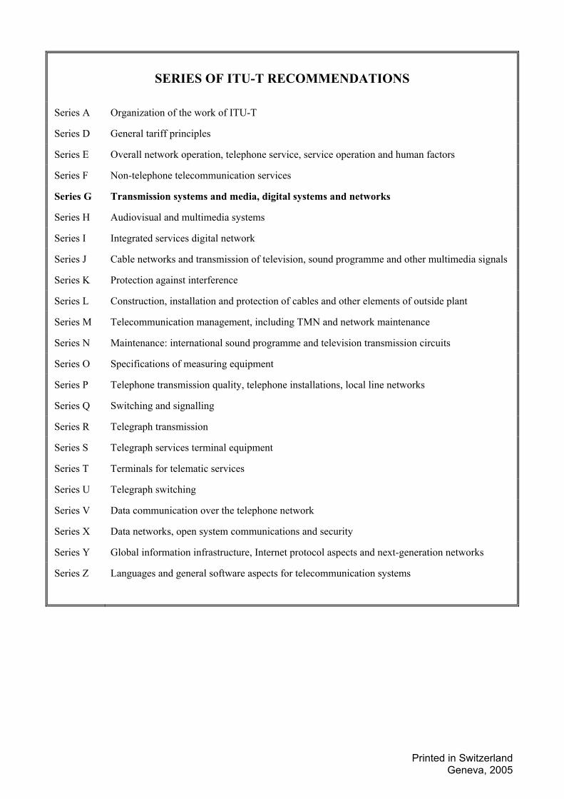
SERIES OF ITU-T RECOMMENDATIONS
Series A Organization of the work of ITU-T
Series D General tariff principles
Series E Overall network operation, telephone service, service operation and human factors
Series F Non-telephone telecommunication services
Series G Transmission systems and media, digital systems and networks
Series H Audiovisual and multimedia systems
Series I Integrated services digital network
Series J Cable networks and transmission of television, sound programme and other multimedia signals
Series K Protection against interference
Series L Construction, installation and protection of cables and other elements of outside plant
Series M Telecommunication management, including TMN and network maintenance
Series N Maintenance: international sound programme and television transmission circuits
Series O Specifications of measuring equipment
Series P Telephone transmission quality, telephone installations, local line networks
Series Q Switching and signalling
Series R Telegraph transmission
Series S Telegraph services terminal equipment
Series T Terminals for telematic services
Series U Telegraph switching
Series V Data communication over the telephone network
Series X Data networks, open system communications and security
Series Y Global information infrastructure, Internet protocol aspects and next-generation networks
Series Z Languages and general software aspects for telecommunication systems