International Telecommunication Union ITU-T G.993.2 TELECOMMUNICATION STANDARDIZATION SECTOR OF ITU (02/2006) SERIES G: TRANSMISSION SYSTEMS AND MEDIA, DIGITAL SYSTEMS AND NETWORKS Digital sections and digital line system – Access networks Very high speed digital subscriber line transceivers 2 (VDSL2) ITU-T Recommendation G.993.2
Transcript
I n t e r n a t i o n a l T e l e c o m m u n i c a t i o n U n i o n
ITU-T G.993.2TELECOMMUNICATION STANDARDIZATION SECTOR OF ITU
(02/2006)
SERIES G: TRANSMISSION SYSTEMS AND MEDIA, DIGITAL SYSTEMS AND NETWORKS Digital sections and digital line system – Access networks
Very high speed digital subscriber line transceivers 2 (VDSL2)
ITU-T Recommendation G.993.2
ITU-T G-SERIES RECOMMENDATIONS TRANSMISSION SYSTEMS AND MEDIA, DIGITAL SYSTEMS AND NETWORKS
INTERNATIONAL TELEPHONE CONNECTIONS AND CIRCUITS G.100–G.199 GENERAL CHARACTERISTICS COMMON TO ALL ANALOGUE CARRIER-TRANSMISSION SYSTEMS
G.200–G.299
INDIVIDUAL CHARACTERISTICS OF INTERNATIONAL CARRIER TELEPHONE SYSTEMS ON METALLIC LINES
G.300–G.399
GENERAL CHARACTERISTICS OF INTERNATIONAL CARRIER TELEPHONE SYSTEMS ON RADIO-RELAY OR SATELLITE LINKS AND INTERCONNECTION WITH METALLIC LINES
G.400–G.449
COORDINATION OF RADIOTELEPHONY AND LINE TELEPHONY G.450–G.499 TRANSMISSION MEDIA CHARACTERISTICS G.600–G.699 DIGITAL TERMINAL EQUIPMENTS G.700–G.799 DIGITAL NETWORKS G.800–G.899 DIGITAL SECTIONS AND DIGITAL LINE SYSTEM G.900–G.999
General G.900–G.909 Parameters for optical fibre cable systems G.910–G.919 Digital sections at hierarchical bit rates based on a bit rate of 2048 kbit/s G.920–G.929 Digital line transmission systems on cable at non-hierarchical bit rates G.930–G.939 Digital line systems provided by FDM transmission bearers G.940–G.949 Digital line systems G.950–G.959 Digital section and digital transmission systems for customer access to ISDN G.960–G.969 Optical fibre submarine cable systems G.970–G.979 Optical line systems for local and access networks G.980–G.989 Access networks G.990–G.999
QUALITY OF SERVICE AND PERFORMANCE – GENERIC AND USER-RELATED ASPECTS
G.1000–G.1999
TRANSMISSION MEDIA CHARACTERISTICS G.6000–G.6999 DATA OVER TRANSPORT – GENERIC ASPECTS G.7000–G.7999 ETHERNET OVER TRANSPORT ASPECTS G.8000–G.8999 ACCESS NETWORKS G.9000–G.9999
For further details, please refer to the list of ITU-T Recommendations.
ITU-T Rec. G.993.2 (02/2006) i
ITU-T Recommendation G.993.2
Very high speed digital subscriber line transceivers 2 (VDSL2)
Summary This Recommendation is an access technology that exploits the existing infrastructure of copper wires that were originally deployed for POTS services. It can be deployed from central offices, from fibre-fed cabinets located near the customer premises, or within buildings. This Recommendation is an enhancement to ITU-T Rec. G.993.1 [1] that supports asymmetric and symmetric transmission at a bidirectional net data rate up to 200 Mbit/s on twisted pairs using a bandwidth up to 30 MHz.
Source ITU-T Recommendation G.993.2 was approved on 17 February 2006 by ITU-T Study Group 15 (2005-2008) under the ITU-T Recommendation A.8 procedure.
ii ITU-T Rec. G.993.2 (02/2006)
FOREWORD
The International Telecommunication Union (ITU) is the United Nations specialized agency in the field of telecommunications. The ITU Telecommunication Standardization Sector (ITU-T) is a permanent organ of ITU. ITU-T is responsible for studying technical, operating and tariff questions and issuing Recommendations on them with a view to standardizing telecommunications on a worldwide basis.
The World Telecommunication Standardization Assembly (WTSA), which meets every four years, establishes the topics for study by the ITU-T study groups which, in turn, produce Recommendations on these topics.
The approval of ITU-T Recommendations is covered by the procedure laid down in WTSA Resolution 1.
In some areas of information technology which fall within ITU-T's purview, the necessary standards are prepared on a collaborative basis with ISO and IEC.
NOTE
In this Recommendation, the expression "Administration" is used for conciseness to indicate both a telecommunication administration and a recognized operating agency.
Compliance with this Recommendation is voluntary. However, the Recommendation may contain certain mandatory provisions (to ensure e.g. interoperability or applicability) and compliance with the Recommendation is achieved when all of these mandatory provisions are met. The words "shall" or some other obligatory language such as "must" and the negative equivalents are used to express requirements. The use of such words does not suggest that compliance with the Recommendation is required of any party.
INTELLECTUAL PROPERTY RIGHTS
ITU draws attention to the possibility that the practice or implementation of this Recommendation may involve the use of a claimed Intellectual Property Right. ITU takes no position concerning the evidence, validity or applicability of claimed Intellectual Property Rights, whether asserted by ITU members or others outside of the Recommendation development process.
As of the date of approval of this Recommendation, ITU had received notice of intellectual property, protected by patents, which may be required to implement this Recommendation. However, implementors are cautioned that this may not represent the latest information and are therefore strongly urged to consult the TSB patent database.
7 Transmission medium interface characteristics............................................................ 25 7.1 Duplexing method and band plan construction .............................................. 25 7.2 Power spectral density (PSD)......................................................................... 26 7.3 Termination impedance .................................................................................. 39 7.4 Longitudinal conversion loss.......................................................................... 39
8 Transport protocol specific transmission convergence (TPS-TC) function ................. 40 8.1 The user data TPS-TC .................................................................................... 40 8.2 Management TPS-TC (MPS-TC)................................................................... 42 8.3 Network timing reference TPS-TC (NTR-TC) .............................................. 46
9 Physical media specific transmission convergence (PMS-TC) sub-layer .................... 47 9.1 PMS-TC functional model ............................................................................. 47 9.2 Scrambler........................................................................................................ 50 9.3 Forward error correction................................................................................. 50 9.4 Interleaving..................................................................................................... 51 9.5 Framing........................................................................................................... 52 9.6 Impulse noise protection (INPp) ..................................................................... 60 9.7 Delay............................................................................................................... 61 9.8 Bit error ratio (BER)....................................................................................... 61
10 Physical media dependent (PMD) function.................................................................. 61 10.1 PMD functional model ................................................................................... 62 10.2 DMT superframe ............................................................................................ 63 10.3 Symbol encoder for data symbols .................................................................. 63 10.4 Modulation ..................................................................................................... 78 10.5 Symbol encoder for sync symbol ................................................................... 82
iv ITU-T Rec. G.993.2 (02/2006)
Page 10.6 Symbol encoder for initialization ................................................................... 83
12 Link activation methods and procedures ...................................................................... 117 12.1 Overview ........................................................................................................ 117 12.2 Special operations channel (SOC).................................................................. 119 12.3 Initialization procedure................................................................................... 123 12.4 Loop diagnostic mode procedures.................................................................. 190 12.5 Fast startup...................................................................................................... 200
13 On-line reconfiguration (OLR)..................................................................................... 200 13.1 Types of on-line reconfiguration .................................................................... 200 13.2 Control parameters ......................................................................................... 201 13.3 Timing of changes in sub-carrier configuration ............................................. 201 13.4 Receiver initiated procedure........................................................................... 201
14 Electrical requirements ................................................................................................. 201 14.1 Termination impedance model ....................................................................... 201 14.2 Service splitters .............................................................................................. 201
Annex A – Region A (North America).................................................................................... 202 A.1 Band plan........................................................................................................ 202 A.2 PSD specifications.......................................................................................... 202
Annex B – Region B (Europe)................................................................................................. 207 B.1 Band plans ...................................................................................................... 207 B.2 Limit PSD mask options................................................................................. 207 B.3 Transmit PSD mask options ........................................................................... 215 B.4 Template PSD................................................................................................. 215 B.5 Compliance..................................................................................................... 215
Annex C – Region C (Japan) ................................................................................................... 216 C.1 Band plan........................................................................................................ 216 C.2 PSD masks...................................................................................................... 216 C.3 Service Splitter ............................................................................................... 219 C.4 Test loops and crosstalk disturbers................................................................. 219
Annex D .................................................................................................................................. 220
Annex E .................................................................................................................................. 220
Annex F .................................................................................................................................. 220
Annex G .................................................................................................................................. 220
ITU-T Rec. G.993.2 (02/2006) v
Page Annex H .................................................................................................................................. 221
Annex I .................................................................................................................................. 221
Very high speed digital subscriber line transceivers 2 (VDSL2)
1 Scope This Recommendation is an enhancement to ITU-T Rec. G.993.1 [1] that supports transmission at a bidirectional net data rate (the sum of upstream and downstream rates) up to 200 Mbit/s on twisted pairs. This Recommendation is an access technology that exploits the existing infrastructure of copper wires that were originally deployed for POTS (plain old telephone service).
This Recommendation specifies only discrete multi-tone (DMT) modulation and incorporates components from ITU-T Rec. G.993.1 (VDSL) [1], ITU-T Rec. G.992.3 (ADSL2) [10], and ITU-T Rec. G.992.5 (ADSL2 plus) [11].
Whilst POTS uses approximately the lowest 4 kHz and ADSL uses approximately 2 MHz of the copper wire spectrum, this Recommendation is defined to allow the use of up to 30 MHz of the spectrum. This Recommendation can be deployed from central offices, from fibre-fed cabinets located near the customer premises, or within buildings.
The availability of bandwidth up to 30 MHz allows G.993.2 transceivers to provide reliable high data rate operation on short loops. Without the use of the US0 band, this Recommendation should operate reliably over loop lengths that are similar to those of ITU-T Rec. G.993.1 [1], or slightly longer lengths due to the mandatory support of trellis coding. The addition of the US0 band and means to train echo cancellers and time-domain equalizers (TEQs) also allows this Recommendation to provide reliable operation on loops up to approximately 2500 metres of 26 AWG (0.4 mm).
This Recommendation defines a wide range of settings for various parameters (such as bandwidth and transmitter power) that could potentially be supported by a transceiver. Therefore, this Recommendation specifies profiles to allow transceivers to support a subset of the allowed settings and still be compliant with the Recommendation. The specification of multiple profiles allows vendors to limit implementation complexity and develop implementations that target specific service requirements. Some profiles are better suited for asymmetric data rate services, whereas other profiles are better for symmetric data rate services.
The annexes of this Recommendation include band plans and power spectral density (PSD) masks that address region-specific requirements.
Like ITU-T Rec. G.993.1 [1], this Recommendation defines upstream power back-off (UPBO) to mitigate far-end crosstalk (FEXT) caused by upstream transmissions on shorter loops to longer loops. The mechanism is the same as in ITU-T Rec. G.993.1 [1].
As do other ITU-T Recommendations in the G.99x series, this Recommendation uses ITU-T Rec. G.994.1 [2] to initiate the transceiver training sequence.
Changes in this Recommendation relative to ITU-T Rec. G.993.1 [1] include: • The definition, in annexes, of band plans up to 30 MHz to support a bidirectional net data
rate up to 200 Mbit/s; • Support for extension of the upper band edge of the US0 band to as high as 276 kHz (based
on Annex M/G.992.3 [10]); • The definition of means to improve the performance of US0 (specifically, support in
initialization for training of time domain equalizers and echo cancellers); • A requirement for downstream and upstream transmitters to notch, simultaneously,
16 arbitrary operator-defined RFI bands;
2 ITU-T Rec. G.993.2 (02/2006)
• The definition of profiles to support a wide range of deployment scenarios (e.g., central offices, fibre-fed cabinets located near the customer premises, and within buildings);
• A requirement to support the US0 band in the upstream direction for some profiles; • Support for downstream maximum transmit power (profile dependent) of up to 20.5 dBm; • Support for a MIB-controlled PSD mask mechanism to enable in-band spectrum shaping
(based on ITU-T Rec. G.992.5 [11]); • Mandatory support of trellis coding (based on ITU-T Rec. G.992.3 [10]); • The definition of receiver-determined tone ordering (based on ITU-T Rec. G.992.3 [10]); • Mandatory support of all integer-bit constellations from 1 bit to 15 bits; • Support for optional cyclic extension (CE) lengths as large as ¼ of a symbol period; • The definition of VTU-R receiver-selected pilot tone(s), including the option not to select a
pilot tone; • Support of all integer values of impulse noise protection (INP) up to 16 symbols; • Insertion of a sync symbol after every 256 data symbols to signal on-line reconfiguration
(OLR) transitions; • Improved OLR mechanisms (based on ITU-T Rec. G.992.3 [10]); • Improved framing (based on ITU-T Rec. G.992.3 [10]); • Improved overhead channel; • Improved interleaving; • Improved FEC capabilities, including a wider range of settings for the Reed-Solomon
encoder and the interleaver; • The definition of two latency paths and two bearer channels; • Improvements to initialization, including the definition of a channel discovery phase, a
training phase, and a channel analysis & exchange phase; • Support for a VTU-R lineprobe stage during initialization; • Support for a wide range of test parameters (based on ITU-T Rec. G.992.3 [10]); • The definition of a loop diagnostic mode; • Support for STM interfaces; • Support for PTM interfaces based on IEEE 802.3ah 64/65 octet encapsulation; and • Support for an optional all-digital mode.
2 References The following ITU-T Recommendations and other references contain provisions which, through reference in this text, constitute provisions of this Recommendation. At the time of publication, the editions indicated were valid. All Recommendations and other references are subject to revision; users of this Recommendation are therefore encouraged to investigate the possibility of applying the most recent edition of the Recommendations and other references listed below. A list of the currently valid ITU-T Recommendations is regularly published. The reference to a document within this Recommendation does not give it, as a stand-alone document, the status of a Recommendation.
[1] ITU-T Recommendation G.993.1 (2004), Very high speed digital subscriber line transceivers (VDSL).
[2] ITU-T Recommendation G.994.1 (2003), Handshake procedures for digital subscriber line (DSL) transceivers, plus Amendment 4 (2006).
ITU-T Rec. G.993.2 (02/2006) 3
[3] ITU-T Recommendation G.995.1 (2001), Overview of digital subscriber line (DSL) Recommendations.
[4] ITU-T Recommendation G.997.1 (2006), Physical layer management for digital subscriber line (DSL) transceivers.
[5] ITU-T Recommendation G.117 (1996), Transmission aspects of unbalance about earth.
[6] ITU-T Recommendation O.9 (1999), Measuring arrangements to assess the degree of unbalance about earth.
[7] ITU-T Recommendation T.35 (2000), Procedure for the allocation of ITU-T defined codes for non-standard facilities.
[8] ITU-T Recommendation G.9954 (2005), Phoneline networking transceivers – Enhanced physical, media access, and link layer specifications.
[9] ITU-T Recommendation G.992.1 (1999), Asymmetric digital subscriber line (ADSL) transceivers.
[10] ITU-T Recommendation G.992.3 (2005), Asymmetric digital subscriber line transceivers 2 (ADSL2).
[11] ITU-T Recommendation G.992.5 (2005), Asymmetric digital subscriber line (ADSL) transceivers – Extended bandwidth ADSL2 (ADSL2 plus).
[12] ISO 8601:2000, Data elements and interchange formats – Information interchange – Representation of dates and times.
3 Definitions This Recommendation defines the following terms:
3.1 aggregate data rate: The net data rate plus the overhead data rate in any one direction (see Table 5-1).
3.2 aggregate downstream (upstream) transmit power: The power transmitted within the entire downstream (upstream) passband.
3.3 anomaly: A discrepancy between the actual and desired characteristics of an item. The desired characteristics may be expressed in the form of a specification. An anomaly may or may not affect the ability of an item to perform a required function.
3.4 band plan: The partitioning of the frequency spectrum into non-overlapping frequency bands, each of which is allocated for either upstream or downstream transmission.
3.5 bearer channel: A data stream at a specified data rate between two TPS-TC entities (one in each VTU) that is transported transparently over a single latency path by the PMS-TC and PMD sub-layers; also referred to as "frame bearer" (see Annex K).
3.6 bidirectional net data rate: The sum of upstream and downstream net data rates.
3.7 blackout sub-carrier: A sub-carrier selected by the receiver to be allocated no power by the transmitter.
3.8 channel: A connection conveying signals between two blocks (the conveyed signals represent information). Channels also convey signals between a block and the environment. Channels may be unidirectional or bidirectional.
4 ITU-T Rec. G.993.2 (02/2006)
3.9 channel discovery PSD: The PSD of signals transmitted by the VTU at every frequency (i.e., in both the passband and the stopbands) during the channel discovery phase of initialization. The channel discovery PSDs for the downstream and upstream directions are denoted as CDPSDds and CDPSDus, respectively.
3.10 connection: An association of transmission channels or circuits, switching and other functional units set up to provide a means for a transfer of user, control and management information between two or more end points (blocks) in a telecommunication network.
3.11 data: All bits or bytes transported over the channel that individually convey information. Data includes both user data and overhead bits. Data does not include bits or bytes that, by themselves, do not convey any information, such as bits in a sync frame. See also "data frame" and "data symbol".
3.12 data frame: A frame composed of bits from the enabled latency paths over a single symbol time period, after the addition of FEC octets and after interleaving, which is exchanged over the δ reference point between the PMS-TC and PMD sub-layers.
3.13 data symbol: A DMT symbol carrying a data frame.
3.14 data symbol rate: The average rate at which data symbols are transmitted (see 10.4.4). This is not the same as "symbol rate".
3.15 defect: A limited interruption in the ability of an item to perform a required function. It may or may not lead to maintenance action depending on the results of additional analysis. Successive anomalies causing a decrease in the ability of an item to perform a required function are considered a defect.
3.16 DMT superframe: A set of 256 consecutive data frames followed by one sync frame, modulated onto 257 consecutive symbols.
3.17 DMT symbol: The time-domain samples emerging from the DMT modulator during one symbol period, following insertion of the cyclic extension and completion of the windowing and overlap-and-add operations (see 10.4.4). During showtime, there are two types of DMT symbols: data symbols and sync symbols.
3.18 downstream: Information flow whose direction is from a service provider (operator) to a subscriber.
3.19 electrical length: An estimate of the loop attenuation, assuming that all sections of a loop obey a f attenuation characteristic. Specifically, the electrical length is the attenuation, in dB at
1 MHz, of an equivalent hypothetical loop with a perfect f attenuation characteristic.
NOTE – The attenuation caused by bridged taps does not follow a f characteristic, and thus the effects of bridged taps may not be accurately represented in the estimate.
3.20 frame: A general term to describe an ordered grouping of bits. See, for example, "data frame", "sync frame", and "overhead frame".
3.21 frame bearer: See the definition for "bearer channel".
3.22 HDLC frame: A group of data bytes encapsulated into the HDLC structure (see 8.2.3).
3.23 indicator bits: Bits used for operations and maintenance (OAM) purposes; embedded in the overhead octets.
3.24 interface: A point of demarcation between two blocks, through which information flows from one block to the other. An interface may be a physical interface or a logical interface.
3.25 layer/sub-layer: A collection of objects of the same hierarchical rank.
ITU-T Rec. G.993.2 (02/2006) 5
3.26 limit PSD mask: A PSD mask specified in an annex of this Recommendation. The limit PSD mask is defined at all frequencies (i.e., in both the passband and the stopbands). The limit PSD masks for the downstream and upstream directions are denoted LIMITMASKds and LIMITMASKus, respectively.
3.27 line rate: The data rate transmitted at the U-x reference point in any one direction. This is the total data rate plus trellis coding overhead.
3.28 logical (functional) interface: An interface where the semantic, syntactic, and symbolic attributes of information flows are defined. Logical interfaces do not define the physical properties of signals used to represent the information. A logical interface can be an internal or external interface. It is defined by a set of information flows and associated protocol stacks.
3.29 loop timing: A mode of operation where the VTU-R clock is extracted from the received signal. In loop timing mode, the VTU-R operates as a slave; the VTU-R transmit and receive clocks are equal to the transmit clock of the VTU-O, within the tolerance introduced by the implementation.
3.30 MEDLEY reference PSD: The PSD of signals transmitted by a VTU at every frequency (i.e., in both the passband and the stopbands) during the training phase and the channel analysis & exchange phase of initialization. The MEDLEY reference PSDs in the downstream and upstream directions are denoted as MREFPSDds and MREFPSDus, respectively.
3.31 MEDLEY reference PSD mask: The MEDLEY reference PSD mask is the transmit PSD mask limited at every frequency (i.e., in both the passband and the stopbands) by the PSD ceiling and limited to −80 dBm/Hz at frequencies corresponding to the designated RFI bands. In the upstream direction, the MEDLEY reference PSD mask is further reduced in accordance with the UPBO requirements. The MEDLEY reference PSD masks in the downstream and upstream directions are denoted as MREFMASKds and MREFMASKus, respectively.
3.32 MEDLEY set: A subset of the SUPPORTEDCARRIERS set. It is determined during the channel discovery phase and contains the sub-carriers that will be used for transmission of initialization signals after the channel discovery phase. For each sub-carrier in the MEDLEY set, a bi and a gi value will be exchanged during the channel analysis & exchange phase. Blackout sub-carriers are not part of the MEDLEY set. The MEDLEY set is denoted MEDLEYds and MEDLEYus, respectively, for the downstream and upstream directions.
3.33 message overhead data rate of latency path p: The part of the overhead data rate assigned for the message transport for latency path p in any one direction of transmission (see Table 5-1).
3.34 MIB PSD mask: A PSD mask specified by the operator to restrict the transmit PSD in the passband to levels below those allowed by the applicable limit PSD mask. The MIB PSD mask is defined only within the passband and lies at or below the limit PSD mask. Operators may choose not to specify a MIB PSD mask for one or both transmission directions or in specific bands of the passband. The MIB PSD masks for the downstream and upstream directions are denoted as MIBMASKds and MIBMASKus, respectively. The MIB PSD mask does not incorporate PSD requirements for RFI bands, which are specified separately (see RFI bands).
3.35 monitored sub-carrier: A sub-carrier (but not a pilot tone) in the MEDLEY set that has bi = 0 and gi > 0.
3.36 mux data frame: The grouping of octets from different bearer channels within the same latency path, after the overhead data octets have been added.
3.37 net data rate of bearer channel n: The data rate of a single bearer channel n at the α/β interface of the user plane in any one direction of transmission (see Table 5-1).
6 ITU-T Rec. G.993.2 (02/2006)
3.38 net data rate of latency path p: The sum of net data rates over all bearer channels of latency path p (see Table 5-1).
3.39 net data rate: The sum of net data rates over all latency paths (see Table 5-1).
3.40 network: A collection of interconnected elements that provide connection services to users.
3.41 network timing reference: An 8 kHz timing marker used to support the distribution of a timing reference over the network.
3.42 overhead data rate of latency path p: The data rate of the overhead channel assigned for latency path p in any one direction of transmission (see Table 5-1).
3.43 overhead data rate: The sum of overhead data rates over all latency paths (see Table 5-1).
3.44 overhead (OH) frame: A frame composed of a CRC byte, followed by a Syncbyte, followed by other bytes from the overhead channel (see Table 9-4).
3.45 overhead (OH) sub-frame: A subdivision of an OH frame (see Figure 9-3).
3.46 overhead (OH) superframe: A specific number of consecutive overhead frames in which the first overhead frame carries a Syncbyte of value AC16. The overhead superframe is not related to the DMT superframe.
3.47 passband: The portion of the frequency spectrum that is allowed to be used for transmission in one direction. The passband may consist of multiple, disjointed portions of the frequency spectrum. The upstream and downstream passbands depend on the selected band plan and profile.
3.48 primitives: Basic measures of performance, usually obtained from digital signal line codes and frame formats, or as reported in overhead indicators from the far end. Performance primitives are categorized as events, anomalies and defects. Primitives may also be basic measures of other quantities (e.g., a.c. or battery power), usually obtained from equipment indicators.
3.49 PSD ceiling: The PSD level, independent of frequency (and indicated by a single value), that limits the transmit PSD mask when the MEDLEY reference PSD mask is determined. The PSD ceilings in the downstream and upstream directions are denoted as MAXMASKds and MAXMASKus, respectively. The PSD ceiling determines the transmit power cut-back and is set at the end of the channel discovery phase of initialization. Initial PSD ceilings in the downstream and upstream directions, used during the channel discovery phase of initialization, are denoted as CDMAXMASKds and CDMAXMASKus, respectively (see 12.3.3).
3.50 reference point: A set of interfaces between any two related blocks through which information flows from one block to the other. A reference point comprises one or more logical (non-physical) information-transfer interfaces, and one or more physical signal-transfer interfaces.
3.51 RFI bands: One or more operator-specified frequency bands in which the PSD transmitted by a VTU is to be no higher than −80 dBm/Hz. A single set of RFI bands (RFIBANDS) is specified, which applies to both downstream and upstream transmission.
3.52 showtime: The state of either the VTU-O or VTU-R that is reached after the initialization procedure has been completed in which bearer channel data are transmitted.
3.53 splitter: A filter that separates VDSL2 signals from the voiceband or ISDN signals (frequently called a POTS or ISDN splitter, even though the voiceband signals may comprise more than POTS).
3.54 sub-carrier: A fundamental element of a discrete multi-tone (DMT) modulator. The modulator partitions the channel bandwidth into a set of parallel sub-channels. The centre frequency of each sub-channel is a sub-carrier, onto which bits may be modulated for transmission over a channel (see clause 10).
ITU-T Rec. G.993.2 (02/2006) 7
3.55 sub-carrier group: A grouping of G (where G = 1, 2, 4, or 8) adjacent sub-carriers. Sub-carrier groups are used to reduce the number of test parameter data points that need to be stored by and communicated between the VTU-O and VTU-R. Each sub-carrier in a sub-carrier group is characterized by the same value of a test parameter (see 11.4.1).
3.56 SUPPORTEDCARRIERS set: The set of sub-carriers allocated for transmission in one direction, as determined by the band plan and any restrictions imposed by the operator via the CO-MIB (e.g., VDSL2-CARMASK as defined in ITU-T Rec. G.997.1 [4]); denoted SUPPORTEDCARRIERSds and SUPPORTEDCARRIERSus, respectively, for the downstream and upstream directions.
3.57 symbol: See DMT symbol.
3.58 symbol rate: The rate at which DMT symbols are transmitted from the VTU-O to the VTU-R and vice versa. This is not the same as "data symbol rate".
3.59 Syncbyte: The second octet of each overhead frame, which indicates whether the OH frame is the first in an OH superframe.
3.60 Syncflag: A sync symbol in which the sync frame bits are inverted relative to the sync frame modulated by the most recently transmitted sync symbol (i.e., if the previous sync frame was all ZEROS, the Syncflag would correspond to a sync frame of all ONES, and vice versa). The Syncflag is used to signal online reconfiguration transitions.
3.61 sync frame: A frame composed of all ZEROS or all ONES that is modulated onto a sync symbol as defined in 10.5.1.
3.62 sync symbol: A DMT symbol carrying a sync frame.
3.63 system: A collection of interacting objects that serves a useful purpose; typically, a primary subdivision of an object of any size or composition (including domains).
3.64 total data rate: The aggregate data rate plus the Reed-Solomon FEC overhead rate in any one direction (see Table 5-1).
3.65 transmit power back-off (PBO): Reduction of the transmitted PSD for spectral compatibility purposes, via PSD shaping using a predefined method that is dependent only on loop conditions and is independent of the service (bearer) requirements such as net data rates, INP, and delay.
3.66 transmit power cut-back (PCB): Reduction of the transmitted PSD using the PSD ceiling mechanism. The PCB is dependent on the service (bearer) requirements, such as net data rates, INP, and delay, and on the desired SNR margin. The PCB also accommodates the dynamic range of the far-end receiver.
3.67 transmit PSD mask: The PSD mask derived as the minimum at every frequency (i.e., in both the passband and the stopbands) of 1) the relevant Limit PSD mask; 2) the MIB PSD mask, if defined; and 3) the vendor-discretionary PSD mask restrictions imposed by the VTU-O for the downstream and upstream directions. The transmit PSD masks for the downstream and upstream directions are denoted as PSDMASKds and PSDMASKus, respectively.
3.68 upstream: Information flow whose direction is from a subscriber to a service provider (operator).
3.69 user: A service-consuming object or system (block).
3.70 voiceband: 0 to 4 kHz; expanded from the traditional 0.3 to 3.4 kHz to deal with voiceband data services wider than POTS.
8 ITU-T Rec. G.993.2 (02/2006)
4 Abbreviations This Recommendation uses the following abbreviations:
AGC Automatic Gain Control
AN Access Node
ATM Asynchronous Transfer Mode
ATM-TC Asynchronous Transfer Mode – Transmission Convergence
BER Bit Error Ratio
CE Cyclic Extension
CPE Customer Premises Equipment
CRC Cyclic Redundancy Check
DMT Discrete Multi-Tone
DS Downstream
DSL Digital Subscriber Line
EC Echo Canceller (or cancellation)
EIA External OAM Interface Adapter
eoc Embedded Operations Channel
FCS Frame Check Sequence
FDD Frequency Division Duplexing
FEC Forward Error Correction
flcd-n far-end loss of cell delineation defect
flpr far-end loss of power primitive
GSTN General Switched Telephone Network
HDLC High-Level Data Link Control
HPF High-Pass Filter
IB Indicator Bit
IDFT Inverse Discrete Fourier Transform
INP Impulse Noise Protection
ISDN Integrated Services Digital Network
lcd-n loss of cell delineation defect
LCL Longitudinal Conversion Loss
LOF Loss Of Frame
lom loss of margin defect
lom-fe far-end loss of margin defect
LOS Loss Of Signal
los loss of signal defect
los-fe far-end loss of signal defect
ITU-T Rec. G.993.2 (02/2006) 9
LPF Low-Pass Filter
lpr loss of power primitive
LSB Least Significant Bit
LTR Local Timing Reference
MBDC Minimum Bidirectional net Data Rate Capability
MDF Mux Data Frame
MIB Management Information Base
MPS-TC Management Protocol Specific Transmission Convergence
MSB Most Significant Bit
mux Multiplex
NMS Network Management System
NSCus number of sub-carriers in MEDLEYus set
NSCds number of sub-carriers in MEDLEYds set
NSF Non-Standard Facility
NT Network Termination
NTR Network Timing Reference
OAM Operations, Administration and Maintenance
OH OverHead
OLR On-Line Reconfiguration
ONU Optical Network Unit
PMD Physical Media Dependent
PMS Physical Media Specific
PMS-TC Physical Media Specific Transmission Convergence
POTS Plain Old Telephone Service; one of the services using the voiceband; sometimes used as a descriptor for all voiceband services
PRBS Pseudo-Random Binary Sequence
PSD Power Spectral Density
PTM Packet Transfer Mode
PTM-TC Packet Transfer Mode Transmission Convergence
QAM Quadrature Amplitude Modulation
rdi remote defect indication defect
RFI Radio Frequency Interference
rms root mean square
RS Reed-Solomon
RX (Rx) receiver
SC Segment Code
10 ITU-T Rec. G.993.2 (02/2006)
sef severely errored frame defect
SNR Signal-to-Noise Ratio
SOC Special Operations Channel
STM Synchronous Transfer Mode
STM-TC Synchronous Transfer Mode – Transmission Convergence
TA Timing Advance
TC Transmission Convergence
TCM-ISDN Time Compression Multiplexed – Integrated Services Digital Network
TEQ Time-Domain Equalizer
TPS Transport Protocol Specific
TPS-TC Transport Protocol Specific – Transmission Convergence
TX (Tx) Transmitter
UPBO Upstream Power Back-Off
US Upstream
VDSL Very High Speed Digital Subscriber Line
VME VDSL2 Management Entity
VTU VDSL2 Transceiver Unit
VTU-O VTU at the ONU (or central office, exchange, cabinet, etc., i.e., operator end of the loop)
VTU-R VTU at the remote site (i.e., subscriber end of the loop)
5 Reference models The functional, application, and protocol reference models of VDSL2 devices specified in this clause fit within the family of DSL Recommendations described in ITU-T Rec. G.995.1 [3]. Additionally, VDSL2 devices rely on constituent components described within ITU-T Rec. G.997.1 [4].
5.1 VTU functional model The functional model of VDSL2, which includes functional blocks and interfaces of the VTU-O and VTU-R referenced in this Recommendation, is presented in Figure 5-1. The model illustrates the most basic functionality of VDSL2 and contains both an application-invariant section and an application-specific section. The application-invariant section consists of the physical medium dependent (PMD) sub-layer and physical media specific part of the transmission convergence sub-layer (PMS-TC), which are defined in clauses 10 and 9, respectively. The application-specific parts related to the user plane are defined in 8.1 and Annex K and are confined to the transport protocol specific transmission convergence (TPS-TC) sub-layer and application interfaces. The management protocol specific TC (MPS-TC) is intended for management data transport and is described in 8.2. The VDSL2 management entity (VME) supports management data communication protocols and is described in 11.2. Management plane functions at higher layers are typically controlled by the operator's network management system (NMS) and are not shown in Figure 5-1. The NTR-TC supports transport of the 8 kHz network timing reference (NTR) to the VTU-R and is described in 8.3.
ITU-T Rec. G.993.2 (02/2006) 11
Figure 5-1/G.993.2 – VDSL2 and VTU functional model
The principal functions of the PMD are symbol timing generation and recovery, encoding and decoding, and modulation and demodulation. The PMD may also include echo cancellation and line equalization.
The PMS-TC sub-layer contains framing and frame synchronization functions, as well as forward error correction (FEC), error detection, interleaving and de-interleaving, scrambling and descrambling functions. Additionally, the PMS-TC sub-layer provides an overhead channel that is used to transport management data (control messages generated by the VME).
The PMS-TC is connected to the PMD across the δ interface, and is connected to the TPS-TC across α and β interfaces in the VTU-O and the VTU-R, respectively.
The TPS-TC is application specific and is mainly intended to convert applicable data transport protocols into the unified format required at the α and β interfaces and to provide bit rate adaptation between the user data and the data link established by the VTU. Depending on the specific application, the TPS-TC sub-layer may support one or more channels of user data. The TPS-TC communicates with the user data interface blocks at the VTU-R and VTU-O across the γR and γO interfaces, respectively. The definition of the data interface blocks is beyond the scope of this Recommendation. The MPS-TC and NTR-TC provide TPS-TC functions for management data and 8 kHz NTR signals, respectively.
The VME function facilitates the management of the VTU. It communicates with higher management layer functions in the management plane as described in ITU-T Rec. G.997.1 [4], e.g., the NMS controlling the CO-MIB. Management information is exchanged between the VME functions of the VTU-O and VTU-R through the overhead channel provided by the PMS-TC. The MPS-TC converts the incoming management data into the unified format required at the α and
12 ITU-T Rec. G.993.2 (02/2006)
β interfaces to be multiplexed into the PMS-TC. The management information contains indications of anomalies and defects, and related performance monitoring counters, and management command/response messages facilitating procedures defined for use by higher layer functions, specifically for testing purposes.
The α, β, γR and γO interfaces are only intended as logical separations and are defined as a set of functional primitives; they are not expected to be physically accessible. Concerning the user data plane, the γR and γO interfaces are logically equivalent, respectively, to the T and V interfaces shown in Figure 5-4.
5.2 User plane protocol reference model The user plane protocol reference model is shown in Figure 5-2 and corresponds to the VDSL2 functional model shown in Figure 5-1. The user plane protocol reference model is included to emphasize the layered nature of this Recommendation and to provide a view that is consistent with the generic xDSL protocol reference model shown in ITU-T Rec. G.995.1 [3].
Figure 5-2/G.993.2 – User plane protocol reference model
Table 5-1 summarizes the data rate terminology and definitions applicable at various reference points. The reference points refer to those shown in the reference model in Figure 5-2 and the PMS-TC functional model in Figure 9-1.
ITU-T Rec. G.993.2 (02/2006) 13
Table 5-1/G.993.2 – Data rate terminology and definitions
Data rate Notation/equation Refer to Reference point
Net data rate for bearer channel n (of latency path p)
NDRpn Table 9-6 α, β (user plane)
Net data rate for latency path p ∑=n
pnp NDRNDR Table 9-6 α, β (user plane)
Net data rate ∑p
pNDR - α, β (user plane)
Overhead data rate for latency path p ORp Table 9-6 α, β (management plane)
Overhead data rate ∑p
pOR Table 9-6 α, β (management plane)
Message overhead data rate for latency path p
msgp Table 9-6 α, β (management plane)
Aggregate data rate for latency path p = net data rate for latency path p + overhead data rate for latency path p
NDRp + ORp Table 9-6, 9.1
A
Aggregate data rate = net data rate + overhead data rate
pp
p ORNDR +∑ Table 9-6, 9.1
A
Total data rate for latency path p = aggregate data rate for latency path p + RS coding overhead for latency path p
p p sTDR L f= × Table 9-6, 9.1
C
Total data rate = aggregate data rate + RS coding overhead
sp
p fLTDR ×⎟⎟
⎠
⎞
⎜⎜
⎝
⎛∑=
Table 9-6, 9.1
δ
Line rate = total data rate + trellis coding overhead rate
si
i fb ×⎟⎟⎠
⎞⎜⎜⎝
⎛∑
10.3.3, 10.4.4
U
Bidirectional net data rate (related to MBDC) ∑∑ +
pp
pp NDRNDR USDS Table 9-6 α, β (user
plane)
5.3 Management plane reference model
The management plane protocol reference model is shown in Figure 5-3 and corresponds to the VDSL2 functional model shown in Figure 5-1. The management plane protocol reference model relates specifically to the transport of management data through the VDSL2 link.
14 ITU-T Rec. G.993.2 (02/2006)
Figure 5-3/G.993.2 – Management plane protocol reference model
5.4 Application reference models The application models for VDSL2 are based on the generic reference configuration described in 6.1/G.995.1 [3]. There are three separate application models: • Data service only; • Data service with underlying POTS service; and • Data service with underlying ISDN service.
The application reference model for remote deployment with POTS or ISDN service facilitated by a splitter is shown in Figure 5-4. The application model for splitterless remote deployment is shown in Figure 5-5. An optional low-pass filter may be included to provide additional isolation between the VTU-R and narrow-band network CPE such as telephone sets, voiceband modems, or ISDN terminals.
The location of the filters (HPF and LPF) in application models presented in Figures 5-4 and 5-5 is functional only; the physical location and specific characteristics of splitters and the filter may be regionally specific. The filters at the CPE side shown in Figure 5-4 may be implemented in a variety of ways, including splitters, and in-line filters, and filters integrated with VTU devices, and filters integrated with narrow-band network CPE.
Figure 5-4/G.993.2 – Generic application reference model for remote deployment with splitter
ITU-T Rec. G.993.2 (02/2006) 15
Figure 5-5/G.993.2 – Generic application reference model for splitterless remote deployment
NOTE 1 – The U-O and U-R interfaces are fully defined in this Recommendation. The V and T interfaces are defined only in terms of logical functions, not physical implementations. The S/T interface is not defined in this Recommendation. NOTE 2 – Implementation of the V and T interfaces is optional when interfacing elements are integrated into a common element. NOTE 3 – One or both of the high-pass filters, which are part of the splitters, may be integrated into the VTU. If so, the U-O2 and U-R2 interfaces become the same as the U-O and U-R interfaces, respectively. NOTE 4 – More than one type of T interface may be defined, and more than one type of S/T interface may be provided from a VDSL2 NT (e.g., NT1 or NT2 types of functionalities). NOTE 5 – Specifications for service splitters (Splitter O) are found in 14.2. Further specifications may also be found in regional annexes (see for example Annex C.3). NOTE 6 – The low-pass filter shown at the customer premises in Figure 5-5 is also known as an in-line filter. In-line filter characteristics are outside the scope of this Recommendation, and are typically specified by regional standards bodies. NOTE 7 – VDSL2 operating in the splitterless remote deployment mode is highly likely to suffer severe service impairments due to the topology and uncertain quality of the in-premises wiring. Starr topology wiring practices, in particular, will lead to deep notches in the frequency response of the transmission path due to multiple signal reflections. In addition, poor balance, routing close to sources of electrical noise, and exposure to strong radio signals can all lead to high levels of RFI. NOTE 8 – The access node (AN) consists of the VTU-O, the cross-connect (which includes switching and interworking functions for connection to the broadband network), and the physical interface to the broadband network (labelled PHY in Figures 5-4 and 5-5). The network terminal (NT) consists of the VTU-R, the cross-connect (which includes the switching and interworking functions for connection to the home network), and the physical interfaces to the home network (labelled PHY in Figures 5-4 and 5-5). This Recommendation only addresses the definition of the VTU-O and VTU-R.
5.4.1 Data service To provide data-only service, VDSL2 may be operated in all-digital mode, without leaving any bandwidth for an underlying service. A data-only service may also be provided by a VDSL2 system that leaves bandwidth for underlying POTS or ISDN service, even if there is no underlying service.
Figure 5-6 illustrates the typical application model for delivering data service over VDSL2. The VTU-R is part of the VDSL2 NT, which is typically connected to one or more user terminals, and which may include data terminals, telecommunications equipment, or other devices; these
16 ITU-T Rec. G.993.2 (02/2006)
connections are designated by S/T reference points. The connection between the VTU-R and VTU-O is through a copper pair, with the customer premises endpoint designated as the U-R reference point and the network endpoint designated as the U-O reference point. The VTU-O is a part of the access node (AN), which is typically connected to a broadband access network at the V reference point. In this application model there is no underlying narrow-band service carried on the same copper pair as VDSL2.
Figure 5-6/G.993.2 – Data service application model
5.4.2 Data with POTS service The typical application model for delivering data service over VDSL2 with an underlying POTS service on the same copper pair is illustrated in Figure 5-7 (remote deployment with splitter). The VTU-R is part of the VDSL2 NT that typically connects to one or more user terminals, which may include data terminals, telecommunications equipment, or other devices. These connections are designated by S/T reference points. The VTU-R is separated from the narrow-band devices by a combination of a high-pass filter (HPF) and a low-pass filter (LPF). One or more narrow-band devices (POTS telephones, telephone answering devices, voiceband analog modems, or other devices) are also part of the application model at the customer premises. In remote deployments with a splitter, the narrow-band devices are connected to the U-R reference point through a common low-pass filter element.
Figure 5-7/G.993.2 – Data with POTS service application model for remote deployment with splitter
ITU-T Rec. G.993.2 (02/2006) 17
Figure 5-8 shows a splitterless remote deployment. In splitterless remote deployments, the narrow-band devices may be connected to the U-R reference point either directly, or through a low-pass filter (LPF) per device.
The VTU-O is a part of the AN, which is typically connected to a broadband access network at the V reference point. The VTU-O is connected to the U-O reference point through a high-pass filter (HPF); a low-pass filter (LPF) attached at the U-O reference point isolates the VTU-O from the GSTN network.
Figure 5-8/G.993.2 – Data with POTS service application model for splitterless remote deployment
NOTE 1 – The low-pass filters shown at the customer premises in Figure 5-8 are also known as in-line filters. In-line filter characteristics are outside the scope of this Recommendation, and are typically specified by regional standards bodies. NOTE 2 – VDSL2 operating in the splitterless remote deployment mode is highly likely to suffer severe service impairments due to the topology and uncertain quality of the in-premises wiring. Starr topology wiring practices, in particular, will lead to deep notches in the frequency response of the transmission path due to multiple signal reflections. In addition, poor balance, routing close to sources of electrical noise, and exposure to strong radio signals can all lead to high levels of RFI.
5.4.3 Data with ISDN service Figure 5-9 illustrates the typical application model for delivering data service over VDSL2 with an underlying ISDN service on the same copper pair. The VTU-R is part of the VDSL2 NT that typically connects to one or more user terminals, which may include data terminals, telecommunications equipment, or other devices; these connections are designated by S/T reference points. The VTU-R is separated from the copper pair by a high-pass filter (HPF). The ISDN NT at the customer premises is separated from the copper pair by a low-pass filter (LPF). One or more voiceband or ISDN terminals (e.g., POTS or ISDN telephones, telephone answering devices, voiceband analog modems, or other devices) are connected to the ISDN NT.
The VTU-O is a part of the AN, which is typically connected to a broadband access network at the V reference point. The VTU-O is connected to the U-O reference point through a high-pass filter (HPF); a low-pass filter (LPF) attached at the U-O reference point isolates the VTU-O from the ISDN network.
18 ITU-T Rec. G.993.2 (02/2006)
Figure 5-9/G.993.2 – Data with ISDN service application model
6 Profiles
6.1 Definition This Recommendation defines a wide range of settings for various parameters that could potentially be supported by a VDSL2 transceiver. Profiles are specified to allow transceivers to support a subset of the allowed settings and still be compliant with this Recommendation. The specification of multiple profiles allows vendors to limit implementation complexity and develop implementations that target specific service requirements.
VDSL2 transceivers compliant with this Recommendation shall comply with at least one profile specified in this Recommendation. Compliance with more than one profile is allowed. In addition to complying with at least one profile, VDSL2 transceivers shall comply with at least one annex specifying spectral characteristics (see Annexes A, B and C).
The eight VDSL2 profiles (8a, 8b, 8c, 8d, 12a, 12b, 17a, and 30a) are defined in Table 6-1. NOTE – Some parameter values are dependent on the applicable frequency plan. Explicit definitions of the parameters are provided in clauses 3 and 6.2.
ITU-T Rec. G.993.2 (02/2006) 19
Table 6-1/G.993.2 – VDSL2 profiles
Parameter value for profile Frequency plan Parameter
Required Required Required Required Required Not Required
Not Required
Not Required
All
Minimum bidirectional net data rate capability (MBDC)
50 Mbit/s
50 Mbit/s
50 Mbit/s
50 Mbit/s
68 Mbit/s
68 Mbit/s
100 Mbit/s
200 Mbit/s
All
Aggregate interleaver and de-interleaver delay (octets)
65536 65536 65536 65536 65536 65536 98304 131072
All Maximum interleaving depth (Dmax)
2048 2048 2048 2048 2048 2048 3072 4096
All Parameter (1/S)max downstream
24 24 24 24 24 24 48 28
All Parameter (1/S)max upstream
12 12 12 12 24 24 24 28
20 ITU-T Rec. G.993.2 (02/2006)
Table 6-1/G.993.2 – VDSL2 profiles
Parameter value for profile Frequency plan Parameter
8a 8b 8c 8d 12a 12b 17a 30a
Index of highest supported downstream data-bearing sub-carrier (upper band edge frequency in MHz (informative))
1971 (8.5)
1971 (8.5)
1971 (8.5)
1971 (8.5)
1971 (8.5)
1971 (8.5)
N/A N/A
Annex A, Annex B (998) Index of
highest supported upstream data-bearing sub-carrier (upper band edge frequency in MHz (informative))
1205 (5.2)
1205 (5.2)
1205 (5.2)
1205 (5.2)
2782 (12)
2782 (12)
N/A N/A
Index of highest supported downstream sub-carrier (upper band edge frequency in MHz (informative))
1634 (7.05)
1634 (7.05)
1634 (7.05)
1634 (7.05)
1634 (7.05)
1634 (7.05)
N/A N/A
Annex B (997) Index of
highest supported upstream sub-carrier (upper band edge frequency in MHz (informative))
2047 (8.832)
2047 (8.832)
1182 (5.1)
2047 (8.832)
2782 (12)
2782 (12)
N/A N/A
ITU-T Rec. G.993.2 (02/2006) 21
Table 6-1/G.993.2 – VDSL2 profiles
Parameter value for profile Frequency plan Parameter
8a 8b 8c 8d 12a 12b 17a 30a
Index of highest supported downstream sub-carrier (upper band edge frequency in MHz (informative))
1971 (8.5)
1971 (8.5)
1971 (8.5)
1971 (8.5)
1971 (8.5)
1971 (8.5)
4095 (17.664)
2098 (18.1)
Annex C Index of highest supported upstream sub-carrier (upper band edge frequency in MHz (informative))
1205 (5.2)
1205 (5.2)
1205 (5.2)
1205 (5.2)
2782 (12)
2782 (12)
2782 (12)
3478 (30)
NOTE 1 – The minimum aggregate transmit power values are for further study. These values may be provided in a later version of this Recommendation based on a consensus understanding of the power required to meet service objectives and practical implementation of line drivers. NOTE 2 – The allowed frequency band is determined by applicable PSD mask requirements defined in the annexes of this Recommendation, constrained by the capabilities guaranteed by the profile(s) that the implementation supports. NOTE 3 – The US0 frequency allocation is determined by applicable PSD mask requirements defined in the annexes to this Recommendation. NOTE 4 – Dmax is derived from the aggregate interleaver and de-interleaver delay by dividing this amount by 32.
6.2 Profile parameter definitions Each profile specifies normative values for the following parameters: • The maximum aggregate transmit power in the downstream and upstream directions; • The minimum aggregate transmit power in the downstream and upstream directions; • The sub-carrier spacing; • Whether support of upstream band zero (US0) is required; • The minimum bidirectional net data rate capability (MBDC); • The aggregate interleaver and de-interleaver delay in octets; • The index of the highest data-bearing sub-carrier supported in the downstream and
upstream directions (frequency plan dependent); • Maximum interleaving depth; and • Parameter (1/S)max.
These parameters are explicitly defined in the following subclauses.
22 ITU-T Rec. G.993.2 (02/2006)
6.2.1 Maximum aggregate downstream transmit power To be compliant with a specific profile, the aggregate downstream transmit power of a modem shall not exceed the value specified in the row labelled "maximum aggregate downstream transmit power" in Table 6-1.
6.2.2 Minimum aggregate downstream transmit power For further study.
6.2.3 Maximum aggregate upstream transmit power To be compliant with a specific profile, the aggregate upstream transmit power of a modem shall not exceed the value specified in the row labelled "maximum aggregate upstream transmit power" in Table 6-1.
6.2.4 Minimum aggregate upstream transmit power For further study.
6.2.5 Required sub-carrier spacing The sub-carrier spacing is defined in 10.4.2. To be compliant with a profile, a modem shall support the required sub-carrier spacing specified in that profile.
6.2.6 Support of upstream band zero (US0) This parameter specifies whether a compliant modem is required to support upstream band zero (US0). A VTU-O modem compliant with a profile mandating support of US0 shall be capable of receiving US0. A VTU-R modem compliant with a profile mandating support of US0 shall be capable of transmitting US0.
If US0 is not supported, US0 shall be excluded from the upstream passband.
The frequency allocation for band US0 is defined in the regional annexes of this Recommendation.
6.2.7 Required minimum bidirectional net data rate capability (MBDC) The bidirectional net data rate capability is the maximum value of the bidirectional net data rate that the modem can support. The required minimum bidirectional net data rate capability (MBDC) is the minimum value of the bidirectional net data rate that a modem compliant with a profile shall be capable of supporting.
6.2.8 Aggregate interleaver and de-interleaver delay The required aggregate interleaver and de-interleaver delay is specified in terms of the sum of the end-to-end delays in the upstream and downstream directions over both latency paths, expressed in octets. Therefore, it involves both VTUs. Figure 6-1 illustrates an end-to-end connection with two latency paths and their interleavers and de-interleavers.
ITU-T Rec. G.993.2 (02/2006) 23
Figure 6-1/G.993.2 – Illustration of all latency paths composing the aggregate interleaver and de-interleaver delay specified in each profile
The end-to-end delay in octets for the interleaver and de-interleaver pair on path p, with p = 0, 1, is given by:
delay_octetx,p = ( ) ( )11 ,, −×− pxpx DI
where the direction of transmission x is either "DS" for downstream or "US" for upstream, Ix,p is the interleaver block length, and Dx,p is the interleaver depth.
Each interleaver and each de-interleaver for each latency path requires at least (delay_octetx,p/2) octets of memory to meet this delay. The actual amount of memory used is implementation specific.
Referring to Figure 6-1, the aggregate interleaver and de-interleaver delay is specified as the sum delay_octetDS,0 + delay_octetDS,1 + delay_octetUS,0 + delay_octetUS,1,
where the summation is over all latency paths and MAXDELAYOCTET is the parameter "aggregate interleaver and de-interleaver delay", in octets, specified in Table 6-1 for the profile.
The minimum amount of memory required in a transceiver (VTU-O or VTU-R) to meet this
requirement is 2
TETMAXDELAYOC octets. The actual amount of memory used is implementation
specific.
6.2.9 Index of the highest supported downstream data-bearing sub-carrier The index of the highest supported downstream data-bearing sub-carrier is a band plan dependent parameter. It specifies the index of the highest-frequency sub-carrier available for downstream
24 ITU-T Rec. G.993.2 (02/2006)
transmission. A VTU-O modem compliant with a profile shall be capable of transmitting data-bearing sub-carriers with indices up to (and including) the index specified in the profile under the heading "index of the highest supported downstream data-bearing sub-carrier". The modem shall not transmit data-bearing sub-carriers with indices higher than this index. NOTE – The upper band edge frequency from which the index of the highest downstream data-bearing sub-carrier has been derived appears in parentheses after the sub-carrier index. The upper band edge frequency is informative.
6.2.10 Index of the highest supported upstream data-bearing sub-carrier The index of the highest supported upstream data-bearing sub-carrier is a band plan dependent parameter. It specifies the index of the highest-frequency sub-carrier available for upstream transmission. A VTU-R modem compliant with a profile shall be capable of transmitting data-bearing sub-carriers with indices up to (and including) the index specified in the profile under the heading "index of the highest supported upstream data-bearing sub-carrier". The modem shall not transmit data-bearing sub-carriers with indices higher than this index. NOTE – The upper band edge frequency from which the index of the highest upstream data-bearing sub-carrier has been derived appears in parentheses after the sub-carrier index. The upper band edge frequency is informative.
6.2.11 Maximum interleaving depth The definition of the interleaving depth is in 9.4. To be compliant with a specific profile, a modem shall be capable of providing interleaving depth up to and including the value of Dmax specified in the row labelled "maximum interleaving depth (Dmax)" in Table 6-1.
6.2.12 Parameter (1/S)max Parameter (1/S)max defines the maximum number of FEC codewords that the modem is capable of transmitting during one DMT symbol (see detailed definition in 9.5.5). To be compliant with a specific profile, the modem shall be capable of transmitting up to and including (1/S)max FEC codewords, of any valid size, per DMT symbol, as specified in the rows labelled "parameter (1/S)max downstream" and "parameter (1/S)max upstream" in Table 6-1.
6.3 Profile compliance
To be compliant with a selected profile, a VTU-O modem shall: • Be capable of transmitting sub-carriers at the sub-carrier spacing value specified in the
profile; • Be capable of transmitting data-bearing sub-carriers with indices up to (and including) the
index specified in the profile, for the applicable band plan, under the heading "index of the highest supported downstream data-bearing sub-carrier";
• Be capable of receiving US0 if the profile mandates support of US0; • Support the aggregate interleaver and de-interleaver delay in octets specified in the profile; • Support all values of D up to and including Dmax, both upstream and downstream; • Support all values of 1/S up to and including (1/S)max upstream and (1/S)max downstream;
and • Support its MBDC.
To be compliant with a selected profile, a VTU-R modem shall: • Be capable of transmitting sub-carriers at the sub-carrier spacing value specified in the
profile;
ITU-T Rec. G.993.2 (02/2006) 25
• Be capable of transmitting data-bearing sub-carriers with indices up to (and including) the index specified in the profile, for the applicable band plan, under the heading "index of the highest supported upstream data-bearing sub-carrier";
• Be capable of transmitting US0 if the profile mandates support of US0; • Support the aggregate interleaver and de-interleaver delay in octets specified in the profile; • Support all values of D up to and including Dmax, both upstream and downstream; • Support all values of 1/S up to and including (1/S)max upstream and (1/S)max downstream;
and • Support its MBDC.
Furthermore, a VDSL2 modem complying with a selected profile shall: • Not use sub-carrier spacing values not specified in the profile; • Not transmit in a passband that includes sub-carriers with indices higher than specified in
the profile, for the applicable band plan and transmission direction, under the heading "index of the highest supported downstream (upstream) data-bearing sub-carrier";
• Not use an aggregate interleaver and de-interleaver delay greater than the value specified in the profile; and
• Not transmit at a power level greater than the maximum aggregate transmitter power specified in the profile.
7 Transmission medium interface characteristics This clause specifies the interface between the transceiver and the transmission medium U-O2 and U-R2 reference points as defined in 5.4. For the purposes of this Recommendation, the U-O2/U-R2 and U-O/U-R interfaces are considered spectrally equivalent.
7.1 Duplexing method and band plan construction VDSL2 transceivers shall use frequency division duplexing (FDD) to separate upstream and downstream transmissions. Overlapping of the upstream and downstream passbands is not allowed. The allocation of the upstream and downstream frequency bands is defined by the band plan, which is specified by band-separating frequencies.
The VDSL2 signal can potentially utilize the frequency range up to 30 MHz, although the maximum frequency used by a modem to transmit data depends on the selected band plan and the profile (see clause 6).
7.1.1 Band plan below 12 MHz In the frequency range below 12 MHz, VDSL2 specifies the 5-band plan defined in Figure 7-1. The frequency band between f0L and f0H is denoted as US0. If used at all, this band shall be used only for upstream transmission. The four frequency bands denoted as DS1, US1, DS2, and US2, for the first downstream band, the first upstream band, the second downstream band, and the second upstream band, respectively, shall be defined by the band separating frequencies f1, f2, f3, f4 and f5, where f1 ≥ f0H.
26 ITU-T Rec. G.993.2 (02/2006)
Figure 7-1/G.993.2 – Band plan in the frequency range up to 12 MHz
For the band plan below 12 MHz shown in Figure 7-1, the upstream passband shall be composed of the following portions of the frequency spectrum: f0L < f < f0H, f2 < f < f3, and f4 < f < f5. The downstream passband shall be composed of the following portions of the frequency spectrum: f1 < f < f2 and f3 < f < f4. The passband in each direction shall not contain frequencies above the frequency corresponding to the highest supported data-bearing sub-carrier specified for that direction by the selected profile (6.1).
The values of f0L, f0H, f1, f2, f3, and f4 are specified in Annexes A, B and C.
7.1.2 Band plan above 12 MHz In the frequency range between 12 MHz and 30 MHz, VDSL2 specifies at least one additional downstream or upstream band. Bands above 12 MHz are specified by additional band separating frequencies. The number of additional band separating frequencies depends on the number of bands defined between 12 MHz and 30 MHz. Any values of band separating frequencies defined between 12 MHz and 30 MHz are specified in Annexes A, B and C.
When frequencies above 12 MHz are in use, the downstream (upstream) passband consists of the downstream (upstream) passband below 12 MHz plus any downstream (upstream) bands above 12 MHz. However, the passband in each direction shall not contain frequencies above the frequency corresponding to the highest supported data-bearing sub-carrier specified for that direction by the selected profile (6.1).
7.2 Power spectral density (PSD)
7.2.1 Transmit PSD mask A VDSL2 modem shall confine the PSD of its transmit signal to be within the transmit PSD mask. The transmit PSD mask is the lesser, at every frequency, of the Limit PSD mask specified in the relevant annex and, if applicable, a MIB PSD mask specified by the service provider, which is provided to the modems via the MIB.
7.2.1.1 MIB PSD mask construction This subclause provides requirements and constraints for construction of the MIB PSD mask, which can be used to constrain the VDSL2 transmit PSD mask to levels lower than those specified by the Limit PSD masks. See Annexes A, B and C for specific Limit PSD masks defined for some geographic regions.
In this subclause, the term "band" corresponds to an upstream or downstream frequency band of the band plan defined in the relevant annex. The term "frequency range" is used to indicate a part of such a band.
ITU-T Rec. G.993.2 (02/2006) 27
7.2.1.1.1 Overview In some deployment scenarios, an operator may choose to force VDSL2 modems to transmit at levels lower than those specified by the Limit PSD masks. The MIB PSD mask is an additional tool that allows operators to shape the VTU-O and VTU-R transmit PSD masks. Power cut-back (see 12.3.3) and upstream power back-off (see 7.2.1.3) are tools that provide further reduction of the transmit PSD (below the transmit PSD mask).
The MIB PSD mask shall lie at or below the Limit PSD mask specified in the selected annex. Its definition shall be under the network management control (a MIB-controlled mechanism), as defined in ITU-T Rec. G.997.1 [4].
The MIB PSD mask shall be specified in the CO-MIB by a set of breakpoints. Up to 16 breakpoints may be specified to construct the MIB PSD mask for all utilized upstream bands, and up to 32 breakpoints may be specified to construct the MIB PSD mask for all utilized downstream bands. It is not required to specify breakpoints for every band defined by a band plan. In frequency ranges in which the MIB PSD mask is not specified, the transmit PSD mask shall be equal to the Limit PSD mask. NOTE – The MIB PSD mask requirements defined in this subclause do not apply to US0. The use of a MIB PSD mask in US0 is for further study.
Each breakpoint used to specify the MIB PSD mask shall consist of a sub-carrier index tn and a PSD mask value PSDn at that sub-carrier expressed in dBm/Hz. The sub-carrier indices shall always be calculated assuming 4.3125 kHz sub-carrier spacing (i.e., independent of the sub-carrier spacing actually used – see Table 6-1).
Breakpoints for each utilized band shall be represented by the set [(t1, PSD1), ..., (tn, PSDn), ..., (tNBP, PSDNBP)]. The first breakpoint shall have the value t1 = ceil(fx/4.3125 kHz), where "ceil" denotes the ceiling function (rounding up to the nearest integer), and fx is the frequency of the lower band edge (see Figure 7-1). The index t1 corresponds to the lowest-frequency sub-carrier in the band, assuming that a profile with 4.3125 kHz sub-carrier spacing is used. The last breakpoint in the band shall have the value tNBP = floor(fx+1/4.3125 kHz), where "floor" denotes the floor function (rounding down to the nearest integer), and fx+1 is the frequency of the upper band edge. The index tNBP corresponds to the highest-frequency sub-carrier in the band, assuming that a profile with 4.3125 kHz sub-carrier spacing is used. Additional breakpoints within a band, if needed, shall be specified so that tn < tn+1 for n = 2 to NBP − 1. The frequency fn corresponding to the index tn is fn = tn × 4.3125 kHz.
All ti in a particular frequency band shall be coded in the CO-MIB as unsigned integers.
The value of the PSD at sub-carrier tn, PSDn, shall be coded in the CO-MIB as an unsigned integer. The PSD values shall be coded from 0 dBm/Hz (coded as 0) to −127.5 dBm/Hz (coded as 255), in steps of 0.5 dBm/Hz. The valid range of PSD values is from 0 dBm/Hz to −95 dBm/Hz, although the values input via the MIB must be no higher than allowed by the Limit PSD mask.
In the case that a profile specifying 8.625 kHz sub-carrier spacing is used, the VTU shall subtract 1 from any odd values of ti for i = 2 to NBP − 1. If t1 is an odd number, the VTU shall add 1 to t1 and use this value as the first breakpoint. If tNBP is an odd number, the VTU shall subtract 1 from tNBP and use this value as the last breakpoint.
The MIB PSD mask parameter in the CO-MIB shall be a concatenation of the sets of breakpoints for all utilized bands.
7.2.1.1.2 Definition of breakpoints Breakpoints specified in the CO-MIB shall comply with the restrictions specified in this subclause.
28 ITU-T Rec. G.993.2 (02/2006)
7.2.1.1.2.1 Definition of breakpoints for PSDn that are greater than or equal to –80 dBm/Hz
For all breakpoints with values of PSDn in the MIB PSD mask that are greater than or equal to –80 dBm/Hz, the values of PSDn shall be defined with the following restrictions, except for the steep upward shape defined in 7.2.1.1.2.3, which can be used to provide steeper upward MIB PSD mask transitions. • For tn < tn+1, the slope of the MIB PSD mask levels shall comply with:
kHz dB/4.312575.0PSDPSD
1
1 ≤−−
+
+
nn
nntt
for 4.3125 kHz sub-carrier spacing
kHz dB/4.3125375.0PSDPSD
1
1 ≤−−
+
+
nn
nntt
for 8.6250 kHz sub-carrier spacing
• min(PSDn) ≥ −80 dBm/Hz, and max(PSDn) − min(PSDn) ≤ 40 dB, where max(PSDn) denotes the maximum and min(PSDn) denotes the minimum of all breakpoint PSD values at or above −80 dBm/Hz.
The MIB PSD mask at an arbitrary frequency f shall be obtained by interpolation in dB on a linear frequency scale as follows:
Figure 7-2 illustrates the MIB PSD mask in the case that all breakpoints are above −80 dBm/Hz (with min(PSDn) = PSD5 and max(PSDn) = PSD3).
Figure 7-2/G.993.2 – Illustration of a MIB PSD mask in the case all breakpoint PSDn values are greater than −80 dBm/Hz
ITU-T Rec. G.993.2 (02/2006) 29
7.2.1.1.2.2 Definition of breakpoints when some PSDn values are less than –80 dBm/Hz An operator may wish to specify a MIB PSD mask with some PSDn values that are below −80 dBm/Hz within a band (between t1 and tNBP) and with one frequency range from tstart to tstop in which the MIB PSD mask is greater than −80 dBm/Hz. Such a case is illustrated in Figure 7-3. In this case, the MIB PSD mask breakpoint values PSDn in the ranges t1≤ t <tstart and tstop<t≤ tNBP shall be set no lower than the stopband PSD requirements defined in 7.2.2, where the low-edge and high-edge transition frequencies of the frequency range with the MIB PSD mask greater than −80 dBm/Hz are ftr2 = tstart × 4.3125 kHz and ftr1 = tstop × 4.3125 kHz, respectively.
Figure 7-3/G.993.2 – Illustration of the restrictions on breakpoints for a case in which the MIB PSD mask lies below −80 dBm/Hz between two band separating frequencies
(t1 and tNBP) but above −80 dBm/Hz for some frequency range inside the band
Alternatively, an operator may wish to specify a MIB PSD mask which is below −80 dBm/Hz in a frequency range that lies between two frequency ranges in which the MIB PSD mask is greater than −80 dBm/Hz. For example, the MIB PSD mask is above −80 dBm/Hz in the range tstart1 to tstop1 (range 1) and from tstart2 to tstop2 (range 2), and from tstop1 to tstart2 it is below −80 dBm/Hz, as illustrated in Figure 7-4. In this case, the MIB PSD mask breakpoint values PSDn for indices
21 startstop ttt << shall be set not lower than the power sum of the high-edge stopband PSD of range 1 and the low-edge stopband PSD of range 2 (see 7.2.2), with the high-edge transition frequency of range 1 equal to ftr1= tstop1×4.3125 kHz and the low-edge transition frequency of range 2 equal to ftr2= tstart2×4.3125 kHz, respectively. The power sum can be calculated using the following equation:
MIB PSD mask (tstop1< t < tstart2) ≥ 10 × log10 (100.1×STOPBAND_PSD_ftr1(t) + 100.1×STOPBAND_PSD_ftr2(t)) NOTE – The power sum may result in PSD levels higher than −80 dBm/Hz.
30 ITU-T Rec. G.993.2 (02/2006)
Figure 7-4/G.993.2 – Illustration of the restrictions on breakpoints for a frequency band in which the MIB PSD lies below −80 dBm/Hz between two frequency ranges
where the PSD is above −80 dBm/Hz
7.2.1.1.2.3 Definition of the steep upward shape
It is possible to utilize a single steep upward shape to construct the MIB PSD mask. The selected steep upward shape can be used to achieve steeper slope in the MIB PSD mask definition than that specified in 7.2.1.1.2.1. Two valid steep upward shapes are specified. Only one of them may be used in the construction of the MIB PSD mask.
7.2.1.1.2.3.1 One-slope steep upward shape The one-slope steep upward shape is defined as: • –80 dBm/Hz ≤ PSDi < −60 dBm/Hz; • PSDi+1 ≤ −60 dBm/Hz; • PSDj ≤ PSDi+1 for all j > (i+1);
• kHz 4.3125/dB86.2PSDPSD
1
1 ≤−−
+
+
ii
iitt
for 4.3125 kHz sub-carrier spacing;
• kHz 4.3125/dB43.1PSDPSD
1
1 ≤−−
+
+
ii
iitt
for 8.6250 kHz sub-carrier spacing.
NOTE – These slopes correspond approximately to a maximum of 20 dB increase in the PSD mask level over seven sub-carriers.
ITU-T Rec. G.993.2 (02/2006) 31
The one-slope steep upward shape is illustrated in Figure 7-5.
Figure 7-5/G.993.2 – Illustration of the one-slope steep upward shape
7.2.1.1.2.3.2 Two-slope steep upward shape The two-slope steep upward shape is defined as: • –80 dBm/Hz ≤ PSDi < −60 dBm/Hz; • PSDi+2 ≤ −36.5 dBm/Hz; • PSDj ≤ PSDi+2 for all j>(i + 2); • If PSDi > –80 dBm/Hz then it is required that PSDk ≥ PSDi for all k < i;
• 1
1
PSD PSD 0.50dB / 4.3125kHzi i
i it t+
+
− ≤−
for 4.3125 kHz sub-carrier spacing;
• 1
1
PSD PSD 0.25dB / 4.3125kHzi i
i it t+
+
− ≤−
for 8.6250 kHz sub-carrier spacing;
with (ti+1 – ti) ≤ 47.
• 2 1
2 1
PSD PSD 2.86dB / 4.3125kHzi i
i it t+ +
+ +
− ≤−
for 4.3125 kHz sub-carrier spacing;
• 2 1
2 1
PSD PSD 1.43dB / 4.3125kHzi i
i it t+ +
+ +
− ≤−
for 8.6250 kHz sub-carrier spacing;
with (ti+2 – ti+1) ≤ 7. NOTE – These slopes correspond approximately to a maximum of 23 dB increase in the PSD mask level over 47 sub-carriers, and 20 dB over seven sub-carriers.
32 ITU-T Rec. G.993.2 (02/2006)
The two-slope steep upward shape is illustrated in Figure 7-6.
Figure 7-6/G.993.2 – Illustration of the two-slope steep upward shape
7.2.1.1.2.4 Definition of breakpoints at the edge of a band No additional restrictions on the MIB PSD mask are imposed at the band edges. The values PSD1 and PSDNBP can be any value between the value of the Limit PSD mask at that frequency and −95 dBm/Hz, provided that the MIB PSD mask construction rules are not violated as a result.
7.2.1.2 Egress control VDSL2 transmitters shall be able to reduce the PSD of the transmitted signal to a level below −80 dBm/Hz in 16 arbitrary frequency bands simultaneously. An example list of frequency bands (the amateur radio bands) is shown in Table 7-1. The value of −80 dBm/Hz shall be accounted for in the determination of MREFMASK (see Tables 7-3 through 7-5).
The specific RFI bands to be notched are configured in the CO-MIB by the operator and set during the G.994.1 handshake phase of initialization (see 12.3.2).
The egress control parameters specified in ITU-T Rec. G.997.1 [4] are the start and stop frequencies of each frequency band in which the transmit PSD shall be reduced to a level below −80 dBm/Hz. The PSD slopes forming the notch are vendor discretionary.
7.2.1.3 Upstream power back-off (UPBO) Upstream power back-off (UPBO) shall be performed by the VTU-R to improve spectral compatibility between VDSL2 systems on loops of different lengths deployed in the same binder. This UPBO mechanism does not apply during the G.994.1 handshake phase. In addition, UPBO for US0 is for further study.
7.2.1.3.1 Power back-off mechanism The VTU-R transmit PSD shall be reduced in a frequency-dependent manner using the procedure defined below: • The transmit PSD mask, PSDMASKus, for the VTU-R shall be calculated by the VTU-O to
comply with settings from the network management system as defined in 7.2.1. PSDMASKus is communicated to the VTU-R at the beginning of initialization (in O-SIGNATURE).
• The VTU-R shall perform UPBO as described in 7.2.1.3.2 autonomously, i.e., without sending any significant information to the VTU-O until the UPBO is applied.
• After UPBO has been applied, the VTU-O shall be capable of adjusting the transmit PSD selected by the VTU-R; the adjusted transmit PSD shall be subject to the limitations given in 7.2.1.3.2.
7.2.1.3.2 Power back-off PSD mask
The VTU-R shall explicitly estimate the electrical length of its loop, kl0, and use this value to calculate the UPBO PSD mask, UPBOMASK, at the beginning of initialization. The VTU-R shall then adapt its transmit signal to conform strictly to the mask UPBOMASK(kl0, f ) during initialization and showtime, while remaining below the PSDMASKus limit determined by the VTU-O as described in 7.2.1.3.1, and within the limit imposed by the upstream PSD ceiling (CDMAXMASKus, MAXMASKus). UPBOMASK is calculated as:
UPBOPSD(f) is a function of frequency but is independent of length and type of loop. The values of a and b, which may differ for each upstream band, are obtained from the CO-MIB as specified in ITU-T Rec. G.997.1 [4] and shall be provided to the VTU-R during initialization (see 12.3.3.2.1.1). Specific values may depend on the geographic region (Annex A.2.3, Annex B.2.6, and Annex C.2.1.4).
If the estimated value of kl0 is smaller than 1.8, the modem shall be allowed to perform power back-off as if kl0 were equal to 1.8. The estimate of the electrical length should be sufficiently accurate to avoid spectrum management problems and additional performance loss.
34 ITU-T Rec. G.993.2 (02/2006)
NOTE 1 – A possible estimate of kl0 is min[loss(f)/ f ]. The minimum is taken over the usable VDSL2 frequency band above 1 MHz. The function loss is the insertion loss in dB of the loop at frequency f. This definition is abstract, implying an infinitely fine grid of frequencies. NOTE 2 – To meet network specific requirements, network management may provide a means to override the VTU-R's autonomous estimate of kl0 (see 12.3.3.2.1.2, O-UPDATE). NOTE 3 – The nature of coupling between loops in a cable binder results in a rapidly decreasing FEXT as the loop length decreases. As the electrical length kl0 of the loop decreases below 1.8, no further increase in power back-off is needed. An electrical length of 1.8 corresponds to, for example, a 0.4 mm loop about 70 m long.
7.2.2 Stopband PSD The PSD of the signal transmitted in the stopbands shall comply with a Limit PSD Mask and a wide-band power limit as defined in Figure 7-7. The Limit PSD Mask applies between band separating frequencies ftr1 and ftr2. The wide-band power limit Pmax applies in that part of the band lying between the transition bands (width ∆fT).
The width of the transition bands ∆fT shall be independent of frequency and shall not exceed 175 kHz. Transition bands and values of the stopband PSD in the frequency range ftr < 686 kHz are specified in regional annexes.
Figure 7-7/G.993.2 – Limit PSD mask and wide-band power limit in the stopbands
The Limit PSD mask values and the power limit values inside the stopbands shall be as listed in Table 7-2 and shown in Figure 7-7. The values between the points listed in Table 7-2 shall be found using linear interpolation over a linear scale of frequency. The signal transmitted in the stopbands shall comply with both the Limit PSD mask (verified using a 10 kHz measurement bandwidth) and the power limit in a 1-MHz sliding window presented in Table 7-2.
NOTE – This Limit PSD mask value, PSDmax, shall be between −120 dBm/Hz and −110 dBm/Hz. The exact value is for further study.
The power measured in any 1 MHz window [f, f+1 MHz] with f ≥ ftr1 + ∆fT and f+1 MHz ≤ ftr2 − ∆fT shall comply with the value shown in Table 7-2 (with ftr1, ftr2 and ∆fT as shown in Figure 7-7). If the value (ftr2 − ftr1 − 2∆fT), is less than 1 MHz, the bandwidth of the measurement device should be reduced and set to ∆fM, so that ∆fM ≤ ftr2 − ftr1 − 2∆fT. The measured result shall be recalculated to the 1 MHz sliding window as:
Pmax = P – 10 × log10 (∆fM)
where: P is the measured result in dBm ∆fM is the bandwidth used for the measurement in MHz.
36 ITU-T Rec. G.993.2 (02/2006)
7.2.3 PSD and PSD mask summary A summary of the various PSDs and PSD masks used during initialization and showtime is presented in Table 7-3.
Table 7-3/G.993.2 – PSD masks and PSDs used in this Recommendation
Parameter Description Notation
Limit PSD mask A PSD mask specified in an annex of this Recommendation (Annex A, B, or C).
LIMITMASKds, LIMITMASKus
MIB PSD mask
A PSD mask specified by the operator for passbands only and intended to restrict the transmit PSD to levels below those allowed by the applicable Limit PSD mask.
MIBMASKds, MIBMASKus
Transmit PSD mask
A PSD mask that is the minimum of 1) the applicable Limit PSD mask, 2) the MIB PSD mask, and 3) vendor-discretionary mask restrictions imposed by the VTU-O.
PSDMASKds, PSDMASKus
UPBO PSD mask
A PSD mask, for the upstream direction only, that is calculated by the VTU-R as a function of the electrical length of the loop (see 7.2.1.3.2).
UPBOMASK
Channel discovery PSD
The PSD of signals transmitted by a VTU during the channel discovery phase of initialization.
CDPSDds, CDPSDus
PSD ceiling
A PSD level, independent of frequency (and indicated by a single value), that limits the transmit PSD mask to form the MEDLEY reference PSD mask. (See 12.3.3.2.1.1, 12.3.3.2.1.2, 12.3.3.2.2.1, and 12.3.3.2.2.2).
CDMAXMASKds, CDMAXMASKus, MAXMASKds, MAXMASKus
MEDLEY reference PSD mask
The transmit PSD mask limited at every frequency by the PSD ceiling and to −80 dBm/Hz inside the RFI bands. In the upstream direction, also limited in accordance with the UPBO requirements.
MREFMASKds, MREFMASKus
MEDLEY reference PSD
The PSD of signals transmitted by a VTU during the training phase and the channel analysis & exchange phase of initialization.
MREFPSDds, MREFPSDus
Showtime PSD The PSD of signals transmitted by a VTU during showtime.
PSDds PSDus
ITU-T Rec. G.993.2 (02/2006) 37
The details of computation rules for the PSD masks and setting rules for the PSDs are presented in Table 7-4.
Table 7-4/G.993.2 – Summary of PSD and PSD mask calculations
Parameter Calculation Transmit PSD mask (PSDMASK)
Calculated by the VTU-O as (Note): PSDMASKds(f) = min(LIMITMASKds(f), MIBMASKds(f), ds_mask_restrictions_by_VTU-O) PSDMASKus(f) = min(LIMITMASKus(f), MIBMASKus(f), us_mask_restrictions_by_VTU-O) CDPSDds, expressed in dBm/Hz, is determined by the VTU-O, and for sub-carriers from the SUPPORTEDCARRIERSds set:
CDPSDds (f) ≤ min[(PSDMASKds(f) –3.5), (CDMAXMASKds –3.5)], f ∉RFIBANDS
min[(PSDMASKds(f) –3.5), (CDMAXMASKds –3.5) –83.5], f ∈RFIBANDS
For all other sub-carriers, CDPSDds (f) ≤ PSDMASKds(f). For any valid setting of CDPSDds, the aggregate downstream transmit power shall not exceed the MAXNOMATPds. CDPSDus, expressed in dBm/Hz, is determined by the VTU-R, and for sub-carriers from the SUPPORTEDCARRIERSus set:
Channel Discovery PSD
(CDPSD)
CDPSDus(f)
≤
min[(PSDMASKus(f) –3.5), (CDMAXMASKus –3.5),(UPBOMASK(Kl0, f) –3.5], f ∉RFIBANDS min[(PSDMASKus(f) –3.5), (CDMAXMASKus –3.5),(UPBOMASK(Kl0, f),–3.5), –83.5], f ∈RFIBANDS
For all other sub-carriers, CDPSDus(f) ≤ PSDMASKus(f). For any valid setting of CDPSDus, the aggregate upstream transmit power shall not exceed the MAXNOMATPus.
MREFMASKds(f)= min(PSDMASKds(f), MAXMASKds), f ∉RFIBANDS min(PSDMASKds(f), MAXMASKds, –80), f ∈RFIBANDS
MEDLEY reference PSD mask
(MREFMASK) MREFMASKus(f)= min(PSDMASKus(f), MAXMASKus, UPBOMASK(kl0, f)), f ∉RFIBANDS min(PSDMASKus(f) MAXMASKus, UPBOMASK(kl0, f) –80), f ∈RFIBANDS
MEDLEY reference PSD (MREFPSD)
MREFPSDds(f) ≤ (MREFMASKds(f) – 3.5 dB) for all sub-carriers of the downstream passband (including downstream RFI bands allowed to carry data) and MREFPSDds(f) ≤ MREFMASKds(f) for all other frequencies. For any valid setting of MREFPSDds, the aggregate downstream transmit power shall not exceed the MAXNOMATPds. MREFPSDus(f) ≤ (MREFMASKus(f) – 3.5 dB) for all sub-carriers of the upstream passband (including upstream RFI bands allowed to carry data) and MREFPSDus(f) ≤ MREFMASKus(f) for all other frequencies. For any valid setting of MREFPSDus, the aggregate upstream transmit power shall not exceed the MAXNOMATPus.
NOTE – RFI bands are not incorporated in the transmit PSD mask.
NOTE – Table 7-4 specifies PSDs and PSD masks at every frequency (i.e., in both the passband and the stopbands). To avoid communication of redundant information, the corresponding messages during initialization do not describe the PSDs in the full frequency range, nor do they describe the RFI bands.
The process of determining the PSDs and PSD masks of the VTU during initialization and showtime is summarized in Table 7-5.
38 ITU-T Rec. G.993.2 (02/2006)
Table 7-5/G.993.2 – Summary: Determination and use of PSDs and PSD masks
Parameter When determined When communicated between VTUs (Note) When used
Limit PSD mask (LIMITMASK)
Configuration of MIB before start of initialization
Not communicated
By VTU-O, before start of initialization, to calculate downstream and upstream transmit PSD masks
MIB PSD mask (MIBMASK)
Configuration of MIB before start of initialization
Not communicated
By VTU-O, before start of initialization, to calculate downstream and upstream transmit PSD masks
RFI bands (RFIBANDS)
Configuration of MIB before start of initialization
RFIBANDS is sent by VTU-O to VTU-R during G.994.1 handshake phase
Notches are applied in designated bands in applicable transmission direction(s) from the start of initialization and thereafter
Initial PSD ceiling (CDMAXMASK)
By the VTU-O before start of initialization, by the VTU-R at the beginning of channel discovery phase
Initial value of downstream PSD ceiling is sent by VTU-O to VTU-R in O-SIGNATURE; initial value of upstream PSD ceiling is sent by VTU-R to VTU-O in R-MSG1
For all signals during the channel discovery phase (initial downstream ceiling avoids saturation of the VTU-R over short loops)
Transmit PSD mask (PSDMASK)
By the VTU-O before start of initialization
PSDMASKds and PSDMASKus are sent by VTU-O to VTU-R in O-SIGNATURE
For all signals during channel discovery phase
UPBO PSD mask (UPBOMASK)
By the VTU-R at the beginning of the channel discovery phase
Not communicated For all signals during channel discovery phase and thereafter
Channel discovery PSD (CDPSD)
At the beginning of channel discovery phase; VTU-O determines CDPSDds, VTU-R determines CDPSDus
CDPSDds is sent by VTU-O to VTU-R in O-SIGNATURE; CDPSDus is sent by VTU-R to VTU-O in R-MSG 1
For all signals during channel discovery phase
PSD ceiling (MAXMASK)
At the end of channel discovery phase; VTU-O determines MAXMASKds, VTU-R determines MAXMASKus
MAXMASKus is sent by VTU-O to VTU-R in O-UPDATE. MAXMASKds is sent by VTU-R to VTU-O in R-UPDATE
From the beginning of training phase and thereafter
MEDLEY reference PSD mask (MREFMASK)
At the end of channel discovery phase; VTU-O determines MREFMASKds, VTU-R determines MREFMASKus
Not communicated
From the beginning of training phase and thereafter during initialization and showtime
ITU-T Rec. G.993.2 (02/2006) 39
Table 7-5/G.993.2 – Summary: Determination and use of PSDs and PSD masks
Parameter When determined When communicated between VTUs (Note) When used
MEDLEY reference PSD (MREFPSD)
At the end of channel discovery phase; VTU-O determines MREFPSDds, VTU-R determines MREFPSDus
MREFPSDds is sent by VTU-O to VTU-R in O-PRM; MREFPSDus is sent by VTU-R to VTU-O in R-PRM
During the training and channel analysis & exchange phases
Showtime PSD At the end of the channel analysis & exchange phase
Determined by the MREFPSD and the gain values (gi) communicated during the channel analysis & exchange phase (O-PMD and R-PMD messages). Shall not exceed MREFMASK.
During showtime
NOTE – Only the minimum set of relevant parameters characterizing PSDs and PSD masks is communicated during initialization. The communication protocols and formats are described in clause 12.
7.3 Termination impedance A termination impedance of RV = 100 Ohm, purely resistive, at the U interface, shall be used over the entire VDSL2 frequency band for both VTUs. In particular, RV = 100 Ohm shall be used as a termination for the transmit PSD and power definition and verification. NOTE – This termination impedance approximates the insertion-point impedance of the VDSL2 test loop and harmonizes VDSL2 and ADSL2.
7.4 Longitudinal conversion loss
Longitudinal conversion loss (LCL) is a measure of the degree of unwanted transversal signal produced at the input of the VDSL2 transceiver due to the presence of a longitudinal signal on the connecting leads. The longitudinal voltage (Vcm) to transversal voltage (Vdiff) ratio shall be measured in accordance with ITU-T Recs G.117 [5] and O.9 [6]. During the measurement, the transceiver under test shall be powered, and in the L3 state (see 12.1).
dBVVLCL
diff
cm10log20=
The LCL of the VDSL2 transceiver shall be greater than or equal to 38 dB in the frequency band up to 12 MHz. The LCL beyond 12 MHz is for further study. The termination impedance of the transceiver for LCL measurement shall be RV = 100 Ohm. The LCL shall be measured at the U-O2 (U-R2) interface. LCL shall be measured in the frequency band between the lower of the lowest passband frequency in the upstream and downstream directions and the higher of the highest passband frequency in the upstream and downstream directions for the Limit PSD masks selected. NOTE 1 – The equipment balance should be better than the anticipated cable balance in order to minimize the unwanted emissions and susceptibility to external RFI. The typical worst case balance for an aerial drop-wire has been observed to be in the range of 30-35 dB, and therefore the balance of the VDSL2 equipment should be significantly better than this. NOTE 2 – VDSL2 performance may benefit from even higher balance. Where subject to repetitive electrical impulse noise, systems operating at frequencies where the cable balance may be 50 dB could be limited in
40 ITU-T Rec. G.993.2 (02/2006)
capacity by a 38 dB balance. NOTE 3 – The required LCL in the frequency band up to 12 MHz may be increased to a value greater than 38 dB in a future revision of this Recommendation.
8 Transport protocol specific transmission convergence (TPS-TC) function
The TPS-TC sub-layer resides between the γ reference point and the α/β reference point as presented in the VDSL2 and VTU functional model in Figure 5-1. This functional model defines the TPS-TC sub-layer as containing one or more TPS-TCs providing transport of user data utilizing different transport protocols, a management TPS-TC (MPS-TC) providing eoc transport over the VDSL2 link, and an NTR-TC providing transport of the network timing reference.
Functionality, parameters, and application interface (γ interface) characteristics of the user data TPS-TC are specified in 8.1. Functionality, parameters, and application interface (γ interface) characteristics of the MPS-TC are specified in 8.2. Functionality, parameters, and application interface (γ interface) characteristics of the NTR-TC are specified in 8.3.
The mandatory TPS-TC sub-layer configuration shall include the MPS-TC, the NTR-TC, and at least one user data TPS-TC. Support of a second user data TPS-TC is optional. Each TPS-TC operates over a separate bearer channel, where the PMS-TC may allocate these bearer channels to a single or to separate latency paths.
8.1 The user data TPS-TC
8.1.1 User data TPS-TC types There are three types of user data TPS-TCs defined in this Recommendation: • Type 1: STM transport (STM-TC); • Type 2: ATM transport (ATM-TC); and • Type 3: Ethernet and generic packet transport (PTM-TC).
Each of these three types is defined as an application option. The VTU-O selects the user data TPS-TC type for each bearer channel, both upstream and downstream, based on the type of higher layer data it chooses to support on that bearer channel. The enabled user data TPS-TC type for each of the bearer channels is indicated during initialization.
Functionality, parameters, and application interface (γ interface) characteristics of the user data TPS-TCs supporting STM transport (STM-TC), ATM transport (ATM-TC), and ethernet and generic packet transport (PTM-TC) are specified in K.1, K.2 and K.3, respectively.
The transmit signals of the TPS-TC are submitted to the α/β interface. Signals passing via the α/β interface in both directions have an application-independent (transport protocol independent) format, as specified in 8.1.2. The particular bit rates for each of the multiplexed TPS-TCs at the α/β reference point are determined during system configuration.
8.1.2 α/β interface specification
The α and β reference points define corresponding interfaces between the TPS-TC and PMS-TC at the VTU-O and VTU-R sides, respectively. Both interfaces are logical, application independent, and identical. The interfaces comprise the following flows of hypothetical signals between the TPS-TC and the PMS-TC sub-layers: • Data flow; • Synchronization flow; and • Control flow.
ITU-T Rec. G.993.2 (02/2006) 41
The various signals are summarized in Table 8-1.
Table 8-1/G.993.2 – User data TPS-TC: α/β interface data and synchronization flows signal summary
Signal Description Direction
Data signals
Tx Transmit data TPS-TC → PMS-TC Rx Receive data TPS-TC ← PMS-TC
8.1.2.1 Data flow The data flow comprises two generic octet-oriented streams with the rates defined by the physical net data rate capabilities: • Transmit data stream: Tx; • Receive data stream: Rx.
The data flow signal description is presented in Table 8-1.
The Tx and Rx data rate values are set during initialization as described in 12.3.5.2.1. The bit order in the data flow shall provide that the MSB of the TPS-TC data is sent to the PMS-TC first. This bit convention is clarified for the ATM-TC in Figure K.8 and for the PTM-TC in N.3.4/G.992.3 [10], and for the MPS-TC in 8.2.3 and 9.5.2.2.
8.1.2.2 Synchronization flow This flow provides synchronization between the TPS-TC sub-layer and the PMS-TC sub-layer. The synchronization flow comprises the two synchronization signals presented in Table 8-1: • Transmit and receive data flow octet-synchronization (Osync_t, Osync_r).
All synchronization signals are asserted by the PMS-TC and directed towards the TPS-TC. The signals Osync_t and Osync_r determine the octet boundaries and the rates of the corresponding Tx and Rx data signals. In the case that the clock rate provided by the PMS-TC changes due to a reconfiguration, this change shall occur at an octet boundary, and shall be determined by the corresponding change in the Osync signal. The detailed description of the reconfiguration for specific TPS-TCs is in Annex K.
8.1.2.3 Control flow This flow provides a time marker (Syncflag, as specified in Table 8-1) for changes of the TPS-TC parameters (see K.1.11.1, K.2.11.1, and K.3.11.1). The Syncflag is asserted by the PMS-TC and indicates a specific time when the TPS-TC shall start operating with modified parameters.
42 ITU-T Rec. G.993.2 (02/2006)
8.1.3 Control parameters The configuration of the TPS-TC functions is controlled by a set of control parameters. Some of the control parameters are defined in Table 8-2. The remaining control parameters are dependent on the TPS-TC type and are defined in Annex K.
Table 8-2/G.993.2 – TPS-TC parameters
Parameter Definition
NBC The number of enabled transmit TPS-TC functions and the number of enabled bearer channels. The TPS-TC functions and bearer channels are labelled #0, #1. NBC is the number of non-zero values in the type0, type1 set. The value of NBC may be different for the VTU-O and VTU-R transmitters.
typen The TPS-TC type mapped to bearer channel #n (n = 0 to 1). The type of the specific TPS-TC shall be set to a value described in Annex K (typen = 1 (STM), typen = 2 (ATM), or typen = 3 (PTM)). The typen value of zero shall be used to disable TPS-TC function #n and bearer channel #n.
The values of all control parameters listed in Table 8-2 shall be configured during the channel analysis & exchange phase of initialization (see 12.3.5), using the O-TPS SOC message (see Tables 12-2 and 12-44).
8.1.3.1 Valid configurations A VTU may support two simultaneous TPS-TC functions in each direction. The control parameter NBC shall be in the 1 to 2 range.
The valid values of the control parameter typen shall be those contained within Annex K or the value zero. All other values are reserved for use by ITU-T. If the typen parameter is non-zero for upstream and downstream, then it shall have the same value for upstream and downstream.
A VTU shall support mapping of all supported TPS-TC types to all supported bearer channels, except that PTM on one bearer channel and ATM on the other bearer channel shall not be enabled simultaneously. The valid labelling of supported bearer channels shall start from 0 and increase by one. Thus there are only 2 cases: 0, 0, 1.
8.1.3.2 Mandatory configurations A VTU shall support at least one TPS-TC function (of a type defined in Annex K) and one bearer channel in each direction.
8.2 Management TPS-TC (MPS-TC) The MPS-TC is intended to facilitate transport of eoc data between the VDSL2 management entities (VME-O, VME-R) at opposite ends of the VDSL2 link (see Figure 5-1).
8.2.1 Functional model
The MPS-TC shall provide fully-transparent eoc data transfer between the γm-O and γm-R interfaces (in the absence of non-correctable errors in the lower sub-layers), and packet integrity of the transported eoc messages (commands and responses). In the transmit direction, the MPS-TC gets the eoc message from the VME over the application interface (γm interface), encapsulates it using the HDLC frame format, and submits it to the α/β interface to be transported via the VDSL2 link using the PMS-TC overhead messaging channel specified in 9.5.2. In the receive direction, the MPS-TC delineates the HDLC frames, runs the FCS check, and extracts the encapsulated eoc message from the correctly received HDLC frames. The received eoc messages are submitted to the VME over the γm interface. All incorrectly received HDLC frames shall be discarded.
ITU-T Rec. G.993.2 (02/2006) 43
NOTE – If the PMS-TC operates in dual latency mode (see 9.1), the encapsulated eoc messages are carried in the latency path which is determined by the control variable in the MSGLP field. This value is set during initialization in accordance with the type of OH frame being used, as specified in 9.5.2.2 and 12.3.5.2.1.3.
8.2.2 Interface description
8.2.2.1 γ interface
The γm-O and γm-R reference points define interfaces between the VME and the MPS-TC at the VTU-O and VTU-R respectively, as shown in Figure 5-1. Both interfaces are identical, functional, and are defined by three signal flows between the VME and the MPS-TC: • Data flow; • Synchronization flow; and • Control flow.
The various signals are summarized in Table 8-3.
Table 8-3/G.993.2 – MPS-TC: γm interface data, synchronization and control flows signal summary
Flow Signal Description Direction
Transmit signals
Data Tx_eoc Transmit data VME → MPS-TC Sync Tx_Avbl Asserted by the VME if the message is available for
transmission VME → MPS-TC
Sync Tx_Clk Transmit clock VME → MPS-TC Sync Tx_SoM Start of the transmit message VME → MPS-TC Sync Tx_EoM End of the transmit message VME → MPS-TC Control Tx_stop Interruption of the transmission of the message VME → MPS-TC Control Tx_RF Response flag VME → MPS-TC Control Tx_PrF Priority flag VME → MPS-TC Control Sent Sent flag VME ← MPS-TC
Receive signals
Data Rx_eoc Receive data VME ← MPS-TC Sync Rx_Enbl Asserted by the MPS-TC; indicates that theVME may pull
the message from the MPS-TC VME ← MPS-TC
Sync Rx_Clk Receive clock VME → MPS-TC Sync Rx_SoM Start of the receive message VME ← MPS-TC Sync Rx_EoM End of the receive message VME ← MPS-TC Control Rx_RF Response flag VME ← MPS-TC Control Rx_PrF Priority flag VME ← MPS-TC
44 ITU-T Rec. G.993.2 (02/2006)
8.2.2.1.1 Data flow The data flow shall consist of two contra-directional octet-based streams of messages with variable length: transmit messages (Tx_eoc) and receive messages (Rx_eoc). Bits within each octet are labelled a1 through a8, with a1 being the LSB and a8 being the MSB. Octets are labelled in numeric order. The VME shall send the eoc message to the MPS-TC with bit a1 of the first octet sent first. The data flow signal description is presented in Table 8-3.
8.2.2.1.2 Synchronization flow This flow provides synchronization between the VME and the MPS-TC and contains the necessary timing to provide integrity of the transported message. The synchronization flow shall consist of the following signals presented in Table 8-3: • Transmit and receive timing signals (Tx_Clk, Rx_Clk): both asserted by the VME; • Start of message signals (Tx_SoM, Rx_SoM): asserted by the VME and by the MPS-TC,
respectively, to mark the beginning of the transported message in the corresponding direction of transmission;
• End of message signals (Tx_EoM, Rx_EoM): asserted by the VME and by the MPS-TC, respectively, to mark the end of the transported message in the corresponding direction of transmission;
• Transmit packet available signals (Tx_Avbl): asserted by the VME to indicate that the message is ready for transmission; and
• Enable receive signal (Rx_Enbl): asserted by the MPS-TC to indicate that the data packet may be pulled from the MPS-TC by the VME.
8.2.2.1.3 Control flow This flow provides priority management of the sent messages, and consists of the following signals presented in Table 8-3: • Stop transmission (Tx_Stop): asserted by the VME to indicate that the MPS-TC shall stop
the transmission of the current message (to release the channel for a message with higher priority);
• Response flag (Tx_RF, Rx_RF): asserted by the VME and MPS-TC, respectively, to indicate that the eoc message contains a response;
• Priority flag (Tx_PrF, Rx_PrF): asserted by the VME and MPS-TC, respectively, to indicate the priority level of the command carried by the eoc message; and
• Sent flag (Sent): asserted by the MPS-TC to mark the time the last octet of the HDLC frame was sent over the α/β interface.
8.2.2.2 α/β interface
The α and β reference points define interfaces between the MPS-TC and PMS-TC at the VTU-O and VTU-R, respectively. Both interfaces are functional, and shall comply with the definition for user TPS-TC as specified in 8.1.2. The MPS-TC shall ignore the Syncflag signal; the parameters of the MPS-TC are not subject to on-line reconfiguration.
ITU-T Rec. G.993.2 (02/2006) 45
8.2.3 Encapsulation format The MPS-TC shall encapsulate messages for transmission using an HDLC-based frame format as shown in Table 8-4.
Table 8-4/G.993.2 – HDLC frame structure
Octet # MSB LSB
7E16 – Opening flag 1 Address field 2 Control field 3 Message octet #1 ... ....
P + 2 Message octet #P P + 3 FCS high octet P + 4 FCS low octet
7E16 – Closing flag
The MSB of octets of the encapsulated message shall be the MSB of the corresponding octet in the HDLC frame. The first octet of the eoc message incoming from the γ interface shall be transmitted first and the MSB of each octet shall be transmitted first.
8.2.4 Communication protocol
8.2.4.1 Transmitter The transmitter shall encapsulate eoc messages prior to transmission using the HDLC frame structure described in 8.2.3. The frame check sequence (FCS), the octet transparency mechanism, and HDLC inter-frame time filling shall be as described in ITU-T Rec. G.997.1 [4]. Opening and closing flags of two adjacent HDLC frames may be shared: the closing flag of one frame can serve as an opening flag for the subsequent frame.
If a Tx_Stop signal is set, the transmitter shall stop the transmission of the current message using the abort sequence described in ITU-T Rec. G.997.1 [4] (i.e., by a control escape octet followed by a flag), and get ready to receive a new message from the VME to be transmitted. If the transmission of the message is already completed when a Tx_Stop signal is set, the MPS-TC shall ignore it.
The transmitter shall set the two LSBs of the Address field in accordance with the priority level of the command sent, indicated by the Tx_PrF signal, as follows: 00 – High priority; 01 – Normal priority; 10 – Low priority; 11 – Reserved.
All other bits of the Address field shall be set to ZERO.
The transmitter shall set the second LSB of the Control field with a command code (0) or a response code (1), in accordance with the signal Tx_RF. All other bits of the Control field shall be set to ZERO.
Upon the completion of the transmission of the HDLC frame, the transmitter shall set the Sent signal, indicating to the VME the start of the time-out timer (see Table 11-1).
46 ITU-T Rec. G.993.2 (02/2006)
8.2.4.2 Receiver The receiver shall search for octet boundaries of HDLC frames. All incorrectly received frames, including invalid frames described in ITU-T Rec. G.997.1 [4] and frames with an invalid FCS, shall be discarded. Frames with an Address field or Control field not meeting the HDLC frame structure described in 8.2.3 and 8.2.4.1 shall be discarded.
The MPS-TC shall extract the encapsulated eoc commands/responses from the correctly received HDLC frames, and send them to the VME via the γm interface.
The receiver shall use the second LSB of the Control field of the received HDLC frame to distinguish between commands and responses and shall set the Response flag Rx_RF accordingly. The receiver shall use the last two LSBs of the Address field to identify the priority of the eoc command carried by the received HDLC frame and shall set the Priority flag Rx_PrF accordingly. Both Rx_RF and Rx_PrF shall be asserted upon the arrival of a valid HDLC header, which includes an Opening Flag, Address field and Control field (see Table 8-4), before the FCS verification of the received HDLC frame, to indicate the arrival time of the eoc message. After the FCS has been verified, the receiver shall set the Rx_Enbl signal to indicate that the correctly-received packet is ready. NOTE – The VME uses the received Priority flag of the response messages to determine their arrival times and decide whether the response eoc message meets the time-out. Use by the VME of the received Priority flag of the command messages is currently undefined.
8.3 Network timing reference TPS-TC (NTR-TC) Transport of an 8 kHz network timing reference (NTR) from the VTU-O to the VTU-R shall be supported in order to support isochronous services that require the same exact timing reference at both sides of the VDSL2 line to operate the higher layers of the protocol stack. The VTU-O shall indicate NTR transport during initialization (see 12.3.5.2.1.1).
8.3.1 Interfaces
The γm-O and γm-R reference points define interfaces between the NTR source and the NTR-TC at the VTU-O and between the NTR-TC and the NTR receiver at the VTU-R, respectively, as shown in Figure 5-1. Both interfaces are identical, functional, and are defined by the signals specified in Table 8-5.
Table 8-5/G.993.2 – NTR-TC: γ interface signal summary
Flow Signal Description Direction
Transmit signals (VTU-O)
NTR Tx_NTR Transmit NTR signal NTR source → NTR-TC
Receive signals (VTU-R)
NTR Rx_NTR Receive NTR signal NTR receiver ← NTR-TC
The α and β reference points define interfaces between the NTR-TC and PMS-TC at the VTU-O and VTU-R, respectively. Both interfaces are functional, and shall comply with the definition in 8.1.2 with the additional condition that NTR data is transmitted only in the direction from the VTU-O to the VTU-R. The NTR-TC shall ignore the Syncflag signal; the parameters of NTR-TC are not subject to on-line reconfiguration.
ITU-T Rec. G.993.2 (02/2006) 47
8.3.2 Functionality NTR transport is facilitated by the NTR-TC. At the VTU-O the NTR-TC encodes the incoming NTR signal transitions into the NTR byte to be transported over the VDSL2 link in the NTR field of the OH frame. At the VTU-R the NTR-TC extracts the NTR byte from the OH frame and reconstructs the NTR signal.
The NTR-TC at the VTU-O shall generate the NTR bytes in the following way. The VTU-O shall derive a local 8 kHz timing reference (LTR) by dividing its sampling clock by the appropriate number. Further, the VTU-O shall estimate the change in phase offset between the NTR and the LTR from the previous OH frame to the present OH frame (see 9.5.2). The change in phase offset shall be estimated at the beginning of the OH frame. The estimated value shall be expressed in cycles of the sampling clock running at frequency 8192 × ∆f, and shall be mapped to the NTR byte as a 2-complement number.
The bits of the NTR byte, denoted by ntr7 to ntr0, represent a signed integer in the range between −128 to +127. A positive value of the change in phase offset (ntr7 is set to ZERO) indicates that the LTR has a higher frequency than the NTR; a negative value of the change in phase offset (ntr7 is ONE) indicates that the LTR has a lower frequency than the NTR. The ntr bits shall all be set to ZERO if the VTU-O locks its transmit PMD clock to the NTR frequency.
The NTR byte is transported in the NTR field of the OH frame. The mapping of the ntr bits to the NTR field of the OH frame is specified in 9.5.2.2.
The NTR-TC at the VTU-R shall reconstruct the 8 kHz NTR from the received values of the NTR byte using the encoded changes in the phase offset. NOTE – In VDSL2, the sampling clock is proportional to the sub-carrier spacing ∆f. Therefore, the LTR, being proportional to the sampling clock, will have the same ±50 ppm frequency variation as ∆f (see 10.4.2). The NTR has a maximum variation of ±32 ppm, thus the maximum difference in frequency between the NTR and the LTR will not exceed 82 ppm. This would result in a maximum time offset of 82×10–6×PERp, where PERp is the duration of the OH frame as defined in 9.5.4. This corresponds to (82×10–6×PERp)×8192×∆f sampling cycles, which, for a sub-carrier spacing of 4.3125 kHz, is equal to 2896×PERp sampling cycles. With the maximum value of PERp, which is less than 20 ms (see Table 9-6), the value of the offset to be transmitted will not exceed ±58. Therefore, the one-byte information field reserved for NTR is sufficient.
9 Physical media specific transmission convergence (PMS-TC) sub-layer
The PMS-TC sub-layer resides between the α/β interface and δ interface of the VDSL2 transceiver reference model (see Figure 5-1). It provides transmission medium specific TC functions, such as scrambling, framing, forward error correction (FEC), and interleaving.
9.1 PMS-TC functional model The PMS-TC functional model is presented in Figure 9-1. Up to two bearer channels of transmit user data originated by various TPS-TCs, management data originated by the MPS-TC, and NTR data are incoming via the α/β interface in a uniform format, as specified in 8.1.2. The incoming user data and the overhead data are multiplexed into one or two latency paths. Each bearer channel is carried over a single latency path (i.e., shall not be split across two latency paths). A Syncbyte is added to each latency path for OH frame alignment.
The VTU shall support at least one latency path; support of two latency paths is optional. If only one latency path is enabled, it shall be latency path #0. NOTE 1 – When transporting two or more applications with different latency and impulse noise protection (INP) requirements and limited higher layer error resilience, a VTU should implement dual latency because, in general, under these conditions dual latency will provide improved performance and/or quality of service.
48 ITU-T Rec. G.993.2 (02/2006)
The multiplexed data in each latency path is scrambled, encoded using Reed-Solomon forward error correction coding, and interleaved. The interleaved buffers of data of both latency paths are multiplexed into a bit stream to be submitted to the PMD sub-layer via the δ interface.
All user data bytes incoming via the α/β interface are transmitted MSB first (see 8.1.2). All serial processing in the PMS-TC (e.g., scrambling, CRC calculation) shall be performed LSB first, with the MSB incoming from the α/β interface considered as the LSB in the PMS-TC. As a result, the first bit of user data incoming from the α/β interface will be the first bit processed by the PMS-TC and the first bit sent towards the PMD sub-layer (see 9.1.1).
The management data bytes incoming via the α/β interface are transmitted MSB first (see 8.1.2). The LSB of the management data incoming from the α/β interface shall be considered as the LSB in the PMS-TC, and shall be the first bit processed by the PMS-TC and the first bit sent towards the PMD sub-layer (see 9.1.1).
The indicator bits (IB) and NTR bits shall be sent as described in 9.5.2.2.
Figure 9-1/G.993.2 – PMS-TC functional model
NOTE 2 – The overhead information transmitted on the different latency paths (p0, p1) may be different depending on the type of OH frame used and the values of framing parameters, as specified in 9.5.2.
Reference points are defined within the block diagram for purposes of clarity only. The reference points are depicted in Figure 9-1 and listed in Table 9-1.
ITU-T Rec. G.993.2 (02/2006) 49
Table 9-1/G.993.2 – PMS-TC function internal reference points
Reference point Definition
A: Mux data frame This reference point is the input of the scrambler of a single latency path. The signal at this reference point is the mux data frame, and is defined as the grouping of octets from different bearer channels within the same latency path, after the sync overhead data octets have been added.
C This reference point is the output of a single latency path
9.1.1 δ interface The δO and δR reference points at the VTU-O and VTU-R, respectively, reside between the PMS-TC and the PMD sub-layers, as illustrated in Figure 5-2. Both interfaces are functional, are application independent, and are defined by the following signal flows: • Data flow; and • Synchronization flow.
The δ interface signals are summarized in Table 9-2.
Table 9-2/G.993.2 – δ interface signal summary
Signal Description Direction
Data signals
Tx Transmit data stream PMS-TC PMD Rx Receive data stream PMS-TC PMD
Synchronization signals
Clkp_t Transmit bit timing PMS-TC PMD Clkp_r Receive bit timing PMS-TC PMD
Control signals
Syncflag Reconfiguration flag PMS-TC ← PMD
9.1.1.1 Data flow The data flow shall consist of two contra-directional streams of data frames: • Transmit data frames (Tx); • Receive data frames (Rx).
The number of bits in each data frame and the number of incoming data frames per second are dependent on the transmission parameters of the PMD sub-layer selected during initialization. The bits of the PMS-TC data frame (Figure 9-4) shall be transmitted towards the PMD in sequential order, starting from the first bit of the data frame.
9.1.1.2 Synchronization flow The synchronization flow shall consist of transmit and receive bit-synchronization signals (Clkp_t, Clkp_r), both originating from the PMD.
50 ITU-T Rec. G.993.2 (02/2006)
9.1.1.3 Control flow This flow provides a time marker (Syncflag, as specified in Table 9-2) for changes of the PMS-TC parameters during OLR. The Syncflag is asserted by the PMD and indicates a specific time when the PMS-TC shall start operating with modified parameters. The list of the relevant PMS-TC parameters is for further study.
9.2 Scrambler A scrambler shall be used to reduce the likelihood that a long sequence of ZEROS will be transmitted over the channel. The scrambler shall be self-synchronizing such that descrambling can occur without requiring a particular alignment with the scrambled sequence. The scrambling algorithm shall be as represented by the equation below; the output bit of data x(n) at the sample time n shall be:
x(n) = m(n)+ x (n – 18) + x (n – 23)
where m(n) is the input bit of data at the sample time n. All arithmetic shall be modulo 2. NOTE – As long as the scrambler is initialized with values other than zero, an "all zeros" sequence for m(n) will result in a pseudo-random sequence of length 223 − 1.
Incoming bytes shall be input to the scrambler LSB first. All data bytes and OH bytes of every mux data frame (see 9.5.1) shall be scrambled.
9.3 Forward error correction A standard byte-oriented Reed-Solomon code shall be used for forward error correction (FEC). FEC provides protection against random and burst errors. A Reed-Solomon code word shall contain NFEC = K+R bytes, comprised of R check bytes c0, c1, ...,cR–2, cR–1 appended to the K data bytes m0, m1, ...,mK–2, mK–1. The check bytes shall be computed from the data bytes using the equation:
)(mod)()( DGDDMDC R=
where:
122
11
0 ...)( −−−− ⊕⊕⊕⊕= KK
KK mDmDmDmDM is the data polynomial
122
11
0 ...)( −−−− ⊕⊕⊕⊕= RR
RR cDcDcDcDC is the check polynomial
∏ α⊕= )()( iDDG is the generator polynomial of the Reed-Solomon code, where the index of the product runs from i= 0 to R-1
The polynomial C(D) is the remainder obtained from dividing RDDM )( by G(D). The arithmetic shall be performed in the Galois Field GF(256), where α is a primitive element that satisfies the primitive binary polynomial 12348 ⊕⊕⊕⊕ xxxx . A data byte ),,...,,( 0167 dddd is identified with the Galois Field element 01
66
77 ... dddd ⊕⊕⊕⊕ ααα .
Both K and R shall be programmable parameters. Valid values for the number of check bytes R in the codeword are 0, 2, 4, 6, 8, ..., 16. Valid values for the number of bytes in the codeword NFEC (codeword size) are all integers from 32 to 255, inclusive. A VTU shall support all valid values of R and NFEC.
ITU-T Rec. G.993.2 (02/2006) 51
9.4 Interleaving Interleaving shall be provided in all supported latency paths to protect the data against bursts of errors by spreading the errors over a number of Reed-Solomon codewords. The convolutional interleaver adopted for VDSL2 shall follow the rule: – I is the interleaver block size in bytes. Each of the I bytes in an interleaver block B0B1 ....
BI–1 shall be delayed by the interleaver by an amount that varies linearly with the byte index. More precisely byte Bj (with index j) shall be delayed by ∆[j] = (D – 1) × j bytes, where D is the interleaver depth in bytes, and D and I are co-prime (have no common divisor except for 1).
For any interleaver input of size D × I bytes, the relationship between the index of each input byte (nin) and the index of each output byte (nout) is given by nout = (nin + ∆[j]), where j = nin mod I and ∆[j] = (D − 1) × j.
The total delay of the interleaver/de-interleaver combination is (D − 1) × (I − 1) bytes.
The RS codeword length NFEC shall be an integer multiple of I, i.e., NFEC = q × I, where q is an integer between 1 and 8 inclusive. All values of q shall be supported. Codewords shall be mapped to interleaver blocks such that the first I bytes of the codeword map to the I bytes B0B1 .... BI–1 of the first interleaver block.
The interleaver depth shall be set to meet the requirements for error-burst protection and latency. The VTU shall support all integer values of D from 1 to Dmax, as specified for the particular profile (see Table 6-1). At any data rate, the minimum latency occurs when the interleaver is turned off. If both latency paths are supported, interleaving shall be supported on both latency paths. The same valid and mandatory configuration parameters shall apply to all supported latency paths.
A summary of interleaver parameters is given in Table 9-3.
Table 9-3/G.993.2 – Summary of interleaver parameters
Parameter(s) Value
D and I Co-prime q Integer between 1 and 8, inclusive NFEC Integer between 32 and 255 inclusive,
NFEC = q × I Total delay of the interleaver/de-interleaver combination
(D−1) × (I−1) bytes
9.4.1 Dynamic change of interleaver depth A method to dynamically change the interleaver depth during transmission is defined for VDSL2. This method is optional. Support shall be indicated during initialization in O-MSG 1 and R-MSG 2. NOTE – Although this subclause defines the procedure for dynamically changing the interleaver depth during transmission, the control command for initiating this procedure is not defined in this version of in this Recommendation. The calling procedure for dynamic change of interleaver depth will be defined in a future revision to this Recommendation.
A change of the interleaver depth shall only be initiated at the first byte of an RS codeword, where k is the sequence number of this byte at the input of the interleaver.
52 ITU-T Rec. G.993.2 (02/2006)
For an increase of the interleaver depth from Dold to Dnew with Dold < Dnew the interleaver output is defined by:
y(n + ∆old[j]) = x(n) ; for n + ∆old (j) < k, where ∆old[j]=(Dold − 1) × j
y(n + ∆new[j]) = x(n) ; for n + ∆old (j) ≥ k, where ∆new[j]=(Dnew − 1) × j
For a decrease of the interleaver depth from Dold to Dnew with Dold > Dnew the interleaver output is defined by:
y(n + ∆old[j]) = x(n) ; for n + ∆new (j) + δ < k
y(n + ∆new[j] + δ) = x(n) ; for n + ∆new (j) + δ ≥ k
where δ is the length of the transition and is given by:
δ = ⎡ (Dold − Dnew)·(I − 1)/I⎤ ·I
δ is not a persistent delay; it can be compensated by interrupting the interleaver input by the time represented by δ bytes.
The values of bytes that are not defined by the rules above are unspecified.
If a change of the interleaver depth is to be accompanied by a corresponding change of the data rate in the particular latency path (e.g., DRR, SRA – see 13.1), the change of D shall be coordinated with the corresponding change of parameter Lp (see Table 9-6) in the following way. For an increase in depth, Lp shall be changed in the data frame immediately following the data frame that contains the first bit of byte k. For a decrease in depth, Lp shall be changed to the lower value in the data frame that contains the first bit of byte k. The restrictions on the maximum total delay of the interleaver/de-interleaver combination and INP_min shall be met before and after the change of D. No restrictions on the total delay apply during the procedure of changing D, i.e., between the first and last unspecified bytes.
9.5 Framing The framing format of a single latency path is summarized in Figures 9-2 and 9-3. Both latency paths have the same framing format, but their framing parameters (specified in Table 9-6) are independent. Index p indicates the latency path and may take values 0 and 1.
9.5.1 Mux data frame (MDF) and RS codewords The overhead channel and the first and second bearer channels are multiplexed into the mux data frames (MDF). The format of the MDF is presented in Figure 9-2. To form the MDF, the PMS-TC pulls out sequentially Opi octets from the overhead (OH) buffer and then Bp0 and Bp1 octets from the first and the second bearer channel buffers, respectively.
ITU-T Rec. G.993.2 (02/2006) 53
Figure 9-2/G.993.2 – MDF and RS codeword structure
MDFs are mapped to an RS codeword as presented in Figure 9-2. Each RS codeword includes the same integer number, Mp, of MDFs and the same number of redundancy octets Rp; the first octet of each codeword is the first octet of the first MDF of this codeword. The total size of the RS codeword is NFECp bytes. All octets in the bearer channel fields of the MDF shall be mapped to transmit LSB first. The bits of the overhead octets shall be mapped as specified in 9.5.2.2.
The number Opi of overhead octets per MDF shall be as specified in 9.5.2.1. Because of the way overhead octets are assigned to MDFs, the number of overhead octets in an MDF can vary by up to one octet. Those MDFs with one fewer overhead octets shall instead carry one additional octet from bearer channel #0 so that the total number of octets in all MDFs is the same. NOTE – The ratio of the bit rates of two bearer channels may not exactly fit the real ratio of the transmitted bit rates. The setting of the bit rate ratio has a finer granularity for larger MDFs.
54 ITU-T Rec. G.993.2 (02/2006)
9.5.2 Overhead (OH) frame, sub-frame and superframe The OH frame carries the OH data and framing synchronization. The OH frame consists of an integer number Up of OH sub-frames, as shown in Figure 9-3. All OH sub-frames have the same format. The total length of the OH frame (the OH frame period) is PERBp octets. The OH frame parameters Up and PERBp are specified in Table 9-6.
Figure 9-3/G.993.2 – Overhead sub-frame, frame, and superframe structure
An OH superframe is composed of Fp OH frames.
9.5.2.1 OH sub-frame format The OH sub-frame spans Tp MDFs and includes Gp OH octets distributed among these MDFs. The number of OH octets, Opi, in MDF #i of the OH sub-frame shall be:
⎪⎪
⎩
⎪⎪
⎨
⎧
⎥⎥⎦
⎥
⎢⎢⎣
⎢⎥⎥⎦
⎥
⎢⎢⎣
⎢×−≤
⎥⎥⎥
⎤
⎢⎢⎢
⎡
=otherwise
for
p
p
p
ppp
p
p
pi
TG
TG
TGiTG
O , i = 1, 2, ..., Tp ; 80 ≤≤ piO .
ITU-T Rec. G.993.2 (02/2006) 55
Settings for Gp and Tp shall comply with the following rules: Rule 1: Mp/Sp ≤ 64;
The valid range of the number of OH octets in MDF Opi is from 0 to 8; the valid range of the number of OH octets in the OH sub-frame Gp is from 1 to 32.
The OH sub-frame shall span an integer number of RS codewords: Tp = k×Mp, where k is an integer. NOTE 1 – The average number of OH octets per MDF is equal to Gp/Tp and can be a non-integer. NOTE 2 – Since the OH frame spans an integer number of RS codewords and an integer number of MDFs, the boundaries of the OH frame, the RS codeword, and the MDF are aligned.
9.5.2.2 Mapping of the OH data The mapping of the OH data to the OH frame shall be as presented in Table 9-4. Two types of OH frames shall be supported: Type 1 – Full frame; Type 2 – Auxiliary frame.
For single latency, the latency path shall use OH frame Type 1. For Dual Latency, one latency path shall use OH frame Type 1 and the other shall use OH frame Type 2. The latency path selected for OH frames of Type 1 shall be indicated during initialization by the parameter value in the MSGLP field (see 12.3.5.2.1.3, 12.3.5.2.2.3).
Table 9-4/G.993.2 – Contents of Type 1 and Type 2 OH frames
OH frame Type 1
Octet number OH field Description
1 CRCp Cyclic redundancy check (9.5.2.3) 2 Syncbyte Syncbyte = AC16 when the OH frame indicates the
start of an OH superframe, otherwise Syncbyte = 3C16.
OH frame Type 2 1 CRCp Cyclic redundancy check (9.5.2.3) 2 Syncbyte Syncbyte = AC16 when the OH frame indicates the
start of an OH superframe, otherwise Syncbyte = 3C16.
3 to 8 Reserved for allocation by ITU-T The value for the reserved field shall be FF16.
56 ITU-T Rec. G.993.2 (02/2006)
Table 9-4/G.993.2 – Contents of Type 1 and Type 2 OH frames
NOTE 1 – The IB (indicator bits) inform the far end of anomalies and defects; valid in both directions for OH frames of Type 1. IB that are not used shall be set to ONE. NOTE 2 – The NTR (network timing reference) provides an 8 kHz timing reference for the CPE; valid only in the downstream direction for OH frames of Type 1. If the VTU-O indicates that it will not transport NTR, the NTR field shall also be set to FF16. In the upstream direction, the NTR field shall always be set to FF16. NOTE 3 – The MSG field transports eoc messages; valid in both directions only for OH frames of Type 1.
Mapping of the CRC, IB and NTR bits to the OH frame fields shall be as specified in Table 9-5; the LSB shall be transmitted first. Mapping of the MSG bytes into the OH frame shall be LSB first, as specified in 8.2.3 and 9.1.
Table 9-5/G.993.2 – OH bit mapping
OH field D7(MSB) D6 D5 D4 D3 D2 D1 D0(LSB) Defined
9.5.2.3 Cyclic redundancy check (CRC) A one-byte cyclic redundancy check (CRC) shall be computed for each OH frame period of each latency path separately. For a t-bit data message transmitted during the OH frame period, the CRC shall be computed using the following equation:
crc(D)= M(D)× D8 modulo G(D),
where: M(D) = m0Dt–1 + m1Dt–2 + … + mt–2D + mt–1is the data message polynomial, G(D) = D8 + D4 + D3+D2 + 1 is the generating polynomial, crc(D) = crc0D7 + crc1D6 + … + crc6D + crc7 is the CRC polynomial, and D is the delay operator.
That is, crc(D) shall be the remainder when M(D) × D8 is divided by G(D). Each octet of the data message shall be input into the crc(D) equation LSB first.
The values of crc0 to crc7 are the CRC bits to be carried in the next OH frame as specified in 9.5.2.2 so that the LSB (crc0) is transmitted first. The CRC bits of the first OH frame (at the entrance into showtime) shall be set to ZERO.
ITU-T Rec. G.993.2 (02/2006) 57
The CRC shall be computed prior to scrambling for each subsequent period of time equal to the duration of the OH frame in bytes (PERBp). The data message covered by the CRC shall include all bits of all MDFs transmitted during the period of the OH frame, except the CRC byte. The first CRC shall be computed over the data message that includes the first OH frame period (after the entrance into showtime); the second CRC shall be computed over the data message that includes the second OH frame period; and so on.
9.5.2.4 OH superframe The OH superframe contains Fp OH frames and is intended to provide an additional timing reference. The value of Fp shall be selected so that the duration of the OH superframe is significantly longer than the time required to exchange management information between the VTU-O and the VTU-R. The first octet of the OH superframe coincides with the first octet of the OH frame and shall be marked by Syncbyte = AC16. The valid range of Fp is from 1 to 255.
9.5.3 Multiplexing of data from two latency paths The assigned number of bits, L0 and L1, from the RS codewords of latency paths #0 and #1, respectively, shall be mapped to the data frame as shown in Figure 9-4. The bits shall be extracted from the octets of the RS codewords in sequential order, LSB first. The first bit of each extracted group of L0 bits shall be the first bit of the data frame.
Figure 9-4/G.993.2 – Multiplexing of two latency paths into data frames carried by DMT symbols
9.5.4 Framing parameters Framing parameters for latency path p are specified in Table 9-6. Two groups of parameters are specified: • Primary framing parameters; and • Derived framing parameters.
Primary framing parameters are those communicated to the other VTU during initialization for frame setup (see 12.3.5). Derived framing parameters are computed by the VTU using the primary framing parameters to establish the complete frame setting and parameters intended for verification of the data channel and overhead channel bit rates and provide other important characteristics of the PMS-TC when specific framing parameters are set.
58 ITU-T Rec. G.993.2 (02/2006)
Table 9-6/G.993.2 – Framing parameters for latency path p
Parameter Definition
Primary framing parameters
Bpn The number of octets from bearer channel #n per MDF. The range of values is from 0 to 254. When Gp/Tp is not an integer, the number of octets from the bearer channel #0 varies between Bp0 and Bp0 + 1.
Rp The number of redundancy octets in the RS codeword. Mp The number of MDFs in an RS codeword. Only values of 1, 2, 4, 8 and 16 shall be
supported. Tp The number of MDFs in an OH sub-frame; Tp = k × Mp, where k is an integer. The value
of Tp shall not exceed 64. Gp The total number of overhead octets in an OH sub-frame; 1 ≤ Gp ≤ 32. Fp Number of OH frames in the OH superframe. 1 ≤ Fp ≤ 255. Lp The number of bits from latency path p transmitted in each data symbol.
Derived framing parameters
NFECp The RS codeword size:
bytes ceiling 10 pppp
ppFECp RBB
TG
MN +⎥⎥⎦
⎤
⎢⎢⎣
⎡++⎟
⎟⎠
⎞⎜⎜⎝
⎛×=
Opi The number of overhead octets in the i th MDF of the OH sub-frame:
⎪⎪
⎩
⎪⎪
⎨
⎧
⎥⎥⎦
⎥
⎢⎢⎣
⎢⎥⎥⎦
⎥
⎢⎢⎣
⎢×−≤
⎥⎥⎥
⎤
⎢⎢⎢
⎡
=otherwise
for
p
p
p
ppp
p
p
pi
TG
TG
TGiTG
O , i = 1, 2, ..., Tp ; 80 ≤≤ piO .
PERBp The number of bytes in the overhead frame:
⎥⎥⎦
⎥
⎢⎢⎣
⎢
××
××
=FECpp
p
p
FECppp NT
MQM
NTPERB
ˆ bytes
where:
0
00
ifˆ
if
p
pp
Q TDR TDRTDRQ
Q TDR TDRTDR
≥⎧⎪= ⎨ ⋅ <⎪⎩
and where:
TDRp is the total data rate of latency path p in kbit/s, Q =17000 bytes, TDR0 = 7880 kbit/s.
TDRp The total data rate of latency path p (at reference point C): TDRp = Lp × fs kbit/s, where fs is the data symbol rate in ksymbols/s (see 10.4.4).
ITU-T Rec. G.993.2 (02/2006) 59
Table 9-6/G.993.2 – Framing parameters for latency path p
Parameter Definition
Sp The number of data symbols over which the RS codeword spans,
p
FECpp L
NS
×=
8
The value of Sp may be a non-integer, and shall not exceed 64. NDRpn The net data rate for bearer channel #0:
kbit/s.8
ceiling00p
sp
p
p
p
ppp S
fMTG
TG
BNDR××
×⎥⎥⎦
⎤
⎢⎢⎣
⎡−⎟
⎟⎠
⎞⎜⎜⎝
⎛+=
The net data rate for bearer channel #1:
p
sppp S
fMBNDR
×××=
811 kbit/s.
The settings of framing parameters shall provide net_minn< NDRpn< net_maxn for all defined bearer channels over relevant latency paths.
NDRp The net data rate for latency path p:
kbit/s.8
p
s
p
pppp
FECp
pspp S
fT
MGKOR
NK
fLNDR ××⎟⎟⎠
⎞⎜⎜⎝
⎛ ×−=−××=
where Kp = NFECp – Rp. Up The number of OH sub-frames in the OH frame:
p
p
FECp
pp T
MNPERB
U ×=
SEQp The number of overhead bytes in the OH frame:
ppp GUSEQ ×= bytes.
ORp The overhead data rate for latency path p:
8 spp
ppp f
TSMG
OR ××××
= kbit/s.
msgp The message overhead data rate (for OH frame Type 1 only):
6
p
ppp SEQ
SEQORmsg
−×= kbit/s.
The settings of framing parameters shall provide msgmin < msgp < msgmax. The settings for msgmin and msgmax shall comply with the following conditions: 16 kbit/s ≤ msgmin < 248 kbit/s; msgmax = 256 kbit/s.
PERp The duration of the overhead frame in ms (see Note):
sp
p
ps
pppp fL
PERBMf
USTPER
××
=×
××=
8 ms.
60 ITU-T Rec. G.993.2 (02/2006)
Table 9-6/G.993.2 – Framing parameters for latency path p
NOTE – In 7.2.1.1.3/G.997.1 and 7.2.1.2.3/G.997.1 [4], a one-second counter is used to declare a near-end severely errored second (SES). The one-second counter shall be incremented by the ∆CRCsecp (the one-second normalized CRC anomaly counter increment) for each occurrence of a crc-p anomaly. A ∆CRCsecp value is defined for each downstream and upstream latency path separately, as a real value in the 0.125 to 8 range, as:
⎪⎩
⎪⎨⎧
<
≤≤=∆
15if15
2015if1
pp
p
p PERPER
PERsecCRC
9.5.5 Parameter 1/S Parameter 1/S defines the total number of Reed-Solomon codewords decoded within a single data symbol. It is equal to:
∑ ⎟⎟⎠
⎞⎜⎜⎝
⎛=
p pSS 1ceiling1 ,
where Sp is the number of data symbols over which the RS codeword of latency path p spans, and the sum is over all enabled latency paths. The value of Sp may be non-integer, and shall be computed as specified in Table 9-6.
The range of 1/S values (1/64 ≤ 1/S ≤ (1/S)max) is profile dependent. The mandatory values of (1/S)max for different profiles are defined in Table 6-1. Optional extended (valid) values of (1/S)max for different profiles are specified in Table 9-7.
Table 9-7/G.993.2 – Optional extended values of (1/S)max
INPp (impulse noise protection for latency path p) is defined as the number of consecutive DMT symbols or fractions thereof, as seen at the input to the de-interleaver, for which errors can be completely corrected by the error correcting code, regardless of the number of errors within the errored DMT symbols. NOTE 1 – This is equivalent to the number of consecutive errored octets within any block of (Ip − 1)·Dp + 1 octets, as seen at the input to the de-interleaver, for which errors can be completely corrected by the error correcting code, divided by Lp/8, the number of octets loaded in a DMT symbol for latency path p. The interleaver block length, Ip, and interleaver depth, Dp, are defined in 9.4, and the number of bits from latency path p loaded into a DMT symbol, Lp, is defined in 9.5.4. NOTE 2 – The value of INPp is given in terms of DMT symbols. The time span of impulse noise protection, in ms, varies with sub-carrier spacing as determined by the profile (see clause 6) and with the CE length (see 10.4.4).
ITU-T Rec. G.993.2 (02/2006) 61
The actual impulse noise protection INP_actn of bearer channel #n shall always be set to the value of the derived parameter INPp of the underlying PMS-TC path function (see Annex K). The receiver shall always ensure INP_actn ≥ INP_minn according to the definition of INPp regardless of any vendor-discretionary techniques including, for example, the use of erasure decoding. When the Reed-Solomon decoder in the receiver does not use erasure decoding, the INPp shall be computed as:
symbolsDMT22
8
__FECp
p
ppp
p
p
pp
p N
qR
DS
L
qR
D
erasurenoINP⎥⎥⎦
⎥
⎢⎢⎣
⎢
×××
=⎥⎥⎦
⎥
⎢⎢⎣
⎢
×××
=
where parameters Dp, Rp, Lp, and qp are defined in 9.4 and 9.5.4. When erasure decoding is used, INPp might not equal INP_no_erasurep.
During initialization, the VTU-O, under direction from the CO-MIB, can set a bit in initialization to require that the VTU-R receiver select framing parameters so that INPp = INP_no_erasurep on both latency paths. Regardless of whether this bit is set, the receiver shall always ensure INP_actn ≥ INP_minn. This bit is referred to as "INP_no_erasure_required", bit 8 in the "Impulse noise protection" field in Table 12-42, 12.3.5.2.1.1.
During initialization, the VTU-R declares if it is using erasure decoding on either latency path. This field is referred to as "Erasure decoding used" in Table 12-53, 12.3.5.2.2.3.
Erasure decoding is vendor discretionary at both VTUs.
9.7 Delay
When the interleaver is disabled (interleaver depth = 1), the one-way delay between the α and β interfaces shall not exceed 2 ms.
The actual delay in milliseconds introduced by the interleaver to latency path p shall be computed as:
⎟⎟⎠
⎞⎜⎜⎝
⎛−×
×−×
=FECp
p
sp
ppp N
qfq
DSdelay 1
)1( ms
where Dp is the interleaving depth set for the latency path p, Sp is the parameter defined in Table 9-6, qp is the number of interleaver blocks in an FEC codeword for latency path p, NFECp is the FEC codeword size for latency path p, and fs is the data symbol rate in ksymbols/s.
The interleaver delay in milliseconds for the specific bearer channel n is constrained by the value of delay_maxn defined in the CO-MIB.
9.8 Bit error ratio (BER)
The bit error ratio (BER), referenced to the output of the α/β interface of the receiver, shall not exceed 10–7 for any of the supported bearers. The modem shall implement appropriate initialization and reconfiguration procedures to assure this value.
10 Physical media dependent (PMD) function During showtime, the transmit PMD function shall transmit a number of data symbols per second that is dependent on the choice of CE length (see 10.4.4) and sub-carrier spacing (see 10.4.2). For each data symbol, the transmit PMD function receives a symbol encoder input data frame (containing L data bits) from the transmit PMS-TC function. The data frame shall then be symbol encoded as defined in 10.3. The symbol encoding will generate a complex value for each
62 ITU-T Rec. G.993.2 (02/2006)
sub-carrier in the MEDLEY set (either MEDLEYus or MEDLEYds, depending on the transmission direction, resulting in NSCus and NSCds complex values respectively). These complex values shall be modulated into data symbols as defined in 10.4 to produce an analog signal for transmission across the digital subscriber line.
10.1 PMD functional model The functional model of the PMD sub-layer is presented in Figure 10-1. In the transmit direction, the PMD sub-layer receives input data frames from the PMS-TC sub-layer via the δ interface as specified in 9.1. Each data frame contains an integer number of data bits equal to L0 + L1 to be modulated onto one DMT symbol. Prior to modulation, the incoming bits are encoded by the symbol encoder. The encoder divides the incoming bit stream into small groups of bits, where each group is assigned to modulate a specific sub-carrier of the DMT signal. Each group is further encoded by the trellis encoder and mapped to a point in a signal constellation. The set of constellation points modulates the sub-carriers of the DMT symbol using an inverse discrete Fourier transform (IDFT). The number of bits assigned to each sub-carrier is determined during the initialization procedure based on the SNR of the sub-carrier and specific system configuration settings. After the IDFT, the resulting symbol is cyclically extended and windowed, and sent towards the transmission medium over the U interface.
In the receive direction, the signal incoming from the transmission medium via the U interface is demodulated and decoded to extract the transmitted data frame. The data frame obtained from the decoder (denoted "Data frame (output)" in Figure 10-1) is sent to the PMS-TC sub-layer via the δ interface.
Figure 10-1/G.993.2 – Functional model of PMD sub-layer
ITU-T Rec. G.993.2 (02/2006) 63
10.2 DMT superframe The transmit PMD function shall use the DMT superframe structure shown in Figure 10-2. Each DMT superframe shall be composed of 256 data frames, numbered from 0 to 255, followed by a single sync frame. The content of the sync frame is dependent on whether timing for on-line reconfiguration is being signalled (see 10.5.3). The data frames are modulated onto 256 data symbols, and the sync frame is modulated onto a sync symbol as defined in 10.5.1. The sync symbol provides a time marker for on-line reconfiguration (see clause 13).
Figure 10-2/G.993.2 – DMT superframe structure
NOTE – The duration of a superframe depends on the sub-carrier spacing and value of the cyclic extension (see 10.4). When the sub-carrier spacing is 4.3125 kHz and the mandatory cyclic extension value is used (5/64), the duration of a superframe is 64.25 ms.
10.3 Symbol encoder for data symbols
The symbol encoder for data symbols is shown as part of the transmit PMD function in Figure 10-1. The symbol encoder for data symbols consists of the following functions: • Tone ordering; • Trellis coding; • Constellation mapping; • Constellation point scaling.
10.3.1 Tone ordering During initialization, the receive PMD function shall calculate the numbers of bits and the relative gains to be used for every sub-carrier in the MEDLEY set (either MEDLEYus or MEDLEYds, depending on the transmission direction), as well as the order in which sub-carriers are assigned bits (i.e., the tone ordering). The calculated bits and gains and the tone ordering shall be sent back to the transmit PMD function during the channel analysis & exchange phase of initialization (see 12.3.5.2). The number of sub-carriers in MEDLEYus and MEDLEYds is denoted by NSCus and NSCds, respectively.
The pairs of bits and relative gains are defined, in ascending order of frequency or sub-carrier index i, as a bit allocation table b and gain table g (i.e., bi and gi, for all sub-carrier indices i that belong to the MEDLEY set). If trellis coding is used, the receive PMD function shall include an even number of 1-bit sub-carriers (NCONEBIT) in the bit allocation table b.
The tone ordering table t is defined as the sequence tk in which sub-carriers from the MEDLEY set are assigned bits from the input bitstream (tk for k = 1 to NSCus for the upstream tones, k = 1 to NSCds for the downstream tones) with constellation mapping beginning on the sub-carrier with index i = t1 and ending on the sub-carrier with index i = tNSC (for example, t75 = 160 means that the sub-carrier with index 160 is the 75th sub-carrier to be assigned bits from the input bit stream). The
64 ITU-T Rec. G.993.2 (02/2006)
tone ordering table t shall be created and exchanged during initialization (O-PMD, R-PMD messages, see 12.3.5.2) and shall remain unchanged until the next initialization.
Following reception of the tables b, g and t, the transmit PMD function shall calculate a re-ordered bit table b' and a re-ordered tone table t' from the original tables b and t. Constellation mapping shall occur in sequence according to the re-ordered tone table t', with the number of bits per sub-carrier as defined by the original bit table b. Trellis coding shall occur according to the re-ordered bit table b' and re-ordered tone table t'.
If trellis coding is not used, b' = b and t' = t.
If trellis coding is used, the re-ordering of table t shall be performed by the transmit PMD function. The re-ordered tone table t' shall be generated according to the following rules: • Indices of all sub-carriers supporting 0 bits or 2 or more bits appear first in t', in the same
order as in table t. • Indices of all sub-carriers supporting 1 bit appear last in table t', in the same order as in
table t.
If the bit allocation does not include any 1-bit sub-carriers, the re-ordered tone table t' is identical to the original tone table t.
The (even number of) 1-bit sub-carriers shall be paired to form 2-dimensional constellation points as input to the trellis encoder. The pairing shall be determined by the order in which the 1-bit sub-carriers appear in the original tone ordering table t.
The table b' shall be generated by re-ordering the entries of table b according to the following rules: • The first NCONEBIT/2 entries of b' shall be 0, where NCONEBIT (by definition, even) is
the number of sub-carriers supporting 1 bit. • The next entries of b' shall be 0, corresponding to all sub-carriers that support 0 bits. • The next entries of b' shall be non-zero, corresponding to the sub-carriers that support two
or more bits. The entries shall be determined using the new tone table t' in conjunction with the original bit table b.
• The last NCONEBIT/2 entries of b' correspond to the paired 1-bit constellations (i.e., 2 bits per entry).
The tables b' and t' shall be calculated from the original tables b and t as shown in the sub-carrier pairing and bit re-ordering processes below.
/*** CONSTRUCT THE TONE RE-ORDERING TABLE ***/ /* Tone ordering table is denoted as array 't' and tone re-ordering table is denoted as array 'tp'. The indices to these arrays are denoted as 't_index' and 'tp_index', respectively. */ /* Fill out tone re-ordering table with entries of tone ordering table but skip 1-bit tones. */ tp_index = 1; for (t_index = 1; t_index ≤ NSC; t_index++) tone = t[t_index]; bits = b[tone]; if (bits != 1) tp[tp_index++] = tone; /*
ITU-T Rec. G.993.2 (02/2006) 65
Add the 1-bit tones to the end of tone re-ordering table. */ for (t_index = 1; t_index ≤ NSC; t_index++) tone = t[t_index]; bits = b[tone]; if (bits == 1) tp[tp_index++] = tone; /* RE-ORDERING THE BIT ARRAY */ /* The bit table is denoted as array 'b' and the ordered bit table is denoted as array 'bp'. The indexes to these arrays are denoted as 'b_index' and bp_index', respectively. */ /* First, count the number of loaded tones and also 1-bit tones. */ NCONEBIT = 0; /* NCONEBIT is the number of sub-carriers with 1 bit */ NCUSED = 0; /* NCUSED is the number of loaded sub-carriers */ for (all i ∈ MEDLEY set) if (b[i] > 0) NCUSED++; if (b[i] == 1) NCONEBIT++; /* Fill initial zero entries for unloaded tones and half the number of 1-bit tones */ for (bp_index = 1; bp_index ≤ (NSC - (NCUSED - NCONEBIT/2)); bp_index++) bp[bp_index] = 0; for (tp_index = 1; tp_index ≤ NSC; tp_index++) tone = tp[tp_index]; bits = b[tone]; if (bits == 0) /* skip unloaded tones */ if (bits == 1) /* pair 2 consecutive 1-bit tones and add a single entry with 2 bits */ bp[bp_index++] = 2; tp_index++; if (bits > 1) bp[bp_index++] = bits;
Figure 10-3 presents an example to illustrate the tone re-ordering and bit re-ordering procedures, and the pairing of 1-bit sub-carriers for trellis encoding.
66 ITU-T Rec. G.993.2 (02/2006)
Figure 10-3/G.993.2 – Example of tone ordering and pairing of one-bit sub-carriers
If on-line reconfiguration changes the number or indices of 0-bit sub-carriers or 1-bit sub-carriers, then tables t' and b' shall be recalculated from the updated table b and the original table t.
The symbol encoder takes L bits per symbol from the PMS-TC sub-layer. If trellis coding is used, the L bits shall be encoded into a number of bits L' matching the bit allocation table b and the re-ordered bit allocation table b', i.e., into a number of bits equal to ∑∑ == ii bbL '' . The values of L and L' relate as:
42
2' ' +
⎥⎥⎥⎥
⎥
⎤
⎢⎢⎢⎢
⎢
⎡ −+=== ∑∑
NCONEBITNCUSEDLbbL ii
with the ⎡x⎤ notation representing rounding to the next higher integer, and NCUSED representing the number of sub-carriers actually used for data transmission (with bi > 0). The added 4 bits are to return the trellis to the zero state at the end of the DMT symbol, as described in 10.3.2.2.
The above relationship shows that using the 1-bit sub-carrier pairing method, on average, one trellis overhead bit is added per set of four 1-bit sub-carriers, i.e., one trellis overhead bit per 4-dimensional constellation.
In case trellis coding is not used, the value of L shall match the bit allocation table, i.e.,
∑= ibL
ITU-T Rec. G.993.2 (02/2006) 67
NOTE – A complementary tone re-ordering procedure should be performed in the receive PMD function. It is not necessary, however, to send the re-ordered bit table b' and the re-ordered tone table t' to the receive PMD function because they are generated in a deterministic way from the bit allocation table and tone ordering tables originally generated in the receive PMD function, and therefore the receive PMD function has all the information necessary to perform the constellation de-mapping and trellis decoding (if used).
10.3.2 Trellis encoder The trellis encoder shall use block processing of Wei's 16-state 4-dimensional trellis code (see Figure 10-6) to improve system performance.
10.3.2.1 Bit extraction Bits from the data frame buffer shall be extracted in sequential order according to the bit allocation table b'. The first bit of the data frame shall be extracted first. Because of the 4-dimensional nature of the code, the extraction is based on pairs of consecutive b' entries, rather than on individual ones, as in the non-trellis-coded case. Furthermore, due to the constellation expansion associated with coding, the bit allocation table, b', specifies the number of coded bits per sub-carrier, which can be any integer from 2 to 15.
Trellis coding shall be performed on pairs of consecutive b' values, starting with the first entry in the b' table. If the number of non-zero entries in the b' table is odd, the value '
0b shall be prepended to the re-ordered bit table b' first to make an integer number of pairs and shall be set to ZERO. For sub-carriers with 1-bit constellations, each (1+1)-bit b' entry will be mapped on two sub-carriers, as described in Figure 10-3.
Given a pair (x, y), x + y − 1 bits (reflecting a constellation expansion of 1 bit per 4 dimensions, or one half bit per sub-carrier) are extracted from the data frame buffer, except for the last two 4-dimensional symbols. These z = x + y − 1 bits (tz, tz−1, ..., t1) are used to form the binary word u as shown in Table 10-1. Refer to 10.3.2.2 for the reason behind the special form of the word u for the case x = 0, y > 1.
Table 10-1/G.993.2 – Forming the binary word u
Condition Binary word/comment
x > 1, y > 1 u = (tz, tz−1, ..., t1)
x = 1, y ≥ 1 Condition not allowed
x = 0, y > 1 u = (tz, tz−1, ..., t2, 0, t1, 0)
x = 0, y = 0 Bit extraction not necessary, no data bits being sent
x = 0, y = 1 Condition not allowed
NOTE – t1 is the first bit extracted from the data frame buffer.
The last two 4-dimensional symbols in each DMT symbol shall be chosen to force the convolutional encoder state to the zero state. For each of these symbols, the two LSBs of u are predetermined, and only (x + y − 3) bits shall be extracted from the data frame buffer and shall be allocated to t3, t4, ... , tz. NOTE – The above requirements imply a minimum size of the b' table of 4 non-zero entries. The minimum number of non-zero entries in the corresponding b table could be higher.
68 ITU-T Rec. G.993.2 (02/2006)
10.3.2.2 Bit conversion
The binary word u = (uz', uz'−1, ... , u1) extracted LSB first from the data frame buffer determines two binary words v = (vz'−y, ... , v0) and w = (wy−1, ... , w0), which are inserted LSB first in the encoded data bits buffer and used to look up constellation points in the constellation mapper (see Figure 10-4).
Figure 10-4/G.993.2 – Relationship of trellis encoder and constellation mapping
NOTE – For convenience of description, the constellation mapper identifies these x and y bits with a label whose binary representation is (vb−1, vb−2, ... , v1, v0). The same constellation mapping rules apply to both the v (with b = x) and the w (with b = y) vector generated by the trellis encoder.
For the usual case of x > 1 and y > 1, z' = z = x + y − 1, and v and w contain x and y bits respectively. For the special case of x = 0 and y > 1, z' = z + 2 = y + 1, v = (v1, v0) = (0, 0) and w = (wy−1, ... , w0). The bits (u3, u2, u1) determine (v1, v0) and (w1, w0) according to Figure 10-5.
The convolutional encoder shown in Figure 10-5 is a systematic encoder (i.e., u1 and u2 are passed through unchanged) as shown in Figure 10-6. The convolutional encoder state (S3, S2, S1, S0) is used to label the states of the trellis shown in Figure 10-8. At the beginning of a DMT symbol, the convolutional encoder state shall be initialized to (0, 0, 0, 0).
The remaining bits of v and w are obtained from the less significant and more significant parts of (uz', uz'−1, ... , u4), respectively. When x > 1 and y > 1, v = (uz'−y+2, uz'−y+1, ... , u4, v1, v0) and w = (uz', uz'−1, ... , uz'−y+3, w1, w0). When x = 0, the bit extraction and conversion algorithms result in v1 = v0 = 0. The binary word v shall be input first to the constellation mapper, and then the binary word w.
In order to force the final state of the convolutional encoder to the zero state (0, 0, 0, 0), the two LSBs u1 and u2 of the final two 4-dimensional symbols in the DMT symbol are constrained to u1 = S1 ⊕ S3, and u2 = S2.
ITU-T Rec. G.993.2 (02/2006) 69
Figure 10-5/G.993.2 – Conversion of u to v and w
Figure 10-6/G.993.2 – Convolutional encoder: Finite state machine representation
10.3.2.3 Coset partitioning and trellis diagram In a trellis code modulation system, the expanded constellation may be labelled and partitioned into subsets ("cosets") using a technique called mapping by set-partitioning. The 4-dimensional cosets in Wei's code can each be written as the union of two Cartesian products of two 2-dimensional cosets.
For example, ( ) ( )32
32
02
02
04 CCCCC ×∪×= . The four constituent 2-dimensional cosets, denoted
by 0, 1, 2, and 3 for 32
22
12
02 ,,, CCCC , respectively, are shown in Figure 10-7.
The constellation mapping ensures that the two least significant bits of a constellation point comprise the index i of the 2-dimensional coset iC2 in which the constellation point lies. The bits (v1, v0) and (w1, w0) are in fact the binary representations of this index.
The three bits (u2, u1, u0) are used to select one of the eight possible 4-dimensional cosets. The eight cosets are labelled iC4 where i is the integer with binary representation (u2, u1, u0). The additional bit u3 (see Figure 10-5) determines which one of the two Cartesian products of 2-dimensional cosets
70 ITU-T Rec. G.993.2 (02/2006)
is chosen from the 4-dimensional coset. The relationship is shown in Table 10-2. The bits (v1, v0) and (w1, w0) are computed from (u3, u2, u1, u0) using the linear equations given in Figure 10-5.
Figure 10-7/G.993.2 – Mapping of 2-dimensional cosets
Table 10-2/G.993.2 – Relation between 4-dimensional and 2-dimensional cosets
4-D coset u3 u2 u1 u0 v1 v0 w1 w0 2-D cosets
0 0 0 0 0 0 0 0 02
02 CC × 0
4C 1 0 0 0 1 1 1 1 32
32 CC ×
0 1 0 0 0 0 1 1 32
02 CC × 4
4C 1 1 0 0 1 1 0 0 02
32 CC ×
0 0 1 0 1 0 1 0 22
22 CC × 2
4C 1 0 1 0 0 1 0 1 1
212 CC ×
0 1 1 0 1 0 0 1 12
22 CC × 6
4C 1 1 1 0 0 1 1 0 22
12 CC ×
0 0 0 1 0 0 1 0 22
02 CC × 1
4C 1 0 0 1 1 1 0 1 12
32 CC ×
0 1 0 1 0 0 0 1 12
02 CC × 5
4C 1 1 0 1 1 1 1 0 22
32 CC ×
0 0 1 1 1 0 0 0 02
22 CC × 3
4C 1 0 1 1 0 1 1 1 32
12 CC ×
0 1 1 1 1 0 1 1 32
22 CC × 7
4C 1 1 1 1 0 1 0 0 02
12 CC ×
ITU-T Rec. G.993.2 (02/2006) 71
Figure 10-8/G.993.2 – Trellis diagram
Figure 10-8 shows the trellis diagram based on the finite state machine in Figure 10-6, and the one-to-one correspondence between (u2, u1, u0) and the 4-dimensional cosets. In Figure 10-8, S = (S3, S2, S1, S0) represents the current state, while T = (T3, T2, T1, T0) represents the next state in the finite state machine. S is connected to T in the trellis diagram by a branch determined by the values of u2 and u1. The branch is labelled with the 4-dimensional coset specified by the values of u2, u1 (and u0 = S0, see Figure 10-6). To make the trellis diagram more readable, the indices of the 4-dimensional coset labels are listed next to the starting and end points of the branches, rather than
72 ITU-T Rec. G.993.2 (02/2006)
on the branches themselves. The leftmost label corresponds to the uppermost branch for each state. The trellis diagram may be used when decoding the trellis code by the Viterbi algorithm.
10.3.3 Constellation mapper
The constellation mapper maps a set of bits to a constellation point. The data buffer contains ∑i
ib
bits, which may or may not be trellis coded. Bits shall be extracted, as defined in 10.3.3.1, from the data buffer or from a PRBS generator. The extracted bits shall be mapped to constellation points as defined in 10.3.3.2.
10.3.3.1 Bit extraction Bits shall be extracted from the data buffer or from a PRBS generator in the order defined by the tone ordering table.
For each sub-carrier i in the MEDLEY set with bi > 0 and gi > 0 (linear scale), the encoder shall extract b = bi bits from the data buffer. The number of bits extracted (bi) for each sub-carrier is determined by the bit allocation table. The set of b extracted bits shall be represented as a binary word (vb−1 vb−2 ... v1 v0), where the first bit extracted shall be v0, the LSB. The encoder shall select a point (X, Y) from the constellation based on the b-bit word (vb−1 vb−2 ... v1 v0).
For each monitored sub-carrier (i.e., sub-carriers in the MEDLEY set with bi = 0 and gi > 0) and for each sub-carrier used as a pilot tone during showtime (see 12.3.5.2.2.4), no bits shall be extracted from the data buffer. Instead, the encoder shall extract b = 2 bits (v1 v0) from the PRBS generator, where the first bit extracted shall be v0. For the pilot tone sub-carrier(s), the bits extracted from the PRBS generator shall be overwritten by the modulator with a fixed 4-QAM constellation point corresponding to the bits 00 (i.e., the two bits from the PRBS generator are effectively ignored).
The PRBS generator shall be defined by:
23.for and 23; to1for 1
3218 >⊕====
−− ndddnnd
nnn
n
The PRBS generator shall be reset at the beginning of showtime. Upon reset of the PRBS, d1 shall be the first bit extracted, followed by d2, d3, etc. For each data symbol, the number of bits extracted from the PRBS generator shall be twice the number of sub-carriers in the MEDLEY set that have bi = 0 plus twice the number of showtime pilot tones. No bits shall be extracted from the PRBS generator during sync symbols.
For a given sub-carrier i not in the MEDLEY set (bi = 0 by definition), no bits shall be extracted from the data buffer and no bits shall be extracted from the PRBS generator. Instead, the constellation mapper may select a vendor-discretionary (X, Y) point (which may change from symbol to symbol and which does not necessarily coincide with a constellation point).
The described bit extraction mechanism is relevant only during showtime.
10.3.3.2 Constellations An algorithmic constellation mapper shall be used to construct sub-carrier QAM constellations with a minimum number of bits equal to 1 and a maximum number of bits equal to 15.
The constellation points are denoted (X, Y). X and Y shall lie at the odd integers ±1, ±3, ±5, etc. For convenience of illustration, each constellation point in Figures 10-9 through 10-13 is labelled by an integer whose unsigned binary representation is (vb−1 vb−2 ... v1 v0).
ITU-T Rec. G.993.2 (02/2006) 73
10.3.3.2.1 Even values of b For even values of b, the integer values X and Y of the constellation point (X, Y) shall be determined from the b bits (vb–1, vb–2,...,v1,v0) as follows. X and Y shall be odd integers with twos-complement binary representations (vb–1 vb-3 ... v1 1) and (vb–2 vb–4 ... v0 1), respectively. The MSBs, vb–1 and vb–2, shall be the sign bits for X and Y, respectively. Figure 10-9 shows example constellations for b = 2 and b = 4.
Figure 10-9/G.993.2 – Constellation labels for b = 2 and b = 4
NOTE – The 4-bit constellation may be obtained from the 2-bit constellation by replacing each label n by the 2 × 2 block of labels:
4n+1 4n+3 4n 4n+2
The same procedure may be used to construct the larger even-bit constellations recursively. The constellations obtained for even values of b are square in shape.
10.3.3.2.2 Odd values of b
10.3.3.2.2.1 b = 1 Figure 10-10 shows the constellation for the case b = 1.
Figure 10-10/G.993.2 – Constellation labels for b = 1
74 ITU-T Rec. G.993.2 (02/2006)
When trellis coding is used, the 2-bit words generated by the trellis encoder shall be mapped on two 1-bit sub-carriers using the same labelling for 1-bit and 2-bit constellations as described above. An example for v0 = 1 and v1 = 0 is shown in Figure 10-11, in which the constellation for the 2-bit word is on the right-hand side of the diagram.
Figure 10-11/G.993.2 – Combination of a pair of 1-bit constellations to build a 2-bit constellation
10.3.3.2.2.2 b = 3
Figure 10-12 shows the constellation for the case b = 3.
Figure 10-12/G.993.2 – Constellation labels for b = 3
10.3.3.2.2.3 b > 3 If b is odd and greater than 3, the two MSBs of X and the two MSBs of Y shall be determined by the five MSBs of the b bits (vb–1 vb–2 ... v1 v0). Let c = (b+1)/2, then X and Y shall have the twos-complement binary representations (Xc Xc–1 vb–4 vb-6...v3 v1 1) and (Yc Yc–1 vb–5 vb–7 vb–9...v2 v0 1), where Xc and Yc are the sign bits of X and Y respectively. The relationship between Xc, Xc–1, Yc, Yc–1, and (vb–1 vb–2...vb–5) shall be as shown in Table 10-3.
ITU-T Rec. G.993.2 (02/2006) 75
Table 10-3/G.993.2 – Determining the top two bits of X and Y
Figure 10-13 shows the constellation for the case b = 5.
Figure 10-13/G.993.2 – Constellation labels for b = 5
NOTE – The 7-bit constellation may be obtained from the 5-bit constellation by replacing each label n by the 2 × 2 block of labels:
4n+1 4n+3 4n 4n+2
The same procedure may then be used to construct the larger odd-bit constellations recursively.
76 ITU-T Rec. G.993.2 (02/2006)
10.3.4 Constellation point scaling Constellation points shall be scaled to normalize their average power, to achieve a frequency-dependent transmit PSD, and to equalize the SNR margin over the sub-carriers in use.
The scaling required to normalize the average power is dependent only on the size of the constellation. It is represented by χ(bi) and is specified in 10.3.4.1.
The gain adjuster gi is used to equalize the SNR margin over the sub-carriers in use and is specified in 10.3.4.2.
The PSD shaping mechanism is based on tssi coefficients and is specified in 10.3.4.3. The shaping by a tssi value is in addition to any shaping introduced by time-domain filters (if used).
For sub-carriers in the MEDLEY set, each constellation point (Xi, Yi), corresponding to the complex value Xi + jYi at the output of the constellation mapper, shall be scaled by the power-normalization factor χ(bi), the gain adjuster gi, and a frequency-domain spectrum shaping coefficient tssi to result in a complex number Zi, defined as:
Zi = gi × tssi × χ(bi) × (Xi + jYi)
10.3.4.1 Power normalization The values (X, Y) shall be scaled such that all constellations, regardless of size, have the same average power. The required scaling, χ(bi), is a function only of the constellation size.
10.3.4.2 The gain adjuster The gain gi is intended for fine gain adjustment within a range from approximately 0.1888 to 1.33, which may be used to equalize the SNR margin for all sub-carriers. The gi values in dB shall be defined as the 20×log10(gi), thus gi values of 0.1888 and 1.33 in linear scale correspond to gi values of −14.5 dB and of +2.5 dB, respectively. The values of gi for all MEDLEY sub-carriers shall be assigned during initialization, as described in 12.3.5 and stored in the bits-and-gains table specified in 10.3.1 (bi and gi values). The gi values may also be updated during showtime via an OLR procedure described in clauses 13 and 11.2.3.3.
The gi settings (in the bits-and-gains table) shall comply with the following requirements: • If bi > 0, then gi shall be in the [−14.5 to +2.5] (dB) range. • If bi > 0, then the linear average of the gi
2's in any band (as specified during the G.994.1 handshake phase of initialization, see 12.3.2) shall be ≤ 1.
• If bi = 0, then gi shall be equal to 0 (linear) or in the [−14.5 to 0] (dB) range. • The gain adjustments shall be set in accordance with service priorities specified in 12.3.7.
For sub-carriers not in the MEDLEY set, see Table 10-4.
10.3.4.2.1 Nominal aggregate transmit power (NOMATP) The nominal aggregate transmit power (NOMATP) shall be computed by the following equation:
NOMATP = 10log10 ∆f + 10log10⎟⎟⎟
⎠
⎞
⎜⎜⎜
⎝
⎛
⎟⎟
⎠
⎞
⎜⎜
⎝
⎛∑
∈ set MEDLEY
210]MREFPSD[
10i
i
i
g
where MREFPSD[i] and gi are, respectively, the values of MREFPSD in dBm/Hz and gain (linear scale) for sub-carrier i from the MEDLEY set (see 12.3.3.2.1.3), and ∆f is the sub-carrier spacing in Hz.
ITU-T Rec. G.993.2 (02/2006) 77
The downstream NOMATP (NOMATPds) shall be computed for sub-carriers from the downstream MEDLEY set (MEDLEYds). The upstream NOMATP (NOMATPus) shall be computed for sub-carriers from the upstream MEDLEY set (MEDLEYus).
The maximum nominal aggregate transmit power during initialization and showtime (parameter MAXNOMATP) is defined by the CO-MIB as specified in ITU-T Rec. G.997.1. The MAXNOMATP settings in the CO-MIB for the downstream (MAXNOMATPds) and for the upstream (MAXNOMATPus) shall not exceed, respectively, the maximum downstream and upstream aggregate transmit power specified in Table 6-1.
The gi settings at the VTU-O and VTU-R shall be such that the values of NOMATPds and NOMATPus do not exceed, respectively, the CO-MIB parameter MAXNOMATPds and MAXNOMATPus. To assist the proper gain setting at the VTU-O, the MAXNOMATPds is communicated from the VTU-O to the VTU-R during the channel discovery phase.
10.3.4.3 Frequency-domain transmit spectrum shaping (tssi) The tssi are intended for frequency-domain spectrum shaping, both upstream and downstream. The tssi values are vendor discretionary and shall be in the range between 0 and 1 (linear) in steps of
10241 . The tssi values shall be set such that the highest tssi value across all sub-carriers is 1. Smaller
values of tssi provide attenuation, and the value tssi = 0 corresponds to no power transmitted on the particular sub-carrier. If no frequency-domain spectrum shaping is applied, the tssi values shall be equal to 1 for all sub-carriers.
The tssi values in dB (log_tssi) are defined as 20 × log10(tssi) and shall be converted to linear values of tssi using the equation:
1024
101024Round 20_
⎟⎟
⎠
⎞
⎜⎜
⎝
⎛×
=
itsslog
itss
The values of tssi for the given direction of transmission shall be determined by the transmitting VTU, and shall be defined as a set of breakpoints (i1,log_tssi1) ..., (in, log_tssin), where i is the sub-carrier index. This set shall be communicated to the receiving VTU during the channel discovery phase of the initialization using O-PRM and R-PRM messages, as described in 12.3.3.2. Both transmitting and receiving VTUs shall derive the tssi values for sub-carriers between the breakpoints using linear interpolation of the defined log_tssi values over the linear scale of sub-carrier indexes. The receiving VTU shall assign tssi values equal to tssin for i > in, and equal to tssi1 for i < i1.
The obtained values of tssi are relevant only for sub-carriers that are actually transmitted. The receiver shall ignore the tssi values that are either received or obtained by interpolation for the sub-carriers that are not used for transmission (Zi=0, see Table 10-4).
The combined accuracy of the linear interpolation of log_tssi values and of the conversion to linear tssi values shall be less than one half LSB for the 10-bit representation format of the linear tssi values. No error shall be introduced when log_tssi equals 0 dB or is interpolated between log_tssi values that equal 0 dB.
The transmitters of the VTU-O and VTU-R, respectively, shall set the tssi values such that, prior to the gain adjustment (i.e., assuming gi =1), the PSD of the transmit signal as measured in the reference impedance at the U interface, from the start of the training phase and for the remainder of initialization, shall not deviate from the values of MREFPSDds and MREFPSDus, communicated in O-PRM and R-PRM, respectively, by more than 1 dB (parameter "MEDLEY reference PSD",
78 ITU-T Rec. G.993.2 (02/2006)
see 12.3.3.2). Thus, tssi settings shall take into consideration any additional spectrum shaping caused by time-domain filters and analog filters included in the transmission path between the output of the modulator and U interface.
10.3.4.4 Summary of sub-carrier constellation mapping and constellation point scaling Table 10-4 summarizes the sub-carrier constellation mapping and constellation point scaling requirements for the stages of initialization and during showtime.
Table 10-4/G.993.2 – Summary of sub-carrier modulation in initialization and showtime
Monitored sub-carriers (bi = 0, gi > 0, modulated by 4-QAM)
gi × tssi × χ(b = 2) × (Xi + Yi)
Pilot tones
(bi = 0, gi > 0, modulated by 4-QAM)
gi × tssi × χ(b = 2) × (Xi + Yi)
i∈MEDLEY
Others with bi = 0, gi = 0 0
i∈SUPPORTEDCARRIERS, and i∈BLACKOUT
0
i∈ SUPPORTEDCARRIERS, and i∉BLACKOUT
Vendor discretionary (Note 2)
Showtime
i∉MEDLEY
i∉ SUPPORTEDCARRIERS 0
NOTE 1 – The O-P-TEQ and R-P-TEQ signals used during the training phase include sub-carriers that are outside the MEDLEY set. See 12.3.4.3 for details.
NOTE 2 – The PSD of vendor-discretionary signals on these subcarriers shall be below MREFMASK by 10 dB.
10.4 Modulation
10.4.1 Data sub-carriers
The sub-carriers shall be indexed from i = 0 to i = MSI, where MSI is the index of the highest loaded sub-carrier (i.e., the maximum index in the MEDLEY set). The values of MSI may be different for upstream and downstream transmission and are denoted as MSIus and MSIds respectively. The index of the highest loaded sub-carrier (MSIus or MSIds) will be restricted by the selected profile and band plan as shown in Table 6-1. Specifically, MSIus shall be equal to or lower than the "index of the highest supported upstream data-bearing sub-carrier" (6.2.10) and MSIds shall
ITU-T Rec. G.993.2 (02/2006) 79
be equal to or lower than the "index of the highest supported downstream data-bearing sub-carrier" (6.2.9). Transmission will take place on NSC sub-carriers, with NSCus ≤ MSIus and NSCds ≤ MSIds; the sub-carrier with index i=0 shall not be used. NSCus + NSCds shall always be less than 4096.
The sub-carriers to be used for data transport in the upstream and downstream directions (MEDLEYus and MEDLEYds sets, respectively) shall be determined during initialization, as specified in 12.3.3. NOTE – The sub-carriers used for data transmission depend on channel characteristics, such as loop attenuation and noise, and on the specific requirements on the PSD of the transmit signal, such as notching of amateur radio bands, PSD reduction at low frequencies to share the loop with POTS or ISDN, and others.
10.4.2 Sub-carrier spacing Sub-carrier spacing is the frequency spacing, ∆f, between the sub-carriers. The sub-carriers shall be centered at frequencies f= i × ∆f. The sub-carrier index i takes the values i = 0, 1, 2, ..., MSI. Valid values of sub-carrier spacing are 4.3125 kHz and 8.625 kHz, both with a tolerance of ±50 ppm.
Sub-carrier spacing is profile dependent (see Table 6-1).
10.4.3 Modulation by the inverse discrete Fourier transform (IDFT) The IDFT is used to modulate the output of the symbol encoder onto the DMT sub-carriers. It converts the NSC complex values Zi (as defined in 10.3.4) generated by the symbol encoder (frequency domain representation) into 2N real values xn (n = 0, 1, ..., 2N − 1), which is a time domain representation. The conversion shall be performed with a 2N point IDFT, with N −1 ≥ MSI, as:
12 to0for 2
2exp12
0−=⋅⎟
⎠⎞
⎜⎝⎛
⋅⋅⋅π⋅⋅= ∑
−
=NnZ
Ninjx i
N
in
The valid values of N are N = 2n+5, where n can take integer values from 0 to 7. The values of N used for upstream and downstream are exchanged during initialization (see 12.3.2, 12.3.3.2.1.3, 12.3.3.2.2.3).
For sub-carrier indices i that are not in the MEDLEY set and for MSI < i < N, the corresponding values of Zi are not generated by the symbol encoder. These values are vendor discretionary, but shall comply with the constraints given in Table 10-4. Z0 shall always be equal to zero and ZN shall always be a real value.
In order to generate real values of xn, the input values Zi, where i = 0, 1, ..., N − 1 and Z0 = 0, shall be further augmented so that the vector Zi has a Hermitian symmetry:
12 to1for )( conj 2 −+== − NNiZZ iNi
NOTE – Different values of N result in different transmit signal images above the Nyquist frequency. Knowledge of how the additional Zi values are defined allows the receiver to better estimate the channel during initialization.
10.4.4 Cyclic extension and windowing The transmit DMT symbol shall be constructed from the IDFT samples xn using the following rules.
The last LCP samples of the IDFT output xn shall be prepended to the 2N output IDFT samples xn as the cyclic prefix (CP). The first LCS samples of xn shall be appended to the block of xn + LCP samples as the cyclic suffix (CS). The first β samples of the cyclic prefix and last β samples of the cyclic suffix shall be used for shaping the envelope of the transmitted signal (windowing). The values of the window samples are vendor discretionary. The maximum value of β shall be min(N/16, 255). The windowed parts (β samples) of consecutive symbols shall overlap and be added to one another.
80 ITU-T Rec. G.993.2 (02/2006)
Figure 10-14 summarizes all of the operations that shall be performed by the transmitter to construct the DMT symbol.
The cyclic extension (CE) length is defined as LCE = LCP+LCS − β. The values LCP, LCS and β shall be set in order to satisfy the equation LCE = (LCP+LCS − β)= m × N/32, where valid values of m are integers between 2 and 16, inclusive. Support for the value of m = 5 is mandatory. In all cases, the following relations shall hold: β < LCP and β < LCS. NOTE – Partitioning between the CS and CP is vendor discretionary. The specific settings of the CE and CP are exchanged during initialization.
Figure 10-14/G.993.2 – Cyclic extension, windowing and overlap of DMT symbols
For a given setting of the CE length and window length β, the DMT symbols will be transmitted at a symbol rate equal to:
CECSCP
DMT LNfN
LLNfN
f+
∆×=
β−++∆×
=22
22
If the CE length corresponds to m = 5, this results in symbol rates of 4 ksymbols/s for ∆f = 4.3125 kHz and 8 ksymbols/s for ∆f = 8.625 kHz, independent of the sampling rate used.
The data symbol rate is equal to:
257256
22
×β−++
∆×=
CSCPs LLN
fNf
10.4.5 Synchronization
10.4.5.1 Pilot tones The VTU-R may select one or more sub-carriers to use for timing recovery, called "pilot tones". Pilot tones are selected separately for initialization and showtime.
Pilot tones during initialization: The VTU-R may select initialization pilot tones by indicating its selection of pilot tones in R-MSG 1 (see 12.3.3.2.2.1). Initialization pilot tones are used for initialization signals O-P-PILOT1, O-P-PILOT2, O-P-PILOT3 and O-P-ECT as specified in 12.3.3 and 12.3.4. The total number of initialization pilot tones shall not exceed 16.
ITU-T Rec. G.993.2 (02/2006) 81
Pilot tones during showtime: The VTU-R may select showtime pilot tones by indicating its selection of pilot tones in R-PMD (see 12.3.5.2.2.4). The VTU-O shall transmit on the selected sub-carriers the value of 00 using 4-QAM modulation during every data symbol of showtime. The constellation point scaling for the pilot tone(s) shall follow the same rules as for data carrying sub-carriers described in 10.3.4. The total number of pilot tones shall not exceed 16. Pilot tones are not transmitted on sync symbols (see 10.5.1).
10.4.5.2 VTU-R timing The VTU-R shall perform loop timing (see 3.29).
10.4.5.3 Timing advance The VTU-R shall be capable of implementing a timing offset between transmit and receive DMT symbols, called timing advance (TA). It shall set the TX symbol TA reference point prior to the RX symbol TA reference point by the value of TA, see Figure 10-15. For the purpose of implementing TA, the TX symbol TA reference point is floor(βus/2) samples after the first sample of the cyclic prefix. Similarly, for the purpose of implementing TA, the RX symbol TA reference point is floor(βds/2) samples after the estimated first sample of the cyclic prefix. The estimation of the first sample of the received symbol is vendor discretionary and may depend on loop conditions. However, the VTU-R should make its best effort to meet the TA at the U interface. The TA shall be calculated and set during initialization, as specified in 12.3.3 and 12.3.4.
If the value of TA is exactly equal to the propagation delay from the VTU-O to the VTU-R, it will force the VTU-O and VTU-R to start transmission of DMT symbols in opposite directions simultaneously (i.e., the DMT symbols in the downstream and upstream transmission directions start at the same absolute time). This results in orthogonality between transmitted and received DMT symbols when the minimum value of CE length is used. NOTE – To obtain the desired orthogonality between transmit and receive signals with the minimum value of CE length, the value of TA should apply at the U interface.
Figure 10-15/G.993.2 – Illustration of TA (VTU-R)
82 ITU-T Rec. G.993.2 (02/2006)
10.4.5.4 Synchronous mode Support of synchronous mode is optional. In synchronous mode, the out-of-band near-end crosstalk (NEXT) generated by the VDSL2 systems operating in synchronous mode will be nearly orthogonal to the VDSL2 signals received by other modems operating in synchronous mode. Therefore, the NEXT will not significantly degrade the SNR on other lines in synchronous mode.
In synchronous mode, all VTU-Os shall use the same sub-carrier spacing and symbol rate, and shall start transmission of DMT symbols at the same time on all of the lines in the synchronized group. The transmit symbol clocks shall be phase-synchronous at all VTU-Os with a 1 µs maximum phase error tolerance.
In synchronous mode all VTUs shall use the same value of CE length (see 10.4.4). The CE length used for all lines in the synchronized group should have values appropriate for the line in the group that has the largest propagation delay.
10.5 Symbol encoder for sync symbol
10.5.1 Constellation mapper for sync symbol Each MEDLEY sub-carrier of the sync symbol in either transmission direction (MEDLEYds or MEDLEYus; see 12.3.3.2.1.3 and 12.3.3.2.2.3) shall be modulated by two bits from the sync frame (which will be either 00 or 11 for all MEDLEY sub-carriers) using the 4-QAM constellation defined in 10.3.3.2.1. The constellation points on these sub-carriers shall then be rotated based on the 2-bit number provided by the quadrant scrambler described in 12.3.6.2. The scrambler shall be used in reset mode (see 12.3.6.2.1).
Pilot tones (as specified in 10.4.5.1) are not transmitted on sync symbols. NOTE – The first five and last five symbols of initialization signals O-P-SYNCHRO and R-P-SYNCHRO are identical to a sync symbol modulating a sync frame of all ONEs. The middle five symbols of O-P-SYNCHRO and R-P-SYNCHRO are identical to a sync symbol modulating a sync frame of all ZEROS.
An inversion of the bits in the sync frame (i.e., from all ONES to all ZEROS and vice versa) shall be used to signal on-line reconfiguration timing during showtime, as described in 10.5.3.
For the sub-carriers in the SUPPORTEDCARRIERS set that are not in the MEDLEY set and are not in the BLACKOUT set, the constellation mapper may select a vendor-discretionary (X, Y) point, which may also change from one sync symbol to another (see Table 10-4).
10.5.2 Constellation point scaling for sync symbol The χ(bi), gi and tssi values shall be applied to the sync symbol in the same way as they are applied to data symbols in showtime (see 10.3.4).
10.5.3 On-line reconfiguration
The transmitter inserts a sync symbol every 257 symbols, as defined in 10.2. Therefore, a sync symbol shall be transmitted after every 256 data symbols.
To signal on-line reconfiguration timing (see 13.3), the responding VTU shall send a Syncflag (see 3.60).
After the transmission of a Syncflag, the sync frame modulated onto subsequent sync symbols shall remain the same (i.e., either all ONES or all ZEROS) until timing for the next on-line reconfiguration needs to be signalled.
At the beginning of showtime, the first sync symbol transmitted shall be modulated by a sync frame of all ones.
ITU-T Rec. G.993.2 (02/2006) 83
10.6 Symbol encoder for initialization Encoding of DMT symbols transmitted during the different phases of initialization is specified in 12.3.3.3, 12.3.4.3, and 12.3.5.3. The values of X and Y of the 4-QAM constellation points during initialization shall be as shown in the constellation diagram of Figure 10-9. These values shall be scaled such that at the output of the constellation mapper the constellation represents the rms energy of a sub-carrier transmitted at the relevant PSD level. The applicable PSD levels are specified in 12.3.3.3, 12.3.4.3 and 12.3.5.3.
11 Operation and maintenance (OAM)
11.1 OAM functional model The OAM reference model of a VDSL2 link, as shown in Figure 11-1, contains OAM entities intended to manage the following transmission entities: • VDSL2 Line entity: The physical transmission entity, which includes the PMD and
PMS-TC sub-layers; • VDSL2 Path entity: The transport protocol path, which includes the TPS-TC sub-layer; and • VDSL2 System entity: The application path, which includes all relevant layers above the
TPS-TC.
Figure 11-1/G.993.2 – OAM reference model
The peer OAM entities at the VTU-O and VTU-R exchange management data over OAM-dedicated communication channels arranged over the mentioned transmission entities. The NMS, located at the VTU-O, controls the OAM entities at both VTUs, and collects management data from all
84 ITU-T Rec. G.993.2 (02/2006)
OAM entities. The OAM flows across the communication channels convey path-related and line-related primitives and parameters, configuration setups, and maintenance commands and acknowledgments.
The functional model of the OAM operation and communication over the VDSL2 link is presented in Figure 11-2. The external OAM interface adapter (EIA) provides the interface to the NMS (Q interface), and the interface with the MIB. The MIB contains all of the management information related to the VDSL2 link. It may be implemented to serve an individual VDSL2 line or to be shared between several lines.
The VME collects the OAM data from and delivers it to all of the VTU transmission entities, thus providing all internal OAM functions for the modem. It also supports all interactive management functions between the VTU-O and the VTU-R using two OAM-dedicated communication channels: • Indicator bits (IB) channel; and • Embedded operations channel (eoc).
The VME interfaces with the EIA, thus exchanging management data with the MIB. The VME functionality is specified in 11.2.1. The EIA functions concerning operation with the external interfaces (Ext_OAM_R interface, Q interface), with the MIB, and the interface between VME and EIA are beyond the scope of this Recommendation.
Figure 11-2/G.993.2 – Functional model of OAM of the VDSL2 link
To communicate management data, the VME uses eoc messages (specified in 11.2.3) and IB (specified in 11.2.4). The eoc messages and IB form a complete set of management data exchanged between the VTU-O and VTU-R, which includes the management data from all data-transmission sub-layers of the VTU and the management data incoming from the EIA, including messages sent to the VTU-R. The latter are referred to in ITU-T Rec. G.997.1 [4] and in 11.2.3 as a "clear eoc". The interfaces between the VME and the TC sub-layer for both OAM communication channels are
ITU-T Rec. G.993.2 (02/2006) 85
functional and are defined in 8.2.2 (MPS-TC) and in 9.5.2.2 (IB). The eoc communication protocol is defined in 11.2.2.
The VME sends eoc messages via the γm interface to the management TPS-TC (MPS-TC) defined in 8.2.2. The MPS-TC encapsulates eoc messages into HDLC frames to transfer them over the VDSL2 link using the PMS-TC overhead channel (the MSG field of the OH frame specified in 9.5.2.2). At the receive side, the MPS-TC extracts the received eoc messages from HDLC frames and submits them to the VME via the γm interface.
For the IB transport no TPS-TC is needed; the IB are directly mapped to the IB field of the OH frame as specified in 9.5.2.2.
11.1.1 OAM communication channels
11.1.1.1 IB channel The IB channel is shared for communication between the peer OAM entities of the PMD, PMS-TC and TPS-TC. It is intended to transfer time-sensitive primitives (those requiring an immediate action) from the far end. The IB channel operates in a unidirectional mode, i.e., the upstream and downstream directions of the IB channel operate independently, and there are no acknowledgements or retransmissions in the protocol. The IB are specified in 11.2.4.
11.1.1.2 eoc The eoc is shared for communication between the peer OAM entities of the PMD, PMS-TC, TPS-TC and VME (system-related OAM data, such as power-related primitives). The eoc is mostly intended to exchange management data that is not time critical. It is used to transport clear eoc messages and MIB elements specified in ITU-T Rec. G.997.1 [4], to set and query parameters, and to invoke management procedures at the far-end VTU. The eoc provides exchange of the PMD, PMS-TC, TPS-TC and system-related primitives, performance parameters, test parameters, configuration parameters and maintenance commands. The eoc communication protocol is specified in 11.2.2.
11.2 VDSL2 management entity (VME)
11.2.1 VME functionality The VME provides all necessary management functions specified in ITU-T Rec. G.997.1 [4] to communicate with the MIB and with the NMS via the EIA. It shall also manage the OAM communication channels, and support all internal management functions of the VTU, including: • performance monitoring; • performance management; • configuration management; and • fault management.
The VME shall provide all of the functionality to communicate the management data between the VTU-O and the VTU-R. Specifically, the VME shall: • originate eoc messages and IB to communicate management data; • assign priority levels for eoc messages to share the overhead messaging channel; and • maintain the protocol of eoc message exchange (re-send messages, abandon certain tasks,
etc.).
86 ITU-T Rec. G.993.2 (02/2006)
11.2.2 eoc transmission protocol A VTU invokes eoc communication with the VTU at the other end of the link by sending an eoc command message. The responding VTU, acting as a slave, shall acknowledge a command it has received correctly by sending a response. Furthermore, it shall perform the requested management function. Both VTUs shall be capable of sending eoc commands and responding to received eoc commands. The same eoc protocol format shall be used in both transmission directions. To send commands and responses over the line, the VME originates eoc messages. Each eoc message is a command, a command segment, a response, or a response segment. The VME sends each eoc message to the MPS-TC.
The MPS-TC encapsulates all incoming messages into HDLC format, as specified in 8.2.3. The length of any eoc message shall be less than or equal to 1024 octets, as described in 11.2.3.1.
Each command and the corresponding response are associated with a priority level specified in 11.2.3.1. To maintain priorities of eoc commands when sent over the link, the VME shall send messages to the MPS-TC via the γm interface in accordance with the priority levels of the commands (responses) carried by these messages, as specified in Table 11-1.
Table 11-1/G.993.2 – eoc message priority levels
Priority level Associated time-out value eoc command (response)
High 400 ms Table 11-2 Normal 800 ms Table 11-3
Low 1 s Table 11-4
The VME shall send the eoc command only once and wait for a response. No more than one command of each priority level shall be awaiting a response at any time. Upon reception of the response, a new command of the same priority level may be sent. If the command is segmented, all the segments of the command shall be sent and responses received before the next command is sent.
Accordingly, the VME shall send the message carrying a command or a segment of a command only once and wait for a response message. Upon reception of the response message, a new message may be sent. If a response to a particular message is not received within a specified time period (see Table 11-1), or is received incorrectly, a time-out occurs. After a time-out, the VME may either re-send the message or abandon it.
From all of the messages available for sending at any time, the VME shall always send the message with highest priority first. If a message with a higher priority than the one that is currently being sent becomes available for sending, the VME may abort sending the lower priority message (by setting the Tx_Stop signal, as specified in 8.2.4.1). The VME shall re-send the aborted message as the priority rule allows (i.e., when its priority level is the highest among all messages available for sending).
Messages of different priority have different time-out durations, as shown in Table 11-1. Time-outs shall be calculated from the instant the MPS-TC sends the last octet of the message until the instant the VME receives the first octet of the response message. Accordingly, the time-out timer shall be started by the Sent signal. If the VME detects an Rx_RF signal and a corresponding Rx_PrF signal within the relevant time-out value specified in Table 11-1, it shall set a time stamp for the preliminary arrival time of the expected response message, and then wait for the Rx_Enbl signal; otherwise the VME shall time-out for the expected response.
If the VME detects the Rx_Enbl signal in ≤300 ms after Rx_RF and Rx_PrF signals are set, the response message is considered to be received; otherwise, the VME shall consider the received Rx_RF and Rx_PrF signals as false, and shall delete the time stamp and wait for the next Rx_RF
ITU-T Rec. G.993.2 (02/2006) 87
and Rx_PrF signals within the rest of the time-out value specified in Table 11-1.
The receiver uses the assigned value specified in 11.2.3.2 to determine the type and priority of the received eoc command (response).
11.2.3 eoc commands and responses
11.2.3.1 General The first octet of a command (response) specifies the type of command (response). The second octet specifies the name of the command (response) for the specified type. Other octets carry the management data associated with the command (response).
The data values to be sent shall be mapped such that the LSB of data is mapped to the LSB of the corresponding octet of the command (response). Data values containing more than one octet shall be mapped with higher order octets preceding lower order octets. A vector of data values shall be mapped in order of the index, from the lowest index value to the highest.
If a specific command (response) is longer than 1024 octets, the VME shall segment it as specified in 11.2.3.3 so that the length of the eoc messages sent is shorter than P octets. The maximum length P of the message shall be based on the assigned message overhead data rate in the relevant transmission direction using the following equation:
P ≤ min (1024, 33 × msgp) octets,
where: msgp= message overhead data rate for latency path p in kbit/s (specified in 9.5.4). NOTE – With the defined value of P, the transmission time of any eoc message will not exceed 270 ms (including 3% loss due to HDLC overhead and stuffing). This ensures that in all regular cases the VME will not be forced to stop sending a low-priority message in order to comply with the time-out requirements presented in Table 11-1. The VME should avoid long commands and responses.
11.2.3.2 Command and response types With the exception of control parameter read, which is for further study, the VTU shall support all eoc command and response types specified in Table 11-2 (high priority commands), Table 11-3 (normal priority commands) and Table 11-4 (low priority commands), and their associated commands and responses specified in 11.2.3.3 to 11.2.3.11, inclusive.
Table 11-2/G.993.2 – High priority commands and responses
Command type and assigned value
Direction of command Command content Response content
On-line reconfiguration (OLR) 0000 00012
From the receiver of either VTU to the transmitter of the other
All the necessary PMD and PMS-TC control parameter values for the new configuration
Includes either a line signal marking the instant of re-configuration (Syncflag), or an OLR intermediate acknowledge (for segmented command), or an OLR command to defer or reject the proposed reconfiguration
88 ITU-T Rec. G.993.2 (02/2006)
Table 11-3/G.993.2 – Normal priority commands and responses
Command type and assigned value
Direction of command Command content Response content
From VTU-O to VTU-R
Request to run the self-test, or to update test parameters, or to start and stop transmission of corrupt CRC, or to start and stop reception of corrupt CRC
Acknowledgment Diagnostic 0100 00012
From VTU-R to VTU-O
Request to update test parameters
Acknowledgment
Time 0100 00102
From VTU-O to VTU-R
Set or read out the time Acknowledgment of the set time command, or a response including the time value
Inventory 0100 00112
From either VTU to the other
Identification request, auxiliary inventory information request, and self-test results request
Includes the VTU equipment ID auxiliary inventory information, and self-test results
Management Counter Read 0000 01012
From either VTU to the other
Request to read the counters Includes all counter values
Clear eoc 0000 10002
From either VTU to the other
Clear eoc command as defined in ITU-T Rec. G.997.1 [4]
Acknowledgment
Power Management 0000 01112
From either VTU to the other
Proposed new power state An acknowledgement to either reject or grant the new power state
Non-standard Facility (NSF) 0011 11112
From either VTU to the other
Non-standard identification field followed by vendor proprietary content
An acknowledgment or a negative acknowledgment indicating that the non-standard identification field is not recognized
Control Parameter Read 0000 01002
From either VTU to the other
For further study For further study
Table 11-4/G.993.2 – Low priority commands and responses
Command type and assigned value
Direction of command Command content Response content
PMD Test Parameter Read 1000 00012
From either VTU to the other
The identification of test parameters for single read, or for multiple read, or for block read
Includes the requested test parameter values or a negative acknowledgment
Non-standard identification field followed by vendor proprietary content
An acknowledgment or a negative acknowledgment indicating that the non-standard identification field is not recognized
ITU-T Rec. G.993.2 (02/2006) 89
11.2.3.3 On-line reconfiguration (OLR) commands and responses The VTU shall be capable of sending and receiving the OLR commands and responses listed in Tables 11-5 and 11-6, respectively, for the supported type(s) of OLR (see 13.1). Any OLR command specified in Table 11-5 may be initiated by either VTU. The responding VTU may either reject the initiator's request using responses listed in Table 11-6 with reason codes listed in Table 11-7, or positively acknowledge the initiator's request by transmitting a time marker for the reconfiguration. The time marker shall be communicated by transmission of a Syncflag (see 10.5.3). Changes may be requested concurrently by both VTUs; each transaction shall follow the procedure described in this subclause.
The first octet of all OLR commands and responses shall be the assigned value for the OLR command type, as shown in Table 11-2. The remaining octets shall be as shown in Table 11-5 (for commands) and in Tables 11-6 and 11-7 (for responses). The octets of the OLR commands and responses shall be sent over the link as described in 11.2.3.1.
Table 11-5/G.993.2 – OLR commands sent by the initiating VTU
Name Length (octets) Octet number Content
2 0416 (Note) 3 to 4 2 octets for the number of sub-carriers Nf to be modified
5 to 4 + 4 × Nf 4 × Nf octets describing the sub-carrier parameter field for each sub-carrier
Request Type 1
5 + 4 × Nf (Nf ≤ 128)
5 + 4 × Nf 1 octet for SC 2 0516 (Note) Request
Type 2 For further study All others Reserved by ITU-T
2 0616 (Note) Request Type 3 For further study
All others Reserved by ITU-T NOTE – All other values for octet number 2 are reserved by ITU-T.
Table 11-6/G.993.2 – OLR responses sent by the responding VTU
Name Length (octets) Octet number Content
2 8116 (Note) Defer Type 1 Request
3 3 1 octet for reason code (Table 11-7)
2 8216 (Note) Reject Type 2 Request
3 3 1 octet for reason code (Table 11-7)
2 8316 (Note) Reject Type 3 Request
3 3 1 octet for reason code (Table 11-7)
2 8B16 (Note) IACK 3
3 1 octet for SC NOTE – All other values for octet number 2 are reserved by ITU-T.
90 ITU-T Rec. G.993.2 (02/2006)
Table 11-7/G.993.2 – Reason codes for OLR responses
Reason Octet value Applicable to Defer Type 1
Applicable to Reject Type 2
Applicable to Reject Type 3
Busy 0116 X X X Invalid parameters 0216 X X X
The list of parameters for any command in Table 11-5 shall be selected such that the length of the eoc message in octets (prior to HDLC encapsulation) does not exceed the maximum length P specified in 11.2.3.1. If more parameters are to be re-configured simultaneously, the initiator shall segment the Request command to meet the maximum message size. The number of segments shall not exceed 64. The multi-segment transmission is supported by the segment code (SC) octet in the Request command and by the intermediate acknowledge (IACK) octet in the response. The responding VTU shall send an IACK response after every intermediate segment has been received. After all segments have been received, the responding VTU shall send the Defer or Reject response with a reason code if the request cannot be processed, or send the time marker (Syncflag, see 10.5.3) to implement the request. The requesting VTU shall not send the next segment until it receives the IACK for the current segment. If an IACK for an intermediate segment is not received before the time-out, the requesting VTU may either re-send it or abandon the request. The responding VTU shall consider the OLR command abandoned if no more valid segments are received within 1 second of the last segment.
The two MSBs of the SC shall be set to 002 for intermediate segments, and set to 112 for the last segment. The 6 LSBs shall contain the serial number of the segment starting from 0000002. The SC octet of an IACK shall be the same as the SC octet of the acknowledged segment.
Each sub-carrier parameter field shall contain 4 octets formatted as [0000 iiii iiii iiii gggg gggg gggg bbbb] to convey the gi (12 bits) and the bi (4 bits) values of the sub-carrier index i (12 bits). The sub-carrier index i shall be coded in the four LSBs of the first octet and the entire second octet of the sub-carrier field. The LSBs of the sub-carrier index i shall be contained in the second octet. The gi shall be contained in the third octet and the four MSBs of the fourth octet. The LSBs of gi shall be contained in the fourth octet. The bi shall be contained in the four LSBs of the fourth octet.
Upon sending an OLR command, the initiator shall await a response. The OLR response may be deferring or rejecting the reconfiguration, or it may be a Syncflag indicating when the reconfiguration shall take effect. If the initiator receives an OLR response to defer or reject the change, it shall abandon the last requested OLR command. A new command may be initiated immediately, including the command abandoned, rejected or deferred earlier. NOTE – In the case of reason code 0216, repeating of the OLR request is not expected to be helpful.
Upon reception of an OLR command, the responder shall send either an OLR response to defer or to reject the reconfiguration, or a Syncflag that indicates when the reconfiguration shall take effect. After sending the Syncflag, the responder shall reconfigure the affected PMD, PMS-TC, and TPS-TC functions starting from the tenth symbol in the next DMT superframe, as described in 13.3. The responder may defer or reject the OLR request; in this case it shall supply a reason code from those specified in Table 11-7.
Upon reception of the Syncflag, the initiator shall reconfigure the affected PMD or PMS-TC functions starting from the tenth DMT symbol in the next DMT superframe, as described in 13.3.
ITU-T Rec. G.993.2 (02/2006) 91
11.2.3.4 Diagnostic commands and responses The Diagnostic commands shall be used to control the VTU diagnostic capabilities defined in this subclause. The Diagnostic commands shown in Table 11-8 may be initiated only by the VTU-O. The Diagnostic commands shown in Table 11-9 may be initiated only by the VTU-R. The responses are shown in Table 11-10. All Diagnostic commands and responses shall consist of two or three octets. The first octet shall be the assigned value for the Diagnostic command type, as shown in Table 11-3. The second and subsequent octets shall be as shown in Tables 11-8 and 11-9 for commands and in Table 11-10 for responses. The octets shall be sent using the format described in 11.2.3.1.
Table 11-8/G.993.2 – Diagnostic commands sent by the VTU-O
Name Length (Octets) Octet number Content
Perform Self-test 2 2 0116 (Note) Update Test Parameters 2 2 0216 (Note) Start TX Corrupt CRC 2 2 0316 (Note) End TX Corrupt CRC 2 2 0416 (Note) Start RX Corrupt CRC 2 2 0516 (Note) End RX Corrupt CRC 2 2 0616 (Note) NOTE – All other values for octet number 2 are reserved by ITU-T.
Table 11-9/G.993.2 – Diagnostic commands sent by the VTU-R
Name Length (Octets) Octet number Content
Update Test Parameters 2 2 0216 (Note) NOTE – All other values for octet number 2 are reserved by ITU-T.
Table 11-10/G.993.2 – Diagnostic responses sent by the VTU
Name Length (Octets)
Octet number Content
2 0116 (Note) Self-test
Acknowledge (VTU-R only)
3 3 1 octet for the minimum time in seconds
the VTU-O shall wait before requesting the self-test result
ACK (VTU-O and
VTU-R)
2 2 8016 (Note)
NOTE – All other values for octet number 2 are reserved by ITU-T.
A Diagnostic command may be sent at any time during showtime, including immediately following the end of the initialization procedure. In all cases, reception of a Diagnostic command shall be acknowledged to the initiator (by an ACK or by a Self-test Acknowledge response). NOTE – A negative acknowledge (NACK) is not used for Diagnostic commands.
92 ITU-T Rec. G.993.2 (02/2006)
11.2.3.4.1 Perform Self-test Upon reception of the Perform Self-test command, the VTU-R shall respond with a Self-test Acknowledge, which indicates the minimum amount of time that the VTU-O shall wait before requesting the results of the self-test. Further, the VTU-R shall perform the self-test and generate the self-test result. The self-test procedure is vendor discretionary, but it shall not interfere with the functions of the VTU-R, shall not impact the status of the connection, and its duration shall not exceed 255 s. The VTU-R shall obtain and store the result of the self-test within the number of seconds indicated in the Self-test Acknowledge response. The indicated amount of time shall be an integer between 1 and 255 s.
The self-test results may be accessed using the Inventory command defined in 11.2.3.6. The length of the self-test results shall be 4 octets. The first octet (including the MSB) shall be 0016 if the self-test passed and 0116 if it failed. The meaning of "failure" is vendor discretionary. The contents of the three other octets are vendor discretionary.
11.2.3.4.2 Update Test Parameters Upon reception of the Update Test Parameters command, the requested VTU shall send the ACK response and update the test parameter set defined in 11.4.1. All test parameters that can be updated during showtime shall be updated and stored within 10 s after the request is received. Upon reception of the ACK response, the requesting VTU shall wait at least 10 s before sending the PMD Test Parameter Read commands defined in 11.2.3.11 to access the test parameter values defined in 11.4.1.
The test parameter values relating to the most recent initialization procedure shall no longer be accessible through the Test Parameter Read commands within 10 s after the Update Test Parameters command was received. They may be discarded by the responding VTU immediately upon reception of the Update Test Parameter command.
11.2.3.4.3 Start/End transmit corrupt CRC Upon reception of the Start TX Corrupt CRC command, the VTU-R shall send the ACK response and its PMS-TC shall generate a corrupted CRC value in all transmitted latency paths until cancelled by the End TX Corrupt CRC command. A corrupted CRC value is any one that does not correspond to the CRC procedure specified in 9.5.2.3. The Start TX Corrupt CRC command shall affect only the CRC value transmitted by the VTU-R; the PMS-TC function of the VTU-O shall not be affected by this command.
Upon reception of the End TX Corrupt CRC command, the VTU-R shall send the ACK response and its PMS-TC shall generate CRC values in all latency paths as specified in 9.5.2.3. The End TX Corrupt CRC command shall not affect the PMS-TC function of the VTU-R if the Start TX Corrupt CRC command has not been sent earlier.
11.2.3.4.4 Start/End Receive corrupt CRC Upon reception of the Start RX Corrupt CRC command, the VTU-R shall send the ACK response. Upon reception of this ACK response by the VTU-O, its PMS-TC function shall generate a corrupted CRC value in all transmitted latency paths until cancelled by the End RX corrupt CRC command. A corrupted CRC value is any one that does not correspond to the CRC procedure specified in 9.5.2.3. The Start RX Corrupt CRC command shall affect only the CRC value transmitted by the VTU-O; the PMS-TC function of the VTU-R shall not be affected by this command.
Upon reception of the End RX Corrupt CRC command, the VTU-R shall send the ACK response. Upon reception of this ACK response, the PMS-TC function at the VTU-O shall generate CRC values in all latency paths as specified in 9.5.2.3. The End RX Corrupt CRC command shall
ITU-T Rec. G.993.2 (02/2006) 93
not affect the PMS-TC function of the VTU-O if the Start RX Corrupt CRC command has not been sent earlier. NOTE – The Start RX Corrupt CRC command may be used in conjunction with the Transmit Corrupt CRC command (either previously or subsequently) so that CRC values are set corrupted in both directions of transmission.
11.2.3.5 Time commands and responses Both VTUs shall maintain timers to update performance monitoring counters as described in ITU-T Rec. G.997.1 [4]. The Time commands shall be used to synchronize timers at both ends of the link. The timers shall have an accuracy of ±100 ppm or better. NOTE – The counters defined in ITU-T Rec. G.997.1 [4] should be updated each time the time counter contains a time value that is an integer multiple of 15 minutes (e.g., 1:00:00, 3:15:00, 15:30:00, 23:45:00).
The Time commands are shown in Table 11-11, and may only be initiated by the VTU-O. The VTU-R shall reply using one of the responses shown in Table 11-12. The first octet of all Time commands and responses shall be the assigned value for the Time command type, as shown in Table 11-3. The remaining octets shall be as specified in Tables 11-11 and 11-12 for commands and responses, respectively. The octets shall be sent using the format described in 11.2.3.1.
Table 11-11/G.993.2 – Time commands sent by the VTU-O
Name Length (Octets) Octet number Content
2 0116 (Note) Set Time 10 3 to 10 8 octets for time value formatted as
HH:MM:SS per ISO 8601 [12] Read Time 2 2 0216 (Note) NOTE – All other values for octet number 2 are reserved by ITU-T.
Table 11-12/G.993.2 – Time responses sent by the VTU-R
Name Length (Octets) Octet number Content
ACK 2 2 8016 (Note) 2 8216 (Note) Time 10
3 to 10 8 octets for time value formatted as HH:MM:SS per ISO 8601 [12]
NOTE – All other values for octet number 2 are reserved by ITU-T.
Upon reception of the Set Time command, the VTU-R shall send the ACK response, and set its timer to the value contained in the message.
Upon reception of the Read Time command, the VTU-R shall send the Time response that includes the current value of the VTU-R timer.
11.2.3.6 Inventory commands and responses The Inventory commands shall be used to determine the identification and capabilities of the VTU at the far end. The Inventory commands shown in Table 11-13 may be initiated by either VTU. The Inventory responses shall be as shown in Table 11-14. The first octet of all Inventory commands and responses shall be the assigned value for the Inventory command type, as shown in Table 11-3. The second octet of the Inventory commands shall be as specified in Table 11-13. The second octet
94 ITU-T Rec. G.993.2 (02/2006)
(ACK) and all following octets of the Inventory responses shall be as specified in Table 11-14. The octets shall be sent using the format described in 11.2.3.1.
Table 11-13/G.993.2 – Inventory commands sent by the requesting VTU
Name Length (Octets) Octet number Content
Identification request 2 2 0116 (Note) Auxiliary Inventory Information request
2 2 0216 (Note)
Self-test Results Request 2 2 0316 (Note) NOTE – All other values for octet number 2 are reserved by ITU-T.
Table 11-14/G.993.2 – Inventory responses sent by the responding VTU
Name Length (Octets) Octet number Contents
2 8116 (Note) 3 to 10 8 octets of vendor ID
11 to 26 16 octets of version number
ACK (Identification) 58
27 to 58 32 octets of serial number 2 8216 (Note)
3 to 10 8 octets of vendor ID ACK (Auxiliary
Inventory Information) variable
11 + Multiple octets of auxiliary inventory information
2 8316 (Note) Self-test Results 6 3 to 6 4 octets of self-test results
NOTE – All other values for octet number 2 are reserved by ITU-T.
Upon reception of one of the Inventory commands, the VTU shall send the corresponding response. Any function of either the requesting or the responding VTU shall not be affected by the command.
The vendor ID in the response identifies the system integrator and shall be formatted according to the vendor ID of ITU-T Rec. G.994.1 [2]. In the context of this request, the system integrator usually refers to the vendor of the smallest field-replaceable unit; thus, the vendor ID in the response may not be the same as the vendor ID indicated during the G.994.1 handshake phase of initialization.
The version number, serial number, and auxiliary inventory information shall be assigned with respect to the same system integrator as contained in the vendor ID. The syntax of these fields is beyond the scope of this Recommendation.
The Self-test Results response shall contain the results from the most recent self-test procedure, initiated either at power-up or by the eoc command Perform Self-test. The results shall be formatted as defined in 11.2.3.4.1.
11.2.3.7 Management counter read commands and responses The Management counter read request command shall be used to retrieve the current value of certain management counters maintained by the far-end VTU in accordance with ITU-T Rec. G.997.1 [4]. The Management counter read request command is shown in Table 11-15,
ITU-T Rec. G.993.2 (02/2006) 95
and may be initiated by either VTU and is used to request the values of the counters. The response shall be as shown in Table 11-16. The first octet of the command and response shall be the assigned value for the Management counter read command type, as shown in Table 11-3. The second octet of the command shall be as shown in Table 11-15. The second and all following octets of the response shall be as shown in Table 11-16. The octets shall be sent using the format described in 11.2.3.1.
Table 11-15/G.993.2 – Management counter read commands sent by the requesting VTU
Name Length (Octets) Octet number Content
Request 2 2 0116 (Note) NOTE – All other values for octet number 2 are reserved by ITU-T.
Table 11-16/G.993.2 – Management counter read responses sent by the responding VTU
Name Length (Octets) Octet number Content
2 8116 (Note 1) 3 to 2 + 4 × (2 × NLP + 5) Octets for all of the PMS-TC counter
values (Note 2)
ACK variable
3 + 4 × (2 × NLP + 5) and above
Octets for all of the TPS-TC counter values (Note 2)
NOTE 1 – All other values for octet number 2 are reserved by ITU-T. NOTE 2 – NLP is the number of enabled latency paths.
Upon reception of the management counter read request command, the VTU shall send the response. Any function of either the requesting or the responding VTU shall not be affected by the command.
The management counter values shall be derived according to ITU-T Rec. G.997.1 [4] from locally generated defects and anomalies defined within 11.3. The parameters shall be transferred in the order (top to bottom) defined in Table 11-17. The TPS-TC anomaly definitions and relevant management counters are dependent upon the TPS-TC type and shall be as defined in Annex K. All counter values are defined as 32-bit counters and shall be mapped to the response in order of most significant to least significant octet. No octets shall be inserted into the response for latency paths and TPS-TC functions that are currently disabled.
The counters shall be reset at power-up, and shall not be reset upon a link state transition, and shall not be reset upon read. The time periods when the VTU is powered but not in the showtime state shall be counted as unavailable seconds (see 7.2.1.1.5/G.997.1 [4]).
96 ITU-T Rec. G.993.2 (02/2006)
Table 11-17/G.993.2 – VTU management counters
PMS-TC counters
Counter of the FEC-0 anomalies Counter of the FEC-1 anomalies Counter of the CRC-0 anomalies Counter of the CRC-1 anomalies FEC errored seconds counter Errored seconds counter Severely errored seconds counter los errored seconds counter Unavailable errored seconds counter
TPS-TC counters
Counters for TPS-TC #0 Counters for TPS-TC #1
NOTE – The VTU-O should respond to the request from the NMS to read the values of management counters. It is left to the implementations to store and update the counters as necessary for accurate error monitoring and reporting.
11.2.3.8 Clear eoc commands and responses The Clear eoc Request command may be used by the G.997.1 function to transfer management octets between the EIA and the VTU-R and from one VTU to another (see 6/G.997.1 [4]). The Clear eoc Request command is shown in Table 11-18 and may be initiated by either VTU. The responses shall be as shown in Table 11-19. The first octet of either the command or a response shall be the assigned value for the Clear eoc command type shown in Table 11-3. The subsequent octets of the command shall be as shown in Table 11-18. The subsequent octets of the responses shall be as shown in Table 11-19. The octets shall be sent using the format described in 11.2.3.1. NOTE – In accordance with ITU-T Rec. G.997.1 [4], the length of the Clear eoc message does not exceed 516 octets. Therefore, the length of either a Clear eoc Request command or response does not exceed 518 octets.
Table 11-18/G.993.2 – Clear eoc commands sent by the initiating VTU
Name Length (Octets) Octet number Content
2 0116 (Note) Request variable 3 + the entire clear eoc message to be
delivered to the far end NOTE – All other values for octet number 2 are reserved by ITU-T.
ITU-T Rec. G.993.2 (02/2006) 97
Table 11-19/G.993.2 – Clear eoc responses sent by the responding VTU
NOTE – All other values for octet numbers 2 & 3 are reserved by ITU-T.
Upon reception of the Clear eoc Request command, the VTU shall respond with an acknowledgement (ACK) and deliver the received clear eoc message to the local G.997.1 management function transparently, with the original formatting used by the G.997.1 management function of the initiating VTU. The VTU may instead respond with a negative acknowledge (NACK) including the Not Supported (value 0416) reason code, indicating that the received clear eoc message cannot be delivered to the G.997.1 management function (because the G.997.1 management function may not support clear eoc messages; see 6/G.997.1 [4]). Other reason codes are for further study.
11.2.3.9 Power management commands and responses The Power Management L3 Request command shall be used to propose a power management transition to link state L3. The Power Management L3 Request command is shown in Table 11-20 and may be initiated by either VTU. The responses shall be as shown in Table 11-21. The first octet of either the command or a response shall be the assigned value for the Power Management command type, as shown in Table 11-3. The remaining octets shall be as shown in Tables 11-20 and 11-21 for commands and responses, respectively.
Table 11-20/G.993.2 – Power management commands sent by the initiating VTU
Name Length (Octets) Octet number Content
2 0116 (Note) L3 Request 3 3 0316 (Note)
NOTE – All other values for octet numbers 2 & 3 are reserved by ITU-T.
Table 11-21/G.993.2 – Power management responses sent by the responding VTU
Name Length (Octets) Octet number Content
Grant 2 2 8016 (Note) 2 8116 (Note) Reject 3 3 1 octet for reason code
NOTE – All other values for octet number 2 are reserved by ITU-T.
98 ITU-T Rec. G.993.2 (02/2006)
Reason codes associated with the power management commands are shown in Table 11-22.
Table 11-22/G.993.2 – Reason codes for power management commands
Reason Octet value
Busy 0116 Invalid 0216 State Not Desired 0316
11.2.3.9.1 L3 Request by VTU-R Upon receipt of the L3 Request command, the responding VTU-O shall send either the Grant or Reject response. The proposed link state shall be formatted as 0316 for the L3 link state. If any other link state is received, the Reject response shall be sent with the reason code 0216.
The VTU-O may reject a request to move to link state L3 using reason code 0116 because it is temporarily too busy, or reject it using code 0316 because it has local knowledge that the L3 state is not desired at this time. Upon receipt of the L3 Request command, the VTU-O may immediately start the protocol to request a transition to the L3 state.
If the VTU-R receives the Grant response, the VTU-R shall stop transmitting. When the VTU-O observes the stopped transmission, it shall also stop transmitting.
11.2.3.9.2 L3 Request by VTU-O Upon receipt of the L3 Request command, the responding VTU-R shall send either the Grant or Reject response. The proposed link state shall be formatted as 0316 for the L3 link state. If any other link state is received, the Reject response shall be sent with the reason code 0216.
The VTU-R may reject a request to move to link state L3 using reason code 0116 because it is temporarily too busy, or reject it using code 0316 because it has local knowledge that the L3 state is not desired at this time. Upon receipt of the L3 Request command, the VTU-R may immediately start the protocol to request a transition to the L3 state.
If the VTU-O receives the Grant response, the VTU-O shall stop transmitting. When the VTU-R observes the stopped transmission, it shall also stop transmitting.
11.2.3.10 Non-standard Facility commands and responses
The Non-standard Facility (NSF) commands may be used to exchange vendor-discretionary information between the VTUs. The NSF Request command is shown in Table 11-23 and may be initiated by either VTU to request the non-standard information. The responses shall be as shown in Table 11-24. The first octet of either the command or a response shall be the assigned value for the NSF command type, as shown in Table 11-3 for normal priority NSF commands, or in Table 11-4 for low priority NSF commands. The remaining octets of normal priority and low priority commands shall be as shown in Table 11-23. The second octet of normal priority and low priority responses shall be as shown in Table 11-24. The octets shall be sent using the format described in 11.2.3.1.
ITU-T Rec. G.993.2 (02/2006) 99
Table 11-23/G.993.2 – NSF commands sent by the requesting VTU
Name Length (Octets)
Octet number Content
2 0116 (Note) 3 to 8 6 octets of NSF identifier field
Request variable
9 + multiple octets of NSF message field NOTE – All other values for octet number 2 are reserved by ITU-T.
Table 11-24/G.993.2 – NSF responses sent by the responding VTU
Name Length (Octets)
Octet number Content
ACK 2 2 8016 (Note) NACK 2 2 8116 (Note)
NOTE – All other values for octet number 2 are reserved by ITU-T.
Upon reception of the NSF Request command, the VTU shall respond with an acknowledgement (ACK) to indicate that both the NSF identifier field and the message field are recognized, or respond with a negative acknowledgement (NACK) if either the NSF identifier field or NSF message field is not recognized.
The combination of the NSF identifier field and NSF message field corresponds to a non-standard information block as defined in Figure 11/G.994.1 [2] (without the length-indicator octet). The NSF identifier field shall consist of 6 octets. The first 2 octets shall be a country code, and the remaining 4 octets shall be a provider code as specified by the country. Both values shall be set as defined in ITU-T Rec. T.35 [7]. The NSF message field contains vendor-specific information. The syntax of the NSF message field shall be as defined in Figure 11/G.994.1 [2] (without the length-indicator octet).
11.2.3.11 PMD Test Parameter Read commands and responses The PMD Test Parameter Read commands shall be used to retrieve the values of the PMD test parameters that are specified in 11.4.1 and maintained by the far-end VTU. The PMD Test Parameter Read commands are shown in Table 11-25, and may be initiated by either VTU. The responses shall be as shown in Table 11-26. The first octet of all PMD Test Parameter Read commands and responses shall be the assigned value for the PMD Test Parameter Read command type, as shown in Table 11-4. The subsequent octets of the commands shall be as shown in Table 11-25. The subsequent octets of the responses shall be as shown in Table 11-26. The octets shall be sent using the format described in 11.2.3.1.
100 ITU-T Rec. G.993.2 (02/2006)
Table 11-25/G.993.2 – PMD Test Parameter Read commands sent by the requesting VTU
Name Length (octets)
Octet number Content
Single Read 2 2 0116 (Note) Next Multiple
Read 2 2 0316 (Note)
2 0416 (Note) Multiple Read 4 3 to 4 2 octets describing the sub-carrier group index
2 0516 (Note) 3 to 4 2 octets describing the start sub-carrier group index
Block Read 6
5 to 6 2 octets describing the stop sub-carrier group index NOTE – All other values for octet number 2 are reserved by ITU-T.
Table 11-26/G.993.2 – PMD Test Parameter Read responses sent by the responding VTU
Name Length (octets) Octet number Content
2 8116 (Note 2) Single Read ACK
Parameter-dependent
(see Note 1) 3 + Octets for the test parameters arranged for the single
read format 2 8216 (Note 2) Multiple
Read ACK 12
3 to 12 Octets for the test parameters arranged for the multiple read format
NACK 2 2 8016 (Note 2) 2 8416 (Note 2) Block Read
ACK Parameter-dependent
(see Note 1) 3 + Octets for the test parameters arranged for the block
read format NOTE 1 – Message length equals 2 octets plus the length shown in Table 11-27. NOTE 2 – All other values for octet number 2 are reserved by ITU-T.
Table 11-27/G.993.2 – PMD test parameter ID values and length of responses
Test parameter
ID Test parameter name
Length for Single Read
(octets)
Length for Multiple Read
(octets)
Length for Block Read
(octets)
0116 Channel transfer function Hlog(f) per
sub-carrier group
N/A 4 2 + (stop sub-carrier group index – start sub-carrier group index + 1) × 2
0216 Reserved by ITU-T 0316 Quiet line noise PSD
QLN(f) per sub-carrier group
N/A 3 2 + (stop sub-carrier group index − start sub-carrier group index + 1)
0416 Signal-to-noise ratio SNR(f) per sub-carrier
group
N/A 3 2 + (stop sub-carrier group index − start sub-carrier group index + 1)
ITU-T Rec. G.993.2 (02/2006) 101
Table 11-27/G.993.2 – PMD test parameter ID values and length of responses
2516 Near-end actual aggregate transmit power ACTATP
2 N/A N/A
2616 Far-end actual aggregate transmit power
ACTATP
2 N/A N/A
Upon reception of a PMD Test Parameter Read command, the responding VTU shall send the corresponding response. If the format of the Test Parameter Read command is incorrect, the VTU shall respond with the negative acknowledge (NACK). Any function of either the requesting or the responding VTU shall not be affected.
The Single Read command shall be used to retrieve all test parameters with ID values from 2116 to 2616 inclusive. In response to a Single Read command, the values for the test parameters (one value per parameter) shall be transferred in numerically increasing order of the parameter ID shown in Table 11-27. The format of the octets for each parameter shall be as specified in 11.4.1. Values formatted as multiple octets shall be mapped to the response in order of most significant to least significant octet. The LATN, SATN and SNRM format shall include five 2-octet values intended for 5 potentially available frequency bands for each transmission direction. The 2-octet values shall be sent in the order shown in Table 11-28. The value 0016 shall be used to indicate the disabled bands. Octets indicated as reserved shall be set to ZERO in the transmitter and ignored by the receiver. The SNRM test parameter shall, in addition to all SNRM-pb values (11.4.1.1.6.3), include the overall SNRM value (11.4.1.1.6.2). The first 2-octet value is the overall SNRM, followed by the five 2-octet values of the SNRM-pb as specified in Table 11-28.
102 ITU-T Rec. G.993.2 (02/2006)
Table 11-28/G.993.2 – Order for sending LATN, SATN and SNRM-pb parameters
Octet number Upstream direction Downstream direction
1 2
US0 DS1
3 4
US1 DS2
5 6
US2 DS3
7 8
US3 Reserved
9 10
Reserved Reserved
Multiple Read and Next Multiple Read commands shall be used to retrieve test parameters of one sub-carrier group. In response to a Multiple Read or Next Multiple Read command, the VTU shall send information for all test parameters associated with the indicated sub-carrier group (the test parameters with ID values from 2116 to 2616 are not transferred). The Multiple Read command contains the index of the requested sub-carrier group (see Table 11-25). If a Next Multiple Read command is to be sent, it shall only be sent after a Multiple Read command. In response to each subsequent Next Multiple Read command, the sub-carrier group index shall be incremented by one. If the sub-carrier group index exceeds 511 (see 11.4.1), the response shall be a NACK. The values of the PMD parameters per sub-carrier group shall be inserted into the message in numerical order of the parameter ID shown in Table 11-27. The format of the octets for each parameter shall be as described in 11.4.1. Values that are formatted as multiple octets shall be mapped to the response in order of most significant to least significant octet.
A Block Read command shall be used to retrieve test parameters over a range of sub-carrier groups. In response to a Block Read command, the VTU shall send information for all test parameters associated with the specified block of sub-carrier groups (test parameters with a Test parameter ID = 21 or higher are not transferred). For test parameters specified per sub-carrier group, all values for sub-carrier groups with indices from #start to #stop are transferred in a single response. If the sub-carrier group index exceeds 511, the response shall be a NACK. The values of the PMD parameters per sub-carrier group shall be inserted into the message in increasing order of the parameter ID shown in Table 11-27. The format of the octets for each parameter value shall be as described in 11.4.1. Values formatted as multiple octets shall be mapped to the response in order of most significant to least significant octet. The number of octets in a Block Read command shall not exceed the maximum length P of the eoc message specified in 11.2.3.1.
When transferring values of the channel transfer function Hlog(f), the quiet line noise QLN(f), and the signal-to-noise ratio SNR(f), the measurement time shall be included in the response (the first two octets after the ACK), followed by the value m (see 11.4.1.1.1), value n (see 11.4.1.1.2), and value SNR (see 11.4.1.1.3), respectively. The measurement time shall be included only once in a response to a Block Read command, and shall be included in each response to a Multiple Read or Next Multiple Read command.
The values of some test parameters are represented using fewer bits than contained in the corresponding field defined for the response in Table 11-27. In the case that the field has more than one octet, the bits shall be mapped to the LSBs of the multi-octet field in the response. Unused MSBs in the multi-octet field shall be set to ZERO for unsigned quantities and to the value of the
ITU-T Rec. G.993.2 (02/2006) 103
sign bit for signed quantities.
11.2.3.12 Control Parameter Read commands and responses Control parameter read commands are for further study.
11.2.4 Indicator bits (IB) The IB are used to send the far-end anomalies and defects specified in Table 11-29. Sending IB is mandatory, both upstream and downstream. The IB shall be set to ZERO if in the active state. Mapping of the IB to the overhead channel shall be as specified in 9.5.2.2.
Table 11-29/G.993.2 – Content of IB
IB Description Reference
los Loss of signal defect See 11.3.1.3 rdi Remote defect indication
defect See 11.3.1.4
lpr Loss of power primitive See 11.3.3.1 TIB#0-1 to TIB#0-4
Four indicator bits reserved for the TPS-TC serving bearer #0
See Annex K
TIB#1-1 to TIB#1-4
Four indicator bits reserved for the TPS-TC serving bearer #1
See Annex K
11.3 OAM primitives Among the standard OAM primitives, this Recommendation specifies only anomalies and defects. The system shall use the corresponding failure specifications of ITU-T Rec. G.997.1 [4].
Both the near-end and the far-end primitives shall be represented at the VTU-O; representation of the far-end anomalies and defects at the VTU-R is optional.
11.3.1 Line-related primitives
Line-related primitives represent anomalies and defects related to PMD and PMS-TC sub-layers.
11.3.1.1 Near-end anomalies • Forward error correction (fec-p): This anomaly occurs when a received FEC codeword in
the latency path #p indicates that errors have been corrected. This anomaly is not asserted if errors are detected and are not correctable.
• Cyclic redundancy check (crc-p): This anomaly occurs when a received CRC byte for the latency path #p is not identical to the corresponding locally generated CRC byte.
• Rate adaptation upshift (rau): For further study. • Rate adaptation downshift (rad): For further study.
11.3.1.2 Far-end anomalies • Far-end forward error correction (ffec-p): This anomaly occurs when an fec-p anomaly
detected at the far end is reported. This anomaly terminates when the received report on the fec-p anomaly is terminated.
• Far-end block error (febe-p): This anomaly occurs when a crc-p anomaly detected at the far end is reported. This anomaly terminates when the received report on the crc-p anomaly is terminated.
104 ITU-T Rec. G.993.2 (02/2006)
11.3.1.3 Near-end defects • Loss of signal (los): A reference power is established by averaging the VDSL2 receive
power over a 0.1 s period and over a subset of sub-carriers used for showtime, and a threshold shall be set 6 dB below this level. An los occurs when the level of the VDSL2 receive power averaged over a 0.1 s period and over the same subset of sub-carriers is lower than the threshold, and terminates when this level, measured in the same way, is at or above the threshold. The subset of sub-carriers is implementation dependent.
• Severely errored frame (sef): This defect occurs when the content of two consecutively received sync symbols does not correlate with the expected content over a subset of the sub-carriers. An sef terminates when the content of two consecutively received sync symbols correlates with the expected content over the same subset of the sub-carriers. The correlation method, the selected subset of sub-carriers, and the threshold for declaring these defect conditions are vendor discretionary.
• Loss of margin (lom): This defect occurs when the signal-to-noise ratio margin (SNRM, see 11.4.1.1.6) observed by the near-end receiver is below the minimum signal-to-noise ratio margin (MINSNRM, see 12.3.5.2.1.1) and an increase of SNRM is no longer possible within the far-end aggregate transmit power and transmit PSD level constraints. This defect terminates when the SNRM is above the MINSNRM.
11.3.1.4 Far-end defects • Far-end loss of signal (los-fe): This defect occurs when an los detected at the far end is
reported in at least 4 of 6 consecutively received far-end los indicator reports. An los-fe terminates when fewer than two far-end los indicators are reported out of 6 consecutively received reports.
• Remote defect indication (rdi): This defect occurs when an sef detected at the far end is reported. An rdi terminates when the received report on sef is terminated, i.e., when the value of the corresponding IB is reset to ONE.
• Far-end loss of margin (lom-fe): This defect occurs when the signal-to-noise ratio margin (SNRM, see 11.4.1.1.6) at the far-end receiver, retrieved by the near-end transmitter is below the minimum signal-to-noise ratio margin (MINSNRM, see 12.3.5.2.1.1) and an increase of SNRM is no longer possible within the near-end aggregate transmit power and transmit PSD level constraints. This defect terminates when the SNRM is above the MINSNRM.
11.3.2 Path-related primitives Path-related primitives are defined separately for each path, terminated by the corresponding TPS-TC. The primitives for each TPS-TC (ATM, PTM, STM, etc.) shall be represented by relevant OAM indicators specified for this protocol.
11.3.2.1 Anomalies and defects for ATM transport The specified set of anomalies and defects for the ATM transport shall be supported by the ATM-TC. In the case of multiple bearer channels, the corresponding ATM-TCs shall be represented by independent sets of indicators. The anomalies and defect indicators shall comply with clause K.2.
11.3.2.2 Anomalies and defects for STM transport
The specified set of anomalies and defects for the STM transport shall be supported by the STM-TC. In the case of multiple bearer channels, the corresponding STM-TCs shall be represented by independent sets of indicators. The anomalies and defect indicators shall comply with clause K.1.
ITU-T Rec. G.993.2 (02/2006) 105
11.3.2.3 Anomalies and defects for PTM transport The anomalies and defects for the PTM transport shall be supported by the PTM-TC. In the case of multiple bearer channels, the corresponding PTM-TCs shall be represented by independent sets of indicators. The anomalies and defect indicators shall comply with clause K.3.
11.3.3 Power-related primitives
11.3.3.1 Near-end primitives Loss of power (lpr): This primitive occurs when the VTU power supply (mains) voltage drops below the manufacturer-determined level required for proper VTU operation. An lpr terminates when the power level exceeds the manufacturer-determined minimum power level.
11.3.3.2 Far-end primitives Far-end loss of power (flpr): This primitive detected at the far end is reported by the flpr indicator, which shall be coded 1 to indicate that no lpr is being reported and shall be coded 0 for the next 3 lpr indicator transmissions to indicate that an flpr (i.e., "dying gasp") is being reported. An flpr occurs when 2 or more out of 3 consecutively received lpr indicators are set to ZERO. An flpr terminates when, for a period of 0.5 seconds, the received lpr indicator bit is set to ONE and no near-end los is present.
11.4 OAM parameters The system may support and use the relevant OAM parameters for the VTU-O and VTU-R, as specified in clauses 7.2 and 7.3/G.997.1 [4]. Specifically, these are: • Line-related and Path-related performance parameters; • Line-related and Path-related configuration parameters; and • Inventory parameters.
Test parameters shall be computed and formatted as specified in 11.4.1 to be reported in the format specified in ITU-T Rec. G.997.1 [4].
11.4.1 Test parameters The test parameters are measured by the PMD transmit or receive function and shall be reported on request to the near-end VME. Test parameters can be used to identify possible issues with the physical loop and to check for adequate physical media performance margin at acceptance and after repair verification, or at any other time following the initialization of the VDSL2 system.
The following test parameters shall be passed on request from the receive PMD transmit function to the near-end VME: • Channel characteristics function H(f) per sub-carrier (CCF-ps); • Quiet line noise PSD QLN(f) per sub-carrier (QLN-ps); • Signal-to-noise Ratio SNR(f) per sub-carrier (SNR-ps); • Loop attenuation per band (LATN-pb); • Signal attenuation per band (SATN-pb); • Signal-to-noise ratio margin per band (SNRM-pb); • Attainable net data rate (ATTNDR); and • Far-end actual aggregate transmit power (ACTATP).
The following test parameter shall be passed on request from the transmit PMD transmit function to the near-end VME: • Near-end actual aggregate transmit power (ACTATP).
106 ITU-T Rec. G.993.2 (02/2006)
The purposes of making the above information available are: • H(f) can be used to analyse the physical copper loop condition; • QLN(f) can be used to analyse the crosstalk; • SNR(f) can be used to analyse time-dependent changes in crosstalk levels and loop
attenuation (such as due to moisture and temperature variations); and • The combination of H(f), QLN(f) and SNR(f) can be used to help determine why the data
rate is not equal to the maximum data rate for a given loop.
The detailed diagnostic information H(f) and QLN(f) would be most useful during showtime. However, requesting this would place an undue computational burden on the VDSL2 modems. Thus, the combination of complete information on the channel (H(f) and QLN(f)) during initialization combined with initialization and showtime SNR(f) is provided as a reasonable compromise. This combination of data will allow greater analysis of the loop conditions than traditional methods and will reduce interruptions to both VDSL2 and the underlying service that traditional diagnostic methods require.
The quiet line noise (QLN), signal-to-noise ratio (SNR), and channel characteristics in format (Hlin, Hlog) shall be represented by sub-carrier groups. The number of sub-carriers, G, in one sub-carrier group shall be equal to:
G = pow2 (Θ/512)
where the function pow2(x) takes the nearest power of 2 greater than or equal to x and Θ is the highest sub-carrier index of the transmitter SUPPORTEDCARRIERS set if the parameter is measured during the channel discovery phase; or the last sub-carrier index of the transmitter MEDLEY set in other cases.
Valid values of G are 1, 2, 4 and 8.
11.4.1.1 Definition of test parameters
11.4.1.1.1 Channel characteristics function per sub-carrier group (CCF-ps) The channel characteristics function H(f) is a quantity that is related to the values of the (complex) source and load impedances. A simplified definition is used in which the source and load impedances are the same and equal to a real value RN. The channel characteristics function H(f) is associated with a two-port network, normalized to a chosen reference resistance RN. H(f) shall be defined as a complex value, equal to the U2/U1 voltage ratio (see Figures 11-3 and 11-4).
Figure 11-3/G.993.2 – Voltage across the load
ITU-T Rec. G.993.2 (02/2006) 107
Figure 11-4/G.993.2 – Voltage across the load with a two-port network inserted
The measurement of a channel characteristics function is the result of the cascade of three functions: • the transmitter filter characteristics function; • the channel characteristics function; and • the receiver filter characteristics function. NOTE – The channel characteristics function corresponds to the Hchannel(f) function used in the definition of the far-end crosstalk (see 7.4.1/G.996.1).
The objective is to provide means by which the channel characteristics can be accurately identified. Therefore, it is necessary for the receive PMD function to report an estimate of the channel characteristics. This task may prove to be a difficult one given the fact that the receive PMD function only observes the cascade of all three elements of the channel. The passband part of the reported H(f), which is most essential to debug possible issues with the physical loop, is not expected to significantly depend upon the receiver filter characteristics (not including receiver AGC). The receive PMD function shall therefore invert the gain (AGC) it has applied to the received signal and do a best effort attempt to remove the impact of the near-end receiver filter characteristics. The result is then a best estimate of how the receiver views the passband channel characteristics plus the transmitter filter characteristics. Because the in-band portion of the spectrum is also expected not to significantly depend upon the transmitter filter characteristics, this result is considered a sufficient estimate of the channel characteristics for desired loop conditioning applications.
Two formats for the channel characteristics are defined: • Hlin(f): a format providing complex values on a linear scale; and • Hlog(f): a format providing magnitude values on a base 10 logarithmic scale.
For Hlog(f), the receive PMD function shall also use the value of the PSD at the U interface of the transmit PMD function (as conveyed in messages during initialization) to remove the impact of the far-end transmit filter characteristics.
For Hlin(f), if the channel characteristics are reported over the VTU-O OAM interface (see Figure 5-3), the VTU-O shall do a best effort attempt to remove the impact of the near-end transmit filter characteristics from the channel characteristics measured at the VTU-R. If the channel characteristics are reported over the VTU-R OAM interface, the VTU-R shall do a best effort attempt to remove the impact of the near-end transmit filter characteristics from the channel characteristics measured at the VTU-O.
Hlin(f) shall be sent to the far-end VME during the loop diagnostic mode and shall be sent on request to the near-end VME during the loop diagnostic mode.
Hlog(f) shall be measured by the receive PMD function during the loop diagnostic mode and initialization. The measurement shall not be updated during showtime. Hlog(f) shall be sent to the far-end VME during the loop diagnostic mode and shall be sent on request to the near-end VME at
108 ITU-T Rec. G.993.2 (02/2006)
any time. The near-end VME shall send Hlog(f) to the far-end VME on request during showtime.
In loop diagnostic mode, both Hlin(f) and Hlog(f) shall be measured, because the corrections that can be done, relative to the receiver and/or transmitter filter characteristics with Hlin(f) and Hlog(f), may differ.
Hlin(f) and Hlog(f) shall be measured over a 1 second time period in loop diagnostic mode. In initialization, the VTU should do its best to optimize the accuracy of the Hlog(f) measurement; however, it shall measure at least 256 symbols, and shall indicate the measurement period (in symbols, represented as a 16-bit unsigned value) to the far-end VME (see 11.2.3.11).
The channel characteristics function Hlin(k × G × ∆f) shall be the value of the channel characteristics on the sub-carrier i = k × G. It shall be represented in linear format by a scale factor and a normalized complex number a(k) + j × b(k), k = 0 to 511. The scale factor shall be coded as a 16-bit unsigned integer. Both a(k) and b(k) shall be coded as 16-bit twos complement signed integers. The value of Hlin(k × G × ∆f) shall be defined as:
In order to maximize precision, the scale factor, scale, shall be chosen such that max(|a(k)|, |b(k)|) over all k is equal to 215 − 1.
This data format supports an Hlin(f) granularity of 2−15 and an Hlin(f) dynamic range of approximately 96 dB (+6 dB to −90 dB). The portion of the scale factor range above 0 dB is necessary because, due to manufacturing variations in signal path gains and filter responses, short loops may appear to have a gain rather than a loss.
An Hlin(k × G × ∆f) value indicated as a(k) = b(k) = −215 is a special value. It indicates that: • no measurement could be done for this sub-carrier because it is out of the transmitter
SUPPORTEDCARRIERS set if the value is communicated in the channel discovery phase (see 12.3.3); or
• no measurement could be done for this sub-carrier because it is out of the transmitter MEDLEY set or its gi = 0; or
• the attenuation is out of the range to be represented.
The channel characteristics function Hlog(k × G × ∆f) shall be the magnitude of the channel characteristics at sub-carrier k × G. It shall be represented in base 10 logarithmic format by an integer number m(k), where k = 0 to 511. The m(k) shall be coded as 10-bit unsigned integers. The value of Hlog(k × G × ∆f) shall be defined as:
Hlog(k × G × ∆f) = 6 − (m(k)/10)
This data format supports an Hlog(f) granularity of 0.1 dB and an Hlog(f) dynamic range of approximately 102 dB (+6 dB to −96 dB).
An Hlog(k × G × ∆f) value indicated as m(k) = 210 − 1 is a special value. It indicates: • that no measurement could be done for this sub-carrier because it is out of the transmitter
SUPPORTEDCARRIERS set if the value is communicated in the channel discovery phase (see 12.3.3); or
• that no measurement could be done for this sub-carrier because it is out of the transmitter MEDLEY set or its gi = 0; or
• that the attenuation is out of the range to be represented.
11.4.1.1.2 Quiet line noise PSD per sub-carrier group (QLN-ps) The quiet line noise PSD QLN(f) for a particular sub-carrier is the rms level of the noise present on the loop when no VDSL2 signals are present on the loop. The received virtual noise PSD as defined
ITU-T Rec. G.993.2 (02/2006) 109
in SNRM_MODE=2 shall not be taken into account in QLN(f).
The quiet line noise PSD QLN(f) per sub-carrier shall be measured by the receive PMD function during loop diagnostic mode and initialization. The measurement shall not (i.e., cannot) be updated during showtime. The QLN(f) shall be sent to the far-end VME during loop diagnostic mode and shall be sent on request to the near-end VME at any time. The near-end VME shall send the QLN(f) to the far-end VME on request during showtime.
The objective is to provide means by which the quiet line noise PSD can be accurately identified. Therefore, it would be necessary for the receive PMD function to report an estimate of the quiet line noise PSD. This task may prove to be a difficult one given the fact that the receive PMD function observes the noise through the receiver filter. The passband part of the reported QLN-ps, which is most essential to debug possible issues with the physical loop, is not expected to significantly depend upon the receiver filter characteristics (not including receiver AGC). The receive PMD function shall therefore invert the gain (AGC) it has applied to the received signal and do a best effort attempt to remove the impact of the near-end receiver filter characteristics. The result is then a best estimate of how the receiver views the passband quiet line noise PSD. This result is considered a sufficient estimate of the quiet line noise PSD for desired loop conditioning applications.
The receive PMD function shall measure the QLN(f) in a time interval when no VDSL2 signals are present on the loop (i.e., the near-end and far-end transmitters are inactive). The quiet line noise PSD QLN(i × ∆f) shall be measured over a 1 second time interval in loop diagnostic mode. In initialization, the VTU should do its best to optimize the accuracy of the QLN(f) measurement, however, it shall measure over at least 256 symbols, and shall indicate the measurement period (in symbols, represented as a 16-bit unsigned value) to the far-end VME (see 11.2.3.11).
The quiet line noise PSD QLN(k × G × ∆f) shall be the average of the power values of quiet line noise on the sub-carriers k × G to ((k+1) × G) –1. It shall be represented as an 8-bit unsigned integer n(k), where k = 0 to 511. The value of QLN(k × G × ∆f) shall be defined as QLN(k × G × ∆f) = −23 − (n(k)/2) dBm/Hz. This data format supports a QLN(f) granularity of 0.5 dB with a range of values for QLN(f) from −150 to −23 dBm/Hz.
A QLN(k × G × ∆f) value indicated as n(k) = 255 is a special value. It indicates that: • no measurement could be done for this sub-carrier group because one of its sub-carriers is
out of the transmitter SUPPORTEDCARRIERS set; or • the quiet line noise PSD is out of the range to be represented.
11.4.1.1.3 Signal-to-noise ratio per sub-carrier group (SNR-ps) The signal-to-noise ratio SNR(f) for a particular sub-carrier is a real value that shall represent the ratio between the received signal power and the received noise power for that sub-carrier. The received virtual noise PSD as defined in SNRM_MODE=2 shall not be taken into account in SNR(f).
The signal-to-noise ratio SNR(f) per sub-carrier shall be measured by the receive PMD function in loop diagnostic mode and initialization. The measurement may be updated autonomously and shall be updated on request during showtime. The SNR(f) shall be sent to the far-end VME during loop diagnostic mode and shall be sent on request to the near-end VME at any time. The near-end VME shall send the SNR(f) to the far-end VME on request during showtime.
The receive PMD function shall measure the signal-to-noise ratio SNR(f) with the transmit PMD function in a MEDLEY or showtime state. The signal-to-noise ratio SNR(f) shall be measured over a 1 second time interval in loop diagnostic mode. In initialization and showtime, the VTU should do its best to minimize the SNR(f) measurement time, however it shall measure over at least 256 symbols, and it shall indicate the measurement period (in symbols, represented as a 16-bit
110 ITU-T Rec. G.993.2 (02/2006)
unsigned value) to the far-end VME (see 11.2.3.11).
The signal-to-noise ratio SNR(k × G × ∆f) shall be the average of the base 10 logarithmic value of the signal-to-noise ratio on the sub-carriers k × G to ((k+1) × G) − 1. It shall be represented as an 8-bit unsigned integer snr(k), where k = 0 to 511. The value of SNR(k × G × ∆f) shall be defined as SNR(k × G × ∆f) = −32 + (snr(k)/2) dB. This data format supports an SNR(k × G × ∆f) granularity of 0.5 dB and an SNR(k × G × ∆f) dynamic range of 127 dB (−32 to 95 dB).
An SNR(k × G × ∆f) value indicated as snr(k) = 255 is a special value. It indicates that: • no measurement could be done for this sub-carrier group because one of its sub-carriers is
out of the transmitter SUPPORTEDCARRIERS set; or • no measurement could be done for this sub-carrier group because one of its sub-carriers is
out of the transmitter MEDLEY set or its gi = 0; or • the signal-to-noise ratio is out of the range to be represented.
11.4.1.1.4 Loop attenuation per band (LATN-pb) The loop attenuation in the mth downstream band is denoted as LATN_D(m), and the loop attenuation in the mth upstream band is denoted as LATN_U(m). For ease of notation, this subclause provides requirements and definitions in terms of the downstream loop attenuation, but the same definitions and requirements also apply to LATN_U(m).
The loop attenuation of the mth downstream band (LATN_D(m)) is the difference in dB between the power received at the near end and that transmitted from the far end over all sub-carriers of the mth downstream band, i.e., the channel characteristics function H(f) (as defined in 11.4.1.1.1) averaged over all sub-carriers of this band. LATN_D(m) shall be defined as:
⎟⎟⎟⎟⎟
⎠
⎞
⎜⎜⎜⎜⎜
⎝
⎛∆×
×−=∑=
)(_
)(Hlog10)(LATN_D
2
1
2
10 mDN
fim
n
ni
with N_D(m) (the number of sub-carriers in the mth downstream band) = n2−n1+1 where n1 and n2 are the indices of the first and the last sub-carriers of this band, respectively, and H(f) is represented by Hlin(f) in loop diagnostic mode and by Hlog(f) in initialization (with conversion of log10 to linear values for use in the above equation).
If one or more H(f) values could not be measured because they are out of the transmitter SUPPORTEDCARRIERS set (see 11.4.1.1.1), then the LATN_D(m) shall be calculated as an average of H(f) values over the number of sub-carriers for which valid values of H(f) are available.
The loop attenuation shall be calculated by the receive PMD function during loop diagnostic mode and initialization. The calculation shall not be updated during showtime. The loop attenuation shall be sent to the far-end VME during initialization and loop diagnostic mode and shall be sent on request to the near-end VME at any time. The near-end VME shall send the LATN to the far-end VME on request during showtime.
The loop attenuation per downstream band LATN_D(m) shall be represented as a 10-bit unsigned integer latn, with the value of LATN_D(m) defined as LATN_D(m) = latn/10 dB. This data format supports a LATN_D(m) granularity of 0.1 dB and an LATN_D(m) dynamic range of 102.2 dB (0 to 102.2 dB).
A LATN_D(m) value indicated as latn = 1023 is a special value. It indicates that the loop attenuation is out of the range that can be represented.
ITU-T Rec. G.993.2 (02/2006) 111
11.4.1.1.5 Signal attenuation per band (SATN-pb) The signal attenuation in the mth downstream band is denoted as SATN_D(m), and the signal attenuation in the mth upstream band is denoted as SATN_U(m). For ease of notation, this subclause provides requirements and definitions in terms of the downstream signal attenuation, but the same definitions and requirements also apply to SATN_U(m).
The signal attenuation of the mth downstream band, SATN_D(m), is defined as the difference in dB between the power received at the near end and that transmitted from the far end in the mth downstream band.
Mathematically, this corresponds to:
SATN_D(m) = TXpower_dBm_D(m) – RXpower_dBm_D(m)
During initialization and loop diagnostic mode, the received signal power in dBm, RXpower_dBm_D(m), shall be computed as the received sub-carrier power, summed over those sub-carriers of this band that are in the MEDLEYds set. During transmission of O-P-MEDLEY and R-P-MEDLEY, the transmit PSD for sub-carriers in the MEDLEYds set is at the MREFPSDds level and fine tuned with the gi values.
Mathematically, this corresponds to:
( )( )
210
MEDLEYds DS( )RXpower_dBm_D( ) 10 log Received_subcarrier_power_mW( ) i
i mm i g
∈ ∩
⎛ ⎞= × ×⎜ ⎟⎜ ⎟
⎝ ⎠∑
During showtime, the received signal power in dBm, Rxpower_dBm_D(m), shall be computed as the received sub-carrier power in showtime, summed over those sub-carriers of this band that are in the MEDLEYds set.
Mathematically, this corresponds to:
( )( )
10MEDLEYds DS( )
RXpower_dBm_D( ) 10 log Received_subcarrier_power_mW( )i m
m i∈ ∩
⎛ ⎞= × ⎜ ⎟⎜ ⎟
⎝ ⎠∑
In both equations, MEDLEYds ∩ DS(m) denotes all sub-carriers of the MEDLEYds set that fall into the mth downstream band, Received_subcarrier_power_mW is the received power on sub-carrier i expressed in milli-Watts, and gi is the gain (linear scale) for sub-carrier i.
The received power for SATN_U(m) shall be computed in the same way, but using sub-carriers from the MEDLEYus set falling into the mth upstream band.
For the SATN value determined during initialization, the received signal power for each sub-carrier i in the MEDLEYds set shall be fine tuned with the gi value conveyed in the O-PMD (for the upstream direction) and R-PMD (for the downstream direction) messages to estimate the signal power that will be received during showtime. During loop diagnostic mode, the fine tuning shall be restricted to using gi values 0 (for sub-carriers to which no bits can be allocated) and 1 (for sub-carriers to which at least one bit can be allocated). For the SATN value determined during Showtime, the received signal sub-carrier power shall be taken as measured.
The transmitted signal power in dBm, TXpower_dBm_D(m), corresponds to the part of the NOMATP (see 10.3.4.2.1) falling in this band. It shall be computed as the aggregate transmit power, summed over the sub-carriers of this band that are in the MEDLEYds set. During transmission of O-P-MEDLEY, the transmit PSD for sub-carriers in the MEDLEYds set is at the MREFPSDds level and fine tuned with the gi values.
112 ITU-T Rec. G.993.2 (02/2006)
Mathematically, this corresponds to:
TXpower_dBm_D(m) = 10 × log10 ∆f + 10 × log10⎟⎟⎟
⎠
⎞
⎜⎜⎜
⎝
⎛
⎟⎟
⎠
⎞
⎜⎜
⎝
⎛×∑
∩∈ ))(DSMEDLEYds
210][MREFPSD
10mi
i
i
g
where MEDLEYds ∩ DS(m) denotes all sub-carriers of the MEDLEYds set that fall into the mth downstream band, MREFPSD[i] is the value of MREFPSDds for sub-carrier i in dBm/Hz as conveyed by the O-PRM message, gi is the gain (linear scale) for sub-carrier i, and ∆f is the sub-carrier spacing in Hz.
The transmit power for SATN_U(m) shall be computed in the same way, but using sub-carriers from the MEDLEYus set falling into the mth upstream band, and the value of MREFPSD[i] is the value of MREFPSDus for sub-carrier i in dBm/Hz as conveyed by the R-PRM message.
For the SATN value determined during initialization, the transmit signal power for each sub-carrier i in the MEDLEYds set shall be fine tuned with the gi value conveyed in the O-PMD (for the upstream direction) and R-PMD (for the downstream direction) messages to estimate the transmit signal power during showtime. During loop diagnostic mode, the fine tuning shall be restricted to using gi values 0 (for sub-carriers to which no bits can be allocated) and 1 (for sub-carriers to which at least one bit can be allocated). For the SATN value determined during showtime, the transmitted signal power shall be fine tuned with the active gi values for each sub-carrier in the MEDLEY set.
The signal attenuation shall be measured by the receive PMD function during loop diagnostic mode and initialization (i.e., estimate the signal attenuation at the start of showtime). The measurement may be updated autonomously and shall be updated on request during showtime. The signal attenuation shall be sent to the far-end VME during initialization and loop diagnostic mode and shall be sent on request to the near-end VME at any time. The near-end VME shall send the SATN_D(m) to the far-end VME on request during showtime.
The signal attenuation per downstream band, SATN_D(m), shall be represented as a 10-bit unsigned integer satn, with the value of SATN_D(m) defined as SATN_D(m) = satn/10 dB. This data format supports an SATN_D(m) granularity of 0.1 dB and an SATN_D(m) dynamic range of 102.2 dB (0 to 102.2 dB).
An SATN_D(m) value indicated as satn = 1023 is a special value. It indicates that the signal attenuation is out of range to be represented.
11.4.1.1.6 Signal-to-noise ratio margin
11.4.1.1.6.1 General definition of signal-to-noise ratio margin
The signal-to-noise ratio margin is the maximum increase (scalar gain, in dB) of the reference noise PSD (at all relevant frequencies), such that the BER of each TPS-TC stream does not exceed the maximum BER specified for the corresponding TPS-TC stream, without any change of PMD parameters (e.g., bits and gains) and PMS-TC parameters (e.g., Lp, FEC parameters). The BER is referenced to the output of the PMS-TC function (i.e., the α/β interface).
The definition of the reference noise PSD depends on the control parameter SNRM_MODE.
11.4.1.1.6.1.1 SNRM_MODE = 1 SNRM_MODE = 1 is a mandatory capability for both VTUs.
The reference noise PSD equals the received current-condition external noise PSD only, as measured by the near-end transceiver (i.e., equal to the PSD of the noise measured by the near-end transceiver at the constellation decoder or other relevant internal reference point when the only noise source is the external stationary noise applied to the U interface and no internal noise sources
ITU-T Rec. G.993.2 (02/2006) 113
are present). NOTE – Mathematically this can be illustrated by:
11.4.1.1.6.1.2 SNRM_MODE = 2 SNRM_MODE = 2 is an optional capability for both VTUs.
The reference noise PSD equals the maximum of the received current-condition external noise PSD (as defined in SNRM_MODE=1) and the received virtual noise PSD, at a common internal reference point.
The received virtual noise PSD shall be determined by the transceiver as defined in the following equation.
Received_Virtual_Noise_PSD = | H(f) |2 × TXREFVN
where TXREFVN is the transmitter-referred virtual noise PSD MIB parameter.
Actual_Transmit_Signal_PSD is the actual transmit signal PSD at the far-end transmitter as calculated by the near-end transceiver.
Actual_Received_Signal_PSD is the actual received signal PSD at the near-end transceiver as measured by the near-end transceiver (i.e., equal to the PSD measured by the near-end transceiver at the constellation decoder or other relevant internal reference point) during initialization and Showtime. Mathematically this can be expressed as:
Actual_Received_Signal_PSD = |HRXfilter( f )|2 × Received_Signal_PSD_at_U_interface NOTE – A measurement of the current-condition external noise PSD could be overly optimistic, as it only represents a snapshot in time, not taking into account the future increase in noise PSD (e.g., due to additional VDSL2 lines being switched on). The SNRM_MODE=2 is defined to prevent the VTU's bit loading algorithm from assigning an overly optimistic number of bits to a sub-carrier. This is achieved by defining (via the transmitter-referred virtual noise PSD parameter TXREFVN) an anticipated noise PSD, which may be a function of frequency that can be used for bit loading.
This method can be used to avoid or reduce periods with excessive BER and retrains, in order to assure service quality and stability. It is expected that the configuration, via the MIB, is based on anticipated service penetration and noise environment.
11.4.1.1.6.2 Signal-to-noise ratio margin parameter (SNRM) The signal-to-noise ratio margin parameter, SNRM, is the signal-to-noise ratio margin (as defined in 11.4.1.1.6.1) measured over all sub-carriers in a transmission direction for which bi > 0. The received virtual noise PSD as defined in 11.4.1.1.6.1.2 shall be taken into account when configured in SNRM_MODE=2.
The signal-to-noise ratio margin shall be measured by the receive PMD function during initialization. The measurement may be updated autonomously and shall be updated on request during showtime. The SNRM shall be sent to the far-end VTU during initialization and loop diagnostic mode and shall be sent on request to the near-end VME at any time. The near-end VME shall send the SNRM to the far-end VME on request during showtime.
114 ITU-T Rec. G.993.2 (02/2006)
To determine the SNRM, the receive PMD function must be able to first determine the bits and gains table. During loop diagnostic mode, the receive PMD function shall use the special value to indicate that the SNRM value was not measured.
The signal-to-noise ratio margin in the downstream direction shall be represented as a 10-bit twos complement signed integer snrm, with the value of SNRMds defined as SNRMds = snrm/10 dB. This data format supports an SNRMds granularity of 0.1 dB and an SNRMds dynamic range of 102.2 dB (−51.1 to +51.1 dB).
An SNRMds value indicated as snrm = −512 is a special value. It indicates that the signal-to-noise ratio margin is out of the range to be represented. During loop diagnostic mode, the special value shall be used to indicate that the SNRMds value was not measured.
The same definition and representation shall apply to the signal-to-noise ratio margin in the upstream direction, SNRMus.
11.4.1.1.6.3 Signal-to-noise ratio margin per band (SNRM-pb) The signal-to-noise ratio margin in the mth downstream band is denoted as SNRM_D(m), and the signal-to-noise ratio margin in the mth upstream band is denoted as SNRM_U(m). For ease of notation, this subclause provides requirements and definitions in terms of the downstream signal-to-noise ratio margin, but the same definitions and requirements also apply to SNRM_U(m).
The signal-to-noise ratio margin per band parameter SNRM-pb is the signal-to-noise ratio margin (as defined in 11.4.1.1.6.1) measured over all sub-carriers in a particular band for which bi > 0. The received virtual noise PSD as defined in 11.4.1.1.6.1.2 shall be taken into account when configured in SNRM_MODE=2.
The signal-to-noise ratio margin per band is the maximum increase (in dB) in the received noise power that can be tolerated in this band, such that the VTU can still meet all target BERs over all bearer channels.
The signal-to-noise ratio margin per band shall be measured by the receive PMD function during initialization. The measurement may be updated autonomously and shall be updated on request during showtime. The signal-to-noise ratio margin per band shall be sent to the far-end VME during initialization and loop diagnostic mode and shall be sent on request to the near-end VME at any time. The near-end VME shall send the SNRM-pb to the far-end VME on request during showtime.
To determine the SNRM-pb, the receive PMD function must be able to first determine the bits and gains table. During loop diagnostic mode, the receive PMD function shall use the special value to indicate that the SNRM-pb value was not measured.
The signal-to-noise ratio margin per downstream band shall be represented as a 10-bit twos complement signed integer snrm, with the value of SNRM_D(m) defined as SNRM_D(m) = snrm/10 dB. This data format supports an SNRM_D(m) granularity of 0.1 dB and an SNRM_D(m) dynamic range of 102.2 dB (−51.1 to +51.1 dB).
An SNRM_D(m) value indicated as snrm = −512 is a special value. It indicates that the signal-to-noise ratio margin is out of the range to be represented. During loop diagnostic mode, the special value shall be used to indicate that the SNRM_D(m) value was not measured.
11.4.1.1.7 Attainable net data rate (ATTNDR) The attainable net data rate is the maximum net data rate that the receive PMS-TC and PMD functions are designed to support, under the following conditions: • Single bearer channel and single latency operation; • Target SNR margin equal to the configured TARSNRMds/TARSNRMus downstream and
upstream, respectively;
ITU-T Rec. G.993.2 (02/2006) 115
• BER not to exceed the highest BER configured for one (or more) of the latency paths; • Latency not to exceed the highest latency configured for one (or more) of the latency paths; • Accounting for all coding gains available (e.g., trellis coding, FEC) within the latency
bound; • Accounting for the channel characteristics at the instant of measurement; and • Accounting for the received virtual noise PSD when configured in SNRM_MODE=2.
To accurately determine the attainable net data rate (ATTNDR), the receive PMD function must be able to first determine the bits and gains table. Therefore, during loop diagnostic mode, the ATTNDR value for upstream and downstream shall be calculated as:
with SNR(i × ∆f) in dB as defined in 11.4.1.1.3, but accounting for the received virtual noise PSD when configured in SNRM_MODE=2, and SNRGAP= 9.75 dB (see Note 1). NOTE 1 – The SNRGAP value is defined for a 10−7 bit error ratio on 4-QAM. NOTE 2 – The value calculated for ATTNDR during loop diagnostic mode may not be identical to the value calculated during Showtime with the same PMD parameters and under the same loop conditions.
The attainable net data rate shall be calculated by the receive PMS-TC and PMD functions during loop diagnostic mode and initialization. The measurement may be updated autonomously and shall be updated on request during showtime. The attainable net data rate shall be sent to the far-end VME during initialization and loop diagnostic mode and shall be sent on request to the near-end VME at any time. The near-end VME shall send the ATTNDR to the far-end VME on request during showtime.
The attainable net data rate shall be represented as a 32-bit unsigned integer attndr, with the value of ATTNDR defined as ATTNDR = attndr bit/second. This data format supports an ATTNDR granularity of 1 bit/s.
No special value is defined.
11.4.1.1.8 Actual aggregate transmit power (ACTATP) The actual aggregate transmit power (ACTATP) is the total amount of output power delivered by the transmit PMD function to the U reference point at tip-and-ring (in dB), at the instant of measurement. The transmit PMD function shall take the NOMATP (see 10.3.4.2.1) as a best estimate of the near-end actual aggregate transmit power.
The receive PMD function shall take NOMATP (see 10.3.4.2.1) as a best estimate of the far-end actual aggregate transmit power. The near-end and far-end actual aggregate transmit power shall be calculated by the VTU during initialization using the assigned values of gi. The measurement may be updated autonomously and shall be updated on request during showtime. The near-end and far-end actual aggregate transmit power shall be sent on request to the near-end VME. The near-end VME shall send the near-end and far-end ACTATP to the far-end VME on request during showtime.
To determine the near-end actual aggregate transmit power (ACTATP), the transmit PMD function must first receive the bits and gains table from the receive PMD function. Therefore, during loop diagnostic mode, the gi values shall be determined as value 1 (for all sub-carriers in the MEDLEY set).
The actual aggregate transmit power shall be represented as a 10-bit twos complement signed integer actatp, with the value of ACTATP defined as ACTATP = actatp/10 dBm. This data format
116 ITU-T Rec. G.993.2 (02/2006)
supports an ACTATP granularity of 0.1 dB, with an ACTATP dynamic range of 62 dB (−31 to + 31 dBm).
An ACTATP value indicated as actatp = −512 is a special value. It indicates that the actual aggregate transmit power is out of the range to be represented.
11.4.2 Configuration parameters
11.4.2.1 Transmitter-referred virtual noise PSD This subclause describes the transmitter-referred virtual noise PSD parameter TXREFVN, used only in the optional SNR margin mode SNRM_MODE = 2.
11.4.2.1.1 Definition of parameter TXREFVN Configuration parameter TXREFVN defines the transmitter-referred virtual noise PSD to be used in determining the SNR margin.
The CO-MIB shall provide a TXREFVN parameter set for each utilized band when SNRM_MODE = 2.
The transmitter-referred virtual noise PSD in the CO-MIB shall be specified by a set of breakpoints.
Each breakpoint shall consist of a sub-carrier index tn and a noise PSD (expressed in dBm/Hz). The TXREFVN parameter for each utilized band shall be a set of breakpoints that are represented by [(t1, PSD1), (t2, PSD2), ..., (tn, PSDn), (tNBP, PSDNBP)], where t1 and tNBP are, respectively, the lower and higher band edge frequencies of the band.
The sub-carrier indices ti shall be coded in the CO-MIB as unsigned integers in the range from t1 = roundup(fx/Df) to tNBP = rounddown(fx+1/Df), where fx, fx+1 are the low and the high band separating frequencies determined by the applied band plan and specified in 7.1, and Df = 4.3125 kHz. The breakpoints shall be defined so that tn < tn+1 for n = 1 to N − 1; the frequency fn corresponding to the index tn can be found as: fn = tn × Df. The value of Df is independent of the sub-carrier spacing ∆f used for DMT modulation. When the VTU operates with 8.625 kHz sub-carrier spacing, all odd values of ti shall be converted by the VTU, by rounding down to the next lower even value, and values t1 and tNBP shall be rounded (up and down, respectively) to even values.
The values for the transmitter-referred virtual noise PSD shall be coded as 8-bit unsigned integers representing virtual noise PSDs from −40 dBm/Hz (coded as 0) to −140 dBm/Hz (coded as 200), in steps of 0.5 dBm/Hz. Values from 201 to 255, inclusive, correspond to a virtual noise PSD of zero Watt/Hz (minus infinity dBm/Hz).
The maximum number of breakpoints is 32 in the downstream and 16 in the upstream.
The parameter in the downstream direction is TXREFVNds, and the parameter in the upstream direction is TXREFVNus.
11.4.2.1.2 Use of parameter TXREFVN The transmitter-referred virtual noise PSD, for each sub-carrier i, shall be obtained by linear interpolation in dB on a linear frequency scale as follows:
( ) 11
1∆
∆
++
+ ≤⎟⎠⎞
⎜⎝⎛<
−
−⎟⎠⎞
⎜⎝⎛
×++= nnnn
n
nnn tDf
fi*ttt
tDf
fi*
PSDPSD PSDi) Noise_PSD(d_Virtual_TX_referre
where ∆f is the actual sub-carrier spacing used by the DMT modulation.
ITU-T Rec. G.993.2 (02/2006) 117
The near-end transceiver should apply the Received_Virtual_Noise_PSD (see 11.4.1.1.6.1.2) at the constellation decoder point (i.e., the transceiver does not need to account for DFT leakage effects from one sub-carrier to another sub-carrier). All effects are to be taken into account in the setting of the TXREFVN in the CO-MIB. NOTE 1 – The above method is equivalent to the near-end transceiver calculating its bit loading using the following Virtual_Noise_SNR for the sub-carrier with index i, at the constellation decoder (all terms are expressed in dB):
and MREFPSD(i) is the MEDLEY reference PSD value at the far-end transmitter for the sub-carrier with index i, obtained by interpolation of the breakpoints of the MEDLEY reference PSD (MREFPSD) information exchanged in the O-PRM and R-PRM messages during initialization.
TX_referred_Virtual_Noise_PSD(i) is the transmitter-referred virtual noise PSD value for sub-carrier with index i, obtained by interpolation of the breakpoints of TXREFVN sent in the O-SIGNATURE message during initialization.
gi is the gain adjuster for the sub-carrier with index i as defined in 10.3.4. NOTE 2 – Improper setting of TXREFVN can interact with the setting of one or more of the following parameters: maximum net data rate, downstream maximum SNR margin, impulse noise protection, and maximum interleaving delay. This interaction can result in high levels of transmit power that can lead to high crosstalk experienced by DSLs on other pairs in the same binder.
12 Link activation methods and procedures
12.1 Overview
12.1.1 Link state and timing diagram
The VDSL2 link state and activation/deactivation procedures diagram is illustrated in Figure 12-1.
Figure 12-1/G.993.2 – VDSL2 link state and activation/deactivation procedures diagram
118 ITU-T Rec. G.993.2 (02/2006)
Figure 12-1 has two link states (L0 and L3), and also contains the procedures that allow the modem to change from one link state to another. The link states are shown in rounded boxes, whilst the procedures are shown as rectangular boxes.
12.1.2 Link states L3 is the state where the modem is provisioned through a management interface for the service desired by the operator. In this state, the modem does not transmit any signal. In the L3 link state, a VTU may determine to use the initialization procedure. A VTU that receives a higher layer signal to activate shall use the initialization procedure defined in 12.3. A VTU that detects the signals of the initialization procedure at the U reference point, if enabled, shall respond by using the initialization procedure. If disabled, the VTU shall remain in the L3 link state.
L0 is a state achieved after the initialization procedure has completed successfully. In this state, the link shall transport user information with standard performance characteristics. The modem shall return to L3 state upon guided power removal (L3 Request – see 11.2.3.9), power loss or persistent link failures during showtime.
12.1.3 Initialization procedures During the G.994.1 handshake phase of the initialization procedure, the VTUs exchange capability lists and agree on a common mode for training and operation using the G.994.1 protocol. A successful completion of the G.994.1 handshake phase will lead to either the channel discovery phase of initialization or the loop diagnostic mode (depending on which one is selected). Failure of the G.994.1 handshake phase leads back to the L3 state. The handshake procedure is described in 12.3.2 and ITU-T Rec. G.994.1 [2].
During the channel discovery, training, and channel analysis & exchange phases of initialization, the VTUs train their respective transceivers after identifying the common mode of operation. During these phases, the transceivers identify channel conditions, exchange parameters for showtime operation, etc. After successful completion of the initialization procedure, the transceivers transition to the L0 state (showtime). Upon unsuccessful completion of the initialization procedure, the VTUs return to the L3 state. The initialization phases are described in 12.3.3 through 12.3.5.
12.1.4 Deactivation, power loss, and persistent link failure The deactivation procedure allows an orderly shutdown of the link. The modem shall follow the procedures described in 11.2.3.9 to transition from the L0 state to the L3 state.
In the case of loss of receive power (power loss) or persistent link failure, the VTU shall transition from L0 state to L3 state.
The VTU shall declare a power loss when a persistent LOS failure is declared. Persistent LOS failure is declared after 2.5 ± 0.5 s of near-end LOS failure with the los (see 11.3.1.3) still present. An LOS failure is declared after 2.5 ± 0.5 s of contiguous los, or, if los is present when the criteria for LOF failure declaration have been met (see LOF Failure definition below). An LOS failure is cleared after 10 ± 0.5 s of no los.
The VTU shall declare a persistent link failure when a persistent LOF failure is declared. A persistent LOF failure is declared after 2.5 ± 0.5 s of near-end LOF failure with the sef (see 11.3.1.3) still present. An LOF failure is declared after 2.5 ± 0.5 s of contiguous near-end sef, except when an los or LOS failure is present (see LOS failure definition above). An LOF failure is cleared when LOS failure is declared, or after 10 ± 0.5 s of no sef.
ITU-T Rec. G.993.2 (02/2006) 119
12.1.5 Loop diagnostic procedure Loop diagnostic mode is intended to identify channel conditions at both ends of the loop without transitioning to the L0 state. The modems will return to L3 state after completion of the loop diagnostic mode. Loop diagnostic mode is described in 12.4.
12.2 Special operations channel (SOC) The SOC provides a bidirectional communication of messages between the VTU-O and the VTU-R to support initialization, fast startup, and loop diagnostic procedures.
The SOC has 2 states; active and inactive. Its state is determined by the stages of initialization, and is indicated in the timing diagrams in Figures 12-4, 12-7 and 12-9 and described in the signal and message summary tables in 12.3.3, 12.3.4 and 12.3.5.
12.2.1 Message format The SOC shall use an HDLC-like format with byte stuffing (octet transparency) and a frame check sequence (FCS) to monitor errors as specified in ITU-T Rec. G.997.1 [4].
The structure of an HDLC frame shall be as illustrated in Figure 12-2.
Size in octets Meaning Value
1 Flag 7E16
1 Address field Message index
1 Control field Segmentation index
Up to 1024 Information payload Payload bytes
1 Frame check sequence FCS
1 Frame check sequence FCS
1 Flag 7E16
Figure 12-2/G.993.2 – Structure of HDLC frames used in the SOC protocol
The message index is dependent on the acknowledgment mode (i.e., AR or RQ) and whether a message is being repeated. It is defined in 12.2.2.
The segmentation index facilitates the message segmentation as described in 12.2.6. If no segmentation is used, the segmentation index shall be set to 1116. The number of SOC bytes (before byte stuffing) transmitted in a single HDLC frame shall not exceed 1024.
12.2.2 Communication protocol The SOC shall use either an automatic repeat (AR) mode or a repeat request (RQ) mode.
12.2.2.1 Automatic repeat (AR) mode In AR mode, messages encapsulated in HDLC frames shall be automatically repeated. At least four idle flags (7E16) shall be inserted between successive frames.
The message index shall always be set to 0116 in AR mode. The segmentation index shall be set to 1116 if the message is not segmented, and as specified in 12.2.6 if the message is segmented.
Table 12-1 shows the structure of each HDLC frame in AR mode.
120 ITU-T Rec. G.993.2 (02/2006)
Table 12-1/G.993.2 – HDLC frames in AR mode
Field Content
Flag 7E16 Message index 0116
Segmentation index 1116 if not segmented; as in 12.2.6 if segmented
Information payload Variable, up to 1024 bytes
FCS Variable FCS Variable Flag 7E16
The sending of a message in AR mode shall be terminated by receipt of an acknowledgment of the message. The acknowledgment may be sent at any time.
12.2.2.2 Repeat request (RQ) mode In RQ mode, each message encapsulated in an HDLC frame shall be sent only once. However, the VTU expecting the message shall have the opportunity to request the remote side to repeat the message by sending an O/R-REPEAT_REQUEST message when the expected message has a wrong FCS or when a time-out has expired. After two unsuccessful O/R-REPEAT_REQUEST attempts, the activation shall be aborted (i.e., considered an unsuccessful activation). The value of the time-out shall be 2 s. The VTU shall start the time-out counter as it transmits the last byte of the message (segment) and stop the counter as it receives the Control field of the expected incoming message (segment). For the first message (segment) following activation/re-activation of the SOC, the VTU shall count the time-out from this activation time to the reception of the Control field of the message (segment) in accordance with the specific message exchange protocol defined in 12.3.3, 12.3.4 and 12.3.5.
In RQ mode, a VTU shall never send a message (segment) prior to receiving an acknowledgement of the previously sent message (segment). This acknowledgement could be either a message in accordance with the message exchange protocol of the specific initialization phase, or a special signal (O-P-SYNCHRO or R-P-SYNCHRO), as described in 12.3.3, 12.3.4 and 12.3.5. Once acknowledged, messages (segments) shall not be re-sent.
Upon entering the RQ mode, the message index shall initially be set to 0116 and shall be incremented by 1 as the acknowledgement of a message is received. The index shall wrap around in case of overflow. The value 0016 has a special meaning, as described below, and shall be skipped. This means that index value FF16 shall be followed by 0116. The index shall not be incremented if an O/R-REPEAT_REQUEST message is received. The segmentation index shall be set to 1116 if the message is not segmented, and as specified in 12.2.6 if the message is segmented. The message index and segmentation index of the message (segment) shall not be changed if the message (segment) is re-sent.
The message index and segmentation index of the O/R-REPEAT_REQUEST message shall be set to 0016. These fields shall be ignored by the receiver (because there can be only one unacknowledged message or segment at a time).
12.2.3 Mapping of SOC data An SOC message shall contain an integer number of octets. All octets shall be sent LSB first. An SOC message may be subdivided into fields. A field can contain parameter values expressed in more than one byte. In this case, the field shall be split into bytes with the byte containing the MSBs
ITU-T Rec. G.993.2 (02/2006) 121
of the parameter value sent first. For example, a field carrying a 16-bit value m15,…, m0 shall be split into a first byte B0=m15…m8 and a second byte B1=m7…m0. The description of fields for specific messages is given in detail in 12.3.3, 12.3.4, and 12.3.5. All fields that follow the fields defined for a specific message shall be ignored. NOTE – If future versions of this Recommendation add extra fields to the ones already defined, for reasons of backward compatibility, these fields must be appended to the currently defined ones.
Some SOC messages may contain several fields. Some fields can be merged together to form a logical entity called a macro-field, such as "PSD descriptor" and "Bands descriptor", which are described in 12.3.3.2.1.1.
12.2.4 SOC idle (O-IDLE, R-IDLE) When the VTU-O's SOC is in the active state but idle (i.e., it has no message to send), it shall send O-IDLE. Similarly, the VTU-R shall send R-IDLE when its SOC is in the active state but idle.
O-IDLE and R-IDLE shall consist of HDLC flags: 7E16. This octet shall be sent repeatedly instead of HDLC frames.
12.2.5 SOC messages
12.2.5.1 Message codes The information payload of every SOC message shall start with a one byte field containing a unique code to identify the type of message. For one-byte messages the message code is the entire content of the message. The message codes for all defined messages are shown in Table 12-2. NOTE – Other than O/R-REPEAT_REQUEST and O/R-ACK-SEG, which have special message codes, messages sent by the VTU-O have the MSB equal to ZERO, whilst messages sent by the VTU-R have the MSB equal to ONE.
Table 12-2/G.993.2 – Message codes for the SOC messages
O-ACK 0016 (Note) O-SIGNATURE 0116 see 12.3.3.2.1.1 O-UPDATE 0216 see 12.3.3.2.1.2 O-MSG 1 0316 see 12.3.5.2.1.1 O-PRM 0416 see 12.3.3.2.1.3 O-TA_UPDATE 0516 see 12.3.4.2.1.1 O-TPS 0616 see 12.3.5.2.1.2 O-PMS 0716 see 12.3.5.2.1.3 O-PMD 0816 see 12.3.5.2.1.4 O-PRM-LD 0916 see 12.4.2.1.1 O-MSG-LD 0A16 see 12.4.3.1.1
122 ITU-T Rec. G.993.2 (02/2006)
Table 12-2/G.993.2 – Message codes for the SOC messages
SOC message Message code Notes
VTU-R messages
R-ACK 8016 (see Note) R-MSG 1 8116 see 12.3.3.2.2.1 R-UPDATE 8216 see 12.3.3.2.2.2 R-MSG 2 8316 see 12.3.5.2.2.1 R-PRM 8416 see 12.3.3.2.2.3 R-TA_UPDATE 8516 see 12.3.4.2.2.1 R-TPS-ACK 8616 see 12.3.5.2.2.2 R-PMS 8716 see 12.3.5.2.2.3 R-PMD 8816 see 12.3.5.2.2.4 R-PRM-LD 8916 see 12.4.2.1.2 R-MSG-LD 8A16 see 12.4.3.1.2 NOTE – This is the entire payload of the message.
12.2.5.2 O/R-REPEAT_REQUEST This message shall be used in RQ mode to request the remote side to resend the last unacknowledged message (segment), as described in 12.2.2.2. The format of the message shall be as specified in 12.2.1, and the payload shall be as specified in Table 12-2.
In AR mode, O/R-REPEAT_REQUEST messages shall be ignored.
12.2.5.3 O/R-ACK-SEG This message shall be used in RQ mode to acknowledge the reception of intermediate segments of a segmented message, as described in 12.2.2.2. The format of the message shall be as specified in 12.2.1 and the payload shall be as specified in Table 12-2.
In AR mode, and when no segmentation is used, any O/R-ACK-SEG messages shall be ignored.
12.2.5.4 VTU-O and VTU-R messages These messages are described in detail in 12.3.3, 12.3.4 and 12.3.5.
12.2.6 Segmentation of messages Messages that are larger than the maximum allowed size (1024 bytes) shall be segmented before transmission; messages shorter than 1024 bytes may also be segmented to improve robustness. To allow segmentation, a segmentation index is included in the control field of the HDLC frame. The four MSBs of this field shall indicate the number of segments, to a maximum of 15, into which the message has been segmented. The four LSBs of this field shall indicate the index of the current segment, starting from 116. For example, a segmentation index value of 9316 indicates the third segment of a total of nine. In case the message is not segmented, the value of the field shall be 1116.
In RQ mode, an acknowledgement (O/R-ACK-SEG) shall be sent for all but the last segment. Typically, the last segment signals the end of the message and will therefore be acknowledged by the reply to the message. The O/R-ACK-SEG message (see Table 12-2) shall be used to acknowledge the reception of the other segments. The O/R-ACK-SEG message shall have its message index assigned by the generic rule defined in 12.2.2.2, and shall be increased by 1 when a new segment is received. The segmentation index of each O/R-ACK-SEG message shall be set
ITU-T Rec. G.993.2 (02/2006) 123
to 1116. Once acknowledged, segments shall not be retransmitted and re-transmission shall not be requested.
In AR mode, segmentation shall be done in the same way, but there will be no acknowledgements (O/R-ACK-SEG) between different segments of the same message. Segments shall be sent in sequential order. All segments shall be sent before the message is repeated.
12.3 Initialization procedure
12.3.1 Overview Initialization of a VTU-O/VTU-R pair includes the following main tasks: • Definition of a common mode of operation (profile, band plan and initial values of basic
modulation parameters); • Synchronization (sample clock alignment and symbol alignment); • Transfer from the VTU-O to the VTU-R of transmission parameters, including information
on the PSD masks to be used, RFI bands (e.g., amateur radio bands) to be protected, and target data rates in both transmission directions;
• Channel identification; • Noise identification; • Calculation of framer, interleaver, and coding parameters, as well as the bit loading and
gain tables; and • Exchange of modem parameters (including RS settings, interleaver parameters, framer
settings, bit loading and gain tables).
The common mode of operation shall be negotiated during the G.994.1 handshake phase. Information such as the PSD mask, locations of RFI bands to be notched, and target data rates shall be initially available at the VTU-O through the MIB.
The time line in Figure 12-3 provides an overview of the initialization procedure, which contains four phases. Following the initial G.994.1 handshake phase, upstream power back-off is applied and a full duplex link between the VTU-O and the VTU-R is established during the channel discovery phase to set the PSDs of the transmit signals and the main modulation parameters. During the training phase, any time-domain equalizers (TEQs) and echo cancellers may be trained, and the timing advance is refined. During the channel analysis & exchange phase, the two modems shall measure the characteristics of the channel and exchange parameters to be used in showtime.
VTU-O
G.994.1 handshake (12.3.2)
Channel discovery (12.3.3)
Training (12.3.4)
Channel analysis & exchange
(12.3.5) VTU-R
G.994.1 handshake (12.3.2)
Channel discovery (12.3.3)
Training (12.3.4)
Channel analysis & exchange
(12.3.5)
Figure 12-3/G.993.2 – Overview of initialization procedure
The transition to the next phase of initialization shall occur after all tasks in a phase have been completed. A time-out period is defined for each phase to avoid suspension of the initialization procedure. Violation of the time-out or an inability to complete a task results in abortion of the activation process (unsuccessful activation).
124 ITU-T Rec. G.993.2 (02/2006)
The initialization procedure shall be aborted immediately after any of the following events is discovered: • Time-out of any phase; • Missing or incomplete task during any phase; • Violation of the initialization protocol during any phase (including time-out for
acknowledging an SOC message); or • Detection of 250 ms of unscheduled silence.
In all phases, the time-out counter shall be started as the VTU enters the phase and shall be reset upon completion of the phase. The following values for the time-outs shall be used: • G.994.1 handshake phase: As defined in ITU-T Rec. G.994.1 [2]; • Channel discovery phase: 10 s; • Training phase: 10 s; and • Channel analysis & exchange phase: 10 s.
Exchange of information between the VTU-O and VTU-R during all phases of initialization, excluding the G.994.1 handshake phase, shall be performed using the messaging protocol over the special operations channel (SOC) defined in 12.2.
12.3.2 G.994.1 Handshake phase The detailed procedures for the G.994.1 handshake phase are defined in ITU-T Rec. G.994.1 [2].
12.3.2.1 Handshake – VTU-O A VTU-O, after power-up, loss of signal, or recovery from errors during the initialization procedure, shall enter the initial G.994.1 state, C-SILENT1. The VTU-O may either activate the link or respond to R-TONES-REQ (VTU-R initiated activation) by transitioning to C-TONES. Operation shall then proceed according to the procedures defined in ITU-T Rec. G.994.1 [2].
If G.994.1 procedures select this Recommendation as the mode of operation, the VTU-O shall continue with G.993.2 initialization at the conclusion of G.994.1 operation.
12.3.2.1.1 CL messages A VTU-O wishing to indicate G.993.2 capabilities in a G.994.1 CL message shall do so by setting to ONE the G.993.2 SPar(1) bit as defined in Table 11.0.4/G.994.1 [2]. The NPar(2) (Table 11.67/G.994.1 [2]) and SPar(2) (Table 11.68/G.994.1 [2]) fields corresponding to the G.993.2 Spar(1) bit are defined in Tables 12-3 and 12-4, respectively. For each G.993.2 SPar(2) bit set to ONE, a corresponding NPar(3) field shall also be present (beginning with Table 11.68.1 in 9.4/G.994.1 [2]). Table 12-5 shows the definitions and coding for the VTU-O CL NPar(3) fields.
Table 12-3/G.993.2 – VTU-O CL message NPar(2) bit definitions
G.994.1 NPar(2) Bit Definition of NPar(2) bit
All-digital mode If set to ONE, signifies that the VTU-O supports all-digital mode. Support of downstream virtual noise
If set to ONE, signifies that the VTU-O supports the use of the downstream virtual noise mechanism.
Lineprobe Always set to ONE in a VTU-O CL message. Loop Diagnostic mode Set to ONE if the VTU-O requests loop diagnostic mode.
ITU-T Rec. G.993.2 (02/2006) 125
Table 12-4/G.993.2 – VTU-O CL message SPar(2) bit definitions
G.994.1 SPar(2) Bit Definition of Spar(2) bit
Profiles Always set to ONE. Bands Upstream Always set to ONE. Bands Downstream Always set to ONE.
RFI Bands If set to ONE, indicates that RFI band transmit PSD reductions are enabled. If set to ZERO, indicates that RFI band transmit PSD reductions are disabled (Note 1).
Initial IDFT Size (2N) Always set to ONE.
CE Lengths
If set to ZERO, indicates that the VTU-O can support only the mandatory CE length of 5N/32 for the IDFT size equal to 2N. If set to ONE, indicates that the VTU-O supports optional CE lengths in addition to the mandatory one.
Annex A US0 (Note 2) If set to ONE, indicates that the corresponding NPar(3) shall indicate which of the US0 PSD masks described in Annex A are supported by the VTU-O.
Annex B US0 (Note 2) If set to ONE, indicates that the corresponding NPar(3) shall indicate which of the US0 PSD masks described in Annex B are supported by the VTU-O.
Annex C US0 (Note 2) If set to ONE, indicates that the corresponding NPar(3) shall indicate which of the US0 PSD masks described in Annex C are supported by the VTU-O.
NOTE 1 – The RFI Bands shall apply to both directions of transmission. NOTE 2 – At least one of these bits shall be set to ONE.
Table 12-5/G.993.2 – VTU-O CL message NPar(3) bit definitions
G.994.1 SPar(2) Bit Definition of NPar(3) bits
Profiles Each valid profile is represented by one bit in a field of 8 bits. The valid profiles are: 8a, 8b, 8c, 8d, 12a, 12b, 17a and 30a. Each profile supported by the VTU-O is indicated by setting its corresponding bit to ONE.
Bands Upstream
For a given band plan as defined in the regional annexes, this NPar(3) field shall include all of the upstream bands in ascending order starting at f2 (as shown in Figure 7-1) and ending at the highest band required for the highest frequency profile for which support is indicated. Up to four upstream bands may be defined. Each band shall be defined by a start sub-carrier index and stop sub-carrier index using 13 bits per index value. The sub-carrier indices shall represent 4.3125 kHz sub-carrier spacing.
Bands Downstream
For a given band plan as defined in the regional annexes, this NPar(3) field shall include all of the downstream bands in ascending order starting at f1 (as shown in Figure 7-1) and ending at the highest band required for the highest frequency profile for which support is indicated. Up to four downstream bands may be defined. Each band shall be defined by a start sub-carrier index and stop sub-carrier index using 13 bits per index value. The sub-carrier indices shall represent 4.3125 kHz sub-carrier spacing.
126 ITU-T Rec. G.993.2 (02/2006)
Table 12-5/G.993.2 – VTU-O CL message NPar(3) bit definitions
G.994.1 SPar(2) Bit Definition of NPar(3) bits
RFI Bands
This NPar(3) shall indicate in ascending order the start sub-carrier index and stop sub-carrier index for each RFI band in which the transmit PSD is to be reduced below −80 dBm/Hz. Each index is represented by 13 bits. Up to 16 RFI bands may be defined. The sub-carrier indices shall represent 4.3125 kHz sub-carrier spacing.
Initial IDFT Size (2N) This NPar(3) indicates the initial downstream IDFT size that the VTU-O shall use at the beginning of the channel discovery phase, encoded as a number from 7 to 13 representing n, where IDFTsize 2N = 2n
CE Lengths
This NPar(3) is a field of 15 bits representing the valid CE lengths: 2N/32, 3N/32, 4N/32, ..., 16N/32 inclusive. For each CE length that the VTU-O can support, the corresponding bit shall be set to ONE. The bit corresponding to 5N/32 shall always be set to ONE.
Annex A US0
A parameter block of 5 octets encoding the Annex A US0 capabilities. This block shall be coded as follows: – Bits 1-6 of octet 1 and bits 1-3 of octet 2 shall be set to ONE to indicate support of Annex A US0 EU masks by the VTU-O. – Bits 1-6 of octet 3 and bits 1-3 of octet 4 shall be set to ONE to indicate support of Annex A US0 ADLU masks by the VTU-O. – Bit 1 of octet 5 shall be set to ONE to indicate that all supported Annex A US0 masks are also supported by the VTU-O for profile 12b. This bit may be set to ONE if profile 12b is supported. – Bit 2 of octet 5 shall be set to ONE to indicate that all supported Annex A US0 masks are also supported by the VTU-O for profile 17a. This bit may be set to ONE if profile 17a is supported.
Annex B US0
A parameter block of 2 octets encoding the Annex B US0 capabilities. This block shall be coded as follows:
– Bits 1-3 of octet 1 shall be set to ONE to indicate support of Annex B US0 masks by the VTU-O.
– Bit 1 of octet 2 shall be set to ONE to indicate that all supported Annex B US0 masks are also supported by the VTU-O for profile 12b. This bit may be set to ONE if profile 12b is supported.
– Bit 2 of octet 2 shall be set to ONE to indicate that all supported Annex B US0 masks are also supported by the VTU-O for profile 17a. This bit may be set to ONE if profile 17a is supported.
Annex C US0 A parameter block of 1 octet. Annex C US0 PSD masks are for further study.
12.3.2.1.2 MS messages
A VTU-O selecting the G.993.2 mode of operation in a G.994.1 MS message shall do so by setting to ONE the SPar(1) G.993.2 bit as defined in Table 11.0.4/G.994.1 [2]. The NPar(2) (Table 11.67/G.994.1 [2]) and SPar(2) (Table 11.68/G.994.1 [2]) fields corresponding to this bit are defined in Tables 12-6 and 12-7, respectively. For each G.993.2 SPar(2) bit set to ONE, a corresponding NPar(3) field shall also be present (beginning with Table 11.68.1 in 9.4/G.994.1 [2]). Table 12-8 shows the definitions and coding for the VTU-O MS NPar(3) fields.
ITU-T Rec. G.993.2 (02/2006) 127
Table 12-6/G.993.2 – VTU-O MS message NPar(2) bit definitions
G.994.1 NPar(2) Bit Definition of NPar(2) bit
All-digital mode Set to ONE if and only if both the last previous CLR and the last previous CL messages have set this bit to ONE. If set to ONE, indicates that both the VTU-O and the VTU-R shall be configured for operation in all-digital mode.
Support of downstream virtual noise
Set to ONE if and only if both the last previous CLR and the last previous CL messages have set this bit to ONE. Indicates that the downstream virtual noise mechanism may be used.
Lineprobe Set to ONE if and only if both the last previous CLR and the last previous CL messages have set this bit to ONE. Indicates that the channel discovery phase of initialization shall include a lineprobe stage.
Loop Diagnostic mode Set to ONE if either the last previous CLR or the last previous CL message has set this bit to ONE. Indicates that both VTUs shall enter loop diagnostic mode.
Table 12-7/G.993.2 – VTU-O MS message SPar(2) bit definitions
G.994.1 SPar(2) Bit Definition of SPar(2) bit
Profiles Always set to ONE. Bands Upstream Always set to ZERO. Bands Downstream Always set to ZERO RFI Bands Always set to ZERO. Initial IDFT Size (2N) Always set to ZERO.
CE Lengths
Shall be set to ONE if and only if both the last previous CLR and the last previous CL messages have set this bit to ONE. If set to ONE, indicates that the initial CE length to be used by both the VTU-O and the VTU-R shall be communicated in the corresponding NPar(3) field. If set to ZERO, the mandatory value shall be used.
Annex A US0 (Note)
May be set to ONE if and only if both the last previous CLR and the last previous CL messages have set this bit to ONE.
Annex B US0 (Note)
May be set to ONE if and only if both the last previous CLR and the last previous CL messages have set this bit to ONE.
Annex C US0 (Note)
May be set to ONE if and only if both the last previous CLR and the last previous CL messages have set this bit to ONE.
NOTE – One and only one of these bits shall be set to ONE.
128 ITU-T Rec. G.993.2 (02/2006)
Table 12-8/G.993.2 – VTU-O MS message NPar(3) bit definitions
G.994.1 SPar(2) Bit Definition of NPar(3) bits
Profiles Each valid profile is represented by one bit in a field of 8 bits. The valid profiles are: 8a, 8b, 8c, 8d, 12a, 12b, 17a and 30a. The profile selected by the VTU-O is indicated by setting its corresponding bit to ONE.
CE Lengths
This NPar(3) is a field of 15 bits representing the valid CE lengths 2N/32, 3N/32, 4N/32, ..., 16N/32 inclusive. The VTU-O shall indicate by setting to ONE the bit corresponding to the selected initial CE length. All other bits shall be set to ZERO. The selected CE length shall be one whose bit was set to ONE in both the last previous CLR and the last previous CL messages.
Annex A US0 (Note)
A parameter block of 5 octets encoding the Annex A US0 selection. The VTU-O shall indicate its selection of the Annex A US0 mask by setting to ONE the bit corresponding to that PSD mask. No more than one bit in this NPar(3) shall be set to ONE. The selected bit shall be set to ONE if and only if it was set to ONE in both the last previous CLR and the last previous CL messages and the selected profile supports US0 either explicitly or implicitly by its definition in Table 6-1. Bits 1-2 of octet 5 shall always be set to ZERO. If all bits are set to ZERO, the US0 band shall not be enabled.
Annex B US0 (Note)
A parameter block of 2 octets encoding the Annex B US0 selection. The VTU-O shall indicate its selection of the Annex B US0 PSD mask by setting to ONE the bit corresponding to that PSD mask. No more than one bit in this NPar(3) shall be set to ONE. The selected bit shall be set to ONE if and only if it was set to ONE in both the last previous CLR and the last previous CL messages, and the selected profile supports US0 either explicitly or implicitly by its definition in Table 6-1. Bits 1-2 of octet 2 shall always be set to ZERO. If all bits are set to ZERO, the US0 band shall not be enabled.
Annex C US0 (Note)
A parameter block of 1 octet. The Annex C US0 PSD masks are for further study.
NOTE – Support of US0 means the capability of the VTU-R to transmit US0 and the capability of the VTU-O to receive it.
12.3.2.2 Handshake – VTU-R A VTU-R, after power-up, loss of signal, or recovery from errors during the initialization procedure, shall enter the initial G.994.1 state, R-SILENT0. The VTU-R may activate the link by transitioning to R-TONES-REQ. Alternatively, upon detection of C-TONES (VTU-O initiated activation), the VTU-R may transition to R-TONE1. Operation shall then continue in accordance with the procedures defined in ITU-T Rec. G.994.1 [2].
If G.994.1 procedures select this Recommendation as the mode of operation, the VTU-R shall continue with G.993.2 initialization at the conclusion of G.994.1 operation.
12.3.2.2.1 CLR messages A VTU-R wishing to indicate G.993.2 capabilities in a G.994.1 CLR message shall do so by setting to ONE the G.993.2 SPar(1) bit as defined in Table 11.0.4/G.994.1 [2]. The NPar(2) (Table 11.67/G.994.1 [2]) and SPar(2) (Table 11.68/G.994.1 [2]) fields corresponding to the G.993.2 SPar(1) bit are defined in Tables 12-9 and 12-10, respectively. For each G.993.2 SPar(2) bit set to ONE, a corresponding NPar(3) field shall also be present (beginning with Table 11.68.1 in 9.4/G.994.1 [2]). Table 12-11 shows the definitions and coding for the VTU-R CLR NPar(3) fields.
ITU-T Rec. G.993.2 (02/2006) 129
Table 12-9/G.993.2 – VTU-R CLR message NPar(2) bit definitions
G.994.1 NPar(2) Bit Definition of NPar(2) bit
All-digital mode If set to ONE, signifies that the VTU-R supports all-digital mode. Support of downstream virtual noise
If set to ONE, signifies that the VTU-R supports the use of the downstream virtual noise mechanism.
Lineprobe Set to ONE if the VTU-R requests the inclusion of a lineprobe stage in initialization.
Loop Diagnostic mode Set to ONE if the VTU-R requests loop diagnostic mode.
Table 12-10/G.993.2 – VTU-R CLR message SPar(2) bit definitions
G.994.1 SPar(2) Bit Definition of SPar(2) bit
Profiles Always set to ONE. Bands Upstream Always set to ZERO. Bands Downstream Always set to ZERO. RFI Bands Always set to ZERO. Initial IDFT Size (2N) Always set to ONE.
CE Lengths If set to ZERO, indicates that the VTU-R can support only the mandatory CE length of 5N/32 for the IDFT size equal to 2N. If set to ONE, indicates that the VTU-R supports optional CE lengths in addition to the mandatory one.
Annex A US0 (Note)
If set to ONE, indicates that the corresponding NPar(3) shall indicate which of the US0 PSD masks described in Annex A are supported by the VTU-R.
Annex B US0 (Note)
If set to ONE, indicates that the corresponding NPar(3) shall indicate which of the US0 PSD masks described in Annex B are supported by the VTU-R.
Annex C US0 (Note)
If set to ONE, indicates that the corresponding NPar(3) shall indicate which of the US0 PSD masks described in Annex C are supported by the VTU-R.
NOTE – At least one of these bits shall be set to ONE.
130 ITU-T Rec. G.993.2 (02/2006)
Table 12-11/G.993.2 – VTU-R CLR message NPar(3) bit definitions
G.994.1 SPar(2) Bit Definition of NPar(3) bits
Profiles Each valid profile is represented by one bit in a field of 8 bits. The valid profiles are: 8a, 8b, 8c, 8d, 12a, 12b, 17a and 30a. Each profile supported by the VTU-R is indicated by setting its corresponding bit to ONE.
Initial IDFT Size (2N) This NPar(3) indicates the initial upstream IDFT size that the VTU-R shall use at the beginning of the channel discovery phase, encoded as a number from 6 to 13 representing n, where IDFTsize 2N = 2n
CE Lengths
This NPar(3) is a field of 15 bits representing the valid CE lengths 2N/32, 3N/32, 4N/32, ..., 16N/32, inclusive. For each supported CE length, the corresponding bit shall be set to ONE. The bit corresponding to 5N/32 shall always be set to ONE.
Annex A US0
A parameter block of 5 octets encoding the Annex A US0 capabilities. This block shall be coded as follows:
– Bits 1-6 of octet 1 and bits 1-3 of octet 2 shall be set to ONE to indicate support of Annex A US0 EU masks by the VTU-R.
– Bits 1-6 of octet 3 and bits 1-3 of octet 4 shall be set to ONE to indicate support of Annex A US0 ADLU masks by the VTU-R.
– Bit 1 of octet 5 shall be set to ONE to indicate that all supported Annex A US0 masks are also supported by the VTU-R in the profile 12b. This bit may be set to ONE if profile 12b is supported.
– Bit 2 of octet 5 shall be set to ONE to indicate that all supported Annex A US0 masks are also supported by the VTU-R in the profile 17a. This bit may be set to ONE if profile 17a is supported.
Annex B US0
A parameter block of 2 octets encoding the Annex B US0 capabilities. This block shall be coded as follows:
– Bits 1-3 of octet 1 shall be set to ONE to indicate support of Annex B US0 masks by the VTU-R.
– Bit 1 of octet 2 shall be set to ONE to indicate that all supported Annex B US0 masks are also supported by the VTU-R for profile 12b. This bit may be set to ONE if profile 12b is supported.
– Bit 2 of octet 2 shall be set to ONE to indicate that all supported Annex B US0 masks are also supported by the VTU-R for profile 17a. This bit may be set to ONE if profile 17a is supported.
Annex C US0 A parameter block of 1 octet. Annex C US0 PSD masks are for further study.
12.3.2.2.2 MS messages A VTU-R selecting G.993.2 mode of operation in a G.994.1 MS message shall do so by setting to ONE the G.993.2 SPar(1) bit as defined in Table 11.0.4/G.994.1 [2]. The NPar(2) (Table 11.67/G.994.1 [2]) and SPar(2) (Table 11.68/G.994.1 [2]) fields corresponding to the G.993.2 Spar(1) bit are defined in Tables 12-12 and 12-13, respectively. For each G.993.2 SPar(2) bit set to ONE, a corresponding NPar(3) field shall also be present (beginning with Table 11.68.1 in 9.4/G.994.1 [2]). Table 12-14 shows the definitions and coding for the VTU-R MS NPar(3) fields.
ITU-T Rec. G.993.2 (02/2006) 131
Table 12-12/G.993.2 – VTU-R MS message NPar(2) bit definitions
G.994.1 NPar(2) Bit Definition of NPar(2) bit
All-digital mode Set to ONE if and only if both the last previous CLR and the last previous CL messages have set this bit to ONE. If set to ONE, indicates that both the VTU-O and the VTU-R shall be configured for operation in all-digital mode.
Support of downstream virtual noise
Set to ONE if and only if both the last previous CLR and the last previous CL messages have set this bit to ONE. Indicates that the downstream virtual noise mechanism may be used.
Lineprobe Set to ONE if and only if both the last previous CLR and the last previous CL messages have set this bit to ONE. Indicates that the channel discovery phase of initialization shall include a lineprobe stage.
Loop Diagnostic mode Set to ONE if either the last previous CLR or the last previous CL message has set this bit to ONE. Indicates that both VTUs shall enter loop diagnostic mode.
Table 12-13/G.993.2 – VTU-R MS message SPar(2) bit definitions
G.994.1 SPar(2) Bit Definition of SPar(2) bit
Profiles Always set to ONE. Bands Upstream Always set to ZERO. Bands Downstream Always set to ZERO RFI Bands Always set to ZERO. Initial IDFT Size (2N) Always set to ZERO.
CE Lengths
Shall be set to ONE if and only if both the last previous CLR and the last previous CL messages have set this bit to ONE. If set to ONE, indicates that the initial CE length to be used by both the VTU-O and the VTU-R shall be communicated in the corresponding NPar(3) field. If set to ZERO, the mandatory value shall be used.
Annex A US0 (Note)
May be set to ONE if and only if both the last previous CLR and the last previous CL messages have set this bit to ONE.
Annex B US0 (Note)
May be set to ONE if and only if both the last previous CLR and the last previous CL messages have set this bit to ONE.
Annex C US0 (Note)
May be set to ONE if and only if both the last previous CLR and the last previous CL messages have set this bit to ONE.
NOTE – One and only one of these bits shall be set to ONE.
132 ITU-T Rec. G.993.2 (02/2006)
Table 12-14/G.993.2 – VTU-R MS message NPar(3) bit definitions
G.994.1 SPar(2) Bit Definition of NPar(3) bits
Profiles Each valid profile is represented by one bit in a field of 8 bits. The valid profiles are: 8a, 8b, 8c, 8d, 12a, 12b, 17a and 30a. The profile selected by the VTU-R is indicated by setting its corresponding bit to ONE.
CE Lengths
This NPar(3) is a field of 15 bits representing the valid CE lengths 2N/32, 3N/32, 4N/32, ..., 16N/32, inclusive. The VTU-R shall indicate by setting to ONE the bit corresponding to the selected initial CE length. All other bits shall be set to ZERO. The selected CE length shall be one whose bit was set to ONE in both the last previous CLR and the last previous CL messages.
Annex A US0 (Note)
A parameter block of 5 octets encoding the Annex A US0 selection. The VTU-R shall indicate its selection of the Annex A US0 mask by setting to ONE the bit corresponding to that PSD mask. No more than one bit in this NPar(3) shall be set to ONE. The selected bit shall be set to ONE if and only if it was set to ONE in both the last previous CLR and the last previous CL messages and the selected profile supports US0 either explicitly or implicitly by its definition in Table 6-1. Bits 1-2 of octet 5 shall always be set to ZERO. If all bits are set to ZERO, the US0 band shall not be enabled.
Annex B US0 (Note)
A parameter block of 2 octets encoding the Annex B US0 selection. The VTU-R shall indicate its selection of the Annex B US0 mask by setting to ONE the bit corresponding to that PSD mask. No more than one bit in this NPar(3) shall be set to ONE. The selected bit shall be set to ONE if and only if it was set to ONE in both the last previous CLR and the last previous CL messages and the selected profile supports US0 either explicitly or implicitly by its definition in Table 6-1. Bits 1-2 of octet 2 shall always be set to ZERO. If all bits are set to ZERO, the US0 band shall not be enabled.
Annex C US0 (Note)
A parameter block of 1 octet. The Annex C US0 PSD masks are for further study.
NOTE – Support of US0 means the capability of the VTU-R to transmit US0 and the capability of the VTU-O to receive it.
12.3.3 Channel discovery phase
12.3.3.1 Overview The channel discovery phase is the first phase when VDSL2 signals are exchanged between modems. The following tasks are completed during channel discovery: • Timing recovery and selection of pilot tone(s); • Establish communication between the modems over the SOC; • Exchange information necessary to set up the PSDs for both transmission directions; and • Verify, adjust and exchange various parameter values necessary to enter the training phase
(IDFT sizes, CE length, window length and others).
During the channel discovery phase, the VTU-R shall determine the required UPBO based on the estimation of the electrical length of the loop and on the values of parameters for the UPBO reference PSD (UPBOPSD) it receives from the VTU-O. Both VTUs may perform additional PSD cut-back.
Figure 12-4 presents the timing diagram for the stages of the channel discovery phase. It gives an overview of the sequence of signals transmitted and the sequence of SOC messages sent by the VTU-O and VTU-R during the channel discovery phase. The two inner columns show the
ITU-T Rec. G.993.2 (02/2006) 133
sequences of signals that are transmitted (see 12.3.3.3). The two outer columns show the messages that are sent over the SOC (see 12.3.3.2). The shaded areas correspond to periods of time when the SOC is in its inactive state.
Figure 12-4/G.993.2 – Timing diagram for the stages of the channel discovery phase
134 ITU-T Rec. G.993.2 (02/2006)
NOTE 1 – In the exchange of the SOC messages identified in Figure 12-4, the rules of the communication protocol of 12.2.2 apply. Some messages sent in the SOC may require segmentation; although this is not shown in Figure 12-4, the segmented message elements and their corresponding acknowledgements are sent via the SOC per the communication protocol of 12.2.2.
The VTU-O shall initiate the start of the channel discovery phase with O-P-QUIET 1. During this stage, both modems are silent and a quiet line noise measurement can be performed. The duration of O-P-QUIET 1 shall be at least 512 symbols but not longer than 1024 symbols. After completing the O-P-QUIET 1 stage, the VTU-O shall start transmitting O-P-CHANNEL DISCOVERY 1. The VTU-O shall send O-IDLE for a period of between 1500 and 2000 DMT symbols. It shall then send its first message, O-SIGNATURE. O-SIGNATURE shall be sent over the SOC in AR mode, as described in 12.2.2.1, and carries the information listed in Table 12-17.
The VTU-R shall start the channel discovery phase with R-P-QUIET 1 (no signal) until it correctly receives the O-SIGNATURE message. During the R-P-QUIET 1 stage, the VTU-R shall complete the timing lock prior to transmitting R-P-CHANNEL DISCOVERY 1. Upon receiving the O-SIGNATURE message, the VTU-R has all of the necessary information, including the information to compute the UPBO reference PSD (UPBOPSD), needed to perform UPBO (see 7.2.1.3). After performing UPBO, the VTU-R shall transmit R-P-CHANNEL DISCOVERY 1. The VTU-R shall transmit R-P-CHANNEL DISCOVERY 1 using the initial timing advance value received in the O-SIGNATURE message. The VTU-R shall send R-IDLE for at least 512 DMT symbols. It shall then send its first message, R-MSG 1, in AR mode. The VTU-R shall send R-MSG 1 until the VTU-O indicates it has correctly received R-MSG 1. The R-MSG 1 message conveys to the VTU-O the upstream PSD and other VTU-R parameters, as presented in Table 12-24.
The VTU-O shall indicate correct reception of the R-MSG 1 message by transmitting O-P-SYNCHRO 1, which shall be followed by transmission of O-P-PERIODIC 1 if a lineprobe stage is not requested. If a lineprobe stage is requested, the VTU-O shall transmit O-P-QUIET 2/O-P-PILOT 1 and transition to O-P-PERIODIC 1 640 symbols after the end of transmission of O-P-SYNCHRO 1. The request for a lineprobe stage is indicated by the parameter "Lineprobe" during the G.994.1 handshake phase (see 12.3.2).
The VTU-R shall reply to O-P-SYNCHRO 1 by transmitting R-P-SYNCHRO 1 within a time period of 64 symbols after detection of O-P-SYNCHRO 1. This shall be followed by transmission of either R-P-PERIODIC 1 if a lineprobe stage is not requested, or R-P-LINEPROBE if a lineprobe stage is requested. The duration of R-P-LINEPROBE shall be 512 symbols. After R-P-LINEPROBE, the VTU-R shall transmit R-P-PERIODIC 1.
The VTU-O shall transmit O-P-PERIODIC 1 for a duration of 2048 symbols and shall then transition to O-P-SYNCHRO 2. The VTU-R shall transmit R-P-PERIODIC 1 for a duration of 2048 symbols and shall then transition to R-P-SYNCHRO 2. During the period of time that O-P-PERIODIC 1 and R-P-PERIODIC 1 are transmitted, the modems may perform SNR measurements.
Immediately after transmission of O-P-SYNCHRO 2, the VTU-O shall transmit O-P-CHANNEL DISCOVERY 2 while sending O-IDLE over the SOC.
After detection of R-P-SYNCHRO 2 and the end of transmission of O-P-SYNCHRO 2, the VTU-O shall send O-UPDATE after a time period of between 48 and 64 symbols, inclusive, to update the parameters of the VTU-R, specifically the PSD of the VTU-R. The O-UPDATE message may also include corrections to the UPBO settings, and additional power cut-back. The parameters conveyed by O-UPDATE are presented in Table 12-21.
The O-UPDATE message and all subsequent SOC messages from the VTU-O shall be sent only once, using the RQ protocol described in 12.2.2.2, which allows the receiving VTU to ask for a retransmission of incorrectly received or missing messages.
ITU-T Rec. G.993.2 (02/2006) 135
The VTU-R shall start transmitting R-P-CHANNEL DISCOVERY 2 immediately after transmission of R-P-SYNCHRO 2, while sending R-IDLE over the SOC. All messages sent by the VTU-R starting from those sent during R-P-CHANNEL DISCOVERY 2 shall be sent using the RQ protocol described in 12.2.2.2.
After the VTU-R receives the O-UPDATE message, it shall send R-UPDATE to request an update of the downstream PSD and other parameters of the VTU-O, which may include downstream power cut-back. The list of parameters subject to update at the VTU-O and the VTU-R are listed in Table 12-26 and Table 12-21, respectively.
The R-UPDATE message shall be acknowledged by the VTU-O by sending O-PRM over the SOC. O-PRM shall contain the final values of the modulation parameters and PSDs to be used in the training phase. The content of O-PRM is presented in Table 12-22. The VTU-R shall acknowledge O-PRM by sending R-PRM (see Table 12-27), which reports settings of VTU-R modulation parameters, including those requested to be updated in O-UPDATE.
The VTU-O shall acknowledge the reception of the R-PRM message by sending O-ACK. Upon reception of the O-ACK message, the VTU-R shall complete the channel discovery phase in the upstream direction by transmitting R-P-SYNCHRO 3. The VTU-O shall reply by transmitting O-P-SYNCHRO 3 within a time period of 64 symbols. The transmission of O-P-SYNCHRO 3 completes the channel discovery phase in the downstream direction.
All parameter value changes and PSD changes negotiated during the channel discovery phase relative to those indicated in O-SIGNATURE and R-MSG 1 shall be applied in the downstream direction from the first symbol following O-P-SYNCHRO 3 and in the upstream direction from the first symbol following R-P-SYNCHRO 3. NOTE 2 – A change in modulation parameters (such as CE length) may result in the transmission of several corrupt symbols in the downstream direction and a temporary loss of synchronization at the VTU-R receiver. At the start of the training phase, there is a period of time to recover synchronization.
The signals and SOC messages sent by the VTU-O during the channel discovery phase are summarized in Table 12-15, and the signals and SOC messages sent by the VTU-R during the channel discovery phase are summarized in Table 12-16. The protocol used for SOC messages is provided, where applicable, in parentheses in the column labelled "SOC state".
Table 12-15/G.993.2 – VTU-O signals and SOC messages in the channel discovery phase
Signal Signal type Signal duration in DMT symbols with CE SOC messages SOC state
12.3.3.2 SOC message exchange during the channel discovery phase Figure 12-5 illustrates the SOC message exchange between the VTU-O and VTU-R during the channel discovery phase. It also summarizes the content of each message.
The messages sent by the VTU-O are described in detail in 12.3.3.2.1. The messages sent by the VTU-R are described in detail in 12.3.3.2.2.
O-SIGNATURE (see Table 12-17) • Information on DS and US PSDs and spectrum use • DS modulation parameters in channel discovery phase • Maximum target total data rate • Margin parameters • Transmitter-referred virtual noise PSD parameters
R-MSG 1 (see Table 12-24) • Information on US PSD • US modulation parameters in channel discovery phase • Indication of selected pilot tones
O-UPDATE (see Table 12-21) • US PSD and timing advance modification request • Conveys US blackout sub-carriers
O-PRM (see Table 12-22) • DS MEDLEY reference PSD and spectrum use • Updated DS modulation parameters for use in training phase and thereafter • Request for training phase durations
R-PRM (see Table 12-27) • US MEDLEY reference PSD and spectrum use • Updated upstream modulation parameters for use in training phase and thereafter • Request for training phase durations
O-ACK • Acknowledgement of R-PRM
Figure 12-5/G.993.2 – SOC message exchange during the channel discovery phase
ITU-T Rec. G.993.2 (02/2006) 137
12.3.3.2.1 VTU-O messages sent during the Channel Discovery phase
12.3.3.2.1.1 O-SIGNATURE The full list of parameters carried by the O-SIGNATURE message is shown in Table 12-17.
Table 12-17/G.993.2 – Description of message O-SIGNATURE
Field name Format
1 Message descriptor Message code 2 Supported sub-carriers in the downstream direction
(SUPPORTEDCARRIERSds set) 3 Supported sub-carriers in the upstream direction
7 Initial downstream PSD ceiling (CDMAXMASKds) 2 bytes 8 Downstream nominal maximum aggregate transmit power
(MAXNOMATPds) 2 bytes
9 Parameters for UPBO reference PSD (UPBOPSD) UPBOPSD descriptor 10 Maximum target total data rate 2 bytes 11 Downstream maximum SNR margin (MAXSNRMds) 2 bytes 12 Downstream target SNR margin (TARSNRMds) 2 bytes 13 Downstream transmit window length (βds) 1 byte
14 Downstream cyclic prefix 2 bytes 15 Initial value of timing advance 2 bytes 16 Downstream transmitter referred virtual noise PSD (TXREFVNds) PSD descriptor 17 SNRM_MODE 1 byte 18 Upstream transmitter referred virtual noise PSD (TXREFVNus) PSD descriptor
Field #1 "Message descriptor" is a unique one-byte code that identifies the message. See Table 12-2 for a complete list of codes.
Field #2 "Supported sub-carriers in the downstream direction (SUPPORTEDCARRIERSds)" conveys information about the sub-carriers that are allocated for transmission in the downstream direction. It allows the operator to specify exactly which sub-carriers are available for the downstream direction. No more than 32 bands shall be specified.
Field #3 "Supported sub-carriers in the upstream direction (SUPPORTEDCARRIERSus)" conveys information about the sub-carriers that are allocated for transmission in the upstream direction. It allows the operator to specify exactly which sub-carriers are available for the upstream direction. No more than 32 bands shall be specified.
Fields #2 and #3 shall be formatted as "bands descriptors". The format of the bands descriptor shall be as shown in Table 12-18.
138 ITU-T Rec. G.993.2 (02/2006)
Table 12-18/G.993.2 – Bands descriptor
Octet Content of field
1 Number of bands to be described 2-4 Bits 0-11: Index of the first sub-carrier in band 1
Bits 12-23: Index of the last sub-carrier in band 1 5-7 (if applicable) Bits 0-11: Index of the first sub-carrier in band 2
Bits 12-23: Index of the last sub-carrier in band 2 etc. etc.
The first octet of the bands descriptor shall contain the number of bands to be described. This number can be zero. In that case, there shall be no further octets in the descriptor. If the number of bands is not equal to zero, each group of three consecutive octets in the descriptor shall describe the first and last sub-carrier in a band.
The first 12 bits (0-11) in the group of three octets shall contain the index of the sub-carrier at the lower edge of the band. The last 12 bits (12-23) shall contain the index of the sub-carrier at the upper edge of the band. The first and last sub-carriers shall be included in the band. For example, a field value 40020016 means that all sub-carriers from 20016 = 512 to 40016 = 1024, including sub-carriers 512 and 1024, are included in the set.
Field #4 "Downstream transmit PSD mask (PSDMASKds)" indicates the PSD mask, for both the passband and the stopbands (see 7.2.1, 7.2.2), that is allowed in the downstream direction. The "PSD descriptor" format specified in Table 12-19 shall be used, and the number of sub-carriers being described shall be limited to ≤ 48. This information shall be taken into account when performing the downstream PSD updates during the channel discovery phase. The VTU-O shall comply with this constraint at all times. In addition, VTU-O shall comply with the requirements in the RFI bands specified during the G.994.1 handshake phase, as specified in 12.3.2.
Field #5 "Upstream transmit PSD mask (PSDMASKus)" indicates the PSD mask, for both the passband and the stopbands (see 7.2.1, 7.2.2), that is allowed in the upstream direction. The "PSD descriptor" format specified in Table 12-19 shall be used, and the number of sub-carriers being described shall be limited to ≤ 32. This information shall be taken into account when performing the upstream PSD updates during the channel discovery phase. The VTU-R shall comply with this constraint at all times. In addition, the VTU-R shall always comply with the UPBO requirements, which may further reduce the upstream transmit PSD to below the upstream transmit PSD mask, as specified in 7.2.1.3, and with the requirements in the RFI bands specified during the G.994.1 handshake phase, as specified in 12.3.2.
Field #6 "Channel discovery downstream PSD (CDPSDds)" indicates the PSD at the U interface in the downstream direction during the channel discovery phase. The "PSD descriptor" format specified in Table 12-19 shall be used, and the number of sub-carriers being described shall be limited to ≤ 48. The only valid PSD values obtained by the receiver using the interpolation procedure specified are for those sub-carriers that belong to the SUPPORTEDCARRIERSds set, excluding the RFI bands communicated during the G.994.1 handshake phase. PSD values out of this set shall be ignored by the receiver. The valid CDPSDds values shall be at least 3.5 dB below the downstream transmit PSD mask (Field #4) and at least 3.5 dB below the initial downstream PSD ceiling (Field #7). Moreover, the valid values of CDPSDds, either those which are directly communicated or those obtained at the receiver by interpolation, shall not deviate from the actual values of the transmit PSD, as measured in the reference impedance at the U interface, by more than 1 dB.
ITU-T Rec. G.993.2 (02/2006) 139
Table 12-19/G.993.2 – PSD descriptor
Octet Content of field
1 Number of sub-carriers (or breakpoints) being described 2-4 Bits 0-11: Index of first sub-carrier being described
Bits 12-23: PSD level in steps of 0.1 dB with an offset of −140 dBm/Hz 5-7 (if applicable) Bits 0-11: Index of second sub-carrier being described
Bits 12-23: PSD level in steps of 0.1 dB with an offset of −140 dBm/Hz etc. etc.
The first octet of the descriptor shall contain the number of breakpoints being specified. This number can be zero. In that case, there shall be no additional octets in the descriptor. If the number of breakpoints is not equal to zero, each group of three consecutive octets shall describe one breakpoint as a PSD value at a certain sub-carrier index.
The first 12 bits (0-11) in the group of three octets shall contain the index of the sub-carrier. The last 12 bits (12-23) shall contain the PSD level. The PSD level shall be an integer multiple of 0.1 dB with an offset of −140 dBm/Hz. For example a field value of 32040016 means a PSD of 32016 × 0.1 − 140 = −60 dBm/Hz on sub-carrier index 40016 = 1024. The PSD level of intermediate unspecified sub-carriers shall be obtained using a linear interpolation between the given PSD points (in dBm/Hz) with the frequency axis expressed in a linear scale. The sub-carrier indices of the specified breakpoints may be either determined by the CO-MIB or vendor discretionary. NOTE 1 – Breakpoints should be selected such that the PSD between the breakpoints obtained using linear interpolation is sufficiently close to the PSD that is being described.
Field #7 "Initial downstream PSD ceiling (CDMAXMASKds)" indicates the PSD level that is used to impose a ceiling on the downstream transmit PSD mask to form the downstream PSD mask of the signals transmitted during the channel discovery phase, on which the downstream channel discovery PSD (CDPSDds) is based (see Field #6). The field shall be coded as a 16-bit value with the LSB weight of −0.1 dBm/Hz. The valid values are in the range from 0 dBm/Hz to −90 dBm/Hz in 0.1 dB steps.
Field #8 "Downstream nominal maximum aggregate transmit power (MAXNOMATPds)" indicates the maximum wide-band power that the VTU-O is allowed to transmit. The value shall be expressed in dBm (10.3.4.2.1). This field shall be coded as a 9-bit twos complement signed integer with the LSB weight of 0.1 dBm and the valid range from −25.6 dBm to +25.6 dBm. The spare MSBs shall be set to the value of the sign bit.
Field #9 "UPBO reference PSD (UPBOPSD)" contains the parameters to compute the reference PSD that shall be used for the calculation of UPBO as specified in 7.2.1.3. One set of UPBOPSD parameters (a′, b′) is defined per upstream band. The values of a′ and b′ are positive and shall be formatted as shown in Table 12-20.
140 ITU-T Rec. G.993.2 (02/2006)
Table 12-20/G.993.2 – UPBOPSD descriptor
Octet Content of field
1 Number of US bands 2-4 bits 0-11: value of a′ for US1
bits 12-23: value of b′ for US1 5-7 (if applicable) bits 0-11: value of a′ for US2
bits 12-23: value of b′ for US2 etc. etc. 3 × nus − 1, 3 × nus + 1 bits 0-11: value of a′ for US(nus)
bits 12-23: value of b′ for US(nus)
The length of the field is variable and depends on the number of upstream bands exchanged during the G.994.1 handshake phase of initialization (nus), except US0. Parameters a′ and b′ shall be coded as 12-bit unsigned integers. The value of a is obtained by multiplying a′ by 0.01 and adding it to 40. The range of values for a is between 40 and 80.96. The value of b is obtained by multiplying b′ by 0.01. This allows values of b between 0 and 40.96 (see 7.2.1.3.2). For those upstream bands in which UPBO shall not be applied, all 12 bits representing values a′ and b′ shall be set to ZERO (which corresponds to a = 40, b = 0). NOTE 2 – The granularity of 0.01 may be finer than needed for practical purposes, but it has been chosen to be able to transmit the values of b specified in regional VDSL standards referred to in ITU-T Rec. G.993.1 [1].
Field #10 "Maximum target total data rate" is the VTU-O's estimate of the maximum downstream total data rate that will be required during the operation of the modem. The VTU-R may use this information to determine the amount of downstream power cut-back (the downstream PSD ceiling) and the spectrum to be used for downstream transmission (e.g., the highest downstream sub-carrier) that is allowed to be used during the channel discovery phase. NOTE 3 – The CO should determine an appropriate value of the maximum target total data rate based on the configuration parameters of the bearer channels, such as minimum INP (INP_minn), maximum delay (delay_maxn), and minimum and maximum net data rates (net_minn, net_maxn), provided in the MIB. The knowledge of the minimum INP and maximum delay can be used to estimate the coding overhead rn, which is the main factor determining the relation between the net data rate assigned for the bearer channel n and the corresponding total data rate:
sn
n
n
nn fdelay_max
minINPratedatanetratedatatotalr
××+≈= _21
____
where delay_maxn is in milliseconds and fs is the data symbol rate in ksymbols/s. Knowledge of the net data rates and of the overhead rates of the bearer channels in use allows the VTU-O to make an estimate of the maximum downstream total data rate.
The field shall be coded as an unsigned integer representing the total data rate as a multiple of 8 kbit/s.
Field #11 "Downstream maximum SNR margin (MAXSNRMds)" indicates the maximum SNR margin the VTU-R receiver shall try to sustain. The definition and use of this parameter shall be the same as for the parameter "downstream maximum noise margin (MAXSNRMds)" specified in ITU-T Rec. G.997.1 [4]. The field shall be formatted as a 16-bit unsigned integer with LSB weight of 0.1 dB and the valid range between 0 and 31 dB. The value of FFFF16 shall indicate that no limit on the maximum downstream SNR margin is to be applied (i.e., the maximum value is infinite).
Field #12 "Downstream target SNR margin (TARSNRMds)" indicates the target SNR margin of the
ITU-T Rec. G.993.2 (02/2006) 141
VTU-R receiver. The definition and use of this parameter shall be the same as for the parameter "downstream target noise margin (TARSNRMds)" specified in ITU-T Rec. G.997.1 [4]. The format used shall be the same as for Field #11 of the O-SIGNATURE message.
Field #13 "Downstream transmit window length (βds)" shall contain the length of the downstream transmit window, (βds), expressed in samples at the downstream sampling rate corresponding to the IDFT size communicated during the G.994.1 handshake phase. The value shall be coded as an 8-bit integer.
Field #14 "Downstream cyclic prefix" shall contain the length of the downstream cyclic prefix expressed in samples at the downstream sampling rate corresponding to the IDFT size communicated during the G.994.1 handshake phase. The value shall be coded as a 16-bit integer.
Field #15 "Initial value of timing advance" indicates the initial timing advance, and shall be expressed in samples at the upstream sampling rate corresponding to the IDFT size communicated during the G.994.1 handshake phase. The value shall be encoded in a 16-bit field using twos complement format. The special value of 7FFF16 indicates that the VTU-R shall select the initial setting of the timing advance. NOTE 4 – The optimal value of the timing advance is a function of loop length (see 10.4.5.3). The initial value should be applicable for most loop lengths. It is suggested to choose an initial value that corresponds to a loop length of 1500 m. This value can be updated later in the initialization.
Field #16 "Downstream transmitter referred virtual noise PSD (TXREFVNds)" indicates the PSD of the virtual noise in the downstream direction. This information shall be taken into account when determining the SNR margin (for optional SNRM_MODE = 2), which in turn shall be taken into account in determining the possible power cutback during the channel discovery phase, and for performing the bit loading later in initialization. The "PSD descriptor" format specified in Table 12-19 shall be used, and the number of sub-carriers being described shall be limited to ≤ 32. When SNRM_MODE = 1, the PSD descriptor field shall contain zero breakpoints (only 1 byte with a value of zero).
Field #17 "SNRM_MODE" indicates the mode of downstream and upstream SNRM computation as described in 11.4.1.1.6. Bits 0 to 3 of the field shall be used to indicate the downstream SNR mode with valid values of 016 (Downstream SNRM_MODE = 1, mandatory) and 116 (Downstream SNRM_MODE = 2, optional). All other values are reserved. Bits 4 to 7 of the field shall be used to indicate the upstream SNR mode with valid values of 016 (Upstream SNRM_MODE = 1, mandatory) and 116 (Upstream SNRM_MODE = 2, optional). All other values are reserved.
Field #18 "Upstream transmitter referred virtual noise PSD (TXREFVNus)" indicates the PSD of the virtual noise in the upstream direction. The "PSD descriptor" format specified in Table 12-19 shall be used, and the number of sub-carriers being described shall be limited to ≤ 16. When SNRM_MODE = 1, the PSD descriptor field shall contain zero breakpoints (only 1 byte with a value of zero). NOTE 5 – Improper setting of TXREFVN can interact with the setting of one or more of the following parameters: maximum net data rate, downstream maximum SNR margin, impulse noise protection, and maximum interleaving delay. This interaction can result in high levels of transmit power that can lead to high crosstalk experienced by DSLs on other pairs in the same binder.
142 ITU-T Rec. G.993.2 (02/2006)
12.3.3.2.1.2 O-UPDATE The full list of parameters carried by the O-UPDATE message is shown in Table 12-21.
Table 12-21/G.993.2 – Description of message O-UPDATE
Field #1 "Message descriptor" is a one-byte code that identifies the message. See Table 12-2 for a complete list of codes.
Field #2 "Final electrical length" contains the electrical length expressed in dB at 1 MHz (see 7.2.1.3.2) that the VTU-R shall use to set its upstream PSD starting from the training phase onward. The value shall be coded as a 16-bit number with the LSB weight of 0.1 dB. The valid range of values is from 0 dB to 128 dB with a 0.1 dB step. This value may be different from the value reported by the VTU-R in R-MSG 1 and shall be used by the VTU-R to determine the UPBOMASK, as specified in 7.2.1.3.2. This updated UPBOMASK shall be used to form the upstream MEDLEY reference PSD mask (Field #2 of R-PRM).
Field #3 "Updated upstream PSD ceiling (MAXMASKus)" indicates the PSD ceiling level of the upstream transmit PSD mask. This field shall be coded the same as Field #7 of O-SIGNATURE. If this level is lower than the upstream PSD ceiling indicated in R-MSG 1, the VTU-R shall apply this new ceiling level to PSDMASKus. Otherwise, the VTU-R may increase the ceiling of the upstream PSD mask up to MAXMASKus. This new ceiling level shall be used to form the upstream MEDLEY reference PSD mask (MREFMASKus). A special value 100016 shall indicate no limit to the upstream PSD ceiling level (under the constraints of the upstream transmit PSD mask).
Field #4 "Highest allowed upstream sub-carrier" contains the index of the highest frequency upstream sub-carrier that is allowed to be used by the VTU-R. The format shall be a 16-bit value. The sub-carrier index shall be described as 12 bits. The four MSBs of the field shall be set to ZERO. The VTU-R shall not allocate power to sub-carriers above the highest allowed upstream sub-carrier.
Field #5 "Lowest allowed upstream sub-carrier" contains the index of the lowest-frequency upstream sub-carrier that is allowed to be used by the VTU-R. The format shall be a 16-bit value. The sub-carrier index shall be described as 12 bits. The four MSBs of the field shall be set to ZERO. The VTU-R shall not allocate power to sub-carriers below the lowest allowed upstream sub-carrier.
Field #6 "BLACKOUTus set" contains the BLACKOUT set of sub-carriers in the upstream direction. The field shall be formatted as a "bands descriptor" (see Table 12-18) with a maximum number of 16 bands. If there are no blackout sub-carriers, the field shall consist of one octet, 0016.
Field #7 "Timing advance correction" contains the timing advance correction with respect to the currently used timing advance expressed in samples at the upstream sampling rate corresponding to the IDFT size communicated during the G.994.1 handshake phase. The value shall be encoded in a 16-bit field using twos complement format. Positive values shall indicate that the transmitted
ITU-T Rec. G.993.2 (02/2006) 143
symbol will be advanced more with respect to the received symbol.
12.3.3.2.1.3 O-PRM O-PRM contains the downstream MEDLEY reference PSD following the modifications proposed in the R-UPDATE message. It also contains the modulation parameters that shall be used in the downstream direction from the beginning of the Training phase and requests for the durations of training periods in the Training phase. The full list of parameters carried by the O-PRM message is shown in Table 12-22.
Table 12-22/G.993.2 – Description of message O-PRM
7 VTU-O IDFT size 1 byte 8 Duration of the VTU-O EC training period 1 byte 9 Requested duration of the VTU-O TEQ training period 1 byte
10 Requested duration of the VTU-R TEQ training period 1 byte 11 Requested minimum duration of the periodic signal 1 byte 12 Downstream frequency-domain spectrum shaping Log_tssi descriptor
Field #1 "Message descriptor" is a one-byte code that identifies the message. See Table 12-2 for a complete list of codes.
Field #2 "Downstream MEDLEY reference PSD (MREFPSDds)" indicates the updated PSD at the U interface, following the request from the VTU-R in R-UPDATE. This PSD shall be used in the downstream direction starting from the beginning of the training phase and for the remainder of initialization. The "PSD descriptor" format specified in Table 12-19 shall be used, and the number of sub-carriers being described shall be limited to ≤ 48. The only valid PSD values obtained by the receiver using the interpolation procedure specified are those for sub-carriers that belong to the MEDLEYds set (communicated in Field #3 of O-PRM), excluding the RFI bands communicated during the G.994.1 handshake phase. PSD values out of this set shall be ignored by the VTU-R. The values of MREFPSDds shall be at least 3.5 dB below the downstream MEDLEY reference PSD mask (MREFMASKds, see 7.2.1), which, excluding the RFI bands, is the minimum of the transmit PSD mask (PSDMASKds, Field #4 of O-SIGNATURE), and the downstream PSD ceiling determined by the VTU-O. Moreover, the valid values of MREFPSDds, either those that are directly communicated or those obtained at the receiver by interpolation, shall not deviate from the downstream transmit PSD, as measured in the reference impedance at the U interface, by more than 1 dB.
Field #3 "MEDLEYds set" contains the MEDLEY set of sub-carriers in the downstream direction. The MEDLEYds sub-carriers shall be used starting from the beginning of the training phase. The "bands descriptor" format described in Table 12-18 shall be used. No more than 32 bands shall be specified.
Field #4 "Cyclic extension length" contains the value of LCE that shall be used starting from the
144 ITU-T Rec. G.993.2 (02/2006)
beginning of the training phase. This value may be different from the initial value that was exchanged during the G.994.1 handshake phase if the modems have indicated that they support a change in CE length. The CE length shall be expressed as LCE = m × N/32. This field shall encode the value of m as an 8-bit value with valid values from 2 to 16. NOTE – The duration of the CE is the same in the upstream and downstream directions. If the IDFT sizes used for both directions are the same, then the number of samples in the CE is also the same. If the IDFT sizes are not the same, then the number of samples in the CE in the downstream and upstream directions will differ but can be easily derived using the value of m provided by the VTU-O.
Field #5 "Downstream cyclic prefix length" contains the value of LCP that shall be applied in the downstream direction starting from the beginning of the training phase. The value shall be expressed in samples of the downstream sampling rate corresponding to the IDFT size communicated in Field #7. The format shall be the same as for Field #14 of the O-SIGNATURE message (Table 12-17).
Field #6 "Downstream transmit window length (βds)" contains the length of the transmit window that shall be used in the downstream direction starting from the beginning of the training phase. The value shall be expressed in samples of the downstream sampling rate corresponding to the IDFT size communicated in Field #7. The format shall be the same as for Field #13 of the O-SIGNATURE message (Table 12-17).
Field #7 "VTU-O IDFT size" indicates the updated size of the IDFT at the VTU-O that shall be used in the downstream direction starting from the beginning of the training phase. This value may be different from the initial value that was exchanged during the G.994.1 handshake phase. The value shall be expressed as the IDFT size 2Nds. The format shall be an 8-bit field coded as log2(2Nds) with valid values from 7 to 13.
Field #8 "Duration of VTU-O EC training period" indicates the duration of the EC training signal the VTU-O shall transmit, expressed in DMT symbols. It shall be an integer multiple of 64 in the range from 0 to 1024. The duration divided by 64 shall be encoded as an 8-bit value.
Field #9 "Requested duration of the VTU-O TEQ training period" indicates the minimum duration of the VTU-O TEQ training period that the VTU-O requests, expressed in DMT symbols. It shall be an integer multiple of 64 in the range from 0 to 16320. The duration divided by 64 shall be encoded as an 8-bit value.
Field #10 "Requested duration of the VTU-R TEQ training period" indicates the minimum duration of the VTU-R TEQ training period that the VTU-O requests, expressed in DMT symbols. It shall be an integer multiple of 64 in the range from 0 to 16320. The duration divided by 64 shall be encoded as an 8-bit value.
Field #11 "Requested minimum duration of the periodic signal" indicates the minimum duration of the R-P-PERIODIC 2 signal that the VTU-O requests, expressed in DMT symbols. It shall be an integer multiple of 64 in the range from 0 to 2048. The duration divided by 64 shall be encoded as an 8-bit value.
Field #12 "Downstream frequency-domain spectrum shaping" indicates the tssi values used by the VTU-O. The field shall be formatted as a "Log_tssi descriptor", shown in Table 12-23, with a maximum number of 64 breakpoints.
ITU-T Rec. G.993.2 (02/2006) 145
Table 12-23/G.993.2 – Log_tssi descriptor
Octet Content of field
1 Number of breakpoints (sub-carriers) to be described 2-4 Bits 0-11: Sub-carrier index of the first breakpoint
Bits 12-23: log_tssi value of the first breakpoint in steps of 0.1 dB 5-7 (if applicable) Bits 0-11: Sub-carrier index of the second breakpoint
Bits 12-23: log_tssi value of the second breakpoint in steps of 0.1 dB etc. etc.
The first octet of the descriptor shall contain the number of breakpoints being specified. This number can be zero. In that case, there shall be no further octets in the descriptor, and the field shall be interpreted as all log_tssi = 0 for all transmitted sub-carriers. If the number of breakpoints is not equal to zero, each group of three consecutive octets shall describe one breakpoint as a log_tssi value (see 10.3.4.3) at a certain sub-carrier index. The tssi values shall be determined by the transmitter such that, with combined frequency domain and time domain spectrum shaping, the downstream PSD at the U interface during the training phase and subsequent initialization phases shall be identical to the value MREFPSDds.
The first 12 bits (0-11) in the group of three octets shall contain the index of the sub-carrier. The last 12 bits (12-23) shall contain the log_tssi value of the sub-carrier in dB calculated as specified in 10.3.4.3, such that the maximum log_tssi value across all breakpoints shall be 0 dB. Each log_tssi value shall be an integer multiple of −0.1 dB. The receiver shall obtain the log_tssi values for unspecified sub-carriers using a linear interpolation between the log_tssi values of the assigned breakpoints as specified in 10.3.4.3.
The VTU-O shall provide non-zero tssi values for all out-of-band sub-carriers with indices from 1 to tDS1_stop + 32, where tDS1_stop is the highest-index sub-carrier in DS1. The out-of-band tssi values shall only be used during O-P-TEQ, as described in 12.3.4.3.1.4. The out-of-band tssi values shall be set to ensure that the PSD of O-P-TEQ at the U interface is close to, but below, the relevant stopband limit PSD mask.
12.3.3.2.1.4 O-ACK O-ACK is a one-byte message that acknowledges correct reception of the R-PRM message. The format of the message shall be as specified in 12.2.1, and the payload shall be as specified in Table 12-2.
12.3.3.2.2 VTU-R messages sent during the channel discovery phase
12.3.3.2.2.1 R-MSG 1 The full list of parameters carried by the R-MSG 1 message is shown in Table 12-24.
Table 12-24/G.993.2 – Description of message R-MSG 1
Field #1 "Message descriptor" is a unique one-byte code that identifies the message. See Table 12-2 for a complete list of codes.
Field #2 "Estimate of electrical length" shall convey the estimate of the electrical length, expressed in dB at 1 MHz (see 7.2.1.3.2), as determined by the VTU-R. The value shall be coded as a 16-bit number. The value of the electrical length is obtained by multiplying this 16-bit value by 0.1 dB. The valid range of the electrical length is from 0 dB to 128 dB in 0.1 dB steps. Using this estimate of the electrical length, the VTU-R shall derive the upstream power back-off (UPBO) as described in 7.2.1.3.
Field #3 "Initial upstream PSD ceiling (CDMAXMASKus)" indicates the PSD level that is used to impose a ceiling on the upstream transmit PSD mask (after UPBO is performed) to form the upstream PSD mask for the signals transmitted during channel discovery phase. The upstream channel discovery PSD (CDPSDus, see Field #4) is derived using the value of CDMAXMASKus. This field shall be coded the same as Field #7 of O-SIGNATURE.
Field #4 "Channel discovery upstream PSD (CDPSDus)" indicates the PSD at the U interface transmitted in the upstream direction during the channel discovery phase. The "PSD descriptor" format specified in Table 12-19 shall be used, and the number of sub-carriers being described shall be limited to ≤32. The only valid PSD values obtained by the receiver using the interpolation procedure specified are those for sub-carriers that belong to the SUPPORTEDCARRIERSus set, excluding the RFI bands communicated during the G.994.1 handshake phase. PSD values out of this set shall be ignored by the receiver. The CDPSDus values shall be at least 3.5 dB below the upstream transmit PSD mask (Field #5 of O-SIGNATURE), and at least 3.5 dB below the initial upstream PSD ceiling (Field #3 of R-MSG 1), and at least 3.5 dB below the UPBOMASK that corresponds to the electrical length value defined in Field #2. Moreover, the valid values of CDPSDus, either those which are directly communicated or those obtained at the receiver by interpolation, shall not deviate from the actual value of the transmit PSD, as measured in the reference impedance at the U interface, by more than 1 dB.
Field #5 "Initialization pilot tones" indicates the selection of pilot tones by the VTU-R for timing recovery during the O-P-PILOT 1, O-P-PILOT 2, O-P-PILOT 3 and O-P-ECT stages. This information shall be used by the VTU-O during the lineprobe stage (if selected), and during the TEQ and echo canceller training stages of the training phase. The field shall be formatted as shown in Table 12-25. The total number of initialization pilot tones shall not exceed 16.
ITU-T Rec. G.993.2 (02/2006) 147
Table 12-25/G.993.2 – Tone descriptor
Octet Content of field
1 Number of tones 2-4 Bits 0-11: index of tone 1
Bits 12-23: index of tone 2 5-7 (if applicable) Bits 0-11: index of tone 3
Bits 12-23: index of tone 4 etc. etc.
The first octet of the tone descriptor shall contain the number of pilot tones selected by the VTU-R. If this number is zero, there shall be no further octets in the descriptor. If the number of tones is not equal to zero, each group of three consecutive octets in the descriptor shall describe the location of two pilot tones.
The first 12 bits (0-11) and the last 12 bits (12-23) in each group of three octets shall contain the indices of two tones. For example, a field value 40020016 means tone 20016 = 512 and tone 40016 = 1024. If the number of pilot tones is odd, the last 12 bits in the field shall be set to ZERO.
Field #6 "Timing advance" indicates the timing advance selected by the VTU-R (which is either the initial value conveyed by the O-SIGNATURE message or a vendor-discretionary setting if no initial value was set by the VTU-O). It shall be expressed in samples at the upstream sampling rate corresponding to the IDFT size communicated during the G.994.1 handshake phase. The value shall be encoded in a 16-bit field using twos complement format.
Field #7 "O-P-PILOT settings" indicates the setting of pilot tone power in O-P-PILOT signals during various stages. The format is one byte with the following encoding: • The first MSB indicates whether the selected pilot tone(s) shall be allocated power in
O-P-PILOT 1 during the channel discovery phase (1=ON, 0=OFF); • the second and third MSBS indicate, respectively, whether the selected pilot tone(s) shall be
allocated power in O-P-PILOT 2 and O-P-PILOT 3 during the training phase (1=ON, 0=OFF);
• Other bits shall be set to ZERO.
Field #8 "Upstream transmit window length (βus)" contains the length of the transmit window that shall be used in the upstream direction during the channel discovery phase. The value shall be expressed in the samples of the upstream sampling rate corresponding to the IDFT size communicated during the G.994.1 handshake phase. The format shall be the same as for Field #13 of the O-SIGNATURE message (Table 12-17).
Field #9 "Upstream cyclic prefix length" contains the length of the upstream cyclic prefix expressed in samples of the upstream sampling rate corresponding to the IDFT size communicated during the G.994.1 handshake phase. The value shall be coded as a 16-bit unsigned integer.
12.3.3.2.2.2 R-UPDATE The R-UPDATE message is a request to modify the downstream PSD. The full list of parameters carried by the R-UPDATE message is shown in Table 12-26.
148 ITU-T Rec. G.993.2 (02/2006)
Table 12-26/G.993.2 – Description of message R-UPDATE
Field #1 "Message descriptor" is a unique one-byte code that identifies the message. See Table 12-2 for a complete list of codes.
Field #2 "Updated downstream PSD ceiling (MAXMASKds)" indicates the PSD ceiling level of the downstream transmit PSD mask. This field shall be coded the same as Field #7 of O-SIGNATURE. If this level is lower than the downstream PSD ceiling indicated in O-SIGNATURE, the VTU-O shall apply this new ceiling level to PSDMASKds. Otherwise, the VTU-O may increase the ceiling of the downstream PSD mask up to MAXMASKds. This new ceiling level shall be used to form the downstream MEDLEY reference PSD mask (MREFMASKds). A special value 100016 shall indicate that there is no limit on the downstream PSD ceiling level (under the constraints of the downstream transmit PSD mask).
Field #3 "Proposed highest downstream sub-carrier" contains an estimate by the VTU-R of the highest-index downstream sub-carrier that can be loaded with data bits. The format shall be the same as for Field #4 of the O-UPDATE message. The VTU-O may transmit sub-carriers with indices higher than this value, as long as those sub-carriers are in the SUPPORTEDCARRIERSds set.
Field #4 "Proposed lowest downstream sub-carrier" contains an estimate by the VTU-R of the lowest-index downstream sub-carrier that can be loaded with data bits. The format shall be the same as for Field #5 of the O-UPDATE message. The VTU-O may transmit sub-carriers with indices lower than this value, as long as those sub-carriers are in the SUPPORTEDCARRIERSus set.
Field #5 "BLACKOUTds set" contains the BLACKOUT set of sub-carriers in the downstream direction. The field shall be formatted as a "bands descriptor" (see Table 12-18), with a maximum number of 16 bands. If there are no blackout sub-carriers, the field shall consist of one octet, 0016.
Field #6 "Suggested cyclic extension length" contains the value of the CE length suggested by the VTU-R. This value may be different from the initial value exchanged during the G.994.1 handshake phase if both modems support a change in CE length. The final CE length shall be decided by the VTU-O (see O-PRM message in 12.3.3.2.1.3). The format shall be the same as for Field #4 of the O-PRM message (Table 12-22).
12.3.3.2.2.3 R-PRM
The R-PRM message is sent in response to the O-PRM message. It contains the upstream MEDLEY reference PSD following the modifications proposed in the O-UPDATE message. It also contains the modulation parameters that shall be used in the upstream direction from the beginning of the training phase and requests for the durations of training periods in the training phase. The full list of parameters carried by the R-PRM message is shown in Table 12-27.
ITU-T Rec. G.993.2 (02/2006) 149
Table 12-27/G.993.2 – Description of message R-PRM
6 VTU-R IDFT size 1 byte 7 Duration of the VTU-R EC training period 1 byte 8 Requested duration of the VTU-R TEQ training period 1 byte 9 Requested duration of the VTU-O TEQ training period 1 byte 10 Requested minimum duration of the periodic signal 1 byte 11 Minimum duration of the R-P-TRAINING 1 signal (TMIN-R-P-Train) 1 byte 12 Upstream frequency-domain spectrum shaping Log_tssi descriptor
Field #1 "Message descriptor" is a one-byte code that identifies the message. See Table 12-2 for a complete list of codes.
Field #2 "Upstream MEDLEY reference PSD (MREFPSDus)" indicates the updated PSD at the U interface following the request from the VTU-O in O-UPDATE. This PSD shall be used in the upstream direction from the beginning of the training phase and for the remainder of initialization. The "PSD descriptor" format specified in Table 12-19 shall be used, and the number of sub-carriers being described shall be limited to ≤ 32. The only valid PSD values obtained by the receiver using the interpolation procedure specified are those for the sub-carriers that belong to the MEDLEYus set (communicated in Field #3), excluding the RFI bands communicated during the G.994.1 handshake phase. PSD values out of this set shall be ignored by the VTU-O. The values of MREFPSDus shall be at least 3.5 dB below the upstream MEDLEY reference PSD mask (MREFMASKus, see 7.2.1) which, excluding the RFI bands, is the minimum of the transmit PSD mask (PSDMASKus, Field #5 of O-SIGNATURE), the UPBOMASK determined by the VTU-R (which corresponds to the electrical length value defined in Field #2 of O-UPDATE), and the upstream PSD ceiling determined by the VTU-R. Moreover, the valid values of MREFPSDus, either those that are directly communicated or those obtained at the receiver by interpolation, shall not deviate from the upstream transmit PSD, as measured in the reference impedance at the U interface, by more than 1 dB.
Field #3 "MEDLEYus set" contains the MEDLEY set of sub-carriers in the upstream direction. The MEDLEYus sub-carriers shall be used starting from the beginning of the training phase. The "bands descriptor" format described in Table 12-18 shall be used. No more than 32 bands shall be specified.
Field #4 "Upstream cyclic prefix length" contains the value of the cyclic prefix that shall be applied in the upstream direction starting from the beginning of the training phase. The value shall be expressed in samples of the upstream sampling rate corresponding to the IDFT size communicated in Field #6. The format of the selected cyclic prefix length shall be the same as for Field #14 of the O-SIGNATURE message (Table 12-17). NOTE – The value of the CE length used in the calculation of the upstream cyclic prefix length is the value communicated in O-PRM, not the one sent in R-UPDATE.
150 ITU-T Rec. G.993.2 (02/2006)
Field #5 "Upstream transmit window length (βus)" contains the length of the transmit window that shall be used in the upstream direction starting from the beginning of the training phase. The value shall be expressed in samples of the upstream sampling rate corresponding to the IDFT size communicated in Field #6. The format shall be the same as for Field #13 of the O-SIGNATURE message (Table 12-17).
Field #6 "VTU-R IDFT size" communicates the IDFT size, 2Nus, that shall be used by the VTU-R starting from the beginning of the training phase. The format shall be an 8-bit field coded as log2(2Nus), with valid values from 6 to 13. This value may be different from the initial value that was exchanged during the G.994.1 handshake phase.
Field #7 "Duration of VTU-R EC training period" indicates the duration of the VTU-R EC training signal that the VTU-R shall transmit, expressed in DMT symbols. It shall be an integer multiple of 64 in the range from 0 to 1024. The duration divided by 64 shall be encoded as an 8-bit value.
Field #8 "Requested duration of the VTU-R TEQ training period" indicates the minimum duration of the VTU-R TEQ training period that the VTU-R requests, expressed in DMT symbols. It shall be an integer multiple of 64 in the range from 0 to 16320. The duration divided by 64 shall be encoded as an 8-bit value.
Field #9 "Requested duration of the VTU-O TEQ training period" indicates the minimum duration of the VTU-O TEQ training period that the VTU-R requests, expressed in DMT symbols. It shall be an integer multiple of 64 in the range from 0 to 16320. The duration divided by 64 shall be encoded as an 8-bit value.
Field #10 "Requested minimum duration of the periodic signal" indicates the minimum duration of the O-P-PERIODIC 2 signal the VTU-R requests, expressed in DMT symbols. It shall be an integer multiple of 64 in the range from 0 to 2048. The duration divided by 64 shall be encoded as an 8-bit value.
Field #11 "Minimum duration of the R-P-TRAINING 1 signal (TMIN-R-P-Train)" indicates the minimum duration of the R-P-TRAINING 1 signal that the VTU-R shall transmit. The value, TMIN-R-P-Train, shall be expressed in DMT symbols. The duration shall be an integer multiple of 64 symbols. The integer multiple (i.e., the duration divided by 64) shall be encoded as an 8-bit value.
Field #12: "Upstream frequency-domain spectrum shaping" indicates the updated tssi values used by the VTU-R. The field shall be formatted as a "Log_tssi descriptor" as shown in Table 12-23.
The VTU-R shall provide non-zero tssi values for all out-of-band sub-carriers with indices from 1 to tUS0_stop + 32, where tUS0_stop is the highest-index sub-carrier in US0. The out-of-band tssi values (virtual values, since no out-of-band sub-carriers are transmitted during channel discovery) shall only be used during R-P-TEQ, as described in 12.3.4.3.2.4. The out-of-band tssi values shall be set to ensure that the PSD of R-P-TEQ at the U interface is close to, but below, the relevant stopband Limit PSD mask.
12.3.3.3 Signals transmitted during the channel discovery phase
All signals transmitted during the channel discovery phase shall use only sub-carriers from the SUPPORTEDCARRIERSds set in the downstream direction and sub-carriers from the SUPPORTEDCARRIERSus set in the upstream direction.
The transmit PSD of all downstream signals with non-zero output power shall comply with the downstream transmit PSD mask (PSDMASKds), in both the passband and the stopbands, capped at the level of the initial downstream PSD ceiling (Field #7 of O-SIGNATURE). The downstream PSD shall not exceed −80 dBm/Hz in any RFI bands that were defined during the G.994.1 handshake phase. The values of CE and 2Nds shall be as defined during the G.994.1 handshake phase. The values of βds and the cyclic prefix length shall be as communicated in Fields #13 and
ITU-T Rec. G.993.2 (02/2006) 151
#14 of O-SIGNATURE, respectively.
The transmit PSD of all upstream signals with non-zero output power shall comply with the upstream transmit PSD mask (PSDMASKus), in both the passband and the stopbands, capped at the level of the initial upstream PSD ceiling (Field #3 of R-MSG 1). The upstream PSD shall comply with UPBO requirements specified in 7.2.1.3 and shall not exceed −80 dBm/Hz in any RFI bands that were defined during the G.994.1 handshake phase. The values of CE and 2Nus shall be as defined during the G.994.1 handshake phase. The values of βus and timing advance shall be as communicated in Field #8 and Field #6 of R-MSG 1, respectively. The cyclic prefix length shall be as communicated in Field #9 of R-MSG 1.
12.3.3.3.1 Signals transmitted by the VTU-O
12.3.3.3.1.1 O-P-QUIET 1 O-P-QUIET 1 shall provide a zero output voltage at the U reference point. All sub-carriers shall be allocated zero power.
The duration of O-P-QUIET 1 is variable between 512 and 1024 symbols. Its duration is at the discretion of the VTU-O.
12.3.3.3.1.2 O-P-CHANNEL DISCOVERY 1
O-P-CHANNEL DISCOVERY 1 is a signal that allows the VTU-R to synchronize and to measure the attenuation of the channel. During transmission of O-P-CHANNEL DISCOVERY 1, the SOC is in its active state.
The duration of O-P-CHANNEL DISCOVERY 1 is variable. O-P-CHANNEL DISCOVERY 1 is terminated by transmission of O-P-SYNCHRO 1.
O-P-CHANNEL DISCOVERY 1 shall be composed of all sub-carriers in SUPPORTEDCARRIERSds modulated by 4-QAM. Each DMT symbol of O-P-CHANNEL DISCOVERY 1 shall carry one byte of information. The mapping of bits to sub-carriers shall be as summarized in Table 12-28.
Table 12-28/G.993.2 – Bit mapping for O-P-CHANNEL DISCOVERY 1
The constellation points on all sub-carriers shall be rotated based on the 2-bit number provided by the quadrant scrambler described in 12.3.6.2. The scrambler shall be used in reset mode (see 12.3.6.2.1).
Symbols shall be generated as described in 10.4.4. The symbol length shall be 2Nds + LCE samples. The overall window length shall be equal to βds.
The transmit PSD of the sub-carriers from the SUPPORTEDCARRIERSds set of the O-P-CHANNEL DISCOVERY 1 signal shall be equal to CDPSDds (communicated in Field #6 of O-SIGNATURE).
152 ITU-T Rec. G.993.2 (02/2006)
12.3.3.3.1.3 O-P-SYNCHRO 1 O-P-SYNCHRO 1 is a signal that provides an exact time marker for transitions from O-P-CHANNEL DISCOVERY 1 to either O-P-QUIET 2/O-P-PILOT 1 or O-P-PERIODIC 1. During transmission of O-P-SYNCHRO 1, the SOC is in its inactive state.
The duration of O-P-SYNCHRO 1 is 15 DMT symbols.
O-P-SYNCHRO 1 shall use all sub-carriers in the SUPPORTEDCARRIERSds set modulated by 4-QAM. The value 11 shall be mapped to all of the SUPPORTEDCARRIERSds sub-carriers for the first 5 and the last 5 DMT symbols. The value 00 shall be mapped to all SUPPORTEDCARRIERSds sub-carriers for the middle 5 DMT symbols. The constellation points on all sub-carriers shall be rotated based on the 2-bit number provided by the quadrant scrambler described in 12.3.6.2. The scrambler shall be used in reset mode (see 12.3.6.2.1).
Symbols shall be generated as described in 10.4.4. The symbol length shall be 2Nds+LCE samples. The overall window length shall be equal to βds.
The transmit PSD of the SUPPORTEDCARRIERSds sub-carriers in O-P-SYNCHRO 1 shall be the same as for O-P-CHANNEL DISCOVERY 1.
12.3.3.3.1.4 O-P-PILOT 1 The O-P-PILOT 1 signal is intended to allow the VTU-R to maintain loop timing during the lineprobe stage. During the transmission of O-P-PILOT 1, the SOC is in its inactive state.
The duration of O-P-PILOT 1 is 640 DMT symbols with CE.
O-P-PILOT 1 consists only of the pilot tones that were chosen by the VTU-R and communicated to the VTU-O in Field #5 of R-MSG 1. A value of 00 shall be mapped to all pilot tones with 4-QAM modulation during every symbol of O-P-PILOT 1.
Symbols shall be generated as described in 10.4.4. The symbol length shall be 2Nds+LCE samples. The overall window length shall be equal to βds.
The transmit PSD of O-P-PILOT 1 shall comply with the downstream transmit PSD mask (PSDMASKds) capped at the level of the initial downstream PSD ceiling communicated in Field #7 of O-SIGNATURE. The transmit power of the pilot tones shall be set to 0 if the first MSB of the O-P-PILOT settings field of R-MSG 1 is set to ZERO.
12.3.3.3.1.5 O-P-QUIET 2 O-P-QUIET 2 is identical to O-P-QUIET 1 except that its duration shall be a fixed 640 DMT symbols with CE.
12.3.3.3.1.6 O-P-PERIODIC 1 O-P-PERIODIC 1 is a periodic signal intended to allow both VTUs to make accurate SNR measurements. During transmission of O-P-PERIODIC 1, the SOC is in its inactive state.
The duration of O-P-PERIODIC 1 shall be 2048 DMT symbols with CE.
O-P-PERIODIC 1 shall be composed of all sub-carriers in the SUPPORTEDCARRIERSds set. These sub-carriers shall be modulated by 4-QAM. The value 11 shall be mapped to all sub-carriers in the SUPPORTEDCARRIERSds set. The constellation points on all sub-carriers shall be rotated based on the 2-bit number provided by the quadrant scrambler described in 12.3.6.2. The scrambler shall be used in reset mode (see 12.3.6.2.1).
O-P-PERIODIC 1 shall be constructed as described in 12.3.6.1.
The transmit PSD of the SUPPORTEDCARRIERSds sub-carriers in O-P-PERIODIC 1 shall be the same as for O-P-CHANNEL DISCOVERY 1.
ITU-T Rec. G.993.2 (02/2006) 153
12.3.3.3.1.7 O-P-SYNCHRO 2 O-P-SYNCHRO 2 is a signal that provides an exact time marker for transitions from O-P-PERIODIC 1 to O-P-CHANNEL DISCOVERY 2. During transmission of O-P-SYNCHRO 2, the SOC is in its inactive state.
O-P-SYNCHRO 2 shall be identical to O-P-SYNCHRO 1.
12.3.3.3.1.8 O-P-CHANNEL DISCOVERY 2 O-P-CHANNEL DISCOVERY 2 allows the VTU-O to send updated modulation parameters as well as information needed for the training phase (such as signal durations). During transmission of O-P-CHANNEL DISCOVERY 2, the SOC is in its active state.
The duration of O-P-CHANNEL DISCOVERY 2 is variable. O-P-CHANNEL DISCOVERY 2 is terminated by the transmission of O-P-SYNCHRO 3.
The symbols of O-P-CHANNEL DISCOVERY 2 shall be constructed in the same manner as the symbols of O-P-CHANNEL DISCOVERY 1 (see 12.3.3.3.1.2).
The transmit PSD of the sub-carriers from the SUPPORTEDCARRIERSds set of the O-P-CHANNEL DISCOVERY 2 signal shall be equal to CDPSDds (communicated in Field #6 of O-SIGNATURE).
12.3.3.3.1.9 O-P-SYNCHRO 3 O-P-SYNCHRO 3 is a signal that provides an exact time marker for transitions from O-P-CHANNEL DISCOVERY 2 to O-P-TRAINING 1 (Training phase).
O-P-SYNCHRO 3 shall be identical to O-P-SYNCHRO 1.
12.3.3.3.2 Signals transmitted by the VTU-R
12.3.3.3.2.1 R-P-QUIET 1 R-P-QUIET 1 shall provide a zero output voltage at the U reference point. All sub-carriers shall be allocated zero power. The duration of R-P-QUIET 1 is variable. Its duration is at the discretion of the VTU-R.
12.3.3.3.2.2 R-P-CHANNEL DISCOVERY 1 R-P-CHANNEL DISCOVERY 1 is a signal used by the VTU-R to send information about the upstream PSD, timing advance, and its selection of pilot tones (if any). During transmission of R-P-CHANNEL DISCOVERY 1, the SOC is in its active state.
The duration of R-P-CHANNEL DISCOVERY 1 is variable. R-P-CHANNEL DISCOVERY 1 is terminated by transmission of R-P-SYNCHRO 1.
R-P-CHANNEL DISCOVERY 1 shall be composed of all sub-carriers in SUPPORTEDCARRIERSus modulated by 4-QAM. Each DMT symbol of R-P-CHANNEL DISCOVERY 1 shall carry one byte of information. The mapping of bits to sub-carriers is summarized in Table 12-29.
154 ITU-T Rec. G.993.2 (02/2006)
Table 12-29/G.993.2 – Bit mapping for R-P-CHANNEL DISCOVERY 1
The constellation points of all sub-carriers shall be rotated based on the 2-bit number provided by the quadrant scrambler described in 12.3.6.2. The scrambler shall be used in reset mode (see 12.3.6.2.1).
Symbols shall be generated as described in 10.4.4. The symbol length shall be 2Nus + LCE samples. The overall window length shall be equal to βus.
The transmit PSD of the sub-carriers from the SUPPORTEDCARRIERSus set of the R-P-CHANNEL DISCOVERY 1 signal shall be equal to CDPSDus (communicated in Field #4 of R-MSG 1).
12.3.3.3.2.3 R-P-SYNCHRO 1 R-P-SYNCHRO 1 is a signal that provides an exact time marker for transitions from R-P-CHANNEL DISCOVERY 1 to R-P-PERIODIC 1 or R-P-LINEPROBE if requested during the G.994.1 handshake phase. During transmission of R-P-SYNCHRO 1, the SOC is in its inactive state.
The duration of R-P-SYNCHRO 1 is 15 DMT symbols.
R-P-SYNCHRO 1 shall use all sub-carriers in the SUPPORTEDCARRIERSus set modulated by 4-QAM. The value 11 shall be mapped to all SUPPORTEDCARRIERSus sub-carriers for the first 5 and the last 5 DMT symbols. The value 00 shall be mapped to all of the SUPPORTEDCARRIERSus sub-carriers for the middle 5 DMT symbols. The constellation points on all sub-carriers shall be rotated based on the 2-bit number provided by the quadrant scrambler described in 12.3.6.2. The scrambler shall be used in reset mode (see 12.3.6.2.1). Symbols shall be generated as described in 10.4.4. The symbol length shall be 2Nus + LCE samples. The overall window length shall be equal to βus.
The transmit PSD of the SUPPORTEDCARRIERSus sub-carriers in R-P-SYNCHRO 1 shall be the same as for R-P-CHANNEL DISCOVERY 1.
12.3.3.3.2.4 R-P-LINEPROBE R-P-LINEPROBE is a vendor-discretionary signal that allows the VTU-R to perform line probing. During transmission of R-P-LINEPROBE, the SOC is in its inactive state.
The duration of R-P-LINEPROBE is 512 DMT symbols with CE.
The transmit PSD of R-P-LINEPROBE shall respect PSDMASKus, in both the passband and the stopbands, capped at the level of the initial upstream PSD ceiling (Field #3 of R-MSG 1). The PSD of R-P-LINEPROBE shall comply with UPBO requirements specified in 7.2.1.3 and shall not exceed −80 dBm/Hz in any RFI bands that were defined during the G.994.1 handshake phase.
ITU-T Rec. G.993.2 (02/2006) 155
12.3.3.3.2.5 R-P-PERIODIC 1 R-P-PERIODIC 1 is a periodic signal intended to allow both VTUs to make accurate SNR measurements. During transmission of R-P-PERIODIC 1, the SOC is in its inactive state.
The duration of R-P-PERIODIC shall be 2048 DMT symbols with CE.
R-P-PERIODIC 1 shall be composed of all sub-carriers in the SUPPORTEDCARRIERSus set. These sub-carriers shall be modulated by 4-QAM. The value 11 shall be mapped to all sub-carriers in the SUPPORTEDCARRIERSus set. The constellation points on all sub-carriers shall be rotated based on the 2-bit number provided by the quadrant scrambler described in 12.3.6.2. The scrambler shall be used in reset mode (see 12.3.6.2.1).
R-P-PERIODIC 1 shall be constructed as described in 12.3.6.1.
The transmit PSD of the SUPPORTEDCARRIERSus sub-carriers in R-P-PERIODIC 1 shall be the same as for R-P-CHANNEL DISCOVERY 1.
12.3.3.3.2.6 R-P-SYNCHRO 2 R-P-SYNCHRO 2 is a signal that provides an exact time marker for transitions from R-P-PERIODIC 1 to R-P-CHANNEL DISCOVERY 2. During transmission of R-P-SYNCHRO 2, the SOC is in its inactive state.
R-P-SYNCHRO 2 shall be identical to R-P-SYNCHRO 1.
12.3.3.3.2.7 R-P-CHANNEL DISCOVERY 2 R-P-CHANNEL DISCOVERY 2 allows the VTU-R to request modifications to the downstream transmit signal, to send updated modulation parameters, and to send information needed for the training phase (such as signal durations). During transmission of R-P-CHANNEL DISCOVERY 2, the SOC is in its active state.
The duration of R-P-CHANNEL DISCOVERY 2 is variable. R-P-CHANNEL DISCOVERY 2 is terminated by the transmission of R-P-SYNCHRO 3.
The symbols of R-P-CHANNEL DISCOVERY 2 shall be constructed in the same manner as the symbols of R-P-CHANNEL DISCOVERY 1 (see 12.3.3.3.2.2).
The transmit PSD of the sub-carriers from the SUPPORTEDCARRIERSus set of the R-P-CHANNEL DISCOVERY 2 signal shall be equal to CDPSDus (communicated in Field #4 of R-MSG 1).
12.3.3.3.2.8 R-P-SYNCHRO 3 R-P-SYNCHRO 3 is a signal that provides an exact time marker for transitions from R-P-CHANNEL DISCOVERY 2 to R-P-QUIET 2 (training phase).
R-P-SYNCHRO 3 shall be identical to R-P-SYNCHRO 1.
12.3.4 Training phase
12.3.4.1 Overview During the training phase, the modems may train their TEQ and echo canceller (EC). In the case that a TEQ or EC or both are not required, the corresponding stages may be shortened to accelerate completion of the initialization procedure. Also, the value of timing advance may be adjusted during this phase.
Figure 12-6 presents the timing diagram for the stages of the training phase. It gives an overview of the sequence of signals transmitted and SOC messages sent by the VTU-O and VTU-R during the training phase. The two inner columns show the sequences of signals that are transmitted
156 ITU-T Rec. G.993.2 (02/2006)
(see 12.3.4.3). The two outer columns show the messages that are sent over the SOC (see 12.3.4.2). The shaded areas correspond to periods of time when the SOC is in its inactive state.
Figure 12-6/G.993.2 – Timing diagram for the stages of the training phase
ITU-T Rec. G.993.2 (02/2006) 157
NOTE 1 – In the exchange of the SOC messages identified in Figure 12-6, the rules of the communication protocol of 12.2.2 apply. Some messages sent in the SOC may require segmentation; although this is not shown in Figure 12-6, the segmented message elements and their corresponding acknowledgements are sent via the SOC per the communication protocol of 12.2.2.
At the start of the training phase, the VTU-O shall transmit O-P-TRAINING 1, and the VTU-R shall be silent (R-P-QUIET 2). This time may be used by the VTU-R to recover timing or symbol boundaries in case one or more of the modulation parameters (CE length, IDFT size, etc.) was changed at the completion of the channel discovery phase.
After not more than 4096 symbols, the VTU-R shall transition from R-P-QUIET 2 to transmitting R-P-TRAINING 1. During the period that R-P-TRAINING 1 is transmitted, both VTUs can re-adjust their AGC settings to adapt to changes in the transmit PSD at the completion of the channel discovery phase. After the VTU-O receives at least TMIN-R-P-Train R-P-TRAINING 1 symbols (Field #11 of R-PRM, see 12.3.3.2.2.3), it shall transmit O-P-SYNCHRO 4 to indicate the start of the TEQ and EC training stages. After detecting O-P-SYNCHRO 4, the VTU-R shall respond within a time period between 48 and 64 symbols by transmitting R-P-SYNCHRO 4.
The durations of the TEQ training signals, the EC training signals, and the periodic signal transmitted after TEQ and EC training are determined from the values requested by the VTU-O and VTU-R during the channel discovery phase. They shall be defined as: • TVTU-O_TEQ: duration of the VTU-O TEQ training, equal to the greater of the values
requested by the VTU-O in Field # 9 of O-PRM and by the VTU-R in Field #9 of R-PRM; • TVTU-R_TEQ: duration of the VTU-R TEQ training, equal to the greater of the values
requested by the VTU-O in Field #10 of O-PRM and by the VTU-R in Field #8 of R-PRM; • TVTU-O_EC: duration of the VTU-O EC training, equal to the value communicated by the
VTU-O in Field #8 of O-PRM; • TVTU-R_EC: duration of the VTU-R EC training, equal to the value communicated by the
VTU-R in Field #7 of R-PRM; and • TPeriodic: duration of the O-P-PERIODIC 2 and R-P-PERIODIC 2 signals following TEQ
and EC training, equal to the greater of the values requested by the VTU-O in Field #11 of O-PRM and by the VTU-R in Field #10 of R-PRM.
The modems shall determine when to transition from one stage to the next by counting the number of symbols transmitted during each stage.
Immediately after transmission of O-P-SYNCHRO 4, the VTU-O shall transmit O-P-PILOT 2, and shall continue transmitting O-P-PILOT 2 for TVTU-O_TEQ symbols. Immediately after transmission of R-P-SYNCHRO 4, the VTU-R shall transmit R-P-TEQ for TVTU-O_TEQ symbols. During this stage, the VTU-O may train its TEQ. NOTE 2 – It is expected that the timing recovery at the VTU-R will be stable during the last 512 symbols of R-P-TEQ transmission.
Immediately after all TVTU-O_TEQ symbols of O-P-PILOT 2 have been transmitted, the VTU-O shall transmit O-P-ECT for TVTU-O_EC symbols. During transmission of O-P-ECT, the VTU-O may train its echo canceller.
After all TVTU-O_EC symbols of O-P-ECT have been transmitted, the VTU-O shall transmit O-P-TEQ for TVTU-R_TEQ symbols. The VTU-R shall transmit TVTU-O_EC + TVTU-R_TEQ symbols of R-P-QUIET 3 immediately after all TVTU-O_TEQ symbols of R-P-TEQ have been transmitted. During the transmission of O-P-TEQ, the VTU-R may train its TEQ.
Immediately after the VTU-O has transmitted all TVTU-R_TEQ symbols of O-P-TEQ, it shall transmit O-P-PILOT 3 for TVTU-R_EC symbols. After the VTU-R has transmitted all TVTU-O_EC + TVTU-R_TEQ
158 ITU-T Rec. G.993.2 (02/2006)
symbols of R-P-QUIET 3, it shall transmit R-P-ECT for TVTU-R_EC symbols. During this stage, the VTU-R may train its echo canceller.
After transmitting the last symbol of O-P-PILOT 3, the VTU-O shall transmit TPeriodic symbols of O-P-PERIODIC 2. After transmitting the last symbol of R-P-ECT, the VTU-R shall likewise transmit TPeriodic symbols of R-P-PERIODIC 2. During this stage, there is bidirectional transmission of periodic signals that may be used to make further adjustments to the TEQ at each receiver. After transmitting the last symbol of O-P-PERIODIC 2, the VTU-O shall transmit O-P-TRAINING 2. After transmitting the last symbol of R-P-PERIODIC 2, the VTU-R shall transmit R-P-TRAINING 2. At this point, the SOC shall be re-activated and the VTU-O shall send O-IDLE and the VTU-R shall send R-IDLE.
The VTU-R shall send R-IDLE for at least the first 128 symbols of R-P-TRAINING 2. The first message after that shall be R-TA_UPDATE. R-TA_UPDATE is used to communicate the current setting of the timing advance and to indicate the preferred and maximum values of the timing advance that the VTU-R can accomodate. The VTU-O shall acknowledge the reception of R-TA_UPDATE by sending O-TA_UPDATE containing the final value of the timing advance. The VTU-R shall acknowledge the reception of the O-TA_UPDATE message by sending R-ACK. The adjusted timing advance value shall be activated 5 symbols after the completion of R-ACK. The messages R-TA_UPDATE and O-TA_UPDATE also establish the number of SOC bytes per DMT symbol that will be used during the channel analysis & exchange phase.
To provide high robustness, both VTUs shall use the RQ protocol, as described in 12.2.2.2. Thus, the receiving VTU may ask for a retransmission of any message that was not correctly received.
After receiving R-ACK, the VTU-O shall continue to transmit O-P-TRAINING 2 for a duration of at least 64 symbols, and then shall indicate the end of the training phase by transmitting O-P-SYNCHRO 5. The VTU-R shall acknowledge the detection of O-P-SYNCHRO 5 by transmitting R-P-SYNCHRO 5 within a time period of 64 DMT symbols. After that, the VTU-R shall transition into the channel analysis & exchange phase. The VTU-O shall transition to the channel analysis & exchange phase after transmission of O-P-SYNCHRO 5. NOTE 3 – Figure 12-6 shows the complete training phase with TEQ and EC training stages, both upstream and downstream. The training phase may be shortened if some or all of these stages are not required. Since the lengths are determined based on the values communicated by the VTU-O and VTU-R during the channel discovery phase, one or more of the training stages can be reduced to the minimum length, thereby shortening the overall training time.
From the start of the training phase and for the remainder of initialization, the VTU-O and VTU-R shall transmit signals with the PSDs that are determined at the end of the channel discovery phase (i.e., including power cut-backs in the upstream and downstream transmission directions), as described in 12.3.4.3.
The signals and SOC messages sent by the VTU-O during the training phase are summarized in Table 12-30, and the signals and SOC messages sent by the VTU-R during the training phase are summarized in Table 12-31. The protocol used for SOC messages is provided, where applicable, in parentheses in the column labelled "SOC state".
ITU-T Rec. G.993.2 (02/2006) 159
Table 12-30/G.993.2 – VTU-O signals and SOC messages in the training phase
Signal Signal type Signal duration in DMT symbols with CE
12.3.4.2 SOC message exchange during the training phase Figure 12-7 illustrates the SOC message exchange between the VTU-O and VTU-R during the training phase. It also summarizes the content of each message.
R-TA_UPDATE
• Current value of timing advance • Timing advance correction • Maximum value of timing advance • Desired number of SOC bytes in O-P-MEDLEY and R-P-MEDLEY
O-TA_UPDATE • Adjustment of timing advance • Desired number of SOC bytes in O-P-MEDLEY and R-P-MEDLEY
R-ACK • Acknowledges the reception of the O-TA-UPDATE message
Figure 12-7/G.993.2 – SOC message exchange during the training phase
12.3.4.2.1 VTU-O messages sent during the training phase
12.3.4.2.1.1 O-TA_UPDATE The full list of parameters carried by the O-TA_UPDATE message is shown in Table 12-32.
Table 12-32/G.993.2 – Description of message O-TA_UPDATE
Field name Format
1 Message descriptor Message code 2 Timing advance correction 2 bytes 3 Bex-ds-O (Desired number of SOC bytes per DMT symbol in
O-P-MEDLEY) 1 byte
4 Bex-us-O (Desired number of SOC bytes per DMT symbol in R-P-MEDLEY)
1 byte
Field #1 "Message descriptor" is a unique one-byte code that identifies the message. See Table 12-2 for a complete list of codes.
Field #2 "Timing advance correction" defines the timing advance correction that shall be used with respect to the current timing advance. It shall be expressed in samples at the upstream sampling rate corresponding to the IDFT size communicated in Field #6 of R-PRM. The value shall be encoded in a 16-bit field using twos complement format. Positive values shall indicate that the transmitted symbol will be advanced more with respect to the received symbol.
Field #3 "Bex-ds-O" specifies the VTU-O's choice for the number of SOC bytes per DMT symbol that should be used to modulate O-P-MEDLEY. This number shall be either one or two. The actual number of SOC bytes per DMT symbol shall be the minimum of the values indicated in O-TA_UPDATE and R-TA_UPDATE (i.e., equal to min(Bex-ds-O, Bex-ds-R)).
Field #4 "Bex-us-O" specifies the VTU-O's choice for the number of SOC bytes per DMT symbol that should be used to modulate R-P-MEDLEY. This number shall be either one or two. The actual number of SOC bytes per DMT symbol shall be the minimum of the values indicated in O-TA_UPDATE and R-TA_UPDATE (i.e., equal to min(Bex-us-O, Bex-us-R)).
ITU-T Rec. G.993.2 (02/2006) 161
12.3.4.2.2 VTU-R messages sent during the training phase
12.3.4.2.2.1 R-TA_UPDATE The full list of parameters carried by the R-TA_UPDATE message is shown in Table 12-33.
Table 12-33/G.993.2 – Description of message R-TA_UPDATE
Field name Format
1 Message descriptor Message code 2 Current timing advance 2 bytes 3 Timing advance correction 2 bytes 4 Maximum value of timing advance 2 bytes 5 Bex-ds-R (Desired number of SOC bytes per DMT
symbol in O-P-MEDLEY) 1 byte
6 Bex-us-R (Desired number of SOC bytes per DMT symbol in R-P-MEDLEY)
1 byte
Field #1 "Message descriptor" is a unique one-byte code that identifies the message. See Table 12-2 for a complete list of codes.
Field #2 "Current timing advance" gives the timing advance currently being used by the VTU-R. The field is expressed in samples at the upstream sampling rate corresponding to the IDFT size communicated in Field #6 of R-PRM. The value shall be encoded in a 16-bit field using twos complement format.
Field #3 "Timing advance correction" indicates the timing advance correction, with respect to the current timing advance, preferred by the VTU-R in samples at the upstream sampling rate corresponding to the IDFT size communicated in Field #6 of R-PRM. The value shall be encoded in a 16-bit field using twos complement format. Positive values shall indicate that the transmitted symbol will be advanced more with respect to the received symbol.
Field #4 "Maximum value of timing advance" indicates the maximum value of timing advance that the VTU-R can accommodate in samples at the current upstream sampling rate corresponding to the IDFT size communicated in Field #6 of R-PRM. The value shall be encoded in a 16-bit field using twos complement format.
Field #5 "Bex-ds-R" specifies the VTU-R's choice for the number of SOC bytes per DMT symbol that should be used to modulate O-P-MEDLEY. This number shall be either one or two. The actual number of SOC bytes per DMT symbol shall be the minimum of the values indicated in O-TA_UPDATE and R-TA_UPDATE (i.e., equal to min(Bex-ds-O, Bex-ds-R)).
Field #6 "Bex-us-R" specifies the VTU-R's choice for the number of SOC bytes per DMT symbol that should be used to modulate R-P-MEDLEY. This number shall be either one or two. The actual number of SOC bytes per DMT symbol shall be the minimum of the values indicated in O-TA_UPDATE and R-TA_UPDATE (i.e., equal to min(Bex-us-O, Bex-us-R)).
12.3.4.2.2.2 R-ACK
R-ACK is a one-byte message that acknowledges correct reception of the O-TA_UPDATE message. The format of the message shall be as specified in 12.2.1, and the payload shall be as specified in Table 12-2.
162 ITU-T Rec. G.993.2 (02/2006)
12.3.4.3 Signals transmitted during the training phase All signals transmitted during the training phase, except O-P-TEQ and R-P-TEQ, shall use only sub-carriers from the MEDLEYds set in the downstream direction and sub-carriers from the MEDLEYus set in the upstream direction. O-P-TEQ and R-P-TEQ also use out-of-MEDLEY sub-carriers, as described in 12.3.4.3.1.4 and 12.3.4.3.2.4.
The transmit PSD of downstream signals with non-zero output power shall comply with the downstream MEDLEY reference PSD mask (MREFMASKds) that was established at the end of the channel discovery phase in both the passband and the stopbands. The values of 2Nds and CE shall be those determined at the end of the channel discovery phase and communicated in Fields #7 and #4 in O-PRM, respectively. The values of βds and cyclic prefix length shall be as communicated in Field #6 and Field #5 of O-PRM, respectively.
The transmit PSD of all upstream signals with non-zero output power shall comply with the upstream MEDLEY reference PSD mask (MREFMASKus) that was established at the end of the channel discovery phase in both the passband and the stopbands. The values of 2Nus and CE shall be those determined at the end of the channel discovery phase and communicated in Field #6 of R-PRM and Field #4 in O-PRM, respectively. The values of βus and cyclic prefix length shall be those communicated in Fields #5 and #4 of R-PRM, respectively.
12.3.4.3.1 Signals transmitted by the VTU-O
12.3.4.3.1.1 O-P-TRAINING 1 The O-P-TRAINING 1 signal allows the VTU-R to re-synchronize and establish correct symbol timing. During transmission of O-P-TRAINING 1, the SOC is in its inactive state.
The duration of O-P-TRAINING 1 is variable. The VTU-O terminates O-P-TRAINING 1 by transmitting O-P-SYNCHRO 4.
O-P-TRAINING 1 shall be composed of all sub-carriers in the MEDLEYds set. These sub-carriers shall be modulated by 4-QAM. O-P-TRAINING 1 carries one byte per DMT symbol. The constellation points on all sub-carriers shall be rotated based on the 2-bit number provided by the quadrant scrambler described in 12.3.6.2. The scrambler shall be used in reset mode (see 12.3.6.2.1).
The one byte carried by O-P-TRAINING 1 shall be the output of a PRBS generator with the same polynomial as the PRBS used for the quadrant scrambler (see 12.3.6.2). This PRBS generator shall not be reset and shall not skip any bits between DMT symbols. The initial state of this PRBS (for the first symbol of O-P-TRAINING 1) shall be all ones. The mapping of bits to sub-carriers shall be as shown in Table 12-34.
Symbols shall be generated as described in 10.4.4. The symbol length shall be 2Nds+LCE samples. The overall window length shall be equal to βds.
The transmit PSD of the MEDLEYds sub-carriers shall be equal to the downstream MEDLEY reference PSD (MREFPSDds) communicated in Field #2 of O-PRM.
ITU-T Rec. G.993.2 (02/2006) 163
Table 12-34/G.993.2 – Bit mapping for O-P-TRAINING 1
00 First 2 bits from the PRBS byte Second 2 bits from the PRBS byte Third 2 bits from the PRBS byte Fourth 2 bits from the PRBS byte 00
12.3.4.3.1.2 O-P-SYNCHRO 4 O-P-SYNCHRO 4 provides an exact time marker for transitions from O-P-TRAINING 1 to O-P-PILOT 2. During transmission of O-P-SYNCHRO 4, the SOC is in its inactive state.
The duration of O-P-SYNCHRO 4 is 15 DMT symbols.
O-P-SYNCHRO 4 shall use all sub-carriers in the MEDLEYds set modulated by 4-QAM. The value 11 shall be mapped to all MEDLEYds sub-carriers for the first 5 and the last 5 DMT symbols. The value 00 shall be mapped to all of the MEDLEYds sub-carriers for the middle 5 DMT symbols. The constellation points on all sub-carriers shall be rotated based on the 2-bit number provided by the quadrant scrambler described in 12.3.6.2. The scrambler shall be used in reset mode (see 12.3.6.2.1).
Symbols shall be generated as described in 10.4.4. The symbol length shall be 2Nds+LCE samples. The overall window length shall be equal to βds.
The transmit PSD of the MEDLEYds sub-carriers in O-P-SYNCHRO 4 shall be the same as for O-P-TRAINING 1.
12.3.4.3.1.3 O-P-PILOT 2 The O-P-PILOT 2 signal is intended to allow the VTU-R to maintain loop timing during VTU-O TEQ training. During O-P-PILOT 2 the SOC is in its inactive state.
The duration of O-P-PILOT 2 is TVTU-O_TEQ DMT symbols with CE. The value of TVTU-O_TEQ shall be set to the maximum of the durations requested by the VTU-R in R-PRM and by the VTU-O in O-PRM.
O-P-PILOT 2 consists only of the pilot tones that were chosen by the VTU-R and communicated to the VTU-O in the Field #5 of R-MSG 1 during the channel discovery phase. A value of 00 shall be mapped to all pilot tones with 4-QAM modulation during every symbol of O-P-PILOT 2.
Symbols shall be generated as described in 10.4.4. The symbol length shall be 2Nds+LCE samples. The overall window length shall be equal to βds.
The O-P-PILOT 2 signal shall respect MREFMASKds as established at the conclusion of the channel discovery phase. The transmit power of pilot tones shall be set to 0 if the second MSB of the O-P-PILOT settings field of R-MSG 1 during the channel discovery phase is set to ZERO.
12.3.4.3.1.4 O-P-TEQ O-P-TEQ is a periodic signal. It allows the VTU-R to train its TEQ. During the transmission of O-P-TEQ, the SOC is in its inactive state.
The duration of O-P-TEQ is TVTU-R_TEQ DMT symbols with CE. The value of TVTU-R_TEQ shall be set to the maximum of the durations requested by the VTU-R in R-PRM and by the VTU-O in O-PRM.
164 ITU-T Rec. G.993.2 (02/2006)
O-P-TEQ shall use all sub-carriers from the MEDLEYds set, as well as the out-of-MEDLEYds sub-carriers with indices between 1 and tDS1_stop + 32, where tDS1_stop is the highest-index sub-carrier in the MEDLEYds set included in DS1.
O-P-TEQ shall map the 4-QAM value of 11 on each sub-carrier. The constellation points on all sub-carriers shall be rotated based on the 2-bit number provided by the quadrant scrambler described in 12.3.6.2. The scrambler shall be used in reset mode (see 12.3.6.2.1).
O-P-TEQ shall be constructed as described in 12.3.6.1.
The transmit PSD of the MEDLEYds sub-carriers in O-P-TEQ shall be the same as for O-P-TRAINING 1. The transmit PSD shall incorporate the tssi values that were sent by the VTU-O during the channel discovery phase (see 12.3.3.2.1.3).
12.3.4.3.1.5 O-P-ECT The O-P-ECT signal allows the VTU-O to train its echo canceller. During transmission of O-P-ECT, the SOC is in its inactive state.
The duration of O-P-ECT is TVTU-O_EC DMT symbols with CE. The value of TVTU-O_EC shall be as indicated by the VTU-O in O-PRM.
O-P-ECT is a vendor-discretionary signal. However, in order to allow the VTU-R to maintain loop timing, O-P-ECT shall include any pilot tones selected by the VTU-R during the channel discovery phase.
The PSD of O-P-ECT shall respect MREFMASKds as established at the conclusion of the channel discovery phase.
12.3.4.3.1.6 O-P-PILOT 3 The O-P-PILOT 3 signal is intended to allow the VTU-R to maintain loop timing during echo canceller training. During the transmission of O-P-PILOT 3, the SOC is in its inactive state.
The duration of O-P-PILOT 3 is TVTU-R_EC DMT symbols with CE. The value of TVTU-R_EC shall be as indicated by the VTU-R in R-PRM.
O-P-PILOT 3 consists only of the pilot tones that were chosen by the VTU-R and communicated to the VTU-O in Field #5 of R-MSG 1 during the channel discovery phase. A value of 00 shall be mapped to all pilot tones with 4-QAM modulation during every symbol of O-P-PILOT 3.
Symbols shall be generated as described in 10.4.4. The symbol length shall be 2Nds+LCE samples. The overall window length shall be equal to βds.
The O-P-PILOT 3 signal shall respect MREFMASKds as established at the conclusion of the channel discovery phase. The transmit power of pilot tones shall be set to 0 if the third MSB of the O-P-PILOT settings field of R-MSG 1 during the channel discovery phase is set to ZERO.
12.3.4.3.1.7 O-P-PERIODIC 2 O-P-PERIODIC 2 is a periodic signal. During the transmission of O-P-PERIODIC 2, the SOC is in its inactive state.
The duration of O-P-PERIODIC 2, TPeriodic DMT symbols with CE, is the maximum of the durations requested by the VTU-R in R-PRM and by the VTU-O in O-PRM.
O-P-PERIODIC 2 shall be composed of all sub-carriers in the MEDLEYds set. These sub-carriers shall be modulated by 4-QAM. The value 11 shall be mapped to all of the sub-carriers. The constellation points on all sub-carriers shall be rotated based on the 2-bit number provided by the quadrant scrambler described in 12.3.6.2. The scrambler shall be used in reset mode (see 12.3.6.2.1).
ITU-T Rec. G.993.2 (02/2006) 165
O-P-PERIODIC 2 shall be constructed as described in 12.3.6.1.
The transmit PSD of the MEDLEYds sub-carriers in O-P-PERIODIC 2 shall be the same as for O-P-TRAINING 1.
12.3.4.3.1.8 O-P-TRAINING 2 The O-P-TRAINING 2 signal allows the VTU-R to re-establish SOC message exchange between the VTU-O and VTU-R. During the transmission of O-P-TRAINING 2, the SOC is in its active state.
The duration of O-P-TRAINING 2 is variable. The VTU-O terminates O-P-TRAINING 2 by transmitting O-P-SYNCHRO 5, which completes the training phase.
O-P-TRAINING 2 shall be composed of all sub-carriers in the MEDLEYds set modulated by 4-QAM.
O-P-TRAINING 2 shall carry one byte of information per DMT symbol. The mapping of bits to sub-carriers shall be as summarized in Table 12-35.
Table 12-35/G.993.2 – Bit mapping for O-P-TRAINING 2
The constellation points on all sub-carriers shall be rotated based on the 2-bit number provided by the quadrant scrambler described in 12.3.6.2. The scrambler shall be used in reset mode (see 12.3.6.2.1).
Symbols shall be generated as described in 10.4.4. The symbol length shall be 2Nds+LCE samples. The overall window length shall be equal to βds.
The transmit PSD of the MEDLEYds sub-carriers in O-P-TRAINING 2 shall be the same as for O-P-TRAINING 1.
12.3.4.3.1.9 O-P-SYNCHRO 5 The O-P-SYNCHRO 5 is a signal that provides an exact time marker for transitions from O-P-TRAINING 2 to O-P-MEDLEY (the beginning of the channel analysis & exchange phase).
O-P-SYNCHRO 5 shall be identical to O-P-SYNCHRO 4.
12.3.4.3.2 Signals transmitted by the VTU-R
12.3.4.3.2.1 R-P-QUIET 2 R-P-QUIET 2 shall provide a zero output voltage at the U reference point. All sub-carriers shall be transmitted at zero power. The duration of R-P-QUIET 2 is left to the discretion of the VTU-R, but shall not exceed 4096 DMT symbols with CE.
12.3.4.3.2.2 R-P-TRAINING 1
The R-P-TRAINING 1 signal is the first signal sent by the VTU-R after re-establishing synchronization. During transmission of R-P-TRAINING 1, the SOC is in its inactive state.
166 ITU-T Rec. G.993.2 (02/2006)
The duration of R-P-TRAINING 1 is variable.
R-P-TRAINING 1 shall be composed of all sub-carriers in the MEDLEYus set. These sub-carriers shall be modulated by 4-QAM. R-P-TRAINING 1 carries one byte per DMT symbol. The one byte and the mapping of bits to sub-carriers shall be as shown in Table 12-36.
Table 12-36/G.993.2 – Bit mapping for R-P-TRAINING 1
The constellation points on all sub-carriers shall be rotated based on the 2-bit number provided by the quadrant scrambler described in 12.3.6.2. The scrambler shall be used in reset mode (see 12.3.6.2.1).
Symbols shall be generated as described in 10.4.4. The symbol length shall be 2Nus+LCE samples. The overall window length shall be equal to βus.
The transmit PSD of the MEDLEYus sub-carriers in R-P-TRAINING 1 shall be equal to the upstream MEDLEY reference PSD (MREFPSDus) communicated in Field #2 of R-PRM.
12.3.4.3.2.3 R-P-SYNCHRO 4 R-P-SYNCHRO 4 provides an exact time marker for transition from R-P-TRAINING 1 to R-P-TEQ. During transmission of R-P-SYNCHRO 4, the SOC is in its inactive state.
The duration of R-P-SYNCHRO 4 is 15 DMT symbols.
R-P-SYNCHRO 4 shall use all sub-carriers in the MEDLEYus set modulated by 4-QAM. The value 11 shall be mapped to all MEDLEYus sub-carriers for the first 5 and the last 5 DMT symbols. The value 00 shall be mapped to all MEDLEYus sub-carriers for the middle 5 DMT symbols. The constellation points on all sub-carriers shall be rotated based on the 2-bit number provided by the quadrant scrambler described in 12.3.6.2. The scrambler shall be used in reset mode (see 12.3.6.2.1).
Symbols shall be generated as described in 10.4.4. The symbol length shall be 2Nus+LCE samples. The overall window length shall be equal to βus.
The transmit PSD of the MEDLEYus sub-carriers in R-P-SYNCHRO 4 shall be the same as for R-P-TRAINING 1.
12.3.4.3.2.4 R-P-TEQ R-P-TEQ is a periodic signal. It allows the VTU-O to train its TEQ. During the transmission of R-P-TEQ, the SOC is in its inactive state.
The duration of R-P-TEQ is TVTU-O_TEQ DMT symbols with CE. The value of TVTU-O_TEQ shall be set to the maximum of the durations requested by the VTU-R in R-PRM and by the VTU-O in O-PRM.
R-P-TEQ shall use all of the sub-carriers from the MEDLEYus set, as well as the out-of-MEDLEYus sub-carriers with indices between 1 and tUS0_stop + 32, where tUS0_stop is the highest-index sub-carrier included in US0.
ITU-T Rec. G.993.2 (02/2006) 167
R-P-TEQ shall map the 4-QAM value of 11 on each sub-carrier. The constellation points on all sub-carriers shall be rotated based on the 2-bit number provided by the quadrant scrambler described in 12.3.6.2. The scrambler shall be used in reset mode (see 12.3.6.2.1).
R-P-TEQ shall be constructed as described in 12.3.6.1.
The transmit PSD of the MEDLEYus sub-carriers in R-P-TEQ shall be the same as for R-P-TRAINING 1. The transmit PSD shall incorporate the tssi values that were sent by the VTU-R during the channel discovery phase (see 12.3.3.2.2.3).
12.3.4.3.2.5 R-P-QUIET 3 R-P-QUIET 3 shall provide a zero output voltage at the U reference point. All sub-carriers shall be transmitted at zero power. The duration of R-P-QUIET 3 shall be TVTU-R_TEQ + TVTU-O_EC DMT symbols with CE.
12.3.4.3.2.6 R-P-ECT The R-P-ECT signal allows the VTU-R to train its echo canceller. R-P-ECT is a vendor-discretionary signal. During transmission of R-P-ECT, the SOC is in its inactive state.
The duration of R-P-ECT is TVTU-R_EC DMT symbols with CE. The value TVTU-R_EC shall be as indicated by the VTU-R in R-PRM.
The PSD of R-P-ECT shall respect MREFMASKus as established at the conclusion of the channel discovery phase.
12.3.4.3.2.7 R-P-PERIODIC 2 R-P-PERIODIC 2 is a periodic signal. During the transmission of R-P-PERIODIC 2, the SOC is in its inactive state.
The duration of R-P-PERIODIC 2, TPeriodic DMT symbols with CE, is the maximum of the durations requested by the VTU-O in O-PRM and by the VTU-R in R-PRM.
R-P-PERIODIC 2 shall be composed of all sub-carriers in the MEDLEYus set. These sub-carriers shall be modulated by 4-QAM. The value 11 shall be mapped to each sub-carrier. The constellation points on all sub-carriers shall be rotated based on the 2-bit number provided by the quadrant scrambler described in 12.3.6.2. The scrambler shall be used in reset mode (see 12.3.6.2.1).
R-P-PERIODIC 2 shall be constructed as described in 12.3.6.1.
The transmit PSD of the MEDLEYus sub-carriers in R-P-PERIODIC 2 shall be the same as for R-P-TRAINING 1.
12.3.4.3.2.8 R-P-TRAINING 2 The R-P-TRAINING 2 signal re-establishes SOC message exchange between the VTU-O and VTU-R. During transmission of R-P-TRAINING 2, the SOC is in its active state.
The duration of R-P-TRAINING 2 is variable. The VTU-R terminates R-P-TRAINING 2 when it receives O-P-SYNCHRO 5.
R-P-TRAINING 2 shall be composed of all sub-carriers in the MEDLEYus set. These sub-carriers shall be modulated by 4-QAM. R-P-TRAINING 2 shall carry one byte of information per DMT symbol. The bit mapping shall be as summarized in Table 12-37.
168 ITU-T Rec. G.993.2 (02/2006)
Table 12-37/G.993.2 – Bit mapping for R-P-TRAINING 2
The constellation points on all sub-carriers shall be rotated based on the 2-bit number provided by the quadrant scrambler described in 12.3.6.2. The scrambler shall be used in reset mode (see 12.3.6.2.1).
Symbols shall be generated as described in 10.4.4. The symbol length shall be 2Nus+LCE samples. The overall window length shall be equal to βus.
The transmit PSD of the MEDLEYus sub-carriers in R-P-TRAINING 2 shall be the same as for R-P-TRAINING 1.
12.3.4.3.2.9 R-P-SYNCHRO 5
R-P-SYNCHRO 5 is a signal that provides an exact time marker for transition from R-P-TRAINING 2 to R-P-MEDLEY (the beginning of the channel analysis & exchange phase).
R-P-SYNCHRO 5 shall be identical to R-P-SYNCHRO 4.
12.3.5 Channel analysis & exchange phase
12.3.5.1 Overview During the channel analysis & exchange phase, SNR estimation is performed. Both modems exchange their capabilities and the final configuration for both upstream and downstream transmission is selected on the basis of these capabilities.
Figure 12-8 presents the timing diagram for the stages of the channel analysis & exchange phase. It gives an overview of the sequence of signals transmitted and the sequence of SOC messages sent by the VTU-O and VTU-R during the channel analysis & exchange phase. The two inner columns show the sequences of signals that are transmitted (see 12.3.5.3). The two outer columns show the messages that are sent over the SOC (see 12.3.5.2). The shaded areas correspond to periods of time when the SOC is in its inactive state.
ITU-T Rec. G.993.2 (02/2006) 169
Figure 12-8/G.993.2 – Timing diagram for the stages of the channel analysis & exchange phase
170 ITU-T Rec. G.993.2 (02/2006)
NOTE – In the exchange of the SOC messages identified in Figure 12-8, the rules of the communication protocol of 12.2.2 apply. Some messages sent in the SOC may require segmentation; although this is not shown in Figure 12-8, the segmented message elements and their corresponding acknowledgements are sent via the SOC as per the communication protocol of 12.2.2.
The channel analysis & exchange phase involves the following steps as shown in Figure 12-8: 1) The VTU-O sends the O-MSG 1 message, which contains its capabilities and a number of
(downstream) configuration parameters. 2) The VTU-R replies by sending the R-MSG 2 message, which indicates its capabilities. 3) The VTU-O sends the O-TPS message to indicate the configuration of the bearer channels
and their required capabilities for both the upstream and the downstream directions. 4) The VTU-R acknowledges the O-TPS message with the R-TPS-ACK message. 5) The VTU-O conveys the upstream PMS-TC (framing) parameters by sending the
O-PMS message. 6) The VTU-R conveys the downstream PMS-TC (framing) parameters by sending the
R-PMS message. 7) The VTU-O sends the O-PMD message, which contains the bits, gains and tone ordering
tables for the upstream PMD. 8) The VTU-R sends the R-PMD message, which contains the bits, gains and tone ordering
tables for the downstream PMD.
After sending R-PMD, the modems are ready to transition to showtime. The trigger for stepping into showtime shall be given by O-P-SYNCHRO 6 and R-P-SYNCHRO 6 for the downstream and upstream transmission directions, respectively. R-P-SYNCHRO 6 shall be transmitted within 64 symbols of detecting O-P-SYNCHRO 6.
The first DMT symbol following O-P-SYNCHRO 6 shall be the first downstream symbol of showtime. Likewise, the first DMT symbol following R-P-SYNCHRO 6 shall be the first upstream symbol of showtime. The PMD, PMS-TC and TPS-TC parameter settings negotiated during the channel analysis & exchange phase shall be set starting from the first symbol of showtime.
The signals and SOC messages sent by the VTU-O during the channel analysis & exchange phase are summarized in Table 12-38, and the signals and SOC messages sent by the VTU-R during the channel analysis & exchange phase are summarized in Table 12-39. The protocol used for SOC messages is provided, where applicable, in parentheses in the column labelled "SOC state".
Table 12-38/G.993.2 – VTU-O signals and SOC messages in the channel analysis & exchange phase
Signal Signal type Signal duration in DMT symbols with CE SOC messages SOC state
12.3.5.2 SOC messages exchanged during channel analysis & exchange phase Figure 12-9 illustrates the SOC message exchange between the VTU-O and VTU-R during the channel analysis & exchange phase. It also summarizes the content of each message.
O-TPS • Select combinations of TPS-TC and bearer channels • Set properties of TPS-TCs
R-TPS-ACK • Acknowledge reception of the O-TPS message
O-PMS • PMS-TC and framing parameter selection for upstream
R-PMS • PMS-TC and framing parameter selection for downstream • Indication of whether erasure decoding is used
O-PMD • Transmission of (bi, gi, ti) for use in upstream • Selection of trellis coding for upstream
R-PMD • Transmission of (bi, gi, ti) for use in downstream • Selection of trellis coding for downstream
Figure 12-9/G.993.2 – SOC messages exchanged during the channel analysis & exchange phase
12.3.5.2.1 VTU-O messages sent during the channel analysis & exchange phase
12.3.5.2.1.1 O-MSG 1 The O-MSG 1 message contains the capabilities of the VTU-O and the requirements for downstream transmission (such as margin). The full list of parameters carried by the O-MSG 1 message is shown in Table 12-40.
172 ITU-T Rec. G.993.2 (02/2006)
Table 12-40/G.993.2 – Description of message O-MSG 1
5 RA-MODE 1 byte 6 NTR 1 byte 7 TPS-TC capabilities see Table 12-41 8 PMS-TC capabilities see Table 12-43
Field #1 "Message descriptor" is a unique one-byte code that identifies the message. See Table 12-2 for a complete list of codes.
Field #2 "Downstream target SNR margin (TARSNRMds)" indicates the target SNR margin of the VTU-R receiver. The definition and use of this parameter shall be the same as for the parameter "Downstream Target Noise Margin (TARSNRMds)" specified in ITU-T Rec. G.997.1 [4]. The value and format of this parameter shall be the same as that in Field #12 of O-SIGNATURE (see 12.3.3.2.1.1).
Field #3 "Downstream minimum SNR margin (MINSNRMds)" is the minimum SNR margin the VTU-R shall tolerate. The definition and use of this parameter shall be the same as for the parameter "Downstream Minimum Noise Margin (MINSNRMds)" specified in ITU-T Rec. G.997.1 [4]. The field shall be formatted as a 16-bit unsigned integer with LSB weight of 0.1 dB and a valid range between 0 and 31 dB.
Field #4 "Downstream maximum SNR margin (MAXSNRMds)". The value and format for this parameter shall be the same as in Field #11 of O-SIGNATURE (see 12.3.3.2.1.1). NOTE – Improper setting of one or more of the following parameters – maximum net data rate, downstream maximum SNR margin, impulse noise protection, maximum interleaving delay (in SNRM_MODE=1), and TXREFVN (in SNRM_MODE=2) – can result in high levels of transmit power that can lead to high crosstalk experienced by DSLs on other pairs in the same binder. Specifically, high values of maximum net data rate, downstream maximum SNR margin, impulse noise protection, low values of maximum interleaving delay (in SNRM_MODE=1), and high values of TXREFVN (in SNRM_MODE=2) are of concern.
Field #5 "RA-MODE" specifies the mode of operation of a rate-adaptive VTU-O in the downstream direction as defined in ITU-T Rec. G.997.1 [4]. This field shall be coded as an 8-bit integer with valid values 0116, 0216 and 0316 for RA-MODE 1, 2, and 3, respectively.
Field #6 "NTR" shall be set to 0116 if the VTU-O is transporting the NTR signal in the downstream direction, otherwise it shall be set to 0016.
Field #7 "TPS-TC capabilities" indicates the TPS-TC capabilities of the VTU-O as shown in Table 12-41.
Field #8 "PMS-TC capabilities" indicates the PMS-TC capabilities of the VTU-O. This includes the supported latency paths at the VTU-O (DS and US) and the capabilities per path (such as supported coding and interleaver parameters), as shown in Table 12-43.
ITU-T Rec. G.993.2 (02/2006) 173
Table 12-41/G.993.2 – TPS-TC capabilities of the VTU-O
Field name Format Description
Maximum number of downstream TPS-TCs of each type
1 byte: [ssaapp00]
Indicates the maximum number of TPS-TCs of each type that the VTU-O supports in the downstream direction: • ss=max number of downstream STM TPS-TCs (0,1,2); • aa=max number of downstream ATM TPS-TCs
(0,1,2); and • pp=max number of downstream PTM TPS-TCs (0,1,2)
Maximum number of upstream TPS-TCs of each type
1 byte: [ssaapp00]
Indicates the maximum number of TPS-TCs of each type that the VTU-O supports in the upstream direction: • ss=max number of upstream STM TPS-TCs (0,1,2); • aa=max number of upstream ATM TPS-TCs (0,1,2);
and • pp=max number of upstream PTM TPS-TCs (0,1,2)
Supported combinations of downstream bearer channels and TPS-TCs
1 byte: [s0a0p0 0 s1a1p1 0]
s0: equal to 1 if STM can be supported on bearer channel 0 a0: equal to 1 if ATM can be supported on bearer channel 0 p0: equal to 1 if PTM can be supported on bearer channel 0 s1: equal to 1 if STM can be supported on bearer channel 1 a1: equal to 1 if ATM can be supported on bearer channel 1 p1: equal to 1 if PTM can be supported on bearer channel 1
Supported combinations of upstream bearer channels and TPS-TCs
1 byte: [s0a0p0 0 s1a1p1 0]
s0: equal to 1 if STM can be supported on bearer channel 0 a0: equal to 1 if ATM can be supported on bearer channel 0 p0: equal to 1 if PTM can be supported on bearer channel 0 s1: equal to 1 if STM can be supported on bearer channel 1 a1: equal to 1 if ATM can be supported on bearer channel 1 p1: equal to 1 if PTM can be supported on bearer channel 1
For each supported TPS-TC, a bearer channel descriptor (see Table 12-42) shall be appended to the message. Downstream STM TPS-TC capabilities
0, 1, or 2 bearer channel descriptors
Contains the capabilities of the supported downstream STM TPS-TCs.
Downstream ATM TPS-TC capabilities
0, 1, or 2 bearer channel descriptors
Contains the capabilities of the supported downstream ATM TPS-TCs.
Downstream PTM TPS-TC capabilities
0, 1, or 2 bearer channel descriptors
Contains the capabilities of the supported downstream PTM TPS-TCs.
Upstream STM TPS-TC capabilities
0, 1, or 2 bearer channel descriptors
Contains the capabilities of the supported upstream STM TPS-TCs.
Upstream ATM TPS-TC capabilities
0, 1, or 2 bearer channel descriptors
Contains the capabilities of the supported upstream ATM TPS-TCs.
Upstream PTM TPS-TC capabilities
0, 1, or 2 bearer channel descriptors
Contains the capabilities of the supported upstream PTM TPS-TCs.
NOTE – The number of bearer channel descriptors for the TPS-TC capabilities depends on the fields "Maximum number of downstream/upstream TPS-TCs".
174 ITU-T Rec. G.993.2 (02/2006)
Table 12-42/G.993.2 – Bearer channel descriptor
Octet Content of field
1-2 Minimum net data rate (net_minn) 3-4 Maximum net data rate (net_maxn) 5-6 Reserved net data rate (net_reserven) (Note) 7 Maximum interleaving delay 8 Impulse noise protection 9 TPS-TC options NOTE – This parameter is not used in this version of this Recommendation and shall be set to the value of the minimum net data rate in octets 1 and 2. The OLR procedures that utilize this parameter will be defined in a future revision of this Recommendation.
In the fields "Minimum net data rate", "Maximum net data rate" and "Reserved net data rate", the parameter values for net_minn, net_maxn and net_reserven, respectively, shall be coded as unsigned integers representing the data rate as a multiple of 8 kbit/s.
The fields "Maximum interleaving delay" and "Impulse noise protection" are not applicable in O-MSG 1 (which communicates capabilities), and the values of octets 7 and 8 in each bearer channel descriptor shall be ignored by the VTU-R receiver.
The field "TPS-TC options" shall contain one octet to negotiate and select the options for this bearer. The content depends on the type of TPS-TC mapped on this bearer.
For a bearer mapped to a PTM TPS-TC, the octet shall be coded as follows: • Bit 0: If the VTU-O supports pre-emption in this bearer (N.3.1.2/G.992.3 [10]), the bit shall
be set to ONE. • Bit 1: If the VTU-O supports short packets in this bearer (N.3.1.3/G.992.3 [10]), the bit
shall be set to ONE. • Bits 2-7 are reserved by ITU-T and set to ZERO. For a bearer mapped to an ATM or STM TPS-TC, the TPS-TC options field is reserved by the ITU-T and shall be set to 0016.
Table 12-43/G.993.2 – PMS-TC capabilities of the VTU-O
Field name Format Description
Downstream dynamic interleaver
1 byte Support of dynamic change of interleaver depth in the downstream direction (see 9.4.1). A value of 0016 indicates not supported. All other values are for further study.
Upstream dynamic interleaver
1 byte Support of dynamic change of interleaver depth in the upstream direction (see 9.4.1). A value of 0016 indicates not supported. All other values are for further study.
Downstream message overhead data rate
1 byte Minimum message overhead data rate that is needed by the VTU-O in the downstream direction. The unsigned 8-bit value is the message overhead data rate divided by 1000 bits per second minus 1 (covering the range 1 to 256 kbit/s).
Upstream message overhead data rate
1 byte Minimum message overhead data rate that is needed by the VTU-O in the upstream direction. The unsigned 8-bit value is the message overhead data rate divided by 1000 bits per second minus 1 (covering the range 1 to 256 kbit/s).
ITU-T Rec. G.993.2 (02/2006) 175
Table 12-43/G.993.2 – PMS-TC capabilities of the VTU-O
Field name Format Description
Max DS net data rate for latency path 0
2 bytes Parameter block of 2 octets that describes the maximum downstream net data rate supported in latency path #0. The unsigned 16-bit value is the net data rate divided by 8000 bits per second.
Max US net data rate for latency path 0
2 bytes Parameter block of 2 octets that describes the maximum upstream net data rate supported in latency path #0. The unsigned 16-bit value is the net data rate divided by 8000 bits per second.
Max DS net data rate for latency path 1
2 bytes Parameter block of 2 octets that describes the maximum downstream net data rate supported in latency path #1. The unsigned 16-bit value is the net data rate divided by 8000 bits per second.
Max US net data rate for latency path 1
2 bytes Parameter block of 2 octets that describes the maximum upstream net data rate supported in latency path #1. The unsigned 16-bit value is the net data rate divided by 8000 bits per second.
DS (1/S)max 1 byte Parameter block of 1 octet that describes the maximum value of 1/S supported by the VTU-O in the downstream direction as defined in 9.5.5. The unsigned 8-bit value is coded as 1 to 64 in steps of 1.
US (1/S)max 1 byte Parameter block of 1 octet that describes the maximum value of 1/S supported by the VTU-O in the upstream direction as defined in 9.5.5. The unsigned 8-bit value is coded as 1 to 64 in steps of 1.
NOTE – If only one latency path is supported, the values for latency path 1 shall be set to ZERO.
12.3.5.2.1.2 O-TPS The O-TPS message conveys the TPS-TC configuration for both the upstream and the downstream directions. It is based on the capabilities that were indicated in O-MSG 1 and R-MSG 2. The full list of parameters carried by the O-TPS message is shown in Table 12-44.
Table 12-44/G.993.2 – Description of message O-TPS
Field #1 "Message descriptor" is a unique one-byte code that identifies the message. See Table 12-2 for a complete list of codes.
Field #2 "TPS-TC configuration" specifies the TPS-TC configuration in the upstream and downstream directions, and is structured as shown in Table 12-45.
176 ITU-T Rec. G.993.2 (02/2006)
Table 12-45/G.993.2 – TPS-TC configuration
Field name Format Description
Mapped configurations of downstream bearer channels and TPS-TC types (Note 1)
1 byte: [aaaa bbbb] aaaa = TPS-TC type that is mapped to DS bearer channel 0 • aaaa=1000: STM-TC • aaaa=0100: ATM-TC • aaaa=0010: PTM-TC • aaaa =0000: inactive bearer channel bbbb = TPS-TC type that is mapped to DS bearer channel 1 • bbbb =1000: STM-TC • bbbb =0100: ATM-TC • bbbb =0010: PTM-TC • bbbb =0000: inactive bearer channel
Mapped configurations of upstream bearer channels and TPS-TC types (Note 1)
1 byte: [cccc dddd] cccc = TPS-TC type that is mapped to US bearer channel 0 • cccc =1000: STM-TC • cccc =0100: ATM-TC • cccc =0010: PTM-TC • cccc =0000: inactive bearer channel dddd = TPS-TC type that is mapped to US bearer channel 1 • dddd =1000: STM-TC • dddd =0100: ATM-TC • dddd =0010: PTM-TC • dddd =0000: inactive bearer channel
Downstream rate adaptation ratio
1 byte This field contains the rate adaptation ratio of downstream bearer channel 0 as specified in ITU-T Rec. G.997.1 [4]. This field shall be coded as an unsigned integer in the range from 0 to 100. A value of 100 means that the whole excess capacity is allocated to bearer channel 0.
For each active bearer channel in each direction, a bearer channel descriptor (see Table 12-42) shall be appended to the message: Downstream bearer channel 0 configuration
0, or 1 bearer channel descriptor
Contains the required configuration of the downstream bearer 0
Downstream bearer channel 1 configuration
0, or 1 bearer channel descriptor
Contains the required configuration of the downstream bearer 1
Upstream bearer channel 0 configuration
0, or 1 bearer channel descriptor
Contains the required configuration of the upstream bearer 0
Upstream bearer channel 1 configuration
0 or 1 bearer channel descriptor
Contains the required configuration of the upstream bearer 1
NOTE 1 – Some simultaneous mappings of TPS-TCs are invalid (see 8.1.3.1). NOTE 2 – The number of bearer channel descriptors for the bearer channel configurations depends on the number of active bearer channels in each direction.
ITU-T Rec. G.993.2 (02/2006) 177
In each bearer channel descriptor, the fields "Minimum net data rate", "Maximum net data rate" and "Reserved net data rate" shall contain the values for net_minn, net_maxn and net_reserven, respectively, selected by the VTU-O. Each shall be coded as an unsigned integer representing the data rate as a multiple of 8 kbit/s.
In the field "Maximum interleaving delay", the parameter delay_maxn shall be coded as an unsigned integer expressing delay in ms as follows: • The valid values are 0 ≤ delay_maxn ≤ 63, and delay_maxn = 255. • The value delay_maxn = 1 is a special value indicating that the interleaver depth Dp shall be
set to Dp = 1, corresponding to the lowest possible delay. • The value delay_maxn = 0 is a special value indicating that no bound on the maximum
delay is being imposed. • The value delay_maxn = 255 is a special value indicating an interleaving delay of 1 ms. The field "Impulse noise protection" shall be coded as follows: • Bits 0-5 shall contain the required INP_minn value expressed in DMT symbols. • The valid values are 0 ≤ INP_minn ≤ 16. • The value INP_minn = 0 is a special value indicating that no minimum level of impulse
noise protection is required. • Bit 6 is reserved and shall be set to ZERO. • Bit 7: INP_no_erasure_required (see 9.6)
– When set to ONE, it indicates that the VTU-R receiver shall set INPp = INP_no_erasurep.
– When set to ZERO, it indicates that the VTU-R receiver is not required to set INPp = INP_no_erasurep.
NOTE – Improper setting of one or more of the following parameters – maximum net data rate, downstream maximum SNR margin, impulse noise protection, maximum interleaving delay (in SNRM_MODE=1), and TXREFVN (in SNRM_MODE=2) – can result in high levels of transmit power that can lead to high crosstalk experienced by DSLs on other pairs in the same binder. Specifically, high values of maximum net data rate, downstream maximum SNR margin, impulse noise protection, low values of maximum interleaving delay (in SNRM_MODE=1), and high values of TXREFVN (in SNRM_MODE=2) are of concern.
The field "TPS-TC options" shall be coded as follows: • Bit 0: The bit shall be set to ONE to enable pre-emption in this bearer, if and only if the bit
was set to ONE for this bearer in both O-MSG 1 and R-MSG 2. • Bit 1: The bit shall be set to ONE to enable short packets in this bearer, if and only if the bit
was set to ONE for this bearer in both O-MSG 1 and R-MSG 2. • Bits 2-7 are reserved by ITU-T and set to ZERO.
For a bearer mapped to an ATM or STM TPS-TC, the TPS-TC options field is reserved by ITU-T and shall be set to 0016.
12.3.5.2.1.3 O-PMS The O-PMS message conveys the initial PMS-TC parameter settings that shall be used in the upstream direction during Showtime. It also specifies the portion of shared interleaver memory that the VTU-R can use to de-interleave the downstream data stream. The full list of parameters carried by the O-PMS message is shown in Table 12-46.
178 ITU-T Rec. G.993.2 (02/2006)
Table 12-46/G.993.2 – Description of message O-PMS
Field #1 "Message descriptor" is a unique one-byte code that identifies the message. See Table 12-2 for a complete list of codes.
Field #2 "MSGLP" is a one-byte field that indicates which latency path is selected for OH frames of Type 1 (which carries message overhead) in the upstream direction. The seven MSBs of the byte shall always be set to ZERO. The LSB shall be set to ZERO to indicate latency path #0 or ONE to indicate latency path #1.
Field #3 "Mapping of bearer channels to latency paths" is a one-byte field that indicates which bearer channels shall be carried in each of the upstream latency paths. The byte is denoted as [cccc dddd]. The bits cccc shall be set to 0000 if bearer channel #0 is to be carried in latency path #0, and to 0001 if bearer channel #0 is to be carried in latency path #1. The bits cccc shall be set to 1111 if the bearer channel #0 is disabled. The bits dddd indicate which latency path carries bearer channel #1 using the same encoding method as used for cccc.
Field #4 "Bx0" is a one-byte field that indicates the number of octets from bearer channel #0 that shall be transported in each MDF in the upstream direction. The value shall be either zero or the non-zero value from the set B00, B10.
Field #5 "Bx1" is a one-byte field that indicates the number of octets from bearer channel #1 that shall be transported in each MDF in the upstream direction. The value shall be either zero or the non-zero value from the set B01, B11.
Field #6 "LP0" is a 10-byte field that contains the PMS-TC parameters for latency path #0 in the upstream direction. The "Latency path descriptor" format specified in Table 12-47 shall be used.
Field #7 "LP1" is a 10-byte field that contains the PMS-TC parameters for latency path #1 in the upstream direction. The "Latency path descriptor" format specified in Table 12-47 shall be used. If latency path #1 is not used, all bytes of LP1 shall be set to ZERO.
Field #8 "MaxD0" is a 3-byte field that specifies the maximum interleaver delay that the VTU-R shall be allowed to use to de-interleave the data stream in downstream latency path #0. The maximum interleaver delay shall be specified in bytes as an unsigned integer.
Field #9 "MaxD1" is a 3-byte field that specifies the maximum interleaver delay that the VTU-R shall be allowed to use to de-interleave the data stream in downstream latency path #1. The maximum interleaver delay shall be specified in bytes as an unsigned integer. If the value of this field is FFFFFF16, the VTU-R shall autonomously partition the interleaver delay specified in Field #8 (MaxD0) between both downstream latency paths.
ITU-T Rec. G.993.2 (02/2006) 179
The latency path descriptor is described in Table 12-47. It contains the primary parameters of the framer, as specified in Table 9-6, and the interleaver settings for one latency path. All values are unsigned integers.
Table 12-47/G.993.2 – Latency path descriptor
Octet Field Format Description
1 T 1 byte The number of MDFs in an OH sub-frame for the latency path; T = k × M, where k is an integer. The value of T shall not exceed 64.
2 G 1 byte The total number of overhead octets in an OH sub-frame for the latency path; 1 ≤ G ≤ 32.
3 F 1 byte Number of OH frames in the OH superframe for the latency path. 1 ≤ F ≤ 255.
4 M 1 byte The number of MDFs in an RS codeword for the latency path. Only the values 1, 2, 4, 8, 16 are allowable.
5 & 6 L 2 bytes Contains the value of L for the latency path. 7 R 1 byte Contains the value of R for the latency path. 8 I 1 byte Contains the value of I for the latency path. 9 & 10 D 2 bytes Interleaver depth D for the latency path.
12.3.5.2.1.4 O-PMD The O-PMD message conveys the initial PMD parameter settings that shall be used in the upstream direction during showtime. The full list of parameters carried by the O-PMD message is shown in Table 12-48.
Table 12-48/G.993.2 – Description of message O-PMD
Field name Format
1 Message descriptor Message code 2 Trellis 1 byte 3 Bits and gains table 2 × NSCus bytes 4 Tone ordering table 3 × ⎡NSCus/2⎤ bytes coded as follows:
• Bits 0-11: t2n–1 • Bits 12-23: t2n
NOTE – The ⎡x⎤ notation represents rounding to the nearest greater integer.
Field #1 "Message descriptor" is a unique one-byte code that identifies the message. See Table 12-2 for a complete list of codes.
Field #2 "Trellis" indicates whether trellis coding shall be used in the upstream direction (0016 = trellis disabled, 0116 = trellis enabled). Field #3 "Bits and gains table" contains the bi and gi values for every sub-carrier in MEDLEYus. The bi shall indicate the number of bits to be mapped by the VTU-R to the sub-carrier i; the gi shall indicate the scale factor that shall be applied to sub-carrier i, relative to the gain that was used for that sub-carrier during the transmission of R-P-MEDLEY.
The bi's and gi's shall only be defined for sub-carriers from the MEDLEYus set (as indicated in R-PRM), and shall be sent in ascending order of sub-carrier indices i.
180 ITU-T Rec. G.993.2 (02/2006)
Each bi value shall be represented as an unsigned 4-bit integer. Each gi value shall be represented as an unsigned 12-bit fixed-point quantity, with the binary point assumed just to the right of the third most significant bit. For example, a gi with binary representation (MSB listed first) 001.0100000002 would instruct the VTU-R to scale the constellation for sub-carrier i by a gain of 1.25, so that the power of that sub-carrier would be 1.94 dB higher than it was during R-P-MEDLEY.
Each pair of bi and gi values shall be mapped on a 16-bit field as follows: [bMbbb gMggg gggg gggg], where bM and gM are the MSBs of the bi and gi binary representations, respectively.
Field #4 "Tone ordering table" contains the tone ordering table t for the upstream direction. The tone ordering table contains the order in which the sub-carriers shall be assigned bits in the upstream direction. The table shall include all sub-carriers of the MEDLEYus set and only these sub-carriers. Each sub-carrier index shall be represented as a 12-bit value. Pairs of sub-carrier indices shall be mapped to a field of 3 bytes as shown in Table 12-48. For example, if the value of the nth field is 40020016, t2n−1 = 20016 = 512 and t2n = 40016 = 1024. If the number of sub-carriers in the MEDLEYus set is odd, the last 12 bits of the field shall be set to ZERO (and ignored by the receiver). The value of the first index sent shall be equal to the index of the first entry in the tone ordering table (t1, see 10.3.1). The remaining indices shall be sent in increasing order of the tone ordering table t entries (t2, t3, ... tNSCus).
12.3.5.2.2 VTU-R messages sent during the channel analysis & exchange phase
12.3.5.2.2.1 R-MSG 2 The R-MSG 2 message conveys VTU-R information to the VTU-O. The full list of parameters carried by the R-MSG 2 message is shown in Table 12-49.
Table 12-49/G.993.2 – Description of message R-MSG 2
Field name Format
1 Message descriptor Message code 2 TPS-TC capabilities See Table 12-50 3 PMS-TC capabilities See Table 12-51
Field #1 "Message descriptor" is a unique one-byte code that identifies the message. See Table 12-2 for a complete list of codes.
Field #2 "TPS-TC capabilities" indicates the TPS-TC capabilities of the VTU-R, as shown in Table 12-50.
Field #3 "PMS-TC capabilities" indicates the PMS-TC capabilities of the VTU-R. This includes the supported latency paths at the VTU-R (DS and US) and the capabilities per path (such as supported coding and interleaver parameters), as shown in Table 12-51.
ITU-T Rec. G.993.2 (02/2006) 181
Table 12-50/G.993.2 – TPS-TC capabilities of VTU-R
Field name Format Description
Maximum number of downstream TPS-TCs of each type
1 byte: [ssaapp00] Indicates the maximum number of TPS-TCs of each type that the VTU-R supports in the downstream direction: • ss=max number of downstream STM TPS-TCs (0,1,2); • aa=max number of downstream ATM TPS-TCs
(0,1,2); and • pp=max number of downstream PTM TPS-TCs
(0,1,2). Maximum number of upstream TPS-TCs of each type
1 byte: [ssaapp00] Indicates the maximum number of TPS-TCs of each type that the VTU-R supports in the upstream direction: • ss=max number of upstream STM TPS-TCs (0,1,2); • aa=max number of upstream ATM TPS-TCs (0,1,2);
and • pp=max number of upstream PTM TPS-TCs (0,1,2).
Supported combinations of downstream bearer channels and TPS-TCs
1 byte: [s0a0p0 0 s1a1p1 0]
s0: equal to 1 if STM can be supported on bearer channel 0 a0: equal to 1 if ATM can be supported on bearer channel 0 p0: equal to 1 if PTM can be supported on bearer channel 0 s1: equal to 1 if STM can be supported on bearer channel 1 a1: equal to 1 if ATM can be supported on bearer channel 1 p1: equal to 1 if PTM can be supported on bearer channel 1
Supported combinations of upstream bearer channels and TPS-TCs
1 byte: [s0a0p0 0 s1a1p1 0]
s0: equal to 1 if STM can be supported on bearer channel 0 a0: equal to 1 if ATM can be supported on bearer channel 0 p0: equal to 1 if PTM can be supported on bearer channel 0 s1: equal to 1 if STM can be supported on bearer channel 1 a1: equal to 1 if ATM can be supported on bearer channel 1 p1: equal to 1 if PTM can be supported on bearer channel 1
For each supported TPS-TC, a bearer channel descriptor (see Table 12-42) shall be appended to the message. Downstream STM TPS-TC capabilities
0, 1, or 2 bearer channel descriptors
Contains the capabilities of the supported downstream STM TPS-TCs.
Downstream ATM TPS-TC capabilities
0, 1, or 2 bearer channel descriptors
Contains the capabilities of the supported downstream ATM TPS-TCs.
Downstream PTM TPS-TC capabilities
0, 1, or 2 bearer channel descriptors
Contains the capabilities of the supported downstream PTM TPS-TCs.
Upstream STM TPS-TC capabilities
0, 1, or 2 bearer channel descriptors
Contains the capabilities of the supported upstream STM TPS-TCs.
Upstream ATM TPS-TC capabilities
0, 1, or 2 bearer channel descriptors
Contains the capabilities of the supported upstream ATM TPS-TCs.
Upstream PTM TPS-TC capabilities
0, 1, or 2 bearer channel descriptors
Contains the capabilities of the supported upstream PTM TPS-TCs.
NOTE – The number of bearer channel descriptors for the TPS-TC capabilities depends on the fields "Maximum number of downstream/upstream TPS-TCs".
182 ITU-T Rec. G.993.2 (02/2006)
Each bearer channel descriptor (see Table 12-42) shall be coded as follows.
In the fields "Minimum net data rate", "Maximum net data rate" and "Reserved net data rate", the parameter values for net_minn, net_maxn and net_reserven, respectively, shall be coded as unsigned integers representing the data rate as a multiple of 8 kbit/s.
The fields "Maximum interleaving delay" and "Impulse noise protection" are not applicable in R-MSG 2 (which communicates capabilities), and the values of octets 7 and 8 in each bearer channel descriptor shall be ignored by the VTU-O receiver.
The field "TPS-TC options" shall be coded as follows: • Bit 0: If the VTU-R supports pre-emption in this bearer (N.3.1.2/G.992.3 [10]), the bit shall
be set to ONE. • Bit 1: If the VTU-R supports short packets in this bearer (N.3.1.3/G.992.3 [10]), the bit
shall be set to ONE. • Bits 2-7 are reserved by ITU-T and set to ZERO.
For a bearer mapped to an ATM or STM TPS-TC, the TPS-TC options field is reserved by ITU-T and shall be set to 0016.
Table 12-51/G.993.2 – PMS-TC capabilities of VTU-R
Field name Format Description
Downstream dynamic interleaver
1 byte Support of dynamic change of interleaver depth in the downstream direction (see 9.4.1). A value of 0016 indicates not supported. All other values are for further study.
Upstream dynamic interleaver
1 byte Support of dynamic change of interleaver depth in the upstream direction (see 9.4.1). A value of 0016 indicates not supported. All other values are for further study.
Downstream message overhead data rate
1 byte Minimum message overhead data rate that is needed by the VTU-R in the downstream direction. The unsigned 8-bit value is the message overhead data rate divided by 1000 bits per second minus 1 (covering the range 1 to 256 kbit/s).
Upstream message overhead data rate
1 byte Minimum message overhead data rate that is needed by the VTU-R in the upstream direction. The unsigned 8-bit value is the message overhead data rate divided by 1000 bits per second minus 1 (covering the range 1 to 256 kbit/s).
Max DS net data rate for latency path 0
2 bytes The maximum downstream net data rate supported in latency path #0. The unsigned 16-bit value is the net data rate divided by 8000 bits per second.
Max US net data rate for latency path 0
2 bytes The maximum upstream net data rate supported in latency path #0. The unsigned 16-bit value is the net data rate divided by 8000 bits per second.
Max DS net data rate for latency path 1
2 bytes Parameter block of 2 octets that describes the maximum downstream net data rate supported in latency path #1. The unsigned 16-bit value is the net data rate divided by 8000 bits per second.
Max US net data rate for latency path 1
2 bytes Parameter block of 2 octets that describes the maximum upstream net data rate supported in latency path #1. The unsigned 16-bit value is the net data rate divided by 8000 bits per second.
DS (1/S)max 1 byte Parameter block of 1 octet that describes the maximum value of 1/S supported by the VTU-R in the downstream direction as defined in 9.5.5. The unsigned 8-bit value is coded as 1 to 64 in steps of 1.
ITU-T Rec. G.993.2 (02/2006) 183
Table 12-51/G.993.2 – PMS-TC capabilities of VTU-R
Field name Format Description
US (1/S)max 1 byte Parameter block of 1 octet that describes the maximum value of 1/S supported by the VTU-R in the upstream direction as defined in 9.5.5. The unsigned 8-bit value is coded as 1 to 64 in steps of 1.
NOTE – If only one latency path is supported, the values for latency path 1 shall be set to ZERO.
12.3.5.2.2.2 R-TPS-ACK R-TPS-ACK is a message that acknowledges correct reception of the O-TPS message. The content shall be as specified in Table 12-52.
Table 12-52/G.993.2 – Description of message R-TPS-ACK
Field name Format
1 Message descriptor Message code
Field #1 "Message descriptor" is a unique one-byte code that identifies the message. See Table 12-2 for a complete list of codes.
12.3.5.2.2.3 R-PMS The R-PMS message conveys the initial PMS-TC parameter settings that shall be used in the downstream direction during showtime. The full list of parameters carried by the R-PMS message is shown in Table 12-53.
Table 12-53/G.993.2 – Description of message R-PMS
Field #1 "Message descriptor" is a unique one-byte code that identifies the message. See Table 12-2 for a complete list of codes.
Field #2 "MSGLP" is a one-byte field that indicates which latency path is selected for OH frames of Type 1 (which carries message overhead) in the downstream direction. The seven MSBs of the byte shall always be set to ZERO. The LSB shall be set to ZERO to indicate latency path #0 or ONE to indicate latency path #1.
Field #3 "Mapping of bearer channels to latency paths" is a one-byte field that indicates which bearer channels shall be carried in each of the downstream latency paths. The byte is denoted as [cccc dddd]. The bits cccc shall be set to 0000 if bearer channel #0 is to be carried in latency path #0, and to 0001 if bearer channel #0 is to be carried in latency path #1. The bits cccc shall be set to
184 ITU-T Rec. G.993.2 (02/2006)
1111 if the bearer channel #0 is disabled. The bits dddd indicate which latency path carries bearer channel #1 using the same encoding method as used for cccc.
Field #4 "Bx0" is a one-byte field that indicates the number of octets from bearer channel #0 that shall be transported in each MDF in the downstream direction. The value shall be either zero or the non-zero value from the set B00, B10.
Field #5 "Bx1" is a one-byte field that indicates the number of octets from bearer channel #1 that shall be transported in each MDF in the downstream direction. The value shall be either zero or the non-zero value from the set B01, B11.
Field #6 "LP0" is a 10-byte field that contains the PMS-TC parameters for latency path #0 in the downstream direction. The "Latency path descriptor" format specified in Table 12-47 shall be used.
Field #7 "LP1" is a 10-byte field that contains the PMS-TC parameters for latency path #1 in the downstream direction. The "Latency path descriptor" format specified in Table 12-47 shall be used. If latency path #1 is not used, all bytes of LP1 shall be set to ZERO.
Field #8 "Erasure decoding used" is a 1-byte field that indicates whether the VTU-R is using erasure decoding. The value shall be: • 0016 if erasure decoding is not used on any downstream latency path; • 0116 if erasure decoding is used on downstream latency path #0; • 1016 if erasure decoding is used on downstream latency path #1; or • 1116 if erasure decoding is used on both downstream latency paths.
12.3.5.2.2.4 R-PMD The R-PMD message conveys the initial PMD parameter settings that shall be used in the downstream direction during showtime. The content of R-PMD is shown in Table 12-54.
Table 12-54/G.993.2 – Description of message R-PMD
Field name Format
1 Message descriptor Message code 2 Trellis 1 byte 3 Bits and gains table 2 × NSCds bytes 4 Tone ordering table 3 × ⎡NSCds/2⎤ bytes coded as follows:
• Bits 0-11: t2n−1 • Bits 12-23: t2n
5 Showtime pilot tones Tone descriptor
NOTE – The ⎡x⎤ notation represents rounding to the nearest greater integer.
Field #1 "Message descriptor" is a unique one-byte code that identifies the message. See Table 12-2 for a complete list of codes.
Field #2 "Trellis" indicates whether trellis coding shall be used in the downstream direction (0016 = trellis disabled, 0116 = trellis enabled).
Field #3 "Bits and gains table" contains the bi and gi values for every sub-carrier in MEDLEYds. The bi shall indicate the number of bits to be mapped by the VTU-O to the sub-carrier i; the gi shall indicate the scale factor that shall be applied to sub-carrier i, relative to the gain that was used for that sub-carrier during the transmission of O-P-MEDLEY.
ITU-T Rec. G.993.2 (02/2006) 185
The bi's and gi's shall only be defined for sub-carriers from the MEDLEYds set (as indicated in O-PRM), and shall be sent in ascending order of the sub-carrier indices i.
Each bi value shall be represented as an unsigned 4-bit integer. Each gi value shall be represented as an unsigned 12-bit fixed-point quantity, with the binary point assumed just to the right of the third most significant bit. For example, a gi with binary representation (MSB listed first) 001.0100000002 would instruct the VTU-O to scale the constellation for sub-carrier i by a gain of 1.25, so that the power of that sub-carrier would be 1.94 dB higher than it was during O-P-MEDLEY.
Each pair of bi and gi values shall be mapped on a 16-bit field as follows: [bMbbb gMggg gggg gggg], where bM and gM are the MSBs of the bi and gi binary representations, respectively.
Field #4 "Tone ordering table" contains the tone ordering table t for the downstream direction. The tone ordering table contains the order in which the sub-carriers shall be assigned bits in the downstream direction. The table shall include all sub-carriers of the MEDLEYds set and only these sub-carriers. Each sub-carrier index shall be represented as a 12-bit value. Pairs of sub-carrier indices shall be mapped to a field of 3 bytes as shown in Table 12-54. For example, if the value of the nth field is 40020016, t2n−1 = 20016 = 512 and t2n = 40016 = 1024. If the number of sub-carriers in the MEDLEYds set is odd, the last 12 bits of the field shall be set to ZERO (and ignored by the receiver). The value of the first index sent shall be equal to the index of the first entry in the tone ordering table (t1, see 10.3.1). The remaining indices shall be sent in increasing order of the tone ordering table t entries (t2, t3, ... tNSCds).
Field #5 "Showtime pilot tones" indicates the selection of pilot tones that the VTU-R intends to use during showtime. The field shall be formatted as a tone descriptor, as shown in Table 12-25. The first octet of the tone descriptor shall contain the number of pilot tones selected by the VTU-R. If this number is zero, there shall be no further octets in the descriptor. If the number of tones is not equal to zero, each group of three consecutive octets in the descriptor shall describe the location (i.e., the sub-carrier index) of two pilot tones. If the number of pilot tones is odd, the last 12 bits shall be ignored. The VTU-R shall only select a tone as a pilot tone if the bit loading for that tone, as given in the bits and gains table (Field #3), is equal to zero. The showtime pilot tones shall be modulated as specified in 10.4.5.1. The total number of showtime pilot tones shall not exceed 16.
12.3.5.3 Signals transmitted during the channel analysis & exchange phase
All signals transmitted during the channel analysis & exchange phase shall use only sub-carriers from the MEDLEYds set in the downstream direction and sub-carriers from the MEDLEYus set in the upstream direction.
The transmit PSD of downstream signals shall comply with the downstream MEDLEY reference PSD mask (MREFMASKds) that was established at the end of the channel discovery phase in both the passband and the stopbands. The values of 2Nds and CE shall be those determined at the end of the channel discovery phase and communicated in Fields #7 and #4 in O-PRM, respectively. The values of βds and cyclic prefix length shall be as communicated in Field #6 and Field #5 of O-PRM, respectively.
The transmit PSD of all upstream signals shall comply with the upstream MEDLEY reference PSD mask (MREFMASKus) that was established at the end of the channel discovery phase in both the passband and the stopbands. The values of 2Nus and CE shall be those determined at the end of the channel discovery phase and communicated in Field #6 of R-PRM and Field #4 in O-PRM, respectively. The values of βus and cyclic prefix length shall be those communicated in Fields #5 and #4 of R-PRM, respectively.
186 ITU-T Rec. G.993.2 (02/2006)
12.3.5.3.1 Signals transmitted by the VTU-O
12.3.5.3.1.1 O-P-MEDLEY O-P-MEDLEY is used by the VTU-R to estimate the downstream SNR and to communicate the SOC messages specified in 12.3.5.2.1. During transmission of O-P-MEDLEY, the SOC is in its active state.
The duration of O-P-MEDLEY is variable. The VTU-O terminates O-P-MEDLEY by transmitting O-P-SYNCHRO 6.
O-P-MEDLEY shall use all MEDLEYds sub-carriers modulated by 4-QAM. O-P-MEDLEY shall carry either one byte (b7 b6 … b0) or two bytes (b15 b14 … b0) of information per DMT symbol. The bits shall be mapped to the sub-carriers as described in Table 12-55 for two bytes per DMT symbol and in Table 12-56 for one byte per DMT symbol. The number of bytes per DMT symbol shall be the minimum of the values of Bex-ds-O and Bex-ds-R requested by the VTU-O and VTU-R in O-TA_UPDATE and R-TA_UPDATE, respectively.
The constellation points on all sub-carriers shall be rotated based on the 2-bit number provided by the quadrant scrambler described in 12.3.6.2. The scrambler shall be used in free-running mode (see 12.3.6.2.2). The scrambler shall reset when the VTU-O enters the channel analysis & exchange phase.
Symbols shall be generated as described in 10.4.4. The symbol length shall be 2Nds+LCE samples. The overall window length shall be βds.
Table 12-55/G.993.2 – Bit mapping for O-P-MEDLEY with two bytes per DMT symbol
Sub-carrier index Constellation point
5, 10, 15, ..., 5 n, ... 1, 11, 21, ..., 10 n + 1, ... 2, 12, 22, ..., 10 n + 2, ... 3, 13, 23, ..., 10 n + 3, ... 4, 14, 24, ..., 10 n + 4, ... 6, 16, 26, ..., 10 n + 6, ... 7, 17, 27, ..., 10 n + 7, ... 8, 18, 28, ..., 10 n + 8, ... 9, 19, 29, ..., 10 n + 9, ...
The transmit PSD of the MEDLEYds sub-carriers in O-P-MEDLEY shall be equal to the downstream MEDLEY reference PSD (MREFPSDds) communicated in Field #2 of O-PRM.
ITU-T Rec. G.993.2 (02/2006) 187
12.3.5.3.1.2 O-P-SYNCHRO 6 O-P-SYNCHRO 6 is a signal that provides an exact time marker for the transition from O-P-MEDLEY to Showtime. During transmission of O-P-SYNCHRO 6, the SOC is in its inactive state.
The duration of O-P-SYNCHRO 6 is 15 DMT symbols.
O-P-SYNCHRO 6 shall use all sub-carriers in the MEDLEYds set modulated by 4-QAM. The value 11 shall be mapped to all of the MEDLEYds sub-carriers for the first 5 and the last 5 DMT symbols. The value 00 shall be mapped to all of the MEDLEYds sub-carriers for the middle 5 DMT symbols. The constellation points on all sub-carriers shall be rotated based on the 2-bit number provided by the quadrant scrambler described in 12.3.6.2. The scrambler shall be used in reset mode (see 12.3.6.2.1).
Symbols shall be generated as described in 10.4.4. The symbol length shall be 2Nds+LCE samples. The overall window length shall be equal to βds.
The transmit PSD of the MEDLEYds sub-carriers in O-P-SYNCHRO 6 shall be the same as for O-P-MEDLEY.
12.3.5.3.2 Signals transmitted by the VTU-R
12.3.5.3.2.1 R-P-MEDLEY R-P-MEDLEY is used by the VTU-O to estimate the upstream SNR and to communicate the SOC messages specified in 12.3.5.2.2. During transmission of R-P-MEDLEY, the SOC is in its active state.
The duration of R-P-MEDLEY is variable. The VTU-R terminates R-P-MEDLEY by transmitting R-P-SYNCHRO 6.
R-P-MEDLEY shall use all MEDLEYus sub-carriers modulated by 4-QAM. R-P-MEDLEY shall carry either one byte (b7 b6 ... b0) or two bytes (b15 b14 ... b0) of information per DMT symbol. The bits shall be mapped to sub-carriers as described in Table 12-57 for two bytes per DMT symbol and in Table 12-58 for one byte per DMT symbol. The number of bytes per DMT symbol shall be the minimum of the values of Bex-us-O and Bex-us-R requested by the VTU-O and VTU-R in O-TA_UPDATE and R-TA_UPDATE, respectively.
The constellation points on all sub-carriers shall be rotated based on the 2-bit number provided by the quadrant scrambler described in 12.3.6.2. The scrambler shall be used in free-running mode (see 12.3.6.2.2). The scrambler shall reset when the VTU-R enters the channel analysis & exchange phase.
Symbols shall be generated as described in 10.4.4. The symbol length shall be 2Nus+LCE samples. The overall window length shall be βus.
188 ITU-T Rec. G.993.2 (02/2006)
Table 12-57/G.993.2 –Bit mapping for R-P-MEDLEY with two bytes per DMT symbol
Sub-carrier index Constellation point
5, 10, 15, ..., 5 n, ... 1, 11, 21, ..., 10 n + 1, ... 2, 12, 22, ..., 10 n + 2, ... 3, 13, 23, ..., 10 n + 3, ... 4, 14, 24, ..., 10 n + 4, ... 6, 16, 26, ..., 10 n + 6, ... 7, 17, 27, ..., 10 n + 7, ... 8, 18, 28, ..., 10 n + 8, ... 9, 19, 29, ..., 10 n + 9, ...
The transmit PSD of the MEDLEYus sub-carriers in R-P-MEDLEY shall be equal to the upstream MEDLEY reference PSD (MREFPSDus) communicated in the Field #2 of R-PRM.
12.3.5.3.2.2 R-P-SYNCHRO 6 R-P-SYNCHRO 6 is a signal that provides an exact time marker for the transition from R-P-MEDLEY to Showtime. During transmission of R-P-SYNCHRO 6, the SOC is in its inactive state.
The duration of R-P-SYNCHRO 6 is 15 DMT symbols.
R-P-SYNCHRO 6 shall use all sub-carriers in the MEDLEYus set modulated by 4-QAM. The value 11 shall be mapped to all of the MEDLEYus sub-carriers for the first 5 and the last 5 DMT symbols. The value 00 shall be mapped to all of the MEDLEYus sub-carriers for the middle 5 DMT symbols. The constellation points on all sub-carriers shall be rotated based on the 2-bit number provided by the quadrant scrambler described in 12.3.6.2. The scrambler shall be used in reset mode (see 12.3.6.2.1).
Symbols shall be generated as described in 10.4.4. The symbol length shall be 2Nus+LCE samples. The overall window length shall be equal to βus.
The transmit PSD of the MEDLEYus sub-carriers in R-P-SYNCHRO 6 shall be the same as for R-P-MEDLEY.
ITU-T Rec. G.993.2 (02/2006) 189
12.3.6 General initialization signal requirements
12.3.6.1 Periodic signal requirements The periodic signals used in initialization (O-P-PERIODIC 1, R-P-PERIODIC 1, and others) shall meet the requirements specified in this clause.
Implementors may choose to generate periodic signals using cyclically extended symbols or directly using the 2N samples out of the IDFT. The duration of each periodic signal shall be selected by a VTU such that it contains an integer number of cyclically extended symbols and an integer multiple of 2N samples. Specifically, NSym_CE × (2N + LCE) = k × 2N, where NSym_CE is the number of cyclically extended symbols needed to construct the periodic signal, and k is the number of periodic symbols in the periodic signal.
To ensure a smooth transition from an initialization signal with cyclically extended symbols to one that is periodic, the first symbol of each periodic signal shall be prepended by a cyclic prefix of β samples, where β = βds for downstream signals and β = βus for upstream signals. These β samples shall be windowed and overlapped with the last β samples of the last symbol of the previous signal, as described in 10.4.4. Likewise, to ensure a smooth transition from a periodic signal to a signal using cyclically extended symbols, the last β samples of the last symbol in the periodic signal shall be windowed and overlapped with the first β samples of the first symbol of the next signal.
12.3.6.2 Quadrant scrambler
The constellation point of each sub-carrier shall be pseudo-randomly rotated by 0, π/2, π or 3π/2 depending on the value of a 2-bit pseudo-random number. The sub-carrier with index 0 (DC) shall not be rotated. The rotation shall be implemented by transforming the (X, Y) coordinates of the constellation point as shown in Table 12-59, where X and Y are the coordinates before scrambling:
The 2-bit values shown in the first column of Table 12-59 shall be the output of a PRBS generator defined by the equation:
119 −− ⊕= nnn ddd
The bit generator is illustrated in Figure 12-10.
Figure 12-10/G.993.2 – Bit generator
190 ITU-T Rec. G.993.2 (02/2006)
Two bits from the scrambler shall be mapped to each sub-carrier, including DC. The two bits corresponding to DC shall be overwritten with 00.
For a VDSL2 system that uses an IDFT size = 2N, 2N bits shall be generated by the scrambler every DMT symbol (b0 b1 b2 ... b2N−2 b2N−1) in each transmission direction. The first two bits (b0 b1) shall correspond to sub-carrier 0, the next two bits (b2 b3) to sub-carrier 1, and so on; bits (b2i b2i+1) shall correspond to sub-carrier i. Bits shall be generated for all sub-carriers, not just those being transmitted. Bits generated for sub-carriers that are not in use shall be discarded.
At the beginning of initialization, all registers of the scrambler shall be set to ONE. Two modes of scrambler operation are used: reset mode and free-running mode.
12.3.6.2.1 Reset mode In reset mode, the scrambler shall be reset at the beginning of every symbol period. Therefore, the same 2N bits will be generated for each symbol, and each sub-carrier will be assigned the same two-bit pseudo-random number for rotation of its constellation point in successive symbols.
12.3.6.2.2 Free-running mode In free-running mode, the scrambler shall not be reset at the beginning of each symbol period, but instead shall continue running from one symbol to the next. As a result, there should be no correlation between the two bits that are mapped on sub-carrier i during symbol s and the two bits mapped to sub-carrier i during symbol s+1. To guarantee that the bits on a particular sub-carrier are uncorrelated from one DMT symbol to the next, for all values of IDFT size, four scrambler bits shall be skipped between symbols s and s+1. Practically, this means the scrambler generates 2N bits that are allocated to symbol s. The next four bits generated by the scrambler are not used. The next 2N bits from the scrambler are then allocated to symbol s+1.
12.3.7 Service priorities
The method used by the receiver to select the values of transceiver parameters described in this clause is implementation dependent. However, within the limit of the total data rate provided by the local PMD, the selected values shall meet all of the constraints communicated by the transmitter prior to the channel analysis & exchange phase, including: • Message overhead data rate ≥ Minimum message overhead data rate; • Net data rate ≥ Minimum net data rate for all bearer channels; • Impulse noise protection ≥ Minimum impulse noise protection for all bearer channels; • Delay ≤ Maximum delay for all bearer channels.
Within those constraints, the receiver shall select the values as to optimize in the priority listed: 1) Maximize net data rate for all bearer channels, per the allocation of the net data rate, in
excess of the sum of the minimum net data rates over all bearer channels (see 12.3.5). 2) Minimize excess margin with respect to the maximum SNR margin (MAXSNRM) through
gain adjustments (see 10.3.4.2). Other control parameters may be used to achieve this (e.g., MAXMASK, see 7.2.3).
12.4 Loop diagnostic mode procedures
12.4.1 Overview The built-in loop diagnostic function defined in this clause enables the immediate measurement of channel conditions at both ends of the loop without dispatching maintenance technicians to attach test equipment to the loop. The resulting information helps to isolate the location (inside the premises, near the customer end of the loop, or near the network end of the loop) and the sources (crosstalk, radio frequency interference, and bridged taps) of impairments.
ITU-T Rec. G.993.2 (02/2006) 191
The loop diagnostic mode shall be entered after completion of the G.994.1 Handshake phase, when the loop diagnostic mode codepoint in the MS message is set (see 12.3.2.1.2 and 12.3.2.2.2). Loop diagnostic mode shall be entered upon request by either VTU. Both VTUs shall support the loop diagnostic mode.
The sequence of stages in the loop diagnostic mode shall be the same as for initialization (defined in 12.3) up to the channel analysis & exchange phase, where the test parameters listed in Table 12-60 and defined in 11.4.1 are exchanged. However, the test parameters for the quiet line noise (QLN) and the channel characteristics function (Hlog) shall be measured and exchanged during the channel discovery phase, as described in 12.4.3.
The time-outs specified in 12.3.1 do not apply to loop diagnostic mode. Time-out values are for further study.
Table 12-60/G.993.2 – Test parameters exchanged during the loop diagnostic mode
Abbreviation Name
Hlin(k × G × ∆f) Channel characteristics per sub-carrier group, linear Hlog(k × G × ∆f) Channel characteristics per sub-carrier group, log10 QLN(k × G × ∆f) Quiet line noise per sub-carrier group SNR(k × G × ∆f) Signal-to-noise ratio per sub-carrier group LATN-pb Loop attenuation per band SATN-pb Signal attenuation per band SNRM-pb Signal-to-noise ratio margin per band ATTNDR Attainable net data rate ACTATP Actual aggregate transmit power (far end)
The test parameters are mapped to messages using an integer number of octets per parameter value. In case the parameter value as defined in 11.4.1 is represented by a number of bits that is not an integer number of octets, the parameter value shall be mapped to the LSBs of the message octets. Unused more significant bits shall be set to ZERO for unsigned parameter values and shall be set to the sign bit for signed parameter values.
12.4.2 Channel discovery and training phases of loop diagnostic mode
12.4.2.1 SOC messages exchanged during the channel discovery and training phases of loop diagnostic mode
Other than O-PRM and R-PRM, the SOC messages for the channel discovery phase and the training phase of the loop diagnostic mode shall be the same as for the initialization procedure described in 12.3.3 and 12.3.4, respectively. The test parameters for the quiet line noise (QLN) and the channel characteristics function (Hlog) shall be measured and exchanged during the channel discovery phase in the O-PRM-LD and R-PRM-LD messages, which replace O-PRM and R-PRM. The test parameters are listed in Table 12-61 and defined in 11.4.1.
Table 12-61/G.993.2 – Test parameters exchanged during the channel discovery phase in loop diagnostic mode
Abbreviation Name
Hlog(k × G × ∆f) Channel characteristics per sub-carrier group, dB QLN(k × G × ∆f) Quiet line noise per sub-carrier group, dBm/Hz
192 ITU-T Rec. G.993.2 (02/2006)
12.4.2.1.1 VTU-O message O-PRM-LD
Table 12-62/G.993.2 – Description of message O-PRM-LD
7 VTU-O IDFT size 1 byte 8 Duration of the VTU-O EC training period 1 byte 9 Requested duration of the VTU-O TEQ training period 1 byte 10 Requested duration of the VTU-R TEQ training period 1 byte 11 Requested minimum duration of the periodic signal 1 byte 12 Downstream frequency-domain spectrum shaping Log_tssi descriptor 13 Quiet line noise per sub-carrier group, QLN(k × G × ∆f) 512 bytes 14 Channel characteristics function Hlog per sub-carrier
group, Hlog(k × G × ∆f) 2 × 512 bytes
Fields #1 to #12 shall be formatted the same as O-PRM (see 12.3.3.2.1.3).
Field #13 "Quiet line noise per sub-carrier group, QLN(k × G × ∆f)" indicates the parameter QLN for 512 sub-carrier groups in the upstream direction (measured at the VTU-O receiver). The parameter QLN for each group shall be represented as an 8-bit value as specified in 11.4.1.1.2, mapped to a single octet. The octets representing QLN values for different groups shall be mapped to Field #13 so that they are transmitted in ascending order of group index k, for k = 0 to 511. The groups shall be formed as specified in 11.4.1. The values of QLN for groups containing at least one sub-carrier that is not in the MEDLEYus set shall be set to FF16.
Field #14 "Channel characteristics function Hlog per sub-carrier, Hlog(k × G × ∆f)" indicates the parameter Hlog for 512 sub-carrier groups in the upstream direction. The parameter Hlog for each group shall be represented as a 10-bit value as specified in 11.4.1.1.1, mapped to 2 octets by adding six MSBs equal to 0. The pairs of octets representing Hlog values for different groups shall be mapped to Field #14 so that they are transmitted in ascending order of group index k, for k = 0 to 511. The groups shall be formed as specified in 11.4.1. The fields representing values of Hlog for groups containing at least one sub-carrier that is not in the MEDLEYus set shall be set to FFFF16.
ITU-T Rec. G.993.2 (02/2006) 193
12.4.2.1.2 VTU-R message R-PRM-LD
Table 12-63/G.993.2 – Description of message R-PRM-LD
Field name Format
1 Message descriptor Message code 2 Upstream MEDLEY reference PSD (MREFPSDus) PSD descriptor 3 MEDLEYus set Bands descriptor 4 Upstream cyclic prefix length 2 bytes 5 Upstream transmit window length (βus) 1 byte 6 VTU-R IDFT size 1 byte 7 Duration of the VTU-R EC training period 1 byte 8 Requested duration of the VTU-R TEQ training period 1 byte 9 Requested duration of the VTU-O TEQ training period 1 byte 10 Requested minimum duration of the periodic signal 1 byte 11 Minimum duration of the R-P-TRAINING 1 signal
(TMIN-R-P-Train) 1 byte
12 Upstream frequency-domain shaping Log_tssi descriptor 13 Quiet line noise per sub-carrier, QLN(k × G × ∆f) 512 bytes 14 Channel characteristics function Hlog per sub-carrier,
Hlog(k × G × ∆f) 2 × 512 bytes
Fields #1 to #12 shall be formatted the same as R-PRM (see 12.3.3.2.2.3).
Field #13 "Quiet line noise per sub-carrier group, QLN(k × G × ∆f)" indicates the parameter QLN for 512 sub-carrier groups in the downstream direction (measured at the VTU-R receiver). The parameter QLN for each group shall be represented as an 8-bit value as specified in 11.4.1.1.2, mapped into a single octet. The octets representing QLN values for different groups shall be mapped to Field #13 so that they are transmitted in ascending order of group index k, for k = 0 to 511. The groups shall be formed as specified in 11.4.1. The values of QLN for the groups containing at least one sub-carrier that is not in MEDLEYds set shall be set to FF16.
Field #14 "Channel characteristics function Hlog per sub-carrier, Hlog(k × G × ∆f)" indicates the parameter Hlog for 512 sub-carrier groups in the downstream direction. The parameter Hlog for each group shall be represented as a 10-bit value as specified in 11.4.1.1.1, mapped into 2 octets by adding six MSBs equal to 0. The pairs of octets representing Hlog values for different groups shall be mapped to Field #14 so that they are transmitted in ascending order of group index k, for k = 0 to 511. The groups shall be formed as specified in 11.4.1. The pairs of octets representing values of Hlog for the groups containing at least one sub-carrier that is not in MEDLEYds set shall be set to FFFF16.
12.4.2.2 Signals transmitted during the channel discovery and training phases The signals transmitted during the channel discovery and training phases are the same as defined in initialization (see 12.3.3 and 12.3.4).
However, in order to increase the robustness of the messages exchanged during the channel discovery and training phases of the loop diagnostic mode, all SOC messages shall be sent using one information bit per DMT symbol, where each bit is sent 5 times in 5 consecutive DMT symbols. For an information bit value of 1, the value 11 shall be mapped to all of the allowed sub-carriers using 4-QAM. For an information bit value of 0 the value 00 shall be mapped to all of
194 ITU-T Rec. G.993.2 (02/2006)
the allowed sub-carriers using 4-QAM. This applies to all SOC messages sent during O-P-CHANNEL DISCOVERY 1, O-P-CHANNEL DISCOVERY 2, R-P-CHANNEL DISCOVERY 1, R-P-CHANNEL DISCOVERY 2, O-P-TRAINING 2 and R-P-TRAINING 2.
The constellation points of all sub-carriers shall be rotated based on the 2-bit number provided by the quadrant scrambler. The scrambler shall be used in reset mode, as described in 12.3.6.2.1.
12.4.3 Channel analysis & exchange phase of loop diagnostic mode Figure 12-11 presents the timing diagram for the stages of the channel analysis & exchange phase of the loop diagnostic mode. It gives an overview of the sequence of signals transmitted and the sequence of SOC messages sent by the VTU-O and VTU-R during the channel analysis & exchange phase of the loop diagnostic mode. The shaded areas correspond to periods of time when the SOC is in its inactive state.
ITU-T Rec. G.993.2 (02/2006) 195
Figure 12-11/G.993.2 – Timing diagram for the stages of the channel analysis & exchange phase of the loop diagnostic mode
196 ITU-T Rec. G.993.2 (02/2006)
Upon entering this phase the VTU-O shall transmit 32256 DMT symbols of O-P-MEDLEY with O-IDLE being sent over the SOC. Upon entering this phase the VTU-R shall transmit 32256 DMT symbols of R-P-MEDLEY with R-IDLE being sent over the SOC. O-P-MEDLEY and R-P-MEDLEY shall be as defined in 12.3.5.3.
O-P-MEDLEY and R-P-MEDLEY shall be followed by O-P-SYNCHRO 6 and R-P-SYNCHRO 6, respectively. O-P-SYNCHRO 6 and R-P-SYNCHRO 6 shall be as defined in 12.3.5.3.
After transmitting O-P-SYNCHRO 6, the VTU-O shall transmit O-P-TRAINING 3. While transmitting O-P-TRAINING 3, the VTU-O shall send O-IDLE over the SOC for at least 256 DMT symbols, and shall then send O-MSG-LD. Similarly, after transmitting R-P-SYNCHRO 6, the VTU-R shall transmit R-P-TRAINING 3. While transmitting R-P-TRAINING 3, the VTU-R shall send R-IDLE over the SOC. The VTU-R shall acknowledge the reception of O-MSG-LD by sending R-MSG-LD. Both VTUs shall use the RQ mode, as specified in 12.2.2.2.
The VTU-O shall acknowledge the reception of R-MSG-LD by transmitting O-P-SYNCHRO 7, which also indicates that the VTU-O has completed the channel analysis & exchange phase. The VTU-R acknowledges O-P-SYNCHRO 7 by transmitting R-P-SYNCHRO 7, indicating full completion of the loop diagnostic mode.
Table 12-64/G.993.2 – VTU-O signals and SOC messages in the channel analysis & exchange phase of loop diagnostic mode
Signal Signal type Signal duration in DMT symbols with CE
12.4.3.1 SOC messages exchanged during the channel analysis & exchange phase of loop diagnostic mode
12.4.3.1.1 VTU-O messages In the loop diagnostic mode, the VTU-O shall send the O-MSG-LD message containing the upstream test parameters defined in 11.4.1.
ITU-T Rec. G.993.2 (02/2006) 197
The information fields of O-MSG-LD shall be as shown in Table 12-66.
Table 12-66/G.993.2 – Description of message O-MSG-LD
Field #1 "Message descriptor" is a unique one-byte code that identifies the message. See Table 12-2 for a complete list of codes. Field #2 "Hlin(k × G × ∆f)" indicates the parameter Hlin for 512 sub-carrier groups in the upstream direction. The parameter Hlin for each group shall be mapped to 6 octets as [s a b], where s, a, and b are 16-bit values representing, respectively, the scale factor s, and the parameters a and b of Hlin, as specified in 11.4.1.1.1. The 6 octets representing Hlin values for different groups shall be mapped to Field #2 so that they are transmitted in ascending order of group index k, for k = 0 to 511. The groups shall be formed as specified in 11.4.1. The 16-bit values of s, a, and b for the groups containing at least one sub-carrier that is not in the MEDLEYus set shall be set to FFFF16.
Field #3 "SNR(k × G × ∆f)" indicates the parameter SNR for 512 sub-carrier groups in the upstream direction. The SNR for each group shall be represented as an 8-bit value as specified in 11.4.1.1.3, and mapped into 1 octet. The octets representing SNR values for different groups shall be mapped to Field #3 so that they are transmitted in ascending order of group index k, for k = 0 to 511. The groups shall be formed as specified in 11.4.1. The values of SNR for the groups containing at least one sub-carrier that is not in the MEDLEYus set shall be set to FF16.
Field #4 "LATN-pb" shall indicate the parameter LATN_U(m) for each of 5 potentially available upstream bands. The parameter LATN_U(m) for each band shall be represented as a 10-bit value as specified in 11.4.1.1.4, and mapped into 2 octets by adding six MSBs equal to 0. The pairs of octets representing LATN_U(m) values for different bands shall be mapped to Field #4 as described in Table 11-28. The value 000016 shall be used to indicate disabled bands. Octets indicated as reserved in Table 11-28 shall be set to ZERO in the transmitter and ignored by the receiver.
Field #5 "SATN-pb" shall indicate the parameter SATN_U(m) for each of 5 potentially available upstream bands. The parameter SATN_U(m) for each band shall be represented as a 10-bit value as specified in 11.4.1.1.5, and mapped into 2 octets by adding six MSBs equal to 0. The pairs of octets representing SATN_U(m) values for different bands shall be mapped to Field #5 as described in Table 11-28. The value 000016 shall be used to indicate disabled bands. Octets indicated as reserved in Table 11-28 shall be set to ZERO in the transmitter and ignored by the receiver.
Field #6 "SNRM and SNRM-pb" shall indicate the overall upstream SNRM value, as specified in 11.4.1.1.6.2, and parameter SNRM_U(m), as specified in 11.4.1.1.6.3. The first two octets shall indicate parameter SNRM and the rest of the octets shall indicate parameter SNRM_U(m) for each of 5 potentially available upstream bands. The value of SNRM shall be represented as a 10-bit value as specified in 11.4.1.1.6.2. The parameter SNRM_U(m) for each band shall be represented as a 10-bit value as specified in 11.4.1.1.6.3. Both SNRM and SNRM_U(m) shall be mapped into 2 octets by adding six MSBs equal to the sign bit of the SNRM or SNRM_U(m) 10-bit
198 ITU-T Rec. G.993.2 (02/2006)
representations, respectively. The pairs of octets representing SNRM_U(m) values for different bands shall be mapped to Field #6 as described in Table 11-28. The value 000016 shall be used to indicate disabled bands. Octets indicated as reserved in Table 11-28 shall be set to ZERO in the transmitter and ignored by the receiver.
Field #7 "ATTNDR" shall indicate the parameter ATTNDR in the upstream direction computed as specified in 11.4.1.1.7 for all sub-carriers from the MEDLEYus set. The parameter shall be represented as a 32-bit value as defined in 11.4.1.1.7.
Field #8 "ACTATP" shall indicate the parameter ACTATP in the upstream direction computed as specified in 11.4.1.1.8 for all sub-carriers from the MEDLEYus set. The parameter shall be represented as a 10-bit value as defined in 11.4.1.1.8 and mapped to the 2-byte Field #8 by adding six MSBs equal to the sign bit of the ACTATP representation.
12.4.3.1.2 VTU-R messages In the loop diagnostic mode, the VTU-R shall send the R-MSG-LD message containing the downstream test parameters defined in 11.4.1.
The information fields of R-MSG-LD shall be as shown in Table 12-67.
Table 12-67/G.993.2 – Description of message R-MSG-LD
Field #1 "Message descriptor" is a unique one-byte code that identifies the message. See Table 12-2 for a complete list of codes.
Field #2 "Hlin(k × G × ∆f)" indicates the parameter Hlin for 512 sub-carrier groups in the downstream direction. The parameter Hlin for each group shall be mapped into 6 octets as [s a b], where s, a, and b are 16-bit values representing, respectively, the scale factor s, and the parameters a and b of Hlin, as specified in 11.4.1.1.1. The 6 octets representing Hlin values for different groups shall be mapped to Field #2 so that they are transmitted in ascending order of group index k, for k = 0 to 511. The groups shall be formed as specified in 11.4.1. The 16-bit values of s, a, and b for the groups containing at least one sub-carrier that is not in the MEDLEYds set shall be set to FFFF16. Field #3 "SNR(k × G × ∆f)" indicates the parameter SNR for 512 sub-carrier groups in the downstream direction. The SNR for each group shall be represented as an 8-bit value as specified in 11.4.1.1.3, and mapped into a single octet. The octets representing SNR values for different groups shall be mapped to Field #3 so that they are transmitted in ascending order of group index k, for k = 0 to 511. The groups shall be formed as specified in 11.4.1. The values of SNR for the groups containing at least one sub-carrier that is not in MEDLEYds set shall be set to FF16. Field #4 "LATN-pb" shall indicate the parameter LATN_D(m) for each of 5 potentially available downstream bands. The parameter LATN_D(m) for each band shall be represented as a 10-bit value
ITU-T Rec. G.993.2 (02/2006) 199
as specified in 11.4.1.1.4, and mapped into 2 octets by adding six MSBs equal to 0. The pairs of octets representing LATN_D(m) values for different bands shall be mapped to Field #4 as described in Table 11-28. The value 000016 shall be used to indicate the disabled bands. Octets indicated as reserved in Table 11-28 shall be set to ZERO in the transmitter and ignored by the receiver.
Field #5 "SATN-pb" shall indicate the parameter SATN_D(m) for each of 5 potentially available downstream bands. The parameter SATN_D(m) for each band shall be represented as a 10-bit value as specified in 11.4.1.1.5, and mapped into 2 octets by adding six MSBs equal to 0. The pairs of octets representing SATN_D(m) values for different bands shall be mapped to Field #5 as described in Table 11-28. The value 000016 shall be used to indicate the disabled bands. Octets indicated as reserved in Table 11-28 shall be set to ZERO in the transmitter and ignored by the receiver.
Field #6 "SNRM and SNRM-pb" shall indicate the overall downstream SNRM value, as specified in 11.4.1.1.6.2, and the parameter SNRM_D(m), as specified in 11.4.1.1.6.3. The first two octets shall indicate parameter SNRM, and the rest of the octets shall indicate parameter SNRM_D(m) for each of 5 potentially available downstream bands. The value of SNRM shall be represented as a 10-bit value as specified in 11.4.1.1.6.2. The value of SNRM_D(m) for each band shall be represented as a 10-bit value as specified in 11.4.1.1.6.3. Both SNRM and SNRM_D(m) shall be mapped into 2 octets by adding six MSBs equal to the sign bit of the SNRM and SNRM_D(m) 10-bit representation, respectively. The pairs of octets representing SNRM_D(m) values for different bands shall be mapped to Field #6 as described in Table 11-28. The value 000016 shall be used to indicate the disabled bands. Octets indicated as reserved in Table 11-28 shall be set to ZERO in the transmitter and ignored by the receiver.
Field #7 "ATTNDR" shall indicate the parameter ATTNDR in the downstream direction computed as specified in 11.4.1.1.7 for all sub-carriers from the MEDLEYds set. The parameter shall be represented as a 32-bit value as defined in 11.4.1.1.7.
Field #8 "ACTATP" shall indicate the parameter ACTATP in the downstream direction computed as specified in 11.4.1.1.8 for all sub-carriers from the MEDLEYds set. The parameter shall be represented as a 10-bit value as defined in 11.4.1.1.8 and mapped into the 2-byte Field #8 by adding six MSBs equal to the sign bit of the ACTATP representation.
12.4.3.2 Signals transmitted during the channel analysis & exchange phase of loop diagnostic mode
The O-P-MEDLEY, R-P-MEDLEY, O-P-SYNCHRO 6, R-P-SYNCHRO 6, O-P-SYNCHRO 7 and R-P-SYNCHRO 7 signals shall be as defined in 12.3.5.3 for initialization.
12.4.3.2.1 O-P-TRAINING 3 The O-P-TRAINING 3 signal is used to send the O-MSG-LD SOC message. During transmission of O-P-TRAINING 3, the SOC is in its active state.
The duration of O-P-TRAINING 3 is variable. The VTU-O terminates O-P-TRAINING 3 by transmitting O-P-SYNCHRO 7.
O-P-TRAINING 3 shall be composed of all sub-carriers in the MEDLEYds set. These sub-carriers shall be modulated by 4-QAM. These sub-carriers shall carry one information bit per DMT symbol, where each bit is sent 5 times in 5 consecutive DMT symbols. For an information bit value of 1, the value 11 shall be mapped to all of the allowed sub-carriers using 4-QAM. For an information bit value of 0 the value 00 shall be mapped to all of the allowed sub-carriers using 4-QAM.
The constellation points of all sub-carriers shall be rotated based on the 2-bit number provided by the quadrant scrambler described in 12.3.6.2. The scrambler shall be used in reset mode (see 12.3.6.2.1).
200 ITU-T Rec. G.993.2 (02/2006)
The symbol length shall be 2Nds+LCE samples. Windowing shall be applied at the transmitter, and the overall window length shall be equal to βds. (See 10.4.4). The values of 2Nds, LCE, βds and cyclic prefix length shall be set to the values communicated by the VTU-O in O-PRM-LD.
The transmit PSD of the MEDLEYds sub-carriers in O-P-TRAINING 3 shall be the same as for O-P-TRAINING 2.
12.4.3.2.2 R-P-TRAINING 3 The R-P-TRAINING 3 signal is used to send the R-MSG-LD SOC message. During transmission of R-P-TRAINING 3, the SOC is in its active state.
The duration of R-P-TRAINING 3 is variable. The VTU-O terminates R-P-TRAINING 3 by transmitting R-P-SYNCHRO 7.
R-P-TRAINING 3 shall be composed of all sub-carriers in the MEDLEYus set. These sub-carriers shall be modulated by 4-QAM. These sub-carriers shall carry one information bit per DMT symbol, where each bit is sent 5 times in 5 consecutive DMT symbols. For an information bit value of 1, the value 11 shall be mapped to all of the allowed sub-carriers using 4-QAM. For an information bit value of 0 the value 00 shall be mapped to all of the allowed sub-carriers using 4-QAM.
The constellation points of all sub-carriers shall be rotated based on the 2-bit number provided by the quadrant scrambler, as described in 12.3.6.2. The scrambler shall be used in reset mode (see 12.3.6.2.1).
The symbol length shall be 2Nus+LCE samples. Windowing shall be applied at the transmitter, and the overall window length shall be equal to βus (see 10.4.4). The values of 2Nus, βus and cyclic prefix length shall be set to the values communicated by the VTU-R in R-PRM-LD. The value of LCE shall be as communicated by the VTU-O in O-PRM-LD.
The transmit PSD of the MEDLEYus sub-carriers in R-P-TRAINING 3 shall be the same as for R-P-TRAINING 2.
12.5 Fast startup
For further study.
13 On-line reconfiguration (OLR)
On-line reconfiguration allows changes to the PMD without interruption of service and without errors. The defined procedures for on-line reconfiguration of the PMD function provide means for adapting to slowly varying channel conditions. They provide transparency to the PMS-TC, TPS-TC and higher layers by providing means for configuration parameter changes that introduce no transport errors, no latency changes, and no interruption of service.
13.1 Types of on-line reconfiguration Types of OLR include bit swapping, dynamic rate repartitioning (DRR) and seamless rate adaptation (SRA).
Bit swapping reallocates bits and power (i.e., margin) among the allowed sub-carriers without modification of the higher layer features of the physical layer. Bit swapping reconfigures the bit and gain (bi, gi) parameters without changing any other PMD or PMS-TC control parameters. After a bit swapping reconfiguration, the total data rate (ΣLp) × fs is unchanged, and the total data rate on each latency path (Lp × fs) is unchanged.
Dynamic rate repartitioning (DRR) is for further study.
Seamless rate adaptation (SRA) is for further study.
ITU-T Rec. G.993.2 (02/2006) 201
In this version of the Recommendation, only bit swapping is defined. Because bit swapping is used autonomously to maintain the operating conditions of the modem during changing environment conditions, bit swapping is a mandatory capability. The procedure for bit swapping is defined in 11.2.3.3 (OLR commands) and shall be implemented using Type 1 OLR messages as shown in Tables 11-5 and 11-6.
13.2 Control parameters On-line reconfiguration of the PMD is accomplished by a coordinated change to the bits and gain values on two or more sub-carriers. The bit and gain parameters described in Table 13-1 may be changed through on-line reconfiguration within the limits described.
Table 13-1/G.993.2 – Reconfigurable control parameters of the PMD function
Parameter Definition
bi The number of bits per sub-carrier may be increased or decreased in the [0 ... 15] range. A change of the bi values shall be performed without modifying the L value (i.e., bit swap).
gi The sub-carrier gain adjustments may be increased or decreased in the [−14.5 ... +2.5] range.
The updated bits and gains table shall comply with the bits and gains table requirements listed in 10.3.1 and 10.3.4.
13.3 Timing of changes in sub-carrier configuration In both the upstream and the downstream directions, the reconfiguration of the PMD functions shall take effect starting with the tenth symbol that follows transport of the Syncflag. As defined in 10.2, the sync symbol is transmitted after every 256 data symbols. The reconfiguration of the PMD function shall take effect starting with the symbol at symbol count 9 in the next DMT superframe, where the first symbol in each DMT superframe is the symbol at symbol count 0.
13.4 Receiver initiated procedure A VTU receiver may initiate a reconfiguration. If it is going to do so, it computes the necessary change in the bits and gains table and requests this change in the transmit PMD function of the VTU at the other end of the line. After it receives a positive acknowledgment, as specified in 11.2.3.3, the VTU shall change the bits and gains table of its own receive PMD function at the time specified in 13.3. A bit swap request shall change only the bits and gains table. It shall not modify the L value. Bit swapping reconfigurations involve changes of only the PMD sub-layer configuration parameters. They do not change the TPS-TC and PMS-TC sub-layer configuration parameters.
The transmit PMD function shall support bit swaps requested by the receive PMD function.
14 Electrical requirements
14.1 Termination impedance model The termination impedance model is for further study. NOTE – The reference impedance model is intended to be used for splitter testing only, and is not intended to imply requirements on the values of the input impedance to be implemented in the transceiver.
14.2 Service splitters For further study.
202 ITU-T Rec. G.993.2 (02/2006)
Annex A
Region A (North America)
A.1 Band plan The band plan for North America is shown in Figure A.1. The US0 band, if present, has a lower frequency, f0L, which can vary from 4 kHz (without POTS) to 25 kHz (with POTS), and an upper frequency, f0H, which can vary from 138 to 276 kHz.
Figure A.1/G.993.2 – Band plan for North America
A.2 PSD specifications The breakpoint frequencies and PSD values in Tables A.1 through A.6 are exact. The indicated slopes shown in corresponding Figures A.2 through A.4 are approximate. NOTE 1 – The out-of-band specification above 1.1 MHz is governed by the stopband specification in Table 7-2. NOTE 2 – It is expected that methods to verify compliance to the transmit Limit PSD mask will be defined by the regional bodies.
A.2.1 VTU-R PSD specification The Limit PSD mask between the breakpoints is determined using the following interpolation rules: • For frequencies less than (3750-175) kHz, the breakpoints in Tables A.1 through A.6 shall
be connected linearly on a plot with the abscissa log10(f) and the ordinate the Limit PSD mask in dBm/Hz.
• For frequencies above (3750-175) kHz, the breakpoints in Tables A.1 through A.6 shall be connected linearly on a plot with the abscissa f and the ordinate the Limit PSD mask in dBm/Hz.
A.2.1.1 VTU-R operation over POTS
Figure A.2/G.993.2 – VTU-R US0 transmitter PSD mask for operation over POTS
ITU-T Rec. G.993.2 (02/2006) 203
Table A.1/G.993.2 – VTU-R transmitter PSD mask for operation over POTS
Frequency (kHz) Limit PSD Mask level (dBm/Hz)
0 −97.5 4 −97.5 4 −92.5
25.875 PSD1 f0H PSD1
f_int PSD_int 686 −100
1104 −100 3750 − 175 −100
3750 −80 3750 −53 + 3.5 5200 −53 + 3.5 5200 −80
5200 + 175 −100 8500 − 175 −100
8500 −80 8500 −54 + 3.5
12000 −54 + 3.5 12000 −80
12000 + 175 −100 30000 −100
Table A.2/G.993.2 – PSD1, PSD_int and the frequencies f0H and f_int
The Limit PSD mask between the breakpoints is determined using the following interpolation rules: • For frequencies less than f1, the breakpoints in Tables A.1 through A.6 shall be connected
linearly on a plot with the abscissa log10(f) and the ordinate the Limit PSD mask in dBm/Hz.
• For frequencies above f1, the breakpoints in Tables A.1 through A.6 shall be connected linearly a plot with the abscissa f and the ordinate the Limit PSD mask in dBm/Hz.
A.2.3 UPBO reference PSDs Specification of parameters 'a' and 'b' is for further study.
ITU-T Rec. G.993.2 (02/2006) 207
Annex B
Region B (Europe)1
B.1 Band plans Two different band plans are defined in this annex. These are based on ITU-T Rec. G.993.1 [1] band plans A and B, also previously known as plan 998 and plan 997, respectively. These are defined in Table B.1 below. Two variants are defined for band plan 997, and four for plan 998, to accommodate different underlying services (POTS and ISDN), and different US0 bandwidths.
Additional band plans to exploit frequencies above 12 MHz are for further study.
Table B.1/G.993.2 – Band plans
Band plan Band-edge frequencies (as defined in the generic band plan Figure 7-1)
f0L kHz
f0H kHz
f1 kHz
f2 kHz
f3 kHz
f4 kHz
f5 kHz
25 138 138 997
25 276 276 3000 5100 7050 12000
25 138 138 25 276 276
120 276 276 998
N/A N/A 138
3750 5200 8500 12000
NOTE 1 – Flexibility in the bandwidth used for US0 is under study in ETSI TC-TM6. NOTE 2 – N/A in the columns f0L and f0H designates a band plan variant that does not use US0.
B.2 Limit PSD mask options The Limit PSD mask options defined in this annex are shown in Tables B.2 and B.3, for band plans 997 and 998, respectively.
____________________ 1 NOTE – This annex does not cover all of the European requirements and amendments to this annex can
be expected.
208 ITU-T Rec. G.993.2 (02/2006)
Table B.2/G.993.2 – European Limit PSD mask options for band plan 997
Frequency
Short name Band plan (Long name)
US0 type A/B/M
(see Note)
Highest used upstream or downstream frequency
(kHz)
B7-1 997-M1c-A-7 A 7050 B7-2 997-M1x-M-8 M 8832 B7-3 997-M1x-M M 12000 B7-4 997-M2x-M-8 M 8832 B7-5 997-M2x-A A 12000 B7-6 997-M2x-M M 12000
NOTE – The US0 types stand for: • US0 type A corresponds to Annex A/G.992.5. • US0 type B corresponds to Annex B/G.992.5. • US0 type M corresponds to Annex M/G.992.3/G.992.5. • US0 type N/A designates a band plan variant that does not use US0.
Table B.3/G.993.2 – European Limit PSD mask options for band plan 998
Frequency
Short name Band plan (Long name)
US0 type A/B/M
(see Note)
Highest used upstream or downstream frequency
(kHz)
B8-1 998-M1x-A A 12000 B8-2 998-M1x-B B 12000 B8-3 998-M1x-NUS0 N/A 12000 B8-4 998-M2x-A A 12000 B8-5 998-M2x-M M 12000 B8-6 998-M2x-B B 12000 B8-7 998-M2x-NUS0 N/A 12000
NOTE – The US0 types stand for: • US0 type A corresponds to Annex A/G.992.5. • US0 type B corresponds to Annex B/G.992.5. • US0 type M corresponds to Annex M/G.992.3/G.992.5. • US0 type N/A designates a band plan variant that does not use US0.
B.2.1 General requirements in the band below 4 kHz A psophometric weighted measurement limit for the PSD within the band 0 to 4 kHz is for further study. This requires the power in the band to be measured with a psophometric weighting as defined in Annex A/O.41.
ITU-T Rec. G.993.2 (02/2006) 209
B.2.2 Upstream Limit PSD masks for band plan 997
Table B.4/G.993.2 – Upstream Limit PSD masks for band plan 997
NOTE 1 – the PSD values between breakpoints including the values marked by "Interp" shall be obtained by interpolation between adjacent breakpoints as follows: – below (f2 − 175) kHz: on a dB/log10(f) basis; and – above (f2 − 175) kHz: on a dB/f basis; – where f2 is defined in Table B.1. NOTE 2 – In the Limit PSD masks B7-2 and B7-4, the PSD above 8832 kHz should be considered preliminary. Reduction in the mask in the band from 8832 kHz to 12000 kHz is for further study. The minimum roll-off of the anti-alias filter should be specified to limit unnecessary FEXT to full bandwidth solutions sharing the same cable, to protect the amateur radio band (10.10 MHz to 10.15 MHz), and to provide flexibility for future band plan evolution.
B.2.3 Downstream Limit PSD masks for band plan 997
Table B.5/G.993.2 – Downstream Limit PSD masks for band plan 997
30000 −100 −100 −100 −100 −100 −100 NOTE 1 – The PSD values between breakpoints including the values marked by "Interp" shall be obtained by interpolation between adjacent breakpoints as follows: – below f1 on a dB/log10(f) basis; and – above f1 on a dB/f basis; – where f1 is defined in Table B.1. NOTE 2 – In the Limit PSD masks B7-2 and B7-4, the PSD above 8832 kHz should be considered preliminary. Reduction in the mask in the band from 8832 kHz to 12000 kHz is for further study. The minimum roll-off of the anti-alias filter should be specified to limit unnecessary FEXT to full bandwidth solutions sharing the same cable, to protect the 10.05 MHz amateur radio band, and to provide flexibility for future band plan evolution.
212 ITU-T Rec. G.993.2 (02/2006)
B.2.4 Upstream Limit PSD masks for band plan 998
Table B.6/G.993.2 – Upstream Limit PSD masks for band plan 998
NOTE – The PSD values between breakpoints including the values marked by "Interp" shall be obtained by interpolation between adjacent breakpoints as follows: – below (f2 − 175) kHz: on a dB/log10(f) basis; and – above (f2 − 175) kHz: on a dB/f basis; – where f2 is defined in Table B.1.
B.2.5 Downstream Limit PSD masks for band plan 998
Table B.7/G.993.2 – Downstream Limit PSD masks for band plan 998
NOTE 1 – The PSD values between breakpoints including the values marked by "Interp" shall be obtained by interpolation between adjacent breakpoints as follows: – below f1 on a dB/log10(f) basis; and – above f1 on a dB/f basis; – where f1 is defined in Table B.1. NOTE 2 – In the Limit PSD Masks B-2 and B-4, the PSD above 8832 kHz should be considered preliminary. Reduction in the mask in the band from 8832 kHz to 12000 kHz is for further study. The minimum roll-off of the anti-alias filter should be specified to limit unnecessary FEXT to full bandwidth solutions sharing the same cable, to protect the 10.05 MHz amateur radio band, and to provide flexibility for future band plan evolution.
ITU-T Rec. G.993.2 (02/2006) 215
B.2.6 UPBO reference PSDs Specification of parameters 'a' and 'b' is for further study.
B.3 Transmit PSD mask options Transmit PSD mask options are for further study.
B.4 Template PSD
B.4.1 Definition The Template PSD is set 3.5 dB below the PSD mask in frequency bands in which the PSD is at or above −96.5 dBm/Hz. Elsewhere the template is set to −100 dBm/Hz below 4 MHz, −110 dBm/Hz between 4 MHz and 5 MHz, or −112 dBm/Hz between 5 MHz and 30 MHz. This corresponds to −52 dBm in the 1 MHz sliding window, and is specified for coherence with the requirements of 7.2.2, and the last column of Table 7-2.
B.4.2 Narrow-band PSD verification Narrow-band compliance with the PSD masks in this annex shall be verified by power measurements using a 10-kHz measurement bandwidth centred on the frequency in question above 4 kHz, and in 100 Hz measurement bandwidth in the band up to 4 kHz.
B.4.3 Wideband PSD verification Verification of the Template PSD is for further study. NOTE 1 – In the interim, the method described in ETSI Technical Specification TS 101 270-1 V1.3.1 (2003-07) Annex E may be used. The Template PSD, as defined above, would be used as the 'template' in the method defined in this specification. NOTE 2 – Wideband PSD limits are defined to verify conformance with stopband PSD requirements in Table 7-2, and to verify that the in-band PSD is consistent with the template as an expectation of the transmitter PSD taking into account fine gain adjustments, filter ripple, and manufacturing variability.
B.4.4 Use in simulation (Informative) The Template PSD may be used in simulations of VDSL2 performance as representative of an average transmitter conformant with the associated Limit PSD mask.
B.5 Compliance Compliance requires meeting either of the generic or specific compliance rules below.
B.5.1 Generic compliance Generic compliance requires conformance with at least one Limit PSD mask.
B.5.2 Specific compliance Specific compliance requires conformance with at least one transmit PSD mask.
216 ITU-T Rec. G.993.2 (02/2006)
Annex C
Region C (Japan)
C.1 Band plan The band plan shall be specified as shown in Figure C.1. According to the profiles defined in Table 6-1, adequate subsets of US0, DS1, US1, DS2, US2, DS3, and US3 shall be selected. The use of US0 is for further study.
Figure C.1/G.993.2 – The band plan between 25 kHz and 30 MHz
C.2 PSD masks
C.2.1 Transmit signal PSD masks
C.2.1.1 VDSL2 system operating at frequencies above POTS band The frequencies above 25 kHz are used for VDSL2. The use of US0 is for further study. For frequencies above US0 and below 11.825 MHz, the PSDs shall comply with F.1.2.1/G.993.1 [1]. For frequencies above 11.825 MHz, the downstream PSD shall comply with the PSD masks defined in Table C.1 and the upstream PSD shall comply with the PSD masks defined in Table C.2. Other PSD limitations are for further study.
C.2.1.2 VDSL2 system operating at frequencies above TCM-ISDN DSL band
The frequencies above 640 kHz are used for VDSL2. The frequencies below 320 kHz are used for TCM-ISDN DSL. The band between 320 kHz and 640 kHz is a guard band. US0 shall not be used and DS1 shall start at 640 kHz.
The PSD masks are defined in Tables C.1 and C.2 below. Other PSDs are for further study.
DS2 5.2 < f < 8.5 −60 + 3.5 (= −56.5) 8.5 ≤ f ≤ 8.675 −80 − (20/0.175) × (f − 8.5) 8.675 < f < 11.825 −100 −52 11.825 ≤ f ≤ 12 −80 + (20/0.175 ) × (f − 12) DS3 12 < f < 18.1 −60 + 3.5 (= −56.5) 18.1 ≤ f ≤ 18.275 −80 − (20/0.175) × (f − 18.1) 18.275 < f < 30 −100 −52 30 ≤ f −110 NOTE 1 – All PSD and power measurements are into 100 Ω. NOTE 2 – The maximum PSD shall be measured with a 10-kHz resolution bandwidth. NOTE 3 – The maximum power in a 1-MHz sliding window is measured with a 1-MHz resolution bandwidth. NOTE 4 – The requirements for the stopband PSD are compliant with 7.2.2. NOTE 5 – The integral of the PSD does not exceed 11.0 dBm in the 30 MHz frequency range.
US3 18.1 < f < 30 −60 + 3.5 (= −56.5) 30 ≤ f ≤ 30.175 −80 − (30/0.175) × (f − 30) 30.175 < f −110 NOTE 1 – All PSD and power measurements are into 100 Ω. NOTE 2 – The maximum PSD shall be measured with a 10-kHz resolution bandwidth. NOTE 3 – The maximum power in a 1-MHz sliding window is measured with a 1-MHz resolution bandwidth. NOTE 4 – The requirements for the stopband PSD are compliant with 7.2.2. NOTE 5 – The integral of the PSD does not exceed 12.3 dBm in the 30 MHz frequency range.
C.2.1.3 VDSL2 system with PSD reduction at frequencies below 2.208 MHz The PSD masks for frequencies below 2.208 MHz shall not exceed −56.5 dBm/Hz. The PSD masks for these frequencies are for further study. For frequencies between 2.208 MHz and 11.825 MHz, the PSDs shall comply with F.1.2.1/G.993.1 [1]. For frequencies above 11.825 MHz, the downstream PSD and upstream PSD shall comply with either the PSD mask defined in Table C.1 or the PSD mask defined in Table C.2. Other PSD limitations are for further study.
C.2.1.4 Upstream power back-off (UPBO) PSD masks The VTU-R shall calculate the required UPBO and its upstream PSD mask as specified in 7.2.1.3.2.
The UPBO reference PSD, UPBOPSD(f), is parameterized as –a –b f dBm/Hz, with f expressed in MHz.
For US1 and US2 as defined in Figure C.1, values of a and b are given in Table C.3. These values shall apply when the Limit PSD mask for US1 and US2 does not exceed –56.5 dBm/Hz.
When the Limit PSD mask for US1 and US2 is different from the one defined not to exceed −56.5 dBm/Hz, the values of a and b for UPBOPSD are for further study. For US3 defined in Figure C.1, the values of a and b for UPBOPSD are for further study.
Table C.3/G.993.2 – UPBOPSD parameters
a b
US1 60 10.2 US2 60 6.42 Limit PSD mask
≤ −56.5 dBm/Hz US3 For further study For further study US1 US2 Other Limit PSD
masks US3
For further study For further study
ITU-T Rec. G.993.2 (02/2006) 219
C.3 Service Splitter See F.2/G.993.1 [1].
For operation according to Annex C, the requirements applying over a frequency band up to 12 MHz in ITU-T Rec. G.993.1 [1] shall be met over a frequency band up to 30 MHz.
However, the return loss of POTS splitter in the band between 12 MHz and 30 MHz shall be measured as shown in Figure C.2.
Figure C.2/G.993.2 – Impedance measurements in the band between 12 MHz and 30 MHz for the CO and remote POTS splitters
C.4 Test loops and crosstalk disturbers
C.4.1 Test loops
C.4.1.1 Loop configurations
For frequency bands below 12 MHz, see F.3.1.1/G.993.1 [1]. For VDSL2 using frequency bands above 12 MHz, the following settings for bridged tap parameter Y2 shall be added to test loop VLOOP-J3 (see Figure F.10/G.993.1 [1]): Y2 = 1-10 m at every 1 m step.
C.4.1.2 Primary line constants See F.3.1.2/G.993.1 [1].
The equations of primary line constants are applicable up to 30 MHz.
C.4.1.3 Line transfer function and test loop characteristics See F.3.1.3/G.993.1 [1].
C.4.2 Crosstalk disturbers
C.4.2.1 Disturber types See F.3.2.1/G.993.1 [1].
The five disturber types shown below using G.992.1 (Annex I), VDSL2 self, and PNT3 (ITU-T Rec. G.9954) shall be added: • Noise B5 = 9 VDSL2 self NEXT and FEXT (see Tables C.1 and C.2 for the disturber PSD);
220 ITU-T Rec. G.993.2 (02/2006)
• Noise B6 = 9 ADSL [9] NEXT and FEXT (see Figure I.13/G.992.1 (I.4.8.1/G.992.1) for the disturber PSD);
• Noise B7 = 9 PNT3 (mask #1) NEXT (see Table 6-10/G.9954 (mask #1) in 6.8.3.1/G.9954 for the disturber PSD);
• Noise B8 = 9 PNT3 (mask #2) NEXT (see Table 6-12/G.9954 (mask #2) in 6.8.3.1/G.9954 for the disturber PSD); and
• Noise B9 = 9 PNT3 (mask #3) NEXT (see Table 6-14/G.9954 (mask #3) in 6.8.3.1/G.9954 for the disturber PSD).
Other disturbers are for further study.
C.4.2.2 Power spectral density of disturbers See F.3.2.2/G.993.1 [1].
For Annex I/G.992.1, see Figure I.13/G.992.1 (I.4.8.1/G.992.1). The disturber has an offset of −3.5 dB with respect to the peak mask defined in Figure I.13/G.992.1. For VDSL2 self, see Tables C.1 and C.2. In the in-band regions, the disturber has an offset of −3.5 dB with respect to the peak mask defined in Tables C.1 and C.2. For PNT3 (ITU-T Rec. G.9954 [8]), see Table 6-10/G.9954 (mask #1), Table 6-12/G.9954 (mask #2) and Table 6-14/G.9954 (mask #3) in 6.8.3.1/G.9954 [8].
C.4.2.3 Power spectral density of crosstalk See F.3.2.3/G.993.1 [1].
Annex D
For further study.
Annex E
For further study.
Annex F
For further study.
Annex G
For further study.
ITU-T Rec. G.993.2 (02/2006) 221
Annex H
For further study.
Annex I
For further study.
Annex J
For further study.
Annex K
TPS-TC functional descriptions
This annex contains the functional descriptions of various TPS-TC types that may be used within the G.993.2 transceivers.
K.1 STM transmission convergence (STM-TC) function
K.1.1 Scope The STM-TC function provides procedures for the transport of one STM-TC stream in either the upstream or downstream direction. Octet boundaries and the position of most significant bits are explicitly maintained across the transport for the STM-TC stream. The STM-TC stream is presented synchronously across the γR or γO reference point with respect to the synchronization signals across the α/β interface.
Support for a plesiochronous interface is under study.
K.1.2 References This clause is intentionally blank because there are no STM-TC specific references.
K.1.3 Definitions This clause is intentionally blank because there are no STM-TC specific definitions.
K.1.4 Abbreviations This clause is intentionally blank because there are no STM-TC specific abbreviations.
K.1.5 Transport capabilities The STM-TC function provides procedures for the transport of one STM-TC stream in either the upstream and downstream direction. Octet boundaries and the position of most significant bits shall be explicitly maintained across the transport for the STM-TC stream. The STM-TC stream is presented synchronously across the γR or γO reference point with respect to the PMD bit clocks.
After each of the transmit STM-TC procedures has been applied, transport of the STM-TC stream
222 ITU-T Rec. G.993.2 (02/2006)
to a receive STM-TC function at the other end of the link is carried out by underlying PMS-TC and PMD layers through a series of data frames and PMD symbols. The STM-TC transport capabilities are configured by control parameters described in K.1.7. The control parameters provide for the application of appropriate data rates and characteristics of the STM-TC stream. The values of all control parameters are set during initialization or reconfiguration of the VTU. The receive STM-TC function recovers the input signal that was presented to the corresponding transmit STM-TC function and which has been transported across the STM-TC, PMS-TC, and PMD functions of a VTU-O and VTU-R pair.
The transmit STM-TC function accepts input signals from the data plane and control plane within the VTU. As a data plane element, the transmit STM-TC function accepts one STM-TC stream from the γO or γR reference points. The stream is associated with one, and only one, STM-TC function. These input signals are conveyed to the receive STM-TC interface as shown in Figure K.1. Octet boundaries and the position of most significant bits are explicitly maintained across the transport for the STM-TC frame bearers.
Figure K.1/G.993.2 – STM-TC transport capabilities within the user plane
As a management plane element, there are no specific transport functions provided by the STM-TC function. However, there are some specific indicator bits and overhead response definitions for the STM-TC function as defined in this annex.
K.1.6 Interface primitives Each VTU-O STM-TC function has many interface signals as shown in Figure K.2. Each named signal is composed of one or more primitives, as denoted by the directional arrows. The primitive type associated with each arrow is according to the figure legend.
The diagram is divided by a dotted line to separate the downstream function and signals from the upstream. The signals shown at the top edge convey primitives to and from the higher layer STM function. The signals shown at the bottom edge convey primitives to and from the PMS-TC function.
ITU-T Rec. G.993.2 (02/2006) 223
Each VTU-R STM-TC function has similar interface signals as shown in Figure K.3. In this figure, the upstream and downstream labels are reversed from Figure K.1.
Figure K.2/G.993.2 – Signals of the VTU-O STM-TC function
Figure K.3/G.993.2 – Signals of the VTU-R STM-TC function
The signals shown in Figures K.2 and K.3 are used to carry primitives between functions of this Recommendation. Primitives are only intended for purposes of clearly specifying functions to assure interoperability. The primitives that are used between a higher layer STM function and STM-TC function are described in Table K.1. These primitives support the exchange of frame bearer data and regulation of data flow to match the PMS-TC configuration. They also support coordinated on-line reconfiguration of the VTU-O and VTU-R.
224 ITU-T Rec. G.993.2 (02/2006)
Table K.1/G.993.2 – Signalling primitives between STM higher layer functions and the STM-TC function
Signal Primitive Description
TPS-TC.Stream(n).STM .request This primitive is used by the transmit STM-TC function to request one or more octets from the transmit higher layer STM function to be transported. By the interworking of the request and confirm, the data flow is matched to the STM-TC configuration (and underlying functions). Primitives are labelled n, where n corresponds to the TPS-TC function id (e.g., n = 0 for TPS-TC #0).
.confirm The transmit higher layer STM function passes one or more octets to the STM-TC function to be transported with this primitive. Upon reception of this primitive, the STM-TC function shall perform the data plane procedures in K.1.8.
.indicate The receive STM-TC function passes one or more octets that have been transported with this primitive to the receive higher layer STM function.
K.1.7 Control parameters The configuration of the STM-TC function is controlled by a set of control parameters defined in Table K.2 in addition to those specified in the main body of this Recommendation. The values of these control parameters shall be set and communicated during initialization or reconfiguration (if applicable) of a VTU pair. All the values are determined by application requirements and means that are beyond the scope of this Recommendation.
Table K.2/G.993.2 – STM-TC Parameters
Parameter Definition
Minimum net data rate net_minn
The minimum net data rate supported by the STM-TC stream #n. The VTU shall implement appropriate initialization and reconfiguration procedures to provide net_minn data rate.
Maximum net data rate net_maxn
The maximum net data rate supported by STM-TC stream #n. During initialization and reconfiguration procedures, the net data rate shall not exceed this value.
Minimum reserved data rate net_reserven
The minimum reserved data rate supported by STM-TC stream #n that shall always be available upon request by an appropriate reconfiguration procedure. The value of net_reserven shall be constrained such that net_minn ≤ net_reserven ≤ net_maxn. This parameter is not used in this version of this Recommendation and shall be set to net_minn. The OLR procedures that utilize this parameter will be defined in a future revision of this Recommendation.
Maximum PMS-TC latency delay_maxn
The STM-TC stream #n shall be transported with underlying PMS-TC functions configured such that the derived parameter delayp is no larger than this control parameter delay_maxn.
Minimum PMS-TC impulse noise protection INP_minn
The STM-TC stream #n shall be transported with underlying PMS-TC functions configured such that the derived parameter INPp is not lower than this control parameter INP_minn.
ITU-T Rec. G.993.2 (02/2006) 225
If the values of net_minn, net_maxn, and net_reserven (see Table 12-45) are set to the same value, then the STM-TC stream is designated as a fixed data rate STM-TC stream (i.e., RA-MODE = MANUAL, see Table 12-40). If net_minn = net_reserven and net_minn ≠ net_maxn, then the STM-TC stream is designated as a flexible data rate STM-TC stream. If the value of net_minn ≠ net_maxn ≠ net_reservemax, then the STM-TC stream is designated as a flexible data rate STM-TC stream with reserved data rate allocation.
During initialization and reconfiguration procedures, the actual net data rate net_actn for stream #n shall always be set to the value of the derived parameter NDRpn of the underlying PMS-TC latency path function and shall be constrained such that net_minn ≤ net_actn ≤ net_maxn. However, in case the net_minn = net_maxn, the net_actn may exceed the net_maxn by up to 8 kbit/s, to allow for the PMS-TC net data rate granularity (see Table 5-1). If net_minn < net_maxn , the net_maxn shall be set at least 8 kbit/s above the net_minn, to allow for the PMS-TC net data rate granularity to meet the net_minn ≤ net_actn ≤ net_maxn requirement. The actual latency for the stream #n, delay_actn shall always be set to the value of the derived parameter delayp of the underlying PMS-TC latency path function and constrained such that delay_actn ≤ delay_maxn.
The actual impulse noise protection, INP_actn, of transport of stream #n shall always be set to the value of the derived parameter INPp of the underlying PMS-TC path function and constrained such that INP_actn ≥ INP_minn. The values net_actn, delay_actn and INP_actn are not control parameters; these values are the result of specific initialization and reconfiguration procedures.
K.1.7.1 Valid configurations The configurations listed in Table K.3 are valid for the STM-TC function.
Table K.3/G.993.2 – Valid configuration for STM-TC function
Parameter Capability
typen 1 net_minn net_minn may be supported for all valid framing configurations. net_maxn net_maxn may be supported for all valid framing configurations. net_reserven net_reserven may be supported for all valid framing configurations. delay_maxn All valid values of delay_maxn (see Table 12-42). INP_minn All valid values of INP_minn (Table 12-42).
K.1.7.2 Mandatory configurations If implementing a STM-TC, a VTU shall support all combinations of the values of STM-TC control parameters for a STM-TC function displayed in Tables K.4 and K.5 in the downstream and upstream directions, respectively. The transmitter and receiver shall support mandatory features displayed in these tables, and in Table K.6.
Table K.4/G.993.2 – Mandatory downstream configuration for STM-TC function
Parameter Capability
typen 1 delay_maxn All valid values shall be supported. INP_minn All valid values shall be supported.
226 ITU-T Rec. G.993.2 (02/2006)
Table K.5/G.993.2 – Mandatory upstream configuration for STM-TC function
Parameter Capability
typen 1 delay_maxn All valid values shall be supported. INP_minn All valid values shall be supported.
Table K.6/G.993.2 – Mandatory bidirectional configuration for STM-TC function
Parameter Capability
bi_net_min bi_net_min shall be supported for all valid framing configurations up to and equal to the MBDC defined in 6.2.7 for the applicable profile.
bi_net_max bi_net_max shall be supported for all valid framing configurations up to and equal to the MBDC defined in 6.2.7 for the applicable profile.
bi_net_reserve bi_net_reserve shall be supported for all valid framing configurations up to and equal to the MBDC defined in 6.2.7 for the applicable profile.
K.1.8 Data plane procedures Upon reception of the Frame.Bearer.request(n) primitive, the transmit STM-TC function shall signal a TPS-TC.Stream.STM.request to the STM higher layer function, requesting data for transport.
Upon reception of a TPS-TC.STM.confirm(n) primitive, the receive STM-TC function #n shall signal a Frame.Bearer(n).confirm primitive to the PMS-TC function, providing data for transport.
Upon reception of the Frame.Bearer.indicate(n) primitive, the receive STM-TC function #n shall signal a TPS-TC.Stream.STM.indicate to the STM higher layer function, providing data that has been transported.
K.1.9 Management plane procedures
K.1.9.1 Surveillance primitives Surveillance primitives for the STM-TC function are under study.
K.1.9.2 Indicator bits
The indicator bits for TPS-TC #n and bearer channel #n (n = 0 or 1) are defined in 9.5.2.2. The TIB#n-0, TIB#n-1, TIB#n-2 and TIB#n-3 shall be set to a 1 for use in Table 9-5.
K.1.9.3 Overhead command formats
K.1.9.3.1 Inventory command For further study.
K.1.9.3.2 Control value read command For further study.
K.1.9.3.3 Management Counter Read command The TPS-TC octets in the response to the overhead Management Counter Read command corresponding to the STM-TC function are under study. The block of counter values corresponding to the STM-TC function returned in the message described in Table 11-17 shall have zero length.
ITU-T Rec. G.993.2 (02/2006) 227
K.1.10 Initialization procedure The STM-TC shall be configured during initialization as follows: • During the Channel Analysis & Exchange phase (see 12.3.5.2.1), the VTU-O uses the
O-MSG 1 SOC message (see Table 12-40) to convey its upstream and downstream TPS-TC capabilities and bearer control parameters (see Table K.2) to the VTU-R.
• During the Channel Analysis & Exchange phase (see 12.3.5.2.1), the VTU-R uses the R-MSG 2 SOC message (see Table 12-49) to convey its upstream and downstream TPS-TC capabilities and bearer control parameters (see Table K.2) to the VTU-O.
• During the Channel Analysis & Exchange phase (see 12.3.5.2.1.2), the VTU-O uses the O-TPS SOC message (see Table 12-44) to convey the upstream and downstream TPS-TC configuration to the VTU-R. It is based on the capabilities that were indicated in O-MSG 1 and R-MSG 2.
K.1.11 On-line reconfiguration The on-line reconfiguration of the STM-TC is outside the scope of this Recommendation. There is no specified mechanism to modify the value of the control parameters of the STM-TC function. The values of net_act and delay_act are automatically updated from the underlying PMS-TC latency path function.
K.1.11.1 Changes to an existing stream Update of the net_act and delay_act parameters of an existing STM-TC function shall only occur at octet boundaries. The transmit STM-TC function uses the new values of the net_act, and delay_act to generate octets that follow the signalling of the Frame.Synchflag.confirm primitive. The receive STM-TC function procedures process octets that follow the signalling of the Frame.Synchflag.indicate primitive using the new values of these parameters.
K.2 ATM transmission convergence (ATM-TC) function
K.2.1 Scope The ATM-TC function provides procedures for the transport of one ATM-TC stream in either the upstream or downstream direction. Octet boundaries and the position of most significant bits are explicitly maintained across the transport for the ATM-TC stream. The ATM-TC stream is presented asynchronously across the γR or γO reference point with respect to the synchronization signals across the α/β interface.
K.2.2 References References applicable to this annex are included in clause 2.
K.2.3 Definitions This subclause is intentionally blank because there are no ATM-TC specific definitions.
K.2.4 Abbreviations Abbreviations applicable to this annex are included in clause 4.
K.2.5 Transport capabilities
The ATM-TC function provides procedures for the transport of one ATM-TC stream in either the upstream or downstream direction. Octet boundaries and the position of most significant bits shall be explicitly maintained across the transport for the ATM-TC stream. The ATM-TC stream is presented asynchronously across the γR or γO reference point with respect to the PMD bit clocks.
228 ITU-T Rec. G.993.2 (02/2006)
After each of the transmit ATM-TC procedures has been applied, transport of the ATM-TC stream to a receive ATM-TC function at the other end of the link is carried out by underlying PMS-TC and PMD layers through a series of data frames and PMD symbols. The ATM-TC transport capabilities are configured by control parameters described in K.2.7. The control parameters provide for the application appropriate data rates and characteristics of the ATM-TC stream. The values of all control parameters are set during initialization or reconfiguration of the VTU. The receive ATM-TC function recovers the input signal that was presented to the corresponding transmit ATM-TC function and which has been transported across the ATM-TC, PMS-TC and PMD functions of an VTU-O and VTU-R pair.
The transmit ATM-TC function accepts input signals from the data plane and control plane within the VTU. As a data plane element, the transmit ATM-TC function accepts one ATM-TC stream from the γO or γR reference points. The stream is associated with one, and only one, ATM-TC function. These input signals are conveyed to the receive ATM-TC interface as shown in Figure K.4. Octet boundaries and the position of most significant bits are explicitly maintained across the transport for the ATM-TC frame bearers.
Figure K.4/G.993.2 – ATM-TC transport capabilities within the user plane
As a management plane element, there are no specific transport functions provided by the ATM-TC function. However, there are some specific indicator bit and overhead response definitions for the ATM-TC function as defined in this annex.
K.2.5.1 Additional functions In addition to transport functions, the transmit ATM-TC function also provides procedures for rate decoupling of the ATM-TC stream and the frame bearer by ATM idle cell insertion, ATM header error control generation, and scrambling, as described in K.2.8.
The receive ATM-TC function reverses each of the listed procedures so that the transported information may be recovered. Additionally, the VTU receive framing function provides several supervisory indications and defect signals associated with some of these procedures (e.g., ATM cell delineation status, HEC error check failure).
ITU-T Rec. G.993.2 (02/2006) 229
K.2.6 Interface primitives Each VTU-O ATM-TC function has many interface signals as shown in Figure K.5. Each named signal is composed of one or more primitives, as denoted by the directional arrows. The primitive type associated with each arrow is according to the figure legend.
The diagram is divided by a dotted line to separate the downstream function and signals from the upstream. The signals shown at the top edge convey primitives to and from the higher layer ATM function. The signals shown at the bottom edge convey primitives to and from the PMS-TC function.
Each VTU-R ATM-TC function has similar interface signals as shown in Figure K.6. In this figure, the upstream and downstream labels are reversed from Figure K.5.
Figure K.5/G.993.2 – Signals of the VTU-O ATM-TC function
Figure K.6/G.993.2 – Signals of the VTU-R ATM-TC function
230 ITU-T Rec. G.993.2 (02/2006)
The signals shown in Figures K.5 and K.6 are used to carry primitives between functions of this Recommendation. Primitives are only intended for purposes of clearly specifying functions to assure interoperability. The primitives that are used between a higher layer ATM function and ATM-TC function are described in Table K.7. These primitives support the exchange of stream and frame bearer data and regulation of data flow to match the PMS-TC configuration. They also support coordinated on-line reconfiguration of the VTU-O and VTU-R.
Table K.7/G.993.2 – Signalling primitives between ATM higher layer functions and the ATM-TC function
Signal Primitive Description
.request This primitive is used by the transmit ATM-TC function to request one or more ATM cells from the transmit higher layer ATM function to be transported. By the interworking of the request and confirm, the data flow is matched to the ATM-TC configuration (and underlying functions). Primitives are labelled n, where n corresponds to the TPS-TC function id (e.g., n = 0 for TPS-TC #0).
.confirm The transmit higher layer ATM function passes one or more ATM cells to the ATM-TC function to be transported with this primitive. Upon reception of this primitive, the ATM-TC function shall perform the procedures in K.2.8.2.
TPS-TC.Stream(n). ATM
.indicate The receive ATM-TC function passes one or more ATM cells to the receive higher layer ATM function that have been transported with this primitive.
K.2.7 Control parameters The configuration of the ATM-TC function is controlled by a set of control parameters defined in Table K.8 in addition to those specified in the main body of this Recommendation. The values of these control parameters shall be set and communicated during initialization or reconfiguration (if applicable) of a VTU pair. All the values are determined by application requirements and means that are beyond the scope of this Recommendation.
ITU-T Rec. G.993.2 (02/2006) 231
Table K.8/G.993.2 – ATM-TC parameters
Parameter Definition
Minimum net data rate net_minn
The minimum net data rate supported by the ATM-TC stream #n. The VTU shall implement appropriate initialization and reconfiguration procedures to provide net_minn data rate.
Maximum net data rate net_maxn
The maximum net data rate supported by ATM-TC stream #n. During activation and reconfiguration procedures, the net data rate shall not exceed this value.
Minimum reserved data rate net_reserven
The minimum reserved data rate supported by ATM-TC stream #n that shall always be available upon request by an appropriate reconfiguration procedure. The value of net_reserven shall be constrained such that net_minn ≤ net_reserven ≤ net_maxn. This parameter is not used in this version of this Recommendation and shall be set to net_minn. The OLR procedures that utilize this parameter will be defined in a future revision of this Recommendation.
Maximum PMS-TC latency delay_maxn
The ATM-TC stream #n shall be transported with underlying PMS-TC functions configured such that the derived parameter delayp is no larger than this control parameter delay_maxn.
Minimum PMS-TC impulse noise protection INP_minn
The ATM-TC stream #n shall be transported with underlying PMS-TC functions configured such that the derived parameter INPp is not lower than this control parameter INP_minn.
If the values of net_minn, net_maxn, and net_reserven (see Table 12-45) are set to the same value, then the ATM-TC stream is designated as a fixed data rate ATM-TC stream (i.e., RA-MODE = MANUAL, see Table 12-40). If net_minn = net_reserven and net_minn ≠ net_maxn, then the ATM-TC stream is designated as a flexible data rate ATM-TC stream. If the value of net_minn ≠ net_maxn ≠ net_reservemax, then the ATM-TC stream is designated as a flexible data rate ATM-TC stream with reserved data rate allocation.
During initialization and reconfiguration procedures, the actual net data rate net_actn for stream #n shall always be set to the value of the derived parameter NDRpn of the underlying PMS-TC latency path function and shall be constrained such that net_minn ≤ net_actn ≤ net_maxn. However, in case the net_minn = net_maxn, the net_actn may exceed the net_maxn by up to 8 kbit/s, to allow for the PMS-TC net data rate granularity (see Table 5-1). If net_minn < net_maxn, the net_maxn shall be set at least 8 kbit/s above the net_minn, to allow for the PMS-TC net data rate granularity to meet the net_minn ≤ net_actn ≤ net_maxn requirement. The actual latency delay_actn of transport of stream #n shall always be set to the value of the derived parameter delayp of the underlying PMS-TC path function and constrained such that delay_minn ≤ delay_actn ≤ delay_maxn. The values net_actn and delay_actn are not control parameters; these values are the result of specific initialization and reconfiguration procedures.
If ATM bonding is not set in the G.994.1 bonding code tree, delay_minn shall be set to ZERO both upstream and downstream, and delay_maxn can be set to any valid value. If ATM bonding is set, then the G.994.1 bonding code tree includes the value of the max_delay_variation control parameter for downstream ATM bonding and the delay_minn shall be set to delay_maxn – max_delay_variation for the downstream direction. If information related to delay_minn is available through the VTU-R bonding management interface over the γR reference point, it may take precedence over the value derived from the G.994.1 bonding code tree. For the upstream direction, the information related to delay_minn is available through the VTU-O bonding management interface over the γO reference point. For both upstream and downstream, if delay_minn is greater than 0, there are combinations of delay_minn and delay_maxn that may result
232 ITU-T Rec. G.993.2 (02/2006)
in a failure to connect.
The actual impulse noise protection of the stream #n, INP_actn of transport of stream #n, shall always be set to the value of the derived parameter INPp of the underlying PMS-TC path function and constrained such that INP_actn ≥ INP_minn. The values net_actn, delay_actn and INP_actn are not control parameters; these values are the result of specific initialization and reconfiguration procedures.
K.2.7.1 Valid configurations The configurations listed in Table K.9 are valid for the ATM-TC function.
Table K.9/G.993.2 – Valid configuration for ATM-TC function
Parameter Capability
typen 2 net_minn net_minn may be supported for all valid framing configurations. net_maxn net_maxn may be supported for all valid framing configurations. net_reserven net_reserven may be supported for all valid framing configurations. delay_maxn All valid values of delay_maxn (see Table 12-42). INP_minn All valid values of INP_minn (Table 12-42).
K.2.7.2 Mandatory configurations If implementing an ATM-TC, a VTU shall support all combinations of the values of ATM-TC control parameters for ATM-TC function #0 displayed in Tables K.10 and K.11 in the downstream and upstream directions, respectively. The transmitter and receiver shall support mandatory features displayed in these tables, and in Table K.12.
Table K.10/G.993.2 – Mandatory downstream configuration for ATM-TC function #0
Parameter Capability
typen 2 delay_maxn All valid values shall be supported. INP_minn All valid values shall be supported.
Table K.11/G.993.2 – Mandatory upstream configuration for ATM-TC function #0
Parameter Capability
typen 2 delay_maxn All valid values shall be supported. INP_minn All valid values shall be supported.
ITU-T Rec. G.993.2 (02/2006) 233
Table K.12/G.993.2 – Mandatory bidirectional configuration for ATM-TC function
Parameter Capability
bi_net_min bi_net_min shall be supported for all valid framing configurations up to and equal to the MBDC defined in 6.2.7 for the applicable profile.
bi_net_max bi_net_max shall be supported for all valid framing configurations up to and equal to the MBDC defined in 6.2.7 for the applicable profile.
bi_net_reserve bi_net_reserve shall be supported for all valid framing configurations up to and equal to the MBDC defined in 6.2.7 for the applicable profile.
K.2.8 Data plane procedures
K.2.8.1 Block diagram Figure K.7 shows the functions within a transmit ATM-TC function that supports one unidirectional ATM-TC stream and one frame bearer. The incoming ATM-TC stream is shown at the leftmost edge of Figure K.7. The output signal from the ATM-TC function forms a frame bearer (i.e., input to the transmit PMS-TC function), and is shown at the rightmost edge of Figure K.7.
Figure K.7/G.993.2 – Block diagram of transmit ATM-TC function
In the ATM-TC stream and within the ATM-TC function, data octets shall be transmitted MSB first in accordance with ITU-T Rec. I.361 [13] and ITU-T Rec. I.432.1 [14]. All serial procedures within the ATM-TC function shall begin MSB first. Below the α and β interfaces of the VTU (starting with the Frame.Bearer primitives), data octets shall be transported LSB first. As a result, the MSB of the first octet of the first ATM-TC.Stream(n).confirm primitive will be the LSB of the first octet of the first Frame.Bearer(n).confirm primitive. The labelling of bits within the ATM-TC layer and at the frame bearer is shown in Figure K.8.
Figure K.8/G.993.2 – Bit mapping of the user plane transport function of the ATM-TC function
234 ITU-T Rec. G.993.2 (02/2006)
K.2.8.2 Rate matching by idle cell insertion ATM idle cells shall be inserted by the transmit function to provide ATM cell rate decoupling. ATM idle cells shall not be delivered to higher layer functions by the receive ATM-TC functions.
ATM idle cells are identified by the standardized pattern for the cell header given in ITU-T Rec. I.432.1 [14].
K.2.8.3 HEC octet The transmit ATM-TC function shall generate an HEC octet as described in ITU-T Rec. I.432.1 [14], including the recommended modulo 2 addition (XOR) of the binary pattern 01010101 to the HEC bits.
The HEC covers the entire cell header. The generator polynomial coefficient set used and the HEC sequence generation procedure shall be in accordance with ITU-T Rec. I.432.1 [14].
K.2.8.4 Cell delineation The receiver ATM-TC function shall perform cell delineation. The cell delineation procedure permits the identification of ATM cell boundaries in the Frame.Bearer.indicate primitives. The procedure uses the HEC field in the cell header. Cell delineation shall be performed using a coding law by checking the HEC field in the cell header according to the algorithm described in ITU-T Rec. I.432.1 [14]. The cell delineation procedure is shown as a state machine in Figure K.9. Each state is described in Table K.13.
Figure K.9/G.993.2 – Cell delineation procedure state machine
Table K.13/G.993.2 – ATM cell delineation procedure states
State Definition
HUNT In the HUNT state, the cell delineation procedure may either be performed by checking bit-by-bit or octet-by-octet for the correct HEC. Once such an agreement is found, it is assumed that one header has been found, and the procedure enters the PRESYNC state. When octet boundaries are available, the cell delineation procedure may be performed octet-by-octet.
PRESYNC In the PRESYNC state, the cell delineation procedure shall be performed by checking cell-by-cell for the correct HEC. If the correct HEC has been confirmed DELTA times consecutively, the procedure enters the SYNC state. If an incorrect HEC is found, the procedure returns to the HUNT state.
SYNC In the SYNC state the cell delineation procedure shall return to the HUNT state if an incorrect HEC is obtained ALPHA times consecutively.
ITU-T Rec. G.993.2 (02/2006) 235
Specific values of ALPHA and DELTA are vendor discretionary, because the choice of these values is not considered to affect interoperability. NOTE – The use of the values suggested in ITU-T Rec. I.432.1 [14] (ALPHA = 7, DELTA = 6) may be inappropriate due to the VTU transport characteristics.
K.2.8.5 ATM cell error detection The receiver ATM-TC function shall implement error detection over the entire cell header as defined in ITU-T Rec. I.432.1 [14]. The code specified in ITU-T Rec. I.432.1 [14] is capable of single bit error correction and multiple bit error detection. However, HEC error correction shall not be implemented by the VTU, and any HEC error shall be considered as a multiple bit error. ATM cells detected to be in error shall not be passed in a TPS-TC.Stream(n).ATM.indicate primitive.
K.2.8.6 Scrambler The transmit ATM-TC function shall scramble the cell payload field to improve the security and robustness of the cell delineation mechanism. The self synchronizing scrambler uses the polynomial X43 + 1. The scrambler procedures defined in ITU-T Rec. I.432.1 [14] shall be implemented.
K.2.9 Management plane procedures
K.2.9.1 Surveillance primitives The ATM-TC function surveillance primitives are ATM path related. Both anomalies and defects are defined for each receiver ATM-TC function.
Three near-end anomalies are defined as follows: • No Cell Delineation (ncd-n) anomaly: An ncd-n anomaly occurs immediately after
receiving the first Frame.Bearer(n).indicate primitive. The anomaly terminates when the cell delineation process of the receive ATM-TC function #n transitions to the SYNC state. Once cell delineation is acquired, subsequent losses of cell delineation shall be considered as ocd-n anomalies.
• Out of Cell Delineation (ocd-n) anomaly: An ocd-n anomaly occurs when the cell delineation process of receive ATM-TC sub-function #n transitions from the SYNC state to the HUNT state. An ocd-n anomaly terminates when the cell delineation process transitions from PRESYNC state to SYNC state or when the lcd-n is asserted.
• Header Error Check (hec-n) anomaly: A hec-n anomaly occurs each time the ATM cell header process of receiver ATM-TC function #n detects an error.
These near-end anomalies are counted locally per ITU-T Rec. G.997.1 [4]. The values of the counter may be read or reset via local commands not defined in this Recommendation.
Three far-end anomalies are defined as follows: • Far-end No Cell Delineation (fncd-n) anomaly: An fncd-n anomaly is an ncd-n anomaly
detected at the far end. • Far-end Out of Cell Delineation (focd-n) anomaly: An focd-n anomaly is an ocd-n anomaly
detected at the far end. • Far-end Header Error Check (fhec-n) anomaly: An fhec-n anomaly is a hec-n anomaly
detected at the far end.
These far-end anomalies are not individually observable. The count of these far-end anomalies may be read and reset via overhead commands defined in 11.2.3.7. The format of the counters shall be as described in K.2.9.3.3.
236 ITU-T Rec. G.993.2 (02/2006)
One near-end defect is defined as follows: • Loss of cell delineation (lcd-n): This defect occurs when at least one ocd-n anomaly is
present in each of four consecutive overhead frames and no sef-n is present. An lcd-n terminates when no ocd-n anomaly is present in four consecutive overhead frames.
This near-end defect is processed locally per ITU-T Rec. G.997.1 [4].
One far-end defect is defined as follows: • Far-end loss of cell delineation (flcd-n): This defect is an lcd-n detected at the far end. This far-end defect is directly observed through an indicator bit as described in K.2.9.2.
K.2.9.2 Indicator bits The indicator bits for TPS-TC #n and bearer channel #n (n = 0 or 1) are defined in 9.5.2.2.
The (logical OR of the) near-end defect lcd-n and the near-end anomalies ncd-n and ocd-n shall be mapped to the TPS-TC indicator TIB#n-0 and transported as described in Table 9-5. The bit shall be encoded as a 1 when inactive for use in Table 9-5.
The TIB#n-1, TIB#n-2 and TIB#n-3 shall be set to a 1 for use in Table 9-5. NOTE – The TIB#n-0 corresponds to the NCD indicator bit defined in ITU-T Rec. G.992.1.
K.2.9.3 Overhead command formats
K.2.9.3.1 Inventory command
For further study.
K.2.9.3.2 Control Value Read command For further study.
K.2.9.3.3 Management Counter Read command The TPS-TC management counters in the response to the overhead Management Counter Read command corresponding to the ATM-TC function shall be provided as defined in ITU-T Rec. G.997.1 [4]. The block of counter values corresponding to the ATM-TC function returned in the message described in Table 11-17 shall be as described in Table K.14.
4 1 to 4 Counter of the HEC anomalies 4 5 to 8 Counter of total cells passed through HEC function 4 9 to 12 Counter of total cells passed to the upper layer ATM function 4 13 to 16 Counter of total bit errors detected in ATM idle cells payload
K.2.10 Initialization procedure The ATM-TC shall be configured during initialization using the same procedure described in K.1.10.
ITU-T Rec. G.993.2 (02/2006) 237
K.2.11 On-line reconfiguration The on-line reconfiguration of the ATM-TC is outside the scope of this Recommendation. There is no specified mechanism to modify the value of the control parameters of the ATM-TC function. The value of net_act and delay_act are automatically updated from the underlying PMS-TC latency path function.
K.2.11.1 Changes to an existing stream Update of the net_act and delay_act parameters of an existing ATM-TC function shall only occur at octet boundaries. The transmit ATM-TC function uses the new values of the net_act, and delay_act to generate octets that follow the signalling of the Frame.Synchflag.confirm primitive. The receive ATM-TC function procedures process octets that follow the signalling of the Frame.Synchflag.indicate primitive using the new values of these parameters.
K.3 Packet transmission convergence function (PTM-TC)
K.3.1 Scope The PTM-TC is intended for Ethernet transport and generic packet transport. The PTM-TC function provides procedures for the transport of one PTM-TC stream in either the upstream or downstream direction. Packet boundaries, octet boundaries, and the position of most significant bits are explicitly maintained across the transport for the PTM-TC stream. The PTM-TC stream is presented asynchronously across the γR or γO reference point with respect to the synchronization signals across the α/β interface.
The reference model, functionality, and γ interface of the PMS-TC are defined in Annex N/G.992.3 [10]. Referring to the reference model of Annex N/G.992.3 [10], the PTM-TC function of VDSL2 could be established over either of the enabled bearer channels.
K.3.2 References
References applicable to this annex are included in clause 2.
K.3.3 Definitions This clause is intentionally blank because there are no PTM-TC specific definitions.
K.3.4 Abbreviations Abbreviations applicable to this annex are included in clause 4.
K.3.5 Transport capabilities The net data rate for each PTM-TC function, both upstream and downstream, may be set independently of each other, and to any eligible value that is less than or equal to the assigned maximum net data rate in the corresponding direction. The maximum net data rate for each PTM-TC function, both upstream and downstream, is set during the system configuration.
A PTM-TC function may be mapped to either enabled bearer channel, which in turn may or may not be interleaved.
The PTM-TC shall provide full transparent data transfer between γO and γR interfaces (except non-correctable errors in the PMD sub-layer due to the noise in the loop). The PTM-TC shall provide packet integrity over the bearer channel that it is mapped to.
The PTM-TC transport capabilities are configured by control parameters described in K.3.7. The control parameters provide for the application appropriate data rates and characteristics of the PTM-TC stream. The values of all control parameters are set during initialization or reconfiguration of the VTU.
238 ITU-T Rec. G.993.2 (02/2006)
The transmit PTM-TC function accepts input signals from the data plane within the VTU. As a data plane element, the transmit PTM-TC function accepts one PTM-TC stream from a PTM entity across the γO or γR reference point. The stream is associated with one and only one PTM-TC function. (See Figure K.10.)
Figure K.10/G.993.2 – PTM-TC transport capabilities within the user plane
K.3.6 Interface primitives The interface signals between the PTM-TC and PMS-TC (γ interface) are described in Annex N/G.992.3 [10].
K.3.7 Control parameters The configuration of the PTM-TC function is controlled by a set of control parameters defined in Table K.15 in addition to those specified in the main body of this Recommendation. The values of these control parameters shall be set and communicated during initialization or reconfiguration (if applicable) of a VTU pair. All the values are determined by application requirements and means that are beyond the scope of this Recommendation.
ITU-T Rec. G.993.2 (02/2006) 239
Table K.15/G.993.2 – PTM-TC parameters
Parameter Definition
Minimum net data rate net_minn
The minimum net data rate supported by the PTM-TC stream #n. The VTU shall implement appropriate initialization and reconfiguration procedures to provide net_minn data rate.
Maximum net data rate net_maxn
The maximum net data rate supported by PTM-TC stream #n. During initialization and reconfiguration procedures, the net data rate shall not exceed this value.
Minimum reserved data rate net_reserven
The minimum reserved data rate supported by PTM-TC stream #n that shall always be available upon request by an appropriate reconfiguration procedure. The value of net_reserven shall be constrained such that net_minn ≤ net_reserven ≤ net_maxn. This parameter is not used in this version of this Recommendation and shall be set to net_minn. The OLR procedures that utilize this parameter will be defined in a future revision of this Recommendation.
Maximum PMS-TC latency delay_maxn
The PTM-TC stream #n shall be transported with underlying PMS-TC functions configured such that the derived parameter delayp is no larger than this control parameter delay_maxn.
Minimum PMS-TC impulse noise protection INP_minn
The PTM-TC stream #n shall be transported with underlying PMS-TC functions configured such that the derived parameter INPp is not lower than this control parameter INP_minn.
If the values of net_minn, net_maxn, and net_reserven (see Table 12-45) are set to the same value, then the PTM-TC stream is designated as a fixed data rate PTM-TC stream (i.e., RA-MODE = MANUAL, see Table 12-40). If net_minn = net_reserven and net_minn ≠ net_maxn, then the PTM-TC stream is designated as a flexible data rate PTM-TC stream. If the value of net_minn ≠ net_maxn ≠ net_reserven, then the PTM-TC stream is designated as a flexible data rate PTM-TC stream with reserved data rate allocation.
During initialization and reconfiguration procedures, the actual net data rate net_actn for stream #n shall always be set to the value of the derived parameter NDRpn of the underlying PMS-TC latency path function and shall be constrained such that net_minn ≤ net_actn ≤ net_maxn. However, in case the net_minn = net_maxn, the net_actn may exceed the net_maxn by up to 8 kbit/s, to allow for the PMS-TC net data rate granularity (see Table 5-1). If net_minn < net_maxn, the net_maxn shall be set at least 8 kbit/s above the net_minn, to allow for the PMS-TC net data rate granularity to meet the net_minn ≤ net_actn ≤ net_maxn requirement. The actual latency delay_actn of transport of stream #n shall always be set to the value of the derived parameter delayp of the underlying PMS-TC latency path function and constrained such that delay_actn ≤ delay_maxn.
The actual impulse noise protection INP_actn of transport of stream #n shall always be set to the value of the derived parameter INPp of the underlying PMS-TC path function and constrained such that INP_actn ≥ INP_minn. The values net_actn, delay_actn and INP_actn are not control parameters; these values are the result of specific initialization and reconfiguration procedures.
K.3.7.1 Valid configuration The configurations listed in Table K.16 are valid for the PTM-TC function.
240 ITU-T Rec. G.993.2 (02/2006)
Table K.16/G.993.2 – Valid configuration for PTM-TC function
Parameter Capability
typen 3 net_minn net_minn may be supported for all valid framing configurations. net_maxn net_maxn may be supported for all valid framing configurations. net_reserven net_reserven may be supported for all valid framing configurations. delay_maxn All valid values of delay_maxn (see Table 12-42). INP_minn All valid values of INP_minn (Table 12-42).
K.3.7.2 Mandatory configurations If implementing a PTM-TC function, a VTU shall support all combinations of the values of PTM-TC control parameters for PTM-TC function #0 displayed in Tables K.17 and K.18 in the downstream and upstream directions, respectively. The transmitter and receiver shall support mandatory features displayed in these tables and in Table K.19.
Table K.17/G.993.2 – Mandatory downstream configuration for PTM-TC function #0
Parameter Capability
typen 3 delay_maxn All valid values shall be supported. INP_minn All valid values shall be supported.
Table K.18/G.993.2 – Mandatory upstream configuration for PTM-TC function #0
Parameter Capability
typen 3 delay_maxn All valid values shall be supported. INP_minn All valid values shall be supported.
Table K.19/G.993.2 – Mandatory bidirectional configuration for PTM-TC function
Parameter Capability
bi_net_min bi_net_min shall be supported for all valid framing configurations up to and equal to the MBDC defined in 6.2.7 for the applicable profile.
bi_net_max bi_net_max shall be supported for all valid framing configurations up to and equal to the MBDC defined in 6.2.7 for the applicable profile.
bi_net_reserve bi_net_reserve shall be supported for all valid framing configurations up to and equal to the MBDC defined in 6.2.7 for the applicable profile.
K.3.8 Functionality The functionality of the PTM-TC shall implement 64/65-octet encapsulation as defined in Annex N/G.992.3 [10], and shall include encapsulation, packet error monitoring, data rate decoupling, and frame delineation.
For frame error monitoring, the transmitting PTM-TC shall insert the 16-bit CRC defined in N.3.3/G.992.3 [10].
ITU-T Rec. G.993.2 (02/2006) 241
K.3.9 Management plane procedures
K.3.9.1 Surveillance primitives See clause N.4/G.992.3 [10].
K.3.9.2 Indicator bits The indicator bits for TPS-TC #n and bearer channel #n (n = 0 or 1) are defined in 9.5.2.2. The TIB#n-0, TIB#n-1, TIB#n-2 and TIB#n-3 shall be set to a 1 for use in Table 9-5.
K.3.9.3 Overhead command formats
K.3.9.3.1 Inventory command For further study.
K.3.9.3.2 Control Value Read command For further study.
K.3.9.3.3 Management Counter Read command The TPS-TC octets in the response to the overhead Management Counter Read command corresponding to the PTM-TC function are under study. The block of counter values corresponding to the PTM-TC function returned in the message described in Table 11-17 shall have zero length.
K.3.10 Initialization procedure The PTM-TC shall be configured during initialization using the same procedure described in K.1.10.
K.3.11 On-line reconfiguration The on-line reconfiguration of the PTM-TC is outside the scope of this Recommendation. There is no specified mechanism to modify the value of the control parameters of the PTM-TC function. The values of net_act and delay_act are automatically updated from the underlying PMS-TC latency path function.
K.3.11.1 Changes to an existing stream Update of the net_act and delay_act parameters of an existing PTM-TC function shall only occur at octet boundaries. The transmit PTM-TC function uses the new values of the net_act, and delay_act to generate octets that follow the signalling of the Frame.Synchflag.confirm primitive. The receive PTM-TC function procedures process octets that follow the signalling of the Frame.Synchflag.indicate primitive using the new values of these parameters.
Printed in Switzerland Geneva, 2007
SERIES OF ITU-T RECOMMENDATIONS
Series A Organization of the work of ITU-T
Series D General tariff principles
Series E Overall network operation, telephone service, service operation and human factors
Series F Non-telephone telecommunication services
Series G Transmission systems and media, digital systems and networks
Series H Audiovisual and multimedia systems
Series I Integrated services digital network
Series J Cable networks and transmission of television, sound programme and other multimedia signals
Series K Protection against interference
Series L Construction, installation and protection of cables and other elements of outside plant
Series M Telecommunication management, including TMN and network maintenance
Series N Maintenance: international sound programme and television transmission circuits
Series O Specifications of measuring equipment
Series P Telephone transmission quality, telephone installations, local line networks
Series Q Switching and signalling
Series R Telegraph transmission
Series S Telegraph services terminal equipment
Series T Terminals for telematic services
Series U Telegraph switching
Series V Data communication over the telephone network
Series X Data networks, open system communications and security
Series Y Global information infrastructure, Internet protocol aspects and next-generation networks
Series Z Languages and general software aspects for telecommunication systems


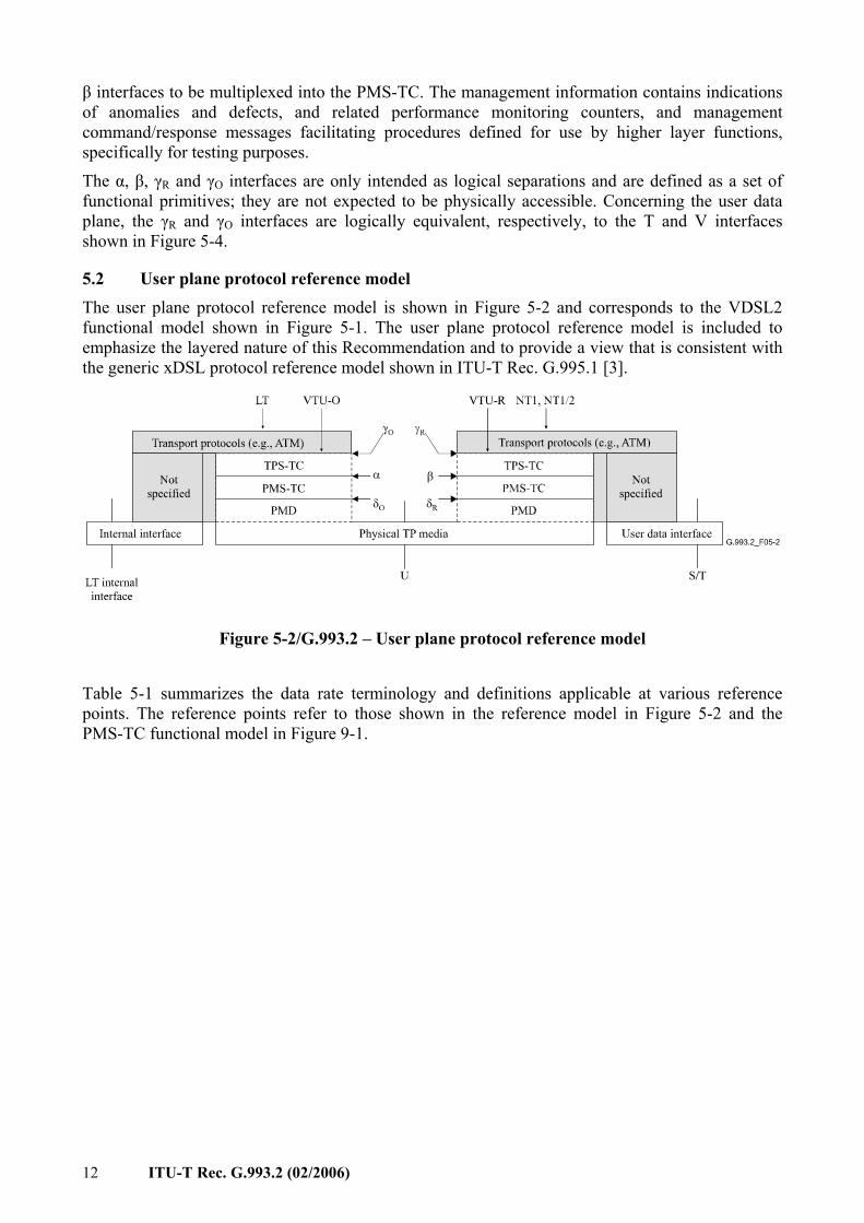

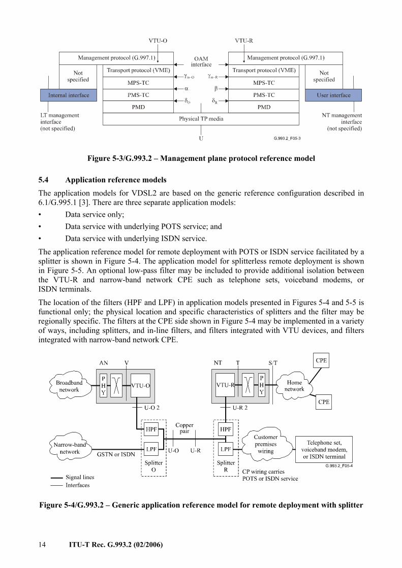

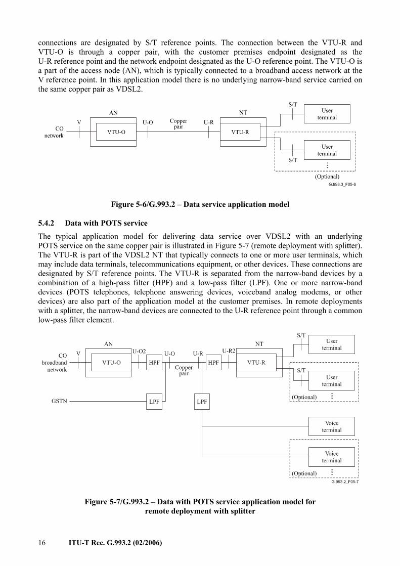


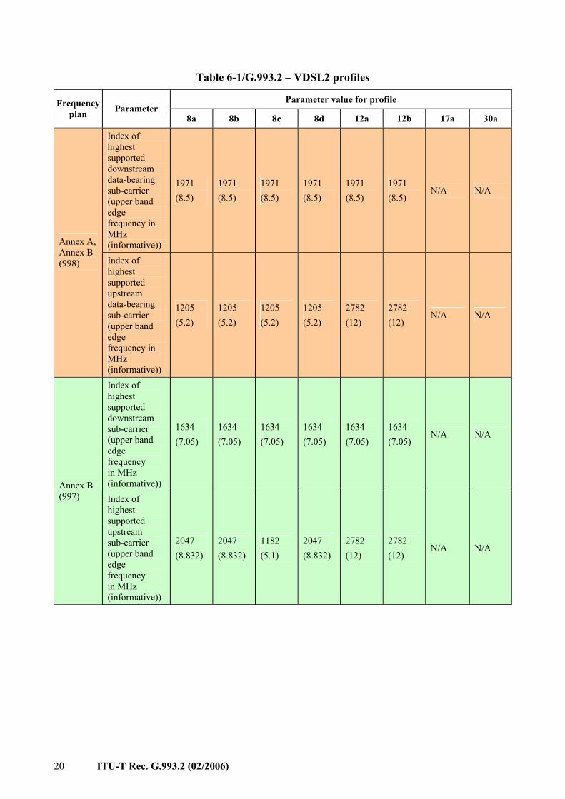


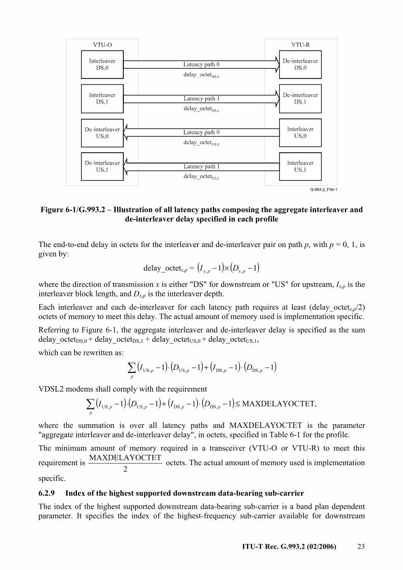


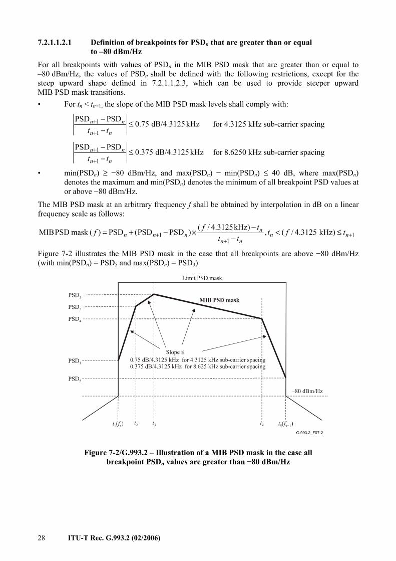

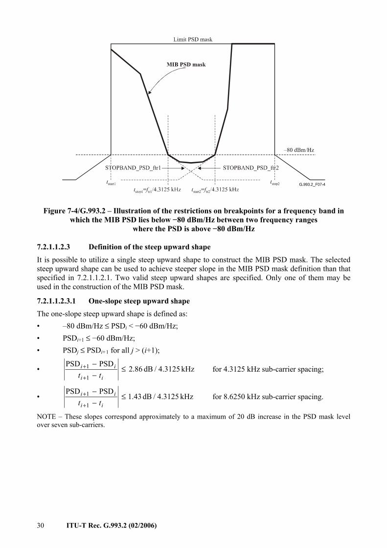
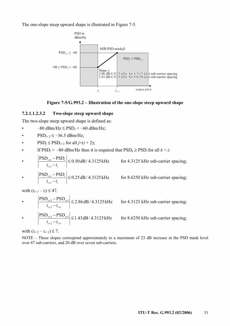
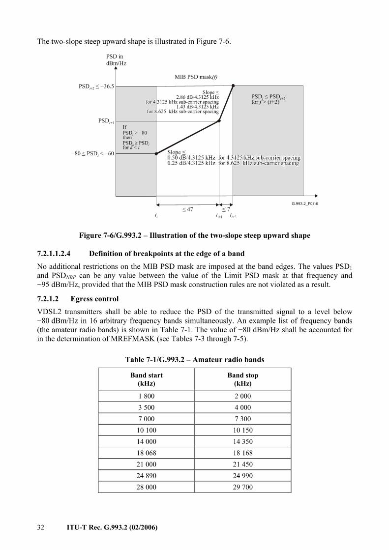
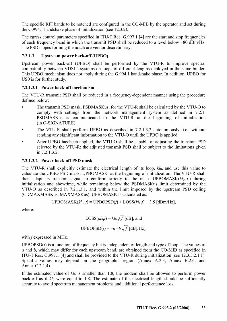
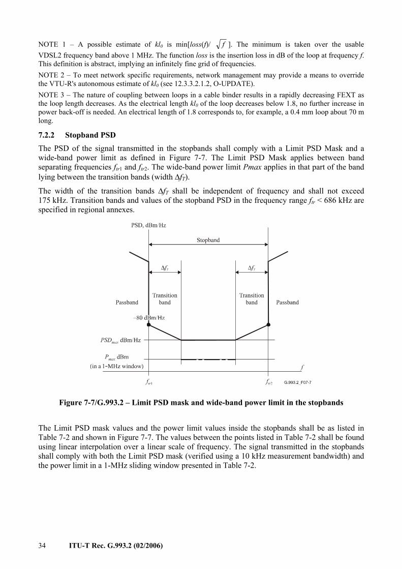
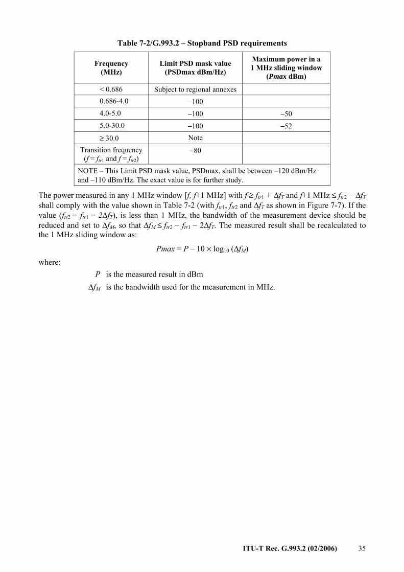
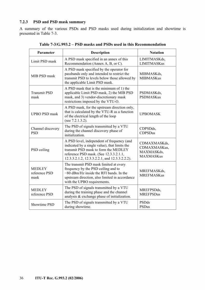
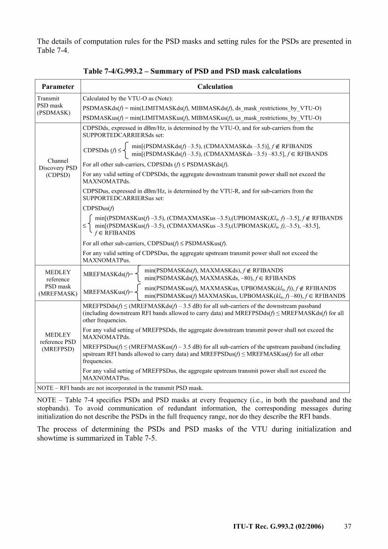


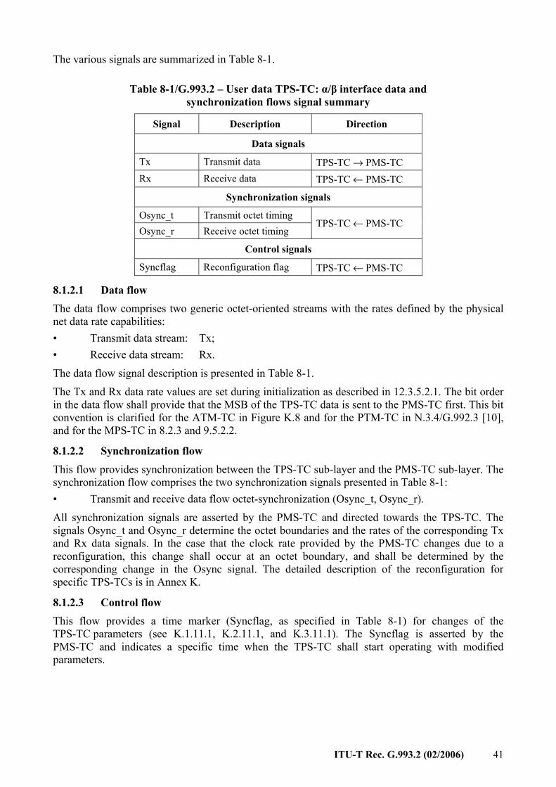


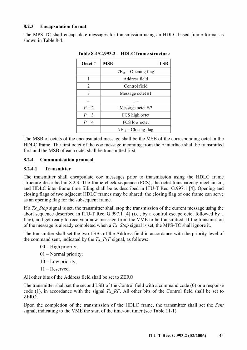
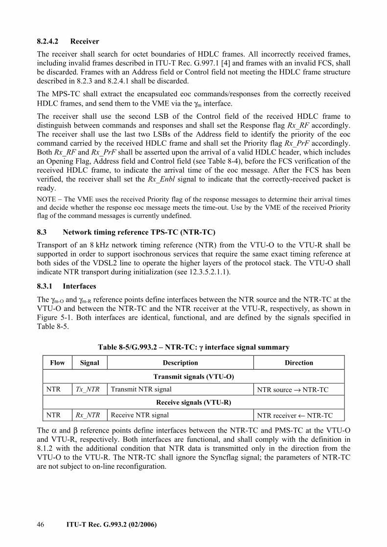
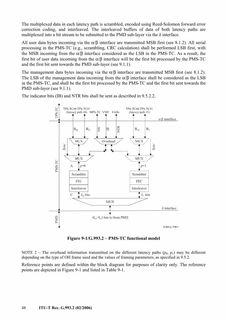
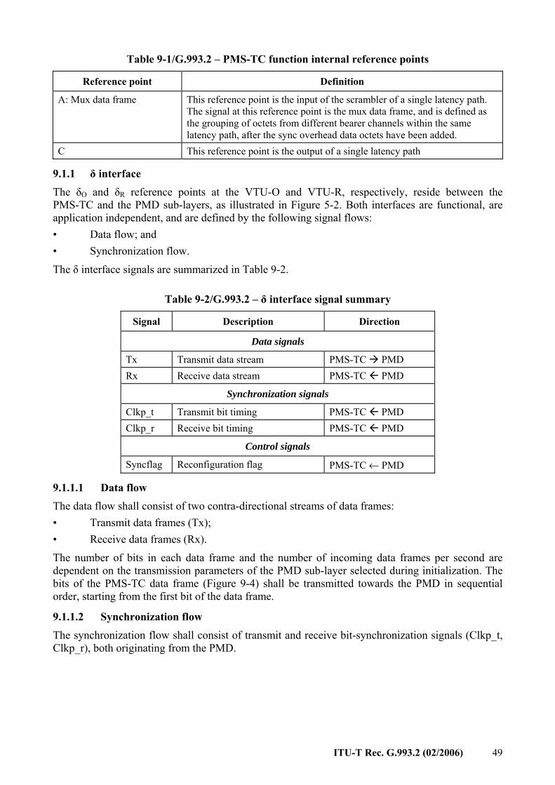

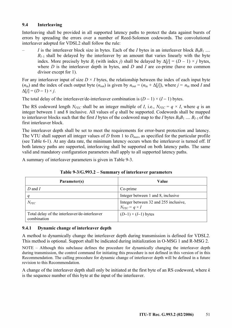

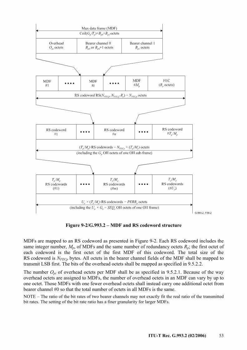

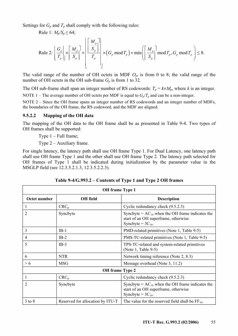

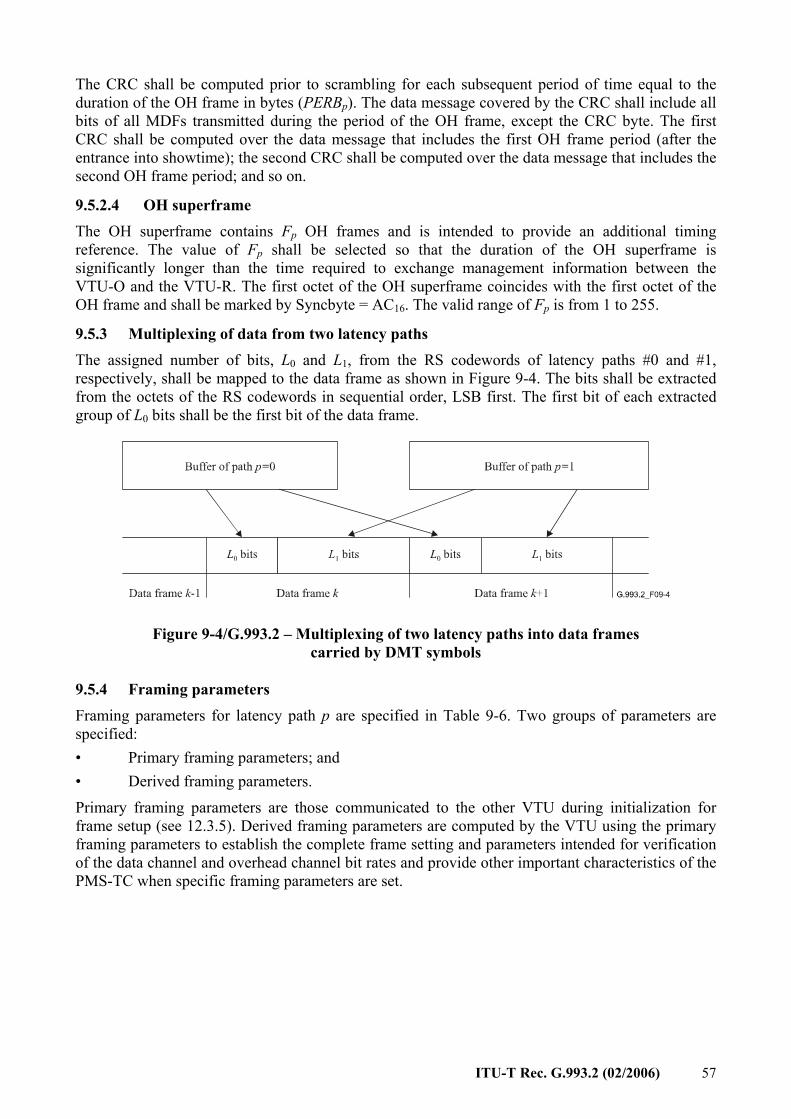
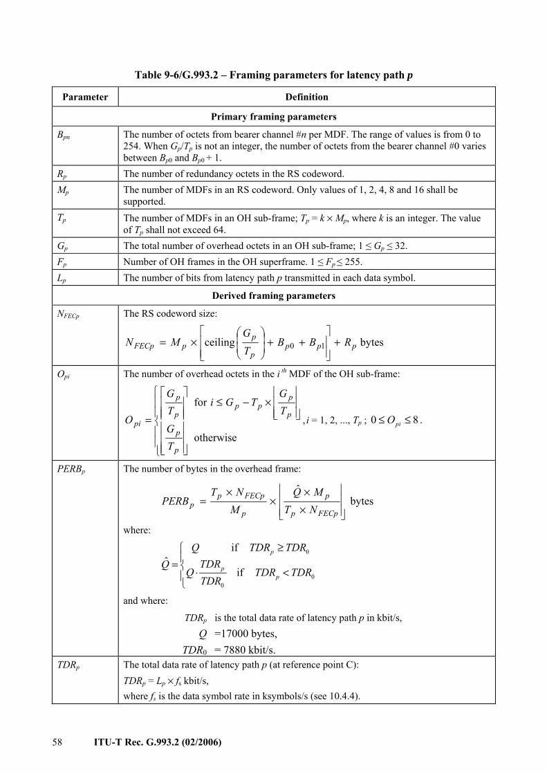
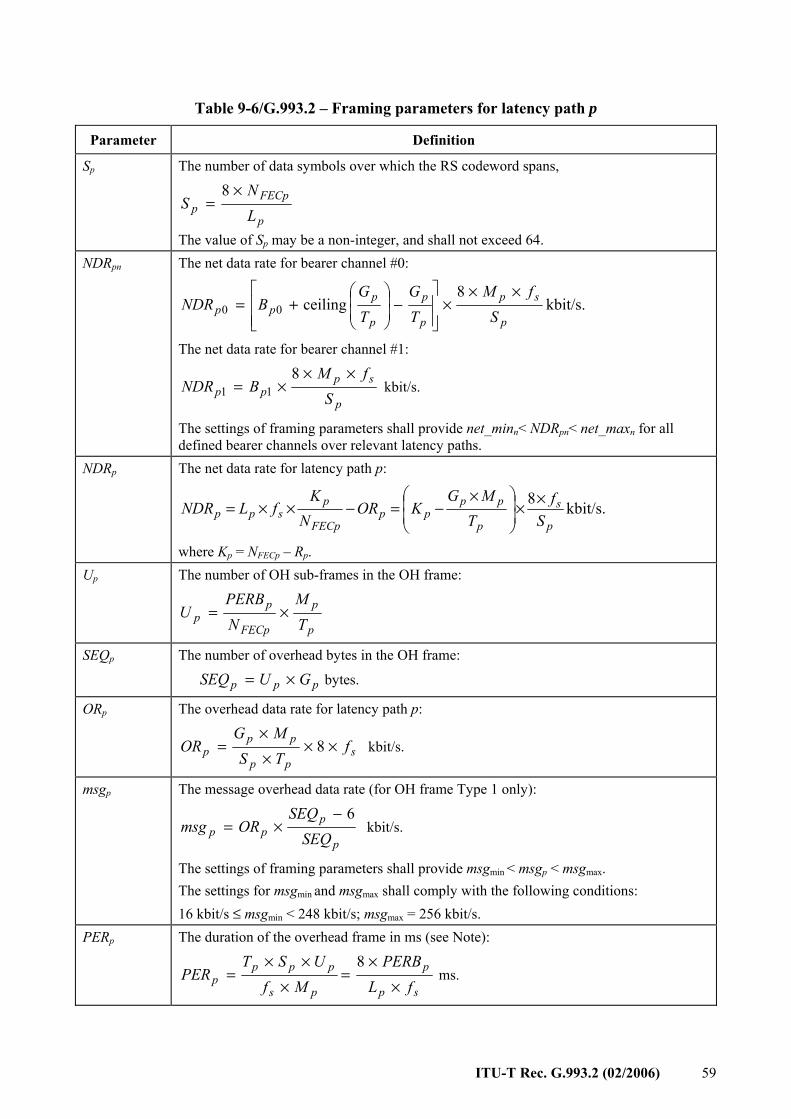
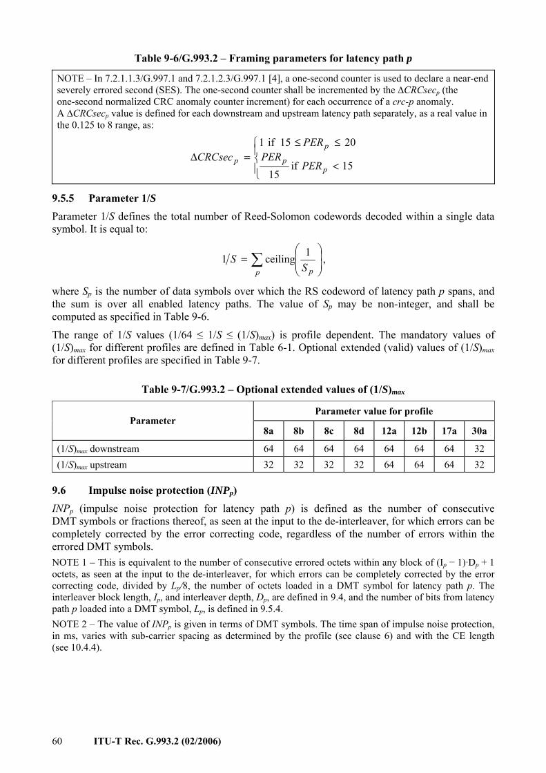
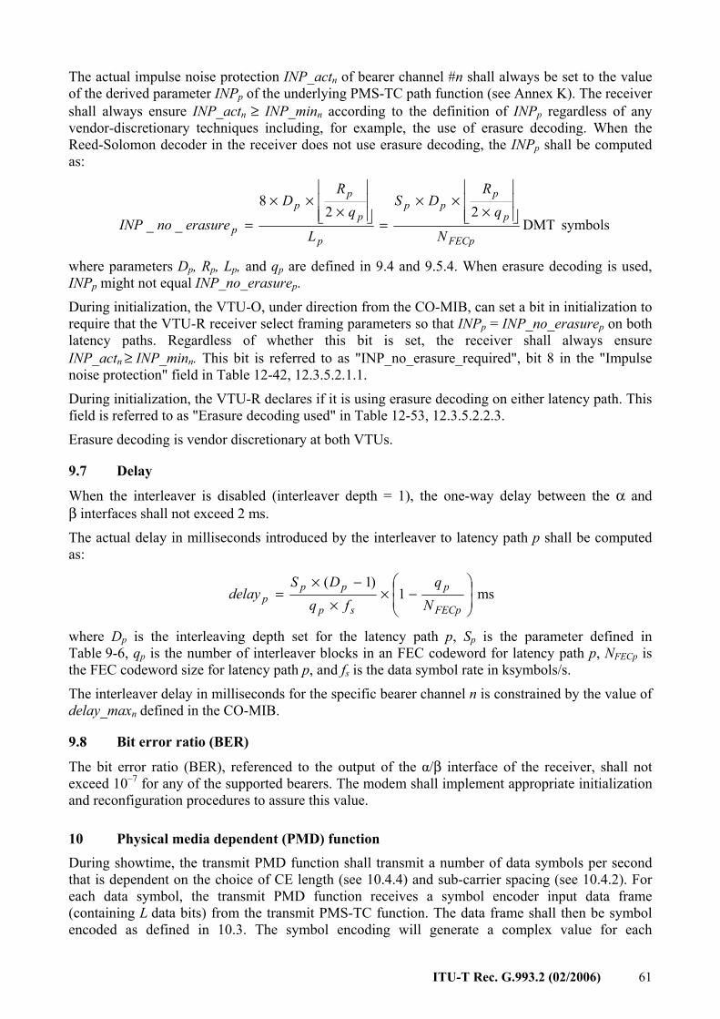

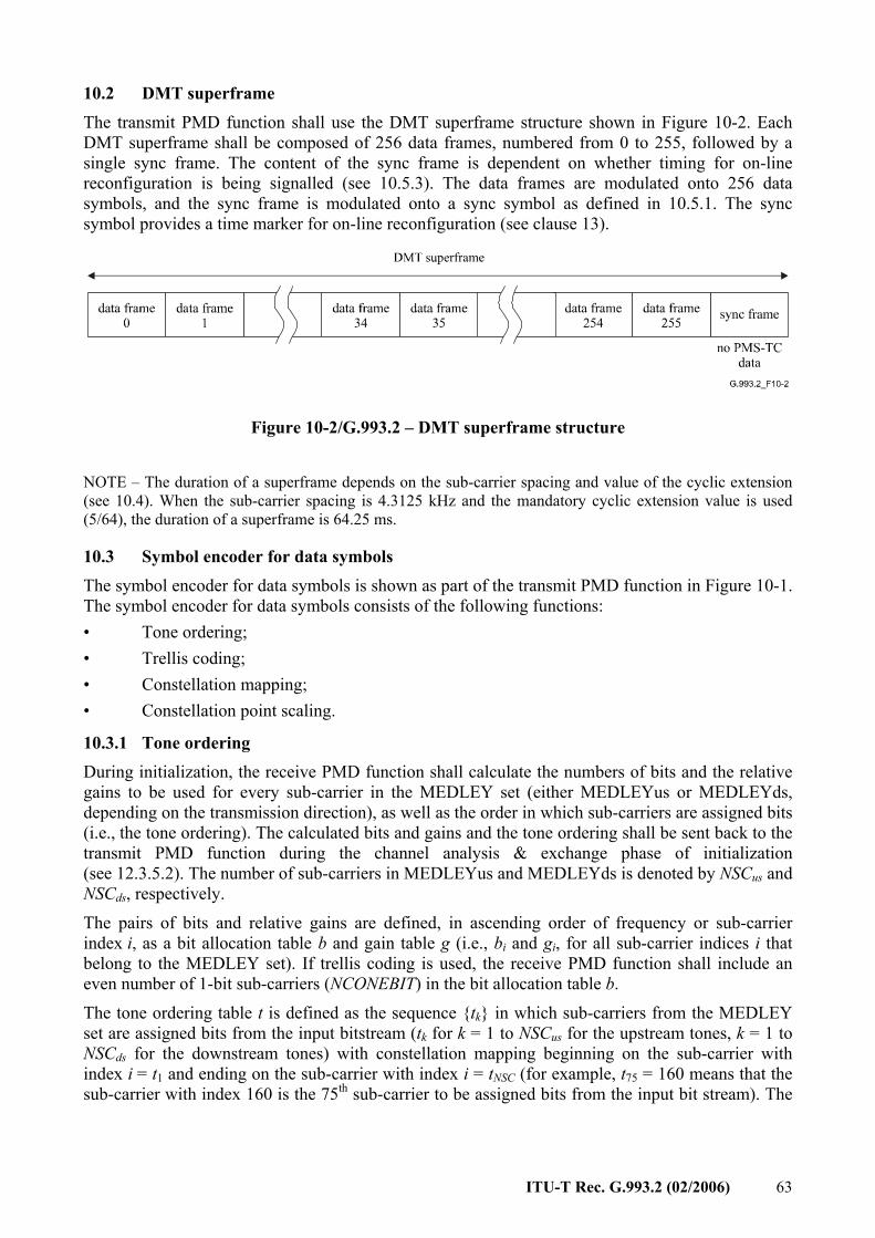


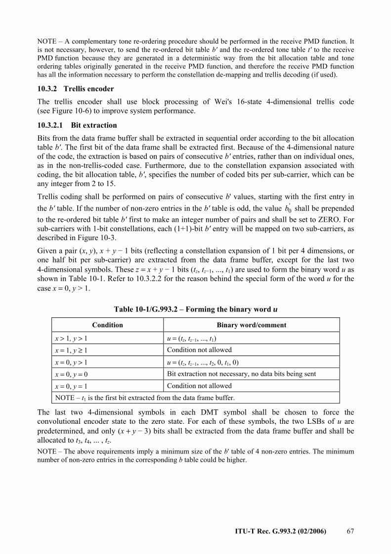
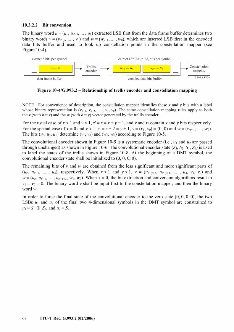
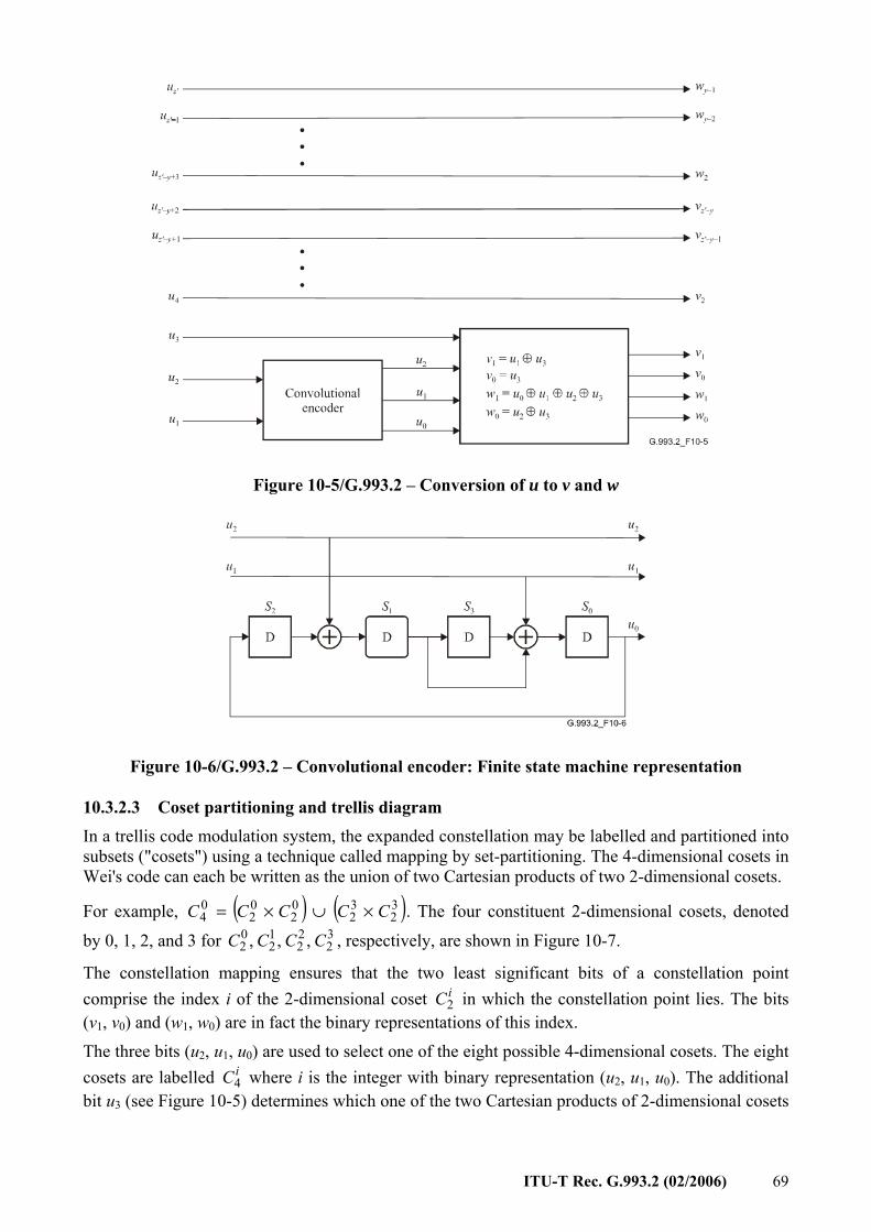
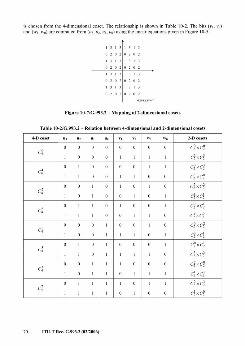
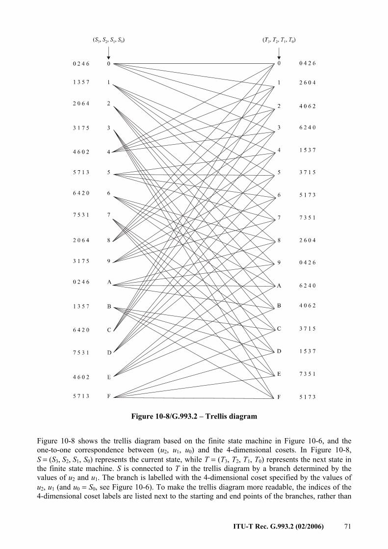


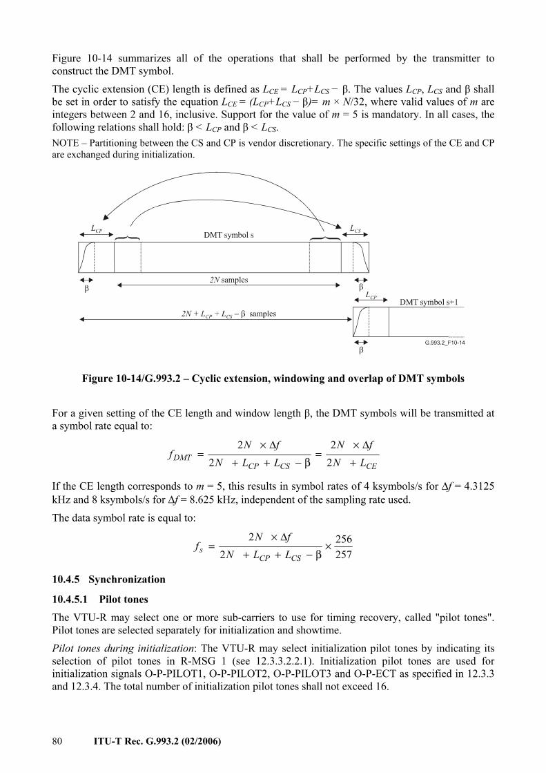
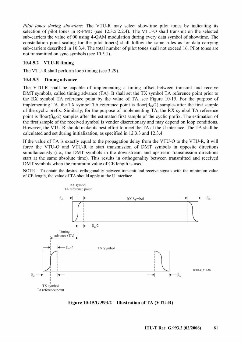
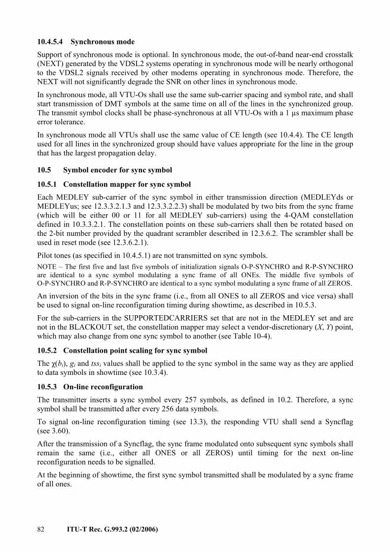


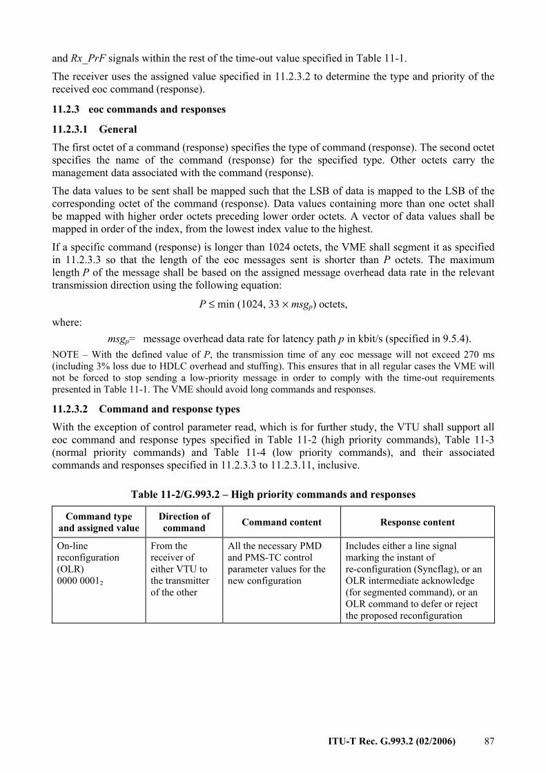
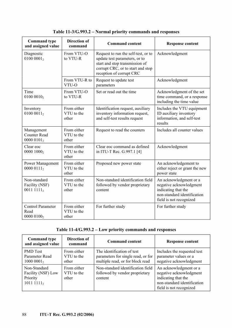
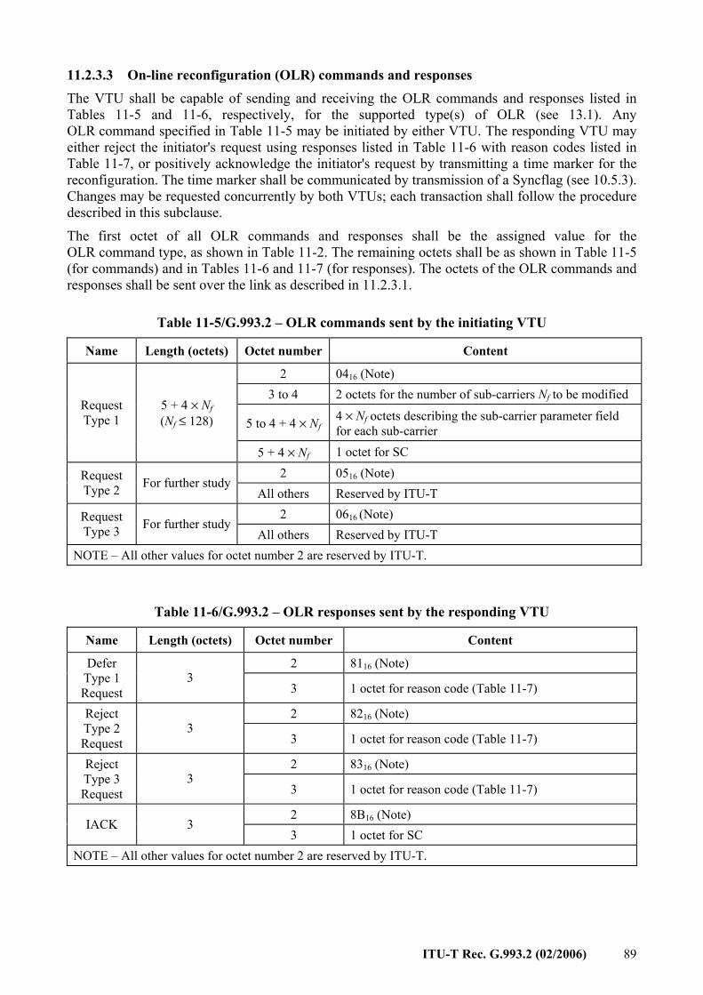
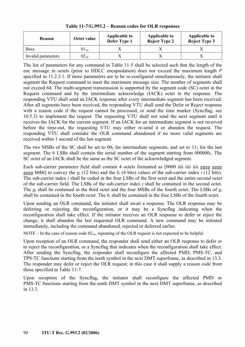

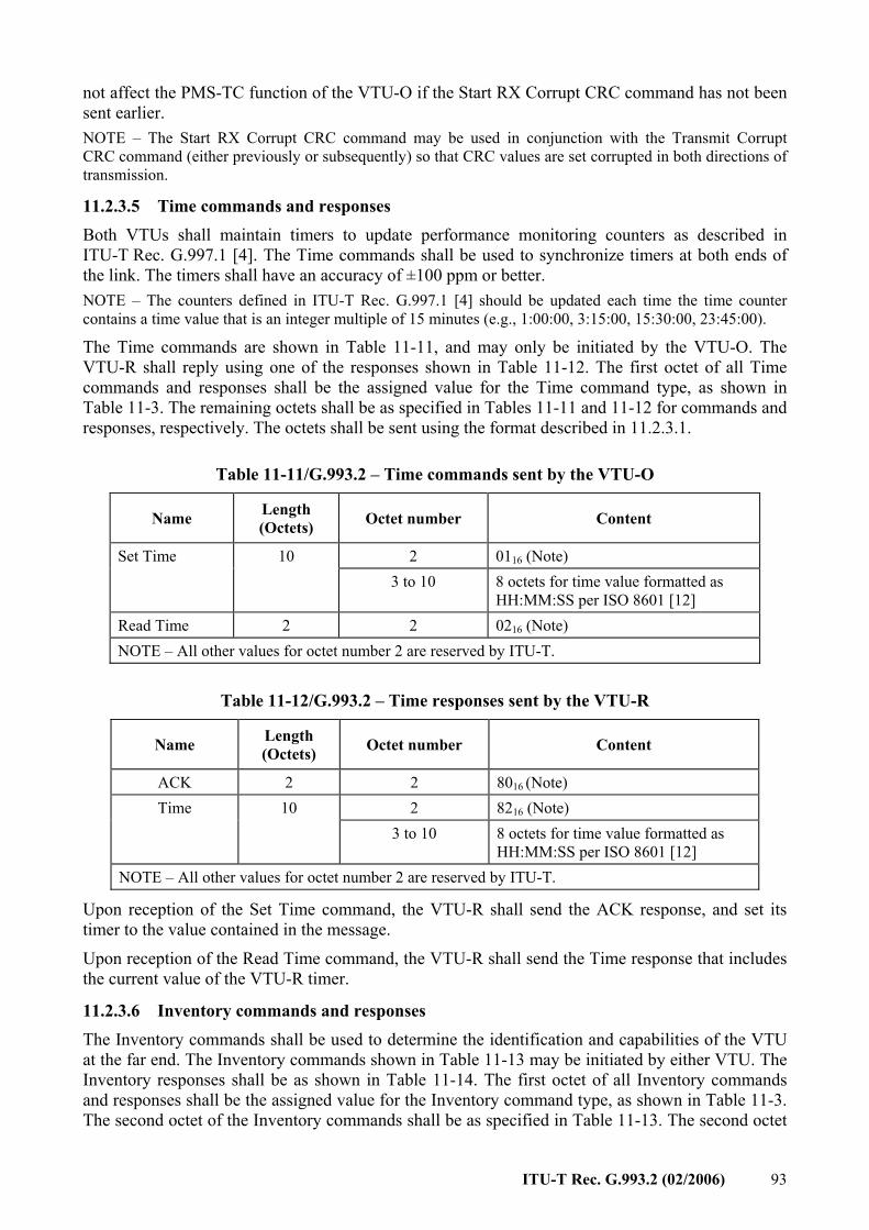
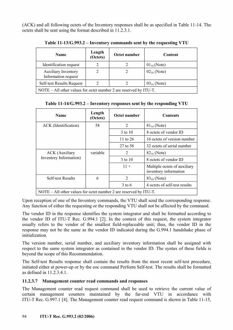

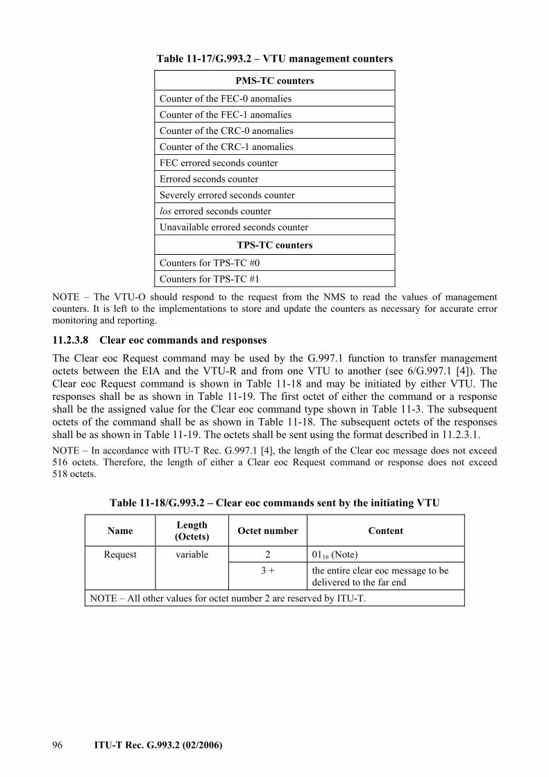
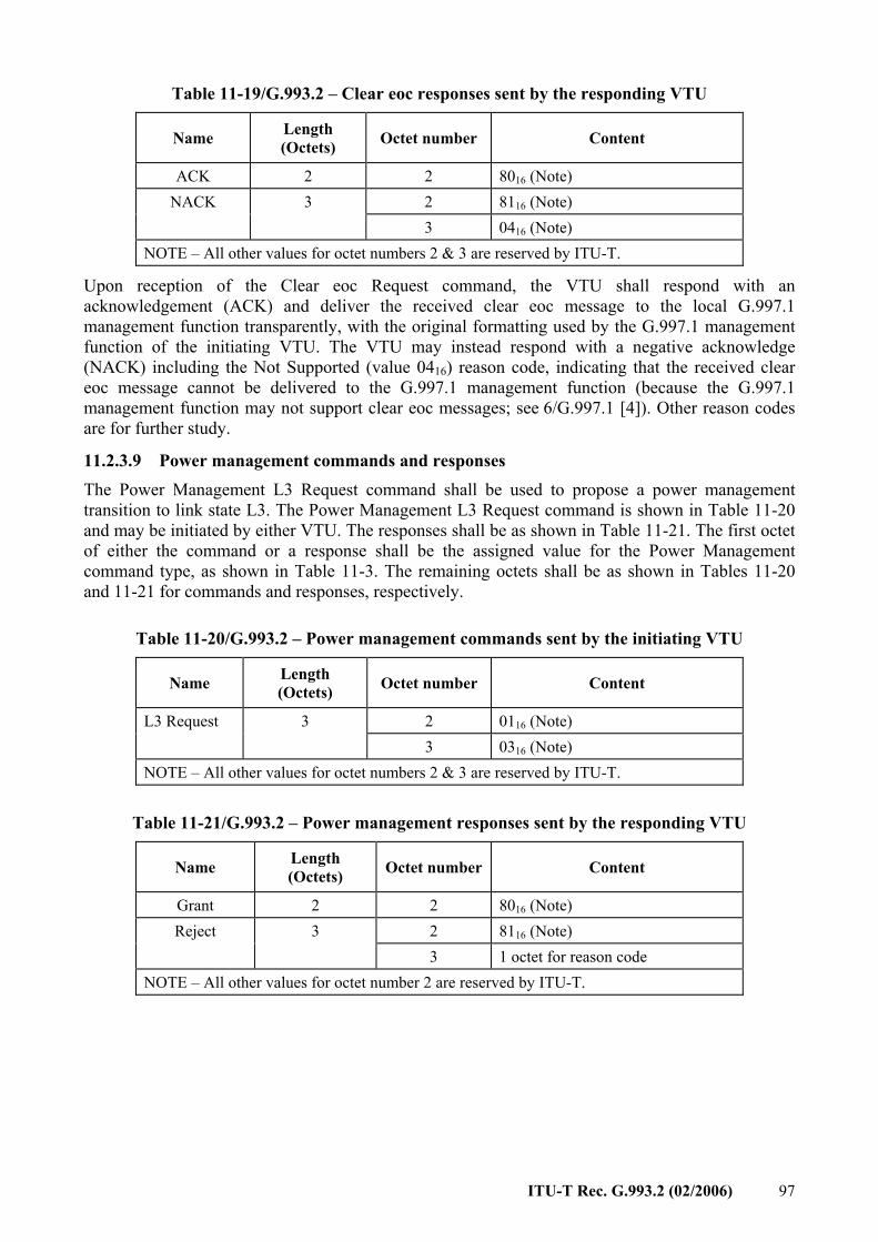


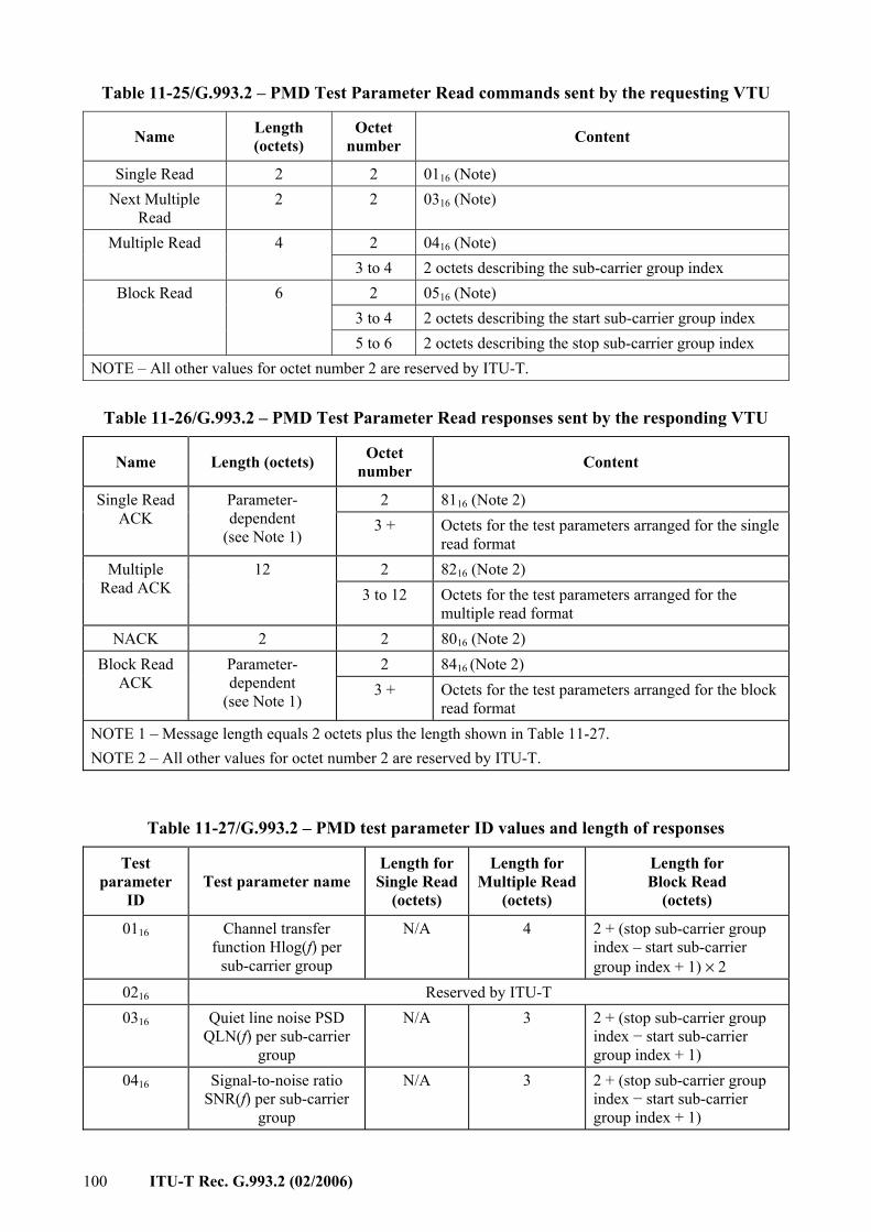
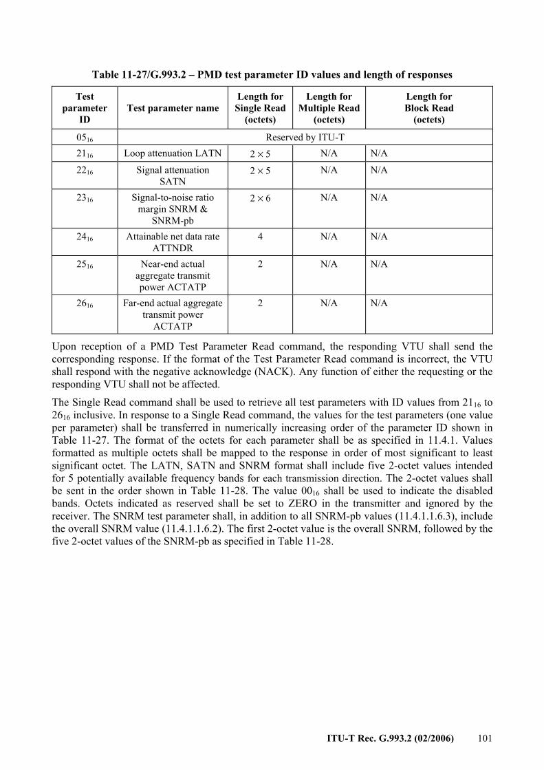
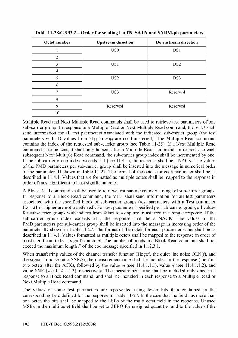


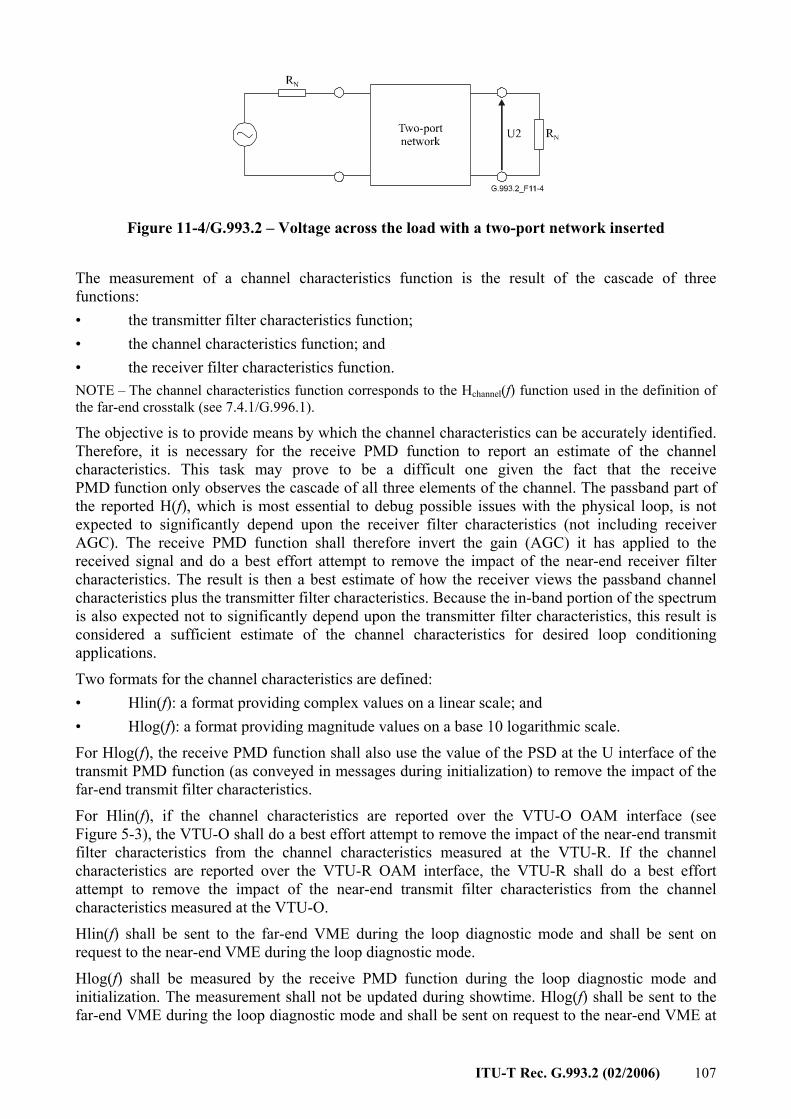


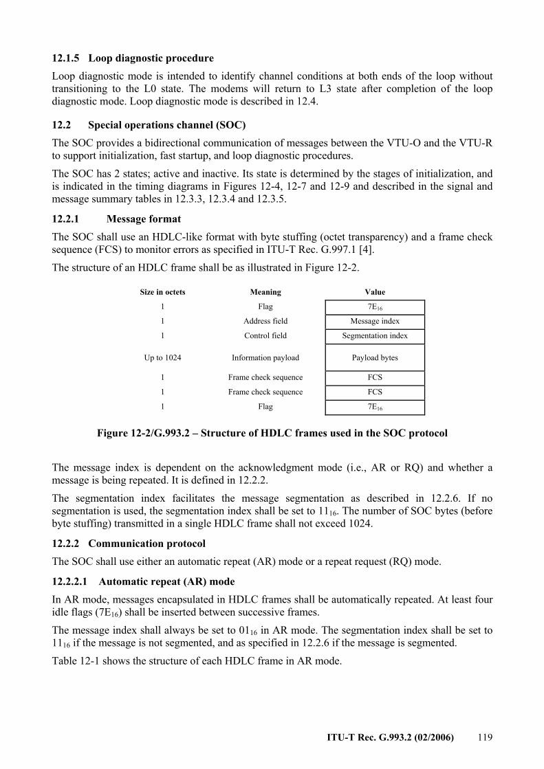
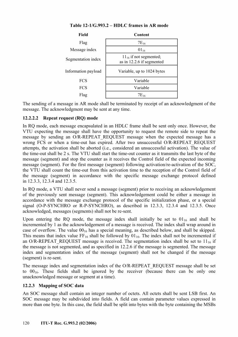
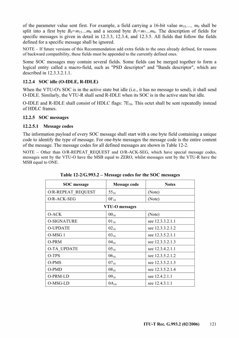
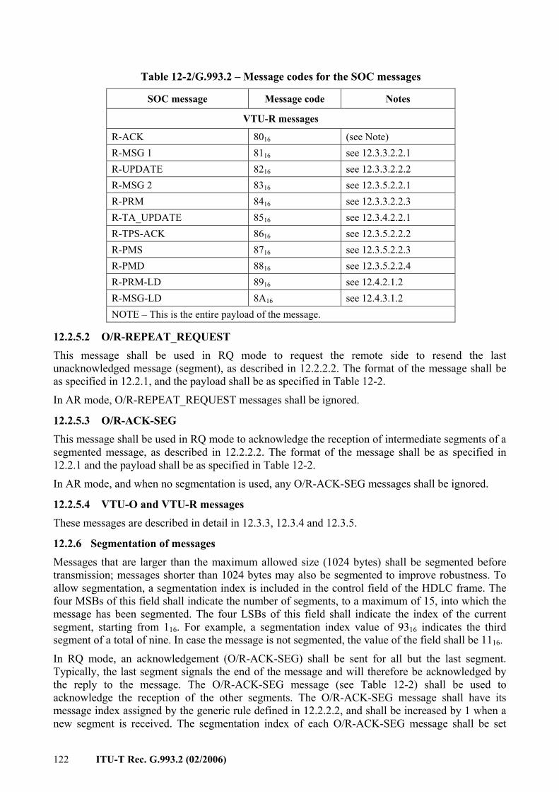
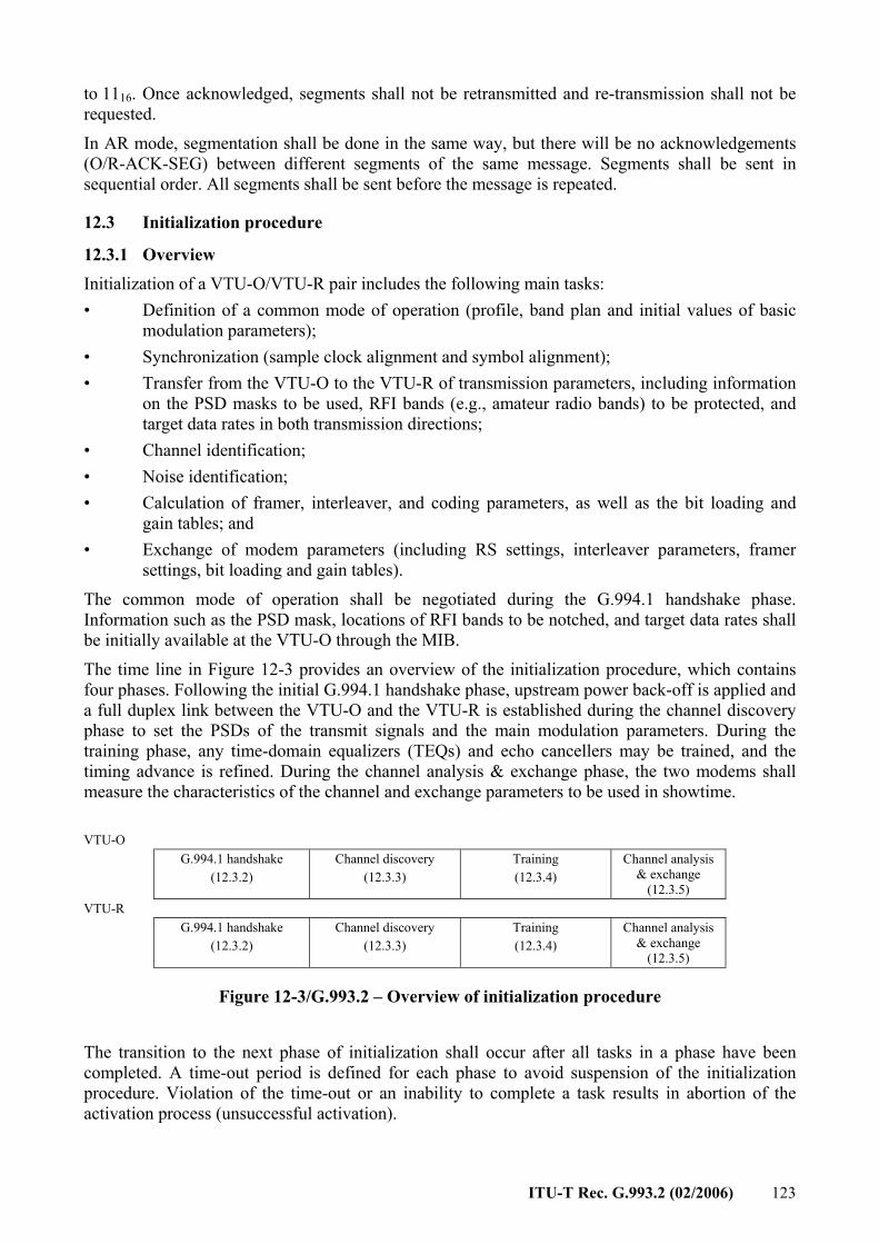
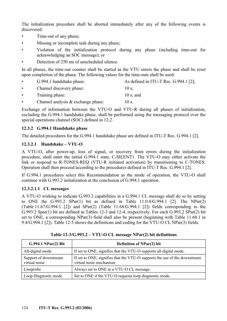
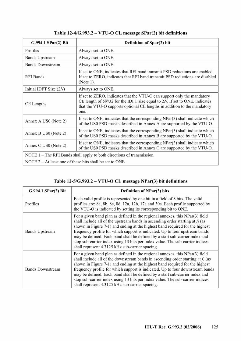

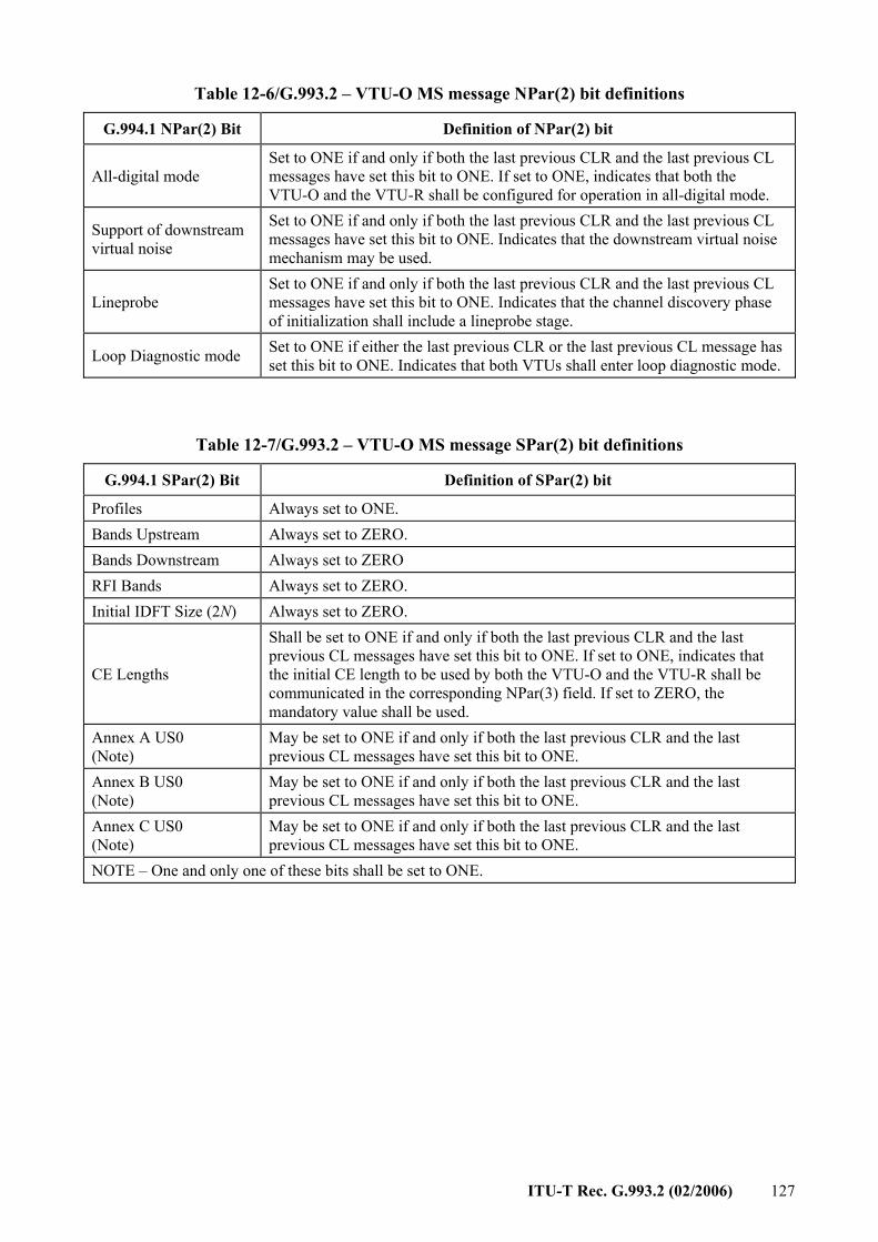
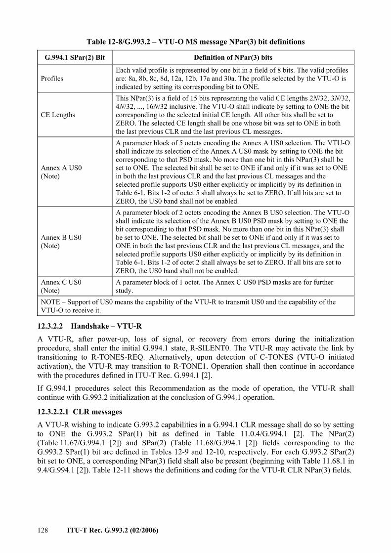


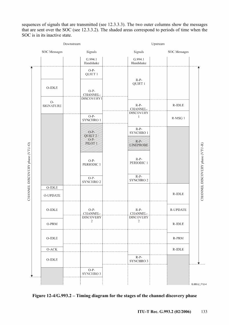
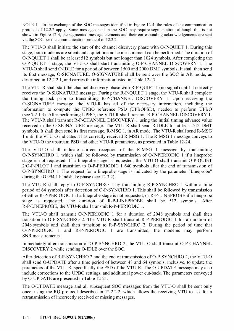

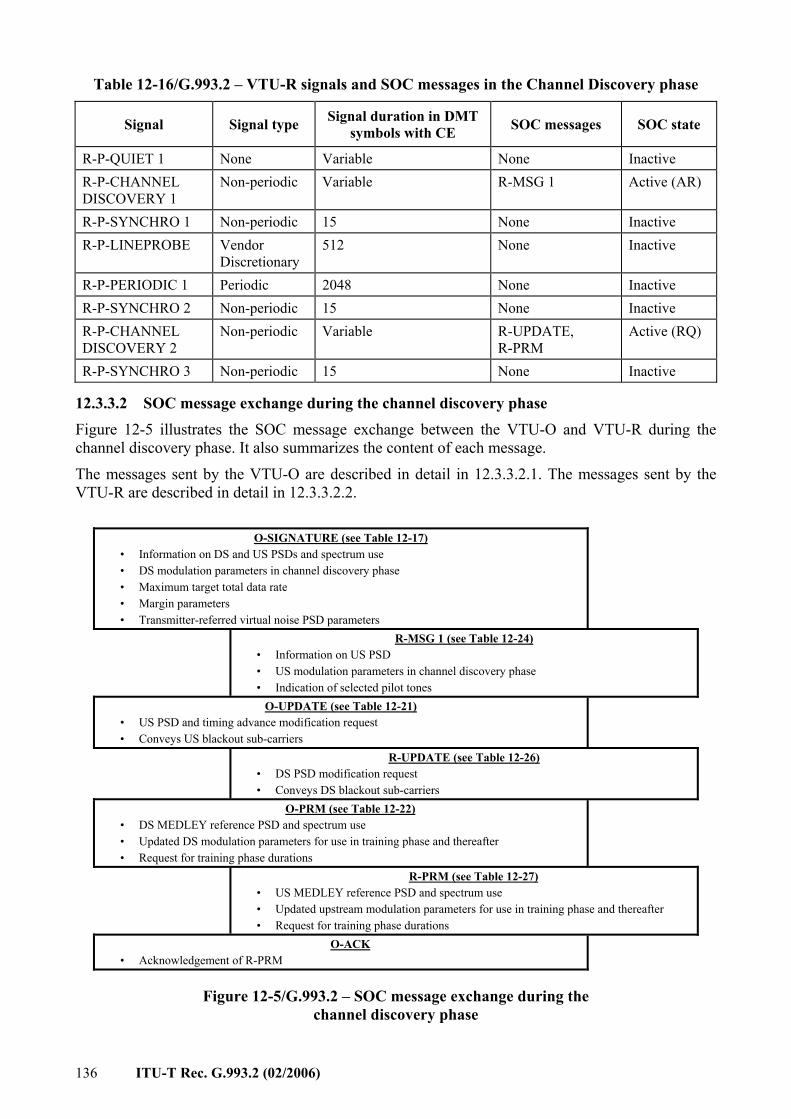
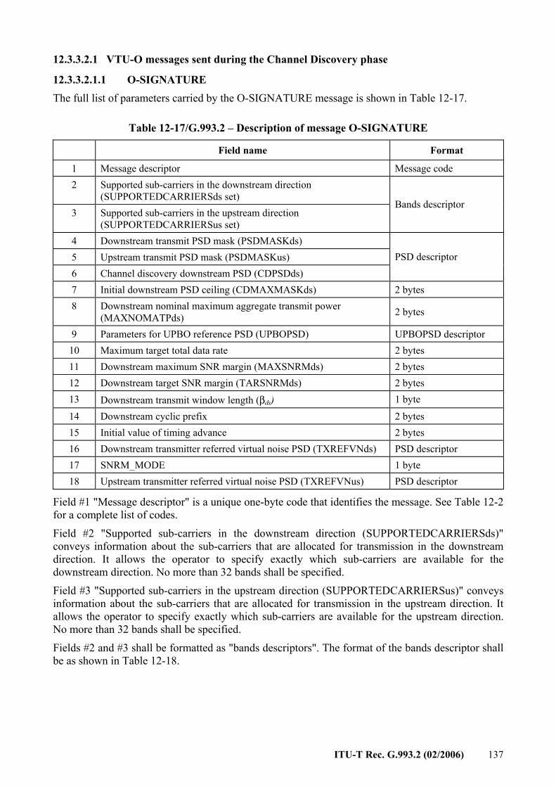

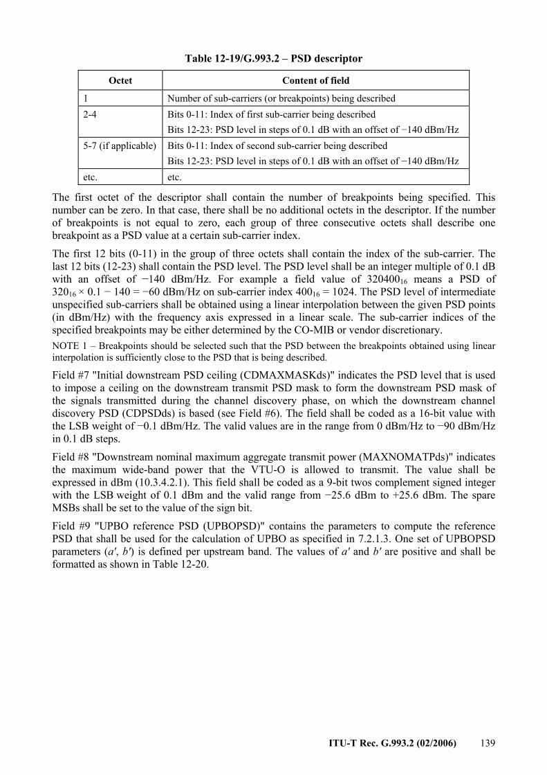
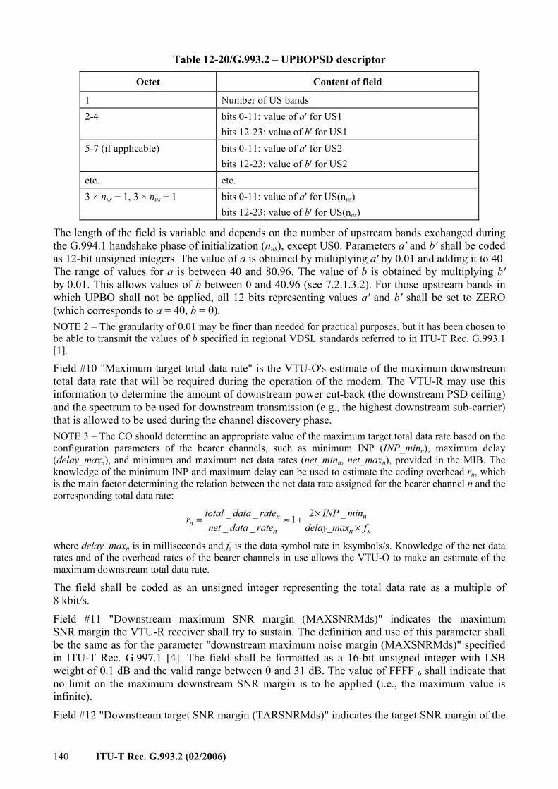


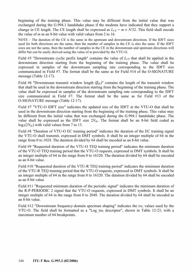
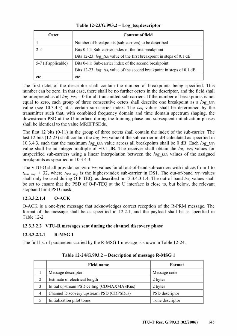
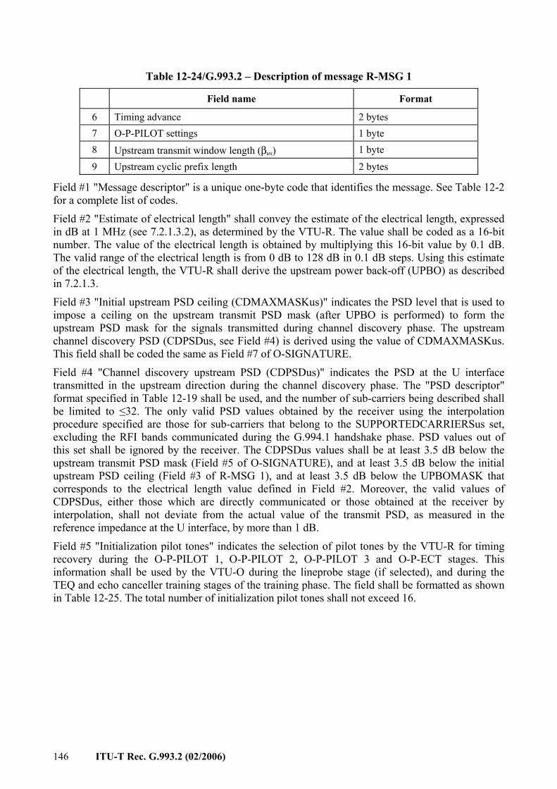

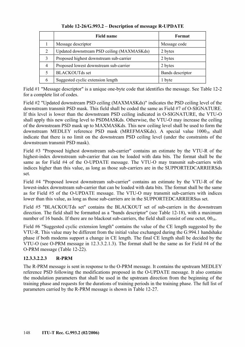
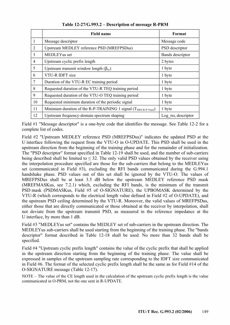
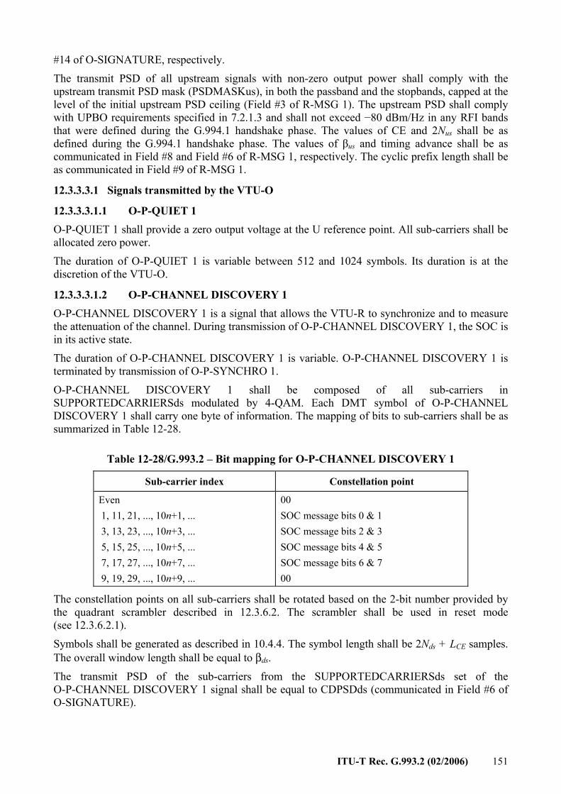


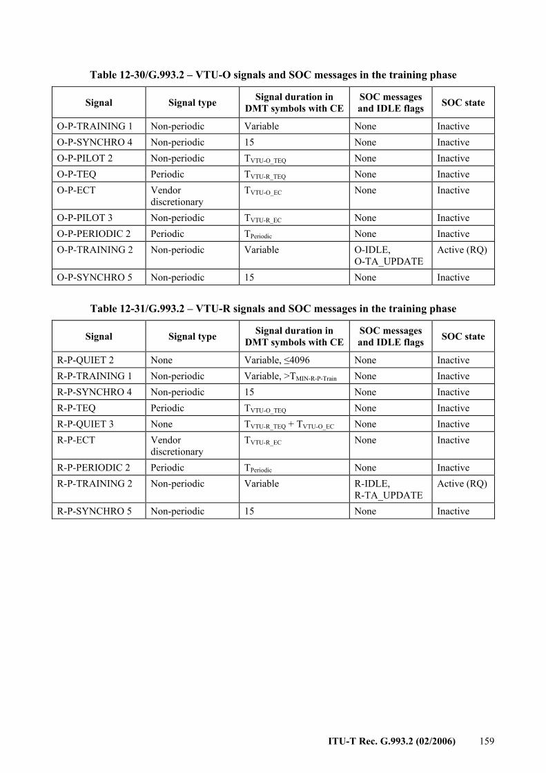

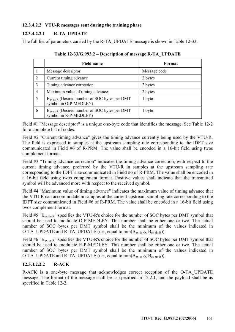
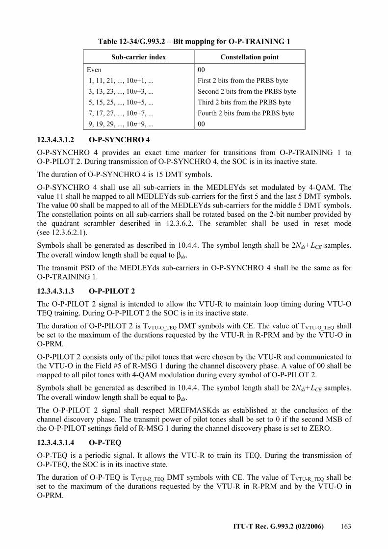
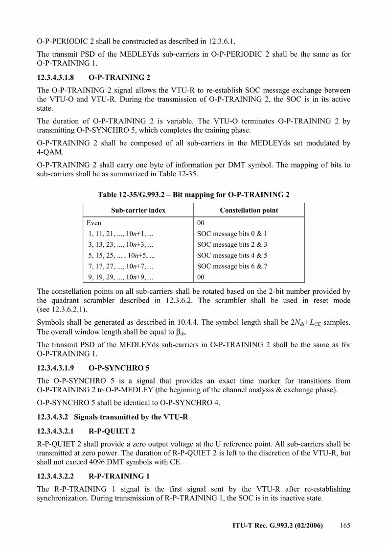


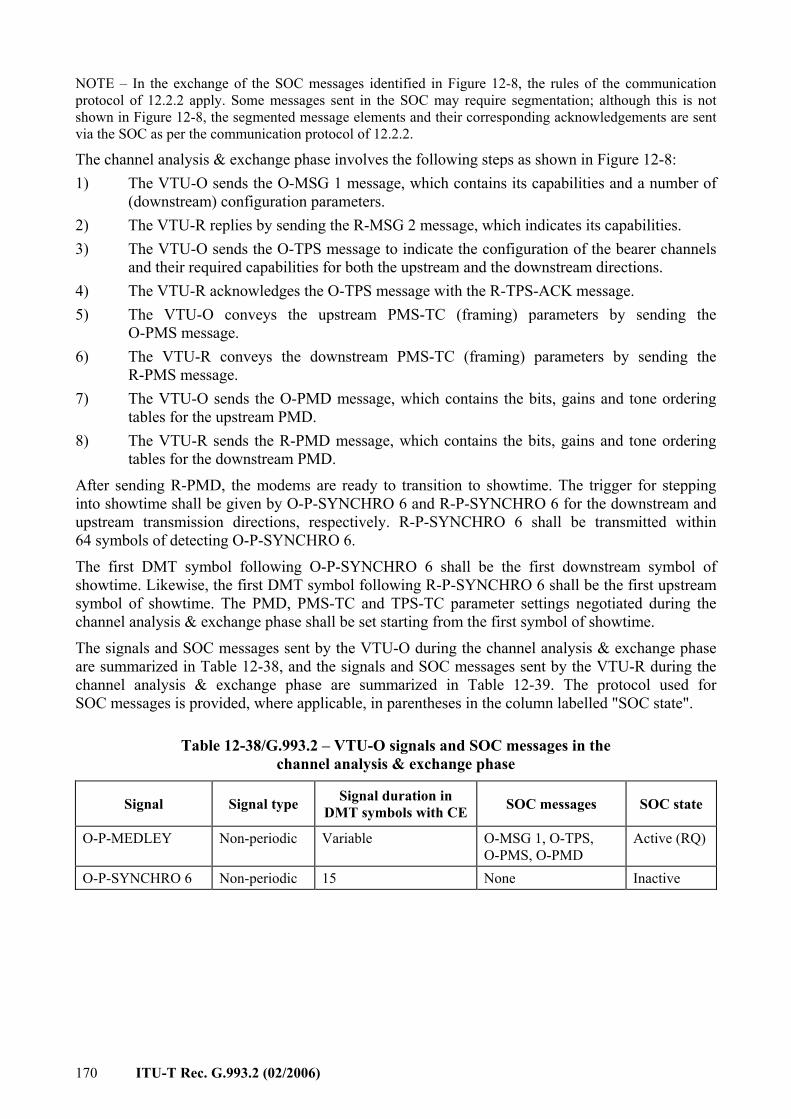
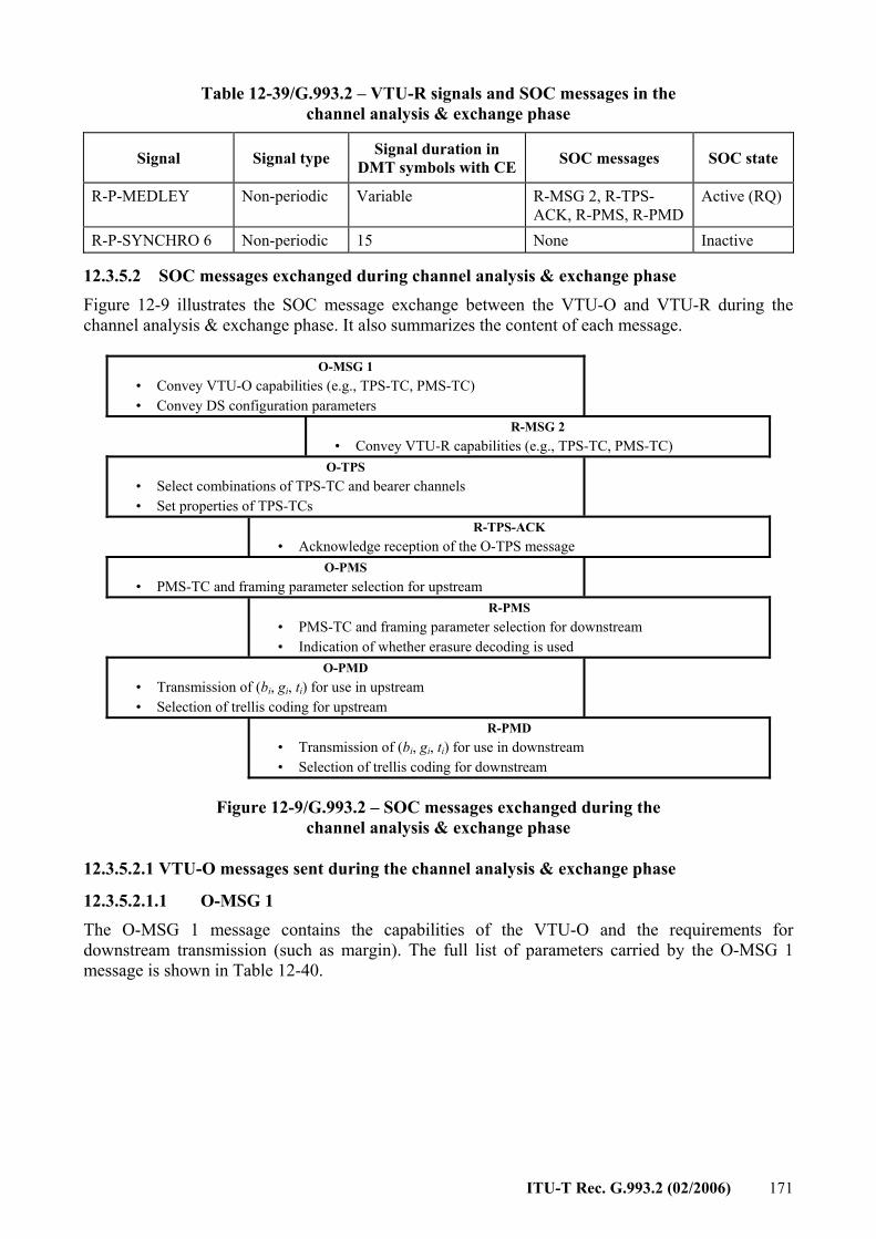
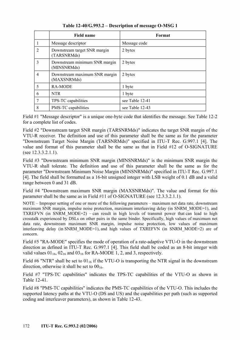


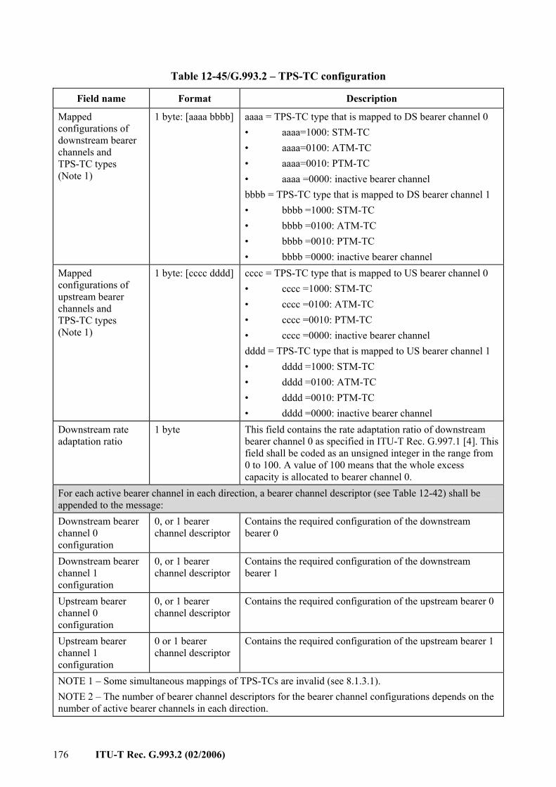


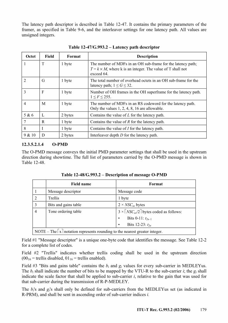


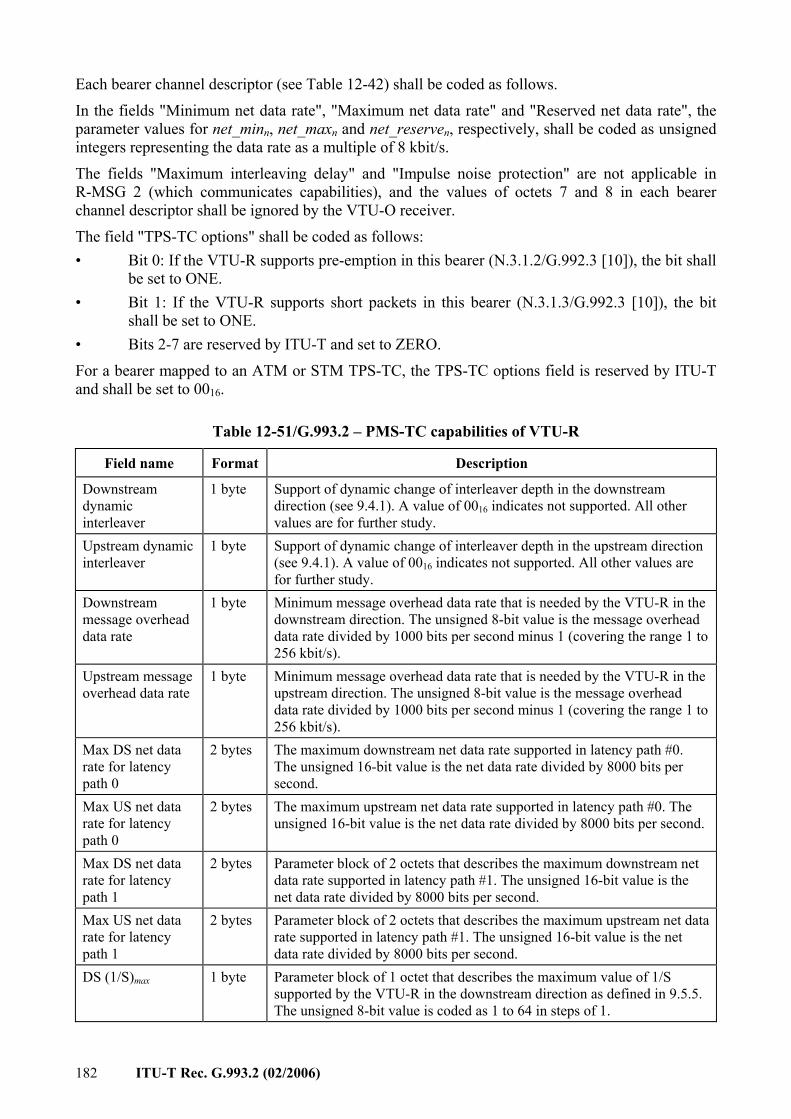
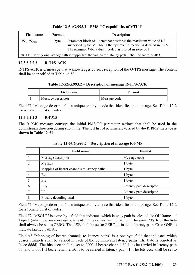
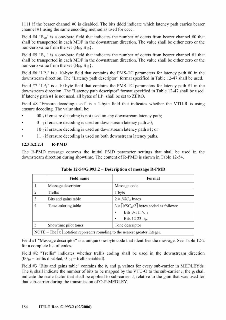
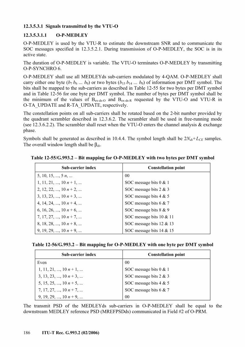

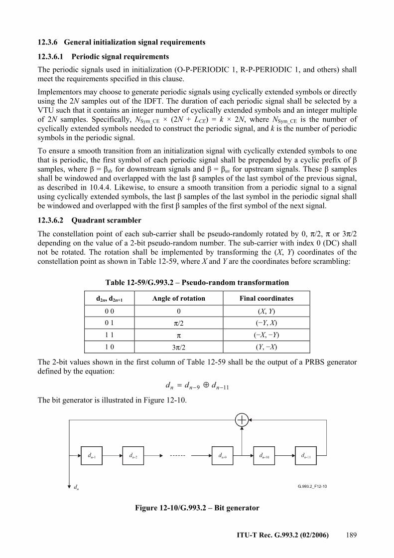


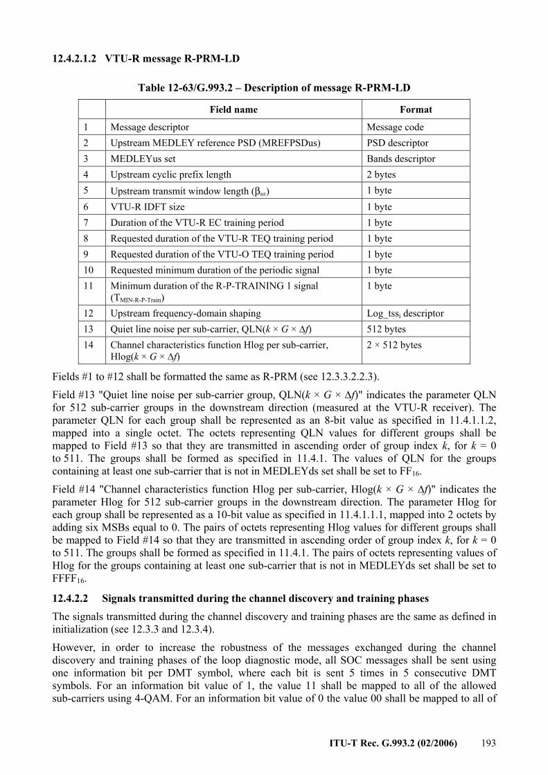

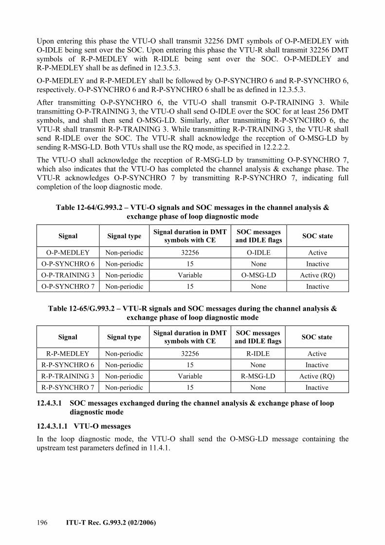

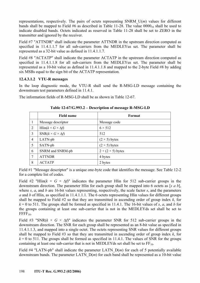
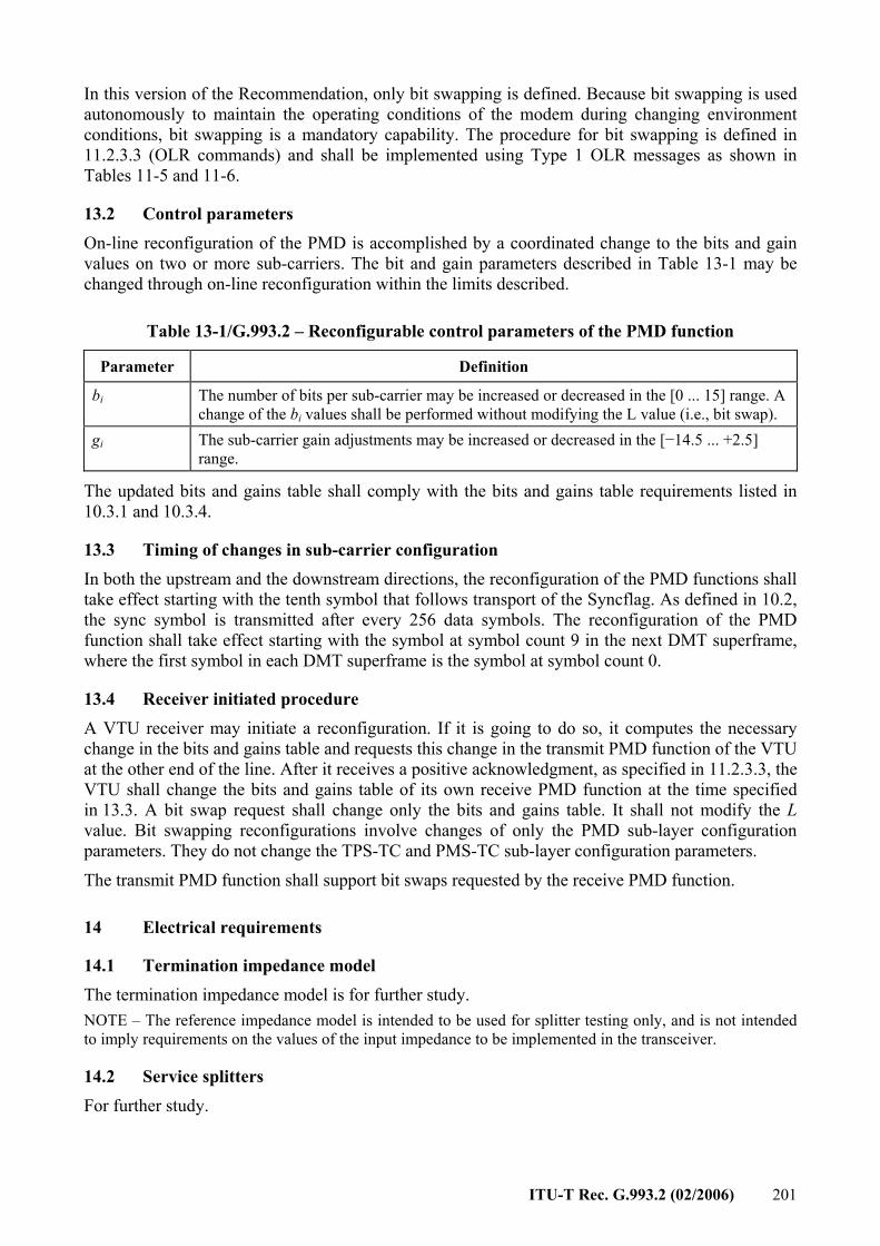

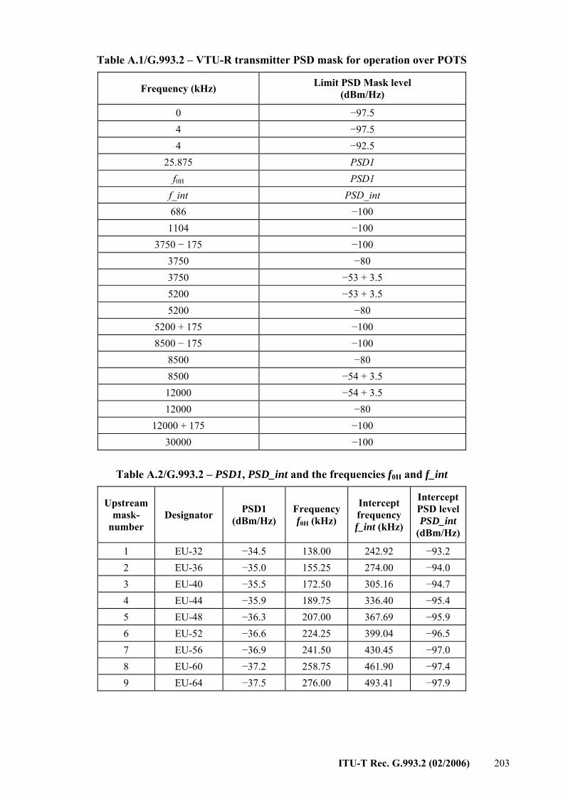
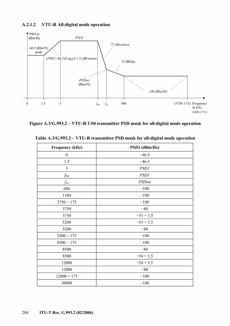


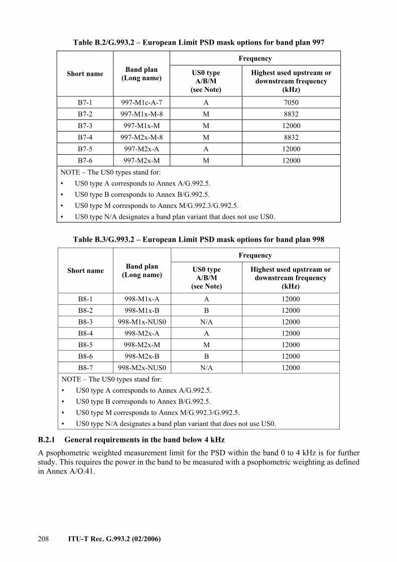
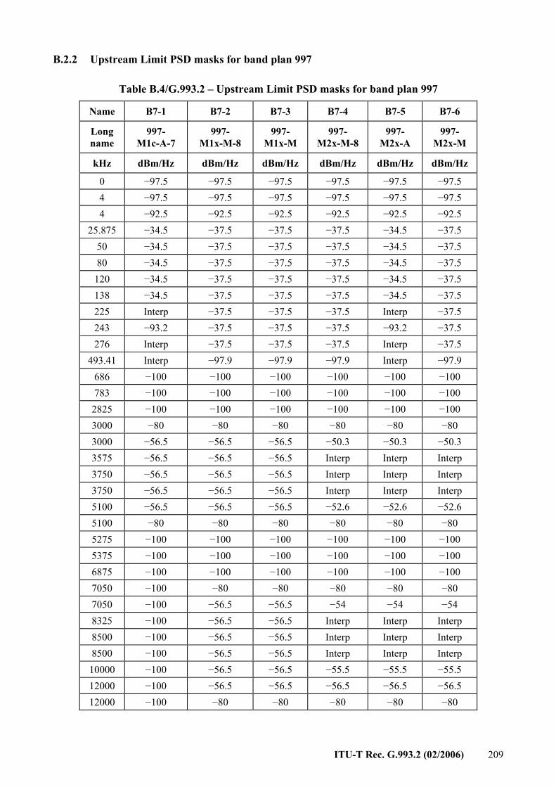


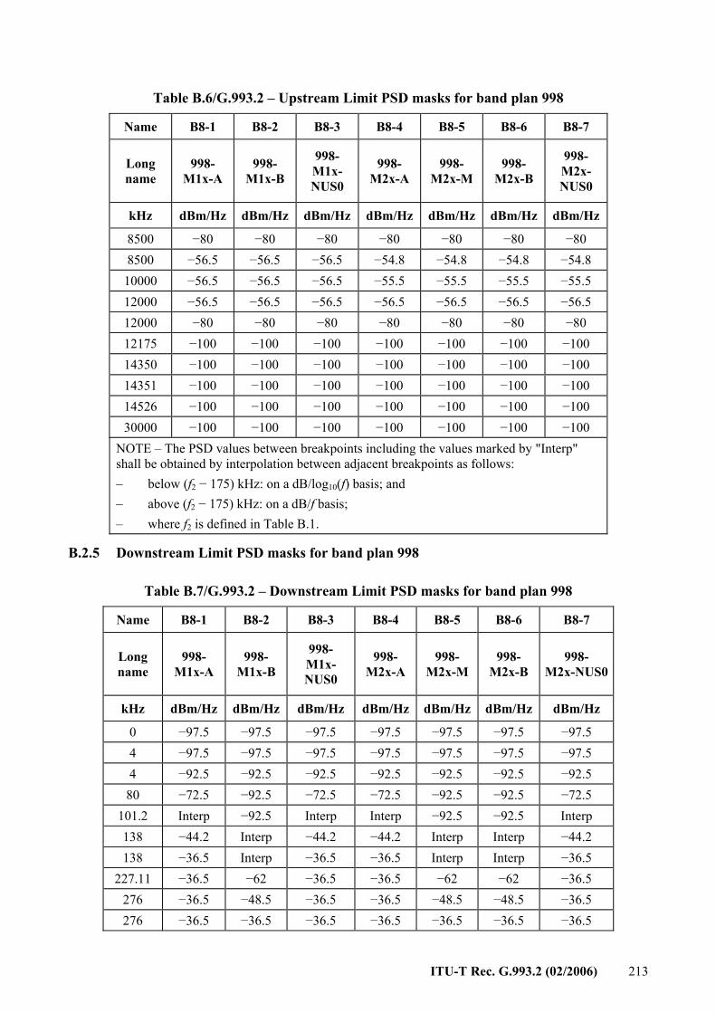

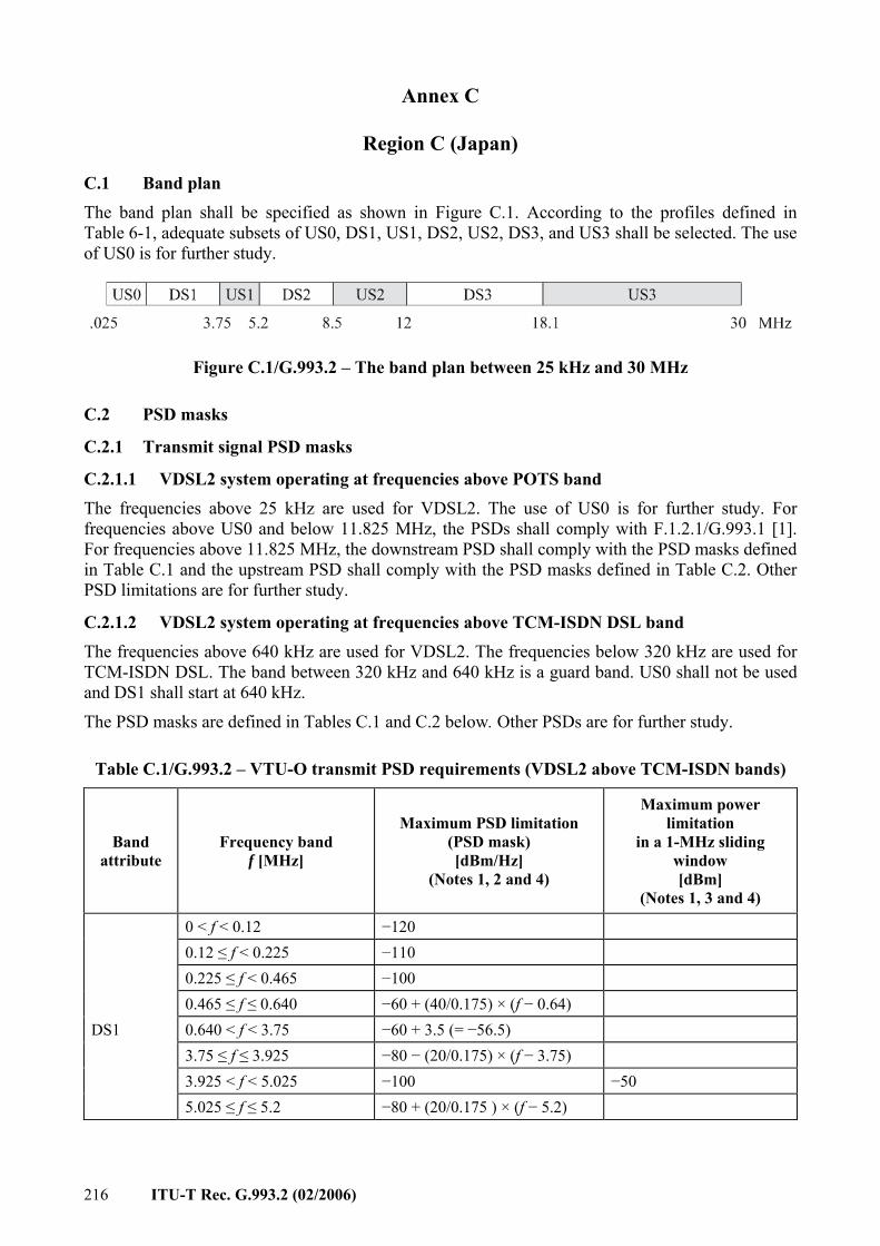
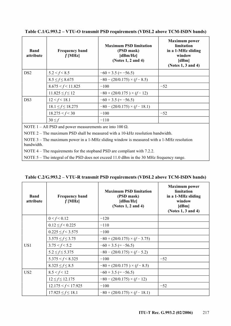
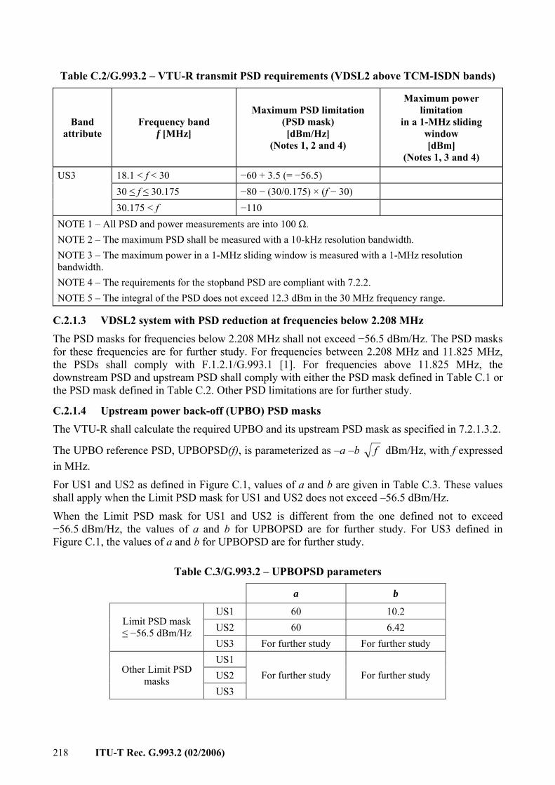
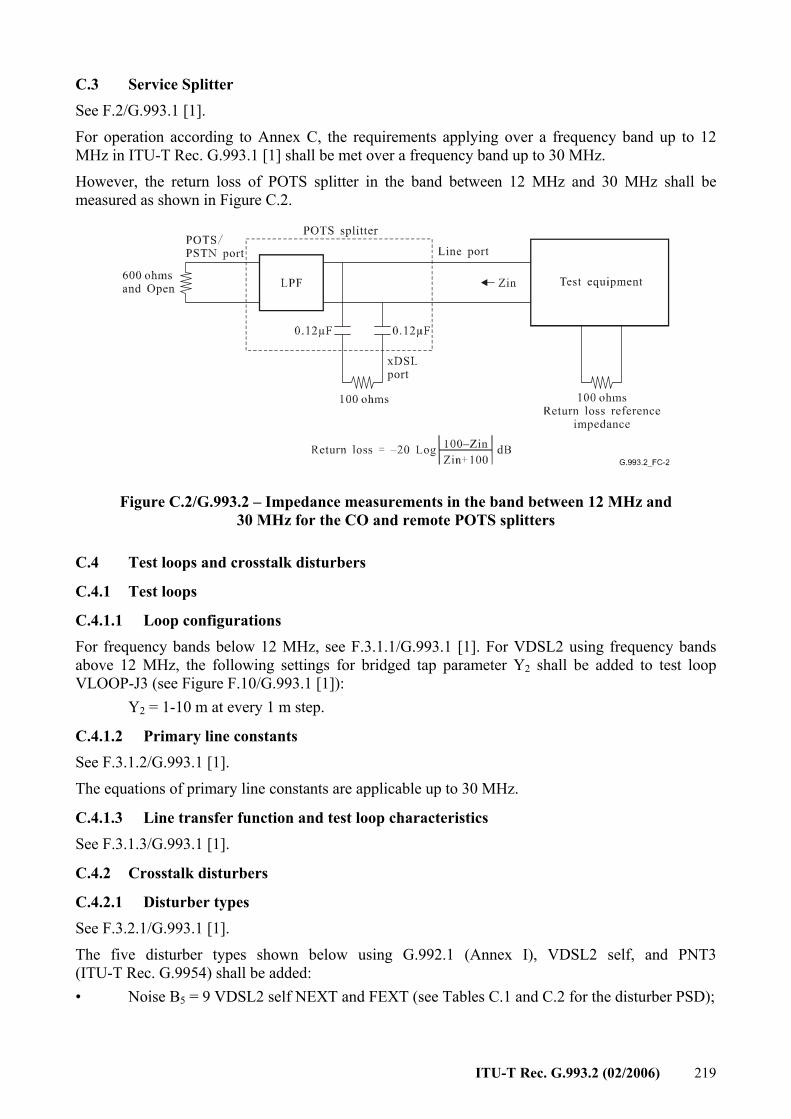

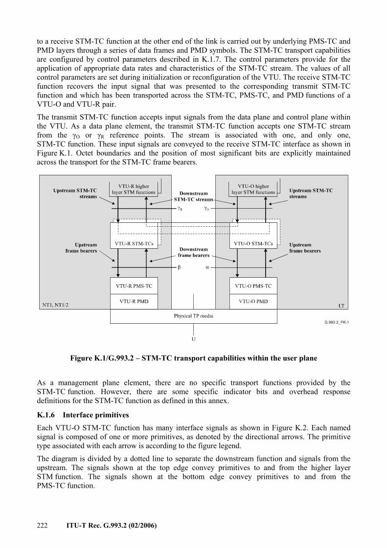
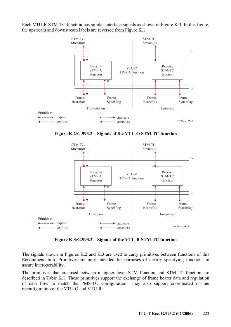
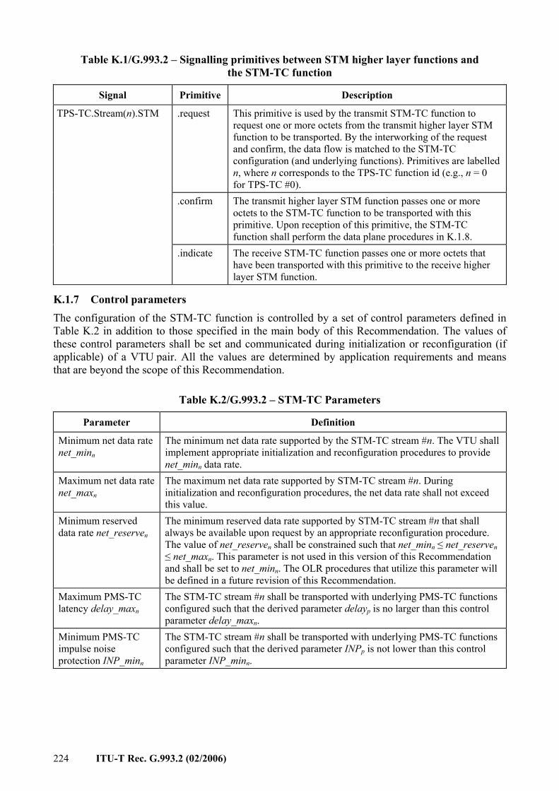
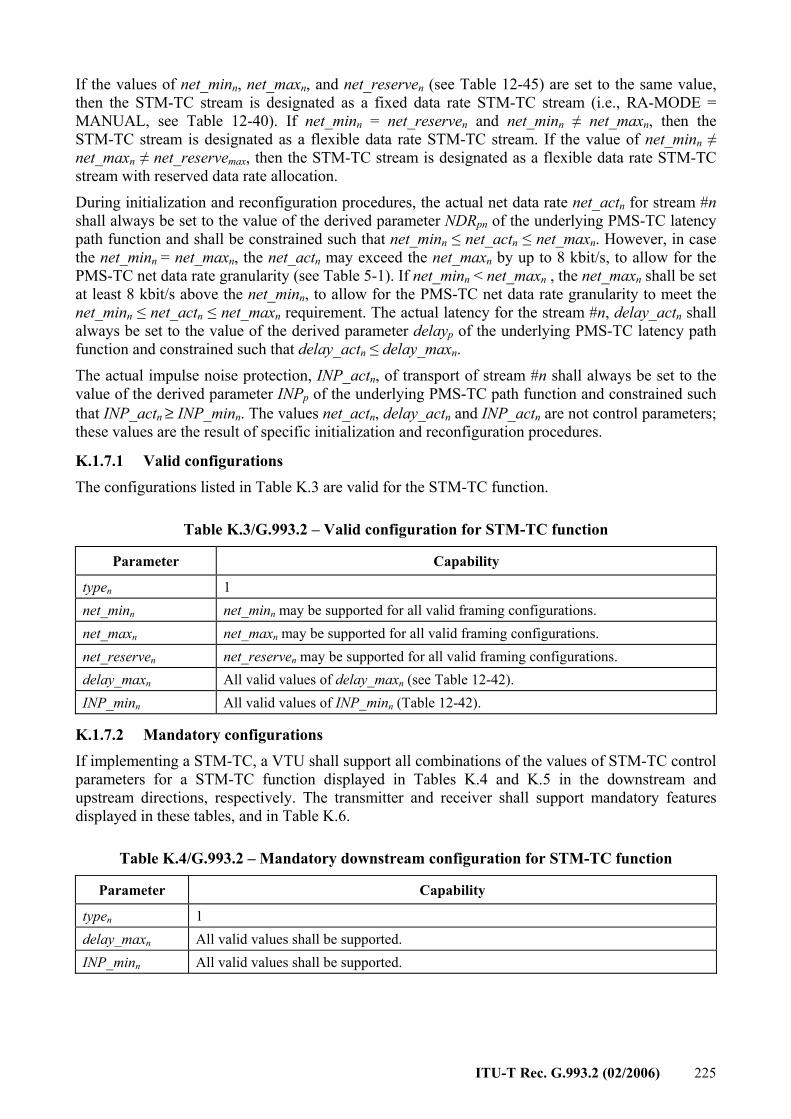


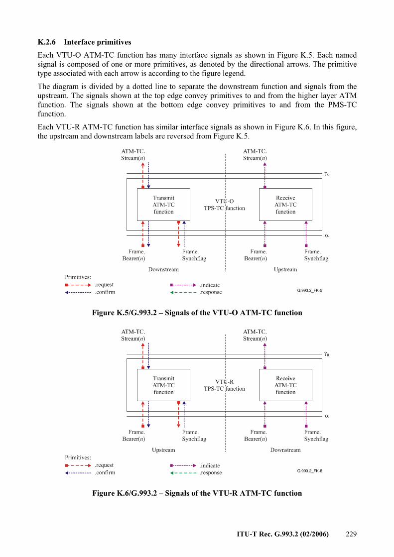


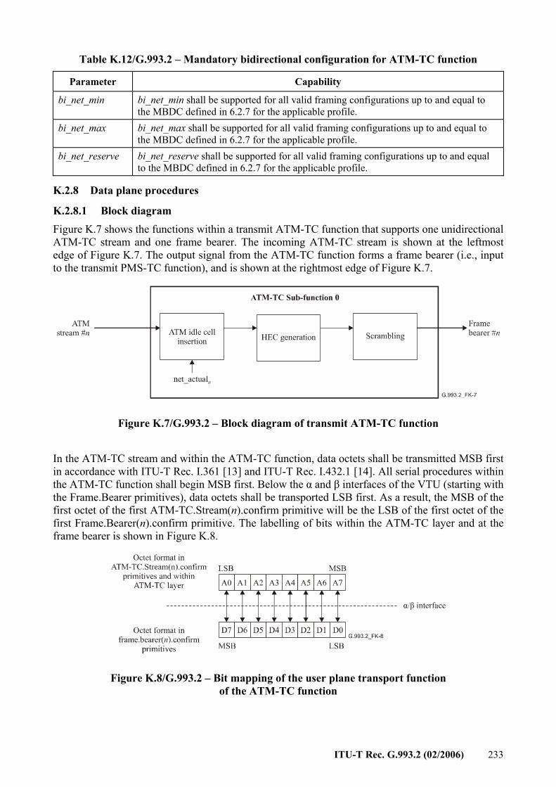
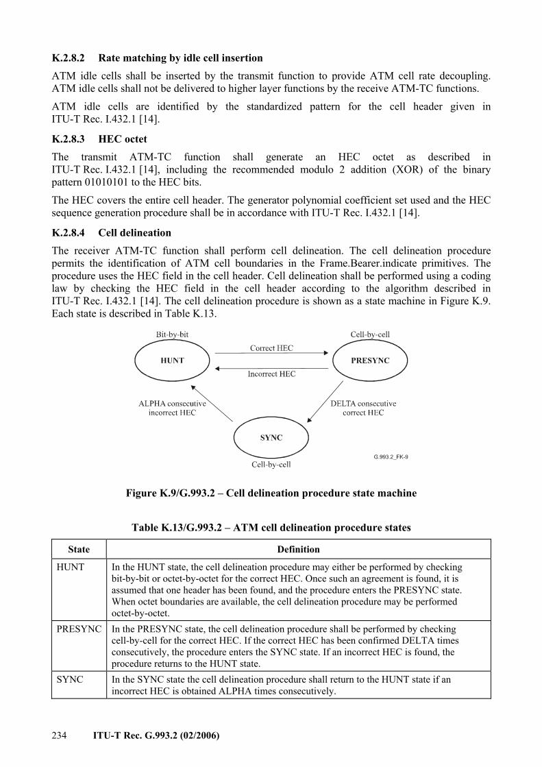

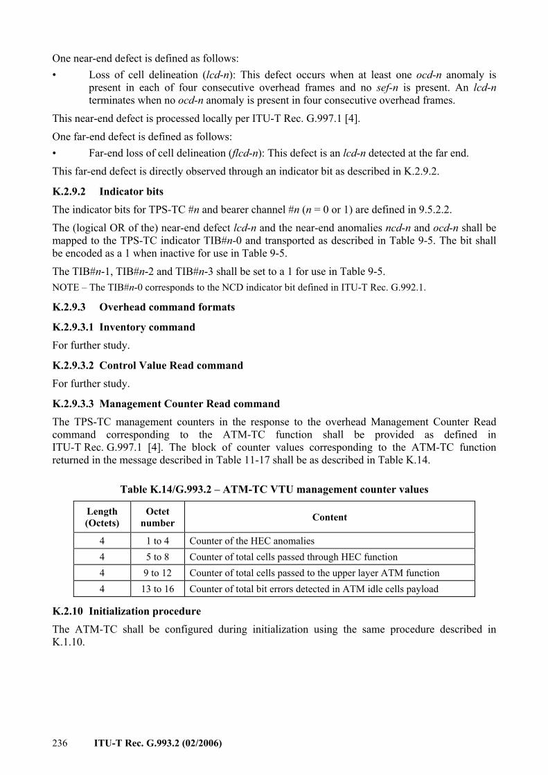


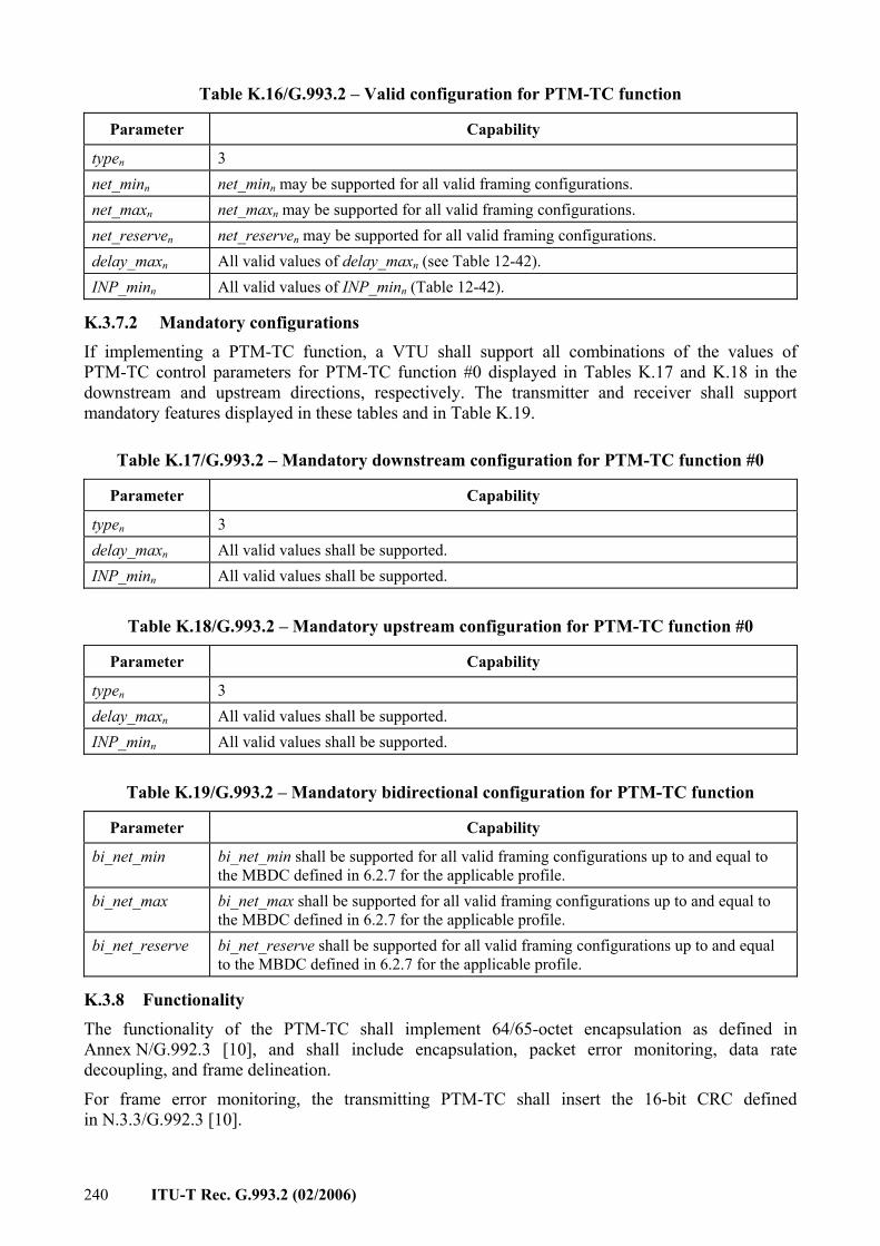


![) [Recommendation ITU-T G.993.2 modified]...ETSI 5 ETSI TS 101 271 V1.2.1 (2013-08) 1 Scope The present document provides the necessary adaptions to Recommendation ITU-T G.993.2 [1]](https://static.documents.pub/doc/80x56/5e5fedf2dbaa6e402b41497c/-recommendation-itu-t-g9932-modified-etsi-5-etsi-ts-101-271-v121-2013-08.jpg)


