The information contained in this manual iscorrect and accurate at the time of its publi-cation. Diagraph reserves the right to changeor alter any information or technical specifi-cations at any time and without notice.
Operating Temperature 40º to 110º F (4.4º to 43.3º C)
Photosensors Two with up to .75 in max. read distance
Ink Compatibility All inks are miscible, water-based, nonflammable and odorless
Ink Compliance
I.V./700 type inks contain no chemicals reportable under SARAsection 313. These inks meet CONEG legislation for printing ontopackaging components. All components of these inks are included inthe European inventory of existing chemical substances (EINECSlist).
Dimensions 3.2 in x 3.4 in x 6.4 in (81 mm x 87 mm x 164 mm)
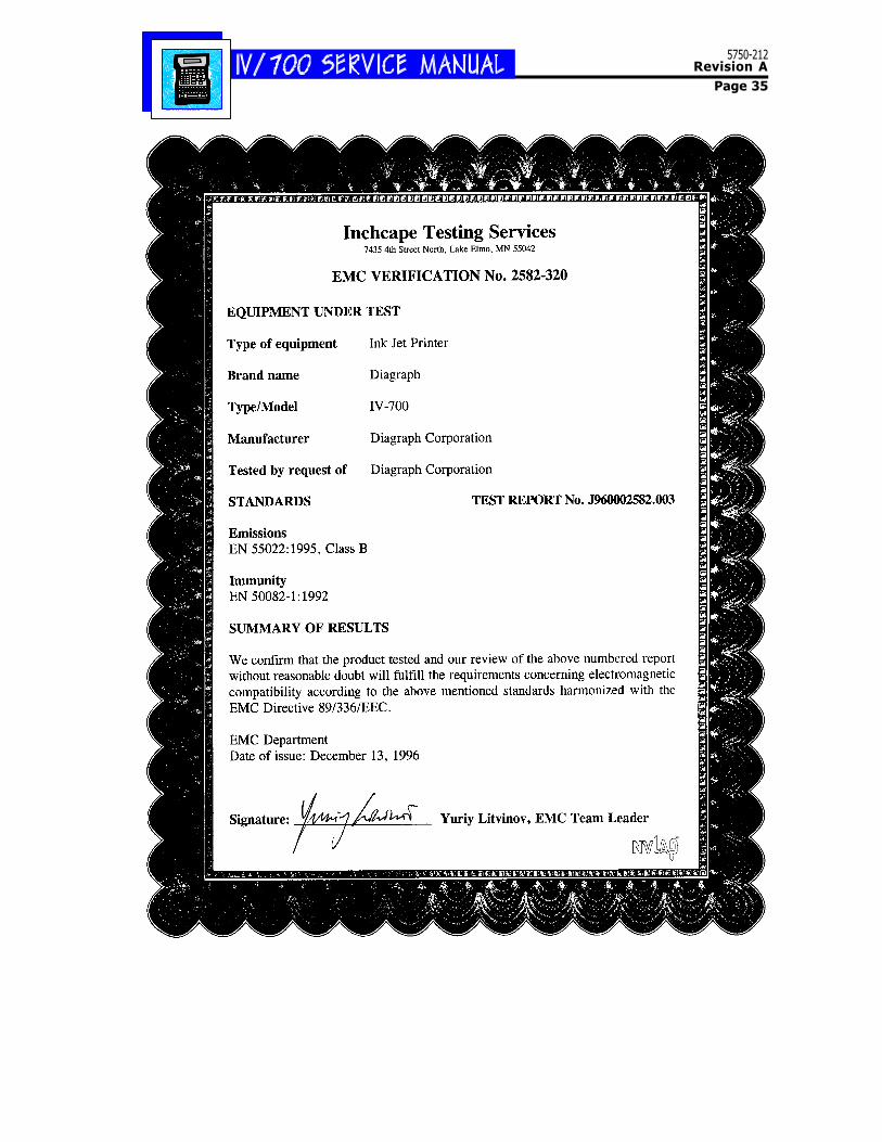
System Compliance UL / CE / CSA
Options External photosensor model available.
Printhead
Product Specifications
5750-212Revision A
Page 4
I.V./700 Components
5750-212Revision A
Page 5
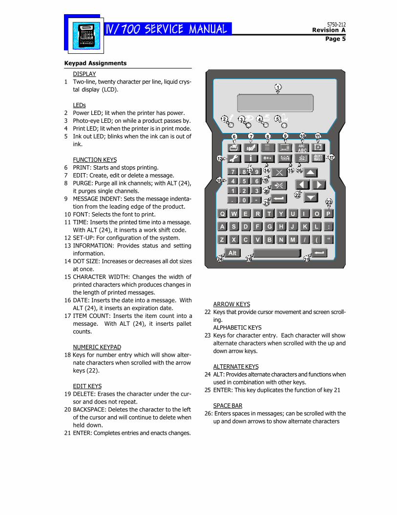
Keypad Assignments
DISPLAY1 Two-line, twenty character per line, liquid crys-
tal display (LCD).
LEDs2 Power LED; lit when the printer has power.3 Photo-eye LED; on while a product passes by.4 Print LED; lit when the printer is in print mode.5 Ink out LED; blinks when the ink can is out of
ink.
FUNCTION KEYS6 PRINT: Starts and stops printing.7 EDIT: Create, edit or delete a message.8 PURGE: Purge all ink channels; with ALT (24),
it purges single channels.9 MESSAGE INDENT: Sets the message indenta-
tion from the leading edge of the product.10 FONT: Selects the font to print.11 TIME: Inserts the printed time into a message.
With ALT (24), it inserts a work shift code.12 SET-UP: For configuration of the system.13 INFORMATION: Provides status and setting
information.14 DOT SIZE: Increases or decreases all dot sizes
at once.15 CHARACTER WIDTH: Changes the width of
printed characters which produces changes inthe length of printed messages.
16 DATE: Inserts the date into a message. WithALT (24), it inserts an expiration date.
17 ITEM COUNT: Inserts the item count into amessage. With ALT (24), it inserts palletcounts.
NUMERIC KEYPAD18 Keys for number entry which will show alter-
nate characters when scrolled with the arrowkeys (22).
EDIT KEYS19 DELETE: Erases the character under the cur-
sor and does not repeat.20 BACKSPACE: Deletes the character to the left
of the cursor and will continue to delete whenheld down.
21 ENTER: Completes entries and enacts changes.
ARROW KEYS22 Keys that provide cursor movement and screen scroll-
ing.ALPHABETIC KEYS
23 Keys for character entry. Each character will showalternate characters when scrolled with the up anddown arrow keys.
ALTERNATE KEYS24 ALT: Provides alternate characters and functions when
used in combination with other keys.25 ENTER: This key duplicates the function of key 21
SPACE BAR26: Enters spaces in messages; can be scrolled with the
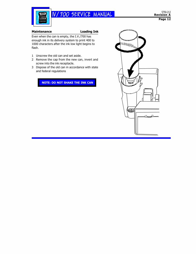
Even when the can is empty, the I.V./700 hasenough ink in its delivery system to print 400 to1000 characters after the ink low light begins toflash.
1 Unscrew the old can and set aside.2 Remove the cap from the new can, invert and
screw into the ink receptacle.3 Dispose of the old can in accordance with state
and federal regulations
NOTE: DO NOT SHAKE THE INK CAN
5750-212Revision A
Page 13
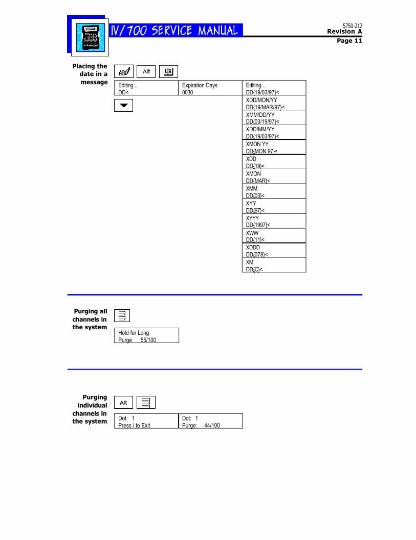
Purging All ChannelsPurge the printer at the start of the workday.
1 Hold a disposable towel in front of theprinthead.
2 Press PURGE.The printhead will expel ink for approximatelytwo seconds.Continue to press PURGE if you a want a longpurge of ink.
3 Clean the face of the printhead with water.
Hold for long purge Purge 96/100<
5750-212Revision A
Page 14
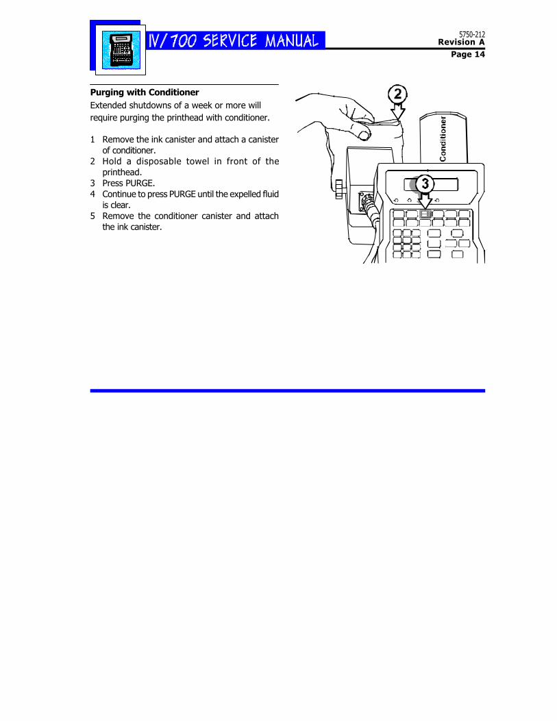
Purging with ConditionerExtended shutdowns of a week or more willrequire purging the printhead with conditioner.
1 Remove the ink canister and attach a canisterof conditioner.
2 Hold a disposable towel in front of theprinthead.
3 Press PURGE.4 Continue to press PURGE until the expelled fluid
is clear.5 Remove the conditioner canister and attach
the ink canister.
5750-212Revision A
Page 15
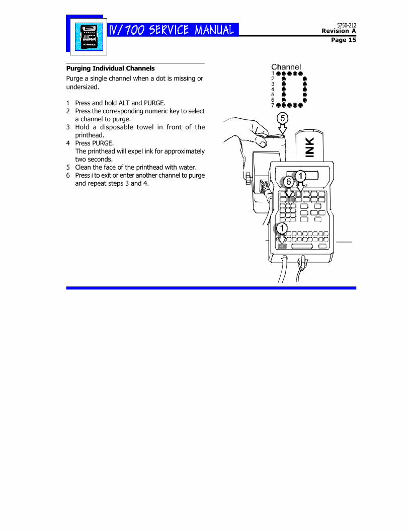
Purging Individual Channels
Purge a single channel when a dot is missing orundersized.
1 Press and hold ALT and PURGE.2 Press the corresponding numeric key to select
a channel to purge.3 Hold a disposable towel in front of the
printhead.4 Press PURGE.
The printhead will expel ink for approximatelytwo seconds.
5 Clean the face of the printhead with water.6 Press i to exit or enter another channel to purge
and repeat steps 3 and 4.
5750-212Revision A
Page 16
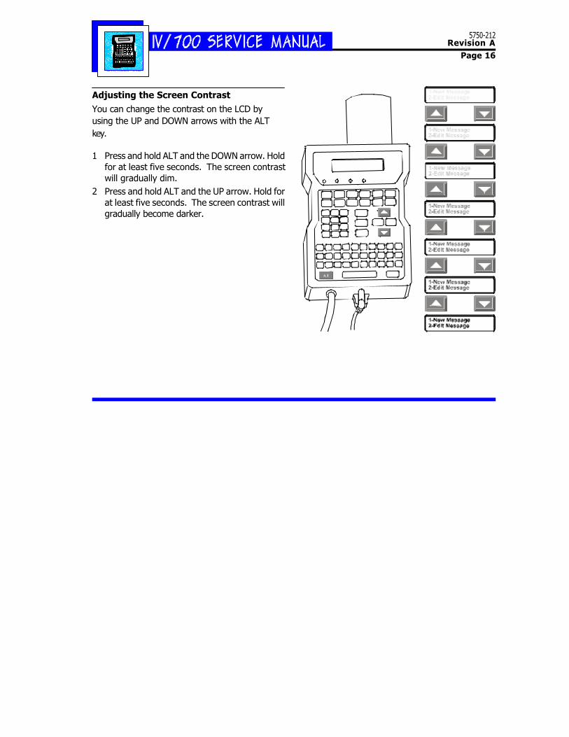
Adjusting the Screen Contrast
You can change the contrast on the LCD byusing the UP and DOWN arrows with the ALTkey.
1 Press and hold ALT and the DOWN arrow. Holdfor at least five seconds. The screen contrastwill gradually dim.
2 Press and hold ALT and the UP arrow. Hold forat least five seconds. The screen contrast willgradually become darker.
5750-212Revision A
Page 17
TroubleshootingProblems with the I.V./700 divide into threeareas: (1) the unit is not printing; (2) the unit isprinting but the results are unsatisfactory; and(3) the unit is printing but some aspect of itsoperation is unsatisfactory.
(1) Not Printing ........................................ 18(2) Unsatisfactory Print ............................. 21(3) Satisfactory Print but with Problems ...... 25Hardware Block Diagram ........................... 26Oscilloscope Plots
2 7
5750-212Revision A
Page 18
(1) Not Printing, Questions and Solu-tions
Q1 The I.V./700 is not printing and thepower LED is not lit. Why?
S1 The printer does not have power. Checkthe following:
[1] The barrel plug connection at the baseof the controller;
[2] The cable connection at the base of thepower supply;
[3] The barrel plug for a 15 VDC output;
[4] The cable connection at the rear of theprinthead;
[5] The wall receptacle to make sure that itis supplying power.
If the printer passes all the previous testsbut still will not print, then install a newcontroller board (P/N 5750-208E for Euro-pean units and 5750-208A for Asian units).
Q2 The I.V./700 is not printing, the printmode LED is on, and the photosensorLED is not blinking. Why?
S2 The photosensors can not detect the prod-uct. They can be either too far from the prod-uct or dirty. Clean the photosensors and ad-just the printhead to within 0.25 inch of theproduct.
If cleaning the photosensor and adjustingthe position of the printhead does not fix theproblem, then put a finger in front of eachphotosensor alternately and watch for thephotosensor LED to light. If a photosensoris working, then the LED will light when youtouch it. If one does not light, the driverboard must be replaced.
If neither photosensor activates LED Q2,remove the top cover of the printhead replacethe printhead driver board (P/N 5750-198).
You can use the defective unit while wait-ing for the replacement driver board by con-figuring the I.V./700 so that it operates infixed speed mode and fixed direction (see Con-troller directions below).
Setting the Print Speed
1 Press SET-UP.
2 Press E for "E-Print Speed." The LCD willprompt for a Yes or No to fixed speed print-ing.
If you select "1-No", the display will returnto the Set-Up menu. If you select "2-Yes",the LCD will ask for the speed in feet ormeters per minute.
3 Type the speed and press ENTER.
Setting the Print Direction
1 Press SET-UP.
2 Press F for "F-Print Direction." The LCDwill prompt for a Yes or No to fixed direc-tion printing.
If you select 1-No, the LCD will return tothe Set-Up menu.
3 If you select 2-Yes, the LCD will ask youto set the print direction.
4 Select a direction and press ENTER.
5750-212Revision A
Page 19
Character Width 1 Character Width 4 Character Width 6
Q3 The I.V./700 is not printing and theink LED is flashing. Why?
S3 The printer is out of ink. Replace the old inkcan with a new can. If the can is not empty,replace it anyway to eliminate the possibil-ity of a can that has lost pressure causingthe problem.
Q4 The I.V./700 is not printing but all LEDsignals are normal. Why?
S4 Address the simplest possibility first: is theI.V./700 in print mode? Carry out the op-erations described below to print a messageand verify that the printer is in print modeand can print.
If the printer is still not printing, it is pos-sible that the character width setting is toosmall for the product line speed. To rectifythis, increase the character width by follow-ing the directions below on setting the char-acter width.
1 Press PRINT and the LCD will show "1-Print"and "2-Stop Print"
2 Press 1 and the LCD will show the name ofthe last message printed and its corre-sponding text.
3 Scroll until "DIAGRAPH" appears as themessage to print appears on the LCD.
4 Press ENTER to print.5 Press 2 to stop printing.
The scanned print sample above is the de-fault DIAGRAPH message printed with con-troller default settings.
Printing a Message Changing the CharacterWidth in a Message
1 Press EDIT.
2 Press 2. Scroll until the target mes-sage is on-screen.
3 Press ENTER.
4 Press CHARACTER WIDTH.5 The LCD will show a range of 1 (nar-
row) to 9 (wide).
Select a new width by scrolling andpress ENTER.
6 Press ENTER to complete the editchange.
5750-212Revision A
Page 20
Q5 The I.V.700 is not printing even thoughall of the LED's are working normally.
S5 Remove the four Phillips screws from the con-troller housing and check the cable connec-tion between the printhead and the control-ler board. Check the continuity of the con-troller to printhead cable. If the cable is de-fective, replace it with cable 5750-192.
Q6 The I.V./700 is not printing and ALLthe LEDS are blinking. Why?
S6 A short-circuit has occurred. To determinewhether the short is in the printhead or thecontroller, disconnect the barrel plug con-nector and the printhead connector at theprinthead.
Connect the barrel plug connector but DONOT connect the printhead. If the unit ini-tializes normally, replace the printhead (P/N5750-199). If the unit does not initializenormally, replace the controller (P/N 5750-201 for a European model and 5750-202for an Asian model).
5750-212Revision A
Page 21
(2) Unsatisfactory Print
The easiest way to approach any printing problemis to reset the printer to its factory defaults andthen print the default "DIAGRAPH" message. Thissimple procedure avoids all the complications ofextreme settings that interfere with the printingprocess. After the printer successfully prints "DIA-GRAPH", then try each message that wascreated by the customer until you find the onewith parameters (font, indent or character width)that produced unsatisfactory printing.
Q7 All indications are normal but the I.V./700 prints on every other box. Why?
S7 The box length distance is longer than thelength of the product. Decrease the boxlength distance by following the directionsbelow.
Q8 The I.V./700 is printing normally but it'sthe wrong message. Why?
S8 The wrong message has been selected to print.Follow the directions below to print a mes-sage and select another message to print.
Q9 The I.V./700 is printing the correct mes-sage but the message is too far to oneside. Why?
S9 The message indent distance is incorrect. Ad-just the distance by following the directionsbelow to change an individual message in-dent and the directions to change the defaultmessage indent.
1 Press PRINT and the LCD will show "1-Print" and "2-Stop Print"
2 Press 1 and the LCD will show the nameof the last message printed and its corre-sponding text.
3 Scroll until "DIAGRAPH" appears as themessage to print appears on the LCD.
4 Press ENTER to print.
5 Press 2 to stop printing.
The scanned print sample above is thedefault DIAGRAPH message printed withcontroller default settings.
Printing a Message
Setting the Box Length1 Press SET-UP.2 Press C for “C-Box Length.” The display
will prompt for a distance.3 Type in the box length in inches or centi-
meters.
Setting the Default MessageIndent
1 Press SET-UP.
2 Press INDENT.
3 Type in an indent value.
4 Press ENTER to finish.
Setting an Individual MessageIndent
1 Press EDIT.
2 Press 2 and scroll until the target mes-sage is onscreen.
3 Press ENTER.4 Press INDENT, move the cursor to the num-
ber for change and type in a new indentvalue.
5 Press ENTER to finish.
5750-212Revision A
Page 22
Q10 The I.V./700 is printing normally butthe message is too wide. Why?
S10 The character width is too wide or too nar-row. Perform one of the following procedures:
Increase or decrease the character width byfollowing the directions below for changingthe character width.
If the unit is using the fixed speed featurethen increase or decrease the fixed speed byfollowing the directions below for changingthe fixed speed.
Q11 The I.V./700 is printing the correct mes-sage but one or more rows of ink dotsare missing from some of the charac-ters. Why?
S11 The most likely cause is some impedimenton the faceplate that is blocking ink jet ori-fices. Clean the faceplate with a wipe wet-ted with water and purge the printhead.Follow the purging instructions in the Main-tenance section.
No Noise from the Solenoid
As you conduct the individual purge proce-dure, listen for the each solenoid to make anoise. If the solenoid for the missing dot is
silent, you have a defective controllerboard, a defective driver board or a defec-tive solenoid.
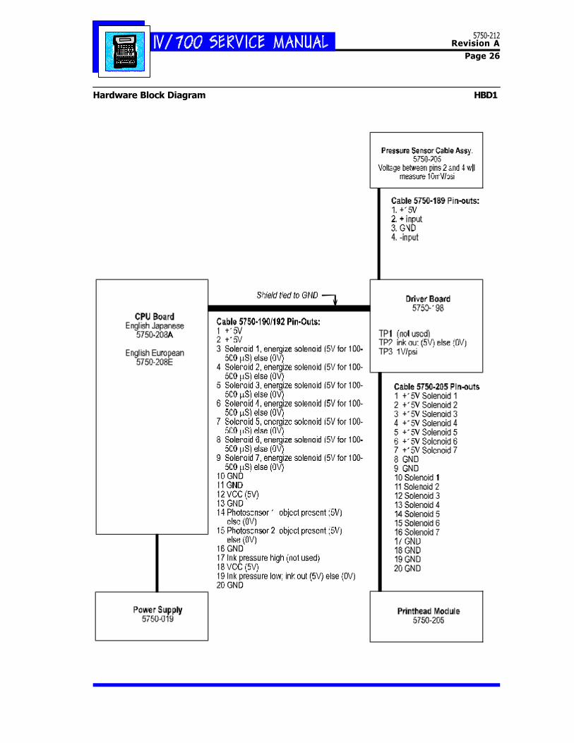
Remove the cover of the controller and thekeypad to expose the controller board.Check the controller board pins for theoutputs shown on sheet HBD1. If the out-puts do not match those shown, replacethe controller board (P/N 5750-208E forEuropean models and 5750-208A for Asianmodels).
If the controller board performs accordingto specifications, take readings on the out-puts of the printhead driver board. If theboard outputs do not match the specifica-tions shown on HBD1 and the scope plotsat the end of this section, replace the print-head driver board (P/N 5750-198).
If the driver board performs according tospecifications, the solenoid is defective.Replace the print module which containsnew solenoids (P/N 5750-205).
The solenoid is making noise but is notprinting.
If you hear the "whine" of a solenoid whilepurging individual channels but see no ink
Changing the CharacterWidth in a Message
1 Press EDIT.
2 Press 2. Scroll until the target mes-sage is on-screen.
3 Press ENTER.
4 Press CHARACTER WIDTH.
5 The LCD will show a range of 1 (nar-row) to 9 (wide).
Select a new width by scrolling andpress ENTER.
6 Press ENTER to complete the editchange.
Setting the Print Speed
1 Press SET-UP.
2 Press E for "E-Print Speed." The LCD willprompt for a Yes or No to fixed speed print-ing.
If you select "1-No", the display will returnto the Set-Up menu. If you select "2-Yes",the LCD will ask for the speed in feet ormeters per minute.
3 Type the speed and press ENTER.
5750-212Revision A
Page 23
coming from that channel, then the ink jetorifice remains blocked. Remove the obstruc-tion with a broach Kit (P/N 1902-857, shownbelow).
Q12 The I.V./700 is printing the correctmessage but all of the ink dots are toosmall. Why?
S12 The ink pressure is too low. Follow the pro-cedure in this section to adjust the regulatorand the ink flow in the printhead.
You will need a Phillips screwdriver, a multi-meter and a fresh can of ink (5750-085) forthis adjustment. Disconnect the power be-fore starting.
1. Remove the printhead cover to access testpoints on the printhead driver board.
2. Attach the black lead from the multimeterto the bare wire (pin 16, [A]) of the cableconnecting the CPU board to the driver board(see diagram below).
3. Attach the red lead of the multimeter totest point 3 (TP3, [B]) on the driver board.
4. Set the mulitmeter to DC voltage.
[A]
[B]
5. Install the new can of ink into the control-ler recepticle.
6. Power ON the I.V./700 and wait for a menuto appear.
7. Check the mulitimeter display; you shouldsee a value in the range of 5 to 8 volts DC.
8. Lift the lock ring on the regulator andslowly turn the adjustment knob counterclock-wise. The vol-tage reading should decreaseas you turn the knob.
9. Turn the knob counterclockwise until itstops and shuts off the ink flow. The multi-meter should show zero volts.
10. Place absorbent material or a containerin front of the printhead and purge until theink low lamp flashes.
11. Turn the regulator knob slowly clockwise andwatch the voltage increase on the multimeter.
12. Stop turning the knob when the multim-eter reads 7.0 volts.
13. Press the regulator locking-ring back intoplace; disconnect power and the multimeterleads; and replace the printhead cover.
[8] [13]
5750-212Revision A
Page 24
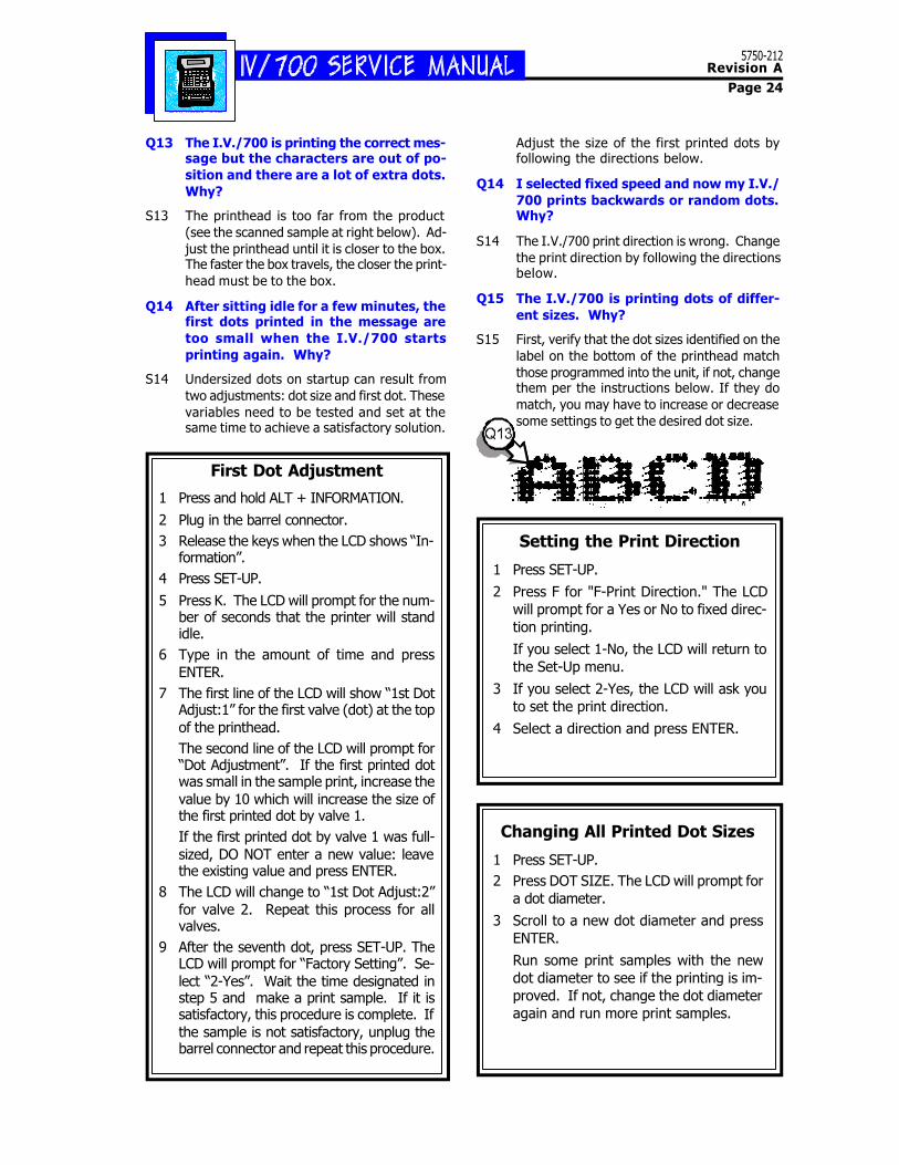
Q13 The I.V./700 is printing the correct mes-sage but the characters are out of po-sition and there are a lot of extra dots.Why?
S13 The printhead is too far from the product(see the scanned sample at right below). Ad-just the printhead until it is closer to the box.The faster the box travels, the closer the print-head must be to the box.
Q14 After sitting idle for a few minutes, thefirst dots printed in the message aretoo small when the I.V./700 startsprinting again. Why?
S14 Undersized dots on startup can result fromtwo adjustments: dot size and first dot. Thesevariables need to be tested and set at thesame time to achieve a satisfactory solution.
Adjust the size of the first printed dots byfollowing the directions below.
Q14 I selected fixed speed and now my I.V./700 prints backwards or random dots.Why?
S14 The I.V./700 print direction is wrong. Changethe print direction by following the directionsbelow.
Q15 The I.V./700 is printing dots of differ-ent sizes. Why?
S15 First, verify that the dot sizes identified on thelabel on the bottom of the printhead matchthose programmed into the unit, if not, changethem per the instructions below. If they domatch, you may have to increase or decreasesome settings to get the desired dot size.
First Dot Adjustment
1 Press and hold ALT + INFORMATION.
2 Plug in the barrel connector.3 Release the keys when the LCD shows “In-
formation”.4 Press SET-UP.
5 Press K. The LCD will prompt for the num-ber of seconds that the printer will standidle.
6 Type in the amount of time and pressENTER.
7 The first line of the LCD will show “1st DotAdjust:1” for the first valve (dot) at the topof the printhead.The second line of the LCD will prompt for“Dot Adjustment”. If the first printed dotwas small in the sample print, increase thevalue by 10 which will increase the size ofthe first printed dot by valve 1.If the first printed dot by valve 1 was full-sized, DO NOT enter a new value: leavethe existing value and press ENTER.
8 The LCD will change to “1st Dot Adjust:2”for valve 2. Repeat this process for allvalves.
9 After the seventh dot, press SET-UP. TheLCD will prompt for “Factory Setting”. Se-lect “2-Yes”. Wait the time designated instep 5 and make a print sample. If it issatisfactory, this procedure is complete. Ifthe sample is not satisfactory, unplug thebarrel connector and repeat this procedure.
Setting the Print Direction
1 Press SET-UP.
2 Press F for "F-Print Direction." The LCDwill prompt for a Yes or No to fixed direc-tion printing.
If you select 1-No, the LCD will return tothe Set-Up menu.
3 If you select 2-Yes, the LCD will ask youto set the print direction.
4 Select a direction and press ENTER.
Changing All Printed Dot Sizes
1 Press SET-UP.2 Press DOT SIZE. The LCD will prompt for
a dot diameter.
3 Scroll to a new dot diameter and pressENTER.
Run some print samples with the newdot diameter to see if the printing is im-proved. If not, change the dot diameteragain and run more print samples.
5750-212Revision A
Page 25
(3) Satisfactory Print with Other Problems
This section covers problems that do not cause theprinter to stop printing nor produce unsatisfactoryprints. These situations are warnings that moreserious problems might be on the way.Q15 Shouldn't I shake the ink can before I
install it in the printer? I always haveto shake paint cans.
S15 No. Never shake a can of Diagraph ink. The inkin the can is actually in a bag that is attached tothe fitting at the top of the can. The can hasbeen pressurized with air that pushes against thesides of the bag and forces ink through the fit-ting. If vigorously shaken, the bag can tear looseand ink will not flow from the can.
Q16 Do I need to cover my I.V./700 printerduring a washdown?
S16 Yes.
Q17 I've noticed ink accumulating on thefaceplate. Is this normal?
S17 Yes. Over the course of an 8-hour shift enoughink may accumulate to form a hanging drop.This ink may allow environmental debris toaccumulate, which is why the frontplateshould be wiped after at the beginning andend of each shift.
Q18 I'm running the I.V./700 eight hours perday and have to replace the ink can ev-ery other day. Is this normal?
S18 Perhaps. Each can of ink will print approxi-mately 225,000 characters. Actual usage var-ies depending upon operating conditions.
Q19 I see ink in the receptacle for the ink canwhen I install a new can. Is this normal?
S19 Yes. A few drops of ink may accumulate eachtime the ink can is changed, eventually build-ing up if not cleaned away.
Q20 Ink is leaking from the fitting where theink line attaches to the controller. Whatshould I do?
S20 Replace the lower enclosure assembly of thecontroller (P/N 5750-207).
Q21 Ink is leaking from the fitting on the pig-tail from the printhead? Is this normal?
S21 No. Replace the fittings. Use P/N 5750-214for the female and 5750-213 for the male.
Q22 What parts should I expect to replaceafter a year of 8-hour-per-day usage?
S22 None in a normal environment. Generally, thefirst thing to fail is the printhead, which lastsover a year.
5750-212Revision A
Page 26
Hardware Block Diagram HBD1
5750-212Revision A
Page 27
Oscilloscope Plot of Driver Board 15 V OutputVeritcal Setting: 5.0 VDC per divisionHorizontal Setting: 50 microseconds per division
5750-212Revision A
Page 28
Oscilloscope Plot of CPU Board 5 V OutputVeritcal Setting: 2.0 VDC per divisionHorizontal Setting: 50 microseconds per division
tal (4.8 dots/cm)Dot Diameter Range: 0.100 inch to 0.125 inch
(2.54 mm to 3.175 mm)Recommended Throw Distance: 0.25 in. max
(6.35mm)Max. Line Speed: 250 ft/min (76.2 m/min)Photosensors:Two photosensors to measure speed
and direction.Operating Pressure: 7psig-9 psigCharacter Height: .50 in (12.7 mm) 7-dot font
.36 in. (9 mm) 5-dot font
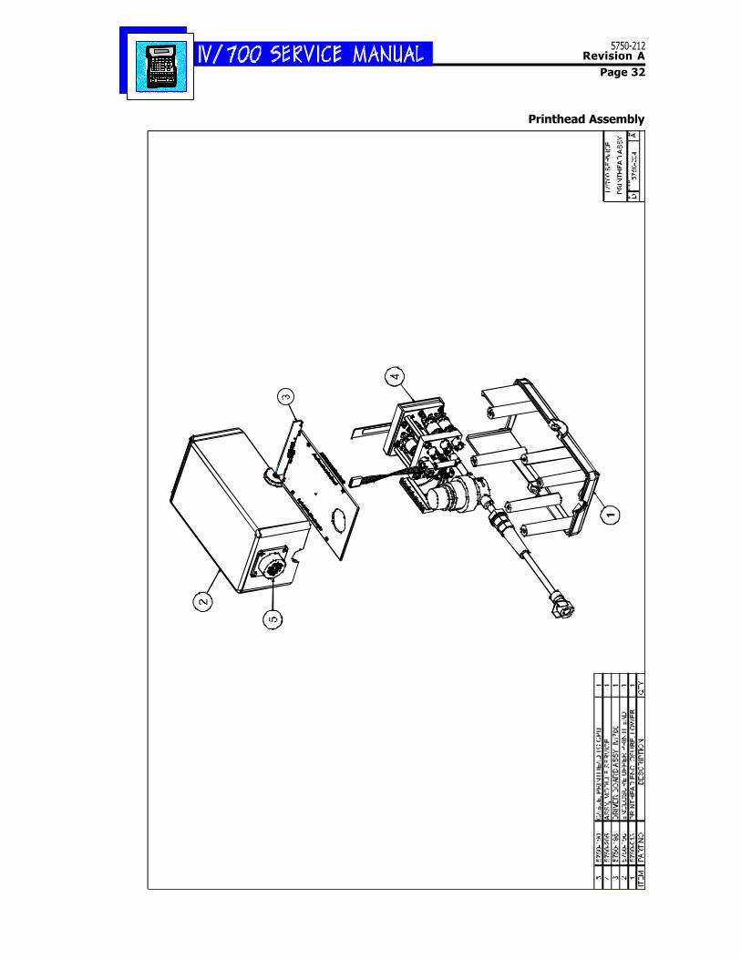
Printhead InstallationBefore starting the installation, note the label onthe bottom of the printhead. This label showsthe optimal adjustments for printhead variables atthe time of manufacture. Each printhead isunique and requires individual adjustments foroptimal printing. Copy these values so you canenter them into the controller. At right is anexample of the label. DO NOT USE THE VALUESIN THIS SAMPLE LABEL. Use the values on thelabel on your printhead.
1 Secure the printhead in its bracket with the four-prong knobs at [A].
2 Connect the ink line from the I.V./700 control-ler to the ink fitting at [B].
3 Connect the signal cable from the I.V./700 con-troller to the printhead at [C].
4 Insert the ink can and power up the controller.
5 Place a clean wipe against the faceplate and pressPURGE.
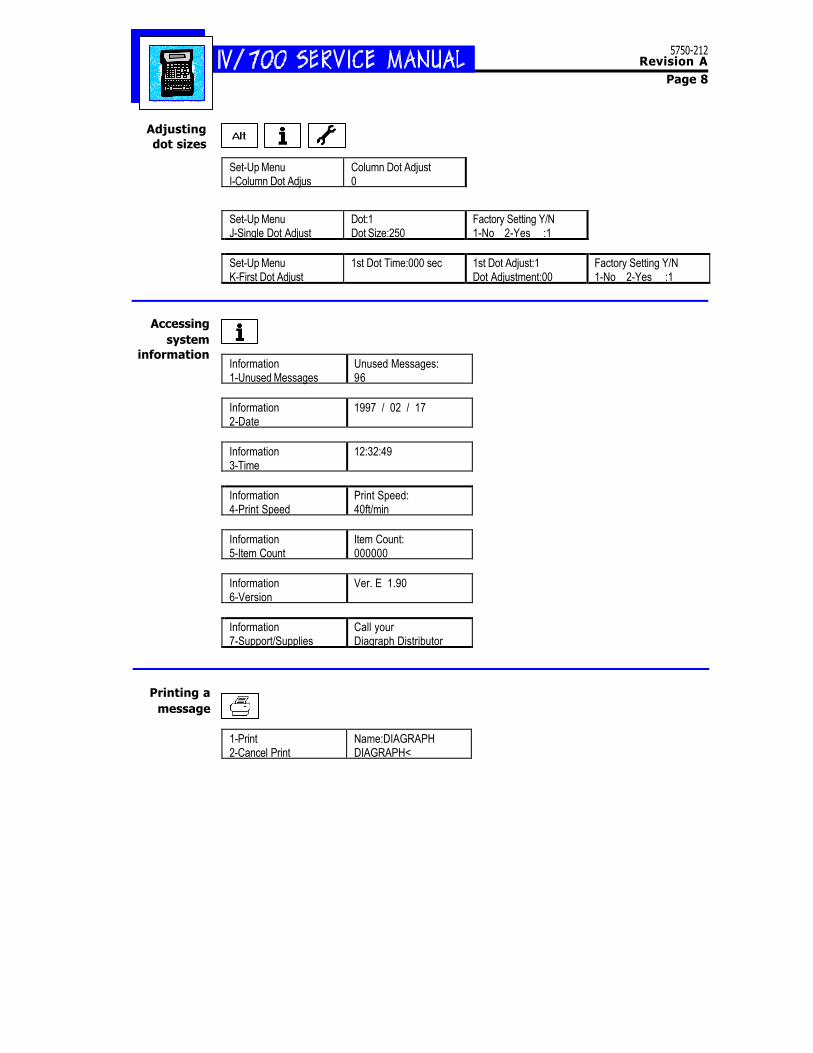
Printhead Settings1 Simultaneously press ALT and INFORMATION and
plug in the barrel connector. Release the keyswhen the display shows the information menu.
2 Press SET-UP. The LCD will show the extendedmenu with additional choices.
3 Press I and the LCD will show "Column Dot Ad-just:" Press ENTER.
5750-212Revision A
Page 38
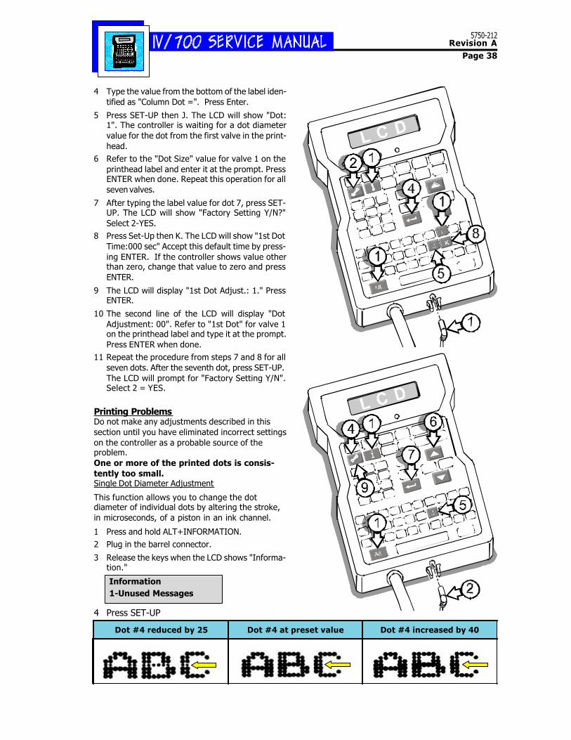
4 Type the value from the bottom of the label iden-tified as "Column Dot =". Press Enter.
5 Press SET-UP then J. The LCD will show "Dot:1". The controller is waiting for a dot diametervalue for the dot from the first valve in the print-head.
6 Refer to the "Dot Size" value for valve 1 on theprinthead label and enter it at the prompt. PressENTER when done. Repeat this operation for allseven valves.
7 After typing the label value for dot 7, press SET-UP. The LCD will show "Factory Setting Y/N?"Select 2-YES.
8 Press Set-Up then K. The LCD will show "1st DotTime:000 sec" Accept this default time by press-ing ENTER. If the controller shows value otherthan zero, change that value to zero and pressENTER.
9 The LCD will display "1st Dot Adjust.: 1." PressENTER.
10 The second line of the LCD will display "DotAdjustment: 00". Refer to "1st Dot" for valve 1on the printhead label and type it at the prompt.Press ENTER when done.
11 Repeat the procedure from steps 7 and 8 for allseven dots. After the seventh dot, press SET-UP.The LCD will prompt for "Factory Setting Y/N".Select 2 = YES.
Printing ProblemsDo not make any adjustments described in thissection until you have eliminated incorrect settingson the controller as a probable source of theproblem.One or more of the printed dots is consis-tently too small.Single Dot Diameter Adjustment
This function allows you to change the dotdiameter of individual dots by altering the stroke,in microseconds, of a piston in an ink channel.
1 Press and hold ALT+INFORMATION.2 Plug in the barrel connector.
3 Release the keys when the LCD shows "Informa-tion."
4 Press SET-UP
Information1-Unused Messages
Dot #4 reduced by 25 Dot #4 at preset value Dot #4 increased by 40
5750-212Revision A
Page 39
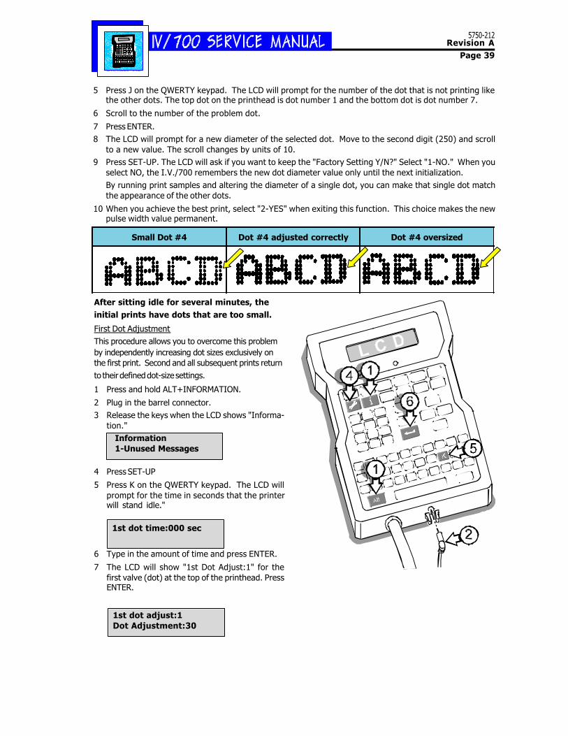
5 Press J on the QWERTY keypad. The LCD will prompt for the number of the dot that is not printing likethe other dots. The top dot on the printhead is dot number 1 and the bottom dot is dot number 7.
6 Scroll to the number of the problem dot.
7 Press ENTER.8 The LCD will prompt for a new diameter of the selected dot. Move to the second digit (250) and scroll
to a new value. The scroll changes by units of 10.9 Press SET-UP. The LCD will ask if you want to keep the "Factory Setting Y/N?" Select "1-NO." When you
select NO, the I.V./700 remembers the new dot diameter value only until the next initialization.By running print samples and altering the diameter of a single dot, you can make that single dot matchthe appearance of the other dots.
10 When you achieve the best print, select "2-YES" when exiting this function. This choice makes the newpulse width value permanent.
Small Dot #4 Dot #4 adjusted correctly Dot #4 oversized
After sitting idle for several minutes, theinitial prints have dots that are too small.
First Dot AdjustmentThis procedure allows you to overcome this problemby independently increasing dot sizes exclusively onthe first print. Second and all subsequent prints returnto their defined dot-size settings.
1 Press and hold ALT+INFORMATION.
2 Plug in the barrel connector.3 Release the keys when the LCD shows "Informa-
tion." Information 1-Unused Messages
4 Press SET-UP
5 Press K on the QWERTY keypad. The LCD willprompt for the time in seconds that the printerwill stand idle."
1st dot time:000 sec
6 Type in the amount of time and press ENTER.
7 The LCD will show "1st Dot Adjust:1" for thefirst valve (dot) at the top of the printhead. PressENTER.
1st dot adjust:1 Dot Adjustment:30
5750-212Revision A
Page 40
The second line of the LCD will prompt for "Dot Adjustment." If this dot is small in the sample print (seethe first sample below), increase the value by 10 which increases the size of the dot for the first print.
If the dot was full-size, DO NOT enter a new value: leave the existing value and press ENTER
8 The display will change to "1st Dot Adjust:2" for the second valve. Press ENTER and the second line willprompt for "Dot Adjustment." Repeat this process through all seven dots.
9 After the seventh dot, press SET-UP. The LCD will prompt for "Factory Setting." Select "2-YES."Wait the time designated in step 5, then print a message. If the print is satisfactory, unplug and replug toset the I.V./700 in print mode. If the print is unsatisfactory reset the first dot by repeating this procedure(C8) and run another sample. Repeat until you achieve a satisfactory first print.
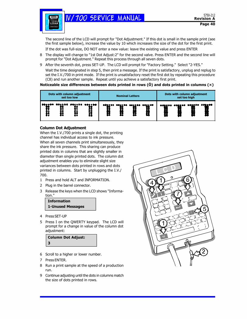
Noticeable size differences between dots printed in rows (Ö) and dots printed in columns (×)
Dots with column adjustmentset too low Nominal Letters
Dots with column adjustmentset too high
Column Dot AdjustmentWhen the I.V./700 prints a single dot, the printingchannel has individual access to ink pressure.When all seven channels print simultaneously, theyshare the ink pressure. This sharing can produceprinted dots in columns that are slightly smaller indiameter than single printed dots. The column dotadjustment enables you to eliminate slight sizevariances between dots printed in rows and dotsprinted in columns. Start by unplugging the I.V./700.1 Press and hold ALT and INFORMATION.2 Plug in the barrel connector.
3 Release the keys when the LCD shows "Informa-tion."
Information 1-Unused Messages
4 Press SET-UP
5 Press I on the QWERTY keypad. The LCD willprompt for a change in value of the column dotadjustment:
Column Dot Adjust:
3
6 Scroll to a higher or lower number.
7 Press ENTER.8 Run a print sample at the speed of a production
run.9 Continue adjusting until the dots in columns match
the size of dots printed in rows.
5750-212Revision A
Page 41
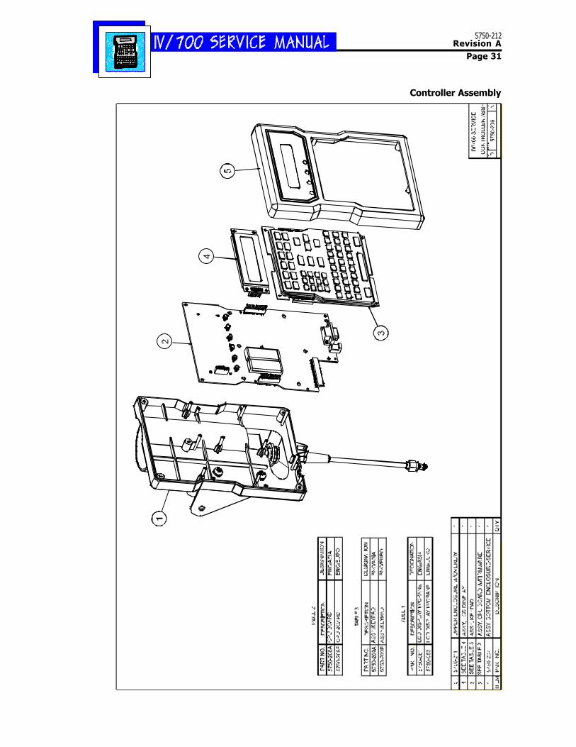
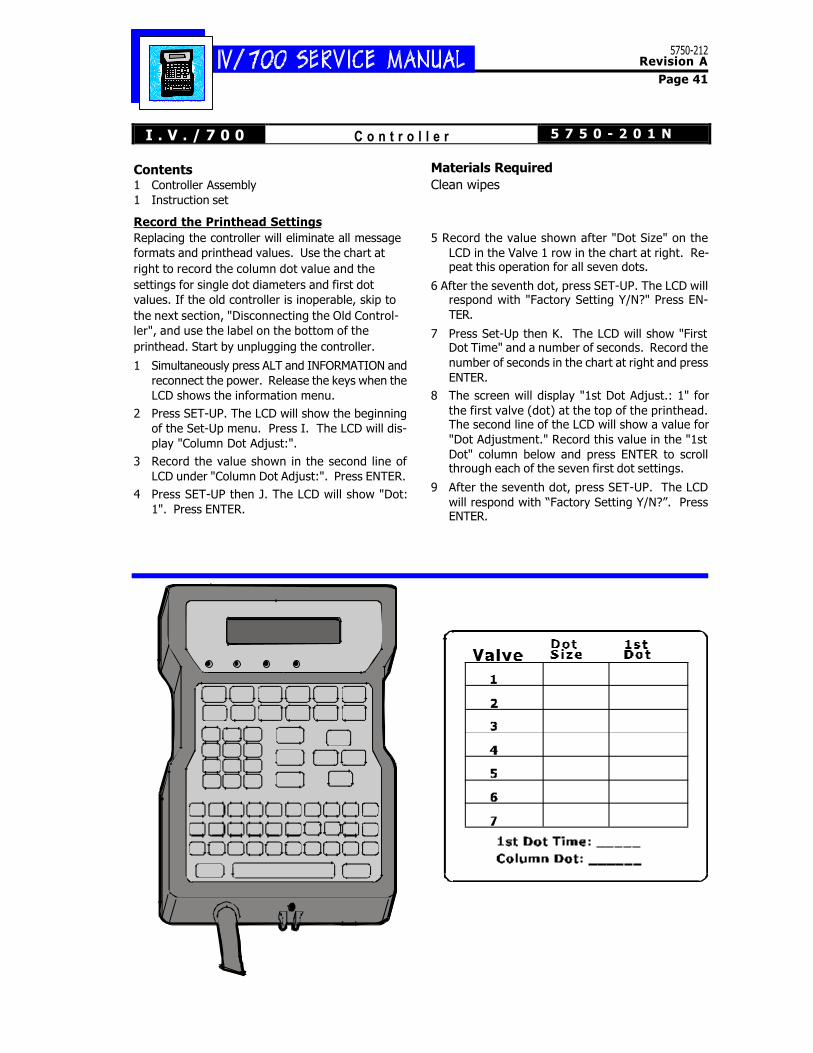
Contents1 Controller Assembly1 Instruction set
Record the Printhead SettingsReplacing the controller will eliminate all messageformats and printhead values. Use the chart atright to record the column dot value and thesettings for single dot diameters and first dotvalues. If the old controller is inoperable, skip tothe next section, "Disconnecting the Old Control-ler", and use the label on the bottom of theprinthead. Start by unplugging the controller.
1 Simultaneously press ALT and INFORMATION andreconnect the power. Release the keys when theLCD shows the information menu.
2 Press SET-UP. The LCD will show the beginningof the Set-Up menu. Press I. The LCD will dis-play "Column Dot Adjust:".
3 Record the value shown in the second line ofLCD under "Column Dot Adjust:". Press ENTER.
4 Press SET-UP then J. The LCD will show "Dot:1". Press ENTER.
Materials RequiredClean wipes
5 Record the value shown after "Dot Size" on theLCD in the Valve 1 row in the chart at right. Re-peat this operation for all seven dots.
6 After the seventh dot, press SET-UP. The LCD willrespond with "Factory Setting Y/N?" Press EN-TER.
7 Press Set-Up then K. The LCD will show "FirstDot Time" and a number of seconds. Record thenumber of seconds in the chart at right and pressENTER.
8 The screen will display "1st Dot Adjust.: 1" forthe first valve (dot) at the top of the printhead.The second line of the LCD will show a value for"Dot Adjustment." Record this value in the "1stDot" column below and press ENTER to scrollthrough each of the seven first dot settings.
9 After the seventh dot, press SET-UP. The LCDwill respond with “Factory Setting Y/N?”. PressENTER.
I . V . / 7 0 0 C o n t r o l l e r 5 7 5 0 - 2 0 1 N
5750-212Revision A
Page 42
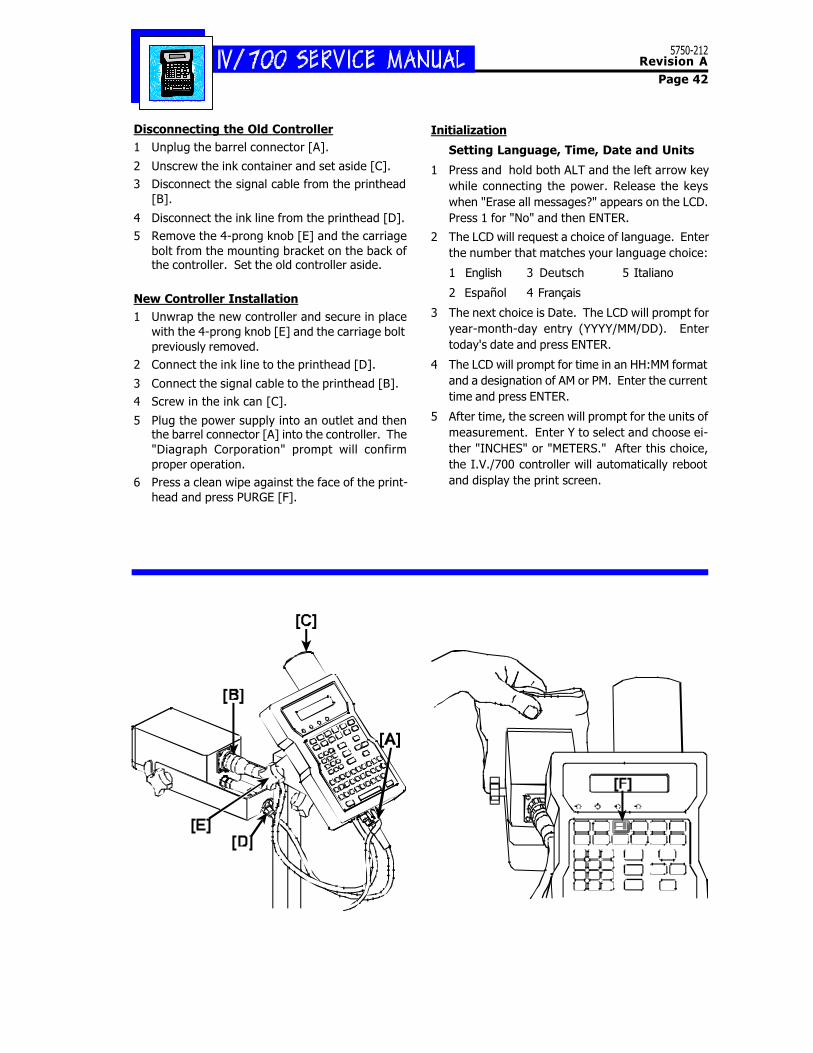
Disconnecting the Old Controller1 Unplug the barrel connector [A].
2 Unscrew the ink container and set aside [C].3 Disconnect the signal cable from the printhead
[B].
4 Disconnect the ink line from the printhead [D].5 Remove the 4-prong knob [E] and the carriage
bolt from the mounting bracket on the back ofthe controller. Set the old controller aside.
New Controller Installation1 Unwrap the new controller and secure in place
with the 4-prong knob [E] and the carriage boltpreviously removed.
2 Connect the ink line to the printhead [D].
3 Connect the signal cable to the printhead [B].4 Screw in the ink can [C].
5 Plug the power supply into an outlet and thenthe barrel connector [A] into the controller. The"Diagraph Corporation" prompt will confirmproper operation.
6 Press a clean wipe against the face of the print-head and press PURGE [F].
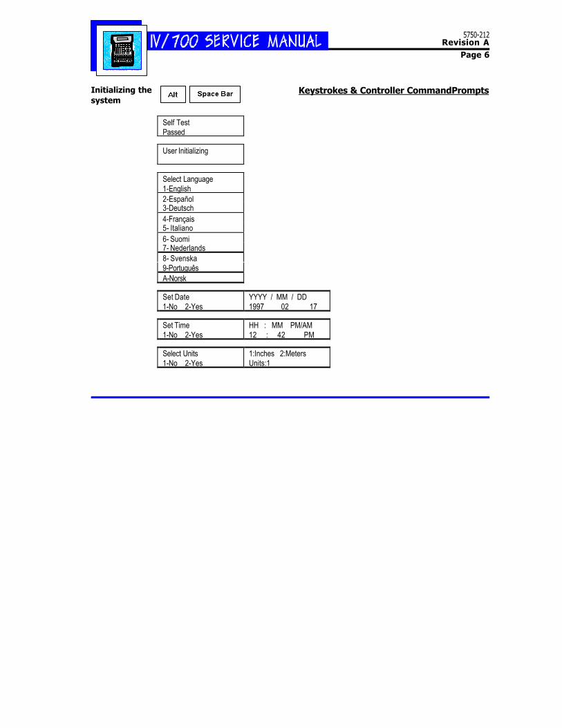
Initialization
Setting Language, Time, Date and Units
1 Press and hold both ALT and the left arrow keywhile connecting the power. Release the keyswhen "Erase all messages?" appears on the LCD.Press 1 for "No" and then ENTER.
2 The LCD will request a choice of language. Enterthe number that matches your language choice:
1 English 3 Deutsch 5 Italiano
2 Español 4 Français
3 The next choice is Date. The LCD will prompt foryear-month-day entry (YYYY/MM/DD). Entertoday's date and press ENTER.
4 The LCD will prompt for time in an HH:MM formatand a designation of AM or PM. Enter the currenttime and press ENTER.
5 After time, the screen will prompt for the units ofmeasurement. Enter Y to select and choose ei-ther "INCHES" or "METERS." After this choice,the I.V./700 controller will automatically rebootand display the print screen.
5750-212Revision A
Page 43
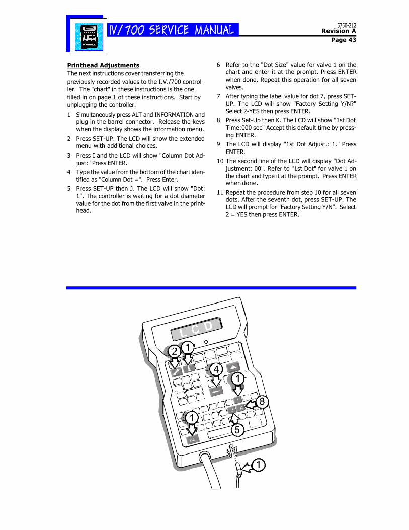
Printhead AdjustmentsThe next instructions cover transferring thepreviously recorded values to the I.V./700 control-ler. The "chart" in these instructions is the onefilled in on page 1 of these instructions. Start byunplugging the controller.
1 Simultaneously press ALT and INFORMATION andplug in the barrel connector. Release the keyswhen the display shows the information menu.
2 Press SET-UP. The LCD will show the extendedmenu with additional choices.
3 Press I and the LCD will show "Column Dot Ad-just:" Press ENTER.
4 Type the value from the bottom of the chart iden-tified as "Column Dot =". Press Enter.
5 Press SET-UP then J. The LCD will show "Dot:1". The controller is waiting for a dot diametervalue for the dot from the first valve in the print-head.
6 Refer to the "Dot Size" value for valve 1 on thechart and enter it at the prompt. Press ENTERwhen done. Repeat this operation for all sevenvalves.
7 After typing the label value for dot 7, press SET-UP. The LCD will show "Factory Setting Y/N?"Select 2-YES then press ENTER.
8 Press Set-Up then K. The LCD will show "1st DotTime:000 sec" Accept this default time by press-ing ENTER.
9 The LCD will display "1st Dot Adjust.: 1." PressENTER.
10 The second line of the LCD will display "Dot Ad-justment: 00". Refer to "1st Dot" for valve 1 onthe chart and type it at the prompt. Press ENTERwhen done.
11 Repeat the procedure from step 10 for all sevendots. After the seventh dot, press SET-UP. TheLCD will prompt for "Factory Setting Y/N". Select2 = YES then press ENTER.
5750-212Revision A
Page 44
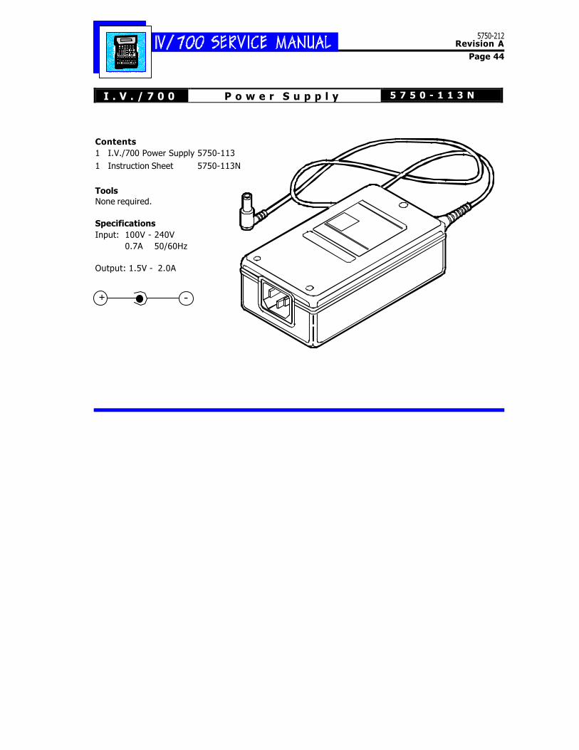
I . V . / 7 0 0 P o w e r S u p p l y 5 7 5 0 - 1 1 3 N
Contents1 I.V./700 Power Supply 5750-1131 Instruction Sheet 5750-113N
ToolsNone required.
SpecificationsInput: 100V - 240V
0.7A 50/60Hz
Output: 1.5V - 2.0A
+ -
5750-212Revision A
Page 45
I . V . / 7 0 0 T u b i n g K i t 5 7 5 0 - 1 2 5 N
Typical InstallationThis tubing kit enables you to replace a damagedink line segment between an I.V./700 controllerand an I.V./700 printhead. The illustration aboveshows a typical installation.
Installation Notes_Unscrew the ink can from the controller and setaside before starting the ink line replacement._Before cutting away damaged tubing, depress thenipple end of the original male quick-disconnectfitting to bleed ink from the tubing. Warning: This ink pressure can be up to90 PSIG (6.2 Bar). Exercise Caution!_Wrap a clean wipe around the original ink linebefore cutting to absorb spilled ink._Use a sharp blade such as a single-sided razorblade, utility knife or diagonal side cutters to makea clean cut in the replacement tubing. Avoidcrimping the tubing when cutting._Loosen the nut on the fitting. Slip the tubingover the barbed end of the fitting. Tighten the nutuntil it comes to a stop._Exercise caution when pressurizing the tubing forthe first time.
[A] Original ink line.
[B] Replacement female quick-disconnect fitting.
[C] Replacement male quick-disconnect fitting.
[D] Replacement ink line cut to desired lengthfrom the 24 inches of tubing provided inthis kit.
[B] [C]
[C]
[D]
5750-212Revision A
Page 46
WARNING: ESD SENSITIVE DEVICE. OBSERVE PRECAUTIONS.Use anti-static protection throughout these procedures. Follow the directions included withdisposable wrist strap.
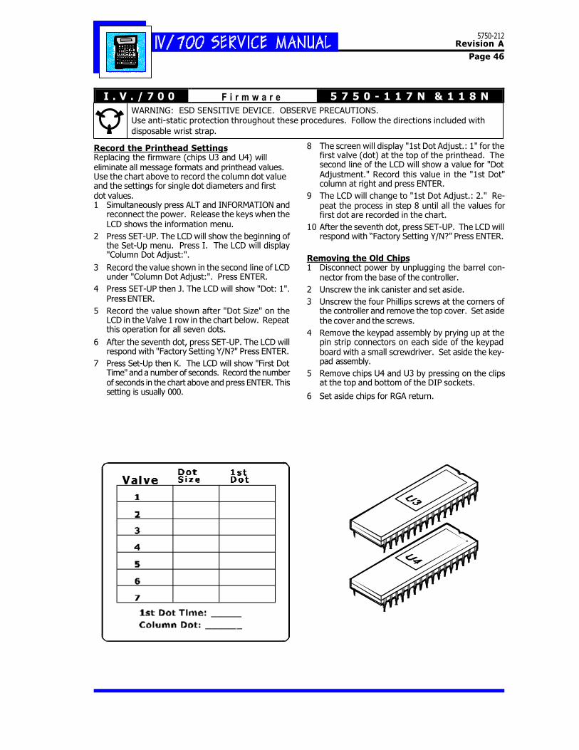
Record the Printhead SettingsReplacing the firmware (chips U3 and U4) willeliminate all message formats and printhead values.Use the chart above to record the column dot valueand the settings for single dot diameters and firstdot values.1 Simultaneously press ALT and INFORMATION and
reconnect the power. Release the keys when theLCD shows the information menu.
2 Press SET-UP. The LCD will show the beginning ofthe Set-Up menu. Press I. The LCD will display"Column Dot Adjust:".
3 Record the value shown in the second line of LCDunder "Column Dot Adjust:". Press ENTER.
4 Press SET-UP then J. The LCD will show "Dot: 1".Press ENTER.
5 Record the value shown after "Dot Size" on theLCD in the Valve 1 row in the chart below. Repeatthis operation for all seven dots.
6 After the seventh dot, press SET-UP. The LCD willrespond with "Factory Setting Y/N?" Press ENTER.
7 Press Set-Up then K. The LCD will show "First DotTime" and a number of seconds. Record the numberof seconds in the chart above and press ENTER. Thissetting is usually 000.
8 The screen will display "1st Dot Adjust.: 1" for thefirst valve (dot) at the top of the printhead. Thesecond line of the LCD will show a value for "DotAdjustment." Record this value in the "1st Dot"column at right and press ENTER.
9 The LCD will change to "1st Dot Adjust.: 2." Re-peat the process in step 8 until all the values forfirst dot are recorded in the chart.
10 After the seventh dot, press SET-UP. The LCD willrespond with “Factory Setting Y/N?” Press ENTER.
Removing the Old Chips1 Disconnect power by unplugging the barrel con-
nector from the base of the controller.2 Unscrew the ink canister and set aside.3 Unscrew the four Phillips screws at the corners of
the controller and remove the top cover. Set asidethe cover and the screws.
4 Remove the keypad assembly by prying up at thepin strip connectors on each side of the keypadboard with a small screwdriver. Set aside the key-pad assembly.
5 Remove chips U4 and U3 by pressing on the clipsat the top and bottom of the DIP sockets.
6 Set aside chips for RGA return.
I . V . / 7 0 0 F i r m w a r e 5 7 5 0 - 1 1 7 N & 1 1 8 N
5750-212Revision A
Page 47
Installing the New Chips1 Remove the chip set from the foam packing and
match labels of "U3" and "U4" with the chip sock-ets on the controller board.
2 Orient chips with the notches at the top-towardsthe LCD screen. Ensure that no pins are bent.
3 Carefully align pins and firmly push each chipinto its socket. DIP socket clips will snap intoplace when the chips are seated correctly.
4 Replace the keypad assembly by matching andpressing into place the pin strip connectors oneach side of the keypad board.
5 Replace the top cover and secure in place withthe four Phillips screws removed earlier.
Initialization
Setting Language, Time, Date and Units
The first time you plug in the I.V./700 with newfirmware, you must select the language, time, dateand unit of measure.1 Plug in the barrel connector.
2 The LCD will request a choice of language. En-ter the number that matches your languagechoice:1 English 3 Deutsch 5 Italiano
2 Español 4 Français
3 The next choice is Date. The LCD will prompt foryear-month-day entry (YYYY/MM/DD). Entertoday's date and press ENTER.
4 The LCD will prompt for time in an HH:MM for-mat and a designation of AM or PM. Enter thecurrent time and press ENTER.
5 After time, the LCD will prompt for the units ofmeasurement. Enter Y to select and choose ei-ther "INCHES" or "METERS." After this choice,the I.V./700 controller will change to the printmessage screen.
Printhead Adjustments
The next instructions cover transferring thepreviously recorded values to the I.V./700 control-ler. The "chart" in these instructions is the onefilled in on page 1 of these instructions. Start byunplugging the controller.
1 Simultaneously press ALT and INFORMATION andplug in the barrel connector. Release the keyswhen the display shows the information menu.
2 Press SET-UP. The LCD will show the extendedmenu with additional choices.
3 Press I and the LCD will show "Column Dot Ad-just:" Press ENTER.
4 Type the value from the bottom of the chart iden-tified as "Column Dot =". Press Enter.
5 Press SET-UP then J. The LCD will show "Dot: 1".The controller is waiting for a dot diameter valuefor the dot from the first valve in the printhead.
6 Refer to the "Dot Size" value for valve 1 on thechart and enter it at the prompt. Press ENTERwhen done. Repeat this operation for all sevenvalves.
7 After typing the label value for dot 7, press SET-UP. The LCD will show "Factory Setting Y/N?"Select 2-YES.
8 Press Set-Up then K. The LCD will show "1st DotTime:000 sec" Accept this default time by press-ing ENTER.
9 The LCD will display "1st Dot Adjust.: 1."10 The second line of the LCD will display "Dot Ad-
justment: 00". Refer to "1st Dot" for valve 1 onthe chart and type it at the prompt. Press ENTERwhen done.
11 Repeat the procedure from step 10 for all sevendots. After the seventh dot, press SET-UP. TheLCD will prompt for "Factory Setting Y/N". Select2 = YES.
5750-212Revision A
Page 48
I.V./700 External Photosensor 5750-183NThese instructions cover the configurationof the I.V./700 ink jet printer with theexternal photosensor.
ContentsExternal Photosensor [1] and bracket [2]5750-113Photosensor/Controller Cable [3]5750-182Instruction Sheet5750-183N
Configuration
See the diagram on page 2 for theconfiguration command sequence. Note dimension "X" in the illustration atright--the distance from the center of thephotosensor to the center of the printhead.When mounting the photosensor, makesure that the X dimension is less than thegap between the products as they move byon the conveyor. If X is greater than thegap between products, some products willmissed when the I.V./700 is printing. Measure X and use it to set MessageIndent in the controller. With an externalphotosensor, the indent distance is the sum
5750-212Revision A
Page 49
L
4 1
51
4
26
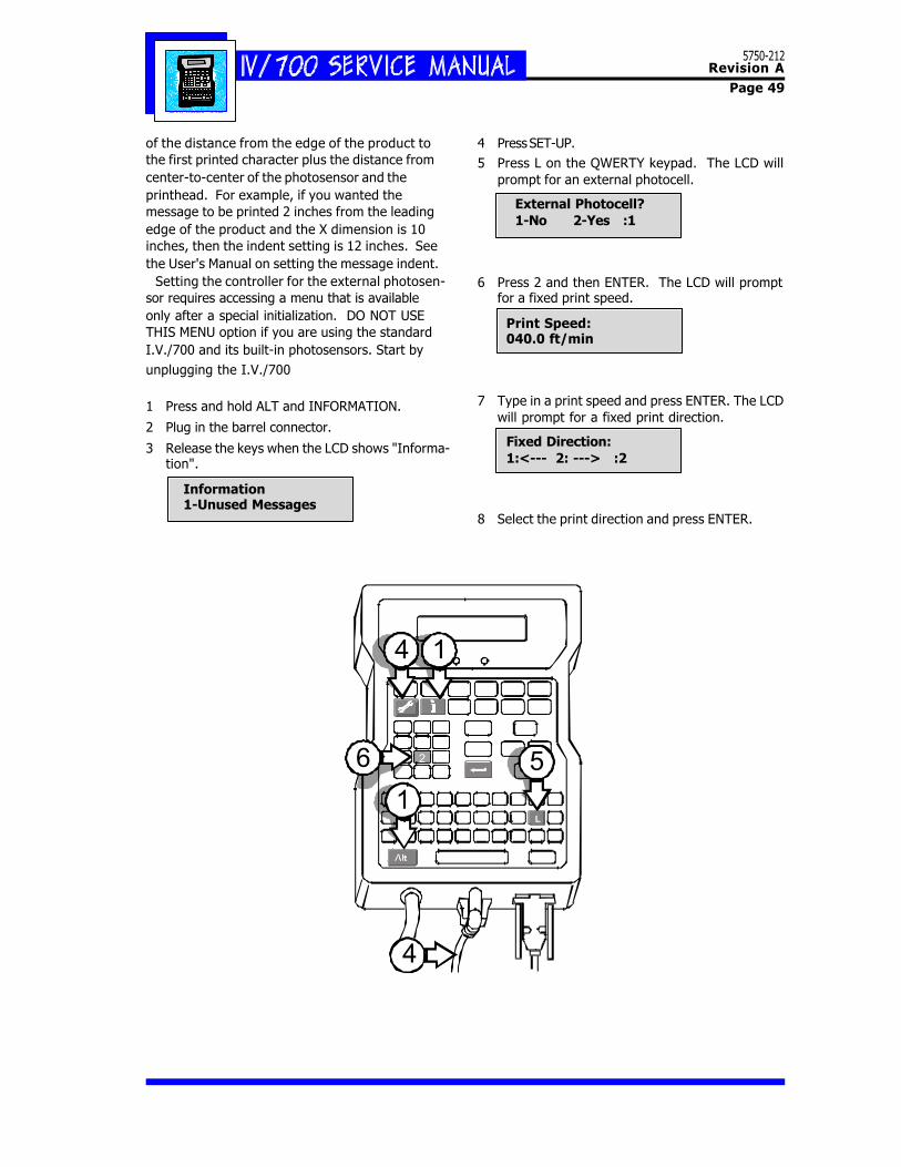
of the distance from the edge of the product tothe first printed character plus the distance fromcenter-to-center of the photosensor and theprinthead. For example, if you wanted themessage to be printed 2 inches from the leadingedge of the product and the X dimension is 10inches, then the indent setting is 12 inches. Seethe User's Manual on setting the message indent. Setting the controller for the external photosen-sor requires accessing a menu that is availableonly after a special initialization. DO NOT USETHIS MENU option if you are using the standardI.V./700 and its built-in photosensors. Start byunplugging the I.V./700
1 Press and hold ALT and INFORMATION.
2 Plug in the barrel connector.
3 Release the keys when the LCD shows "Informa-tion".
Information 1-Unused Messages
4 Press SET-UP.5 Press L on the QWERTY keypad. The LCD will
prompt for an external photocell.
External Photocell? 1-No 2-Yes :1
6 Press 2 and then ENTER. The LCD will promptfor a fixed print speed.
Print Speed: 040.0 ft/min
7 Type in a print speed and press ENTER. The LCDwill prompt for a fixed print direction.
Fixed Direction: 1:<--- 2: ---> :2
8 Select the print direction and press ENTER.
5750-212Revision A
Page 50
I . V . / 7 0 0 B r o a c h K i t 1 9 0 2 - 8 5 7 N
WARNING: Improper use of a broach can damagethe printhead membrane.
1. Make sure the broach pin does not extend out ofthe handle any more than 0.10 inch. This willensure that the broach pin will not poke a holein the membrane and cause internal leaking.
2. Wipe the front plate clean with a cloth and con-ditioner.
3. Identify the clogged orifice by identifying themissing dot(s) from a print sample.
4. Count the orifices on the front plate up or downuntil you locate the clogged orifice. A flashlightor other concentrated light source will help, asthe orifices are very small.
5. Carefully insert the broach pin in the cloggedorifice until the handle touches the front plate.Remove the broach pin from the orifice and cre-ate a print sample.
NOTE: Avoid broaching repeatedly. The broachpin is like a microscopic file that with repeatedinsertions will enlarge the orifice. The enlargedorifice will seep ink, print off target, or produceother print anomalies.
6. If the print sample shows that the orifice is stillclogged, purge the printhead and make a sec-ond print sample.
7. If orifice is still clogged, count the orifices againto make sure that you are broaching the correctorifice.
8. If orifice is still clogged, repeat steps 5 to 6.
[1]
0.10 inch
[3]
This broach kit works with bothsingle and double column (asshown below) models of I.V.printheads.