188
IVI-4.2: IviDmm Class Specification October 14, 2016 Edition Revision 4.1 Interchangeable Instruments Virtual IVI
!
IVI-4.2: IviDmm Class Specification
October 14, 2016 EditionRevision 4.1
Interchangeable
InstrumentsVirtualIVI

IVI-4.2: IviDmm Class Specification ! IVI Foundation 2
Important InformationThe IviDmm Class Specification (IVI-4.2) is authored by the IVI Foundation member companies. For a vendor membership roster list, please visit the IVI Foundation web site at www.ivifoundation.org, or contact the IVI Foundation.
The IVI Foundation wants to receive your comments on this specification. See the IVI Foundation web site for contact information.
Warranty
The IVI Foundation and its member companies make no warranty of any kind with regard to this material, including, but not limited to, the implied warranties of merchantability and fitness for a particular purpose. The IVI Foundation and its member companies shall not be liable for errors contained herein or for incidental or consequential damages in connection with the furnishing, performance, or use of this material.
Trademarks
Product and company names listed are trademarks or trade names of their respective companies.
No investigation has been made of common-law trademark rights in any work.
!
IviDmm Class Specification 8 .......................................................................
1.Overview of the IviDmm Specification 10 ................................................1.1.Introduction 10 1.2.IviDmm Class Overview 10 ..........................................................................................................................1.3.References 10 1.4.Definitions of Terms and Acronyms 10 ........................................................................................................
2.IviDmm Class Capabilities 12 ....................................................................2.1.Introduction 12 2.2.IviDmm Group Names 12 .............................................................................................................................2.3.Repeated Capability Names 13 .....................................................................................................................2.4.Boolean Attribute and Parameter Values 13 ..................................................................................................2.5..NET Namespace 13 2.6..NET IviDmm Session Factory 13 ................................................................................................................
3.General Requirements 16 ..........................................................................3.1.Minimum Class Compliance 16 ....................................................................................................................
3.1.1.Disable 17 3.2.Capability Group Compliance 17 ..................................................................................................................
IVI Foundation ! IVI-4.2: IviDmm Class Specification 3

4.IviDmmBase Capability Group 18 .............................................................4.1.Overview 18 4.2.IviDmmBase Attributes 18 ............................................................................................................................
4.2.1.Function 19 4.2.2.Range 25 4.2.3.AutoRange (IVI .NET only) 28 .........................................................................................4.2.4.Resolution Absolute 29 4.2.5.Trigger Delay 30 4.2.6.Trigger Delay Auto (IVI .NET Only) 32 ...........................................................................4.2.7.Trigger Source 33
4.3.IviDmmBase Functions 37 ............................................................................................................................4.3.1.Abort 38 4.3.2.Configure Measurement 39 4.3.3.Configure Trigger 41 4.3.4.Fetch 42 4.3.5.Initiate 45 4.3.6.Is Out Of Range (IVI.NET Only) 46 .................................................................................4.3.7.Is Over Range 47 4.3.8.Is Under Range (IVI.NET Only) 48 ..................................................................................4.3.9.Read 49
4.4.IviDmmBase Behavior Model 51 .................................................................................................................
5.IviDmmACMeasurement Extension Group 53 .........................................5.1.IviDmmACMeasurement Overview 53 ........................................................................................................5.2.IviDmmACMeasurement Attributes 53 ........................................................................................................
5.2.1.AC Max Freq 54 5.2.2.AC Min Freq 55
5.3.IviDmmACMeasurement Functions 56 ........................................................................................................5.3.1.Configure AC Bandwidth 57
5.4.IviDmmACMeasurement Behavior Model 58 ..............................................................................................5.5.IviDmmACMeasurement Compliance Notes 58 ..........................................................................................
6.IviDmmFrequencyMeasurement Extension Group 59 ............................6.1.IviDmmFrequencyMeasurement Overview 59 .............................................................................................6.2.IviDmmFrequencyMeasurement Attributes 59 .............................................................................................
6.2.1.Frequency Voltage Range 60 6.2.2.Frequency Voltage Range Auto (IVI.NET Only) 62 .........................................................
6.3.IviDmmFrequencyMeasurement Functions 63 .............................................................................................6.3.1.Configure Frequency Voltage Range (IVI-C Only) 64 .....................................................
6.4.IviDmmFrequencyMeasurement Behavior Model 65 ...................................................................................6.5.IviDmmFrequencyMeasurement Compliance Notes 65 ...............................................................................
7.IviDmmTemperatureMeasurement Extension Group 66 .........................7.1.IviDmmTemperatureMeasurement Overview 66 ..........................................................................................7.2.IviDmmTemperatureMeasurement Attributes 66 ..........................................................................................
7.2.1.Temperature Transducer Type 67 ......................................................................................7.3.IviDmmTemperatureMeasurement Functions 70 ..........................................................................................
7.3.1.Configure Transducer Type (IVI-C Only) 71 ....................................................................7.4.IviDmmTemperatureMeasurement Behavior Model 72 ...............................................................................7.5.IviDmmTemperatureMeasurement Compliance Notes 72 ............................................................................
8.IviDmmThermocouple Extension Group 73 .............................................8.1.IviDmmThermocouple Extension Group Overview 73 ................................................................................
IVI-4.2: IviDmm Class Specification ! IVI Foundation 4

8.2.IviDmmThermocouple Attributes 73 ............................................................................................................8.2.1.Thermocouple Fixed Reference Junction 74 .....................................................................8.2.2.Thermocouple Reference Junction Type 75 ......................................................................8.2.3.Thermocouple Type 77
8.3.IviDmmThermocouple Functions 82 ............................................................................................................8.3.1.Configure Fixed Reference Junction (IVI-C Only) 83 ......................................................8.3.2.Configure Thermocouple 84
8.4.IviDmmThermocouple Behavior Model 85 ..................................................................................................8.5.IviDmmThermocouple Compliance Notes 85 ..............................................................................................
9.IviDmmResistanceTemperatureDevice Extension Group 86 .................9.1.IviDmmResistanceTemperatureDevice Extension Group Overview 86 .......................................................9.2.IviDmmResistanceTemperatureDevice Attributes 86 ...................................................................................
9.2.1.RTD Alpha 87 9.2.2.RTD Resistance 88
9.3.IviDmmResistanceTemperatureDevice Functions 89 ...................................................................................9.3.1.Configure RTD 90
9.4.IviDmmResistanceTemperatureDevice Behavior Model 91 .........................................................................9.5.IviDmmResistanceTemperatureDevice Compliance Notes 91 .....................................................................
10.IviDmmThermistor Extension Group 92 .................................................10.1.IviDmmThermistor Extension Group Overview 92 ....................................................................................10.2.IviDmmThermistor Attributes 92 ................................................................................................................
10.2.1.Thermistor Resistance 93 10.3.IviDmmThermistor Functions 94 ................................................................................................................
10.3.1.Configure Thermistor (IVI-C Only) 95 ...........................................................................10.4.IviDmmThermistor Behavior Model 96 .....................................................................................................10.5.IviDmmThermistor Compliance Notes 96 ..................................................................................................
11.IviDmmMultiPoint Extension Group 97 ..................................................11.1.IviDmmMultiPoint Extension Group Overview 97 ....................................................................................11.2.IviDmmMultiPoint Attributes 97 ................................................................................................................
11.2.1.Measure Complete Destination 98 ..................................................................................11.2.2.Sample Count 102 11.2.3.Sample Interval 103 11.2.4.Sample Trigger 104 11.2.5.Trigger Count 108
11.3.IviDmmMultiPoint Functions 109 ..............................................................................................................11.3.1.Configure Measure Complete Destination (IVI-C Only) 110 .........................................11.3.2.Configure Multi Point 111 11.3.3.Fetch Multi Point 113 11.3.4.Read Multi Point 117
11.4.IviDmmMultiPoint Behavior Model 120 ....................................................................................................
12.IviDmmTriggerSlope Extension Group 122 ............................................12.1.IviDmmTriggerSlope Extension Group Overview 122 ..............................................................................12.2.IviDmmTriggerSlope Attributes 122 ...........................................................................................................
12.2.1.Trigger Slope 123 12.3.IviDmmTriggerSlope Functions 125 ...........................................................................................................
12.3.1.Configure Trigger Slope (IVI-C Only) 126 .....................................................................12.4.IviDmmTriggerSlope Behavior Model 127 ................................................................................................
IVI Foundation ! IVI-4.2: IviDmm Class Specification 5

13.IviDmmSoftwareTrigger Extension Group 128 ......................................13.1.IviDmmSoftwareTrigger Extension Group Overview 128 .........................................................................13.2.IviDmmSoftwareTrigger Functions 128 .....................................................................................................
13.2.1.IviDmm_SendSoftwareTrigger 128 ................................................................................13.3.IviDmmSoftwareTrigger Behavior Model 128 ...........................................................................................13.4.IviDmmSoftwareTrigger Compliance Notes 128 .......................................................................................
14.IviDmmDeviceInfo Extension Group 129 ...............................................14.1.IviDmmDeviceInfo Extension Group Overview 129 .................................................................................14.2.IviDmmDeviceInfo Attributes 129 ..............................................................................................................
14.2.1.Aperture Time 130 14.2.2.Aperture Time Units 131
14.3.IviDmmDeviceInfo Functions 132 ..............................................................................................................14.3.1.Get Aperture Time Info (IVI-C Only) 133 ......................................................................
14.4.IviDmmDeviceInfo Behavior Model 134 ...................................................................................................
15.IviDmmAutoRangeValue Extension Group 135 .....................................15.1.IviDmmAutoRangeValue Extension Group Overview 135 ........................................................................15.2.IviDmmAutoRangeValue Attributes 135 ....................................................................................................
15.2.1.Auto Range Value (IVI-C and IVI-COM Only) 136 .......................................................15.3.IviDmmAutoRangeValue Functions 137 ....................................................................................................
15.3.1.Get Auto Range Value (IVI-C Only) 138 ........................................................................15.4.IviDmmAutoRangeValue Behavior Model 139 ..........................................................................................15.5.IviDmmAutoRangeValue Compliance Notes 139 ......................................................................................
16.IviDmmAutoZero Extension Group 140 ..................................................16.1.IviDmmAutoZero Extension Group Overview 140 ....................................................................................16.2.IviDmmAutoZero Attributes 140 ................................................................................................................
16.2.1.Auto Zero 141 16.3.IviDmmAutoZero Functions 143 ................................................................................................................
16.3.1.Configure Auto Zero Mode (IVI-C Only) 144 ................................................................16.4.IviDmmAutoZero Behavior Model 145 ......................................................................................................
17.IviDmmPowerLineFrequency Extension Group 146 .............................17.1.IviDmmPowerLineFrequency Extension Group Overview 146 .................................................................17.2.IviDmmPowerLineFrequency Attributes 146 .............................................................................................
17.2.1.Powerline Frequency 147 17.3.IviDmmPowerLineFrequency Functions 148 .............................................................................................
17.3.1.Configure Power Line Frequency (IVI-C Only) 149 ......................................................17.4.IviDmmPowerLineFrequency Behavior Model 150 ...................................................................................
18.IviDmm Attribute ID Definitions 151 .......................................................18.1.IviDmm Obsolete Attribute Names 152 ......................................................................................................18.2.IviDmm Obsolete Attribute ID Values 152 ................................................................................................
19.IviDmm Attribute Value Definitions 153 ..................................................19.1.IviDmm Obsolete Attribute Value Names 166 ............................................................................................
IVI-4.2: IviDmm Class Specification ! IVI Foundation 6

20.IviDmm Function Parameter Value Definitions 168 ...............................
21.IviDmm Error, Completion Code, and Exception Class Definitions ...169
21.1.IviDmm Obsolete Error and Completion Code Names 170 .......................................................................21.2.IviDmm Obsolete Error and Completion Code Values 170 ........................................................................
22.IviDmm Hierarchies 171 ...........................................................................22.1.IviDmm ,NET Hierarchy 171 ......................................................................................................................
22.1.1.IviDmm.NET Interfaces 173 22.1.2..NET Interface Reference Properties 174 ........................................................................
22.2.IviDmm COM Hierarchy 175 .....................................................................................................................22.2.1.IviDmm COM Interfaces 177 22.2.2.Interface Reference Properties 178 .................................................................................22.2.3.IviDmm COM Category 178
22.3.IviDmm C Function Hierarchy 179 ............................................................................................................22.3.1.Ivi Dmm Obsolete Function Names 181 .........................................................................
22.4.IviDmm C Attribute Hierarchy 182 ............................................................................................................
A. Specific Driver Development Guidelines 184 ......................A.1. Introduction 184 A.2. Disabling Unused Extension Groups 184 ...............................................................................................A.3. Special Consideration for Query Instrument Status 185 .........................................................................A.4. Special Considerations for Sample Trigger 185 ......................................................................................A.5. Special Considerations for Auto Range Value 186 .................................................................................
B. Interchangeability Checking Rules 187 ................................B.1. Introduction 187 B.2. When to Perform Interchangeability Checking 187 ................................................................................B.3. Interchangeability Checking Rules 187..................................................................................................
IVI Foundation ! IVI-4.2: IviDmm Class Specification 7

IviDmm Class Specification IviDmm Revision History
This section is an overview of the revision history of the IviDmm specification.
Table 1-1 IviDmm Class Specification Revisions
Revision Number Date of Revision Revision Notes
Revision 1.0 August 21, 1998 First Approved Version.
Revision 2.0 November 22, 1999 This edition refines the organization of the specification based on feedback at the July 1999 IVI Foundation meeting. It replaces the IviDmm Miscellaneous Capabilities extension group by defining a new extension for every attribute in the group. It also defines new extension groups for AC, Frequency, and Temperature measurements.
Revision 3.0 (VC1)
July 27, 2001 Reformatted to adhere to formatting specified in IVI – 3.4: API Style Guide. Added COM interface.
Revision 3.0 (VC2)
November 8, 2001 Updates from Boston meeting, Steve Greer’s review feedback, J. Harvey’s COM feedback, and internal review.
Revision 3.0 (VC3)
December 18, 2001 Updates from Austin meeting. Some IDL changes still needed.
Revision 3.0(VC4) January 30, 2002 Updates from review feedback. Some IDL changes still needed.
Revision 3.0 (VC5)
March 8, 2002 Update TimeOut parameter names with MaxTimeMilliseconds. Updated "IviDmmTriggerSourceSoftware" to agree with IDL and Trigger source value of "IviDmmTriggerSourceSwTrigFunc". Added updated IDL.
Revision 3.0 April 16, 2002 Accepted changes. Removed draft. Added release IDL.
Revision 3.0 January 19, 2004 Changed name of ‘IsOverRange’ to ‘IsOver’ for Measurement.IsOverRange COM method prototype. Change reflected in body of specification and IviDmm IDL version 13.
Revision 3.0 April 29, 2008 Editorial change to update the IVI Foundation contact information in the Important Information section to remove obsolete address information and refer only to the IVI Foundation web site.
Revision 4.0 June 9, 2010 Incorporated IVI.NET
Revision 4.1 October 14, 2010 Correct reference to DelayAuto property in Sec. 22.1
IVI-4.2: IviDmm Class Specification ! IVI Foundation 8

API Versions
Drivers that comply with this version of the specification also comply with earlier, compatible, versions of the specification as shown in the table above. The driver may benefit by advertising that it supports all the API versions listed in the table above.
Revision 4.1 August 25, 2011 Editorial IVI.NET change. Change references to process-wide locking to AppDomain-wide locking. Add an overload to the Create factory method that takes locking related parameters.
Revision 4.1 November 12, 2013 Editorial change in Section 19 to update IVI.NET attribute value names for Auto Range attribute
Revision 4.1 November 26, 2014 Editorial change to fix the formatting of section 6.3.1
Revision 4.1 October 14, 2016 Editorial Change – Modified header text for table 21.2 to indicate that the messages do not apply to .NET exceptions.
Table 1-1 IviDmm Class Specification Revisions
Architecture Drivers that comply with version 4.0 comply with all of the versions below
C 2.0, 3.0, 4.0
COM 3.0, 4.0
.NET 4.0
IVI Foundation ! IVI-4.2: IviDmm Class Specification 9

1.Overview of the IviDmm Specification
1.1.Introduction This specification defines the IVI class for digital multimeters (DMMs). The IviDmm class is designed to support the typical DMM as well as common extended functionality found in more complex instruments. This section summarizes the IviDmm Class Specification and contains general information that the reader might need in order to understand, interpret, and implement aspects of this specification. These aspects include the following: • IviDmm class overview • The definitions of terms and acronyms • References
1.2.IviDmm Class Overview This specification defines the IVI class for digital multimeters (DMMs). The IviDmm class is designed to support the typical DMM as well as common extended functionality found in more complex instruments. The IviDmm class conceptualizes a DMM as an instrument that can measure scalar quantities of an input signal and can be applied to a wide variety of instruments. Typically the measured quantity is a voltage (AC and DC), current, or resistance. However, the IviDmm class can support instruments that measure other quantities such as temperature and frequency etc.
The IviDmm class is divided into a base capability group and several extension groups. The base capability group is used to configure a DMM for a typical measurement (this includes setting the measurement function, desired range, desired resolution, and trigger source), initiating that measurement, and returning a measured value. The IviDmm base capability group is described in Section 4, IviDmmBase Capability Group.
Many DMMs support measurement types that require additional parameters to be configured, such as the minimum and maximum frequency of the input signal for AC measurements. The IviDmm class defines extension groups for each measurement type that requires these additional parameters.
The IviDmm class also defines an extension group called IviDmmMultiPoint. The IviDmmMultiPoint extension group is used to configure DMMs that can acquire multiple measurements based on multiple triggers and take multiple measurements per trigger. This type of instrument used in conjunction with a scanner is typically used to implement a scanning DMM. The IviDmmMultiPoint extensions are described in Section 11, IviDmmMultiPoint Extension Group.
In addition, the IviDmm class defines extension groups that configure advanced settings such as auto-zero and power line frequency, or return additional information about the current state of the instrument such as aperture time. These extension groups are defined in Sections 12 through 17.
1.3.References Several other documents and specifications are related to this specification. These other related documents are as follows: • IVI-3.1: Driver Architecture Specification • IVI-3.2: Inherent Capabilities Specification • IVI-3.3: Standard Cross Class Capabilities Specification • IVI-3.18: IVI.NET Utility Classes and Interfaces Specification • IVI- 5.0: Glossary
1.4.Definitions of Terms and Acronyms This section defines terms and acronyms that are specific to the IviDmm class.
IVI-4.2: IviDmm Class Specification ! IVI Foundation 10

Temperature Transducer A device that converts thermal energy into electrical energy. Used for measuring temperature.
Reference Junction Also known as the Cold Junction. The junction of a thermocouple that is kept at a known temperature or one for which the temperature may be measured.
Refer to IVI–5.0: Glossary for a description of more terms used in this specification.
IVI Foundation ! IVI-4.2: IviDmm Class Specification 11

2.IviDmm Class Capabilities
2.1.Introduction The IviDmm specification divides DMM capabilities into a base capability group and multiple extension capability groups. Each capability group is discussed in a separate section. This section defines names for each capability group and gives an overview of the information presented for each capability group.
2.2.IviDmm Group Names The capability group names for the IviDmm class are defined in the following table. The Group Name is used to represent a particular capability group and is returned as one of the possible group names from the Class Group Capabilities attribute.
Table 2-1. IviDmm Group Names
Group Name Description
IviDmmBase Base Capability Group: DMM that complies with the IviDmmBase Capability Group.
IviDmmACMeasurement Extension Group: DMM with the capability to measure AC voltage, AC current, AC plus DC voltage, and AC plus DC current.
IviDmmFrequencyMeasurement Extension Group: DMM with the capability to measure frequency and period.
IviDmmTemperatureMeasurement Extension Group: DMM with the capability to measure temperature.
IviDmmThermocouple Extension Group: DMM with the capability to measure temperature using a thermocouple.
IviDmmResistanceTemperatureDevice Extension group: DMM with the capability to measure temperature using a temperature resistance device.
IviDmmThermistor Extension group: DMM with the capability to measure temperature using a thermistor.
IviDmmMultiPoint Extension Group: DMM with the capability to accept multiple triggers and acquire multiple samples per trigger.
IviDmmTriggerSlope Extension Group: DMM with the capability to specify the trigger slope.
IviDmmSoftwareTrigger Extension Group: DMM with the capability to send a software trigger.
IviDmmDeviceInfo Extension Group: DMM with the capability to return extra information concerning the instrument’s state such as aperture time.
IviDmmAutoRangeValue Extension Group: DMM with the capability to return the actual range when auto ranging.
IviDmmAutoZero Extension Group: DMM with the capability to take an auto-zero reading.
IVI-4.2: IviDmm Class Specification ! IVI Foundation 12

2.3.Repeated Capability Names
The IviDmm Class Specification does not define repeated capabilities.
2.4.Boolean Attribute and Parameter Values
This specification uses True and False as the values for Boolean attributes and parameters. The following table defines the identifiers that are used for True and False in the IVI.NET, IVI-COM, and IVI-C architectures.
2.5..NET Namespace
The .NET namespace for the IviDmm class is Ivi.Dmm.
2.6..NET IviDmm Session Factory
The IviDmm .NET assembly contains a factory method called Create for creating instances of IviDmm class-compliant IVI.NET drivers from driver sessions and logical names. Create is a static method accessible from the static IviDmm class.
Refer to IVI-3.5: Configuration Server Specification for a description of how logical names and session names are defined in the configuration store.
Refer to Section 8, IVI.NET Specific Driver Constructor, of IVI-3.2: Inherent Capabilities Specification, for more details on how the idQuery, reset, and options parameters affect the instantiation of the driver.
Refer to Section 4.3.11, Multithread Safety, of IVI-3.1: Driver Architecture Specification for a complete description of IVI.NET driver locking. Refer to Section 8, Table 8.2 Required Lock Type Behavior for Drivers With the Same Access Key, of IVI-3.2, Inherent Capability Specification, for an explanation of how the values for lockType and accessKey are used to determine the kind of multithreaded lock to use for the driver instance.
.NET Method Prototype IIviDmm Ivi.Dmm.Create(String name);
IIviDmm Ivi.Dmm.Create(String name, Boolean idQuery, Boolean reset);
IIviDmm Ivi.Dmm.Create(String name, Boolean idQuery, Boolean reset, String options);
Table 2-1. IviDmm Group Names
Group Name Description
IviDmmPowerLineFrequency Extension Group: DMM with the capability to specify the power line frequency.
Boolean Value IVI.NET Identifier IVI-COM Identifier IVI-C Identifier
True true VARIANT_TRUE VI_TRUE
False false VARIANT_FALSE VI_FALSE
IVI Foundation ! IVI-4.2: IviDmm Class Specification 13

IIviDmm Ivi.Dmm.Create(String resourceName, Boolean idQuery, Boolean reset, LockType lockType, String accessKey, String options);
Parameters
Defined Values
.NET Exceptions The IVI-3.2: Inherent Capabilities Specification defines general exceptions that may be thrown, and warning events that may be raised, by this method.
Inputs Description Base Type
name A session name or a logical name that points to a session that uses an IVI.NET IviDmm class-compliant driver.
String
idQuery Specifies whether to verify the ID of the instrument. The default is False.
Boolean
reset Specifies whether to reset the instrument. The default is False.
Boolean
lockType Specifies whether to use AppDomain-wide locking or machine-wide locking.
Ivi.Driver.LockType
accessKey Specifies a user-selectable access key to identify the lock. Driver instances that are created with the same accessKey will be protected from simultaneous access by multiple threads within an AppDomain or across AppDomains, depending upon the value of the lockType parameter.
String
options A string that allows the user to specify the initial values of certain inherent attributes. The default is an empty string.
String
Outputs Description Base Type
Return Value Interface pointer to the IIviDmm interface of the driver referenced by session.
IIviDmm
Name Description
Language Identifier
AppDomain The lock is AppDomain-wide.
.NET Ivi.Driver.LockType.AppDomain
Machine The lock is machine-wide.
.NET Ivi.Driver.LockType.Machine
IVI-4.2: IviDmm Class Specification ! IVI Foundation 14

Usage
To create a driver that implements the IviDmm instrument class API from the logical name “My LogicalName” use the following:
IIviDmm dmm = IviDmm.Create(“MyLogicalName”);
In this case, the ID of the instrument will not be verified, the instrument will not be reset, and options will be supplied from the configuration store and/or driver defaults.
IVI Foundation ! IVI-4.2: IviDmm Class Specification 15

3.General Requirements This section describes the general requirements a specific driver must meet in order to be compliant with this specification. In addition, it provides general requirements that specific drivers must meet in order to comply with a capability group, attribute, or function.
3.1.Minimum Class Compliance
To be compliant with the IviDmm Class Specification, an IVI specific driver shall conform to all of the requirements for an IVI class-compliant specific driver as specified in IVI-3.1: Driver Architecture Specification, implement the inherent capabilities that IVI-3.2: Inherent IVI Capabilities Specification defines, and implements the IviDmmBase capability group.
IVI-4.2: IviDmm Class Specification ! IVI Foundation 16

3.1.1.Disable Refer to IVI-3.2: Inherent Capabilities Specification for the prototype of this function. The IviDmm specification does not define additional requirements on the Disable function.
3.2.Capability Group Compliance IVI-3.1: Driver Architecture Specification defines the general rules for a specific driver to be compliant with a capability group.
IVI Foundation ! IVI-4.2: IviDmm Class Specification 17

4.IviDmmBase Capability Group
4.1.Overview The IviDmmBase Capability Group supports DMMs that take a single measurement at a time. The IviDmmBase Capability Group defines attributes and their values to configure the type of measurement and how the measurement is to be performed. These attributes include the measurement function, range, resolution, and trigger source. The IviDmmBase capability group also includes functions for configuring the DMM as well as initiating and retrieving measurements.
4.2.IviDmmBase Attributes The IviDmmBase capability group defines the following attributes: • Function • Range • Resolution Absolute • Trigger Delay • Trigger Source
This section describes the behavior and requirements of each attribute. The actual value for each attribute ID is defined in Section 18, IviDmm Attribute ID Definitions.
IVI-4.2: IviDmm Class Specification ! IVI Foundation 18

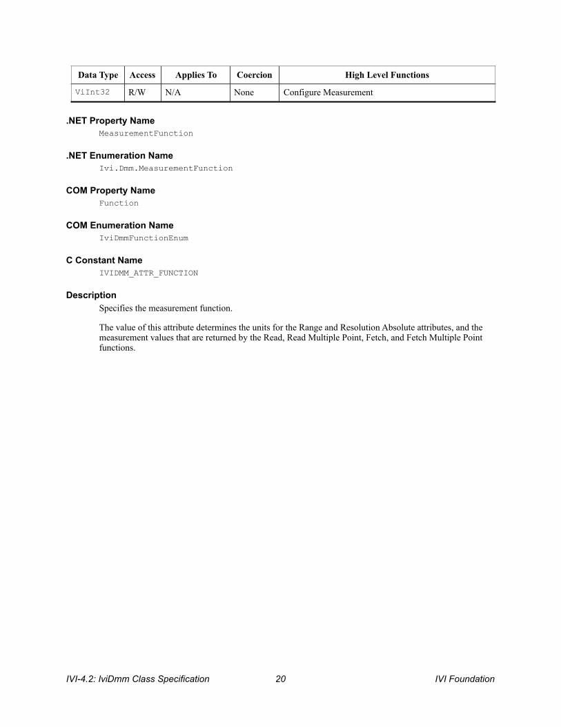
4.2.1.Function
IVI Foundation ! IVI-4.2: IviDmm Class Specification 19
.NET Property Name MeasurementFunction
.NET Enumeration Name Ivi.Dmm.MeasurementFunction
COM Property Name Function
COM Enumeration Name IviDmmFunctionEnum
C Constant Name IVIDMM_ATTR_FUNCTION
Description Specifies the measurement function.
The value of this attribute determines the units for the Range and Resolution Absolute attributes, and the measurement values that are returned by the Read, Read Multiple Point, Fetch, and Fetch Multiple Point functions.
Data Type Access Applies To Coercion High Level Functions
ViInt32 R/W N/A None Configure Measurement
IVI-4.2: IviDmm Class Specification ! IVI Foundation 20

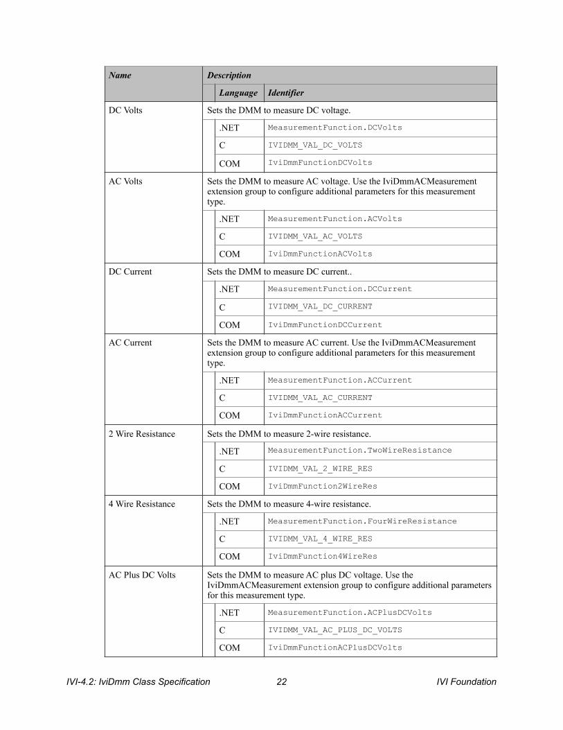
Defined Values
IVI Foundation ! IVI-4.2: IviDmm Class Specification 21
Name Description
Language Identifier
DC Volts Sets the DMM to measure DC voltage.
.NET MeasurementFunction.DCVolts
C IVIDMM_VAL_DC_VOLTS
COM IviDmmFunctionDCVolts
AC Volts Sets the DMM to measure AC voltage. Use the IviDmmACMeasurement extension group to configure additional parameters for this measurement type.
.NET MeasurementFunction.ACVolts
C IVIDMM_VAL_AC_VOLTS
COM IviDmmFunctionACVolts
DC Current Sets the DMM to measure DC current..
.NET MeasurementFunction.DCCurrent
C IVIDMM_VAL_DC_CURRENT
COM IviDmmFunctionDCCurrent
AC Current Sets the DMM to measure AC current. Use the IviDmmACMeasurement extension group to configure additional parameters for this measurement type.
.NET MeasurementFunction.ACCurrent
C IVIDMM_VAL_AC_CURRENT
COM IviDmmFunctionACCurrent
2 Wire Resistance Sets the DMM to measure 2-wire resistance.
.NET MeasurementFunction.TwoWireResistance
C IVIDMM_VAL_2_WIRE_RES
COM IviDmmFunction2WireRes
4 Wire Resistance Sets the DMM to measure 4-wire resistance.
.NET MeasurementFunction.FourWireResistance
C IVIDMM_VAL_4_WIRE_RES
COM IviDmmFunction4WireRes
AC Plus DC Volts Sets the DMM to measure AC plus DC voltage. Use the IviDmmACMeasurement extension group to configure additional parameters for this measurement type.
.NET MeasurementFunction.ACPlusDCVolts
C IVIDMM_VAL_AC_PLUS_DC_VOLTS
COM IviDmmFunctionACPlusDCVolts
IVI-4.2: IviDmm Class Specification ! IVI Foundation 22

.NET Exceptions The IVI-3.2: Inherent Capabilities Specification defines general exceptions that may be thrown, and warning events that may be raised, by this property.
Compliance Notes 1. If an IviDmm specific driver implements any of the defined values in the following table, it shall also
implement the corresponding capability group:
AC Plus DC Current Sets the DMM to measure AC plus DC current. Use the IviDmmACMeasurement extension group to configure additional parameters for this measurement type.
.NET MeasurementFunction.ACPlusDCCurrent
C IVIDMM_VAL_AC_PLUS_DC_CURRENT
COM IviDmmFunctionACPlusDCCurrent
Frequency Sets the DMM to measure frequency. Use the IviDmmFrequencyMeasurement extension group to configure additional parameters for this measurement type.
.NET MeasurementFunction.Frequency
C IVIDMM_VAL_FREQ
COM IviDmmFunctionFreq
Period Sets the DMM to measure period. Use the IviDmmFrequencyMeasurement extension group to configure additional parameters for this measurement type.
.NET MeasurementFunction.Period
C IVIDMM_VAL_PERIOD
COM IviDmmFunctionPeriod
Temperature Sets the DMM to measure temperature. Use the IviDmmTemperatureMeasurement extension group to configure additional parameters for this measurement type.
.NET MeasurementFunction.Temperature
C IVIDMM_VAL_TEMPERATURE
COM IviDmmFunctionTemperature
Name Description
Language Identifier
Value Required Capability Group
AC Volts IviDmmACMeasurement
AC Current IviDmmACMeasurement
AC Plus DC Volts IviDmmACMeasurement
AC Plus DC Current IviDmmACMeasurement
IVI Foundation ! IVI-4.2: IviDmm Class Specification 23

2. If an IVI-C IviDmm specific driver defines additional values for this attribute, the actual values shall be greater than or equal to Function Specific Extension Base.
3. If an IVI-C IviDmm class driver defines additional values for this attribute, the actual values shall be greater than or equal to Function Class Extension Base and less than Function Specific Extension Base.
4. When an IVI-COM specific driver implements this attribute with additional elements in its instrument specific interfaces, it is recommended that the actual values of the additional elements be greater than or equal to Function Specific Extension Base.
See Section 19, Attribute Value Definitions, for the definitions of Function Specific Extension Base and Function Class Extension Base.
Frequency IviDmmFrequencyMeasurement
Period IviDmmFrequencyMeasurement
Temperature IviDmmTemperatureMeasurement
IVI-4.2: IviDmm Class Specification ! IVI Foundation 24
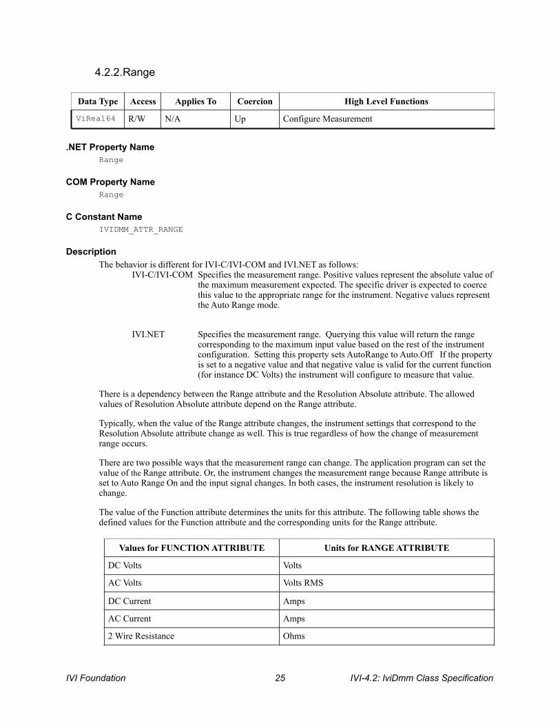
4.2.2.Range
.NET Property Name Range
COM Property Name Range
C Constant Name IVIDMM_ATTR_RANGE
Description The behavior is different for IVI-C/IVI-COM and IVI.NET as follows:
IVI-C/IVI-COM Specifies the measurement range. Positive values represent the absolute value of the maximum measurement expected. The specific driver is expected to coerce this value to the appropriate range for the instrument. Negative values represent the Auto Range mode.
IVI.NET Specifies the measurement range. Querying this value will return the range corresponding to the maximum input value based on the rest of the instrument configuration. Setting this property sets AutoRange to Auto.Off If the property is set to a negative value and that negative value is valid for the current function (for instance DC Volts) the instrument will configure to measure that value.
There is a dependency between the Range attribute and the Resolution Absolute attribute. The allowed values of Resolution Absolute attribute depend on the Range attribute.
Typically, when the value of the Range attribute changes, the instrument settings that correspond to the Resolution Absolute attribute change as well. This is true regardless of how the change of measurement range occurs.
There are two possible ways that the measurement range can change. The application program can set the value of the Range attribute. Or, the instrument changes the measurement range because Range attribute is set to Auto Range On and the input signal changes. In both cases, the instrument resolution is likely to change.
The value of the Function attribute determines the units for this attribute. The following table shows the defined values for the Function attribute and the corresponding units for the Range attribute.
Data Type Access Applies To Coercion High Level Functions
ViReal64 R/W N/A Up Configure Measurement
Values for FUNCTION ATTRIBUTE Units for RANGE ATTRIBUTE
DC Volts Volts
AC Volts Volts RMS
DC Current Amps
AC Current Amps
2 Wire Resistance Ohms
IVI Foundation ! IVI-4.2: IviDmm Class Specification 25
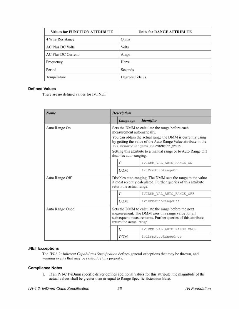
Defined Values There are no defined values for IVI.NET
.NET Exceptions The IVI-3.2: Inherent Capabilities Specification defines general exceptions that may be thrown, and warning events that may be raised, by this property.
Compliance Notes 1. If an IVI-C IviDmm specific driver defines additional values for this attribute, the magnitude of the
actual values shall be greater than or equal to Range Specific Extension Base.
4 Wire Resistance Ohms
AC Plus DC Volts Volts
AC Plus DC Current Amps
Frequency Hertz
Period Seconds
Temperature Degrees Celsius
Values for FUNCTION ATTRIBUTE Units for RANGE ATTRIBUTE
Name Description
Language Identifier
Auto Range On Sets the DMM to calculate the range before each measurement automatically. You can obtain the actual range the DMM is currently using by getting the value of the Auto Range Value attribute in the IviDmmAutoRangeValue extension group. Setting this attribute to a manual range or to Auto Range Off disables auto-ranging.
C IVIDMM_VAL_AUTO_RANGE_ON
COM IviDmmAutoRangeOn
Auto Range Off Disables auto-ranging. The DMM sets the range to the value it most recently calculated. Further queries of this attribute return the actual range.
C IVIDMM_VAL_AUTO_RANGE_OFF
COM IviDmmAutoRangeOff
Auto Range Once Sets the DMM to calculate the range before the next measurement. The DMM uses this range value for all subsequent measurements. Further queries of this attribute return the actual range.
C IVIDMM_VAL_AUTO_RANGE_ONCE
COM IviDmmAutoRangeOnce
IVI-4.2: IviDmm Class Specification ! IVI Foundation 26

2. If an IVI-C IviDmm class driver defines additional values for this attribute, the magnitude of the actual values shall be greater than or equal to Range Class Extension Base and less than Range Specific Extension Base.
3. When an IVI-COM specific driver implements this attribute with additional elements in its instrument specific interfaces, it is recommended that the actual values of the additional elements be greater than or equal to Range Specific Extension Base.
See Section 19, Attribute Value Definitions, for the definitions of Range Specific Extension Base and Range Class Extension Base.
IVI Foundation ! IVI-4.2: IviDmm Class Specification 27

4.2.3.AutoRange (IVI .NET only)
.NET Property Name AutoRange
.NET Enumeration Name Auto
COM Property Name N/A
C Constant Name N/A
Description Specifies if the instrument sets the range of the instrument automatically, as described in the following table.
Note that IVI-COM and IVI-C achieve this behavior by setting Range to defined values.
.NET Exceptions The IVI-3.2: Inherent Capabilities Specification defines general exceptions that may be thrown, and warning events that may be raised, by this property.
Data Type Access Applies To Coercion High Level Functions
ViInt32 R/W N/A N/A Configure Measurement
Name Description
Language Identifier
Auto On Sets the DMM to calculate the range before each measurement automatically. You can obtain the actual range the DMM is currently using by getting the value of the Range attribute. Setting the Range attribute also sets ththe Auto Range attribute to Auto Range Off.
.NET Auto.On
Auto Off Disables auto-ranging. The DMM sets the Range attribute to the value it most recently calculated. Further queries of the Range attribute return the actual range.
.NET Auto.Off
Auto Once Sets the DMM to calculate the range before the next measurement. After the next measurement, the DMM uses the calculated range value for all subsequent measurements. Further queries of the Range attribute return the actual range.
.NET Auto.Once
IVI-4.2: IviDmm Class Specification ! IVI Foundation 28

4.2.4.Resolution Absolute
.NET Property Name Resolution
COM Property Name Resolution
C Constant Name IVIDMM_ATTR_RESOLUTION_ABSOLUTE
Description Specifies the measurement resolution in absolute units.
The value of the Function attribute determines the units for this attribute. The following table shows the defined values for the Function attribute and the corresponding units for the Resolution Absolute attribute.
.NET Exceptions The IVI-3.2: Inherent Capabilities Specification defines general exceptions that may be thrown, and warning events that may be raised, by this property.
Data Type Access Applies To Coercion High Level Functions
ViReal64 R/W N/A Down Configure Measurement
Values for FUNCTION ATTRIBUTE Units for RESOLUTION ABSOLUTE ATTRIBUTE
DC Volts Volts
AC Volts Volts RMS
DC Current Amps
AC Current Amps RMS
2 Wire Resistance Ohms
4 Wire Resistance Ohms
AC Plus DC Volts Volts RMS
AC Plus DC Current Amps RMS
Frequency Hertz
Period Seconds
Temperature Degrees Celsius
IVI Foundation ! IVI-4.2: IviDmm Class Specification 29

4.2.5.Trigger Delay
Note Many DMMs have a small, non-zero value as the minimum value for this attribute. To configure the instrument to use the shortest trigger delay, the user can specify a value of zero for this attribute. Therefore, the specific driver must coerce any value between zero and the minimum value to the minimum value. No other coercion is allowed on this attribute.
.NET Property Name Trigger.Delay
COM Property Name Trigger.Delay
C Constant Name IVIDMM_ATTR_TRIGGER_DELAY
Description Specifies the length of time between when the DMM receives the trigger and when it takes a measurement.
The Trigger Delay is an explicit delay to take place between the instrument trigger event and the initiation of the measurement. This is typically used to account for settling in the signal path. When Auto Delay is set to on, the instrument selects an appropriate settling time for this configuration.
The behavior is different for IVI-C/IVI-COM and IVI.NET as follows:
IVI-C/IVI-COM Use positive values to set the trigger delay in seconds. Negative values are reserved for the auto delay mode.
IVI.NET The PrecisionTimeSpan units are implicit in the definition of PrecisionTimeSpan. Negative values do not have a special meaning but could be used to represent pre-trigger configurations. Setting this property also sets the Trigger Delay Auto attribute to false.
Defined Values IVI.NET does not have defined values.
Data Type Access Applies To Coercion High Level Functions
ViReal64 (C/COM) Ivi.Driver.PrecisionTimeSpan (.NET)
R/W N/A Note Configure Trigger
Name Description
Language Identifier
IVI-4.2: IviDmm Class Specification ! IVI Foundation 30
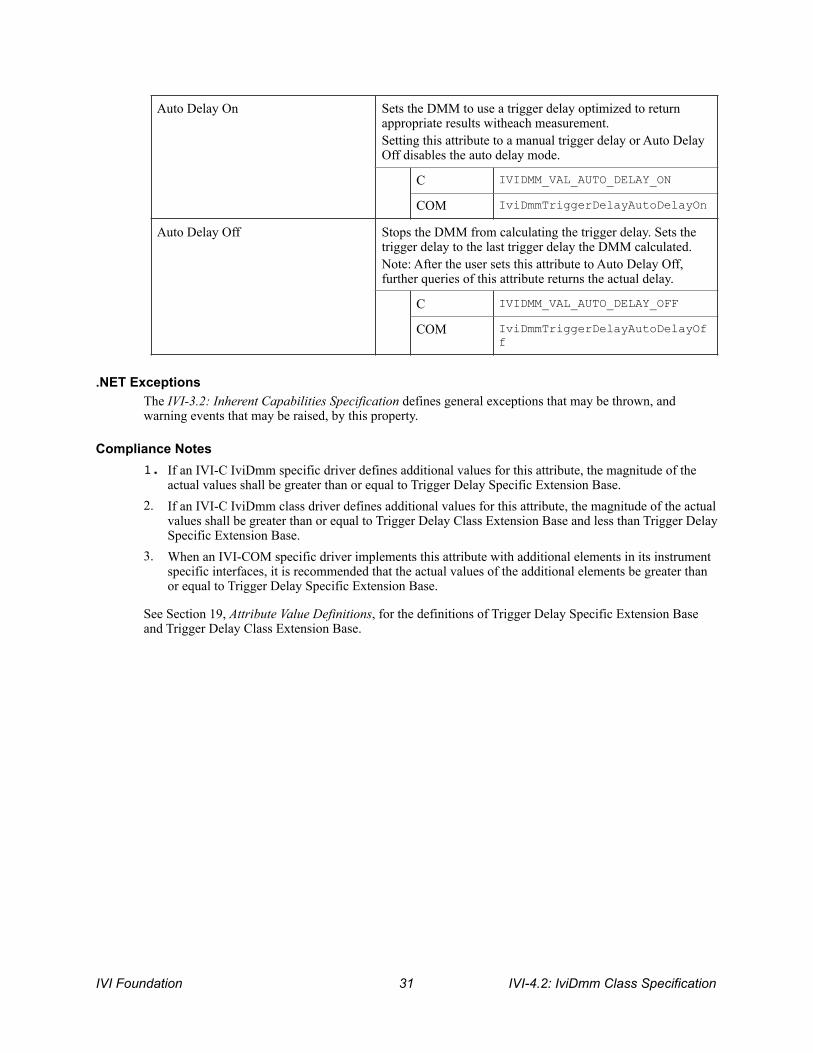
.NET Exceptions The IVI-3.2: Inherent Capabilities Specification defines general exceptions that may be thrown, and warning events that may be raised, by this property.
Compliance Notes 1. If an IVI-C IviDmm specific driver defines additional values for this attribute, the magnitude of the
actual values shall be greater than or equal to Trigger Delay Specific Extension Base.2. If an IVI-C IviDmm class driver defines additional values for this attribute, the magnitude of the actual
values shall be greater than or equal to Trigger Delay Class Extension Base and less than Trigger Delay Specific Extension Base.
3. When an IVI-COM specific driver implements this attribute with additional elements in its instrument specific interfaces, it is recommended that the actual values of the additional elements be greater than or equal to Trigger Delay Specific Extension Base.
See Section 19, Attribute Value Definitions, for the definitions of Trigger Delay Specific Extension Base and Trigger Delay Class Extension Base.
Auto Delay On Sets the DMM to use a trigger delay optimized to return appropriate results witheach measurement. Setting this attribute to a manual trigger delay or Auto Delay Off disables the auto delay mode.
C IVIDMM_VAL_AUTO_DELAY_ON
COM IviDmmTriggerDelayAutoDelayOn
Auto Delay Off Stops the DMM from calculating the trigger delay. Sets the trigger delay to the last trigger delay the DMM calculated. Note: After the user sets this attribute to Auto Delay Off, further queries of this attribute returns the actual delay.
C IVIDMM_VAL_AUTO_DELAY_OFF
COM IviDmmTriggerDelayAutoDelayOff
IVI Foundation ! IVI-4.2: IviDmm Class Specification 31

4.2.6.Trigger Delay Auto (IVI .NET Only)
.NET Property Name Trigger.DelayAuto
COM Property Name N/A
C Constant Name N/A
Description
If this attribute is True, the driver sets the DMM to use a trigger delay optimized to return appropriate results with each measurement.
If this attribute is False, the driver disables automatic calculation of trigger delay, and the value of the Delay attribute is used.
The actual trigger delay the DMM is currently using can be determined from the Trigger Delay attribute.
Setting the Trigger Delay attribute also sets the Trigger Delay Auto attribute to false.
Note that IVI-COM and IVI-C achieve this behavior by setting the Trigger Delay attribute to defined values.
.NET Exceptions
The IVI-3.2: Inherent Capabilities Specification defines general exceptions that may be thrown, and warning events that may be raised, by this property.
Data Type Access Applies To Coercion High Level Functions
ViBoolean R/W N/A N/A Configure Trigger
IVI-4.2: IviDmm Class Specification ! IVI Foundation 32

4.2.7.Trigger Source
.NET Property Name Trigger.Source
COM Property Name Trigger.Source
COM Enumeration Name IviDmmTriggerSourceEnum
C Constant Name IVIDMM_ATTR_TRIGGER_SOURCE
Description Specifies the trigger source.
Defined Values
In IVI.NET the trigger source is a string. If an IVI driver supports a trigger source and the trigger source is listed in IVI-3.3 Cross Class Capabilities Specification, Section 3, then the IVI driver shall accept the standard string for that trigger source. This attribute is case insensitive, but case preserving. That is, the setting is case insensitive but when reading it back the programmed case is returned. IVI specific drivers may define new trigger source strings for trigger sources that are not defined by IVI-3.3 Cross Class Capabilities Specification if needed.
Data Type Access Applies To Coercion High Level Functions
ViInt32 (C/COM) R/W N/A None ConfigureTrigger
ViString (.NET) R/W N/A None ConfigureTrigger
Name Description
Language Identifier
Immediate The DMM exits the Wait-For-Trigger state immediately after entering. It does not wait for a trigger of any kind.
C IVIDMM_VAL_IMMEDIATE
COM IviDmmTriggerSourceImmediate
External The DMM exits the Wait-For-Trigger state when a trigger occurs on the external trigger input.
C IVIDMM_VAL_EXTERNAL
COM IviDmmTriggerSourceExternal
Software Trigger The DMM exits the Wait-For-Trigger state when the Send Software Trigger function executes. Refer to the Standardized Cross Class Capabilities specification for a complete description of this value and the Send Software Trigger function.
C IVIDMM_VAL_SOFTWARE_TRIG
IVI Foundation ! IVI-4.2: IviDmm Class Specification 33

COM IviDmmTriggerSourceSwTrigFunc
TTL0 The DMM exits the Wait-For-Trigger state when it receives a trigger on TTL0.
C IVIDMM_VAL_TTL0
COM IviDmmTriggerSourceTTL0
TTL1 The DMM exits the Wait-For-Trigger state when it receives a trigger on TTL1.
C IVIDMM_VAL_TTL1
COM IviDmmTriggerSourceTTL1
TTL2 The DMM exits the Wait-For-Trigger state when it receives a trigger on TTL2.
C IVIDMM_VAL_TTL2
COM IviDmmTriggerSourceTTL2
TTL3 The DMM exits the Wait-For-Trigger state when it receives a trigger on TTL3.
C IVIDMM_VAL_TTL3
COM IviDmmTriggerSourceTTL3
TTL4 The DMM exits the Wait-For-Trigger state when it receives a trigger on TTL4.
C IVIDMM_VAL_TTL4
COM IviDmmTriggerSourceTTL4
TTL5 The DMM exits the Wait-For-Trigger state when it receives a trigger on TTL5.
C IVIDMM_VAL_TTL5
COM IviDmmTriggerSourceTTL5
TTL6 The DMM exits the Wait-For-Trigger state when it receives a trigger on TTL6.
C IVIDMM_VAL_TTL6
COM IviDmmTriggerSourceTTL6
TTL7 The DMM exits the Wait-For-Trigger state when it receives a trigger on TTL7.
C IVIDMM_VAL_TTL7
COM IviDmmTriggerSourceTTL7
ECL0 The DMM exits the Wait-For-Trigger state when it receives a trigger on ECL0.
Name Description
Language Identifier
IVI-4.2: IviDmm Class Specification ! IVI Foundation 34
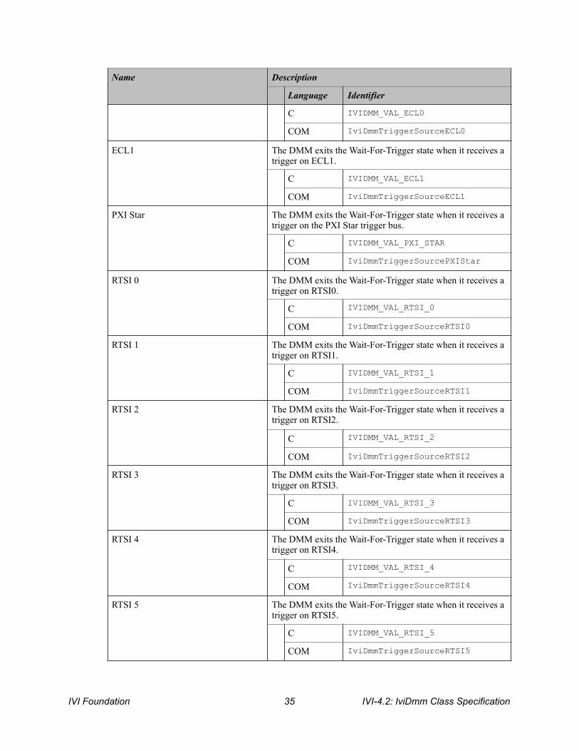
C IVIDMM_VAL_ECL0
COM IviDmmTriggerSourceECL0
ECL1 The DMM exits the Wait-For-Trigger state when it receives a trigger on ECL1.
C IVIDMM_VAL_ECL1
COM IviDmmTriggerSourceECL1
PXI Star The DMM exits the Wait-For-Trigger state when it receives a trigger on the PXI Star trigger bus.
C IVIDMM_VAL_PXI_STAR
COM IviDmmTriggerSourcePXIStar
RTSI 0 The DMM exits the Wait-For-Trigger state when it receives a trigger on RTSI0.
C IVIDMM_VAL_RTSI_0
COM IviDmmTriggerSourceRTSI0
RTSI 1 The DMM exits the Wait-For-Trigger state when it receives a trigger on RTSI1.
C IVIDMM_VAL_RTSI_1
COM IviDmmTriggerSourceRTSI1
RTSI 2 The DMM exits the Wait-For-Trigger state when it receives a trigger on RTSI2.
C IVIDMM_VAL_RTSI_2
COM IviDmmTriggerSourceRTSI2
RTSI 3 The DMM exits the Wait-For-Trigger state when it receives a trigger on RTSI3.
C IVIDMM_VAL_RTSI_3
COM IviDmmTriggerSourceRTSI3
RTSI 4 The DMM exits the Wait-For-Trigger state when it receives a trigger on RTSI4.
C IVIDMM_VAL_RTSI_4
COM IviDmmTriggerSourceRTSI4
RTSI 5 The DMM exits the Wait-For-Trigger state when it receives a trigger on RTSI5.
C IVIDMM_VAL_RTSI_5
COM IviDmmTriggerSourceRTSI5
Name Description
Language Identifier
IVI Foundation ! IVI-4.2: IviDmm Class Specification 35

.NET Exceptions The IVI-3.2: Inherent Capabilities Specification defines general exceptions that may be thrown, and warning events that may be raised, by this method.
Compliance Notes 1. If an IviDmm specific driver implements any of the defined values in the following table, it shall also
implement the corresponding capability group:
2. If an IVI-C IviDmm specific driver defines additional values for this attribute, the actual values shall be greater than or equal to Trigger Source Specific Extension Base.
3. If an IVI-C IviDmm class driver defines additional values for this attribute, the actual values shall be greater than or equal to Trigger Source Class Extension Base and less than Trigger Source Specific Extension Base.
4. When an IVI-COM specific driver implements this attribute with additional elements in its instrument specific interfaces, it is recommended that the actual values of the additional elements be greater than or equal to Trigger Source Specific Extension Base.
See Section 19, Attribute Value Definitions, for the definitions of Trigger Source Specific Extension Base and Trigger Source Class Extension Base.
RTSI 6 The DMM exits the Wait-For-Trigger state when it receives a trigger on RTSI6.
C IVIDMM_VAL_RTSI_6
COM IviDmmTriggerSourceRTSI6
Name Description
Language Identifier
Value Required Capability Group
Software Trigger IviDmmSoftwareTrigger
IVI-4.2: IviDmm Class Specification ! IVI Foundation 36
4.3.IviDmmBase Functions The IviDmmBase capability group defines the following functions: • Abort • Configure Measurement • Configure Trigger • Fetch • Initiate • Is Out Of Range (IVI.NET Only) • Is Over Range • Is Under Range (IVI.NET Only) • Read
This section describes the behavior and requirements of each function.
IVI Foundation ! IVI-4.2: IviDmm Class Specification 37

4.3.1.Abort
Description This function aborts a previously initiated measurement and returns the DMM to the idle state.
This function does not check the instrument status. Typically, the end-user calls this function only in a sequence of calls to other low-level driver functions. The sequence performs one operation. The end-user uses the low-level functions to optimize one or more aspects of interaction with the instrument. To check the instrument status, call the Error Query function at the conclusion of the sequence.
.NET Method Prototype void Measurement.Abort();
COM Method Prototype HRESULT Measurement.Abort();
C Prototype ViStatus IviDmm_Abort (ViSession Vi);
Parameters
Return Values (C/COM) The IVI-3.2: Inherent Capabilities Specification defines general status codes that this function can return.
.NET Exceptions The IVI-3.2: Inherent Capabilities Specification defines general exceptions that may be thrown, and warning events that may be raised, by this method.
Inputs Description Base Type
Vi Instrument handle ViSession
IVI-4.2: IviDmm Class Specification ! IVI Foundation 38

4.3.2.Configure Measurement
Description This function configures the common attributes of the DMM. These attributes include the measurement function, maximum range, and the resolution of the DMM.
If the value of the range parameter is Auto Range On, then the resolution parameter is ignored and the Resolution Absolute attribute is not set.
.NET Method Prototypes void Configure(MeasurementFunction measurementFunction, Auto autoRange, Double resolution);
void Configure(MeasurementFunction measurementFunction, Double range, Double resolution);
COM Method Prototype HRESULT Configure([in] IviDmmFunctionEnum Function, [in] DOUBLE Range, [in] DOUBLE Resolution);
C Prototype ViStatus IviDmm_ConfigureMeasurement (ViSession Vi, ViInt32 Function, ViReal64 Range, ViReal64 Resolution);
IVI Foundation ! IVI-4.2: IviDmm Class Specification 39
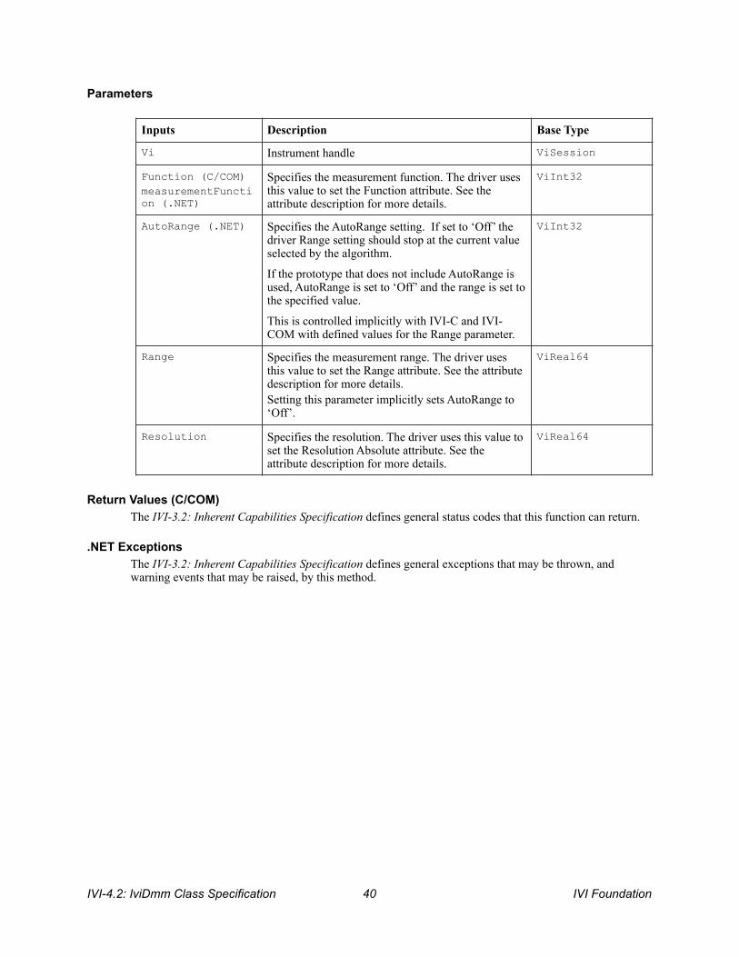
Parameters
Return Values (C/COM) The IVI-3.2: Inherent Capabilities Specification defines general status codes that this function can return.
.NET Exceptions The IVI-3.2: Inherent Capabilities Specification defines general exceptions that may be thrown, and warning events that may be raised, by this method.
Inputs Description Base Type
Vi Instrument handle ViSession
Function (C/COM) measurementFunction (.NET)
Specifies the measurement function. The driver uses this value to set the Function attribute. See the attribute description for more details.
ViInt32
AutoRange (.NET) Specifies the AutoRange setting. If set to ‘Off’ the driver Range setting should stop at the current value selected by the algorithm.
If the prototype that does not include AutoRange is used, AutoRange is set to ‘Off’ and the range is set to the specified value.
This is controlled implicitly with IVI-C and IVI-COM with defined values for the Range parameter.
ViInt32
Range Specifies the measurement range. The driver uses this value to set the Range attribute. See the attribute description for more details. Setting this parameter implicitly sets AutoRange to ‘Off’.
ViReal64
Resolution Specifies the resolution. The driver uses this value to set the Resolution Absolute attribute. See the attribute description for more details.
ViReal64
IVI-4.2: IviDmm Class Specification ! IVI Foundation 40

4.3.3.Configure Trigger
Description This function configures the common DMM trigger attributes. These attributes include the trigger source and the trigger delay.
.NET Method Prototype void Trigger.Configure(String triggerSource,
Boolean autoTriggerDelay)
void Trigger.Configure(String triggerSource,
Ivi.Driver.PrecisionTimeSpan triggerDelay);
COM Method Prototype HRESULT Trigger.Configure([in] IviDmmTriggerSourceEnum TriggerSource, [in] DOUBLE TriggerDelay);
C Prototype ViStatus IviDmm_ConfigureTrigger (ViSession Vi, ViInt32 TriggerSource, ViReal64 TriggerDelay);
Parameters
Return Values (C/COM) The IVI-3.2: Inherent Capabilities Specification defines general status codes that this function can return.
.NET Exceptions The IVI-3.2: Inherent Capabilities Specification defines general exceptions that may be thrown, and warning events that may be raised, by this method.
Inputs Description Base Type
Vi Instrument handle ViSession
TriggerSource Specifies the trigger source. The driver uses this value to set the Trigger Source attribute. See the attribute description for more details.
ViInt32
autoTriggerDelay (.NET)
Specifies TriggerDelay setting. If set to ‘True’ the triggerDelay parameter to this function is ignored.
This is controlled implicitly with IVI-C and IVI-COM
ViBoolean
TriggerDelay Specifies the trigger delay. The driver uses this value to set the Trigger Delay attribute. See the attribute description for more details.
ViReal64 (C/COM) Ivi.Driver. PrecisionTimeSpan (.NET)
IVI Foundation ! IVI-4.2: IviDmm Class Specification 41
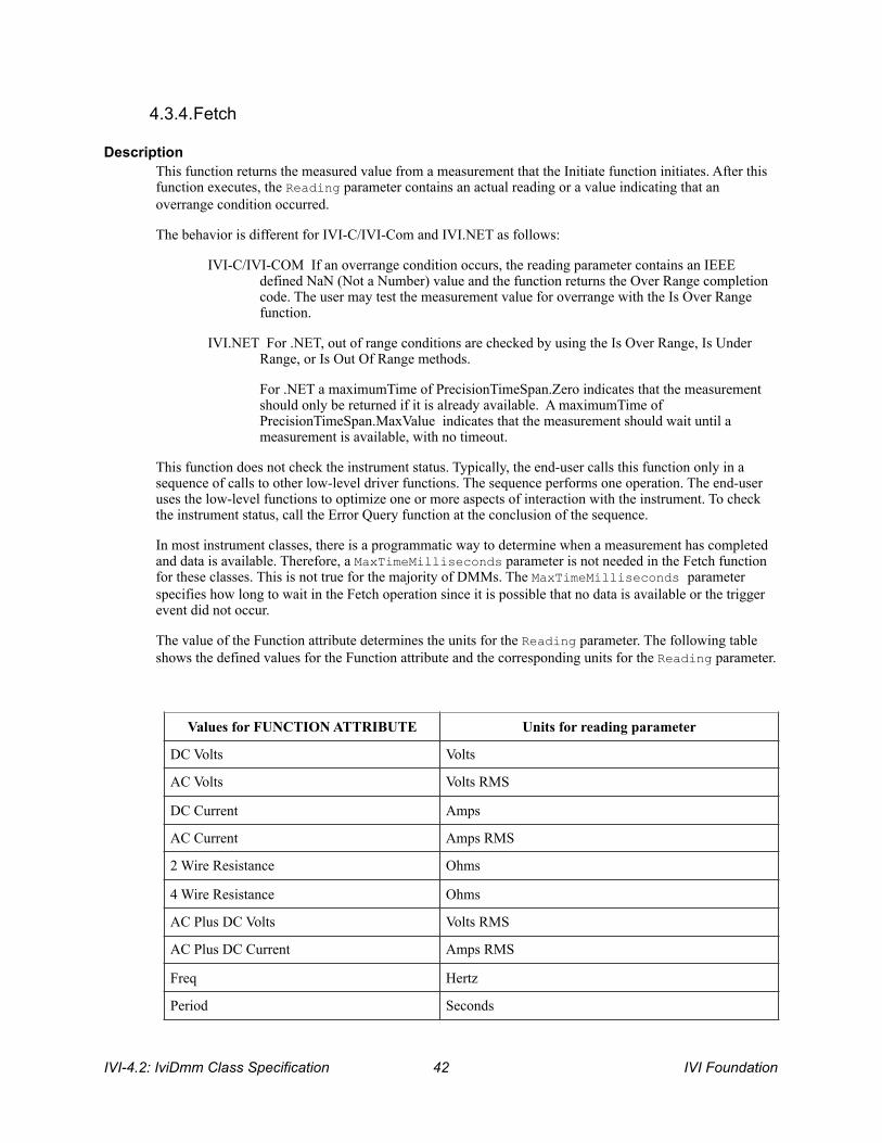
4.3.4.Fetch
Description This function returns the measured value from a measurement that the Initiate function initiates. After this function executes, the Reading parameter contains an actual reading or a value indicating that an overrange condition occurred.
The behavior is different for IVI-C/IVI-Com and IVI.NET as follows:
IVI-C/IVI-COM If an overrange condition occurs, the reading parameter contains an IEEE defined NaN (Not a Number) value and the function returns the Over Range completion code. The user may test the measurement value for overrange with the Is Over Range function.
IVI.NET For .NET, out of range conditions are checked by using the Is Over Range, Is Under Range, or Is Out Of Range methods.
For .NET a maximumTime of PrecisionTimeSpan.Zero indicates that the measurement should only be returned if it is already available. A maximumTime of PrecisionTimeSpan.MaxValue indicates that the measurement should wait until a measurement is available, with no timeout.
This function does not check the instrument status. Typically, the end-user calls this function only in a sequence of calls to other low-level driver functions. The sequence performs one operation. The end-user uses the low-level functions to optimize one or more aspects of interaction with the instrument. To check the instrument status, call the Error Query function at the conclusion of the sequence.
In most instrument classes, there is a programmatic way to determine when a measurement has completed and data is available. Therefore, a MaxTimeMilliseconds parameter is not needed in the Fetch function for these classes. This is not true for the majority of DMMs. The MaxTimeMilliseconds parameter specifies how long to wait in the Fetch operation since it is possible that no data is available or the trigger event did not occur.
The value of the Function attribute determines the units for the Reading parameter. The following table shows the defined values for the Function attribute and the corresponding units for the Reading parameter.
Values for FUNCTION ATTRIBUTE Units for reading parameter
DC Volts Volts
AC Volts Volts RMS
DC Current Amps
AC Current Amps RMS
2 Wire Resistance Ohms
4 Wire Resistance Ohms
AC Plus DC Volts Volts RMS
AC Plus DC Current Amps RMS
Freq Hertz
Period Seconds
IVI-4.2: IviDmm Class Specification ! IVI Foundation 42

This function is not guaranteed to return valid data if the user performs other operations on the instrument after the call to Initiate and prior to calling this function. This includes other calls to Fetch.
.NET Method Prototype Double Measurement.Fetch(PrecisionTimeSpan maximumTime);
COM Method Prototype HRESULT Measurement.Fetch([in] LONG MaxTimeMilliseconds, [out, retval] DOUBLE* Reading);
C Prototype ViStatus IviDmm_Fetch (ViSession Vi, ViInt32 MaxTimeMilliseconds, ViReal64 *Reading);
Parameters
Defined Values for the MaxTimeMilliseconds Parameter (C and COM)
Temperature Degrees Celsius
Inputs Description Base Type
Vi Instrument handle ViSession
MaxTimeMilliseconds (C/COM)
Specifies the maximum length of time allowed for the function to complete in milliseconds.
ViInt32
maximumTime (.NET)
Specifies the maximum length of time for the function to complete before failing.
PrecisionTimeSpan
Outputs Description Base Type
Reading (C/COM) Measurement value. ViReal64
Return value (.NET)
Measurement value. ViReal64
Name Description
Language Identifier
Max Time Immediate
The function returns immediately. If no valid measurement value exists, the function returns an error.
C IVIDMM_VAL_MAX_TIME_IMMEDIATE
COM IviDmmMaxTimeImmediate
Max Time Infinite The function waits indefinitely for the measurement to complete.
C IVIDMM_VAL_MAX_TIME_INFINITE
IVI Foundation ! IVI-4.2: IviDmm Class Specification 43

Defined Values for the MaximumTime Parameter (.NET)
Return Values (C/COM) The IVI-3.2: Inherent Capabilities Specification defines general status codes that this function can return. The table below specifies additional class-defined status codes for this function.
.NET Exceptions The IVI-3.2: Inherent Capabilities Specification defines general exceptions that may be thrown, and warning events that may be raised, by this method.
Note that the .NET MaxTimeExceededException is defined in IVI-3.2: Inherent Capabilities Specification.
Compliance Notes An IviDmm specific driver is not required to implement the Max Time Immediate or the Max Time Infinite defined values for the MaxTimeMilliseconds parameter to be compliant with the IviDmmBase Capability group.
COM IviDmmMaxTimeInfinite
Name Description
Language Identifier
Zero The function returns immediately. If no valid measurement value exists, the function returns an error.
.NET PrecisionTimeSpan.Zero
MaxValue The function waits indefinitely for the measurement to complete.
.NET PrecisionTimeSpan.MaxValue
Completion Codes Description
Over Range Overrange warning
Max Time Exceeded Max time exceeded before the operation completed
IVI-4.2: IviDmm Class Specification ! IVI Foundation 44

4.3.5.Initiate
Description This function initiates a measurement. When this function executes, the DMM leaves the idle state and waits for a trigger.
This function does not check the instrument status. Typically, the end-user calls this function only in a sequence of calls to other low-level driver functions. The sequence performs one operation. The end-user uses the low-level functions to optimize one or more aspects of interaction with the instrument. To check the instrument status, call the Error Query function at the conclusion of the sequence.
.NET Method Prototype Void Measurement.Initiate();
COM Method Prototype HRESULT Measurement.Initiate();
C Prototype ViStatus IviDmm_Initiate (ViSession Vi);
Parameters
Return Values (C/COM) The IVI-3.2: Inherent Capabilities Specification defines general status codes that this function can return.
.NET Exceptions The IVI-3.2: Inherent Capabilities Specification defines general exceptions that may be thrown, and warning events that may be raised, by this method.
Inputs Description Base Type
Vi Instrument handle ViSession
IVI Foundation ! IVI-4.2: IviDmm Class Specification 45

4.3.6.Is Out Of Range (IVI.NET Only)
Description This function takes a measurement value obtained from one of the Read or Fetch functions and determines if the value is a valid measurement value or a value indicating that an out of range condition occurred. Out of range returns true if and only if the measurement value is either over range or under range.
.NET Method Prototype Boolean Measurement.IsOutOfRange(Double MeasurementValue);
COM Method Prototype N/A
C Prototype N/A
Parameters
Return Values (C/COM)) The IVI-3.2: Inherent Capabilities Specification defines general status codes that this function can return.
.NET Exceptions The IVI-3.2: Inherent Capabilities Specification defines general exceptions that may be thrown, and warning events that may be raised, by this method.
Inputs Description Base Type
Vi Instrument handle ViSession
MeasurementValue Pass the measurement value you obtain from one of the Read or Fetch functions.
ViReal64
Outputs Description Base Type
Return value (.NET)
Returns whether the measurementValue is a valid measurement or a value indicating that the DMM encountered an out of range condition. Valid Return Values: True - The measurementValue indicates that an out of range condition occurred. False - The measurementValue is a valid measurement.
ViBoolean
IVI-4.2: IviDmm Class Specification ! IVI Foundation 46

4.3.7.Is Over Range
Description This function takes a measurement value obtained from one of the Read or Fetch functions and determines if the value is a valid measurement value or a value indicating that an overrange condition occurred.
.NET Method Prototype Boolean Measurement.IsOverRange(Double MeasurementValue);
COM Method Prototype HRESULT Measurement.IsOverRange([in] DOUBLE MeasurementValue, [out, retval] VARIANT_BOOL* IsOver);
C Prototype ViStatus IviDmm_IsOverRange (ViSession Vi, ViReal64 MeasurementValue, ViBoolean *IsOverRange);
Parameters
Return Values (C/COM)) The IVI-3.2: Inherent Capabilities Specification defines general status codes that this function can return.
.NET Exceptions The IVI-3.2: Inherent Capabilities Specification defines general exceptions that may be thrown, and warning events that may be raised, by this method.
Inputs Description Base Type
Vi Instrument handle ViSession
MeasurementValue Pass the measurement value you obtain from one of the Read or Fetch functions.
ViReal64
Outputs Description Base Type
IsOverRange (C/COM) Return value (.NET)
Returns whether the measurementValue is a valid measurement or a value indicating that the DMM encountered an over range condition. Valid Return Values: True - The measurementValue indicates that an overrange condition occurred. False - The measurementValue is a valid measurement.
ViBoolean
IVI Foundation ! IVI-4.2: IviDmm Class Specification 47
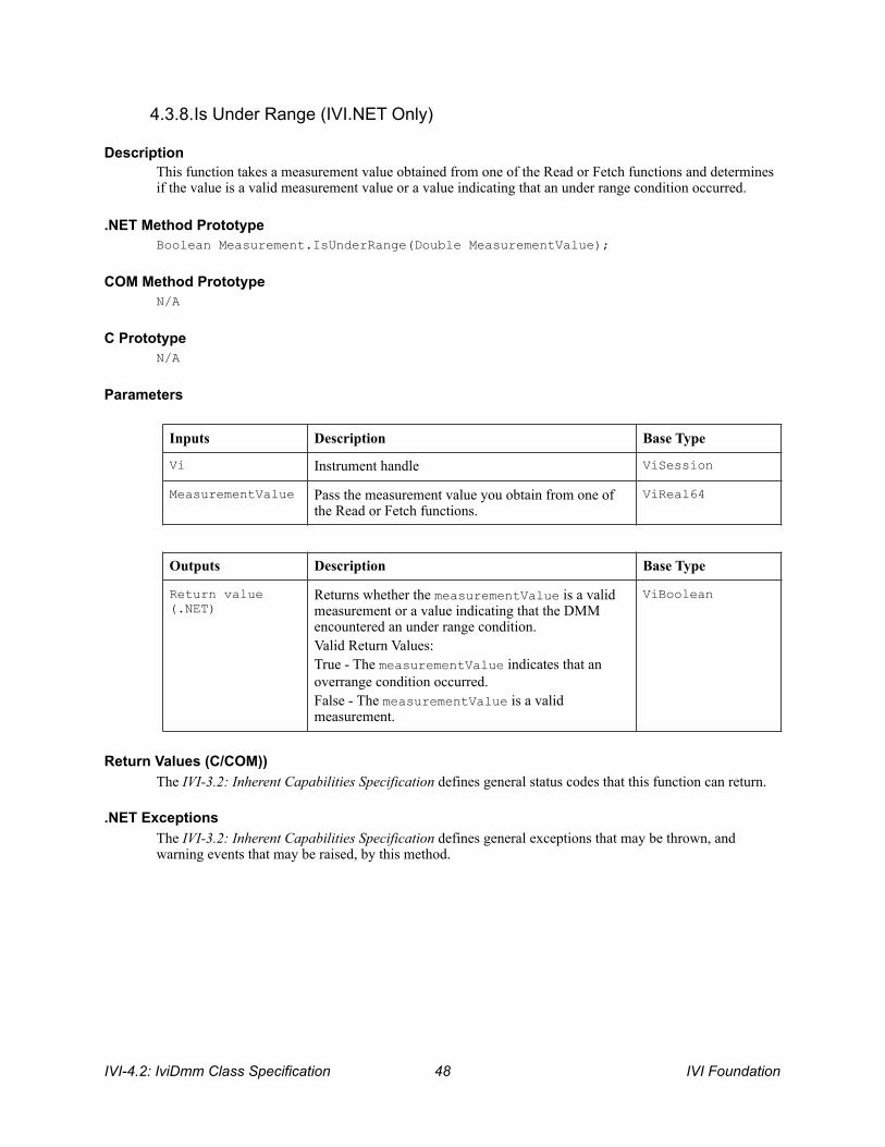
4.3.8.Is Under Range (IVI.NET Only)
Description This function takes a measurement value obtained from one of the Read or Fetch functions and determines if the value is a valid measurement value or a value indicating that an under range condition occurred.
.NET Method Prototype Boolean Measurement.IsUnderRange(Double MeasurementValue);
COM Method Prototype N/A
C Prototype N/A
Parameters
Return Values (C/COM)) The IVI-3.2: Inherent Capabilities Specification defines general status codes that this function can return.
.NET Exceptions The IVI-3.2: Inherent Capabilities Specification defines general exceptions that may be thrown, and warning events that may be raised, by this method.
Inputs Description Base Type
Vi Instrument handle ViSession
MeasurementValue Pass the measurement value you obtain from one of the Read or Fetch functions.
ViReal64
Outputs Description Base Type
Return value (.NET)
Returns whether the measurementValue is a valid measurement or a value indicating that the DMM encountered an under range condition. Valid Return Values: True - The measurementValue indicates that an overrange condition occurred. False - The measurementValue is a valid measurement.
ViBoolean
IVI-4.2: IviDmm Class Specification ! IVI Foundation 48

4.3.9.Read
Description This function initiates a measurement, waits until the DMM has returned to the idle state, and returns the measured value.
The behavior is different for IVI-C/IVI-COM and IVI.NET as follows:
IVI-C/IVI-COM, after this function executes, the Reading parameter contains an actual reading or a value indicating that an overrange condition occurred. If an overrange condition occurs, the Reading parameter contains an IEEE 754 defined NaN (Not a Number) value and the function returns Over Range. The end-user may test the measurement value for overrange with the Is Over Range function.
IVI.NET For .NET, out of range conditions are checked by using the Is Over Range, Is Under Range, or Is Out Of Range methods.
The value of the Function attribute determines the units for the Reading parameter. Refer to Section 4.3.3, Fetch, for more details.
.NET Method Prototype Double Measurement.Read(PrecisionTimeSpan maximumTime);
COM Method Prototype HRESULT Measurement.Read([in] LONG MaxTimeMilliseconds, [out, retval] DOUBLE* Reading);
C Prototype ViStatus IviDmm_Read (ViSession Vi, ViInt32 MaxTimeMilliseconds, ViReal64 *Reading);
Parameters
Defined Values for the MaxTimeMilliseconds Parameter
Inputs Description Base Type
Vi Instrument handle ViSession
MaxTimeMilliseconds (C/COM)
Specifies the maximum length of time allowed for the function to complete in milliseconds.
ViInt32
maximumTime (.NET) Specifies the maximum length of time allowed for the function to complete.
PrecisionTimeSpan
Outputs Description Base Type
Reading (C/COM) Measurement value. ViReal64
Return value (.NET)
Measurement value. ViReal64
IVI Foundation ! IVI-4.2: IviDmm Class Specification 49

Defined Values for the MaximumTime Parameter (.NET)
Return Values (C/COM) The IVI-3.2: Inherent Capabilities Specification defines general status codes that this function can return. The table below specifies additional class-defined status codes for this function.
.NET Exceptions The IVI-3.2: Inherent Capabilities Specification defines general exceptions that may be thrown, and warning events that may be raised, by this method.
Note that the .NET MaxTimeExceededException is defined in IVI-3.2: Inherent Capabilities Specification.
Compliance Notes An IviDmm specific driver is not required to implement the Max Time Immediate or the Max Time Infinite defined values for the MaxTimeMilliseconds parameter to be compliant with the IviDmmBase extension group.
Name Description
Language Identifier
Max Time Immediate
The function returns immediately. If no valid measurement value exists, the function returns an error.
C IVIDMM_VAL_MAX_TIME_IMMEDIATE
COM IviDmmMaxTimeImmediate
Max Time Infinite The function waits indefinitely for the measurement to complete.
C IVIDMM_VAL_MAX_TIME_INFINITE
COM IviDmmMaxTimeInfinite
Name Description
Language Identifier
Zero The function returns immediately. If no valid measurement value exists, the function returns an error.
.NET PrecisionTimeSpan.Zero
MaxValue The function waits indefinitely for the measurement to complete.
.NET PrecisionTimeSpan.MaxValue
Completion Codes Description
Over Range Overrange warning
Max Time Exceeded Max time exceeded before the operation completed
IVI-4.2: IviDmm Class Specification ! IVI Foundation 50

4.4.IviDmmBase Behavior Model The following behavior model shows the relationship between the IviDmmBase capability group and DMM behavior.
!
Figure 4-1. IviDmm Behavior Model
The main state in the IviDmm Class is the Idle state. The DMM enters the Idle state as the result of being “powered-on”, successfully completing a measurement, or by being aborted from a previous measurement by the user with the Abort function. Typically, the user configures the DMM while it is in the Idle state. IviDmm attributes can be configured individually with the Set Attribute function or with the high-level Configure function.
The Read and Initiate functions cause the DMM to leave the Idle state and transition to the Wait-For-Trigger state. The Read function does not return until the measurement process is complete and the DMM returns to the Idle state. The Initiate function returns as soon as the DMM leaves the Idle state.
The DMM leaves the Wait-For-Trigger state when it receives a trigger event. The type of trigger event is specified by the attribute Trigger Source.
After the specified trigger event occurs, the DMM waits the amount of time specified by the attribute Trigger Delay and then takes a measurement. The type of measurement is specified by the attributes Function, Range, and Resolution Absolute.
If the Function attribute is set to a value that requires an extension capability group, the attributes of that capability group further configure the measurement.
Wait-For- Trigger State
Initiate Triggering Read Initiate
Trigger Source
Idle State
Take Measurement
Abort
Measurement Complete
Function Range Resolution Absolute
Delay Trigger Delay
IVI Foundation ! IVI-4.2: IviDmm Class Specification 51

After the measurement is taken, the DMM (if it is capable of doing so) generates the Measurement Complete signal and returns to the Idle state.
The IviDmmBase capability group does not require that a DMM be able to generate a Measurement Complete signal. The IviDmmMultiPoint capability group defines how the Measurement Complete signal is configured. The Measurement Complete signal is presented in the IviDmm behavior model diagram to define when the signal is generated as most DMMs generate this signal but may not be able to configure it.
The Fetch function is used to retrieve measurements that were initiated by the Initiate function. The measurement data returned from the Read and Fetch functions is acquired after the DMM has left the Wait-For-Trigger state.
IVI-4.2: IviDmm Class Specification ! IVI Foundation 52
5.IviDmmACMeasurement Extension Group
5.1.IviDmmACMeasurement Overview The IviDmmACMeasurement extension group supports DMMs that take AC voltage or AC current measurements. It defines attributes that configure additional settings for AC measurements. These attributes are the minimum and maximum frequency components of the input signal. This extension group also defines functions that configure these attributes.
5.2.IviDmmACMeasurement Attributes The IviDmmACMeasurement extension group defines the following attributes: • AC Max Freq • AC Min Freq
This section describes the behavior and requirements of each attribute. The actual value for each attribute ID is defined in Section 18, IviDmm Attribute ID Definitions.
IVI Foundation ! IVI-4.2: IviDmm Class Specification 53

5.2.1.AC Max Freq
.NET Property Name AC.FrequencyMax
COM Property Name AC.FrequencyMax
C Constant Name IVIDMM_ATTR_AC_MAX_FREQ
Description Specifies the maximum frequency component of the input signal for AC measurements. The value of this attribute affects instrument behavior only when the Function attribute is set to an AC voltage or AC current measurement.
.NET Exceptions The IVI-3.2: Inherent Capabilities Specification defines general exceptions that may be thrown, and warning events that may be raised, by this property.
Data Type Access Applies To Coercion High Level Functions
ViReal64 R/W N/A Up Configure AC Bandwidth
IVI-4.2: IviDmm Class Specification ! IVI Foundation 54

5.2.2.AC Min Freq
.NET Property Name AC.FrequencyMin
COM Property Name AC.FrequencyMin
C Constant Name IVIDMM_ATTR_AC_MIN_FREQ
Description Specifies the minimum frequency component of the input signal for AC measurements. The value of this attribute affects instrument behavior only when the Function attribute is set to an AC voltage or AC current measurement.
.NET Exceptions The IVI-3.2: Inherent Capabilities Specification defines general exceptions that may be thrown, and warning events that may be raised, by this property.
Data Type Access Applies To Coercion High Level Functions
ViReal64 R/W N/A Down Configure AC Bandwidth
IVI Foundation ! IVI-4.2: IviDmm Class Specification 55
5.3.IviDmmACMeasurement Functions The IviDmmACMeasurement extension group defines the following function: • Configure AC Bandwidth
This section describes the behavior and requirements of this function.
IVI-4.2: IviDmm Class Specification ! IVI Foundation 56

5.3.1.Configure AC Bandwidth
Description This function configures additional parameters for DMMs that take AC voltage or AC current measurements. These attributes are the AC minimum and maximum frequency.
.NET Method Prototype void AC.ConfigureBandwidth (Double MinFreq, Double MaxFreq);
COM Method Prototype HRESULT AC.ConfigureBandwidth ([in] DOUBLE MinFreq, [in] DOUBLE MaxFreq);
C Prototype ViStatus IviDmm_ConfigureACBandwidth (ViSession Vi, ViReal64 MinFreq, ViReal64 MaxFreq);
Parameters
Return Values (C/COM) The IVI-3.2: Inherent Capabilities Specification defines general status codes that this function can return.
.NET Exceptions The IVI-3.2: Inherent Capabilities Specification defines general exceptions that may be thrown, and warning events that may be raised, by this method.
Inputs Description Base Type
Vi Instrument handle ViSession
MinFreq Specifies the AC minimum frequency. The driver uses this value to set the AC Min Freq attribute. See the attribute description for more details.
ViReal64
MaxFreq Specifies the AC maximum frequency. The driver uses this value to set the AC Max Freq attribute. See the attribute description for more details.
ViReal64
IVI Foundation ! IVI-4.2: IviDmm Class Specification 57

5.4.IviDmmACMeasurement Behavior Model The IviDmmACMeasurement extension group follows the same behavior model as the IviDmmBase capability group described in Section 4.4, IviDmmBase Behavior Model.
5.5.IviDmmACMeasurement Compliance Notes 1. IviDmm specific drivers that implement this extension group shall implement at least one of the
following values for the Function attribute in the IviDmmBase capability group: • AC Volts • AC Current • AC Plus DC Volts • AC Plus DC Volts
IVI-4.2: IviDmm Class Specification ! IVI Foundation 58

6.IviDmmFrequencyMeasurement Extension Group
6.1.IviDmmFrequencyMeasurement Overview The IviDmmFrequencyMeasurement extension group supports DMMs that take frequency measurements. It defines attributes that are required to configure additional parameters needed for frequency measurements.
6.2.IviDmmFrequencyMeasurement Attributes The IviDmmFrequencyMeasurement extension group defines the following attribute: • Frequency Voltage Range
This section describes the behavior and requirements of this attribute. The actual value for this attribute ID is defined in Section 18, IviDmm Attribute ID Definitions.
IVI Foundation ! IVI-4.2: IviDmm Class Specification 59

6.2.1.Frequency Voltage Range
.NET Property Name Frequency.VoltageRange
COM Property Name Frequency.VoltageRange
C Constant Name IVIDMM_ATTR_FREQ_VOLTAGE_RANGE
Description Specifies the expected maximum amplitude of the input signal for frequency and period measurements.
The behavior is different for IVI-C/IVI-COM and IVI.NET as follows: IVI-C/IVI-COM Positive values represent the manual range. Negative values represent the Auto
Range mode.
IVI.NET Specifies the frequency voltage range. Querying this value will return the frequency voltage range corresponding to the maximum input value based on the rest of the instrument configuration. Setting this property sets the Frequency Voltage Auto Range attribute to Off.
The value of this attribute affects instrument behavior only when the Function attribute is set to a frequency or period measurement.
The units are specified in Volts RMS.
Defined Values There are no defined values for IVI.NET
Data Type Access Applies To Coercion High Level Functions
ViReal64 R/W N/A Up Configure Frequency Voltage Range
Name Description
Language Identifier
Auto Range On Sets the DMM to calculate the frequency voltage range before each measurement automatically. Setting this attribute to a manual range or to Auto Range Off disables auto-ranging.
C IVIDMM_VAL_AUTO_RANGE_ON
COM IviDmmFrequencyVoltageRangeAutoRangeOn
Auto Range Off Disables auto-ranging. Further queries of this attribute return the actual frequency voltage range.
C IVIDMM_VAL_AUTO_RANGE_OFF
IVI-4.2: IviDmm Class Specification ! IVI Foundation 60
.NET Exceptions The IVI-3.2: Inherent Capabilities Specification defines general exceptions that may be thrown, and warning events that may be raised, by this property.
Compliance Notes 1. If an IVI-C specific driver defines additional values for this attribute, the magnitude of the actual
values must be greater than or equal to Frequency Volt Range Specific Extension Base. 2. If an IVI-C class driver defines additional values for this attribute, the magnitude of the actual values
must be greater than or equal to Frequency Volt Range Class Extension Base and less than Frequency Volt Range Specific Extension Base.
3. When an IVI-COM specific driver implements this attribute with additional elements in its instrument specific interfaces, it is recommended that the actual values of the additional elements be greater than or equal to Frequency Volt Range Specific Extension Base.
See Section 19, Attribute Value Definitions, for the definitions of Frequency Volt Range Specific Extension Base and Frequency Volt Range Class Extension Base.
COM IviDmmFrequencyVoltageRangeAutoRangeOff
IVI Foundation ! IVI-4.2: IviDmm Class Specification 61

6.2.2.Frequency Voltage Range Auto (IVI.NET Only)
.NET Property Name Frequency.VoltageRangeAuto
COM Property Name N/A
C Constant Name N/A
Description
If this attribute is set to True, the driver sets the DMM to calculate the frequency voltage range before each measurement automatically.
If this attribute is set to False, the driver sets the frequency voltage range to the value it most recently set or calculated.
The actual voltage range the DMM is currently using can be determined from the Frequency Voltage Range attribute in the IviDmmFrequencyMeasurement extension group.
Setting the Frequency Voltage Range attribute also sets the Frequency Voltage Range Auto attribute to false.
Note that IVI-COM and IVI-C achieve this behavior by setting the Frequency Voltage Range attribute to defined values.
.NET Exceptions The IVI-3.2: Inherent Capabilities Specification defines general exceptions that may be thrown, and warning events that may be raised, by this property.
Note that the .NET Auto Once Not Supported exception is defined in IVI-3.2: Inherent Capabilities Specification.
Data Type Access Applies To Coercion High Level Functions
ViBoolean R/W N/A N/A N/A
IVI-4.2: IviDmm Class Specification ! IVI Foundation 62

6.3.IviDmmFrequencyMeasurement Functions The IviDmmFrequencyMeasurement extension group defines the following function: • Configure Frequency Voltage Range (IVI-C only)
This section describes the behavior and requirements of this function.
IVI Foundation ! IVI-4.2: IviDmm Class Specification 63
6.3.1.Configure Frequency Voltage Range (IVI-C Only)
Description This function configures the frequency voltage range of the DMM.
.NET Method Prototype N/A
(use the Frequency.VoltageRange and Frequency.VoltageAutoRange properties)
COM Method Prototype N/A
(use the Frequency.VoltageRange property)
C Prototype ViStatus IviDmm_ConfigureFrequencyVoltageRange (ViSession Vi, ViReal64 FrequencyVoltageRange);
Parameters
Return Values (C) The IVI-3.2: Inherent Capabilities Specification defines general status codes that this function can return.
Inputs Description Base Type
Vi Instrument handle ViSession
FrequencyVoltageRange Specifies the expected maximum value of the input signal. The driver uses this value to set the Frequency Voltage Range attribute. See the attribute description for more details.
ViReal64
IVI-4.2: IviDmm Class Specification ! IVI Foundation 64

6.4.IviDmmFrequencyMeasurement Behavior Model The IviDmmFrequencyMeasurement extension group follows the same behavior model as the IviDmmBase capability group described in Section 4.4, IviDmmBase Behavior Model.
6.5.IviDmmFrequencyMeasurement Compliance Notes 1. IviDmm specific drivers that implement this extension group shall implement at least one of the
following values for the Function attribute in the IviDmmBase capability group: • Frequency• Period
IVI Foundation ! IVI-4.2: IviDmm Class Specification 65

7.IviDmmTemperatureMeasurement Extension Group
7.1.IviDmmTemperatureMeasurement Overview The IviDmmTemperatureMeasurement extension group supports DMMs that take temperature measurements with a thermocouple, an RTD, or a thermistor transducer type. This extension group selects the transducer type. Other capability groups further configure temperature settings based on the transducer type.
7.2.IviDmmTemperatureMeasurement Attributes The IviDmmTemperatureMeasurement extension group defines the following attribute: • Temperature Transducer Type
This section describes the behavior and requirements of this attribute. The actual value for the attribute ID is defined in Section 18, IviDmm Attribute ID Definitions.
IVI-4.2: IviDmm Class Specification ! IVI Foundation 66

7.2.1.Temperature Transducer Type
.NET Property Name Temperature.TransducerType
.NET Enumeration Name Temperature.TransducerType
COM Property Name Temperature.TransducerType
COM Enumeration Name IviDmmTransducerTypeEnum
C Constant Name IVIDMM_ATTR_TEMP_TRANSDUCER_TYPE
Description Specifies the device used to measure the temperature. The value of this attribute affects instrument behavior only when the Function attribute is set to a temperature measurement.
Data Type Access Applies To Coercion High Level Functions
ViInt32 R/W N/A None Configure Transducer Type
IVI Foundation ! IVI-4.2: IviDmm Class Specification 67

Defined Values
.NET Exceptions The IVI-3.2: Inherent Capabilities Specification defines general exceptions that may be thrown, and warning events that may be raised, by this property.
Compliance Notes If an IviDmm specific driver implements any of the defined values in the following table, it shall also implement the corresponding capability group:
Name Description
Language Identifier
Thermocouple Sets the DMM to measure temperature using a thermocouple. Use the IviDmmThermocouple extension group to configure additional settings for this transducer type.
.NET TransducerType.Thermocouple
C IVIDMM_VAL_THERMOCOUPLE
COM IviDmmTransducerTypeThermocouple
Thermistor Sets the DMM to measure temperature using a thermistor. Use the IviDmmThermistor extension group to configure additional settings for this transducer type.
.NET TransducerType.Thermistor
C IVIDMM_VAL_THERMISTOR
COM IviDmmTransducerTypeThermistor
2 Wire RTD Sets the DMM to measure temperature using a 2-wire temperature resistance device. Use the IviDmmResistanceTemperatureDevice extension group to configure additional settings for this transducer type.
.NET TransducerType.TwoWireRtd
C IVIDMM_VAL_2_WIRE_RTD
COM IviDmmTransducerType2WireRtd
4 Wire RTD Sets the DMM to measure temperature using a 4-wire temperature resistance device. Use the IviDmmResistanceTemperatureDevice extension group to configure additional settings for this transducer type.
.NET TransducerType.FourWireRtd
C IVIDMM_VAL_4_WIRE_RTD
COM IviDmmTransducerType4WireRtd
Value Required Capability Group
Thermocouple IviDmmThermocouple
IVI-4.2: IviDmm Class Specification ! IVI Foundation 68
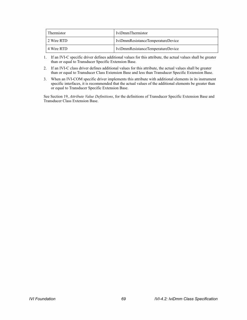
1. If an IVI-C specific driver defines additional values for this attribute, the actual values shall be greater than or equal to Transducer Specific Extension Base.
2. If an IVI-C class driver defines additional values for this attribute, the actual values shall be greater than or equal to Transducer Class Extension Base and less than Transducer Specific Extension Base.
3. When an IVI-COM specific driver implements this attribute with additional elements in its instrument specific interfaces, it is recommended that the actual values of the additional elements be greater than or equal to Transducer Specific Extension Base.
See Section 19, Attribute Value Definitions, for the definitions of Transducer Specific Extension Base and Transducer Class Extension Base.
Thermistor IviDmmThermistor
2 Wire RTD IviDmmResistanceTemperatureDevice
4 Wire RTD IviDmmResistanceTemperatureDevice
IVI Foundation ! IVI-4.2: IviDmm Class Specification 69

7.3.IviDmmTemperatureMeasurement Functions The IviDmmTemperatureMeasurement extension group defines the following function: • Configure Transducer Type (IVI-C only)
This section describes the behavior and requirements of this function.
IVI-4.2: IviDmm Class Specification ! IVI Foundation 70
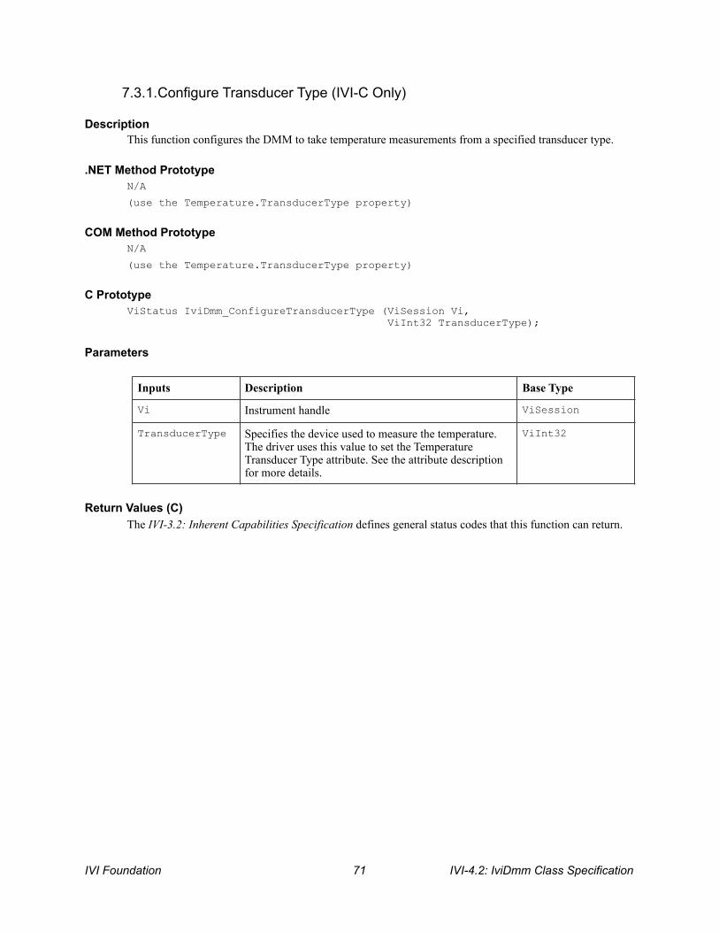
7.3.1.Configure Transducer Type (IVI-C Only)
Description This function configures the DMM to take temperature measurements from a specified transducer type.
.NET Method Prototype N/A
(use the Temperature.TransducerType property)
COM Method Prototype N/A
(use the Temperature.TransducerType property)
C Prototype ViStatus IviDmm_ConfigureTransducerType (ViSession Vi, ViInt32 TransducerType);
Parameters
Return Values (C) The IVI-3.2: Inherent Capabilities Specification defines general status codes that this function can return.
Inputs Description Base Type
Vi Instrument handle ViSession
TransducerType Specifies the device used to measure the temperature. The driver uses this value to set the Temperature Transducer Type attribute. See the attribute description for more details.
ViInt32
IVI Foundation ! IVI-4.2: IviDmm Class Specification 71
7.4.IviDmmTemperatureMeasurement Behavior Model The IviDmmTemperatureMeasurement extension group follows the same behavior model as the IviDmmBase capability group described in Section 4.4, IviDmmBase Behavior Model.
7.5.IviDmmTemperatureMeasurement Compliance Notes 1. IviDmm specific drivers that implement this extension group shall implement the Temperature value
for the Function attribute in the IviDmmBase capability group.
IVI-4.2: IviDmm Class Specification ! IVI Foundation 72

8.IviDmmThermocouple Extension Group
8.1.IviDmmThermocouple Extension Group Overview The IviDmmThermocouple extension group supports DMMs that take temperature measurements using a thermocouple transducer type.
8.2.IviDmmThermocouple Attributes The IviDmmThermocouple extension group defines the following attributes: • Thermocouple Fixed Reference Junction • Thermocouple Reference Junction Type • Thermocouple Type
This section describes the behavior and requirements of each attribute. The actual value for each attribute ID is defined in Section 18, IviDmm Attribute ID Definitions.
IVI Foundation ! IVI-4.2: IviDmm Class Specification 73

8.2.1.Thermocouple Fixed Reference Junction
.NET Property Name Temperature.Thermocouple.FixedReferenceJunction
COM Property Name Temperature.Thermocouple.FixedRefJunction
C Constant Name IVIDMM_ATTR_TEMP_TC_FIXED_REF_JUNC
Description Specifies the external reference junction temperature when a fixed reference junction type thermocouple is used to take the temperature measurement. The temperature is specified in degrees Celsius.
This attribute may also be used to specify the thermocouple junction temperature of an instrument that does not have an internal temperature sensor.
The value of this attribute affects instrument behavior only when the Thermocouple Reference Junction Type is set to Temperature Reference Junction Fixed.
.NET Exceptions The IVI-3.2: Inherent Capabilities Specification defines general exceptions that may be thrown, and warning events that may be raised, by this property.
Compliance Notes IviDmm specific drivers that implement this attribute shall implement the Temperature Reference Junction Fixed defined value for the Thermocouple Reference Junction Type attribute.
Data Type Access Applies To Coercion High Level Functions
ViReal64 R/W N/A None Configure Fixed Reference Junction
IVI-4.2: IviDmm Class Specification ! IVI Foundation 74
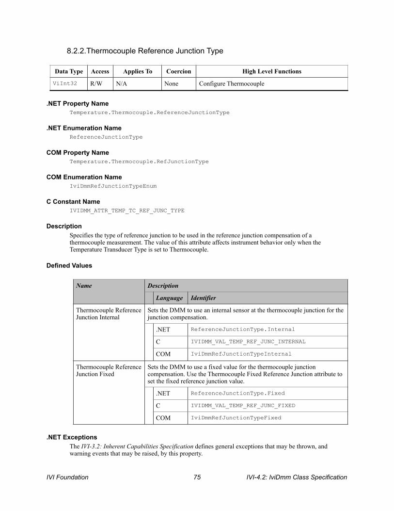
8.2.2.Thermocouple Reference Junction Type
.NET Property Name Temperature.Thermocouple.ReferenceJunctionType
.NET Enumeration Name ReferenceJunctionType
COM Property Name Temperature.Thermocouple.RefJunctionType
COM Enumeration Name IviDmmRefJunctionTypeEnum
C Constant Name IVIDMM_ATTR_TEMP_TC_REF_JUNC_TYPE
Description Specifies the type of reference junction to be used in the reference junction compensation of a thermocouple measurement. The value of this attribute affects instrument behavior only when the Temperature Transducer Type is set to Thermocouple.
Defined Values
.NET Exceptions The IVI-3.2: Inherent Capabilities Specification defines general exceptions that may be thrown, and warning events that may be raised, by this property.
Data Type Access Applies To Coercion High Level Functions
ViInt32 R/W N/A None Configure Thermocouple
Name Description
Language Identifier
Thermocouple Reference Junction Internal
Sets the DMM to use an internal sensor at the thermocouple junction for the junction compensation.
.NET ReferenceJunctionType.Internal
C IVIDMM_VAL_TEMP_REF_JUNC_INTERNAL
COM IviDmmRefJunctionTypeInternal
Thermocouple Reference Junction Fixed
Sets the DMM to use a fixed value for the thermocouple junction compensation. Use the Thermocouple Fixed Reference Junction attribute to set the fixed reference junction value.
.NET ReferenceJunctionType.Fixed
C IVIDMM_VAL_TEMP_REF_JUNC_FIXED
COM IviDmmRefJunctionTypeFixed
IVI Foundation ! IVI-4.2: IviDmm Class Specification 75

Compliance Notes If an IviDmm specific driver implements the Temperature Reference Junction Fixed defined value, then it shall implement the Thermocouple Fixed Reference Junction attribute. 1. If an IVI-C IviDmm specific driver defines additional values for this attribute, the actual values shall
be greater than or equal to Reference Junction Specific Extension Base. 2. If an IVI-C IviDmm class driver defines additional values for this attribute, the actual values shall be
greater than or equal to Reference Junction Class Extension Base and less than Reference Junction Specific Extension Base.
3. When an IVI-COM specific driver implements this attribute with additional elements in its instrument specific interfaces, it is recommended that the actual values of the additional elements be greater than or equal to Reference Junction Specific Extension Base.
See Section 19, Attribute Value Definitions, for the definitions of Reference Junction Specific Extension Base and Reference Junction Class Extension Base.
IVI-4.2: IviDmm Class Specification ! IVI Foundation 76

8.2.3.Thermocouple Type
.NET Property Name Temperature.Thermocouple.Type
.NET Enumeration Name Temperature.ThermocoupleType
COM Property Name Temperature.Thermocouple.Type
COM Enumeration Name IviDmmThermocoupleTypeEnum
C Constant Name IVIDMM_ATTR_TEMP_TC_TYPE
Description Specifies the type of thermocouple used to measure the temperature. The value of this attribute affects instrument behavior only when the Temperature Transducer Type is set to Thermocouple.
Data Type Access Applies To Coercion High Level Functions
ViInt32 R/W N/A None Configure Thermocouple
IVI Foundation ! IVI-4.2: IviDmm Class Specification 77

Defined Values
IVI-4.2: IviDmm Class Specification ! IVI Foundation 78

Name Description
Language Identifier
Thermocouple B Sets the DMM to measure temperature from a B-type thermocouple.
.NET ThermocoupleType.B
C IVIDMM_VAL_TEMP_TC_B
COM IviDmmThermocoupleTypeB
Thermocouple C Sets the DM7M to measure temperature from a C-type thermocouple.
.NET ThermocoupleType.C
C IVIDMM_VAL_TEMP_TC_C
COM IviDmmThermocoupleTypeC
Thermocouple D Sets the DMM to measure temperature from a D-type thermocouple.
.NET ThermocoupleType.D
C IVIDMM_VAL_TEMP_TC_D
COM IviDmmThermocoupleTypeD
Thermocouple E Sets the DMM to measure temperature from an E-type thermocouple.
.NET ThermocoupleType.E
C IVIDMM_VAL_TEMP_TC_E
COM IviDmmThermocoupleTypeE
Thermocouple G Sets the DMM to measure temperature from a G-type thermocouple.
.NET ThermocoupleType.G
C IVIDMM_VAL_TEMP_TC_G
COM IviDmmThermocoupleTypeG
Thermocouple J Sets the DMM to measure temperature from a J-type thermocouple.
.NET ThermocoupleType.J
C IVIDMM_VAL_TEMP_TC_J
COM IviDmmThermocoupleTypeJ
Thermocouple K Sets the DMM to measure temperature from a K-type thermocouple.
.NET ThermocoupleType.K
C IVIDMM_VAL_TEMP_TC_K
IVI Foundation ! IVI-4.2: IviDmm Class Specification 79

.NET Exceptions The IVI-3.2: Inherent Capabilities Specification defines general exceptions that may be thrown, and warning events that may be raised, by this property.
COM IviDmmThermocoupleTypeK
Thermocouple N Sets the DMM to measure temperature from an N-type thermocouple.
.NET ThermocoupleType.N
C IVIDMM_VAL_TEMP_TC_N
COM IviDmmThermocoupleTypeN
Thermocouple R Sets the DMM to measure temperature from an R-type thermocouple.
.NET ThermocoupleType.R
C IVIDMM_VAL_TEMP_TC_R
COM IviDmmThermocoupleTypeR
Thermocouple S Sets the DMM to measure temperature from an S-type thermocouple.
.NET ThermocoupleType.S
C IVIDMM_VAL_TEMP_TC_S
COM IviDmmThermocoupleTypeS
Thermocouple T Sets the DMM to measure temperature from a T-type thermocouple.
.NET ThermocoupleType.T
C IVIDMM_VAL_TEMP_TC_T
COM IviDmmThermocoupleTypeT
Thermocouple U Sets the DMM to measure temperature from a U-type thermocouple.
.NET ThermocoupleType.U
C IVIDMM_VAL_TEMP_TC_U
COM IviDmmThermocoupleTypeU
Thermocouple V Sets the DMM to measure temperature from a V-type thermocouple.
.NET ThermocoupleType.V
C IVIDMM_VAL_TEMP_TC_V
COM IviDmmThermocoupleTypeV
Name Description
Language Identifier
IVI-4.2: IviDmm Class Specification ! IVI Foundation 80
Compliance Notes 1. If an IVI-C IviDmm specific driver defines additional values for this attribute, the actual values must
be greater than or equal to Thermocouple Type Specific Extension Base.
2. If an IVI-C IviDmm class driver defines additional values for this attribute, the actual values must be greater than or equal to Thermocouple Type Class Extension Base and less than Thermocouple Type Specific Extension Base.
3. When an IVI-COM specific driver implements this attribute with additional elements in its instrument specific interfaces, it is recommended that the actual values of the additional elements be greater than or equal to Thermocouple Type Specific Extension Base.
See Section 19, Attribute Value Definitions, for the definitions of Thermocouple Type Specific Extension Base and Thermocouple Type Class Extension Base.
IVI Foundation ! IVI-4.2: IviDmm Class Specification 81

8.3.IviDmmThermocouple Functions The IviDmmTemperatureMeasurement extension group defines the following functions: • Configure Fixed Reference Junction (IVI-C only) • Configure Thermocouple
This section describes the behavior and requirements of each function.
IVI-4.2: IviDmm Class Specification ! IVI Foundation 82
8.3.1.Configure Fixed Reference Junction (IVI-C Only)
Description This function configures the fixed reference junction for a thermocouple with a fixed reference junction type.
.NET Method Prototype N/A
(use the Temperature.Thermocouple.FixedReferenceJunction property)
COM Method Prototype N/A
(use the Temperature.Thermocouple.FixedRefJunction property)
C Prototype ViStatus IviDmm_ConfigureFixedRefJunction (ViSession Vi, ViReal64 FixedRefJunction);
Parameters
Return Values (C) The IVI-3.2: Inherent Capabilities Specification defines general status codes that this function can return.
Compliance Notes The IviDmm specific driver is required to implement this function only if the Thermocouple Reference Junction Type attribute implements the Temperature Reference Junction Fixed defined value.
Inputs Description Base Type
Vi Instrument handle ViSession
FixedRefJunction Specifies the fixed reference junction. The driver uses this value to set the Thermocouple Fixed Reference Junction attribute. See the attribute description for more details.
ViReal64
IVI Foundation ! IVI-4.2: IviDmm Class Specification 83
8.3.2.Configure Thermocouple
Description This function configures the thermocouple type and the reference junction type of the thermocouple for DMMs that take temperature measurements using a thermocouple transducer type.
.NET Method Prototype void Temperature.Thermocouple.Configure( ThermocoupleType type, ReferenceJunctionType referenceJunctionType);
COM Method Prototype HRESULT Temperature.Thermocouple.Configure( [in] IviDmmThermocoupleTypeEnum Type, [in] IviDmmRefJunctionTypeEnum RefJunctionType);
C Prototype ViStatus IviDmm_ConfigureThermocouple (ViSession Vi, ViInt32 ThermocoupleType ViInt32 RefJunctionType);
Parameters
Return Values (C/COM) The IVI-3.2: Inherent Capabilities Specification defines general status codes that this function can return.
.NET Exceptions The IVI-3.2: Inherent Capabilities Specification defines general exceptions that may be thrown, and warning events that may be raised, by this method.
Inputs Description Base Type
Vi Instrument handle ViSession
ThermocoupleType Specifies the type of thermocouple used to measure the temperature. The driver uses this value to set the Thermocouple Type attribute. See the attribute description for more details.
ViInt32
RefJunctionType (C/COM) referenceJunctionType (.NET)
Specifies the type of reference junction to be used. The driver uses this value to set the Thermocouple Reference Junction Type attribute. See the attribute description for more details.
ViInt32
IVI-4.2: IviDmm Class Specification ! IVI Foundation 84
8.4.IviDmmThermocouple Behavior Model The IviDmmThermocouple extension group follows the same behavior model as the IviDmmBase capability group described in Section 4.4, IviDmmBase Behavior Model.
8.5.IviDmmThermocouple Compliance Notes 1. IviDmm specific drivers that implement this extension group shall implement the
IviDmmTemperatureMeasurement extension group.
2. IviDmm specific drivers that implement this extension group shall implement the Thermocouple value for the Temperature Transducer Type attribute in the IviDmmTemperatureMeasurement extension group.
IVI Foundation ! IVI-4.2: IviDmm Class Specification 85

9.IviDmmResistanceTemperatureDevice Extension Group
9.1.IviDmmResistanceTemperatureDevice Extension Group Overview The IviDmmResistanceTemperatureDevice extension group supports DMMs that take temperature measurements using a resistance temperature device (RTD) transducer type.
The IviDmm class assumes that you are using a Platinum Resistance Temperature Device.
9.2.IviDmmResistanceTemperatureDevice Attributes The IviDmmResistanceTemperatureDevice extension group defines the following attributes: • RTD Alpha
• RTD Resistance
This section describes the behavior and requirements of each attribute. The actual value for each attribute ID is defined in Section 18, IviDmm Attribute ID Definitions.
IVI-4.2: IviDmm Class Specification ! IVI Foundation 86
9.2.1.RTD Alpha
.NET Property Name Temperature.Rtd.Alpha
COM Property Name Temperature.RTD.Alpha
C Constant Name IVIDMM_ATTR_TEMP_RTD_ALPHA
Description Specifies the alpha parameter for a resistance temperature device (RTD).
The value of this attribute affects instrument behavior only when the Temperature Transducer Type is set to the 2 Wire RTD or the 4 Wire RTD defined values.
.NET Exceptions The IVI-3.2: Inherent Capabilities Specification defines general exceptions that may be thrown, and warning events that may be raised, by this property.
Data Type Access Applies To Coercion High Level Functions
ViReal64 R/W N/A None Configure RTD
IVI Foundation ! IVI-4.2: IviDmm Class Specification 87

9.2.2.RTD Resistance
.NET Property Name Temperature.Rtd.Resistance
COM Property Name Temperature.RTD.Resistance
C Constant Name IVIDMM_ATTR_TEMP_RTD_RES
Description Specifies the R0 parameter (resistance) for a resistance temperature device (RTD). The RTD resistance is also known as the RTD reference value.
The value of this attribute affects instrument behavior only when the Temperature Transducer Type is set to the RTD defined value.
.NET Exceptions The IVI-3.2: Inherent Capabilities Specification defines general exceptions that may be thrown, and warning events that may be raised, by this property.
Data Type Access Applies To Coercion High Level Functions
ViReal64 R/W N/A None Configure RTD
IVI-4.2: IviDmm Class Specification ! IVI Foundation 88
9.3.IviDmmResistanceTemperatureDevice Functions The IviDmmResistanceTemperatureDevice extension group defines the following function: • Configure RTD
This section describes the behavior and requirements of this function.
IVI Foundation ! IVI-4.2: IviDmm Class Specification 89
9.3.1.Configure RTD
Description
This function configures the alpha and resistance parameters for a resistance temperature device.
.NET Method Prototype void Temperature.Rtd.Configure(Double alpha, Double resistance);
COM Method Prototype HRESULT Temperature.RTD.Configure([in] DOUBLE Alpha, [in] DOUBLE Resistance);
C Prototype ViStatus IviDmm_ConfigureRTD (ViSession Vi, ViReal64 Alpha ViReal64 Resistance);
Parameters
Return Values (C/COM) The IVI-3.2: Inherent Capabilities Specification defines general status codes that this function can return.
.NET Exceptions The IVI-3.2: Inherent Capabilities Specification defines general exceptions that may be thrown, and warning events that may be raised, by this method.
Inputs Description Base Type
Vi Instrument handle ViSession
Alpha Specifies the alpha parameter for an RTD. The driver uses this value to set the Temperature RTD Alpha attribute. See the attribute description for more details.
ViReal64
Resistance Specifies the resistance of the RTD. The driver uses this value to set the Temperature RTD Resistance attribute. See the attribute description for more details.
ViReal64
IVI-4.2: IviDmm Class Specification ! IVI Foundation 90

9.4.IviDmmResistanceTemperatureDevice Behavior Model The IviDmmResistanceTemperatureDevice extension group follows the same behavior model as the IviDmmBase capability group described in Section 4.4, IviDmmBase Behavior Model.
9.5.IviDmmResistanceTemperatureDevice Compliance Notes 1. IviDmm specific drivers that implement this extension group shall implement the
IviDmmTemperatureMeasurement extension group.
2. IviDmm specific drivers that implement this extension group shall implement at least one of the following values for the Temperature Transducer Type attribute in the IviDmmTemperatureMeasurement extension group: • 2 Wire RTD • 4 Wire RTD
IVI Foundation ! IVI-4.2: IviDmm Class Specification 91
10.IviDmmThermistor Extension Group
10.1.IviDmmThermistor Extension Group Overview The IviDmmThermistor extension group supports DMMs that take temperature measurements using a thermistor transducer type.
The IviDmm class assumes that you are using an interchangeable thermistor. Interchangeable thermistors are thermistors that exhibit similar behavior for a given resistance value.
10.2.IviDmmThermistor Attributes The IviDmmThermistor extension group defines the following attribute: • Thermistor Resistance
This section describes the behavior and requirements of this attribute. The actual value for each attribute ID is defined in Section 18, IviDmm Attribute ID Definitions.
IVI-4.2: IviDmm Class Specification ! IVI Foundation 92

10.2.1.Thermistor Resistance
.NET Property Name Temperature.Thermistor.Resistance
COM Property Name Temperature.Thermistor.Resistance
C Constant Name IVIDMM_ATTR_TEMP_THERMISTOR_RES
Description Specifies the resistance of the thermistor in Ohms.
The value of this attribute affects instrument behavior only when the Temperature Transducer Type attribute is set to the Thermistor defined value.
.NET Exceptions The IVI-3.2: Inherent Capabilities Specification defines general exceptions that may be thrown, and warning events that may be raised, by this property.
Data Type Access Applies To Coercion High Level Functions
ViReal64 R/W N/A None Configure Thermistor
IVI Foundation ! IVI-4.2: IviDmm Class Specification 93

10.3.IviDmmThermistor Functions The IviDmmThermistor extension group defines the following function: • Configure Thermistor (IVI-C only)
This section describes the behavior and requirements of this function.
IVI-4.2: IviDmm Class Specification ! IVI Foundation 94

10.3.1.Configure Thermistor (IVI-C Only)
Description This function configures the resistance for a thermistor temperature measurement device.
.NET Method Prototype N/A
(use the Temperature.Thermistor property)
COM Method Prototype N/A
(use the Temperature.Thermistor property)
C Prototype ViStatus IviDmm_ConfigureThermistor (ViSession Vi, ViReal64 Resistance);
Parameters
Return Values (C) The IVI-3.2: Inherent Capabilities Specification defines general status codes that this function can return.
Inputs Description Base Type
Vi Instrument handle ViSession
Resistance Specifies the resistance of the thermistor. The driver uses this value to set the Temperature Thermistor Resistance attribute. See the attribute description for more details.
ViReal64
IVI Foundation ! IVI-4.2: IviDmm Class Specification 95

10.4.IviDmmThermistor Behavior Model The IviDmmThermistor extension group follows the same behavior model as IviDmmBase capability group described in Section 4.4, IviDmmBase Behavior Model.
10.5.IviDmmThermistor Compliance Notes 1. IviDmm specific drivers that implement this extension group shall implement the
IviDmmTemperatureMeasurement extension group.
2. IviDmm specific drivers that implement this extension group shall implement the Thermistor value for the Temperature Transducer Type attribute in the IviDmmTemperatureMeasurement capability group.
IVI-4.2: IviDmm Class Specification ! IVI Foundation 96

11.IviDmmMultiPoint Extension Group
11.1.IviDmmMultiPoint Extension Group Overview The IviDmmMultiPoint extension group defines extensions for DMMs capable of acquiring measurements based on multiple triggers, and acquiring multiple measurements for each trigger.
The IviDmmMultiPoint extension group defines additional attributes such sample count, sample trigger, trigger count, and trigger delay to control “multi-point” DMMs. The IviDmmMultiPoint extension group also adds functions for configuring the DMM as well as starting acquisitions and retrieving multiple measured values.
11.2.IviDmmMultiPoint Attributes The IviDmmBase capability group defines the following attributes: • Measure Complete Destination • Sample Count • Sample Interval • Sample Trigger • Trigger Count
This section describes the behavior and requirements of each attribute. The actual value for each attribute ID is defined in Section 18, IviDmm Attribute ID Definitions.
IVI Foundation ! IVI-4.2: IviDmm Class Specification 97

11.2.1.Measure Complete Destination
.NET Property Name Trigger.MeasurementCompleteDestination
COM Property Name Trigger.MultiPoint.MeasurementComplete
COM Enumeration Name IviDmmMeasCompleteDestEnum
C Constant Name IVIDMM_ATTR_MEAS_COMPLETE_DEST
Description
After each measurement, the DMM generates a measurement-complete signal. This attribute specifies the destination of the measurement-complete signal. This signal is commonly referred to as Voltmeter Complete.
Defined Values
In IVI.NET the measurement complete destination is a string. If an IVI driver supports a measurement complete destination and the measurement complete destination is listed in IVI-3.3 Cross Class Capabilities Specification, Section 3, then the IVI driver shall accept the standard string for that measurement complete destination. This attribute is case insensitive, but case preserving. That is, the setting is case insensitive but when reading it back the programmed case is returned. IVI specific drivers may define new measurement complete destination strings for measurement complete destinations that are not defined by IVI-3.3 Cross Class Capabilities Specification if needed.
Data Type Access Applies To Coercion High Level Functions
ViInt32 (C/COM)
R/W N/A None Configure Measure Complete Destination
ViString (.NET)
R/W N/A None N/A
Name Description
Language Identifier
None The measurement complete signal is not routed.
C IVIDMM_VAL_NONE
COM IviDmmMeasCompleteDestNone
External Routes the measurement complete signal to the external connector.
C IVIDMM_VAL_EXTERNAL
COM IviDmmMeasCompleteDestExternal
TTL0 Routes the measurement complete signal to TTL0.
C IVIDMM_VAL_TTL0
IVI-4.2: IviDmm Class Specification ! IVI Foundation 98

COM IviDmmMeasCompleteDestTTL0
TTL1 Routes the measurement complete signal to TTL1.
C IVIDMM_VAL_TTL1
COM IviDmmMeasCompleteDestTTL1
TTL2 Routes the measurement complete signal to TTL2.
C IVIDMM_VAL_TTL2
COM IviDmmMeasCompleteDestTTL2
TTL3 Routes the measurement complete signal to TTL3.
C IVIDMM_VAL_TTL3
COM IviDmmMeasCompleteDestTTL3
TTL4 Routes the measurement complete signal to TTL4.
C IVIDMM_VAL_TTL4
COM IviDmmMeasCompleteDestTTL4
TTL5 Routes the measurement complete signal to TTL5.
C IVIDMM_VAL_TTL5
COM IviDmmMeasCompleteDestTTL5
TTL6 Routes the measurement complete signal to TTL6.
C IVIDMM_VAL_TTL6
COM IviDmmMeasCompleteDestTTL6
TTL7 Routes the measurement complete signal to TTL7.
C IVIDMM_VAL_TTL7
COM IviDmmMeasCompleteDestTTL7
ECL0 Routes the measurement complete signal to ECL0.
C IVIDMM_VAL_ECL0
COM IviDmmMeasCompleteDestECL0
ECL1 Routes the measurement complete signal to ECL1.
C IVIDMM_VAL_ECL1
COM IviDmmMeasCompleteDestECL1
PXI Star Routes the measurement complete signal to the PXI Star trigger bus.
C IVIDMM_VAL_PXI_STAR
COM IviDmmMeasCompleteDestPXIStar
Name Description
Language Identifier
IVI Foundation ! IVI-4.2: IviDmm Class Specification 99
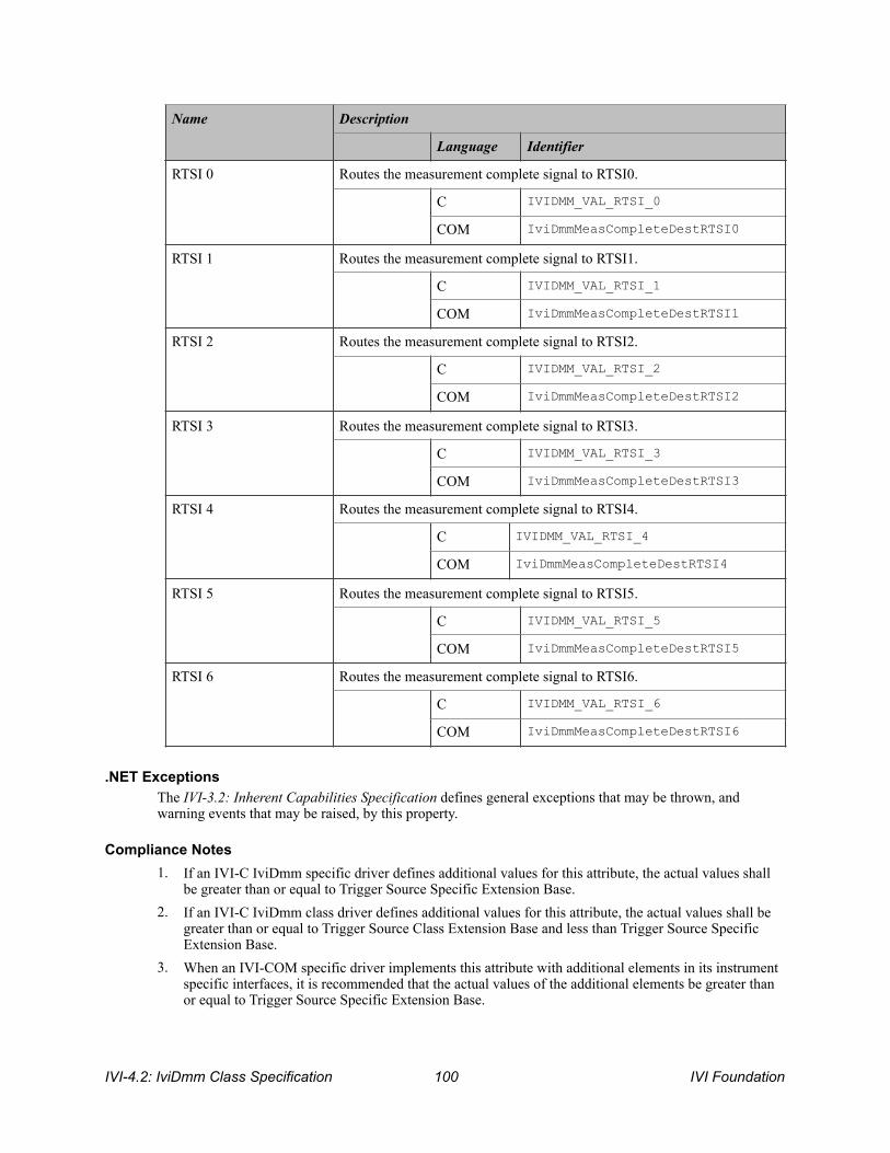
.NET Exceptions The IVI-3.2: Inherent Capabilities Specification defines general exceptions that may be thrown, and warning events that may be raised, by this property.
Compliance Notes 1. If an IVI-C IviDmm specific driver defines additional values for this attribute, the actual values shall
be greater than or equal to Trigger Source Specific Extension Base. 2. If an IVI-C IviDmm class driver defines additional values for this attribute, the actual values shall be
greater than or equal to Trigger Source Class Extension Base and less than Trigger Source Specific Extension Base.
3. When an IVI-COM specific driver implements this attribute with additional elements in its instrument specific interfaces, it is recommended that the actual values of the additional elements be greater than or equal to Trigger Source Specific Extension Base.
RTSI 0 Routes the measurement complete signal to RTSI0.
C IVIDMM_VAL_RTSI_0
COM IviDmmMeasCompleteDestRTSI0
RTSI 1 Routes the measurement complete signal to RTSI1.
C IVIDMM_VAL_RTSI_1
COM IviDmmMeasCompleteDestRTSI1
RTSI 2 Routes the measurement complete signal to RTSI2.
C IVIDMM_VAL_RTSI_2
COM IviDmmMeasCompleteDestRTSI2
RTSI 3 Routes the measurement complete signal to RTSI3.
C IVIDMM_VAL_RTSI_3
COM IviDmmMeasCompleteDestRTSI3
RTSI 4 Routes the measurement complete signal to RTSI4.
C IVIDMM_VAL_RTSI_4
COM IviDmmMeasCompleteDestRTSI4
RTSI 5 Routes the measurement complete signal to RTSI5.
C IVIDMM_VAL_RTSI_5
COM IviDmmMeasCompleteDestRTSI5
RTSI 6 Routes the measurement complete signal to RTSI6.
C IVIDMM_VAL_RTSI_6
COM IviDmmMeasCompleteDestRTSI6
Name Description
Language Identifier
IVI-4.2: IviDmm Class Specification ! IVI Foundation 100

See Section 19, Attribute Value Definitions, for the definitions of Trigger Source Specific Extension Base and Trigger Source Class Extension Base.
IVI Foundation ! IVI-4.2: IviDmm Class Specification 101

11.2.2.Sample Count
.NET Property Name Trigger.MultiPoint.SampleCount
COM Property Name Trigger.MultiPoint.SampleCount
C Constant Name IVIDMM_ATTR_SAMPLE_COUNT
Description Specifies the number of measurements the DMM takes each time it receives a trigger.
.NET Exceptions The IVI-3.2: Inherent Capabilities Specification defines general exceptions that may be thrown, and warning events that may be raised, by this property.
Data Type Access Applies To Coercion High Level Functions
ViInt32 R/W N/A None Configure Multi Point
IVI-4.2: IviDmm Class Specification ! IVI Foundation 102

11.2.3.Sample Interval
.NET Property Name Trigger.MultiPoint.SampleInterval
COM Property Name Trigger.MultiPoint.SampleInterval
C Constant Name IVIDMM_ATTR_SAMPLE_INTERVAL
Description Specifies the positive interval between samples. This attribute affects instrument behavior only when Sample Count is greater than 1 and Sample Trigger is Interval. For C and COM, the units are seconds. For .NET, the units are implicit in the definition of PrecisionTimeSpan.
.NET Exceptions The IVI-3.2: Inherent Capabilities Specification defines general exceptions that may be thrown, and warning events that may be raised, by this property.
Compliance Notes 1. IviDmm specific drivers that implement this attribute must implement the Interval value for the
Sample Trigger attribute.
Data Type Access Applies To Coercion High Level Functions
ViReal64 (C/COM) Ivi.Driver.PrecisionTimeSpan (.NET)
R/W N/A Up Configure Multi Point
IVI Foundation ! IVI-4.2: IviDmm Class Specification 103
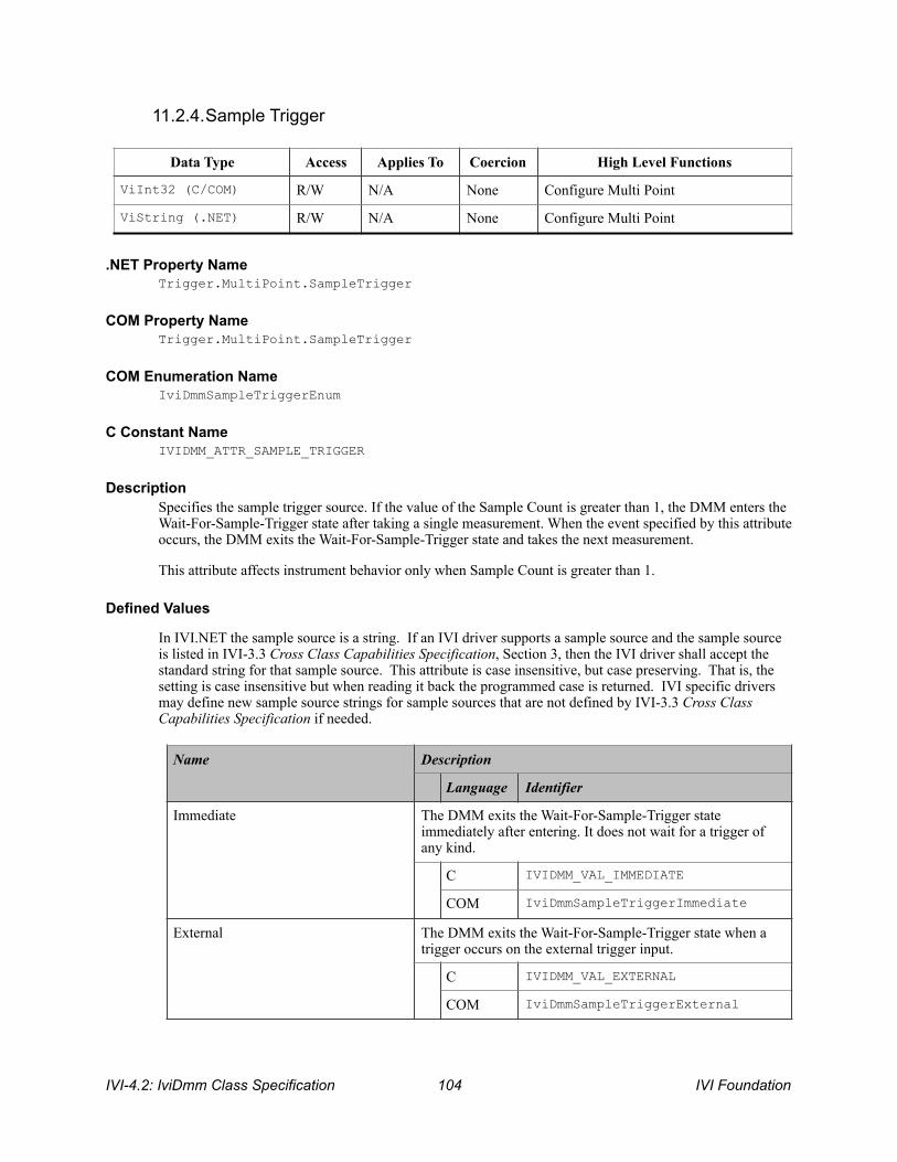
11.2.4.Sample Trigger
.NET Property Name Trigger.MultiPoint.SampleTrigger
COM Property Name Trigger.MultiPoint.SampleTrigger
COM Enumeration Name IviDmmSampleTriggerEnum
C Constant Name IVIDMM_ATTR_SAMPLE_TRIGGER
Description Specifies the sample trigger source. If the value of the Sample Count is greater than 1, the DMM enters the Wait-For-Sample-Trigger state after taking a single measurement. When the event specified by this attribute occurs, the DMM exits the Wait-For-Sample-Trigger state and takes the next measurement.
This attribute affects instrument behavior only when Sample Count is greater than 1.
Defined Values
In IVI.NET the sample source is a string. If an IVI driver supports a sample source and the sample source is listed in IVI-3.3 Cross Class Capabilities Specification, Section 3, then the IVI driver shall accept the standard string for that sample source. This attribute is case insensitive, but case preserving. That is, the setting is case insensitive but when reading it back the programmed case is returned. IVI specific drivers may define new sample source strings for sample sources that are not defined by IVI-3.3 Cross Class Capabilities Specification if needed.
Data Type Access Applies To Coercion High Level Functions
ViInt32 (C/COM) R/W N/A None Configure Multi Point
ViString (.NET) R/W N/A None Configure Multi Point
Name Description
Language Identifier
Immediate The DMM exits the Wait-For-Sample-Trigger state immediately after entering. It does not wait for a trigger of any kind.
C IVIDMM_VAL_IMMEDIATE
COM IviDmmSampleTriggerImmediate
External The DMM exits the Wait-For-Sample-Trigger state when a trigger occurs on the external trigger input.
C IVIDMM_VAL_EXTERNAL
COM IviDmmSampleTriggerExternal
IVI-4.2: IviDmm Class Specification ! IVI Foundation 104

Software Trigger The DMM exits the Wait-For-Sample-Trigger state when the Send Software Trigger function executes. Refer to the Standardized Cross Class Capabilities specification for a complete description of this value and the Send Software Trigger function.
C IVIDMM_VAL_SOFTWARE_TRIG
COM IviDmmSampleTriggerSwTrigFunc
Interval The DMM exits the Wait-For-Sample-Trigger state when the length of time specified by the Sample Interval attribute elapses.
C IVIDMM_VAL_INTERVAL
COM IviDmmSampleTriggerInterval
TTL0 The DMM exits the Wait-For-Sample-Trigger state when it receives a trigger on TTL0.
C IVIDMM_VAL_TTL0
COM IviDmmSampleTriggerTTL0
TTL1 The DMM exits the Wait-For-Sample-Trigger state when it receives a trigger on TTL1.
C IVIDMM_VAL_TTL1
COM IviDmmSampleTriggerTTL1
TTL2 The DMM exits the Wait-For-Sample-Trigger state when it receives a trigger on TTL2.
C IVIDMM_VAL_TTL2
COM IviDmmSampleTriggerTTL2
TTL3 The DMM exits the Wait-For-Sample-Trigger state when it receives a trigger on TTL3.
C IVIDMM_VAL_TTL3
COM IviDmmSampleTriggerTTL3
TTL4 The DMM exits the Wait-For-Sample-Trigger state when it receives a trigger on TTL4.
C IVIDMM_VAL_TTL4
COM IviDmmSampleTriggerTTL4
TTL5 The DMM exits the Wait-For-Sample-Trigger state when it receives a trigger on TTL5.
C IVIDMM_VAL_TTL5
COM IviDmmSampleTriggerTTL5
Name Description
Language Identifier
IVI Foundation ! IVI-4.2: IviDmm Class Specification 105

TTL6 The DMM exits the Wait-For-Sample-Trigger state when it receives a trigger on TTL6.
C IVIDMM_VAL_TTL6
COM IviDmmSampleTriggerTTL6
TTL7 The DMM exits the Wait-For-Sample-Trigger state when it receives a trigger on TTL7.
C IVIDMM_VAL_TTL7
COM IviDmmSampleTriggerTTL7
ECL0 The DMM exits the Wait-For-Sample-Trigger state when it receives a trigger on ECL0.
C IVIDMM_VAL_ECL0
COM IviDmmSampleTriggerECL0
ECL1 The DMM exits the Wait-For-Sample-Trigger state when it receives a trigger on ECL1.
C IVIDMM_VAL_ECL1
COM IviDmmSampleTriggerECL1
PXI Star The DMM exits the Wait-For-Sample-Trigger state when it receives a trigger on the PXI Star trigger bus.
C IVIDMM_VAL_PXI_STAR
COM IviDmmSampleTriggerPXIStar
RTSI 0 The DMM exits the Wait-For-Sample-Trigger state when it receives a trigger on RTSI0.
C IVIDMM_VAL_RTSI_0
COM IviDmmSampleTriggerRTSI0
RTSI 1 The DMM exits the Wait-For-Sample-Trigger state when it receives a trigger on RTSI1.
C IVIDMM_VAL_RTSI_1
COM IviDmmSampleTriggerRTSI1
RTSI 2 The DMM exits the Wait-For-Sample-Trigger state when it receives a trigger on RTSI2.
C IVIDMM_VAL_RTSI_2
COM IviDmmSampleTriggerRTSI2
RTSI 3 The DMM exits the Wait-For-Sample-Trigger state when it receives a trigger on RTSI3.
C IVIDMM_VAL_RTSI_3
Name Description
Language Identifier
IVI-4.2: IviDmm Class Specification ! IVI Foundation 106

.NET Exceptions The IVI-3.2: Inherent Capabilities Specification defines general exceptions that may be thrown, and warning events that may be raised, by this property.
Compliance Notes 1. If an IviDmm specific driver implements any of the defined values in the following table, it must also
implement the corresponding capability group:
2. If the IviDmm specific driver implements the Interval defined value, then it must also implement the Sample Interval attribute.
3. If an IVI-C IviDmm specific driver defines additional values for this attribute, the actual values must be greater than or equal to Trigger Source Specific Extension Base.
4. If an IVI-C IviDmm class driver defines additional values for this attribute, the actual values must be greater than or equal to Trigger Source Class Extension Base and less than Trigger Source Specific Extension Base.
5. When an IVI-COM specific driver implements this attribute with additional elements in its instrument specific interfaces, it is recommended that the actual values of the additional elements be greater than or equal to Trigger Source Specific Extension Base.
See Section 19, Attribute Value Definitions, for the definitions of Trigger Source Specific Extension Base and Trigger Source Class Extension Base.
COM IviDmmSampleTriggerRTSI3
RTSI 4 The DMM exits the Wait-For-Sample-Trigger state when it receives a trigger on RTSI4.
C IVIDMM_VAL_RTSI_4
COM IviDmmSampleTriggerRTSI4
RTSI 5 The DMM exits the Wait-For-Sample-Trigger state when it receives a trigger on RTSI5.
C IVIDMM_VAL_RTSI_5
COM IviDmmSampleTriggerRTSI5
RTSI 6 The DMM exits the Wait-For-Sample-Trigger state when it receives a trigger on RTSI6.
C IVIDMM_VAL_RTSI_6
COM IviDmmSampleTriggerRTSI6
Name Description
Language Identifier
Value Required Capability Group
Software Trigger IviDmmSoftwareTrigger
IVI Foundation ! IVI-4.2: IviDmm Class Specification 107

11.2.5.Trigger Count
.NET Property Name Trigger.MultiPoint.Count
COM Property Name Trigger.MultiPoint.Count
C Constant Name IVIDMM_ATTR_TRIGGER_COUNT
Description Specifies the number of triggers the DMM accepts before it returns to the idle state.
.NET Exceptions The IVI-3.2: Inherent Capabilities Specification defines general exceptions that may be thrown, and warning events that may be raised, by this property.
Data Type Access Applies To Coercion High Level Functions
ViInt32 R/W N/A None Configure Multi Point
IVI-4.2: IviDmm Class Specification ! IVI Foundation 108

11.3.IviDmmMultiPoint Functions The IviDmmMultiPoint extension group defines the following functions: • Configure Measure Complete Destination (IVI-C only) • Configure Multi Point • Fetch Multi Point • Read Multi Point
This section describes the behavior and requirements of each function.
IVI Foundation ! IVI-4.2: IviDmm Class Specification 109
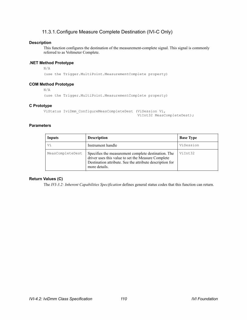
11.3.1.Configure Measure Complete Destination (IVI-C Only)
Description This function configures the destination of the measurement-complete signal. This signal is commonly referred to as Voltmeter Complete.
.NET Method Prototype N/A
(use the Trigger.MultiPoint.MeasurementComplete property)
COM Method Prototype N/A
(use the Trigger.MultiPoint.MeasurementComplete property)
C Prototype ViStatus IviDmm_ConfigureMeasCompleteDest (ViSession Vi, ViInt32 MeasCompleteDest);
Parameters
Return Values (C) The IVI-3.2: Inherent Capabilities Specification defines general status codes that this function can return.
Inputs Description Base Type
Vi Instrument handle ViSession
MeasCompleteDest Specifies the measurement complete destination. The driver uses this value to set the Measure Complete Destination attribute. See the attribute description for more details.
ViInt32
IVI-4.2: IviDmm Class Specification ! IVI Foundation 110
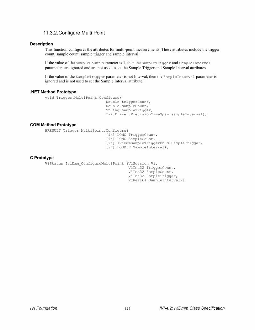
11.3.2.Configure Multi Point
Description This function configures the attributes for multi-point measurements. These attributes include the trigger count, sample count, sample trigger and sample interval.
If the value of the SampleCount parameter is 1, then the SampleTrigger and SampleInterval parameters are ignored and are not used to set the Sample Trigger and Sample Interval attributes.
If the value of the SampleTrigger parameter is not Interval, then the SampleInterval parameter is ignored and is not used to set the Sample Interval attribute.
.NET Method Prototype void Trigger.MultiPoint.Configure( Double triggerCount, Double sampleCount, String sampleTrigger, Ivi.Driver.PrecisionTimeSpan sampleInterval);
COM Method Prototype HRESULT Trigger.MultiPoint.Configure( [in] LONG TriggerCount, [in] LONG SampleCount, [in] IviDmmSampleTriggerEnum SampleTrigger, [in] DOUBLE SampleInterval);
C Prototype ViStatus IviDmm_ConfigureMultiPoint (ViSession Vi, ViInt32 TriggerCount, ViInt32 SampleCount, ViInt32 SampleTrigger, ViReal64 SampleInterval);
IVI Foundation ! IVI-4.2: IviDmm Class Specification 111

Parameters
Return Values (C/COM) The IVI-3.2: Inherent Capabilities Specification defines general status codes that this function can return.
.NET Exceptions The IVI-3.2: Inherent Capabilities Specification defines general exceptions that may be thrown, and warning events that may be raised, by this method.
Inputs Description Base Type
Vi Instrument handle ViSession
TriggerCount Specifies the trigger count. The driver uses this value to set the Trigger Count attribute. See the attribute description for more details.
ViInt32
SampleCount Specifies the sample count. The driver uses this value to set the Sample Count attribute. See the attribute description for more details
ViInt32
SampleTrigger Specifies the sample trigger source. The driver uses this value to set the Sample Trigger attribute. See the attribute description for more details
ViInt32 (C/COM) ViString (.NET)
SampleInterval Specifies the sample interval. The driver uses this value to set the Sample Interval attribute. See the attribute description for more details
ViReal64 (C/COM) Ivi.Driver. PrecisionTimeSpan (.NET)
IVI-4.2: IviDmm Class Specification ! IVI Foundation 112
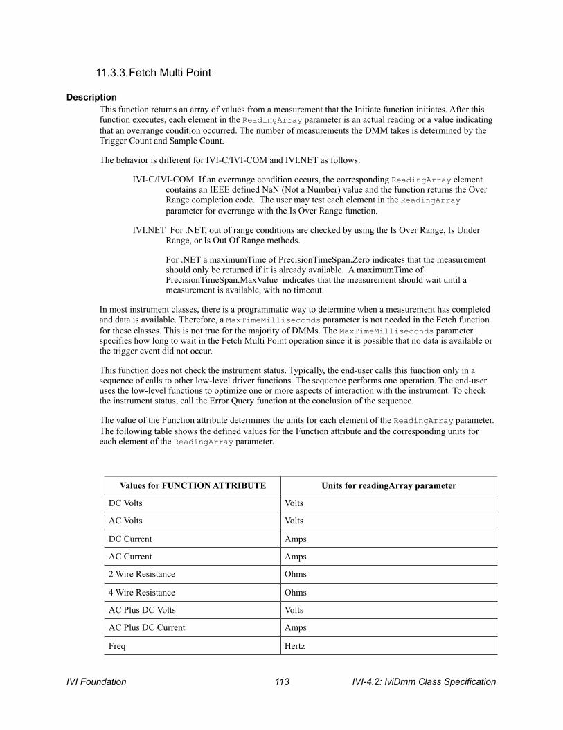
11.3.3.Fetch Multi Point
Description This function returns an array of values from a measurement that the Initiate function initiates. After this function executes, each element in the ReadingArray parameter is an actual reading or a value indicating that an overrange condition occurred. The number of measurements the DMM takes is determined by the Trigger Count and Sample Count.
The behavior is different for IVI-C/IVI-COM and IVI.NET as follows:
IVI-C/IVI-COM If an overrange condition occurs, the corresponding ReadingArray element contains an IEEE defined NaN (Not a Number) value and the function returns the Over Range completion code. The user may test each element in the ReadingArray parameter for overrange with the Is Over Range function.
IVI.NET For .NET, out of range conditions are checked by using the Is Over Range, Is Under Range, or Is Out Of Range methods.
For .NET a maximumTime of PrecisionTimeSpan.Zero indicates that the measurement should only be returned if it is already available. A maximumTime of PrecisionTimeSpan.MaxValue indicates that the measurement should wait until a measurement is available, with no timeout.
In most instrument classes, there is a programmatic way to determine when a measurement has completed and data is available. Therefore, a MaxTimeMilliseconds parameter is not needed in the Fetch function for these classes. This is not true for the majority of DMMs. The MaxTimeMilliseconds parameter specifies how long to wait in the Fetch Multi Point operation since it is possible that no data is available or the trigger event did not occur.
This function does not check the instrument status. Typically, the end-user calls this function only in a sequence of calls to other low-level driver functions. The sequence performs one operation. The end-user uses the low-level functions to optimize one or more aspects of interaction with the instrument. To check the instrument status, call the Error Query function at the conclusion of the sequence.
The value of the Function attribute determines the units for each element of the ReadingArray parameter. The following table shows the defined values for the Function attribute and the corresponding units for each element of the ReadingArray parameter.
Values for FUNCTION ATTRIBUTE Units for readingArray parameter
DC Volts Volts
AC Volts Volts
DC Current Amps
AC Current Amps
2 Wire Resistance Ohms
4 Wire Resistance Ohms
AC Plus DC Volts Volts
AC Plus DC Current Amps
Freq Hertz
IVI Foundation ! IVI-4.2: IviDmm Class Specification 113
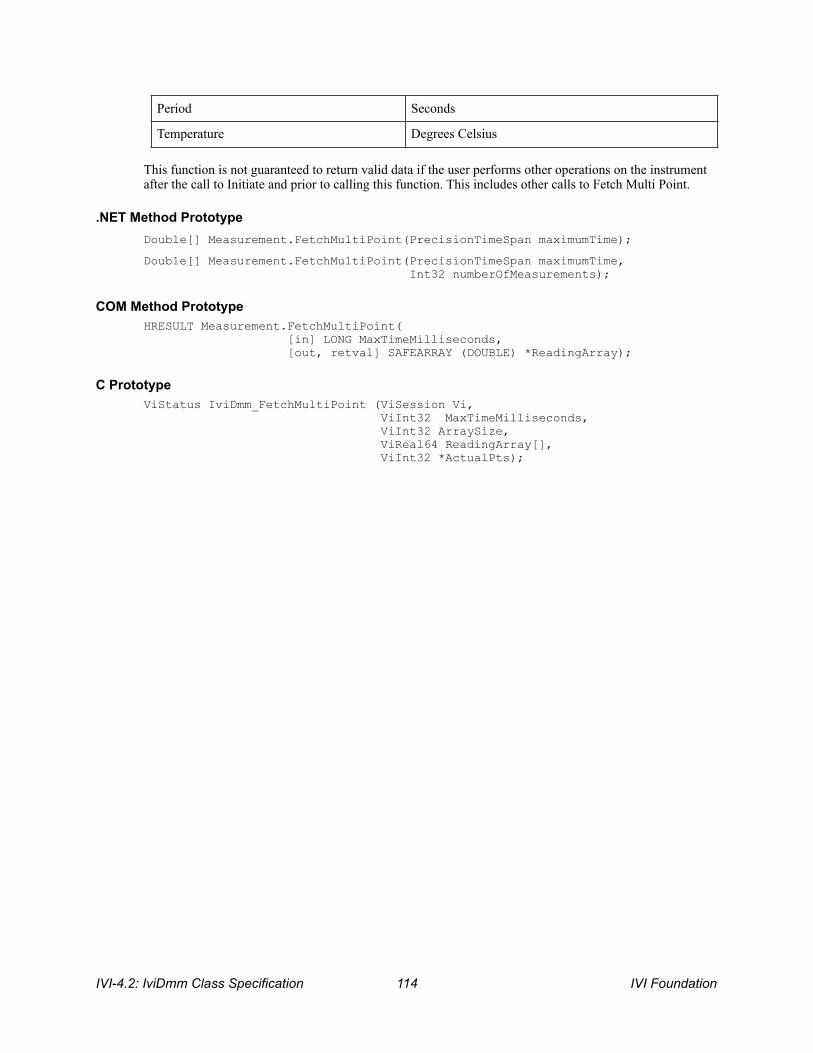
This function is not guaranteed to return valid data if the user performs other operations on the instrument after the call to Initiate and prior to calling this function. This includes other calls to Fetch Multi Point.
.NET Method Prototype Double[] Measurement.FetchMultiPoint(PrecisionTimeSpan maximumTime);
Double[] Measurement.FetchMultiPoint(PrecisionTimeSpan maximumTime, Int32 numberOfMeasurements);
COM Method Prototype HRESULT Measurement.FetchMultiPoint( [in] LONG MaxTimeMilliseconds, [out, retval] SAFEARRAY (DOUBLE) *ReadingArray);
C Prototype ViStatus IviDmm_FetchMultiPoint (ViSession Vi, ViInt32 MaxTimeMilliseconds, ViInt32 ArraySize, ViReal64 ReadingArray[], ViInt32 *ActualPts);
Period Seconds
Temperature Degrees Celsius
IVI-4.2: IviDmm Class Specification ! IVI Foundation 114

Parameters
Defined Values for the MaxTimeMilliseconds Parameter
Defined Values for the MaximumTime Parameter (.NET)
Inputs Description Base Type
Vi Instrument handle ViSession
MaxTimeMilliseconds (C/COM)
Specifies the maximum length of time allowed for the function to complete in milliseconds.
ViInt32
maximumTime (.NET) Specifies the maximum length of time allowed for the function to complete.
PrecisionTimeSpan
ArraySize Specifies the number of elements in the readingArray.
ViInt32
numberOfMeasurements (.NET)
The number of measurements to be returned from the multi-point measurement. If this number is greater than (Trigger Count * Sample Count), the method will return exactly (Trigger Count * Sample Count) measurements.
ViInt32
Outputs Description Base Type
ReadingArray (C/COM)
A user-allocated (for IVI_C) or driver-allocated (for IVI-COM) buffer into which the measured values are stored.
ViReal64[]
ActualPts The number of measured values placed in readingArray.
ViInt32
Return value (.NET) A driver-allocated buffer into which the measured values are stored.
ViReal64[]
Name Description
Language Identifier
Max Time Immediate
The function returns immediately. If no valid measurement value exists, the function returns an error.
C IVIDMM_VAL_MAX_TIME_IMMEDIATE
COM IviDmmMaxTimeImmediate
Max Time Infinite The function waits indefinitely for the measurement to complete.
C IVIDMM_VAL_MAX_TIME_INFINITE
COM IviDmmMaxTimeInfinite
IVI Foundation ! IVI-4.2: IviDmm Class Specification 115

Return Values (C/COM) The IVI-3.2: Inherent Capabilities Specification defines general status codes that this function can return. The table below specifies additional class-defined status codes for this function.
.NET Exceptions The IVI-3.2: Inherent Capabilities Specification defines general exceptions that may be thrown, and warning events that may be raised, by this method.
Note that the .NET MaxTimeExceededException is defined in IVI-3.2: Inherent Capabilities Specification.
Name Description
Language Identifier
Zero The function returns immediately. If no valid measurement value exists, the function returns an error.
.NET PrecisionTimeSpan.Zero
MaxValue The function waits indefinitely for the measurement to complete.
.NET PrecisionTimeSpan.MaxValue
Completion Codes Description
Over Range Overrange warning
Max Time Exceeded Max time exceeded before the operation completed
IVI-4.2: IviDmm Class Specification ! IVI Foundation 116

11.3.4.Read Multi Point
Description This function initiates the measurement, waits for the DMM to return to the Idle state, and returns an array of measured values. The number of measurements the DMM takes is determined by the Trigger Count and Sample Count.
The behavior is different for IVI-C/IVI-Com and IVI.NET as follows:
IVI-C/IVI-COM, After this function executes, each element in the ReadingArray parameter is an actual reading or a value indicating that an overrange condition occurred. If an overrange condition occurs, the corresponding ReadingArray element contains an IEEE defined NaN (Not a Number) value and the function returns Over Range. Test each element in the ReadingArray parameter for overrange with the Is Over Range function.
IVI.NET For .NET, out of range conditions are checked by using the Is Over Range, Is Under Range, or Is Out Of Range methods.
The value of the Function attribute determines the units for each element of the ReadingArray parameter. Refer to Section 11.3.3, Fetch Multi Point for more details.
.NET Method Prototype Double[] Measurement.ReadMultiPoint(PrecisionTimeSpan maximumTime);
Double[] Measurement.ReadMultiPoint(PrecisionTimeSpan maximumTime, Int32 numberOfMeasurements);
COM Method Prototype HRESULT Measurement.ReadMultiPoint( [in] LONG MaxTimeMilliseconds, [out, retval] SAFEARRAY (DOUBLE) *ReadingArray);
C Prototype ViStatus IviDmm_ReadMultiPoint (ViSession Vi, ViInt32 MaxTimeMilliseconds, ViInt32 ArraySize, ViReal64 ReadingArray[], ViInt32 *ActualPts);
IVI Foundation ! IVI-4.2: IviDmm Class Specification 117

Parameters
Defined Values for the MaxTimeMilliseconds Parameter
Defined Values for the MaximumTime Parameter (.NET)
Inputs Description Base Type
Vi Instrument handle ViSession
MaxTimeMilliseconds (C/COM)
Specifies the maximum length of time allowed for the function to complete in milliseconds.
ViInt32
maximumTime (.NET) Specifies the maximum length of time allowed for the function to complete.
PrecisionTimeSpan
ArraySize Specifies the number of elements in the readingArray.
ViInt32
numberOfMeasurements (.NET)
The number of measurements to be returned from the multi-point measurement. If this number is greater than (Trigger Count * Sample Count), the method will return exactly (Trigger Count * Sample Count) measurements.
ViInt32
Outputs Description Base Type
ReadingArray (C/COM)
A user-allocated (for IVI_C) or driver-allocated (for IVI-COM) buffer into which the measured values are stored.
ViReal64[]
ActualPts The number of measured values placed in readingArray.
ViInt32
Return value (.NET) A driver-allocated buffer into which the measured values are stored.
ViReal64[]
Name Description
Language Identifier
Max Time Immediate
The function returns immediately. If no valid measurement value exists, the function returns an error.
C IVIDMM_VAL_MAX_TIME_IMMEDIATE
COM IviDmmMaxTimeImmediate
Max Time Infinite The function waits indefinitely for the measurement to complete.
C IVIDMM_VAL_MAX_TIME_INFINITE
COM IviDmmMaxTimeInfinite
IVI-4.2: IviDmm Class Specification ! IVI Foundation 118

Return Values (C/COM) The IVI-3.2: Inherent Capabilities Specification defines general status codes that this function can return. The table below specifies additional class-defined status codes for this function.
.NET Exceptions
The IVI-3.2: Inherent Capabilities Specification defines general exceptions that may be thrown, and warning events that may be raised, by this method.
Note that the .NET MaxTimeExceededException is defined in IVI-3.2: Inherent Capabilities Specification.
Name Description
Language Identifier
Zero The function returns immediately. If no valid measurement value exists, the function returns an error.
.NET PrecisionTimeSpan.Zero
MaxValue The function waits indefinitely for the measurement to complete.
.NET PrecisionTimeSpan.MaxValue
Completion Codes Description
Over Range Overrange warning
Max Time Exceeded Max time exceeded before the operation completed
IVI Foundation ! IVI-4.2: IviDmm Class Specification 119
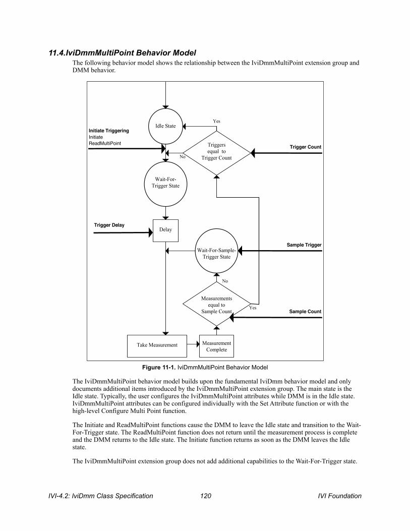
11.4.IviDmmMultiPoint Behavior Model The following behavior model shows the relationship between the IviDmmMultiPoint extension group and DMM behavior.
! Figure 11-1. IviDmmMultiPoint Behavior Model
The IviDmmMultiPoint behavior model builds upon the fundamental IviDmm behavior model and only documents additional items introduced by the IviDmmMultiPoint extension group. The main state is the Idle state. Typically, the user configures the IviDmmMultiPoint attributes while DMM is in the Idle state. IviDmmMultiPoint attributes can be configured individually with the Set Attribute function or with the high-level Configure Multi Point function.
The Initiate and ReadMultiPoint functions cause the DMM to leave the Idle state and transition to the Wait-For-Trigger state. The ReadMultiPoint function does not return until the measurement process is complete and the DMM returns to the Idle state. The Initiate function returns as soon as the DMM leaves the Idle state.
The IviDmmMultiPoint extension group does not add additional capabilities to the Wait-For-Trigger state.
Wait-For- Trigger State
Wait-For-Sample- Trigger State
Initiate Triggering Initiate ReadMultiPoint
Sample Trigger
Trigger Count
Sample Count
Trigger Delay
Yes
Yes
No
Idle State
Delay
Take Measurement
No
Measurement Complete
Measurements equal to
Sample Count
Triggers equal to
Trigger Count
IVI-4.2: IviDmm Class Specification ! IVI Foundation 120
After the DMM leaves the Wait-For-Trigger state, it then executes a delay. The length of the delay is specified by the attribute Trigger Delay. After the measurement is taken, the DMM then, if it is capable of doing so, generates the Measurement Complete signal.
The DMM then compares the sample count with the number of measurements taken since the last trigger event. The sample count is specified by the attribute Sample Count. If the number measurements is not equal to the sample count the DMM moves to the Wait-For-Sample-Trigger state. The DMM remains in the Wait-For-Sample-Trigger state until the event specified by the attribute Sample Trigger occurs. Then it takes another measurement.
Once the number of measurements taken is equal to the sample count, the DMM then compares the number trigger count with the number of trigger events that have occurred since either the Initiate or Read Multi Point function was called. The trigger count is specified by the attribute Trigger Count. If the number of trigger events is not equal to the trigger count, the DMM returns to the Wait-For-Trigger state.
Once the number of trigger events is equal to the trigger count, the DMM returns to the Idle state. The Fetch Multi Point function is used to retrieve measured data from measurements initiated by the Initiate function. The measurement data returned from the Read Multi Point and Fetch Multi Point functions is acquired after the DMM has left the Wait-For-Trigger state.
IVI Foundation ! IVI-4.2: IviDmm Class Specification 121
12.IviDmmTriggerSlope Extension Group
12.1.IviDmmTriggerSlope Extension Group Overview The IviDmmTriggerSlope extension group supports DMMs that can specify the polarity of the external trigger signal. It defines an attribute and a function to configure this polarity.
Special Note To Users Typically the specific driver disables extension groups that the application program does not explicitly use or enable. The IviDmmTriggerSlope extension capability group affects the behavior of the instrument regardless of the value of the Trigger Slope attribute. It is not possible for the specific driver to disable this extension capability group.
Therefore, it is the responsibility of the user to ensure that the slope of the trigger signal is correct for their application. Most DMMs do not have a programmable trigger slope and do not implement the IviDmmTriggerSlope extension capability group. Users should avoid using the IviDmmTriggerSlope extension capability in their test program source code so that they can maximize the set of instruments that they can use interchangeably.
For instrument drivers that implement the IviDmmTriggerSlope extension, the user can set the value of the Trigger Slope attribute in the IVI configuration file. For instruments that do not implement the IviDmmTriggerSlope extension group, the user must ensure that trigger signal that their instrument receives has the correct polarity. This can be done with external circuitry.
12.2.IviDmmTriggerSlope Attributes The IviDmmTriggerSlope extension group defines the following attribute: • Trigger Slope
This section describes the behavior and requirements of this attribute. The actual value for each attribute ID is defined in Section 18, IviDmm Attribute ID Definitions.
IVI-4.2: IviDmm Class Specification ! IVI Foundation 122
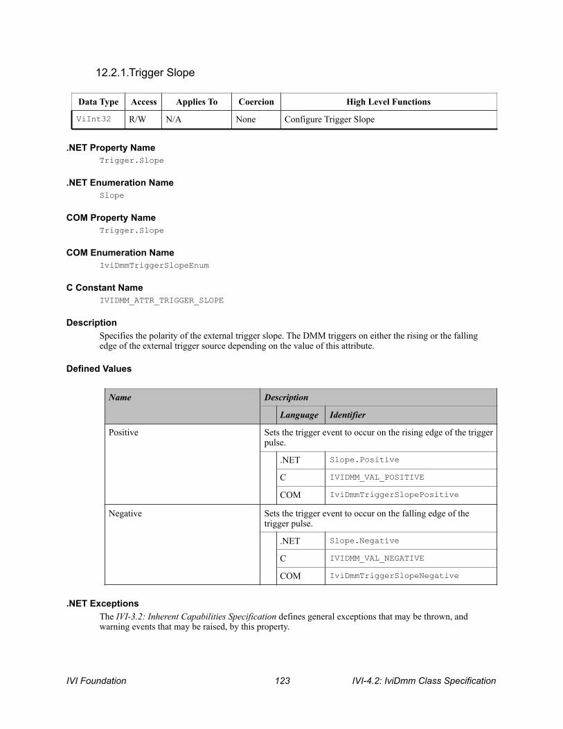
12.2.1.Trigger Slope
.NET Property Name Trigger.Slope
.NET Enumeration Name Slope
COM Property Name Trigger.Slope
COM Enumeration Name IviDmmTriggerSlopeEnum
C Constant Name IVIDMM_ATTR_TRIGGER_SLOPE
Description Specifies the polarity of the external trigger slope. The DMM triggers on either the rising or the falling edge of the external trigger source depending on the value of this attribute.
Defined Values
.NET Exceptions The IVI-3.2: Inherent Capabilities Specification defines general exceptions that may be thrown, and warning events that may be raised, by this property.
Data Type Access Applies To Coercion High Level Functions
ViInt32 R/W N/A None Configure Trigger Slope
Name Description
Language Identifier
Positive Sets the trigger event to occur on the rising edge of the trigger pulse.
.NET Slope.Positive
C IVIDMM_VAL_POSITIVE
COM IviDmmTriggerSlopePositive
Negative Sets the trigger event to occur on the falling edge of the trigger pulse.
.NET Slope.Negative
C IVIDMM_VAL_NEGATIVE
COM IviDmmTriggerSlopeNegative
IVI Foundation ! IVI-4.2: IviDmm Class Specification 123
Compliance Notes 1. If an IVI-C IviDmm specific driver defines additional values for this attribute, the magnitude of the
actual values must be greater than or equal to Trigger Slope Specific Extension Base.
2. If an IVI-C IviDmm class driver defines additional values for this attribute, the magnitude of the actual values must be greater than or equal to Trigger Slope Class Extension Base and less than Trigger Slope Specific Extension Base.
3. When an IVI-COM specific driver implements this attribute with additional elements in its instrument specific interfaces, it is recommended that the actual values of the additional elements be greater than or equal to Trigger Slope Specific Extension Base.
See Section 19, Attribute Value Definitions, for the definitions of Trigger Slope Specific Extension Base and Trigger Slope Class Extension Base.
IVI-4.2: IviDmm Class Specification ! IVI Foundation 124

12.3.IviDmmTriggerSlope Functions The IviDmmTriggerSlope extension group defines the following function: • Configure Trigger Slope (IVI-C only)
This section describes the behavior and requirements of this function.
IVI Foundation ! IVI-4.2: IviDmm Class Specification 125

12.3.1.Configure Trigger Slope (IVI-C Only)
Description This function configures the polarity of the external trigger source of the DMM.
.NET Method Prototype N/A
(use the Trigger.Slope property)
COM Method Prototype N/A
(use the Trigger.Slope property)
C Prototype ViStatus IviDmm_ConfigureTriggerSlope (ViSession Vi, ViInt32 Polarity);
Parameters
Return Values (C) The IVI-3.2: Inherent Capabilities Specification defines general status codes that this function can return.
Inputs Description Base Type
Vi Instrument handle ViSession
Polarity Specifies the trigger slope. The driver uses this value to set the Trigger Slope attribute. See the attribute description for more details.
ViInt32
IVI-4.2: IviDmm Class Specification ! IVI Foundation 126

12.4.IviDmmTriggerSlope Behavior Model The IviDmmTriggerSlope extension group follows the same behavior model as the IviDmmBase capability group described in Section 4.4, IviDmmBase Behavior Model.
IVI Foundation ! IVI-4.2: IviDmm Class Specification 127

13.IviDmmSoftwareTrigger Extension Group
13.1.IviDmmSoftwareTrigger Extension Group Overview The IviDmmSoftwareTrigger extension group supports DMMs that can initiate a measurement based on a software trigger signal. The user can send a software trigger to cause the DMM to initiate a measurement.
13.2.IviDmmSoftwareTrigger Functions The IviDmmSoftwareTrigger extension group defines the following function: • Send Software Trigger
This section describes the behavior and requirements of this function.
13.2.1.IviDmm_SendSoftwareTrigger Refer to IVI-3.3: Standardized Cross Class Capabilities Specification for the prototype and complete description of this function.
13.3.IviDmmSoftwareTrigger Behavior Model The behavior model of the IviDmmSoftwareTrigger follows the behavior model of the IviDmmBase capability group as described in Section 4.4, IviDmmBase Behavior Model and the IviDmmMultiPoint extension group described in Section 11.4, IviDmmMultiPoint Behavior Model. Furthermore, it defines an additional trigger event for the trigger source.
The DMM leaves the Wait-For-Trigger state when it receives a trigger event specified by the Trigger Source attribute. The DMM leaves the Wait-For-Sample-Trigger state when it receieves a trigger event specified by the Sample Trigger attribute When the trigger source or sample trigger is set to Software Trigger, the Send Software Trigger function is used to generate the trigger event . Calling this function causes the DMM to take a measurement.
13.4.IviDmmSoftwareTrigger Compliance Notes 1. IviDmm specific drivers that implement this extension group shall implement the Software Trigger
value for the Trigger Source attribute in the IviDmmBase capability group.
IVI-4.2: IviDmm Class Specification ! IVI Foundation 128
14.IviDmmDeviceInfo Extension Group
14.1.IviDmmDeviceInfo Extension Group Overview The IviDmmDeviceInfo extension group defines a set of read-only attributes for DMMs that can be queried to determine how they are presently configured. These attributes are the aperture time and the aperture time units.
14.2.IviDmmDeviceInfo Attributes The IviDmmDeviceInfo extension group defines the following attributes: • Aperture Time
• Aperture Time Units
This section describes the behavior and requirements of each attribute. The actual value for each attribute ID is defined in Section 18, IviDmm Attribute ID Definitions.
IVI Foundation ! IVI-4.2: IviDmm Class Specification 129

14.2.1.Aperture Time
.NET Property Name Advanced.ApertureTime
COM Property Name Advanced.ApertureTime
C Constant Name IVIDMM_ATTR_APERTURE_TIME
Description Returns the measurement aperture time based on the present configuration. The units for this attribute are specified by attribute Aperture Time Units.
The aperture time is also known as the integration time.
.NET Exceptions The IVI-3.2: Inherent Capabilities Specification defines general exceptions that may be thrown, and warning events that may be raised, by this property.
Data Type Access Applies To Coercion High Level Functions
ViReal64 RO N/A None Get Aperture Time Info
IVI-4.2: IviDmm Class Specification ! IVI Foundation 130

14.2.2.Aperture Time Units
.NET Property Name Advanced.ApertureTimeUnits
.NET Enumeration Name ApertureTimeUnits
COM Property Name Advanced.ApertureTimeUnits
COM Enumeration Name IviDmmApertureTimeUnitsEnum
C Constant Name IVIDMM_ATTR_APERTURE_TIME_UNITS
Description Returns the units for the Aperture Time attribute.
Defined Values
.NET Exceptions The IVI-3.2: Inherent Capabilities Specification defines general exceptions that may be thrown, and warning events that may be raised, by this property.
Data Type Access Applies To Coercion High Level Functions
ViInt32 RO N/A None Get Aperture Time Info
Name Description
Language Identifier
Seconds Reports that the units for the value returned by Aperture Time are seconds.
.NET ApertureTimeUnits.Seconds
C IVIDMM_VAL_SECONDS
COM IviDmmApertureSeconds
Power Line Cycles Reports that the units for the value returned by Aperture Time are Power Line Cycles.
.NET ApertureTimeUnits.PowerlineCycles
C IVIDMM_VAL_POWER_LINE_CYCLES
COM IviDmmAperturePowerLineCycles
IVI Foundation ! IVI-4.2: IviDmm Class Specification 131

14.3.IviDmmDeviceInfo Functions The IviDmmDeviceInfo extension group defines the following function: • Get Aperture Time Info (IVI-C only)
This section describes the behavior and requirements of this function.
IVI-4.2: IviDmm Class Specification ! IVI Foundation 132

14.3.1.Get Aperture Time Info (IVI-C Only)
Description This function returns additional information about the state of the instrument. Specifically, it returns the aperture time and the aperture time units.
.NET Method Prototype N/A
(use the Advanced.ApertureTime and Advanced.ApertureTimeUnits properties)
COM Method Prototype N/A
(use the Advanced.ApertureTime and Advanced.ApertureTimeUnits properties)
C Prototype ViStatus IviDmm_GetApertureTimeInfo (ViSession Vi ViReal64 *ApertureTime, ViInt32 *ApertureTimeUnits);
Parameters
Return Values (C) The IVI-3.2: Inherent Capabilities Specification defines general status codes that this function can return.
Inputs Description Base Type
Vi Instrument handle ViSession
Outputs Description Base Type
ApertureTime Returns the value of the Aperture Time attribute. See the attribute description for more details.
ViReal64
ApertureTimeUnits Returns the value of the Aperture Time Units attribute. See the attribute description for more details.
ViInt32
IVI Foundation ! IVI-4.2: IviDmm Class Specification 133

14.4.IviDmmDeviceInfo Behavior Model The IviDmmDeviceInfo extension group follows the same behavior model as the IviDmmBase capability group described in Section 4.4, IviDmmBase Behavior Model.
IVI-4.2: IviDmm Class Specification ! IVI Foundation 134

15.IviDmmAutoRangeValue Extension Group
15.1.IviDmmAutoRangeValue Extension Group Overview The IviDmmAutoRangeValue extension supports DMMs with the capability to return the actual range value when auto ranging.
15.2.IviDmmAutoRangeValue Attributes The IviDmmAutoRangeValue extension group defines the following attribute: • Auto Range Value
This section describes the behavior and requirements of this attribute. The actual value for each attribute ID is defined in Section 18, IviDmm Attribute ID Definitions.
IVI Foundation ! IVI-4.2: IviDmm Class Specification 135
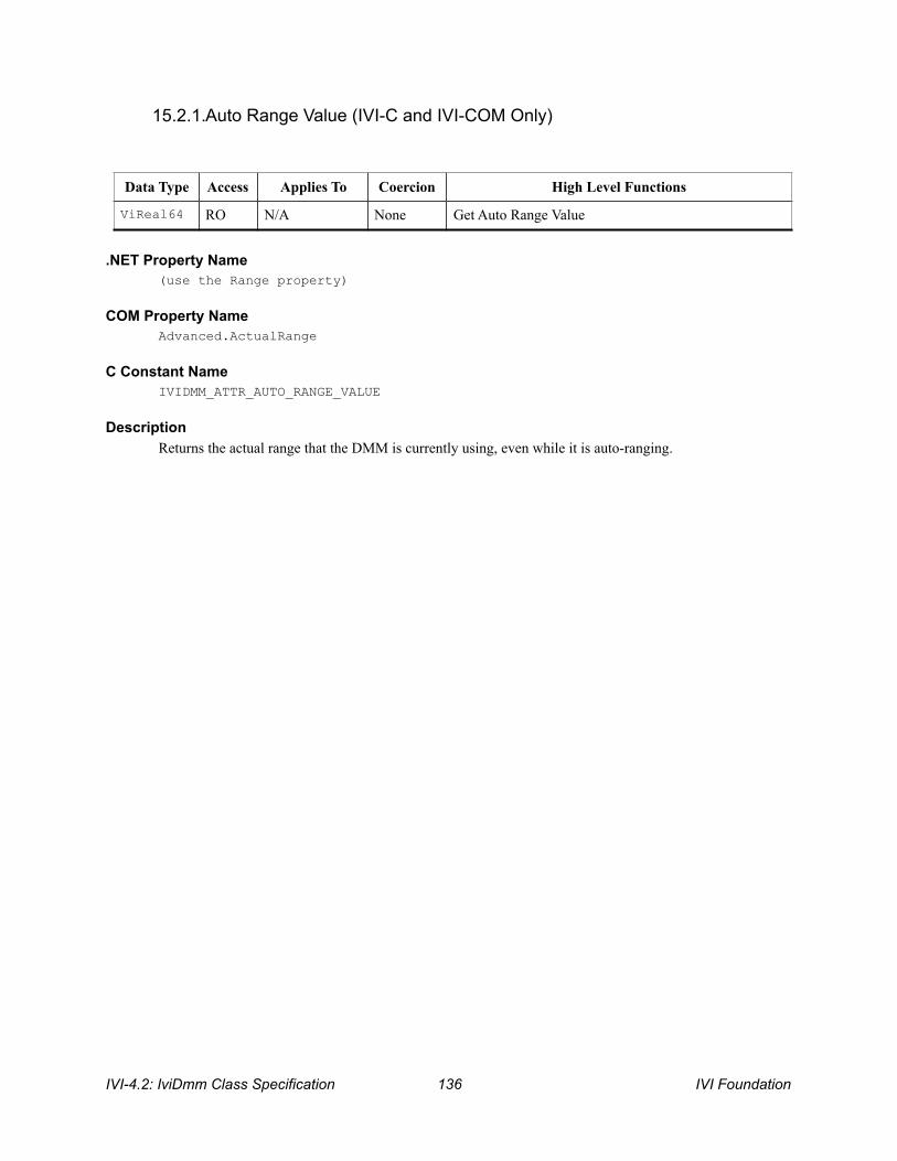
15.2.1.Auto Range Value (IVI-C and IVI-COM Only)
.NET Property Name (use the Range property)
COM Property Name Advanced.ActualRange
C Constant Name IVIDMM_ATTR_AUTO_RANGE_VALUE
Description Returns the actual range that the DMM is currently using, even while it is auto-ranging.
Data Type Access Applies To Coercion High Level Functions
ViReal64 RO N/A None Get Auto Range Value
IVI-4.2: IviDmm Class Specification ! IVI Foundation 136

15.3.IviDmmAutoRangeValue Functions The IviDmmAutoRangeValue extension group defines the following function: • Get Auto Range Value (IVI-C only)
This section describes the behavior and requirements of this function.
IVI Foundation ! IVI-4.2: IviDmm Class Specification 137
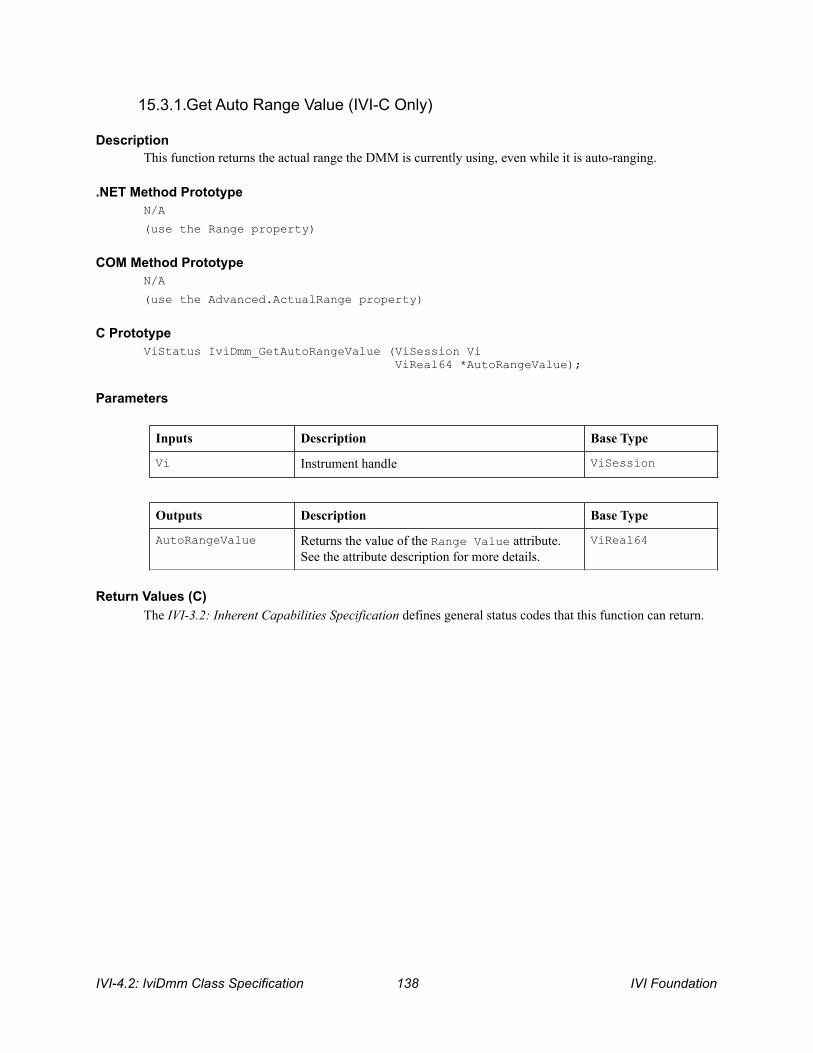
15.3.1.Get Auto Range Value (IVI-C Only)
Description This function returns the actual range the DMM is currently using, even while it is auto-ranging.
.NET Method Prototype N/A
(use the Range property)
COM Method Prototype N/A
(use the Advanced.ActualRange property)
C Prototype ViStatus IviDmm_GetAutoRangeValue (ViSession Vi ViReal64 *AutoRangeValue);
Parameters
Return Values (C) The IVI-3.2: Inherent Capabilities Specification defines general status codes that this function can return.
Inputs Description Base Type
Vi Instrument handle ViSession
Outputs Description Base Type
AutoRangeValue Returns the value of the Range Value attribute. See the attribute description for more details.
ViReal64
IVI-4.2: IviDmm Class Specification ! IVI Foundation 138

15.4.IviDmmAutoRangeValue Behavior Model The IviDmmAutoRangeValue extension group follows the same behavior model as the IviDmmBase capability group described in Section 4.4, IviDmmBase Behavior Model.
15.5.IviDmmAutoRangeValue Compliance Notes 1. If the IviDmm specific driver implements this extension group, then it shall also implement the Auto
Range On value for the Range attribute in the IviDmmBase capability group.
IVI Foundation ! IVI-4.2: IviDmm Class Specification 139

16.IviDmmAutoZero Extension Group
16.1.IviDmmAutoZero Extension Group Overview The IviDmmAutoZero extension supports DMMs with the capability to take an auto zero reading. In general, the auto zero capability of a DMM normalizes all measurements based on a Zero Reading.
16.2.IviDmmAutoZero Attributes The IviDmmAutoZero extension group defines the following attribute: • Auto Zero
This section describes the behavior and requirements of this attribute. The actual value for each attribute ID is defined in Section 18, IviDmm Attribute ID Definitions.
IVI-4.2: IviDmm Class Specification ! IVI Foundation 140

16.2.1.Auto Zero
.NET Property Name Advanced.AutoZero
.NET Enumeration Name Auto
COM Property Name Advanced.AutoZero
COM Enumeration Name IviDmmAutoZeroEnum
C Constant Name IVIDMM_ATTR_AUTO_ZERO
Description Specifies the auto zero mode. When the auto zero mode is enabled, the DMM internally disconnects the input signal and takes a Zero Reading. The DMM then subtracts the Zero Reading from the measurement. This prevents offset voltages present in the instrument's input circuitry from affecting measurement accuracy.
Data Type Access Applies To Coercion High Level Functions
ViInt32 R/W N/A None Configure Auto Zero Mode
IVI Foundation ! IVI-4.2: IviDmm Class Specification 141

Defined Values
.NET Exceptions The IVI-3.2: Inherent Capabilities Specification defines general exceptions that may be thrown, and warning events that may be raised, by this property.
Compliance Notes 1. If an IVI-C IviDmm specific driver defines additional values for this attribute, the magnitude of the
actual values shall be greater than or equal to Auto Zero Specific Extension Base. 2. If an IVI-C IviDmm class driver defines additional values for this attribute, the magnitude of the actual
values shall be greater than or equal to Auto Zero Class Extension Base and less than Auto Zero Specific Extension Base.
3. When an IVI-COM specific driver implements this attribute with additional elements in its instrument specific interfaces, it is recommended that the actual values of the additional elements be greater than or equal to Auto Zero Specific Extension Base.
See Section 19, Attribute Value Definitions, for the definitions of Auto Zero Specific Extension Base and Auto Zero Class Extension Base.
Name Description
Language Identifier
Auto Zero Off Disables the auto zero feature.
.NET Auto.Off
C IVIDMM_VAL_AUTO_ZERO_OFF
COM IviDmmAutoZeroOff
Auto Zero On Configures the DMM to take a Zero Reading for each measurement. The DMM subtracts the Zero Reading from the value it measures.
.NET Auto.On
C IVIDMM_VAL_AUTO_ZERO_ON
COM IviDmmAutoZeroOn
Auto Zero Once Configures the DMM to take a Zero Reading immediately. The DMM then subtracts this Zero Reading from all subsequent values it measures.
.NET Auto.Once
C IVIDMM_VAL_AUTO_ZERO_ONCE
COM IviDmmAutoZeroOnce
IVI-4.2: IviDmm Class Specification ! IVI Foundation 142
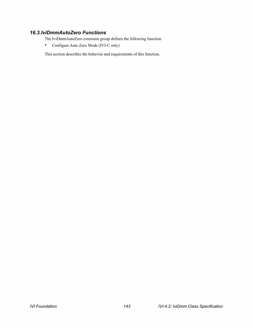
16.3.IviDmmAutoZero Functions The IviDmmAutoZero extension group defines the following function: • Configure Auto Zero Mode (IVI-C only)
This section describes the behavior and requirements of this function.
IVI Foundation ! IVI-4.2: IviDmm Class Specification 143
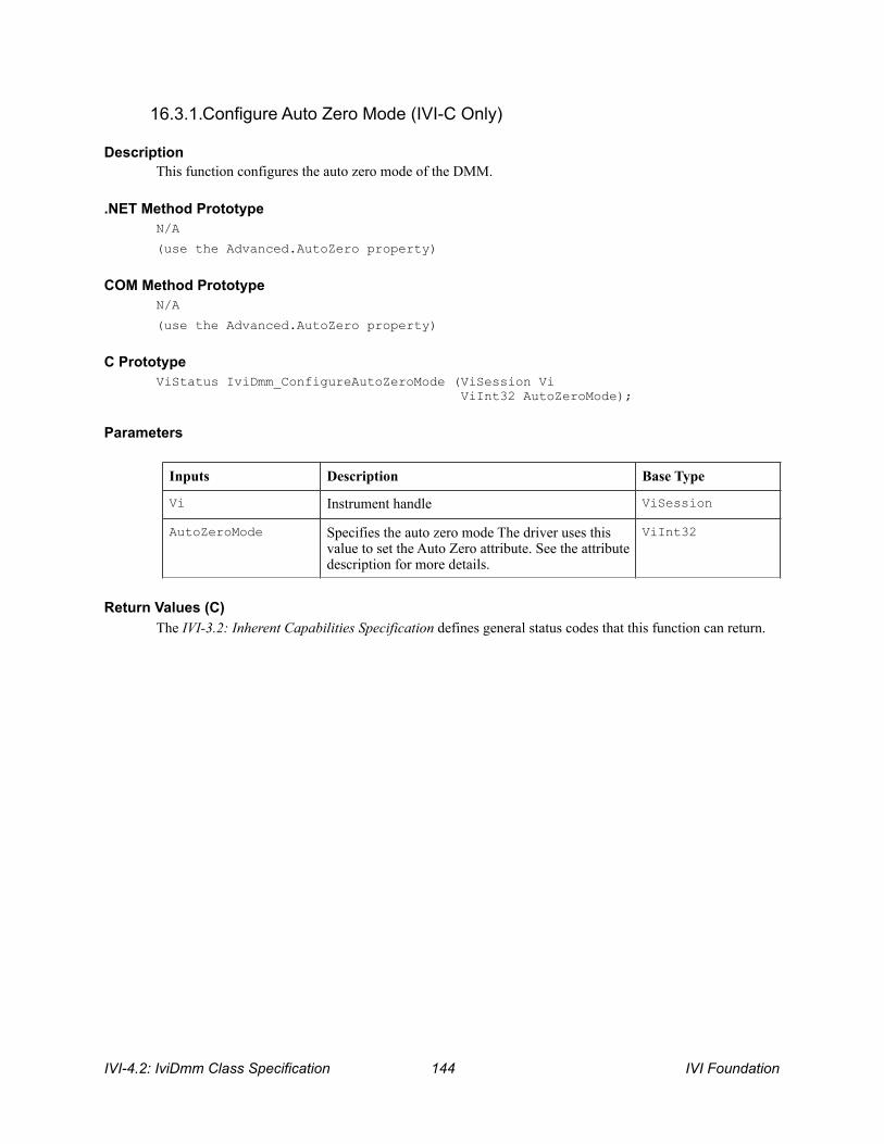
16.3.1.Configure Auto Zero Mode (IVI-C Only)
Description This function configures the auto zero mode of the DMM.
.NET Method Prototype N/A
(use the Advanced.AutoZero property)
COM Method Prototype N/A
(use the Advanced.AutoZero property)
C Prototype ViStatus IviDmm_ConfigureAutoZeroMode (ViSession Vi ViInt32 AutoZeroMode);
Parameters
Return Values (C) The IVI-3.2: Inherent Capabilities Specification defines general status codes that this function can return.
Inputs Description Base Type
Vi Instrument handle ViSession
AutoZeroMode Specifies the auto zero mode The driver uses this value to set the Auto Zero attribute. See the attribute description for more details.
ViInt32
IVI-4.2: IviDmm Class Specification ! IVI Foundation 144

16.4.IviDmmAutoZero Behavior Model The IviDmmAutoZero extension group follows the same behavior model as the IviDmmBase capability group described in Section 4.4, IviDmmBase Behavior Model.
IVI Foundation ! IVI-4.2: IviDmm Class Specification 145

17.IviDmmPowerLineFrequency Extension Group
17.1.IviDmmPowerLineFrequency Extension Group Overview The IviDmmPowerLineFrequency extension supports DMMs with the capability to specify the power line frequency.
Special Note To Users Typically the specific driver disables extension groups that the application program does not explicitly use or enable. The IviDmmPowerLineFrequency extension capability group affects the behavior of the instrument regardless of the value of the Powerline Freq attribute. It is not possible for the specific driver to disable this extension capability group.
Therefore, it is the responsibility of the user to ensure that the power line frequency is correct for their application. Most DMMs do not have a programmable power line frequency and do not implement the IviDmmPowerLineFrequency extension capability group. Users should avoid using the IviDmmPowerLineFrequency extension group in their test program source code so that they can maximize the set of instruments that they can use interchangeably.
For instrument drivers that implement the IviDmmPowerLineFrequency extension, the user can set the value of the Powerline Freq attribute in the IVI configuration file. For instruments that do not implement the IviDmmPowerLineFrequency extension group, the user must ensure that their instrument is set to use the correct power line frequency. Users can manually change the power line frequency setting on most DMMs by means of a switch on the instrument’s back panel.
17.2.IviDmmPowerLineFrequency Attributes The IviDmmPowerLineFrequency extension group defines the following attribute: • Powerline Frequency
This section describes the behavior and requirements of this attribute. The actual value for each attribute ID is defined in Section 18, IviDmm Attribute ID Definitions.
IVI-4.2: IviDmm Class Specification ! IVI Foundation 146

17.2.1.Powerline Frequency
.NET Property Name Advanced.PowerlineFrequency
COM Property Name Advanced.PowerlineFrequency
C Constant Name IVIDMM_ATTR_POWERLINE_FREQ
Description Specifies the power line frequency in Hertz.
.NET Exceptions The IVI-3.2: Inherent Capabilities Specification defines general exceptions that may be thrown, and warning events that may be raised, by this property.
Data Type Access Applies To Coercion High Level Functions
ViReal64 R/W N/A None Configure Power Line Frequency
IVI Foundation ! IVI-4.2: IviDmm Class Specification 147

17.3.IviDmmPowerLineFrequency Functions The IviDmmPowerLineFrequency extension group defines the following function: • Configure Power Line Frequency (IVI-C only)
This section describes the behavior and requirements of this function.
IVI-4.2: IviDmm Class Specification ! IVI Foundation 148

17.3.1.Configure Power Line Frequency (IVI-C Only)
Description This function configures the power line frequency of the DMM.
.NET Method Prototype N/A
(use the Advanced.PowerlineFrequency property)
COM Method Prototype N/A
(use the Advanced.PowerlineFrequency property)
C Prototype ViStatus IviDmm_ConfigurePowerLineFrequency (ViSession Vi ViReal64 PowerLineFreq);
Parameters
Return Values (C) The IVI-3.2: Inherent Capabilities Specification defines general status codes that this function can return.
Inputs Description Base Type
Vi Instrument handle ViSession
PowerLineFreq Specifies the power line frequency The driver uses this value to set the Powerline Freq attribute. See the attribute description for more details.
ViReal64
IVI Foundation ! IVI-4.2: IviDmm Class Specification 149

17.4.IviDmmPowerLineFrequency Behavior Model The IviDmmPowerLineFrequency extension group follows the same behavior model as the IviDmmBase capability group described in Section 4.4, IviDmmBase Behavior Model.
IVI-4.2: IviDmm Class Specification ! IVI Foundation 150
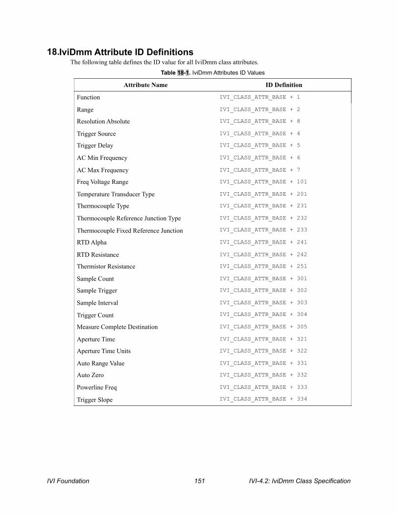
18.IviDmm Attribute ID Definitions The following table defines the ID value for all IviDmm class attributes.
Table 18-1. IviDmm Attributes ID Values
Attribute Name ID Definition
Function IVI_CLASS_ATTR_BASE + 1
Range IVI_CLASS_ATTR_BASE + 2
Resolution Absolute IVI_CLASS_ATTR_BASE + 8
Trigger Source IVI_CLASS_ATTR_BASE + 4
Trigger Delay IVI_CLASS_ATTR_BASE + 5
AC Min Frequency IVI_CLASS_ATTR_BASE + 6
AC Max Frequency IVI_CLASS_ATTR_BASE + 7
Freq Voltage Range IVI_CLASS_ATTR_BASE + 101
Temperature Transducer Type IVI_CLASS_ATTR_BASE + 201
Thermocouple Type IVI_CLASS_ATTR_BASE + 231
Thermocouple Reference Junction Type IVI_CLASS_ATTR_BASE + 232
Thermocouple Fixed Reference Junction IVI_CLASS_ATTR_BASE + 233
RTD Alpha IVI_CLASS_ATTR_BASE + 241
RTD Resistance IVI_CLASS_ATTR_BASE + 242
Thermistor Resistance IVI_CLASS_ATTR_BASE + 251
Sample Count IVI_CLASS_ATTR_BASE + 301
Sample Trigger IVI_CLASS_ATTR_BASE + 302
Sample Interval IVI_CLASS_ATTR_BASE + 303
Trigger Count IVI_CLASS_ATTR_BASE + 304
Measure Complete Destination IVI_CLASS_ATTR_BASE + 305
Aperture Time IVI_CLASS_ATTR_BASE + 321
Aperture Time Units IVI_CLASS_ATTR_BASE + 322
Auto Range Value IVI_CLASS_ATTR_BASE + 331
Auto Zero IVI_CLASS_ATTR_BASE + 332
Powerline Freq IVI_CLASS_ATTR_BASE + 333
Trigger Slope IVI_CLASS_ATTR_BASE + 334
IVI Foundation ! IVI-4.2: IviDmm Class Specification 151

18.1.IviDmm Obsolete Attribute Names The following attribute names are reserved by the IviDmm specification 1.0. Future versions of this specification cannot use these names: • Resolution
18.2.IviDmm Obsolete Attribute ID Values The following attribute ID values are reserved by the IviDmm specification 1.0. Future versions of this specification cannot use these values: • IVI_CLASS_ATTR_BASE + 3
IVI-4.2: IviDmm Class Specification ! IVI Foundation 152

19.IviDmm Attribute Value Definitions This section specifies the actual value for each defined attribute value.
Aperture Time Units
Auto Range (For C and COM, see value definitions for Range.)
Auto Zero
Value Name Language Identifier Actual Value
Seconds .NET Seconds 0
C IVIDMM_VAL_SECONDS 0
COM IviDmmApertureSeconds 0
Power Line Cycles .NET PowerlineCycles 1
C IVIDMM_VAL_POWER_LINE_CYCLES 1
COM IviDmmAperturePowerLineCycles 1
Value Name Language Identifier Actual Value
Auto Off .NET Auto.Off 0
Auto On .NET Auto.On 1
Auto Once .NET Auto.Once 2
Value Name Language Identifier Actual Value
Auto Zero Off .NET Auto.Off 0
C IVIDMM_VAL_AUTO_ZERO_OFF 0
COM IviDmmAutoZeroOff 0
Auto Zero On .NET Auto.On 1
C IVIDMM_VAL_AUTO_ZERO_ON 1
COM IviDmmAutoZeroOn 1
Auto Zero Once .NET Auto.Once 2
C IVIDMM_VAL_AUTO_ZERO_ONCE 2
COM IviDmmAutoZeroOnce 2
Auto Zero Class Extension Base
C IVIDMM_VAL_AUTO_ZERO_CLASS_EXT_BASE 100
IVI Foundation ! IVI-4.2: IviDmm Class Specification 153

Frequency Voltage Range
Function
Auto Zero Specific Extension Base
C IVIDMM_VAL_AUTO_ZERO_SPECIFIC_EXT_BASE
1000
COM N/A N/A
.NET N/A N/A
Value Name Language Identifier Actual Value
Value Name Language Identifier Actual Value
Auto Range On .NET Auto.On 1
C IVIDMM_VAL_AUTO_RANGE_ON -1.0
COM IviDmmFrequencyVoltageRangeAutoRangeOn
-1.0
Auto Range Off .NET Auto.Off 0
C IVIDMM_VAL_AUTO_RANGE_OFF -2.0
COM IviDmmFrequencyVoltageRangeAutoRangeOff
-2.0
Frequency Volt Range Class Extension Base
C IVIDMM_VAL_FREQ_VOLT_RANGE_CLASS_EXT_BASE
-100.0
Frequency Volt Range Specific Extension Base
C IVIDMM_VAL_FREQ_VOLT_RANGE_SPECIFIC_EXT_BASE
-1000.0
COM N/A -1000.0
Value Name Language Identifier Actual Value
DC Volts .NET DCVolts 0
C IVIDMM_VAL_DC_VOLTS 1
COM IviDmmFunctionDCVolts 1
AC Volts .NET ACVolts 1
C IVIDMM_VAL_AC_VOLTS 2
COM IviDmmFunctionACVolts 2
DC Current .NET DCCurrent 2
C IVIDMM_VAL_DC_CURRENT 3
COM IviDmmFunctionDCCurrent 3
IVI-4.2: IviDmm Class Specification ! IVI Foundation 154
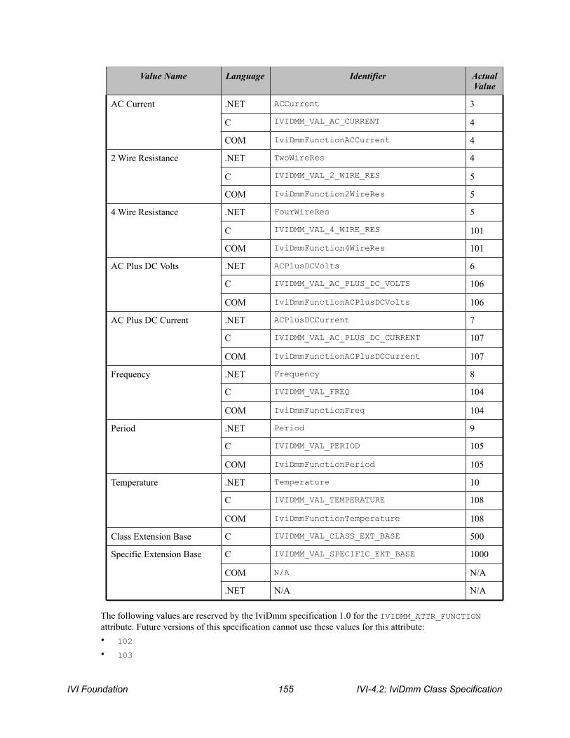
The following values are reserved by the IviDmm specification 1.0 for the IVIDMM_ATTR_FUNCTION attribute. Future versions of this specification cannot use these values for this attribute: • 102
• 103
AC Current .NET ACCurrent 3
C IVIDMM_VAL_AC_CURRENT 4
COM IviDmmFunctionACCurrent 4
2 Wire Resistance .NET TwoWireRes 4
C IVIDMM_VAL_2_WIRE_RES 5
COM IviDmmFunction2WireRes 5
4 Wire Resistance .NET FourWireRes 5
C IVIDMM_VAL_4_WIRE_RES 101
COM IviDmmFunction4WireRes 101
AC Plus DC Volts .NET ACPlusDCVolts 6
C IVIDMM_VAL_AC_PLUS_DC_VOLTS 106
COM IviDmmFunctionACPlusDCVolts 106
AC Plus DC Current .NET ACPlusDCCurrent 7
C IVIDMM_VAL_AC_PLUS_DC_CURRENT 107
COM IviDmmFunctionACPlusDCCurrent 107
Frequency .NET Frequency 8
C IVIDMM_VAL_FREQ 104
COM IviDmmFunctionFreq 104
Period .NET Period 9
C IVIDMM_VAL_PERIOD 105
COM IviDmmFunctionPeriod 105
Temperature .NET Temperature 10
C IVIDMM_VAL_TEMPERATURE 108
COM IviDmmFunctionTemperature 108
Class Extension Base C IVIDMM_VAL_CLASS_EXT_BASE 500
Specific Extension Base C IVIDMM_VAL_SPECIFIC_EXT_BASE 1000
COM N/A N/A
.NET N/A N/A
Value Name Language Identifier Actual Value
IVI Foundation ! IVI-4.2: IviDmm Class Specification 155

• 109
• 110
• 111
IVI-4.2: IviDmm Class Specification ! IVI Foundation 156

Measure Complete Destination
IVI Foundation ! IVI-4.2: IviDmm Class Specification 157

Value Name Language Identifier Actual Value
None C IVIDMM_VAL_NONE -1
COM IviDmmMeasCompleteDestNone -1
External C IVIDMM_VAL_EXTERNAL 2
COM IviDmmMeasCompleteDestExternal 2
TTL0 C IVIDMM_VAL_TTL0 111
COM IviDmmMeasCompleteDestTTL0 111
TTL1 C IVIDMM_VAL_TTL1 112
COM IviDmmMeasCompleteDestTTL1 112
TTL2 C IVIDMM_VAL_TTL2 113
COM IviDmmMeasCompleteDestTTL2 113
TTL3 C IVIDMM_VAL_TTL3 114
COM IviDmmMeasCompleteDestTTL3 114
TTL4 C IVIDMM_VAL_TTL4 115
COM IviDmmMeasCompleteDestTTL4 115
TTL5 C IVIDMM_VAL_TTL5 116
COM IviDmmMeasCompleteDestTTL5 116
TTL6 C IVIDMM_VAL_TTL6 117
COM IviDmmMeasCompleteDestTTL6 117
TTL7 C IVIDMM_VAL_TTL7 118
COM IviDmmMeasCompleteDestTTL7 118
ECL0 C IVIDMM_VAL_ECL0 119
COM IviDmmMeasCompleteDestECL0 119
ECL1 C IVIDMM_VAL_ECL1 120
COM IviDmmMeasCompleteDestECL1 120
PXI Star C IVIDMM_VAL_PXI_STAR 131
COM IviDmmMeasCompleteDestPXIStar 131
RTSI 0 C IVIDMM_VAL_RTSI_0 140
COM IviDmmMeasCompleteDestRTSI0 140
RTSI 1 C IVIDMM_VAL_RTSI_1 141
COM IviDmmMeasCompleteDestRTSI1 141
RTSI 2 C IVIDMM_VAL_RTSI_2 142
IVI-4.2: IviDmm Class Specification ! IVI Foundation 158

Range
Sample Trigger
COM IviDmmMeasCompleteDestRTSI2 142
RTSI 3 C IVIDMM_VAL_RTSI_3 143
COM IviDmmMeasCompleteDestRTSI3 143
RTSI 4 C IVIDMM_VAL_RTSI_4 144
COM IviDmmMeasCompleteDestRTSI4 144
RTSI 5 C IVIDMM_VAL_RTSI_5 145
COM IviDmmMeasCompleteDestRTSI5 145
RTSI 6 C IVIDMM_VAL_RTSI_6 146
COM IviDmmMeasCompleteDestRTSI6 146
Trigger Source Class Extension Base
C IVIDMM_VAL_TRIGGER_SOURCE_CLASS_EXT_BASE
500
Trigger Source Specific Extension Base
C IVIDMM_VAL_TRIGGER_SOURCE_SPECIFIC_EXT_BASE
1000
COM N/A 1000
Value Name Language Identifier Actual Value
Value Name Language Identifier Actual Value
Auto Range On C IVIDMM_VAL_AUTO_RANGE_ON -1.0
COM IviDmmAutoRangeOn -1.0
Auto Range Off C IVIDMM_VAL_AUTO_RANGE_OFF -2.0
COM IviDmmAutoRangeOff -2.0
Auto Range Once C IVIDMM_VAL_AUTO_RANGE_ONCE -3.0
COM IviDmmAutoRangeOnce -3.0
Range Class Extension Base
C IVIDMM_VAL_RANGE_CLASS_EXT_BASE -100.0
Range Specific Extension Base
C IVIDMM_VAL_RANGE_SPECIFIC_EXT_BASE -1000.0
COM N/A N/A
.NET N/A N/A
IVI Foundation ! IVI-4.2: IviDmm Class Specification 159
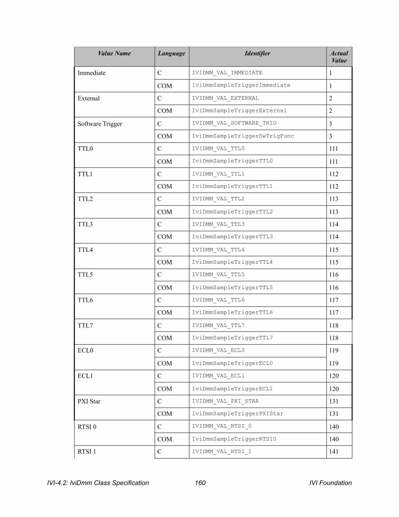
Value Name Language Identifier Actual Value
Immediate C IVIDMM_VAL_IMMEDIATE 1
COM IviDmmSampleTriggerImmediate 1
External C IVIDMM_VAL_EXTERNAL 2
COM IviDmmSampleTriggerExternal 2
Software Trigger C IVIDMM_VAL_SOFTWARE_TRIG 3
COM IviDmmSampleTriggerSwTrigFunc 3
TTL0 C IVIDMM_VAL_TTL0 111
COM IviDmmSampleTriggerTTL0 111
TTL1 C IVIDMM_VAL_TTL1 112
COM IviDmmSampleTriggerTTL1 112
TTL2 C IVIDMM_VAL_TTL2 113
COM IviDmmSampleTriggerTTL2 113
TTL3 C IVIDMM_VAL_TTL3 114
COM IviDmmSampleTriggerTTL3 114
TTL4 C IVIDMM_VAL_TTL4 115
COM IviDmmSampleTriggerTTL4 115
TTL5 C IVIDMM_VAL_TTL5 116
COM IviDmmSampleTriggerTTL5 116
TTL6 C IVIDMM_VAL_TTL6 117
COM IviDmmSampleTriggerTTL6 117
TTL7 C IVIDMM_VAL_TTL7 118
COM IviDmmSampleTriggerTTL7 118
ECL0 C IVIDMM_VAL_ECL0 119
COM IviDmmSampleTriggerECL0 119
ECL1 C IVIDMM_VAL_ECL1 120
COM IviDmmSampleTriggerECL1 120
PXI Star C IVIDMM_VAL_PXI_STAR 131
COM IviDmmSampleTriggerPXIStar 131
RTSI 0 C IVIDMM_VAL_RTSI_0 140
COM IviDmmSampleTriggerRTSI0 140
RTSI 1 C IVIDMM_VAL_RTSI_1 141
IVI-4.2: IviDmm Class Specification ! IVI Foundation 160

The following values are reserved by the IviDmm specification 1.0 for the Sample Trigger attribute. Future versions of this specification cannot use these values: • 101
Thermocouple Reference Junction Type
COM IviDmmSampleTriggerRTSI1 141
RTSI 2 C IVIDMM_VAL_RTSI_2 142
COM IviDmmSampleTriggerRTSI2 142
RTSI 3 C IVIDMM_VAL_RTSI_3 143
COM IviDmmSampleTriggerRTSI3 143
RTSI 4 C IVIDMM_VAL_RTSI_4 144
COM IviDmmSampleTriggerRTSI4 144
RTSI 5 C IVIDMM_VAL_RTSI_5 145
COM IviDmmSampleTriggerRTSI5 145
RTSI 6 C IVIDMM_VAL_RTSI_6 146
COM IviDmmSampleTriggerRTSI6 146
Interval C IVIDMM_VAL_INTERVAL 10
COM IviDmmSampleTriggerInterval 10
Trigger Source Class Extension Base
C IVIDMM_VAL_TRIGGER_SOURCE_CLASS_EXT_BASE
500
Trigger Source Specific Extension Base
C IVIDMM_VAL_TRIGGER_SOURCE_SPECIFIC_EXT_BASE
1000
COM N/A N/A
Value Name Language Identifier Actual Value
Value Name Language Identifier Actual Value
Thermocouple Reference Junction Internal
.NET Internal 0
C IVIDMM_VAL_TEMP_REF_JUNC_INTERNAL 1
COM IviDmmRefJunctionTypeInternal 1
Thermocouple Reference Junction Fixed
.NET Fixed 1
C IVIDMM_VAL_TEMP_REF_JUNC_FIXED 2
COM IviDmmRefJunctionTypeFixed 2
Reference Junction Class Extension Base
C IVIDMM_VAL_TEMP_REF_JUNC_CLASS_EXT_BASE
100
IVI Foundation ! IVI-4.2: IviDmm Class Specification 161
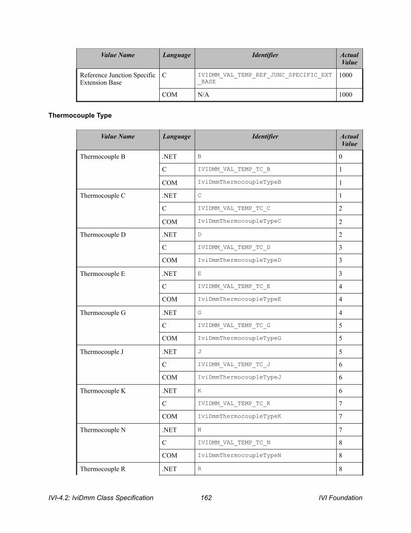
Thermocouple Type
Reference Junction Specific Extension Base
C IVIDMM_VAL_TEMP_REF_JUNC_SPECIFIC_EXT_BASE
1000
COM N/A 1000
Value Name Language Identifier Actual Value
Value Name Language Identifier Actual Value
Thermocouple B .NET B 0
C IVIDMM_VAL_TEMP_TC_B 1
COM IviDmmThermocoupleTypeB 1
Thermocouple C .NET C 1
C IVIDMM_VAL_TEMP_TC_C 2
COM IviDmmThermocoupleTypeC 2
Thermocouple D .NET D 2
C IVIDMM_VAL_TEMP_TC_D 3
COM IviDmmThermocoupleTypeD 3
Thermocouple E .NET E 3
C IVIDMM_VAL_TEMP_TC_E 4
COM IviDmmThermocoupleTypeE 4
Thermocouple G .NET G 4
C IVIDMM_VAL_TEMP_TC_G 5
COM IviDmmThermocoupleTypeG 5
Thermocouple J .NET J 5
C IVIDMM_VAL_TEMP_TC_J 6
COM IviDmmThermocoupleTypeJ 6
Thermocouple K .NET K 6
C IVIDMM_VAL_TEMP_TC_K 7
COM IviDmmThermocoupleTypeK 7
Thermocouple N .NET N 7
C IVIDMM_VAL_TEMP_TC_N 8
COM IviDmmThermocoupleTypeN 8
Thermocouple R .NET R 8
IVI-4.2: IviDmm Class Specification ! IVI Foundation 162

Temperature Transducer Type
C IVIDMM_VAL_TEMP_TC_R 9
COM IviDmmThermocoupleTypeR 9
Thermocouple S .NET S 9
C IVIDMM_VAL_TEMP_TC_S 10
COM IviDmmThermocoupleTypeS 10
Thermocouple T .NET T 10
C IVIDMM_VAL_TEMP_TC_T 11
COM IviDmmThermocoupleTypeT 11
Thermocouple U .NET U 11
C IVIDMM_VAL_TEMP_TC_U 12
COM IviDmmThermocoupleTypeU 12
Thermocouple V .NET V 12
C IVIDMM_VAL_TEMP_TC_V 13
COM IviDmmThermocoupleTypeV 13
Thermocouple Type Class Extension Base
C IVIDMM_VAL_TEMP_TC_TYPE_CLASS_EXT_BASE
100
Thermocouple Type Specific Extension Base
C IVIDMM_VAL_TEMP_TC_TYPE_SPECIFIC_EXT_BASE
1000
COM N/A 1000
Value Name Language Identifier Actual Value
Value Name Language Identifier Actual Value
Thermocouple .NET Thermocouple 0
C IVIDMM_VAL_THERMOCOUPLE 1
COM IviDmmTransducerTypeThermocouple 1
Thermistor .NET Thermistor 1
C IVIDMM_VAL_THERMISTOR 2
COM IviDmmTransducerTypeThermistor 2
2 Wire RTD .NET TwoWireRtd 2
C IVIDMM_VAL_2_WIRE_RTD 3
COM IviDmmTransducerType2WireRtd 3
4 Wire RTD .NET FourWireRtd 3
IVI Foundation ! IVI-4.2: IviDmm Class Specification 163

Trigger Delay
Trigger Slope
C IVIDMM_VAL_4_WIRE_RTD 4
COM IviDmmTransducerType4WireRtd 4
Transducer Class Extension Base
C IVIDMM_VAL_TRANSDUCER_CLASS_EXT_BASE 100
Transducer Specific Extension Base
C IVIDMM_VAL_TRANSDUCER_SPECIFIC_EXT_BASE
1000
COM N/A 1000
Value Name Language Identifier Actual Value
Value Name Language Identifier Actual Value
Auto Delay On C IVIDMM_VAL_AUTO_DELAY_ON -1.0
COM IviDmmTriggerDelayAutoDelayOn -1.0
Auto Delay Off C IVIDMM_VAL_AUTO_DELAY_OFF -2.0
COM IviDmmTriggerDelayAutoDelayOff -2.0
Trigger Delay Class Extension Base
C IVIDMM_VAL_TRIGGER_DELAY_CLASS_EXT_BASE
-100.0
Trigger Delay Specific Extension Base
C IVIDMM_VAL_TRIGGER_DELAY_SPECIFIC_EXT_BASE
-1000.0
COM N/A -1000.0
Value Name Language Identifier Actual Value
Positive .NET Slope.Positive 0
C IVIDMM_VAL_POSITIVE 0
COM IviDmmTriggerSlopePositive 0
Negative .NET Slope.Negative 1
C IVIDMM_VAL_NEGATIVE 1
COM IviDmmTriggerSlopeNegative 1
Trigger Slope Class Extension Base
C IVIDMM_VAL_TRIGGER_SLOPE_CLASS_EXT_BASE
100
Trigger Slope Specific Extension Base
C IVIDMM_VAL_TRIGGER_SLOPE_SPECIFIC_EXT_BASE
1000
IVI-4.2: IviDmm Class Specification ! IVI Foundation 164
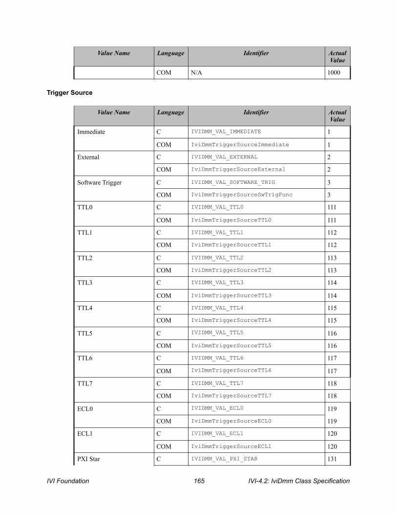
Trigger Source
Extension Base
COM N/A 1000
Value Name Language Identifier Actual Value
Value Name Language Identifier Actual Value
Immediate C IVIDMM_VAL_IMMEDIATE 1
COM IviDmmTriggerSourceImmediate 1
External C IVIDMM_VAL_EXTERNAL 2
COM IviDmmTriggerSourceExternal 2
Software Trigger C IVIDMM_VAL_SOFTWARE_TRIG 3
COM IviDmmTriggerSourceSwTrigFunc 3
TTL0 C IVIDMM_VAL_TTL0 111
COM IviDmmTriggerSourceTTL0 111
TTL1 C IVIDMM_VAL_TTL1 112
COM IviDmmTriggerSourceTTL1 112
TTL2 C IVIDMM_VAL_TTL2 113
COM IviDmmTriggerSourceTTL2 113
TTL3 C IVIDMM_VAL_TTL3 114
COM IviDmmTriggerSourceTTL3 114
TTL4 C IVIDMM_VAL_TTL4 115
COM IviDmmTriggerSourceTTL4 115
TTL5 C IVIDMM_VAL_TTL5 116
COM IviDmmTriggerSourceTTL5 116
TTL6 C IVIDMM_VAL_TTL6 117
COM IviDmmTriggerSourceTTL6 117
TTL7 C IVIDMM_VAL_TTL7 118
COM IviDmmTriggerSourceTTL7 118
ECL0 C IVIDMM_VAL_ECL0 119
COM IviDmmTriggerSourceECL0 119
ECL1 C IVIDMM_VAL_ECL1 120
COM IviDmmTriggerSourceECL1 120
PXI Star C IVIDMM_VAL_PXI_STAR 131
IVI Foundation ! IVI-4.2: IviDmm Class Specification 165

The following values are reserved by the IviDmm specification 1.0 for the IVIDMM_ATTR_TRIGGER_SOURCE attribute. Future versions of this specification cannot use these values: • 101
19.1.IviDmm Obsolete Attribute Value Names The following attribute value names are reserved by the IviDmm specification 1.0. Future versions of this specification cannot use these names: • IVIDMM_VAL_DIODE
• IVIDMM_VAL_CONTINUITY
• IVIDMM_VAL_TEMP_C
• IVIDMM_VAL_TEMP_F
• IVIDMM_VAL_SIEMENS
• IVIDMM_VAL_COULOMBS
• IVIDMM_VAL_3_5_DIGITS
• IVIDMM_VAL_4_DIGITS
• IVIDMM_VAL_4_5_DIGITS
COM IviDmmTriggerSourcePXIStar 131
RTSI 0 C IVIDMM_VAL_RTSI_0 140
COM IviDmmTriggerSourceRTSI0 140
RTSI 1 C IVIDMM_VAL_RTSI_1 141
COM IviDmmTriggerSourceRTSI1 141
RTSI 2 C IVIDMM_VAL_RTSI_2 142
COM IviDmmTriggerSourceRTSI2 142
RTSI 3 C IVIDMM_VAL_RTSI_3 143
COM IviDmmTriggerSourceRTSI3 143
RTSI 4 C IVIDMM_VAL_RTSI_4 144
COM IviDmmTriggerSourceRTSI4 144
RTSI 5 C IVIDMM_VAL_RTSI_5 145
COM IviDmmTriggerSourceRTSI5 145
RTSI 6 C IVIDMM_VAL_RTSI_6 146
COM IviDmmTriggerSourceRTSI6 146
Trigger Source Class Extension Base
C IVIDMM_VAL_TRIGGER_SOURCE_CLASS_EXT_BASE
500
Trigger Source Specific Extension Base
C IVIDMM_VAL_TRIGGER_SOURCE_SPECIFIC_EXT_BASE
1000
COM N/A 1000
Value Name Language Identifier Actual Value
IVI-4.2: IviDmm Class Specification ! IVI Foundation 166
• IVIDMM_VAL_5_DIGITS
• IVIDMM_VAL_5_5_DIGITS
• IVIDMM_VAL_6_DIGITS
• IVIDMM_VAL_6_5_DIGITS
• IVIDMM_VAL_7_DIGITS
• IVIDMM_VAL_7_5_DIGITS
• IVIDMM_VAL_50_HERTZ
• IVIDMM_VAL_60_HERTZ
• IVIDMM_VAL_400_HERTZ
• IVIDMM_VAL_GPIB_GET
• IVIDMM_VAL_SW_TRIG_FUNC
IVI Foundation ! IVI-4.2: IviDmm Class Specification 167

20.IviDmm Function Parameter Value Definitions This section specifies the actual values for each function parameter that defines values.
Read
Fetch Parameter: MaxTimeMilliseconds Same as defined for the MaxTimeMilliseconds parameter of the IviDmm_Read function.
Read Multi Point Parameter: MaxTimeMilliseconds Same as defined for the MaxTimeMilliseconds parameter of the IviDmm_Read function.
IviDmm_FetchMultiPoint Parameter: MaxTimeMilliseconds Same as defined for the MaxTimeMilliseconds parameter of the IviDmm_Read function.
Parameter: MaxTimeMilliseconds
Value Name Language Identifier Actual (hex)
Max Time Immediate C IVIDMM_VAL_MAX_TIME_IMMEDIATE 0
COM IviDmmMaxTimeImmediate 0
Max Time Infinite C IVIDMM_VAL_MAX_TIME_INFINITE 0xFFFFFFFF
COM IviDmmMaxTimeInfinite 0xFFFFFFFF
IVI-4.2: IviDmm Class Specification ! IVI Foundation 168
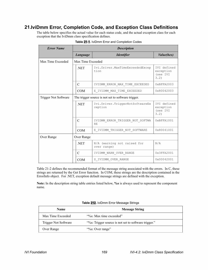
21.IviDmm Error, Completion Code, and Exception Class Definitions The table below specifies the actual value for each status code, and the actual exception class for each exception that the IviDmm class specification defines.
Table 21-2 defines the recommended format of the message string associated with the errors. In C, these strings are returned by the Get Error function. In COM, these strings are the description contained in the ErrorInfo object. For .NET, exception default message strings are defined with the exception.
Note: In the description string table entries listed below, %s is always used to represent the component name.
Table 21-1. IviDmm Error and Completion Codes
Error Name Description
Language Identifier Value(hex)
Max Time Exceeded Max Time Exceeded
.NET Ivi.Driver.MaxTimeExceededException
IVI defined exception (see IVI 3.2)
C IVIDMM_ERROR_MAX_TIME_EXCEEDED 0xBFFA2003
COM E_IVIDMM_MAX_TIME_EXCEEDED 0x80042003
Trigger Not Software The trigger source is not set to software trigger.
.NET Ivi.Driver.TriggerNotSoftwareException
IVI defined exception (see IVI 3.2)
C IVIDMM_ERROR_TRIGGER_NOT_SOFTWARE
0xBFFA1001
COM E_IVIDMM_TRIGGER_NOT_SOFTWARE 0x80041001
Over Range Over Range
.NET N/A (warning not raised for over range)
N/A
C IVIDMM_WARN_OVER_RANGE 0x3FFA2001
COM S_IVIDMM_OVER_RANGE 0x00042001
Table 212. IviDmm Error Message Strings
Name Message String
Max Time Exceeded “%s: Max time exceeded”
Trigger Not Software “%s: Trigger source is not set to software trigger.”
Over Range “%s: Over range”
IVI Foundation ! IVI-4.2: IviDmm Class Specification 169

21.1.IviDmm Obsolete Error and Completion Code Names The following error and completion codes names are reserved by the IviDmm specification 1.0. Future versions of this specification cannot use these names: • Accuracy Unknown • Accuracy Unknown While Autoranging
21.2.IviDmm Obsolete Error and Completion Code Values The following error and completion codes values are reserved by the IviDmm specification 1.0. Future versions of this specification cannot use these values: • IVI_CLASS_ERROR_BASE + 1
• IVI_CLASS_ERROR_BASE + 2
IVI-4.2: IviDmm Class Specification ! IVI Foundation 170

22.IviDmm Hierarchies
22.1.IviDmm ,NET Hierarchy
The full IviDmm.NET Hierarchy includes the Inherent Capabilities Hierarchy as defined in Section 4.1, .NET Inherent Capabilities of IVI-3.2: Ineherent Capabilities Specification. To avoid redundancy, it is omitted from Table 221. IviDmm.NETHierarchy.
Table 221. IviDmm.NETHierarchy
.NET Interface Hierarchy Generic Name Type
Configure Configure Measurement M
MeasurementFunction Function P
Range Range P
AutoRange Auto Range P
Resolution Resolution Absolute P
AC
ConfigureBandwidth Configure AC Bandwidth M
FrequencyMax AC Max Freq P
FrequencyMin AC Min Freq P
Advanced
ApertureTime Aperture Time P
ApertureTimeUnits Aperture Time Units P
AutoZero Auto Zero P
PowerlineFrequency Powerline Freq P
Frequency
VoltageRange Freq Voltage Range P
VoltageAutoRange Voltage Auto Range P
Measurement
Initiate Initiate M
Abort Abort M
Fetch Fetch M
FetchMultiPoint Fetch Multi Point M
Read Read M
ReadMultiPoint Read Multi Point M
SendSoftwareTrigger Send Software Trigger M
Temperature
IVI Foundation ! IVI-4.2: IviDmm Class Specification 171

TransducerType Temperature Transducer Type P
Rtd
Configure Configure RTD M
Alpha Temperature RTD Alpha P
Resistance Temperature RTD Resistance P
Thermocouple
Configure Configure Thermocouple M
FixedReferenceJunction Temp TC Fixed Reference Junction P
ReferenceJunctionType Temp TC Reference Junction Type P
Type Temp TC Type P
Thermistor
Resistance Temperature Thermistor Resistance P
Trigger
Configure Configure Trigger M
Slope Trigger Slope P
Delay Trigger Delay P
DelayAuto Trigger Delay Auto P
MeasurementCompleteDestination Measurement Complete Dest P
Source Trigger Source P
MultiPoint
Configure Configure Multi Point M
Count Trigger Count P
SampleCount Sample Count P
SampleInterval Sample Interval P
SampleTrigger Sample Trigger P
Table 221. IviDmm.NETHierarchy
.NET Interface Hierarchy Generic Name Type
IVI-4.2: IviDmm Class Specification ! IVI Foundation 172
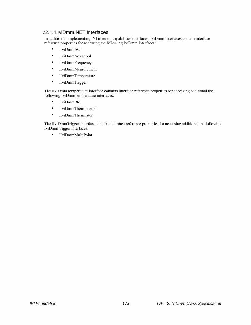
22.1.1.IviDmm.NET Interfaces In addition to implementing IVI inherent capabilities interfaces, IviDmm-interfaces contain interface reference properties for accessing the following IviDmm interfaces:
• IIviDmmAC • IIviDmmAdvanced • IIviDmmFrequency • IIviDmmMeasurement • IIviDmmTemperature • IIviDmmTrigger
The IIviDmmTemperature interface contains interface reference properties for accessing additional the following IviDmm temperature interfaces:
• IIviDmmRtd • IIviDmmThermocouple • IIviDmmThermistor
The IIviDmmTrigger interface contains interface reference properties for accessing additional the following IviDmm trigger interfaces:
• IIviDmmMultiPoint
IVI Foundation ! IVI-4.2: IviDmm Class Specification 173

22.1.2..NET Interface Reference Properties Interface reference properties are used to navigate the IviDmm .NET hierarchy. This section describes the interface reference properties that the IIviDmm, IIviDmmTemperature, and IIviDmmTrigger interfaces define.
Data Type .NET Property Name
IIviDmmAC AC
IIviDmmAdvanced Advanced
IIviDmmFrequency Frequency
IIviDmmMeasurement Measurement
IIviDmmTemperature Temperature
IIviDmmTrigger Trigger
IIviDmmRtd Temperature.Rtd
IIviDmmThermocouple Temperature.Thermocouple
IIviDmmThermistor Temperature.Thermistor
IIviDmmMultiPoint Trigger.MultiPoint
IVI-4.2: IviDmm Class Specification ! IVI Foundation 174

22.2.IviDmm COM Hierarchy
The full IviDmm COM Hierarchy includes the Inherent Capabilities Hierarchy as defined in Section 4.2, COM Inherent Capabilities of IVI-3.2: Ineherent Capabilities Specification. To avoid redundancy, it is omitted from Table 2-1..
Table 222. IviDmm COM Hierarchy
COM Interface Hierarchy Generic Name Type
Configure Configure Measurement M
Function Function P
Range Range P
Resolution Resolution Absolute P
AC
ConfigureBandwidth Configure AC Bandwidth M
FrequencyMax AC Max Freq P
FrequencyMin AC Min Freq P
Advanced
ActualRange Auto Range Value P
ApertureTime Aperture Time P
ApertureTimeUnits Aperture Time Units P
AutoZero Auto Zero P
PowerlineFrequency Powerline Freq P
Frequency
VoltageRange Freq Voltage Range P
Measurement
Initiate Initiate M
Abort Abort M
Fetch Fetch M
FetchMultiPoint Fetch Multi Point M
Read Read M
ReadMultiPoint Read Multi Point M
SendSoftwareTrigger Send Software Trigger M
IsOverRange Is Over Range M
Temperature
TransducerType Temperature Transducer Type P
RTD
Configure Configure RTD M
IVI Foundation ! IVI-4.2: IviDmm Class Specification 175
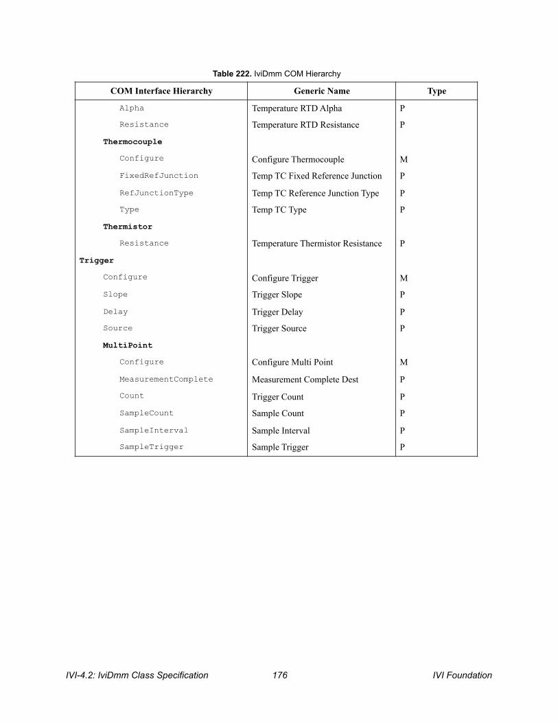
Alpha Temperature RTD Alpha P
Resistance Temperature RTD Resistance P
Thermocouple
Configure Configure Thermocouple M
FixedRefJunction Temp TC Fixed Reference Junction P
RefJunctionType Temp TC Reference Junction Type P
Type Temp TC Type P
Thermistor
Resistance Temperature Thermistor Resistance P
Trigger
Configure Configure Trigger M
Slope Trigger Slope P
Delay Trigger Delay P
Source Trigger Source P
MultiPoint
Configure Configure Multi Point M
MeasurementComplete Measurement Complete Dest P
Count Trigger Count P
SampleCount Sample Count P
SampleInterval Sample Interval P
SampleTrigger Sample Trigger P
Table 222. IviDmm COM Hierarchy
COM Interface Hierarchy Generic Name Type
IVI-4.2: IviDmm Class Specification ! IVI Foundation 176

22.2.1.IviDmm COM Interfaces In addition to implementing IVI inherent capabilities interfaces, IviDmm-interfaces contain interface reference properties for accessing the following IviDmm interfaces:
• IIviDmmAC • IIviDmmAdvanced • IIviDmmFrequency • IIviDmmMeasurement • IIviDmmTemperature • IIviDmmTrigger
The IIviDmmTemperature interface contains interface reference properties for accessing additional the following IviDmm temperature interfaces:
• IIviDmmRTD • IIviDmmThermocouple • IIviDmmThermistor
The IIviDmmTrigger interface contains interface reference properties for accessing additional the following IviDmm trigger interfaces:
• IIviDmmMultiPoint
Table 223. IviDmm lists the interfaces that this specification defines and their GUIDs.
Table 223. IviDmm Interface GUIDs
Interface GUID
IIviDmm {47ed51e8-a398-11d4-ba58-000064657374}
IIviDmmAC {47ed51ec-a398-11d4-ba58-000064657374}
IIviDmmAdvanced {47ed51ed-a398-11d4-ba58-000064657374}
IIviDmmFrequency {47ed51ee-a398-11d4-ba58-000064657374}
IiviDmmMeasurement {47ed51e9-a398-11d4-ba58-000064657374}
IIviDmmTemperature {47ed51ef-a398-11d4-ba58-000064657374}
IIviDmmTrigger {47ed51ea-a398-11d4-ba58-000064657374}
IIviDmmRTD {47ed51f0-a398-11d4-ba58-000064657374}
IIviDmmThermocouple {47ed51f1-a398-11d4-ba58-000064657374}
IIviDmmThermistor {47ed51f2-a398-11d4-ba58-000064657374}
IIviDmmMultiPoint {47ed51eb-a398-11d4-ba58-000064657374}
IVI Foundation ! IVI-4.2: IviDmm Class Specification 177

22.2.2.Interface Reference Properties Interface reference properties are used to navigate the IviDmm COM hierarchy. This section describes the interface reference properties that the IIviDmm, IIviDmmTemperature, and IIviDmmTrigger interfaces define.
22.2.3.IviDmm COM Category The IviDmm class COM Category shall be “IviDmm”, and the Category ID (CATID) shall be {47ed5154-a398-11d4-ba58-000064657374}.
Data Type COM Property Name
IIviDmmAC AC
IIviDmmAdvanced Advanced
IIviDmmFrequency Frequency
IIviDmmMeasurement Measurement
IIviDmmTemperature Temperature
IIviDmmTrigger Trigger
IIviDmmRTD Temperature.RTD
IIviDmmThermocouple Temperature.Thermocouple
IIviDmmThermistor Temperature.Thermistor
IIviDmmMultiPoint Trigger.MultiPoint
IVI-4.2: IviDmm Class Specification ! IVI Foundation 178

22.3.IviDmm C Function Hierarchy The IviDmm class function hierarchy is shown in the following table.
Table 22-1. IviDmm Function Hierarchy
Name or Class Function Name
Configuration…
Configure Measurement IviDmm_ConfigureMeasurement
Specific Measurements…
Configure AC Bandwidth IviDmm_ConfigureACBandwidth
Configure Frequency Voltage Range IviDmm_ConfigureFrequencyVoltageRange
Temperature…
Configure Transducer Type IviDmm_ConfigureTransducerType
Configure Thermocouple IviDmm_ConfigureThermocouple
Configure Fixed Reference Junction IviDmm_ConfigureFixedRefJunction
Configure RTD IviDmm_ConfigureRTD
Configure Thermistor IviDmm_ConfigureThermistor
Trigger…
Configure Trigger IviDmm_ConfigureTrigger
Configure Trigger Slope IviDmm_ConfigureTriggerSlope
MultiPoint…
Configure Multi-Point IviDmm_ConfigureMultiPoint
Configure Measurement Complete Destination
IviDmm_ConfigureMeasCompleteDest
Measurement Operation Options…
Configure Auto Zero Mode IviDmm_ConfigureAutoZeroMode
Configure Power Line Frequency IviDmm_ConfigurePowerLineFrequency
Configuration Information…
Get Auto Range Value IviDmm_GetAutoRangeValue
Get Aperture Time Info IviDmm_GetApertureTimeInfo
Measurement…
Read IviDmm_Read
Read Multi-Point IviDmm_ReadMultiPoint
Low Level Measurement…
Initiate IviDmm_Initiate
Send Software Trigger IviDmm_SendSoftwareTrigger
Fetch IviDmm_Fetch
IVI Foundation ! IVI-4.2: IviDmm Class Specification 179
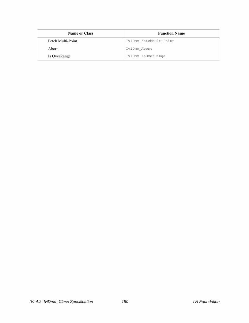
Fetch Multi-Point IviDmm_FetchMultiPoint
Abort IviDmm_Abort
Is OverRange IviDmm_IsOverRange
Name or Class Function Name
IVI-4.2: IviDmm Class Specification ! IVI Foundation 180
22.3.1.Ivi Dmm Obsolete Function Names
The following function names are reserved by the IviDmm specification 1.0. The future versions of this specification cannot use these names: • IviDmm_Configure
• IviDmm_CalculateAccuracy
• IviDmm_SendSWTrigger
IVI Foundation ! IVI-4.2: IviDmm Class Specification 181

22.4.IviDmm C Attribute Hierarchy
The IviDmm class attribute hierarchy is shown in the following table.
Table 224 IviDmm C Attributes Hierarchy
Category or Generic Attribute Name
C Defined Constant
Basic Operation
Function IVIDMM_ATTR_FUNCTION
Range IVIDMM_ATTR_RANGE
Resolution IVIDMM_ATTR_RESOLUTION_ABSOLUTE
Trigger
Trigger Source IVIDMM_ATTR_TRIGGER_SOURCE
Trigger Delay IVIDMM_ATTR_TRIGGER_DELAY
Trigger Slope IVIDMM_ATTR_TRIGGER_SLOPE
AC Measurements
AC Minimum Frequency IVIDMM_ATTR_AC_MIN_FREQ
AC Maximum Frequency IVIDMM_ATTR_AC_MAX_FREQ
Frequency Measurements
Frequency Voltage Range IVIDMM_ATTR_FREQ_VOLTAGE_RANGE
Temperature Measurements
Transducer Type IVIDMM_ATTR_TEMP_TRANSDUCER_TYPE
Thermocouple
Fixed Reference Junction IVIDMM_ATTR_TEMP_TC_FIXED_REF_JUNC
Reference Junction Type IVIDMM_ATTR_TEMP_TC_REF_JUNC_TYPE
Thermocouple Type IVIDMM_ATTR_TEMP_TC_TYPE
Resistance Temperature Device
RTD Resistance IVIDMM_ATTR_TEMP_RTD_RES
RTD Alpha IVIDMM_ATTR_TEMP_RTD_ALPHA
Thermistor
Thermistor Resistance IVIDMM_ATTR_TEMP_THERMISTOR_RES
Multi-Point Acquisition
IVI-4.2: IviDmm Class Specification ! IVI Foundation 182
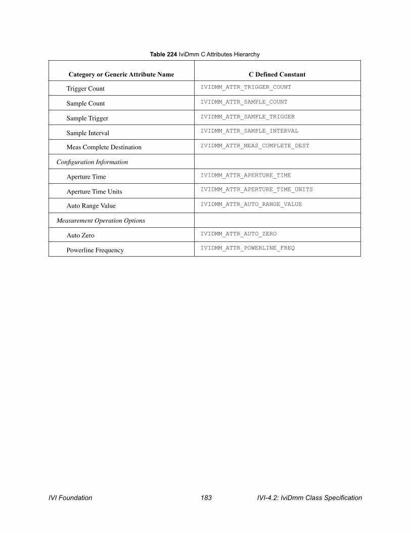
Trigger Count IVIDMM_ATTR_TRIGGER_COUNT
Sample Count IVIDMM_ATTR_SAMPLE_COUNT
Sample Trigger IVIDMM_ATTR_SAMPLE_TRIGGER
Sample Interval IVIDMM_ATTR_SAMPLE_INTERVAL
Meas Complete Destination IVIDMM_ATTR_MEAS_COMPLETE_DEST
Configuration Information
Aperture Time IVIDMM_ATTR_APERTURE_TIME
Aperture Time Units IVIDMM_ATTR_APERTURE_TIME_UNITS
Auto Range Value IVIDMM_ATTR_AUTO_RANGE_VALUE
Measurement Operation Options
Auto Zero IVIDMM_ATTR_AUTO_ZERO
Powerline Frequency IVIDMM_ATTR_POWERLINE_FREQ
Table 224 IviDmm C Attributes Hierarchy
Category or Generic Attribute Name
C Defined Constant
IVI Foundation ! IVI-4.2: IviDmm Class Specification 183

A. Specific Driver Development Guidelines
A.1. Introduction This section describes situations driver developers should be aware of when developing a specific instrument driver that complies with the IviDmm class.
A.2. Disabling Unused Extension Groups Specific drivers are required to disable extension capability groups that an application program does not explicitly use. The specific driver can do so by setting the attributes of an extension capability group to the values that this section recommends. A specific driver can set these values for all extension capability groups when the Prefix_init, Prefix_InitWithOptions, or Prefix_reset functions execute. This assumes that the extension capability groups remain disabled until the application program explicitly uses them. For the large majority of instruments, this assumption is true.
Under certain conditions, a specific driver might have to implement a more complex approach. For some instruments, configuring a capability group might affect instrument settings that correspond to an unused extension capability group. If these instrument settings affect the behavior of the instrument, then this might result in an interchangeability problem. If this can occur, the specific driver must take appropriate action so that the instrument settings that correspond to the unused extension capability group do not affect the behavior of the instrument when the application program performs an operation that might be affected by those settings.
The remainder of this section recommends attribute values that effectively disable each extension capability group.
Disabling the IviDmm Measurement Extension Capability Groups Some measurements that the user selects with the Function require an extension group to further configure the measurement. The values for the Function that require additional extension capability groups are shown in the following table. • IviDmmACMeasurement • IviDmmFrequencyMeasurement • IviDmmTemperatureMeasurement • IviDmmThermocouple • IviDmmResistanceTemperatureDevice • IviDmmThermistor
When the Function is set to one of these values, the corresponding extension capability group affects the behavior of the instruments. Otherwise, the extension capability group does not affect the behavior of the instrument and is effectively disabled. Therefore, this section does not recommend how to disable these extension capability groups.
IVI-4.2: IviDmm Class Specification ! IVI Foundation 184
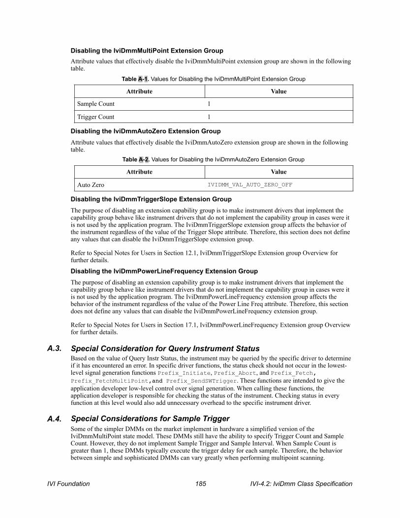
Disabling the IviDmmMultiPoint Extension Group Attribute values that effectively disable the IviDmmMultiPoint extension group are shown in the following table.
Disabling the IviDmmAutoZero Extension Group Attribute values that effectively disable the IviDmmAutoZero extension group are shown in the following table.
Disabling the IviDmmTriggerSlope Extension Group The purpose of disabling an extension capability group is to make instrument drivers that implement the capability group behave like instrument drivers that do not implement the capability group in cases were it is not used by the application program. The IviDmmTriggerSlope extension group affects the behavior of the instrument regardless of the value of the Trigger Slope attribute. Therefore, this section does not define any values that can disable the IviDmmTriggerSlope extension group.
Refer to Special Notes for Users in Section 12.1, IviDmmTriggerSlope Extension group Overview for further details.
Disabling the IviDmmPowerLineFrequency Extension Group The purpose of disabling an extension capability group is to make instrument drivers that implement the capability group behave like instrument drivers that do not implement the capability group in cases were it is not used by the application program. The IviDmmPowerLineFrequency extension group affects the behavior of the instrument regardless of the value of the Power Line Freq attribute. Therefore, this section does not define any values that can disable the IviDmmPowerLineFrequency extension group.
Refer to Special Notes for Users in Section 17.1, IviDmmPowerLineFrequency Extension group Overview for further details.
A.3. Special Consideration for Query Instrument Status Based on the value of Query Instr Status, the instrument may be queried by the specific driver to determine if it has encountered an error. In specific driver functions, the status check should not occur in the lowest-level signal generation functions Prefix_Initiate, Prefix_Abort, and Prefix_Fetch, Prefix_FetchMultiPoint,and Prefix_SendSWTrigger. These functions are intended to give the application developer low-level control over signal generation. When calling these functions, the application developer is responsible for checking the status of the instrument. Checking status in every function at this level would also add unnecessary overhead to the specific instrument driver.
A.4. Special Considerations for Sample Trigger Some of the simpler DMMs on the market implement in hardware a simplified version of the IviDmmMultiPoint state model. These DMMs still have the ability to specify Trigger Count and Sample Count. However, they do not implement Sample Trigger and Sample Interval. When Sample Count is greater than 1, these DMMs typically execute the trigger delay for each sample. Therefore, the behavior between simple and sophisticated DMMs can vary greatly when performing multipoint scanning.
Table A-1. Values for Disabling the IviDmmMultiPoint Extension Group
Attribute Value
Sample Count 1
Trigger Count 1
Table A-2. Values for Disabling the IviDmmAutoZero Extension Group
Attribute Value
Auto Zero IVIDMM_VAL_AUTO_ZERO_OFF
IVI Foundation ! IVI-4.2: IviDmm Class Specification 185
If you implement the IviDmmMultiPoint extension group on instruments that do not have a Sample Trigger, you should do the following to be interchangeable with DMMs that fully support the extension:
1. Implement Sample Trigger with the only supported value Sample Interval.
2. Implement Sample Interval where the only possible value is the present value for Trigger Delay.
3. Set the Trigger Delay attribute to invalidate the Sample Interval attribute.
By following these guidelines, you will maximize interchangeable behavior between all DMMs.
A.5. Special Considerations for Auto Range Value The purpose of the attribute Auto Range Value is to return the range that the instrument has auto-ranged to when the attribute Range is set to Auto Range On. Since the value of Auto Range is likely to change as the input signal changes, drivers that may cache attributes should never cache this attribute.
IVI-4.2: IviDmm Class Specification ! IVI Foundation 186
B. Interchangeability Checking Rules
B.1. Introduction IVI drivers have a feature called interchangeability checking. Interchangeability checking returns a warning when it encounters a situation were the application program might not produce the same behavior when the user attempts to use a different instrument.
B.2. When to Perform Interchangeability Checking Interchangeability checking occurs when all of the following conditions are met: • The Interchange Check attribute is set to True • The user calls one of the following functions:
− Initiate − Read − Read Multi Point
B.3. Interchangeability Checking Rules Interchangeability checking is performed on a capability group basis. When enabled, interchangeability checking is always performed on the base capability group. In addition, interchangeability checking is performed on extension capability groups for which the user has ever set any of the attributes of the group. If the user has never set any attributes of an extension capability group, interchangeability checking is not performed on that group.
In general interchangeability warnings are generated if the following conditions are encountered: • An attribute that affects the behavior of the instrument is not in a state that the user specifies. • The user sets a class driver defined attribute to an instrument-specific value. • The user configures the value of an attribute that the class defines as read-only. In a few cases the class
drivers define read-only attributes that specific drivers might implement as read/write.
The remainder of this section defines additional rules and exceptions for each capability group.
IviDmmBase Capability Group If the Function attribute is set to Temperature, the Resolution Absolute attribute is not required to be in a user specified state.
IviDmmACMeasurement Extension Group If the Function attribute is not set to AC Volts, AC Current, AC Plus DC Volts, or AC Plus DC Current, then the following attributes are not required to be in a user specified state: • AC Min Freq • AC Max Freq
IviDmmFrequencyMeasurement Extension Group If the Function attribute is not set to Frequency or Period, then the Freq Voltage Range attribute is not required to be in a user specified state.
IviDmmTemperatureMeasurement Extension Group If the Function attribute is not set to Temperature, the Temperature Transducer Type attribute is not required to be in a user specified state.
IVI Foundation ! IVI-4.2: IviDmm Class Specification 187
IviDmmThermocouple Extension Group If the Temperature Transducer Type attribute is not set to Thermocouple, then the following attributes are not required to be in a user specified state: • Thermocouple Type • Thermocouple Reference Junction Type • Thermocouple Fixed Reference Junction
IviDmmResistanceTemperatureDevice Extension Group If the Temperature Transducer Type attribute is not set to 2 Wire RTD or 4 Wire RTD, then the following attributes are not required to be in a user specified state: • RTD Alpha • RTD Resistance
IviDmmThermistor Extension Group If the Temperature Transducer Type attribute is not set to Thermistor, the Thermistor Resistance attribute is not required to be in a user specified state.
IviDmmMultiPoint Extension Group 1. If the Sample Count attribute is set to 1, then the following attributes are not required to be in a user
specified state: • Sample Trigger • Sample Interval
2. If the Sample Count attribute is set 1 and the Sample Trigger attribute is set to a value other than Interval, then the Sample Interval attribute is not required to be in a user specified state.
IviDmmTriggerSlope Extension Group No additional interchangeability rules or exceptions are defined for the IviDmmTriggerSlope extension group.
IviDmmSoftwareTrigger Extension Group No additional interchangeability rules or exceptions are defined for the IviDmmSoftwareTrigger extension group.
IviDmmDeviceInfo Extension Group No additional interchangeability rules or exceptions are defined for the IviDmmDeviceInfo extension group.
IviDmmAutoRangeValue Extension Group No additional interchangeability rules or exceptions are defined for the IviDmmAutoRangeValue extension group.
IviDmmAutoZero Extension Group No additional interchangeability rules or exceptions are defined for the IviDmmAutoZero extension group.
IviDmmPowerLineFrequency Extension Group No additional interchangeability rules or exceptions are defined for the IviDmmPowerLineFrequency extension group.
IVI-4.2: IviDmm Class Specification ! IVI Foundation 188


![Information Visualization Research directions in data wrangling: … · XML Template (2011) [10.8.2011–6:17pm] [1–18] K:/IVI/IVI 415994.3d (IVI) [PREPRINTER stage] Research Paper](https://static.documents.pub/doc/80x56/5f90b3a50d01d61bb605ec75/information-visualization-research-directions-in-data-wrangling-xml-template-2011.jpg)


