IV/IV B.Tech (Regular) DEGREE EXAMINATION
APRIL , 2017 Second Semester
ELECTRONICS & INSTRUMENTATION ENGINEERING
PC Based Instrumentation(EI423)
PART-A
Answer all questions 12X1=12M
SOLUTION:
1a..What is meant by data acquisition system?
A:A data acquisition system performs the conversion of digital data into analog and digital data into
analog and it is interfaced to a PC to implement functions of a measurement and control
instrumentation applications.
b.What is VME bus?
A:VME bus is a computer bus standard ,originaly developed for Motorola 68000 line of CPUs and it is
physically based on Eurocard sizes ,mechanical connectors ,but uses it own signalling system.
c.List out different types of device drivers.
A: 1.Block Device Driver
2.Character Device Driver
3.Network Device Driver
4.Pseudodevice Driver
d.What is an embedded controller?
It consists of User Interface,Real-time processor,Digital I/O ,Analog I/O and peripherals.It
can acquire data and analyse and control and present data.
e.What is VI?
A:Virtual instrumentation includes PC with flexible software and a wide variety of
measurement and control hardware.
f.State the merits and demerits of ISA bus standard?
A:The ISA bus standard has the advantage that many peripheral boards have beeb developed
for it and competition has kept the price of these boards low
Demerit:The ISA bus has only 16 data lines and 24 address lines ,so it canot take full
advantage of 32-bit data bus and 32-bit address bus of 80386.This reduces the speed at which
data can be transferred on the bus.
g.What is a formula node in VI?
A: Formula Node helps to minimize the space required on the block diagram to execute a
mathematical expression.
h.What is Ethernet?
Ethernet is a network protocol that controls how data is transmitted over a LAN. Technically
it is referred to as the IEEE 802.3 protocol. The protocol has evolved and improved over time
and can now deliver at the speed of a gigabit per second.
i.What is the purpose of VXI bus?
VXI is used in many different applications ranging from test and measurement and ATE, to
data acquisition and analysis in both research and industrial automation. A VXI system can
controlled with a remote general-purpose computer using the high-speed Multisystem
eXtension Interface (MXI) bus interface or GPIB.
j.What is USB standard?
USB, short for Universal Serial Bus, is an industry standard that defines the cables,
connectors and communications protocols used in a bus for connection, communication, and
power supply between computers and electronic devices.
k.List the features of GPIB?
The ANSI/IEEE standard 488.1 also known as General purpose Interface bus has the
following features:
1.a maximum separation of 4m between any two devices and an average separation of 2m
over the entire bus.
2.A maximum cable length of 20m
3.A maximum of 15 devices connected to each bus with at least two-thirds of the devices
powered on.
l.What is ISA bus standard.
A: An Industry Standard Architecture bus (ISA bus) is a computer bus that allows additional
expansion cards to be connected to a computer's motherboard. It is a standard bus architecture
for IBM compatibles.
PART-B
Answer all questions 12X2=24M
UNIT-1
2.a.Write and explain almost i.Data acquisition on PC ii .Digital I/O 3+3
A data acquisition and control system, built around the power and flexibility of the PC,
may consist of a wide variety of diverse hardware building blocks from different equipment
manufacturers. It is the task of the system integrator to bring together these
individual components into a complete working system.
The basic elements of a data acquisition system, as shown in the functional diagram of
Figure 2.a., are as follows:
• Sensors and transducers
• Field wiring
• Signal conditioning
• Data acquisition hardware
• PC (operating system)
• Data acquisition software
Digital I/O: Control devices, such as relays, and indicators such as LEDs, require digital
output signals like those provided on digital I/O boards.
The output signals from a flow meter or from an optical encoder mounted on a rotating
shaft are examples of a digital pulse train. It is also possible for a DAQ system to be
required to output a digital pulse train as part of the control process. A stepper motor, for
example, requires a series of digital pulses to control its speed and position. While input
and output digital pulse trains can be practically measured or produced using digital I/O
boards, counter/timer I/O boards are more effective in performing these functions
2.b.Explain about data transfer control signals. 2+2+2
Data transfer control signals: Three basic functions of the data transfer control signals are
1. To specify the source or destination of the data:
• The most important piece of information that must be sent out before the actual data
transfer takes place is the slave device address
• Most buses adopt the combined cycle method in which the slave address is
transmitted over the data bus or over a separate address bus
• In case of one way transfer control within the same bus transfer of address must
complete before the data are transferred.
• The time delay between the transfer of the address and the transfer of the data will
be specified by the address and the transfer of the data will be specified by the bus
protocol that define the decode and setup times required of devices interfaced to the
bus.
SPLIT CYCLE METHOD:-
- Some buses adopt the split cycle method in which address and data sent separately.
- This scheme is widely used in multi master systems.
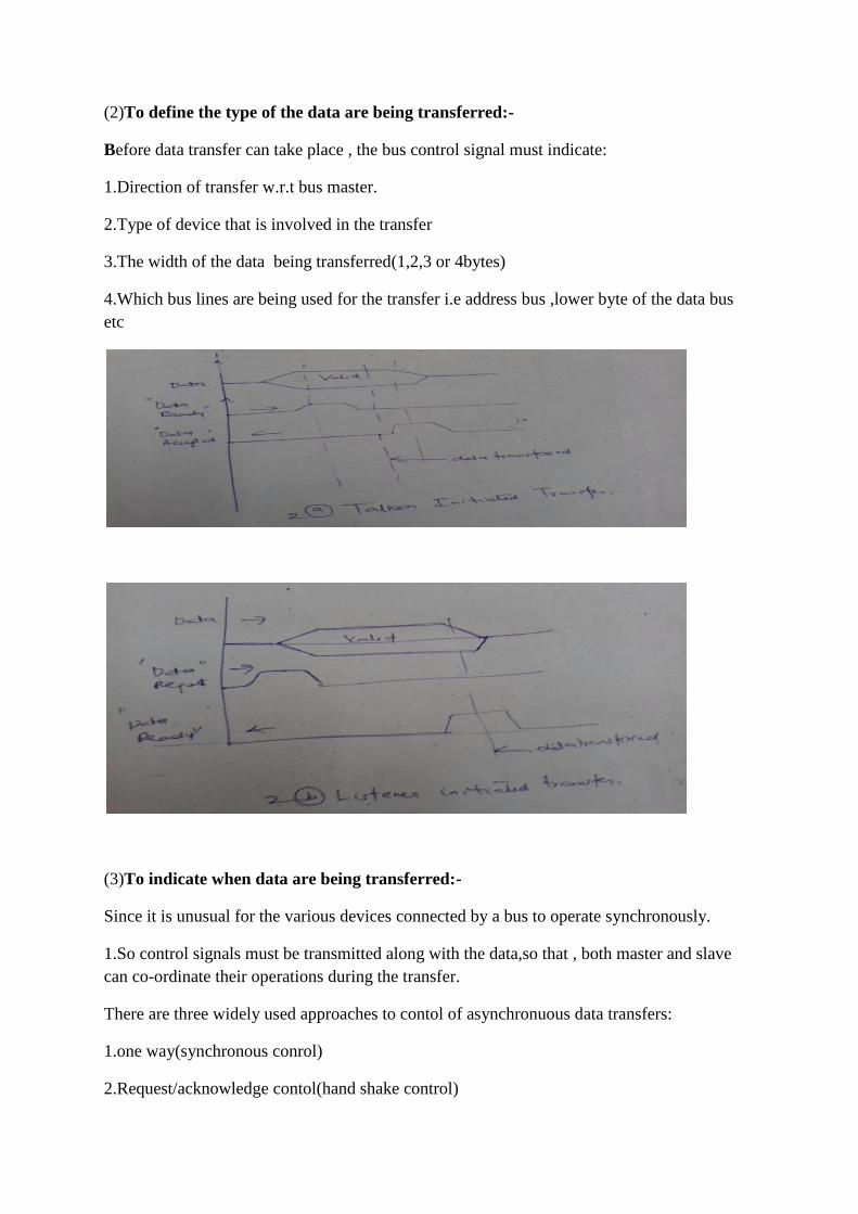
(2)To define the type of the data are being transferred:-
Before data transfer can take place , the bus control signal must indicate:
1.Direction of transfer w.r.t bus master.
2.Type of device that is involved in the transfer
3.The width of the data being transferred(1,2,3 or 4bytes)
4.Which bus lines are being used for the transfer i.e address bus ,lower byte of the data bus
etc
(3)To indicate when data are being transferred:-
Since it is unusual for the various devices connected by a bus to operate synchronously.
1.So control signals must be transmitted along with the data,so that , both master and slave
can co-ordinate their operations during the transfer.
There are three widely used approaches to contol of asynchronuous data transfers:
1.one way(synchronous conrol)
2.Request/acknowledge contol(hand shake control)
3.Semi synchronous control
4.Multi functional data transfer control
1.ONE –WAY (SYNCHRONOUS CONTROL):-
1.A single Data ready is sent out by the master after it has placed data on the data bus(if it is a
talker) (or)
2.Reading the data bus (if it is listner), the signal is called Data request.
3.The slave must respond to the active transition of the control signal with in a prescribed
time interval otherwise data will not be transferred properly.
4. Time intervals t1& t2 are highly dependent on implementation details like device operating
speed , bus propagation delay etc
Advantages with this approach:-
1. simplicity.
2. speed of communication.(i.e it has single bus propagation delay).
Disadvantages:-
1.This scheme is sensitive to transmission speed.
communicating devices that have very different operating speed is difficult & will lead to
inefficient use of the bus bandwidth.
(2)Request/acknowledge (handshake) control:-
Here two control are used.
1.Data Request:When it has successfully read the data if it is a listner.
2.Data Ready:when it has placed the data on the data bus if it is a talker.
Advantages:
1.Reduces the noise sensitivity.
2.Any speed is possible.
Disadvantages:
1.Each data transfer involves two bus propagation delays.
3.a.Explain about the various bus topologies.List the advantages and disadvantages.
figures -3m
+advantages+disadvantages-3m
BUS TOPOLOGY:
There are many ways of interconnecting devices so that information can be
transformed between them. The most suitable method of interconnection will depend on the
type of information to be transmitted how frequently transmission occurs, the way in which
the bus lines are shorted, and the urgency of communication.
The microcomputer can have one of the three basic topologies
1. Star Architecture
2. Daisy Chain Architecture
3. Party line Architecture
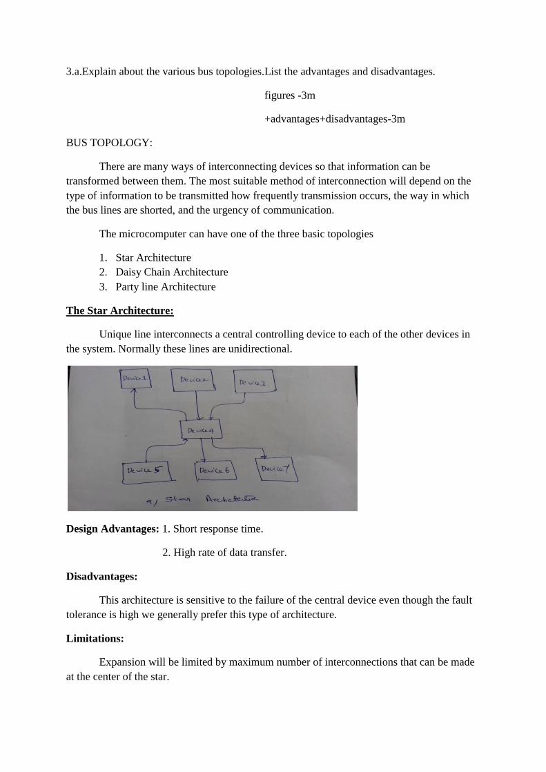
The Star Architecture:
Unique line interconnects a central controlling device to each of the other devices in
the system. Normally these lines are unidirectional.
Design Advantages: 1. Short response time.
2. High rate of data transfer.
Disadvantages:
This architecture is sensitive to the failure of the central device even though the fault
tolerance is high we generally prefer this type of architecture.
Limitations:
Expansion will be limited by maximum number of interconnections that can be made
at the center of the star.
Usage:
This is used only where rapid simultaneous transfer of information must occur
between a number of devices and one special device in the microcomputer system.
Example 1:- Power fail lines to the centralized power fail logic circuit in the distributed
system.
Example 2:- Interrupt request lines to a centralized Interrupt controller in a master that is
receiving several slaves.
The Daisy chain Architecture:
Unidirectional bus lines interconnect the devices to form a ring or loop. Devices read
in & re-transmit information along the dairy chain until the data reach the correct destination
device.
Disadvantages: 1. Data transfer is slow.
Reason: Due to the retransmission between the devices and device having the
propagation delay.
2. A fault on any one of the bus lines that for the ring will be seversely disrupt
operations, but some part of communication is possible.
Advantages: However, the no. of interconnections on any device is small and
interconnection logic is also simple.
Limitations: Expansion will be limited only by maximum loop delay which can be tolerated.
Usage: This topology is used where the positions of the devices around the loop has
significance or where the no. of devices interconnections must be kept minimum.
Example 1 & 2:-
The interrupt acknowledge lines of an interrupt controller or bus grant lines of a bus
controller.
Party line Architecture:
Information is sent out along a single set of bidirectional bus lines that interconnect
every device in the system.
Usage: 1. Point to point transmission: Only the destination device accepts the data.
2. Broadcaste transmission: All devices accept the data.
The party line Architecture requires relatively few interconnections.
Exact Usage: This is almost always used for high speed transmission of short blocks of the
data over short distances.
This is mostly used in single master microcomputer system at high data speed.
Disadvantages: Bus interconnection logic will be complex i.e., heavily multiplexed.
Limitations: Expansion of this architecture is limited only by the additional electrical
loading imposed on the bus.
Example 1:- Bus address and data lines scheme.
There are two types of party lines bus given below
1. Exclusive party line bus.
2. Public party line bus.
Exclusive Party line Bus:
This kind of scheme allows the bus is driven in one direction by one device at one
time.
Usage:
Exclusive Party line Bus: All the devices are connected with three state bus drivers
so one of the devices may be disconnected while the bus is being used.Public Party line
Bus: This is bi-directional & may be driven by several devices at the same time.
Usage:
Public Party line Bus: They are driven by via open collector bus driven so that the
transmitted information is the wired-OR (Active low logic signals)
OR
Wired- AND (Active high signals) of the outputs of the devices driving the bus.
3.b.Explain the features of ISA and VME Bus standards. 3+3
ISA bus architecture
ISA bus architecture is the basis of personal computer. 8-bit ISA bus is used in single user
systems with 80386 and 80486 processors. There are 24 address lines and '16 data lines in it.
It operates at 8 MHz and 2 to 8 clock cycles are needed to transfer data. The data transfer rate
of the system is less when 8-bit ISA bus is used with 32 bit processor having 32 bit address
and data bus. So, 16 bit ISA bus is used to transfer data. Many peripherals such as disk
controller, printer, and scanner can be connected to ISA bus.
VME BUS:
The architectural concepts of the VME bus are based on VERSA bus. In order to demonstrate
the concept, three prototype boards namely: (1) 68000 CPU board (2) Dynamic memory
board & (3) A static memory board are introduced. These are named the new bus. VERSA
bus, later renamed as VME bus (VERSA MODULE EUROPEON bus).
It is a flat 32 bit memory model and free of memory segmentation. VME uses
seperate 32 bit data and address buses. but actually 24 bit address bus & 16 bit data bus are
implemented for user applications.
The bus is controlled by a set of nine lines, known as arbitration bus. All
communications are controlled by the card in slot one of the Eurocard chassis, known as the
arbiter module. Two arbitration modes are supported -- Round Robin and prioritized.
A card can attempt to become the bus master by holding one of the four bus
request lines low. With Round robin arbitration, the arbiter cycles amongest bus request lines
BR0-BR3 to determine which of the potentially simultaneous requesters will be granted the
bus.With priority arbitration, BR0-BR3 use a friend priority scheme (BR0 lowest, upto BR3
highest) and the arbiter will grant the bus to the highest priority requestor.
When the arbiter has determined which of the bus requests to grant, it asserts
the corresponding Bus grant line (BG0-BG4) for the level that won bus master ship. If two
masters simultaneously request the bus using the same BR line, then the arbiter grants the bus
to the module which is closer to the arbiter. The master granted the bus will then indicate that
the bus is in use by asserting BUS BUSY(BBSY). The following VME bus system represents
the operation of VME bus.
4.a.what are the faults in Add-on cards we should catch by a careful visual inspection
?Explain
Always physically inspect the circuit card. Note the revision level, switch settings, and
anything out of the ordinary that could be a clue to the problem.
The following is a checklist of items a technician should look for:
1. Take note of the board ID and revision level. This is of particular importance when
comparing two boards. Be sure we are not hunting revision changes instead of faults. .
2. Visually check for indications of rough handling; scratches, buckling, cracks, etc. When a
scratch is found across a trace, always check for continuity with wer Tracker in LOW range
even if it looks okay.
3. Intermittent faults can be caused by fractures. Hold the board up to a bright light and look
for cracks. Check for trace continuity while gently flexing the board if cracks are found
anywhere on the card.
4. Take note if the board is multilayered. The more layers a board has the more difficult it
will be to trace foils and component interconnections.
5. Inspect the soldering on the board. Look for poor quality, shorts, opens, cold solder joints,
and fractures around hot components
. 6. Closely inspect previous repairs. Verify that the proper components were used and were
installed in their proper positions. Check for continuity from traces to pads with wer tracker
in LOW range. Look for tiny cracks in pads and traces, they can be intermittent. Verify
continuity through eyelets.
7. Inspect the board for damaged foil runs that may be pulled up, burnt or discolored.
8. Inspect mod wiring, the leads can break loose at the solder points.
9. Be aware that unclipped component leads may bend over and cause short circuits.
10. Visually inspect the component side of the board for broken or missing components.
Large or precariously mounted parts should be given special attention.
11. Check all plug-in components for legs that may be bent or folded under.
12. Check for blown fuses and heat stressed components. Don't forget wer nose- some
components may appear in good condition while internally heat damaged. Sniff for the tell-
tale "burnt electronics" odor.
13. Look for swollen or leaky electrolytic capacitors.
14. Take note of switch settings, option blocks, eprom revision levels, and strapping. This is
very important when doing good/bad board comparisons with a Tracker.
15. Inspect any previously cut component legs or traces for proper reconnection.
16. Resistors are easily fractured by mechanical shock. Gently push suspected resistors to
verify their condition. It is important to verify the fault, if possible.
No one wants to waste time looking for nonexistent or incorrectly diagnosed problems.
Operate the board in the same environmental conditions, if possible. Think before we leap. If
a stereo has a noisy left channel, we shouldn't start by troubleshooting the right channel or the
power supply. We would look in the left channel circuitry for a possible intermittent. Test
and verify after each repair procedure. After the inspection, there may be some repair
required. Test the operation of the board after the work is completed. When tested, if the
symptoms change for the worse, go back and check the work we have done before going on
to look for the original problem.
4.b.What is an ADD-ON CARD ?Explain any one of add-on card with neat diagram?
2+4
An add-on is either a hardware unit that can be added to a computer to increase its
capabilities or a program utility that enhances a primary program . Examples of add-ons for a
computer include card s for sound, graphics acceleration, modem capability, and memory.
Software add-ons are common for games, word processors, and accounting programs.
Types of expansion cards in a computer
• Interface card (ATA, Bluetooth, EIDE, Firewire, IDE, Parallel, RAID, SCSI, Serial,
and USB)
• Modem
• MPEG Decoder
• Network Card
• Sound Card
• Video capture card
• Video Card
Sound Card
Alternatively referred to as an audio output device, sound board, or audio card. A sound
card is an expansion card or IC for producing sound on a computer that can be heard
through speakers or headphones. Although the computer does not need a sound device to
function, they are included on every machine in one form or another, either in an expansion
slot (sound card) or on the motherboard (onboard).
Sound card connections
The picture is an example of a sound card audio ports or audio jacks on the back of wer
computer, associated colors, and the connector symbols.
• Digital Out (White or Yellow; words: "Digital" or "Digital Out") - Used with surround sound
or loudspeakers.
• Sound in or line in (Blue; Arrow pointing into waves) - Connection for external audio
sources, e.g. tape recorder, record player, or CD player.
• Microphone or Mic (Pink; Microphone) - The connection for a microphone or headphones.
• Sound out or line out (Green; Arrow pointing out of waves) - The primary sound connection
for wer speakers or headphones. This sound card also has a second (black) and third (orange)
sound out connector.
• Firewire (Not pictured) - Used with some high-quality sound cards for digital video cameras
and other devices.
• MIDI or joystick (15 pin yellow connector) - Used with earlier sound cards to connect MIDI
keyboard or joystick.
Usually the cables connecting to the devices are also color-coded and will match or be close
to the colors the cables connect into. For example, the end of the speakers cable may have a
green line or be completely green.
5a.Explain briefly the need of different types of device drivers? 6M
A: In computing, a device driver (commonly referred to simply as a driver) is a computer
program that operates or controls a particular type of device that is attached to a computer. A
driver provides a software interface to hardware devices, enabling operating systems and
other computer programs to access hardware functions without needing to know precise
details of the hardware being used.
A driver communicates with the device through the computer bus or communications
subsystem to which the hardware connects. When a calling program invokes a routine in the
driver, the driver issues commands to the device. Once the device sends data back to the
driver, the driver may invoke routines in the original calling program. Drivers are hardware
dependent and operating-system-specific. They usually provide the interrupt handling
required for any necessary asynchronous time-dependent hardware interface.
Common levels of abstraction for device drivers include:
• For hardware:
• Interfacing directly
• Writing to or reading from a device control register
• Using some higher-level interface (e.g. Video BIOS)
• Using another lower-level device driver (e.g. file system drivers using disk drivers)
• Simulating work with hardware, while doing something entirely different
• For software:
• Allowing the operating system direct access to hardware resources
• Implementing only primitives
• Implementing an interface for non-driver software (e.g., TWAIN)
• Implementing a language, sometimes quite high-level (e.g., PostScript)
So choosing and installing the correct device drivers for given hardware is often a key
component of computer system configuration.
5.b.What is the difference between static and loadable device drivers? 6M
SLNO
STATIC DEVICE
DRIVERS
LOADBLE
DEVICE DRIVERS
1 The static device driver has a
plurality of handlers or
functions , used to control a
device
The loadable device drivers are
loaded dynamically.
2 The control status register
(CSR) determines the existence
of static device drivers.
The bus configuration code
determines the existence of
loadable device drivers before
calling.
3 It is not possible to install static
device drivers from other
vendors
It is easy for administrators to
install loadable device drivers
from other vendors.
4 These device drivers do not
allow device drivers and other
modules to be configured into
kernel while the system is
running.
These improve system availability
by allowing device drivers and
other modules to be configured
into kernel , while the system is
running.
5 Conservation of system
resources in these device
drivers is not possible when not
in use.
Conservation of system resources
in loadable device drivers can be
done by unloading them
frequently when not in use.
6 Static device drivers do not
allow administrators to load
and unload modules according
to demand.
Loadable device drivers allow
administrators to load and unload
modules according to demand.
7 Auto loading of reqd. modules
encountered by the kernel is not
possible.
Auto loading occurs when the
kernel detects a particular
loadable module reqd. to
accomplish some task.
8 Efficient use of kernel memory
is not possible.
This efficiently saves kernel
memory. [ adv of loadable
device drivers is that they can be
loaded only when necessary &
then unloaded]
6.a.Write in detail about data flow techniques 6M
DATA FLOW PROGRAM
LabVIEW follows a dataflow model for running VIs. A block diagram node executes when
all its inputs are available. When a node completes execution, it supplies data to its output
terminals and passes the output data to the next node in the dataflow path.
Visual Basic, C++, JAVA, and most other text-based programming languages follow a
control flow model of program execution. In control flow, the sequential order of program
elements determines the execution order of a program. For a data flow programming,
consider a block diagram shown in Figure 2.14 that adds two numbers and then subtracts
50.00 from the result of the addition. In this case, the block diagram executes from left to
right, not because the objects are placed in that order, but because the Subtract function
cannot execute until the Add function finishes executing and passes the data to the Subtract
function. A node executes only when data are available at all of its input terminals, and it
supplies data to its output terminals only when it finishes execution.
Figure 6.a Data flow program.
6.b..Compare conventional programming and graphical programming.Give the merits of
graphical programming. 4+2M
Merits of graphical programming:
1.Graphical programming is a visually-oriented approach to programming. Graphical
programming is easier and more intuitive to use than traditional textual programming.
2. Graphical environments are better for nonprogrammers and useful for developing
virtual instruments quickly and need to be reconfigured rapidly.
7.a.Explain the three main components if a virtual instrument (VI). FIG-2M+4M
This three-step approach has been one of the pillars of virtual instrumentation model as
shown in Figure 7.a
Fig 7.a
7.b.Write about HMI and SCADA. fig:2+4M
SCADA is an acronym that stands for Supervisory Control and Data Acquisition. SCADA
refers to a system that collects data from various sensors at a factory, plant or in other remote
locations and then sends this data to a central computer which then manages and controls the
data.
SCADA systems are used not only in industrial processes: e.g. steel making, power
generation (conventional and nuclear) and distribution, chemistry, but also in some
experimental facilities such as nuclear fusion. The size of such plants range from a few 1000
to several 10 thousands input/output (I/O) channels.
A SCADA system usually includes signal hardware (input and output), controllers,
networks, user interface (HMI), communications equipment and software. All together, the
term SCADA refers to the entire central system. The central system usually monitors data
from various sensors that are either in close proximity or off site (sometimes miles away).
8.a.Write about i.VI chassis. ii.Common Instrument Interfaces. 1+5M
The most common categories of instrument interfaces are GPIB, serial, modular instruments
and PXI modular instruments. Additional types of instruments include image acquisition,
motion control, USB, Ethernet, parallel port, NI-CAN and other devices.
Fig 8.a i.Interfaces
Fig 8.a ii.GPIB Interface
When we use PCs to control instruments, we need to understand properties of the instrument,
such as the communication protocols to use. We must consider the following issues with PC
control of instrumentation:
● Type of connector (pinouts) on the instrument
● Cables needed—null-modem, number of pins, male/female
● Electrical properties involved—signal levels, grounding, cable length restrictions
● Communication protocols used—ASCII commands, binary commands, data format
● Software drivers available
GPIB COMMUNICATION
The ANSI/IEEE Standard 488.1-1987, also known as General Purpose Interface Bus (GPIB),
describes a standard interface for communication between instruments and controllers from
various vendors. GPIB, instruments offer test and manufacturing engineers the widest
selection of vendors and instruments for general-purpose to specialized vertical market test
applications as shown in Figure 10.3 GPIB instruments are often used as stand-alone
benchtop instruments where measurements are taken by hand. We can automate these
measurements by using a PC to control
the GPIB instruments.
IEEE 488.1 contains information about electrical, mechanical and functional specifications.
The ANSI/IEEE Standard 488.2-1992 extends IEEE 488.1 by defining a bus communication
protocol, a common set of data codes and formats, and a generic set of common device
commands.
GPIB is a digital, 8-bit parallel communication interface with data transfer rates of 1 Mbyte/s
and higher, using a three-wire handshake. The bus supports one system controller, usually a
computer, and up to 14 additional instruments. The GPIB protocol categorizes devices as
controllers, talkers, or listeners to determine which device has active control of the bus. Each
device has a unique GPIB primary address between 0 and 30. The controller defines the
communication links, responds to devices that request service, sends GPIB commands, and
passes/receives control of the bus. Controllers instruct talkers to talk and to place data on the
GPIB. We can address only one device at a time to talk. The controller addresses the listener
to listen and to read data from the GPIB. We can address several devices to listen.
SERIAL PORT COMMUNICATIONS
Serial communication is a popular means of transmitting data between a computer and a
peripheral device such as a programmable instrument or even another computer. Serial
communication uses a transmitter to send data, one bit at a time, over a single
communication line to a receiver. We can use this method when data transfer rates are low or
we must transfer data over long distances.
Serial communication is popular because most computers have one or more serial ports, so no
extra hardware is needed other than a cable to connect wer instrument to the computer (or
two computers together) as shown in Figure 8.a
Fig 8.a
8.b.Explain in brief about loops and charts and explain them with suitable examples.2+2+2M
FOR LOOPS
A For Loop executes a subdiagram, a set number of times. Figure 4.1(a) shows a For Loop in
LabVIEW and Figure 4.1(b) shows the flow chart equivalent of the For Loop functionality
subdiagram. Set the count explicitly by wiring a value from outside the loop to the left or top
side of the count terminal, or set the count implicitly with auto-indexing. Auto-indexing is
explained in chapter 5. A VI will not run if it contains a For Loop that does not have a
numeric value wired to the count terminal.
The iteration terminal ‘i’ (an output terminal) contains the number of completed iterations.
The iteration count always starts at zero. During the first iteration, the iteration terminal
returns 0. Figure 4.2 shows a simple For Loop which generates 10 random numbers and
displays in the Random Number Indicator.
WHILE LOOPS
A While Loop executes a subdiagram until a condition is met. The While Loop is similar to a
Do Loop or a Repeat-Until Loop in text-based programming languages. Figure 4.4(a) shows
a While Loop in LabVIEW and 4.4(b) is the flow chart equivalent of the While Loop. The
While Loop always executes at least once. The For Loop differs from the While Loop in that
the For Loop executes a set number of times. A While Loop stops executing the subdiagram,
only if the expected value at the conditional terminal exists.
if true
WAVEFORM CHARTS
The waveform chart is a special type of numeric indicator that displays one or more plots of
data typically acquired at a constant rate.
Waveform charts can display single or multiple plots. Figure 7.3 shows the elements of a
multiplot waveform chart. Two plots are displayed: Raw Data and Running Avg. The
waveform chart maintains a history of data or buffer from previous updates.
9.a.Discuss the PC based control 3+3M
ii.VXI based control
A: PC based control:
The computer (an ordinary PC or PC-compatible) controls each item of external
instrumentation and automates the test and calibration procedure, increasing
throughput, consistency, and reliability, freeing the test engineer for higher
level tasks. A PC-based arrangement thus provides a flexible and highly cost effective
alternative to traditional methods. Furthermore, systems can be easily
configured to cope with the changing requirements of the user.
In general, PC-based instrumentation and control systems offer the following
advantages:
• Flexible and adaptable: the system can be easily extended or reconfigured
for a different application.
• The technology of the PC is well known and understood, and most companies
already have such equipment installed in a variety of locations.
• Low-cost PC-based systems can be put together at a faction of the cost
associated with dedicated controllers.
• Rugged embedded PC controllers are available for use in more demanding
applications. Such systems can be configured for a wide range of instrumentation
and control applications with the added advantage that they use the
same familiar operating system environment and programming software that
runs on a conventional PC.
• Availability of an extensive range of PC-compatible expansion cards from
an increasingly wide range of suppliers.
• Ability to interface with standard bus systems (including the immensely
popular IEEE-488 General Purpose Instrument Bus).
ii.VXI is used in many different applications ranging from test and measurement and ATE, to
data acquisition and analysis in both research and industrial automation. Although some VXI
systems today are purely VXI, many users are migrating to VXI by integrating it into existing
systems consisting of GPIB instruments, VME cards, or plug-in data acquisition (DAQ)
boards. We can control a VXI system with a remote general-purpose computer using the
high-speed Multisystem eXtension Interface (MXI) bus interface or GPIB. We can also
embed a computer into a VXI chassis and control the system directly. Whatever wer system
configuration needs may be, VXI offers the flexibility and performance to take on today’s
most challenging applications.
VXIbus Mechanical Configuration
Physically, a VXIbus system consists of a mainframe chassis that has the physical mounting
and backplane connections for plug-in modules, as shown in Figure 9A.. The VXIbus uses
the industry-standard IEEE-1014 VMEbus as a base architecture to build upon. As shown in
Figure 2, VXI uses the full 32-bit VME architecture, but adds two board sizes and one
connector. The P1 connector and the center row of the P2 connector are retained exactly as
defined by the VME specification. The VME user-definable pins on the P2 connector and the
additional pins on P3, the third VXI connector, implement instrumentation signals between
plug-in modules directly on the backplane.
FIG 9a VXI BUS SYSTEM
9.b.What is VISA?How it is developed and explain its hardware protocol. 2+4M
VISA
Virtual Instrument Software Architecture (VISA) is the lower layer of functions in the
LabVIEW instrument driver VIs that communicates with the driver software. VISA by itself
does not provide instrumentation programming capability. VISA is a high-level API that calls
low-level drivers. As shown in Figure 10.9 VISA can control VXI, GPIB, serial, or
computer-based instruments and makes the appropriate driver calls depending on the type of
instrument used. When debugging VISA problems, remember that an apparent VISA
problem could be an installation problem with one of the drivers that VISA calls.
Fig 9.b VIRTUAL INSTRUMENT SOFTWARE ARCHITECTURE
VISA or Virtual Instrument Software Architecture is a protocol built upon 488.2 driver and
functions to meet the industry needs for having a way to easily interface with multiple I/Os
and have all manufacturers of instruments and instrument drivers follow a protocol. VISA
created by the VXIplug&play Alliance which is composed of the top 35 instrument
manufacturers such as HP. National Instruments is a leading member of the alliance. The
resource name contains information on the type of I/O interface and the device address. We
can use an alias we assign in MAX instead of the instrument descriptor. (Mac OS) Edit the
visaconf.ini file to assign a VISA alias. (UNIX) Use the visaconf utility. If we choose not to
use the Instrument I/O Assistant to automatically generate code for we, we can still write a VI
to communicate with the instrument.