General information about City & Guilds may be obtained from Customer Relations at the above address or on +44 (0)20 7294 2787 or by [email protected].
Equal opportunities
City & Guilds fully supports the principle of equal opportunities and we are committed to satisfying this principle in all our activities and published material.
Every effort has been made to ensure that the information contained in this publication is true and correct at the time of going to press. However, City & Guilds’ products and services are subject to continuous development and improvement and the right is reserved to change products and services from time to time. City & Guilds cannot accept liability for loss or damage arising from the use of information in this publication.
Following the accreditation of the Technician IVQs in Engineering(2565) on the National Qualifications Framework of England,Wales and Northern Ireland (NQF), some changes have beenmade to the qualification, at the request of the Office of theQualifications and Examinations Regulator (Ofqual), thequalifications regulator in England.
These changes took effect on 1 June 2009 and are outlined on pages 5–6.
Note: the content of the qualifications has not changed following accreditation.
Changes to the qualification titles
The qualification titles have changed as follows:
Advanced Technician Diploma in Engineering – AppliedMechanical Engineering (Manufacturing) (2565-03)changed to Level 5 IVQ Advanced Technician Diploma in Engineering
Following the accreditation of the Technician IVQs in Engineering,each unit has been given an accreditation reference numberwhich will appear on the Certificate of Unit Credit.
The content of the units is unchanged.
Level 5 IVQ Advanced Technician Diploma in Engineering
Registration process for the theory examination has not changed.
Result submission for practical assessment
Result submission process for the practical assessments has not changed.
Change to the grading
The grade ‘Credit’ has been changed to ‘Merit’. All other grades areunchanged. The content of the units concerned is also unchanged.
Notification of Candidate Results (NCR) and Certificate
of Unit Credit (CUC)
Notification of Candidate Results (NCR) and Certificate of UnitCredit (CUCs) continue to be available on completion of eachassessment (theory or practical).
Final certificate will be issued on successful completion of all the required assessments.
‘Theory only’ routes
The ‘Theory only’ routes continue to be available as unaccredited qualifications.
Changes to the certificate layout
Certificates issued on completion of an accredited IVQ show theaccredited title and the accreditation number for the qualification.The level in the accredited title refers to the NQF level thequalification is accredited at.
The certificate also lists all the units achieved, including the gradeand the unit accreditation number.
The certificate carries the logos of the regulatory authorities in England, Wales and Northern Ireland indicating that the NQF accreditation only applies to these countries.
IVQ in Engineering 256506
Regulations: 1998 edition 07
Levels of City & Guilds qualifications
All City & Guilds qualifications are part of an integrated progressivestructure of awards arranged over eight levels, allowing people to progress from foundation to the highest level of professionalcompetence. Senior awards, at levels 4 to 7, recognise outstandingachievement in industry, commerce and the public services. Theyoffer a progressive vocational, rather than academic, route toprofessional qualifications. An indication of the different levels and their significance is given below.
NQF level# City & Guilds qualifications/programmes Other qualifications*
# National Qualifications Framework of England, Wales and Northern Ireland (NQF)* Broad comparability in level** Only graduates of the City & Guilds College, Imperial College of Science, Technology and Medicine, are awarded
the Associateship (ACGI)*** Part of a new qualification structure which is being introduced across the IVQ provisionIVQ International Vocational QualificationsNVQ National Vocational Qualifications
[ This page is intentionally blank ]
About City & Guilds
We provide assessment and certification services for schools and colleges, business and industry, trade associations andgovernment agencies in more than 100 countries. We have over120 years of experience in identifying training needs, developingassessment materials, carrying out assessments and trainingassessment staff. We award certificates to people who haveshown they have mastered skills that are based on world-classstandards set by industry. City & Guilds International provides a particular service to customers around the world who needhigh-quality assessments and certification.
Introduction to this programme
We have designed the Advanced Technician Diplomas inMechanical Engineering programme for those undergoingtraining or employed in this area of work. The programme aims to reflect the international nature of the knowledge and skills and activities needed for different countries or cultures.
We provide certificates for all work-related areas at seven levels within our structure of awards shown in Appendix B. This programme covers level 4. The standards and assessmentsfor the Certificate (level 2) and the Diploma (level 3) are published separately.
Certificate
The certificate (about 300-450 guided learning hours) provides a broad introduction to the theory and practical sides of engineering for a front line worker or a person beginning anacademic training programme.
Diploma
The diploma (about 600 guided learning hours) provides more practice involving a broader range of skills appropriate to a person who may also supervise, or who is going on intohigher education.
Advanced Diploma
The advanced diploma (about 600 guided learning hours) takesthese skills to the level appropriate for a person preparing for orworking in first-level management. It is also appropriate forsomeone who wants to receive specialised training at a high level.
We stress that these figures are only a guideline and that we award certificates and diplomas for gaining and showing skills by whatever mode of study, and not for periods of timespent in study.
Full Technological Diploma
We will award the Full Technological Diploma (FTD) in Engineeringto someone who is at least 21, who has had at least two yearsrelevant industrial experience, and who has successfully finishedthe assessments for the diploma and advanced diploma levels ofthis award. If candidates enter for this diploma, they must alsosend us a portfolio of evidence to support their application.
Making entries for assessments
Candidates can only be entered for the assessments in this subject if the approved examination centres agree.Candidates must enter through an examination centre we have approved to carry out the assessments for 2565 TechnicianAwards in Engineering.
There are two ways of entering candidates for assessments.
Internal candidates
Candidates can enter for examinations if they are taking or havealready finished a course at a school, college or similar traininginstitution that has directed their preparation whether by going to a training centre, working with another institution, or by openlearning methods.
External candidates
These are candidates who have not finished a programme asdescribed above. The examination centres must receive theirapplication for entry well before the date of the examinationconcerned. This allows them to act on any advice you give aboutassessment arrangements or any further preparation needed.External candidates carrying out practical assignments andprojects will need extra time and guidance to make sure that theymeet all the requirements for this part of the assessment.
In this publication we use the term ‘centre’ to mean a school,college, place of work or other institution.
Resources
If you want to use this programme as the basis for a course, youmust read this booklet and make sure that you have the staff andequipment to carry out all parts of the programme. If there are nofacilities for realistic practical work, we strongly recommend thatyou develop links with local industry to provide opportunities forhands-on experience.
IVQ in Engineering 2565
Regulations: 1998 edition 09
Assessments
Summary
There is one level of this award.
Advanced diplomas
We use a numbering system to allow entries to be made for ourawards. The numbers used for this programme are as follows.
We use award numbers to describe the subject and level of theaward.
Award number
2565-03 Advanced Technician Diploma in Applied MechanicalEngineering – Manufacturing
Advanced Technician Diploma in MechanicalEngineering Theory – Manufacturing
Advanced Technician Diploma in Applied MechanicalEngineering – Plant Technology
Advanced Technician Diploma in MechanicalEngineering Theory – Plant Technology
We use component numbers to show units for which we mayaward a certificate of unit credit.
Component numbers
026 Mechanical Principles030 Engineering Project033 Materials and Processes034 Advanced Manufacturing and Management035 Advanced Manufacturing Engineering Practical
Assignments038 Plant Technology and Maintenance Procedures039 Advanced Plant Practical Assignments040 Plant Hydraulics and Pneumatics041 Plant Hydraulics and Pneumatics Practical Assignments047 Advanced Mathematics
This unit is an option recommended for candidatesentering Higher Education
048 Computer Aided Draughting 2
We use these numbers throughout this booklet. You must usethese numbers correctly if you send forms to us.
Assessments required for specific awards
Advanced Technician Diploma in Applied
Mechanical Engineering – Manufacturing
To carry out what is needed for the Advanced Technician Diplomain Applied Mechanical Engineering – Manufacturing, candidatesmust be successful in all of the following assessments.
2565-03-026 Mechanical Principles (written paper which lastsone and a half hours)
The practical assignments are carried out during the learningprogramme and should be finished by the date of the writtenexamination so you can send all the results to us. (See appendix A).
To receive this award candidates must complete the followingpractical assignments.030/1, 035/1, 035/2, 048/1, 048/2, 048/3 and 048/4.
(Total seven practical assignments)
Advanced Technician Diploma in Mechanical
Engineering Theory – Manufacturing
To carry out what is needed for the Advanced Technician Diplomain Mechanical Engineering Theory – Manufacturing, candidatesmust be successful in all of the following assessments.
2565-03-026 Mechanical Principles (written paper which lastsone and a half hours)
2565-03-033 Materials and Processes (written paper whichlasts two hours)
2565-03-034 Advanced Manufacturing and Management(written paper which lasts three hours)
(Total three written papers)
There are no practical assignments for this award.
IVQ in Engineering 256510
Advanced Technician Diploma in Applied
Mechanical Engineering – Plant Technology
To carry out what is needed for the Advanced Technician Diplomain Applied Mechanical Engineering – Plant Technology,candidates must be successful in all of the following assessments.
2565-03-026 Mechanical Principles (written paper which lastsone and a half hours)
The practical assignments are carried out during the learningprogramme and should be finished by the date of the writtenexamination so you can send all the results to us. (See appendix A).
To receive this award candidates must complete the followingpractical assignments.030/1, 039/1, 039/2, 041/1, 041/2, 048/1, 048/2, 048/3 and 048/4.
(Total nine practical assignments)
Advanced Technician Diploma in Mechanical
Engineering Theory – Plant Technology
To carry out what is needed for the Advanced Technician Diplomain Mechanical Engineering Theory – Plant Technology, candidatesmust be successful in all of the following assessments.
2565-03-026 Mechanical Principles (written paper which lastsone and a half hours)
2565-03-038 Plant Technology and Maintenance Procedures(written paper which lasts three hours)
2565-03-040 Plant Hydraulics and Pneumatics (written paperwhich lasts three hours)
(Total three written papers)
There are no practical assignments for this award.
Fixed and free date assessments
We provide assessments in two ways:
a Fixed date
These are assessments which are carried out on dates and times we set. These assessments have no brackets around their numbers.
b Free date
These are assessments which are carried out at a college or other training establishment on a date or over a period whichthe college chooses. These assessments have brackets around their numbers.
In this programme the written assessments are fixed date. Thepractical assignments are free date.
You must carry out assessments according to our International Directory of Examinations and Assessments. If there are any differences between information in thispublication and the current directory, the Directory has the most up-to-date information.
Results and certification
Everyone who enters for our certificates, diplomas and advanceddiplomas receives a ‘Notification of Candidate Results’ givingdetails of how they performed.
If candidates successfully finish any assessment within thisprogramme (for example, any one of the examination papers)they will receive a certificate of unit credit towards the certificateor diploma for which they are aiming. We grade courseworkassessments (practical assignments) as pass or fail. We gradewritten assessments on the basis of fail, pass, credit ordistinction. The certificate of unit credit will not mentionassessments which they do not enter, which they failed or fromwhich they were absent.
Each certificate or diploma clearly states what candidates need forfull certification at the relevant level, allowing schools, colleges andemployers to see whether they have met the full requirements.
If candidates successfully finish all the requirements for a fullcertificate or a diploma, they will automatically receive theappropriate certificate.
We will send the ‘Notification of Candidate Results’, certificates ofunit credit, certificates, diplomas and advanced diplomas to theexamination centre to be awarded to successful candidates. It isyour responsibility to give the candidates the certificates. Ifcandidates have a question about the results and certificates,they must contact you. You may then contact us if necessary.
We will also send you a results list showing how all candidates performed.
Regulations: 1998 edition 11
How to offer this programme
To offer this programme you must get approval from us. There aretwo categories of approval.
Subject approval
We give approval to offer a teaching course based on this syllabus.
Examination centre approval
We give approval to enter candidates for examinations.
To be approved by us to offer a teaching course you must send usthe application form.
To enter candidates for examinations you must be approved by usas an examination centre. For this programme it is possible to actas a registered examination centre only, and accept externalcandidates. Approved examination centres must provide suitablefacilities for taking examinations, secure places to keep theexamination papers and materials, and may have an appointedvisiting verifier to review practical work.
After we have received and accepted an application, we will sendan approval letter confirming this. You can then send entries in atany time using the International Directory of Examinations andAssessments for guidance.
Please note that in this section we have provided an
overview of centre approval procedures. Please refer to
the current issue of ‘Delivering International Qualifications
– Centre Guide’ for full details of each aspect of these
procedures.
Other informationDesigning courses of studyCandidates for the various awards in engineering will have comefrom different backgrounds and will have different employmentand training experiences. We recommend the following:
• carry out an assessment of the candidates’ achievements soyou can see what learning they already have and decide thelevel of entry they will need; and
• consider what learning methods and places will best suit them.
When you assess a candidate’s needs, you should designteaching programmes that consider:
• what, if any, previous education qualifications or training thecandidate has, especially in the various general vocationaleducation certificates we provide; and
• what, if any, previous practical experience the candidate haswhich is relevant to the aims of the programme and from whichthey may have learned the relevant skills and knowledge.
When you choose learning methods and places, you shouldconsider the results of your assessments and whether thefollowing are available.
• Open or distance learning material.• Workplace learning that can be carried out on site or between
you and a local workplace. This will allow the candidates accessto specialised equipment and work experience.
• Working with other registered centres to share facilities.• Opportunities for co-operative learning between candidates for
different certificates who need to gain similar skills.
As long as the candidates meet the aims of this learningprogramme the structures of courses of study are up to you. So, itis possible to include extra topics that meet local needs.
You should avoid teaching theory alone. As far as possible thepractical work should be closely related to work in the classroomso that candidates use their theory in a realistic workenvironment. You can use formal lectures in the classroom withappropriate exercises and demonstrations. Candidates shouldkeep records of the practical work they do so they can refer to it ata later date.
We assume that you will include core skills, such as numeracy,communication, working with people, and organisation andplanning throughout a teaching programme.
Presentation format of the programmeCompetence statements
Each unit consists of a number of competence statements whichare generally followed by a range statement.
For example:
‘26.9 Solve problems involving the stresses in thin-walledcylindrical and spherical pressure vessels, taking intoconsideration joint efficiency and factor of safety.Stresses: hoop, axial, tangential’
In the above statement there is a list or range of ‘stresses’ whichthe candidate should be familiar with. Candidates should coverthe complete range. When a range starts with the abbreviation‘eg’ the candidates only need to cover some of the ranged areasor can use suitable alternatives.
Competence statements cover practical skills and knowledge.The knowledge needed is closely linked to the practicalcompetences, so it is best to teach the two together so that thecandidate appreciates the topic more.
IVQ in Engineering 256512
Practical assignments
You should make sure all practical assignments are supervised,and instructors must make sure that the results reflect thecandidates’ own work. You must hold all the documents andassociated materials in a file (portfolio) for each candidate for eightweeks after the application for a certificate. You must also keepseparate records of the dates of all attempts by each candidate.
Entry levels
We consider the following programmes to be relevantpreparation for this programme.
Technician Diplomas in Engineering (2565)
Mechanical Engineering Technicians Part 2 (2550)
We also consider the following Pitman Qualifications award asrelevant alongside this programme.
English for Speakers of Other Languages – higher intermediate level
Progression routes and recognition
A number of UK universities and other higher-educationinstitutions will accept success at diploma or advanced diplomalevel of this programme for direct entry onto higher-levelprogrammes. The decision to accept a candidate on to a degreeprogramme, and the level of entry, is up to the institution. Weprovide details of organisations recognising achievement in this programme.
Useful publications
We can provide a list of suggested text books covering specificareas of this programme. We may also have knowledge aboutother support materials. You should make sure that you have thelatest information. We will automatically send updated lists tocentres we have approved to offer this programme.
Plain English Campaign’s Crystal Mark only covers the Technician Awards in Engineering regulations.
The emphasis of the teaching should be on the understanding of mechanical principles and relationships through associatedlaboratory work, and on their use as a tool to solve engineering problems.
Knowledge requirements
Instructors must ensure that candidates are able to:
Statics
26.1 Explain the ‘polygon of forces’ and use it to solve problems.
26.2 Explain the general conditions of equilibrium and state theequilibrium equations.Equations: Σ FH = 0
Σ FV = 0Σ M = 0
26.3 Construct free body diagrams of components inequilibrium and use the equilibrium equations to solve problems.
26.4 Explain the term ‘simple framework’ and identify staticallydeterminate and statically indeterminate frameworks.
26.5 Determine the force in each member of a loadedframework using the graphical method, and calculate theload in selected members using the method of sections.Loading: vertical, horizontal, inclinedFrameworks: simple supported, hinged and simplysupported, cantilever
26.6 Define shearing force and bending moment and establishan appropriate sign convention.
26.7 Calculate the support reactions for loaded simplysupported and cantilever beams, construct shearing forceand bending moment diagrams and identify key features.Loading: point, uniformly distributed, combinedKey features: position of zero shear force, position andvalues of maximum shear force and bending moment,points of contrafluxure
Stress and strain
26.8 Explain the relationship, strain energy = 1⁄2 Fx and use it tosolve problems involving the stress produced in a bar byimpact or a suddenly applied load.
26.9 Solve problems involving the stresses in thin-walledcylindrical and spherical pressure vessels, taking intoconsideration joint efficiency and factor of safety.Stresses: hoop, axial, tangential
26.10 Calculate for compound bars, stress and change in lengthproduced by direct loading and temperature change.
26.11 Explain the simple bending relationship, = = andthe assumptions on which it is based.
26.12 Use the simple bending relationship to solve problemsinvolving loaded simply supported and cantilever beamshaving a symmetrical cross-section.Loading: point, uniformly distributed, combined
26.13 Define modulus of rigidity.
26.14 Explain the simple torsion relationship, = = andthe assumptions on which it is based.
26.15 Use the simple torsion relationship to solve problemsinvolving shafts and the transmission of power.Shafts: solid, hollow, composite
Kinematics
26.16 Explain the term ‘relative velocity’.
26.17 Construct and use velocity diagrams to solve problems thatinvolve the relative velocity of two unconnected bodies.
Dynamics
26.18 State the relationships, momentum = mv and impulse =change of momentum.
26.19 Explain the principle of conservation of momentum and itsapplication to inelastic collisions.
26.20 Use impulse and momentum to solve problems involvinglinear systems.Systems: vehicles, materials handling transporters, pile drivers
26.21 Explain the relationship for moment of inertia, I = mk2.
26.22 Obtain relationships for angular motion by analogy withthose for linear motion, and use them in conjunction withthe principles of conservation of energy and momentum tosolve problems involving rotating systems.Relationships: T = I α, KE = 1⁄2 I ω2, momentum = I ωSystems: flywheels, clutches, hoists
26.23 Solve problems involving kinetic energy of a body havingboth translation and rotational motion.
26.24 Explain the term ‘centripetal acceleration’ and thedistinction between centripetal and centrifugal force.
26.25 Explain the relationships, αc = ω2r and Fc = mω2r and usethem to solve problems involving motion in a curved path.Problems: co-planer balancing of machinery, skidding andstability of vehicles on horizontal and banked tracks
GθL
τr
TJ
ER
σy
TJ
026 Mechanical Principles
IVQ in Engineering 256516
Friction
26.26 Define the angle of friction (Φ), state the relationship μ = tanΦ and explain its significance in the design ofchutes and hoppers.
26.27 Apply the angle of friction to motion on an inclined plane,and use the principles involved to solve problems involvingscrew jacks and similar devices operated by a square thread.
Incompressible fluids
26.28 Identify water and oil as incompressible fluids.
26.29 Describe the features of fluid pressure, explain itstransmission and solve problems on the operation ofhydraulic machines.Machines: jack, accumulator, intensifier
26.30 Explain the relationship, ρ = gh, and use it to solveproblems involving manometers and the thrust onsubmerged vertical and horizontal surfaces.Manometers: piezometer tube, U – tube (simple, inclined,inverted and differential)
26.31 Explain the relationship, total head h + +
26.32 Explain Bernoulli’s equation and the effect of losses due toturbulence or friction.
26.34 Use Bernoulli’s equation and the continuity equation tosolve problems involving fluid dynamic systems.Systems: reservoir and pipeline, Venturi meter, dischargethrough a small orifice
pρg
v2
2g
Syllabus: 1998 edition 17
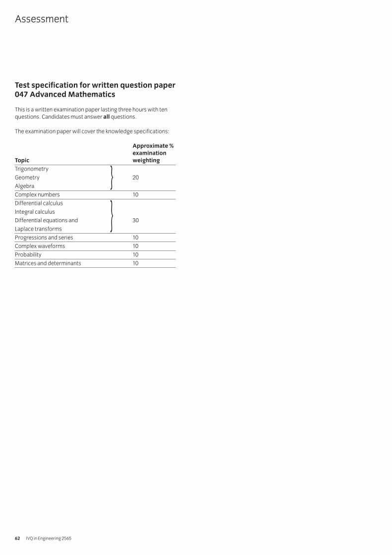
Test specification for written paperMechanical Principles (2565-03-026)
This is a written examination paper lasting one and a half hourswith five questions. Candidates must answer all 5 questions.
The examination paper will cover the knowledge specifications:
Approximate %
examination
Topic weighting
Statics 20
Stress and strain 20
Kinematics, dynamics and friction 40
Incompressible fluids 20
Assessment
IVQ in Engineering 256518
Introduction
The intention of this unit is to provide an opportunity forcandidates to solve a realistic engineering problem whichrequires the application and integration of other modules withinthe Advanced Diploma programme of study.
The aim of the unit is for candidates to acquire:
• planning, organisation and communication skills• experience in methods and techniques for product and process
improvement• and to develop personal qualities such as creative ability,
imagination, initiative and maturity.
Practical competences
The candidate must be able to do the following:
Specification and analysis
30.1 Select the problem to be solved.
30.2 Identify the main elements of the problem.
30.3 Define the objectives of the problem.
30.4 Prepare a specification of the problem to be solved.
30.5 Determine the tasks to be performed to enable theattainment of the objectives to be achieved.
30.6 Organise the tasks chronologically.
Scheduling and planning
30.7 Plan the initial programme for solving the problem.
30.8 Determine the resource requirements for each of the tasks.
30.9 Estimate the time needed to complete each task.
30.10 Prepare a schedule of work.
Execution and performance
30.11 Obtain the information necessary to solve the problem.
30.12 Select equipment or methods of operation to carry outeach task.
30.13 Perform experimental/investigatory work necessary forthe execution of the tasks.
Evaluation and communication
30.14 Evaluate the validity of the results.
30.15 Assess the success of the work undertaken.
30.16 Make recommendations for further work.
30.17 Prepare a project report to specified layout.Layout: eg title page, summary, contents page, list offigures, tables, symbols as required, introduction, workcarried out, evaluation of the results, conclusions asrelated to the aims of the project, practicalrecommendations, references, appendices.
30.18 Ensure that the body of the report includes the following work.Work: eg relevant background information, clear andprecise documentation of the aims of the project, relevanttheory, previous work undertaken by other people withinthe area of activity, the actual work undertaken.
30.19 Prepare material for an oral presentation.Materials: eg slides/transparencies, flip charts, audio orvideo tapes, supporting notes
030 Engineering Project Practical Assignment
Syllabus: 1998 edition 19
1 Competence references
30.1-30.19
2 Preparation
2.1 Location of test
The training centre or other venue where supervision andappropriate working conditions will be provided.
2.2 Requirements
Paper, pens, pencils and ruler or a computer system runningappropriate software (eg word processing, computer aideddraughting software) and a printer connected to the system,with paper loaded and set up ready to print.
Manuals for software.
Copy of section 3 and section 6.
2.3 Instructor notes
Candidates are required to select and solve individually anengineering problem which can realistically be achieved (seesection 6 for suitable suggestions) within 60 hours. Theproject must be agreed between candidate and instructorand must take into account the amount and level of workrequired and the resources available. The nature of the workmust demonstrate the candidate’s ability at advanceddiploma level.
The project is generally considered to be a student centredactivity. The instructor’s main responsibility is to create aneffective learning environment. In particular the instructorshould check the project objectives, monitor the candidate’sprogress, advise on project progression, exercise leadership ifneeded, assist in development of the candidate’s skills andknowledge and counsel as appropriate.
Candidates may carry out research and produce materialsduring the allocated time but the report must be produced atthe centre under supervision.
It is recommended that candidates should be allowedadequate time to produce the final report. Candidates mayuse word processors to produce their report provided theyhave sufficient word processing skills to do so efficiently.
On completion of the report, candidates are required to carryout an oral presentation of their work to the instructor andpeer group. It is envisaged that such a presentation will takebetween 15-30 minutes.
3 Candidates’ instructions
3.1 You are requested to select and solve a realisticengineering problem. At each stage of this project youmust refer to your instructor for continuous guidance anddirection. You must keep a log book summarising the workundertaken each week. This log book will be useful inproducing the final report. You have 60 hours to completethis assignment.
3.2 Select an appropriate project and agree it with your instructor.
3.3 Maintain on a regular basis a log book or diary detailingwork undertaken.
3.4 Identify the main elements of the problem to define theobjectives of the project.
3.5 Prepare a detailed specification of the problem andorganise the tasks to be undertaken chronologically(network diagram or similar).
3.6 Plan the initial programme for solving the problem anddetermine the resource requirements in terms of time,equipment and materials.
3.7 Prepare a schedule of the work to be carried out (Ganttchart or similar).
3.8 Undertake research in order to obtain the informationnecessary to solve the problem.
3.9 Select equipment or methods of operation to progress the project.
3.10 Carry out the work necessary for the completion of the project.
3.11 Evaluate the success of the work undertaken and makerecommendations for further work.
3.12 Prepare a project report using an appropriate format andlayout (see section 6.2), which should contain all the workproduced in 3.2-3.11 above.
3.13 Prepare an oral presentation and present it to yourinstructor/colleagues.Oral presentation: eg notes, overhead transparencies
3.14 Ensure your name is on the report and hand it in to your instructor.
030 Engineering Project Practical AssignmentPractical assignment 030/1: Solve an Engineering Problem
IVQ in Engineering 256520
4 Marking
4.1 Project completed in approximately 60 hours. ( )
4.2 Realistic engineering project selected and agreed with instructor. [ ]
4.3 Log book or diary maintained throughout the project. [ ]
4.4 The main elements of the problem identified and the objectives defined. [ ]
4.5
4.5.1 Detailed specification prepared. [ ]
4.5.2 Tasks to be undertaken organised chronologically. [ ]
4.5.3 Network diagram or similar produced. [ ]
4.6
4.6.1 Initial programme planned. [ ]
4.6.2 Resource requirements determined in terms of time, equipment and materials. [ ]
4.7 Schedule of work prepared (Gantt chart or similar). [ ]
4.8 Appropriate research undertaken and relevant information obtained [ ]
4.9 Appropriate equipment and methods to progress the work selected [ ]
4.10 Necessary work carried out to complete project. [ ]
4.11
4.11.1 Success of the project evaluated and work assessed. [ ]
4.11.2 Recommendations for further work made. ( )
4.12 Project report completed. [ ]
4.13 Oral presentation prepared and presented. [ ]
4.14 Report handed in. [ ]
5 Assignment completion
The candidate will have satisfactorily completed this assignmentif successful in all items marked with a [ ].
Candidates who fail to achieve the requisite number of outcomesshould be encouraged to carry out further work in order tocomplete the assignment satisfactorily.
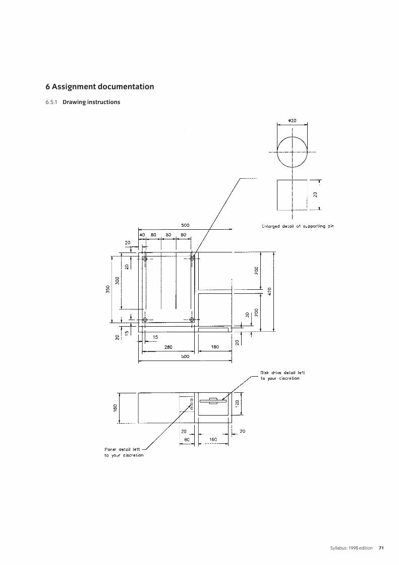
6 Assignment documentation
6.1 Choosing a project
The theme of the project is to investigate a particular sectionof a company and to improve the section in terms of costs orprocedures (manufacturing, maintenance, marketing,management). Possible areas for project work are listedbelow:
• improvement of the efficiency or effectiveness of anexisting process
• introduction and commissioning of new plant• modification of existing equipment to perform new or
additional operations• improvement of maintenance procedures on selected
plant or equipment• introduction of new procedures for measuring, testing and
calibrating products or equipment• standardisation of component parts for
product assembly.
6.2 Project report writing
The general layout of the project report should be as follows:
title pagesummarycontents pagelist of figures, list of tables, list of symbols, as requiredintroductionwork carried outevaluation of the resultsconclusions as related to the aims of the projectpractical recommendationsreferences and appendices.
The work carried out should include:
relevant background informationclear and precise documentation of the aims of the projectrelevant theoryprevious work undertaken by other people within the area ofactivitythe actual work undertaken
Syllabus: 1998 edition 21
Introduction
The technician engineer needs to possess an in-depthunderstanding of the behaviour, performance and processing oftraditional and modern engineering materials.
Knowledge requirements
Instructors must ensure that candidates are able to:
Steels and heat treatment of steels
33.1 Examine the iron-carbon equilibrium diagram and usingthe inverse lever rule calculate the ratios of differentstructures produced during various cooling cycles withdifferent carbon content.Structures: pearlite, martensite, austenite, ferrite, cementite
33.2 Explain the difference and identify the importance of therelationship between processing, properties, structuresand their uses.
33.3 Explain the effects of adding alloying elements to steels.Effects: increase in strength, increase in hardness,changes in other mechanical/physical propertiesElements: silicon, manganese, nickel, copper, cobalt,chromium, tungsten, molybdenum, vanadium, aluminium
33.4 Interpret time-temperature transformation diagrams andcontinuous cooling transformation diagrams to look atgrain structure effects/formation induced by differentcooling rates.
33.5 Describe the effects of quenching steels in terms of grainstructure formation.
33.6 Define hardenability.
33.7 Describe the procedures for carrying out a Jominy test andinterpreting the results.
33.8 Explain the heat treatment effects of a range of processes.Processes: tempering, annealing, martempering,austempering, surface hardening
Metals and alloys for casting
33.9 Describe the different alloys used for casting.Alloys: aluminium-silicon, magnesium, copper-tin, zinc diecasting, cast iron
33.10 State the factors to be considered when choosing an alloyfor casting.Factors: melting point, heat treatment effects,applications, weldability, machinability, fluidity
33.11 Examine the equilibrium diagram for aluminium-siliconalloy and use the inverse lever rule to calculate the variousstructures during cooling and identify the mechanicalproperties achieved.Properties: tensile strength, ductility, hardness
33.12 Explain the factors which influence failure of metals.Factors: creep, fatigue
Polymers
33.13 Identify the structure of a polymer as a combination ofmany small molecules to form large molecules resulting ina network chain.Structure: linear, branched, cross-linked chains, linearamorphous, folded linear, polymer chains
33.14 Explain how crystallinity occurs in polymers.
33.15 Explain melting temperature with respect to polymeric materials.
33.16 Explain the significance of glass transition temperature andstate typical values for a range of polymers.Polymers: polyethylene, polystyrene, polyvinyl chloride, polypropylene
33.17 Describe the features of a tensile test on a polymeric material.Features: non-linear stress/strain relationship,commencement of necking, cold drawn state
33.18 Describe internal and external plasticisation and list thechange in properties with plasticisers.Properties: tensile strength, ductility
33.19 Compare the mechanical properties of commonly usedpolymers and explain the effects of temperature.Properties: tensile strength, ductility
33.20 State basic methods of shaping polymers and typical applications.Methods: moulding, extrusion, vacuum forming, machining
33.21 State benefits of manufacturing products and componentsusing polymeric materials and typical applications.Benefits: range of shapes, final shape, finish achieved, lowtemperature process
33.22 Describe the extrusion process.
33.23 Describe the moulding processes.Processes: injection, compression, transfer
33.24 Describe the processes used for the production of film,sheet and hollow objects.Processes: slit-die extrusion, blow-film, blow moulding,rotational moulding
033 Materials and Processes
IVQ in Engineering 256522
33.25 Describe thermoforming processes and state typical applications.Processes: vacuum, pressure, mechanical
33.26 Describe the hand lay-up process using glass reinforcedplastic (GRP) and state typical applications.
33.27 Describe the process of producing component parts usingcarbon fibre.
Finishing processes
33.28 Sketch the structure of a grinding wheel and list types ofabrasive/grain size and bond.Abrasive: aluminium oxide, silicon carbide, cubic boron, diamondBond: vitrified, silicate, rubber, resinoid, shellac, metallic
33.29 Describe a typical abrasive wheel specification, eg A54M5V, and describe each part.
33.30 Describe the cutting action of an abrasive wheel.
33.31 Explain the terms ‘wheel structure’ and ‘wheel grade’.
33.32 Explain the principle of operation of a range of finishing processes.Processes: grinding, honing, lapping, super-finishing,polishing, buffing
Powder metallurgy
33.33 Describe the process stages of powder metallurgy.Stages: blending/mixing of the powder, compacting,sintering, sizing, impregnation (for porous materials), heat treatment
33.34 State the design advantages of powder metallurgy.Advantages: large quantities, controlled porosity, wide range of metals and alloys
Sheet metal processes
33.35 Describe the deep drawing process and state commondefects and typical applications, eg cans and sinks.
33.36 Describe types of presses.Types: gap frame, press brake, side frame
33.37 Describe various tube bending methods.Methods: stretch, draw, compression
33.38 Describe the process of spinning and state applications egcomponents, cooking utensils.
Alternative machining processes
33.39 Describe the electrochemical machining (ECM) process, state typical ECM applications their advantages and disadvantages.Advantages: use on very hard materials, no component burrs, low tool wear, no distortion, complex geometrical shapesDisadvantages: high consumption of electricity, cost,workpiece must be an electrical conductor
33.40 Describe the electric discharge machining (EDM) process,state typical applications their advantages and disadvantages.Advantages: removal of metal from delicate parts, hole drilling at acute angles, machining of hard metals, no distortion, complex geometrical shapesDisadvantages: tool wear could be a problem due to heatgeneration, work piece must be an electrical conductor
33.41 Describe the electric discharge wire cutting (EDWC)process and state typical applications.
Surface texture
33.42 State that surface texture is a geometrical property andexplain associated terms.Terms: lay, roughness, waviness
33.43 Calculate the surface roughness value given a simplesinusoidal shaped trace.Values: arithmetic mean value (Ra), root mean square (Rq)
33.44 State typical roughness values for standard machining processes.Processes: rough turning, finish turning, milling, drilling,grinding, honing
Syllabus: 1998 edition 23
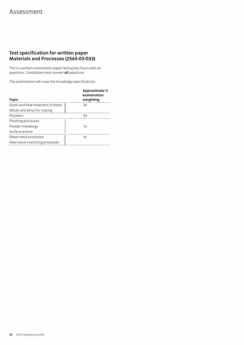
Test specification for written paperMaterials and Processes (2565-03-033)
This is a written examination paper lasting two hours with sixquestions. Candidates must answer all questions.
The examination will cover the knowledge specifications:
Approximate %
examination
Topic weighting
Steels and heat treatment of steels 34
Metals and alloys for casting
Polymers 34
Finishing processes
Powder metallurgy 16
Surface texture
Sheet metal processes 16
Alternative machining processes
Assessment
IVQ in Engineering 256524
}
}}
Introduction
This unit is divided into two parts. The first part is AdvancedManufacturing Systems. The second part is Management of theManufacturing Process.
Advanced Manufacturing SystemsThis section of the unit focuses on the application of computers inengineering with a particular emphasis on manufacturing.
Practical competences
The candidate must be able to do the following:
Computer numerical control (CNC)
34.1 Specify operation sequence using operation sheets.
34.2 Produce and check a part-program manually.
34.3 Produce and check a computer aided part-program.
34.4 Prepare, verify, correct errors as necessary, a part-programto produce particular features on a component using aCNC machine (milling machine or lathe).Features: (milling) internal and external, profiles, straight,angular, circular interpolation, slots, pockets; (lathe)external profiles, multi-diameters, chamfers, radii,undercuts, parting off, internal profiles, drilling, reaming,threaded holes
Knowledge requirements
Instructors must ensure that candidates are able to:
Computers in engineering
34.5 Identify engineering applications that affect the choice ofcomputer systems.Applications: design, draughting, financial control,inspection, manufacture, projects, process/stock control,testing, quality control
34.6 State the benefits and limitations of using a computeraided design system to create design drawings andproduct models.Benefits: repeatability, speed, simple editing, reducedstorage space, modificationsLimitations: cost of training and equipment
34.7 Describe a range of computer terms.Terms: central processing unit, hardware, software,random access memory (RAM), read only memory (ROM),files, program, network
34.8 Describe the main advantages and limitations of acomputer system.Advantages: cycle/feed times, reduced production costs,accuracy, best use of resources, information, productivity, qualityLimitations: high training and equipment costs
34.9 Describe the steps to develop and implement a computer system.Steps: commissioning, investment, forecasting, staffing,leasing, planning, training
CNC systems
34.10 Describe the needs and use of guards and interlockingdevices on CNC machines.
34.11 State the hazards associated with manual and automaticwork and tool changing.
34.12 State the problems associated with the removal of waste(swarf) from the working zone.
34.13 State procedures for the restarting of CNC machines afteremergency shutdown.
34.14 Explain the advantages and limitations of CNC machinetools over conventional tools.Advantages: high repeatability/accuracy, complex shapesLimitations: high equipment costs, specialist training
34.15 Identify the three basic axes of CNC machines.Axes: x, y, z
34.16 Explain the different coordinate systems of CNC machines.Co-ordinates: absolute, incremental, polar
34.17 Describe different types of datum used.Datum: shift on zero, fixed zero, floating zero
34.18 Describe the principle of open loop and closed looppositioning systems used on CNC machines.
34.19 Explain the CNC programming terms.Terms: subroutines, macros
34.20 Explain the difference between manual part-programmingand computer part-programming techniques.
34.21 Compare features of a high level programming languagewith equivalent machine code instructions.Features: ease of programming, speed and execution,storage and memory, cost
Flexible manufacturing systems
34.22 Describe typical manufacturing systems.Systems: jobbing shop, production workshop, stand-alone CNC machine tool, flexible manufacturing cell (FMC),flexible manufacturing systems (FMS), flowline and transfer line
034 Advanced Manufacturing and Management
Syllabus: 1998 edition 25
34.23 Explain how FMS compares with conventionalmanufacturing systems.
34.24 Describe the basic components of FMS and theirintegration in the data processing system.
34.25 Explain the integration of computer design withmanufacturing systems.
34.26 Compare the concept of flexible manufacturing cells (FMC)with flexible manufacturing systems (FMS).
34.27 List the advantages and limitations of FMC and FMS.Advantages: high machine tool utilisation, reduced lead times, reduced labour, reduced inventory, reducedwork in progress (WIP), parts produced randomly invarious batch sizesLimitations: high cost of system, specialist training
34.28 Explain how robots are used within the FMS system.
Computer aided manufacture (CAM)
34.29 State that computer-integrated manufacture (CIM) is thecomputerised integration of all aspects of design,planning, manufacturing, distribution and management.
34.30 Describe the benefits of CIM.Benefits: lower product cost, shorter product life cycle,rapid response to market demand, quality, improved use ofmaterials and machinery, reduced work-in-progress (WIP),improved employee utilisation
34.31 Identify the major stages involved in the use of computersto assist in all aspects of the manufacture of a product.Stages: design, draughting, processing, ordering,manufacturing, assembly, inspection, testing, storage, transport
34.32 Identify the elements of a CAM system.Elements: machine tools, material handling, toolhandling, production control and inspection
Management of the Manufacturing ProcessThis section of the unit focuses on planning, quality control,process management and people management.
Planning and control
34.33 Explain the terms ‘production planning’ and ‘production control’ and diagrammatically show the link between them.
34.34 Describe the functions of a typical production planning andcontrol system.Functions: master production schedule (MPS), bill ofmaterial (BOM), material requirement planning (MRP),capacity planning (CP), inventory records (IR), purchasingand manufacture
34.35 Describe a master production schedule.
34.36 Describe the function of a process planning sheet (routecard) and identify the information on it.Information: part number, part name, contract number,material, planning engineer, date, a brief description of theoperation performed, equipment, tooling, times
34.37 Identify factors related to the economics of componentmanufacture as opposed to purchasing from other sources(sub-contracted).Factors: eg reduced costs, loss of control
34.38 Explain the goals of ‘just in time’ (JIT) production.Goals: eliminate waste (materials, money, lead times,effort), receive supplies just in time to be used to produceparts, produce sub-assemblies just in time to be made intofinished products, produce and deliver finished productsjust in time to be sold
34.39 Describe the manufacturing requirements which areessential to achieving the aims of JIT and state the advantages.Requirements: product design for ease of manufacture,improved production control, multi-skilled workforce,flexible manufacturing, emphasis on qualityAdvantages: low inventory, easily corrected faults, lowerproduct cost
Quality control
34.40 Explain quality in terms of conformance to requirementsand fitness for use.
34.41 Examine several products and components and analysethe two quality requirements in terms of product featureand freedom from defects.Feature: design configuration, ease of use, aesthetic appeal, function and performance, reliability, durability, serviceabilityDefects: conformance to specification, componentswithin tolerance, no missing parts, no early failures
34.42 Explain the term ‘process capability.’
34.43 Use statistical process control techniques to analyseprocess variations.
Process management
34.44 State methods of process management.Methods: critical path analysis (CPA), linear programming
34.45 Describe the technique of critical path analysis.
34.46 Solve simple problems using critical path techniques.
34.47 Describe the technique of linear programming and areaswhere it is used, eg production schedule.
34.48 Explain why it is necessary to forecast product sales.
IVQ in Engineering 256526
34.49 Describe methods of forecasting.Methods: moving averages, weighted moving averages,exponential smoothing, exponential smoothing with trend adjustment
People management
34.50 Explain the meaning of ‘human resource management’.
34.51 Describe the personnel functions within a manufacturing company.Functions: job design, recruitment and selection,performance management, job evaluation and design ofpay structures
34.52 Describe the benefits of manpower planning.Benefits: to review the present levels of manning, torecruit personnel in good time, training programmes canbe prepared in advance, the implications of change can beassessed, redundancies can be anticipated or evenavoided by redeployment
34.53 State various theories of motivation.Theories: extrinsic, intrinsic, significance of needs/wants,influence of goals, importance of expectations, selfefficacy, behavioural theory, social learning theory,attribution theory, role modelling
34.54 Describe various leadership styles and give examples of each.Styles: exploitive authoritative, benevolent authoritative,consultative and participative group management
34.55 Explain the need for flexibility in the workplace.Need: to be competitive, to be adaptive, impact of newtechnology, new organisation structure
34.56 Explain why training is important within any organisation.
34.57 Describe methods of training, both on-the-job and off-the-job.Methods: demonstrations, skill practice, simulation,lectures and talks, discussions, tutorials, audio-visual aids,case studies, role-play exercises, business games, projects
34.58 State the health and safety aspects of employment.Aspects: safety of employees and public is of paramountimportance, safety takes place over expediency, everyeffort made to involve all employees in development andimplementation of health and safety procedures, healthand safety legislation complied with ‘in spirit’ as well asaccording to the letter of the law
Syllabus: 1998 edition 27
Test specification for written paperAdvanced Manufacturing and Management(2565-03-034)
This is a written examination paper lasting three hours with tenquestions. Candidates must answer all questions.
Approximate %
examination
Topic weighting
Computers in engineering 10
CNC systems 20
Flexible manufacturing systems 10
Computer aided manufacture (CAM) 10
Planning and control 10
Quality control 10
Process management 10
People management 20
Assessment
IVQ in Engineering 256528
1 Competence references
34.1, 34.3, 34.4
2 Preparation
2.1 Location of test
The training centre or other venue where supervision andappropriate working conditions will be provided.
2.2 Requirements
A computer aided draughting system with a mouse and alaser printer.
Computer Aided Manufacture software.
Computer Numerical Control Milling machine.
Materials as specified in drawing AMEE3A (see section 6).
Copy of section 3 and section 6.
2.3 Instructor notes
Instructors may produce the profile using CAD and
save it on disks for candidates to use, or may require
candidates to produce their own profiles.
The aim of this assignment is to produce/use a profile ofdrawing AMEE3A, transfer it to a CAM package, produce aCNC program, transfer it to a milling machine and machinethe profile.
Candidates are allowed 12 hours to complete thisassignment and may work alone or in small groups.
Instructors must monitor candidates’ work throughout the assignment.
3 Candidates’ instructions
3.1 You are required to produce/use a profile of drawingAMEE3A, transfer it a CAM package, produce a CNCprogram transfer it to a milling machine and machine theprofile. You are allowed 12 hours to complete thisassignment and may work alone or in small groups. Readthe instructions carefully and if you do not understandanything then ask your instructor.
Check with your instructor before commencing whetheryou are required to produce a profile of drawing AMEE3Aor use a profile which your instructor has produced andsaved on disk.
3.2 Produce/use a profile of drawing AMEE3A.
3.3 Complete the Operation Sheet (see section 6) to include:
3.3.1 machine sequence
3.3.2 tools required
3.3.3 work holding and/or fixtures
3.3.4 calculations including speeds and feeds.
3.4 Tabulate co-ordinates:
3.4.1 draw up a list of co-ordinates using sheet A (see section 6)
3.4.2 show all calculations on sheet B (see section 6).
3.5
3.5.1 Transfer profile of drawing AMEE3A to CAM package.
3.5.2 Produce a draft CNC program and store on disk.
3.6 Plot the programmed tool path.
3.7 Edit the program and produce a listing.
3.8 Transfer the program to a milling machine, set tool offsetsand machine the profile.
3.9 Calculate the time to produce component and comparethe calculated time with the actual machining time.
3.10 Put your name on your work and hand it in to the instructor.
035 Advanced Manufacturing Engineering Practical AssignmentsPractical assignment 035/1: Operate a CAM System
Syllabus: 1998 edition 29
4 Marking
4.1 Assignment completed within 12 hours. ( )
4.2 A profile produced/used of drawing AMEE3A using CAD. [ ]
4.3 An Operation Sheet produced to include:
4.3.1 machine sequence [ ]
4.3.2 tools required [ ]
4.3.3 work holding and fixtures [ ]
4.3.4 calculations including speeds and feeds. [ ]
4.4 Co-ordinates tabulated:
4.4.1 a list of co-ordinates drawn up using sheet A(section 6) [ ]
4.4.2 all calculations shown on sheet B (section 6). [ ]
4.5
4.5.1 Profile transferred to CAM package. [ ]
4.5.2 A draft CNC program produced and stored on disk. [ ]
4.6 The programmed tool path plotted. [ ]
4.7 The program edited and a listing produced. [ ]
4.8 The program transferred to a milling machine, tool offsets set and the profile machined. [ ]
4.9 The time to produce component calculated and the calculated time compared with the actual machining time. ( )
4.10 Work handed in to the instructor. [ ]
5 Assignment completion
The candidate will have satisfactorily completed this assignmentif successful in all the items marked with [ ].
A period of several days must elapse before an unsuccessfulcandidate may retake this assignment.
IVQ in Engineering 256530
6 Assignment documentation
6.1 Machining sequence for flange – Operation Sheet
Sketches of work holding and fixtures
Syllabus: 1998 edition 31
SEQUENCE NO OPERATION TOOLS & FIXTURE
FIRST SETUP SECOND SETUP
6 Assignment documentation
6.2 Sheet A – tabulated co-ordinate list
Tabulate the absolute X-Y co-ordinates of points (‘B’ to ‘Y’) with respect to the X-Y zero point at ‘A’.
IVQ in Engineering 256532
Position X Co-ordinate Y Co-ordinate
A 0.00 0.00
B
C
D
E
F
G
H
I
J
K
L
M
N
O
P
Q
R
S
T
U
V
W
X
Y
Z
6 Assignment documentation
6.3 Sheet B – show speeds and feeds calculations here.
Syllabus: 1998 edition 33
Operation Tool No DIA ‘S’ m/min RPM Feed/min
For high speed tooling and the material as aluminium take ‘S’ to be 40 m/min and the feed per tooth to be 0.05 mm.
6 Assignment documentation
6.4 Drawing AMEE3A
IVQ in Engineering 256534
1 Competence reference
34.1, 34.2, 34.4
2 Preparation
2.1 Location of test
The training centre or other venue where supervision andappropriate working conditions will be provided.
2.2 Requirements
Computer Numerical Control Milling machine.
Materials as specified in drawing AMEE3B (see section 6).
Copy of section 3 and section 6.
2.3 Instructor notes
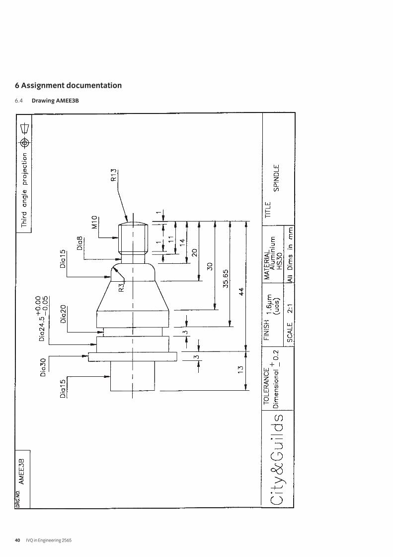
The aim of this assignment is to write a CNC programme toproduce a spindle (see drawing AMEE3B – section 6) andmachine the profile.
Candidates are allowed 8 hours to complete this assignmentand may work alone or in small groups.
Instructors must monitor candidates’ work throughout the assignment.
3 Candidates’ instructions
3.1 You are required to write a CNC programme manually toproduce a spindle (see drawing AMEE3B – section 6) andmachine the profile.
You are allowed 8 hours to complete this assignment and may work alone or in small groups. Study drawing AMEE3B.
3.2 Produce an Operation Sheet (see section 6) to include:
3.2.1 machine sequence
3.2.2 tools required
3.2.3 work holding and fixtures
3.2.4 calculations including speeds and feeds.
3.3 Tabulate co-ordinates:
3.3.1 draw up a list of co-ordinates using sheet A (see section 6)
3.3.2 show all calculations on sheet B (see section 6).
3.4 Write a programme to produce the spindle.
3.5 Manually input the programme and edit it.
3.6 Set tool offsets.
3.7 Set the lathe into machine mode and complete a dry runusing single step mode.
3.8 Set machine to autocycle mode and machine ‘first off’ inwax, polystyrene, or any other suitable material.
3.9 Machine actual component.
3.10 Put your name on your work and hand it in to the instructor.
035 Advanced Manufacturing Engineering Practical AssignmentsPractical assignment 035/2: Write a Programme Manually to Produce a Spindle
Syllabus: 1998 edition 35
4 Marking
4.1 Assignment completed in 8 hours. ( )
4.2 An Operation Sheet produced to include:
4.2.1 machine sequence [ ]
4.2.2 tools required [ ]
4.2.3 work holding and fixtures [ ]
4.2.4 calculations including speeds and feeds. [ ]
4.3 Co-ordinates tabulated:
4.3.1 a list of co-ordinates drawn up using sheet A [ ]
4.3.2 all calculations shown on sheet B. [ ]
4.4 A programme written to produce the spindle. [ ]
4.5 The programme manually input into the machine and edited. [ ]
4.6 Tool offsets set. [ ]
4.7 The lathe set into machine mode and a dry run completed using single step mode. [ ]
4.8 Machine set to autocycle mode and ‘first off’ machined in wax, polystyrene, or other suitable material. [ ]
4.9 Actual component machined. [ ]
4.10 Work handed in to the instructor. [ ]
5 Assignment completion
The candidate will have satisfactorily completed this assignmentif successful in all the items marked with [ ].
A period of several days must elapse before an unsuccessfulcandidate may retake this assignment.
IVQ in Engineering 256536
6 Assignment documentation
6.1 Machining sequence for a spindle – Operation sheet
Syllabus: 1998 edition 37
SEQUENCE NO OPERATION TOOLS & FIXTURE
FIRST SETUP SECOND SETUP
6 Assignment documentation
6.2 Sheet A – tabulated co-ordinate list
Tabulate the absolute X-Y co-ordinates of points (‘B’ to ‘Y’) with respect to the X-Y zero point at ‘A’.
IVQ in Engineering 256538
Position X Co-ordinate Y Co-ordinate
A 0.00 0.00
B
C
D
E
F
G
H
I
J
K
L
M
N
O
P
Q
R
S
T
U
V
W
X
Y
Z
6 Assignment documentation
6.3 Sheet B – show speeds and feeds calculations here.
Sketches of work holding and fixtures
Syllabus: 1998 edition 39
For high speed tooling and the material as aluminium take ‘S’ to be 40 m/min and the feed per tooth to be 0.05 mm.
Operation Tool No DIA ‘S’ m/min RPM Feed/min
6 Assignment documentation
6.4 Drawing AMEE3B
IVQ in Engineering 256540
Introduction
This unit is divided into two parts. The first part is Advanced PlantTechnology and the second part is Plant MaintenanceProcedures.
Advanced Plant TechnologyThis section of the unit is designed to give candidates aknowledge of the construction and operation of plant, the relatedtheoretical principles and performance calculation procedures.Health and safety procedures must be emphasised throughoutthis unit.
Practical competences
Candidates must be able to do the following:
38.1 Draw line diagrams of a given steam generation and power plant.
38.2 Identify the components and state their function andprinciples of operation.
38.3 Draw line diagrams to show the layout of a givenrefrigerated building and the details of vapourcompression refrigeration units.
38.4 Calculate co-efficient performances, refrigeration effecting and refrigerating load for a vapour compression refrigerator.
Knowledge requirements
Instructors must ensure that candidates are able to:
Combustion
38.5 Calculate the percentage analysis by mass of ‘wet’ and‘dry’ products of the complete combustion of solid andliquid fuels where excess air is supplied.
38.6 Explain why it is usual to quote only the ‘dry’ products.
38.7 Calculate the percentage analysis by volume of ‘wet’ and ‘dry’ products of a gaseous fuel where excess air is supplied.
38.8 Define higher and lower calorific value.
38.9 Calculate the higher calorific value of a fuel given thecalorific value of the constituent parts.
38.10 Define the properties of a liquid fuel.Properties: flash point, ignition temperature, octane andcetane number
Refrigeration
38.11 State the main elements of a vapour compressionrefrigerator and explain with the aid of a block diagram its operation.Elements: compressor, condenser, throttle valve, evaporator
38.12 Sketch the cycle of operation of a vapour compressionrefrigerator on a pressure/enthalpy diagram and describethe stages.Stages: compression, condensation, expansion, evaporation
38.13 Explain that an isentropic process is a constanttemperature entropy process.
38.14 State that for ideal conditions the compression of therefrigerant in a vapour compression refrigerator is isentropic.
38.15 Solve problems to find the temperature of the refrigerantafter isentropic compression.
38.16 Define a range of refrigeration terms.Terms: co-efficient of performance (COP), refrigeratingeffect, refrigerating load (tonnes of refrigerant)
38.17 Explain the effect on refrigeration of undercooling aftercondensation and superheating after compression.
38.18 Solve problems on a range of terms using tables of thermo-dynamic and transport properties of fluids (eg. Mayhewand Rogers).Terms: co-efficient of performance (COP), refrigeratingeffect, refrigerating load
38.19 State the main elements of a vapour absorptionrefrigerator and explain with the aid of a block diagram its operation.Elements: pump, heater element, throttle valve, evaporator
38.20 State the properties of commonly used refrigerants givingtheir advantages and disadvantages.Refrigerants: ammonia, refrigerant 409 A (409 A replacesFreon 12 and has similar characteristics)
38.21 Describe the methods of leak detection for refrigerants.Refrigerants: ammonia, refrigerant 409 A
38.22 Explain what is meant by the terms ‘direct’ and ‘indirect’ refrigeration.
38.23 Explain how a control system operates in a refrigerator.
038 Plant Technology and Maintenance Procedures
Syllabus: 1998 edition 41
38.24 Demonstrate a knowledge of safe procedure and workingpractices in a refrigeration plant.Safe procedures: gas masks, check for leaks, permit towork, pressure vessels, non-spark toolsWorking procedures: purifying system, correct labelling of refrigerants, disposal of refrigerants,refrigerant recharging
Thermal insulations of buildings and furnaces
38.25 Explain the need for the insulation of buildings and furnaces.
38.26 Describe methods of insulating buildings, furnaces andcold rooms.Methods: cladding, fire bricks, refractory rending, cork panelling
38.27 Explain the meaning of the term ‘heat transfer coefficient’(U value) and recognise that all materials have specific values.
38.28 Evaluate the overall U value for a composite wall given theindividual values of each layer.
38.29 Calculate total heat transfer from the buildings, furnaces and cold rooms given all relevant information.Information: dimensions, materials, U values, surface temperatures
38.30 Solve problems in cost saving after insulation has beencarried out.
Steam generation
38.31 Derive an expression for the equivalent evaporation of a steam generating plant ‘from and at 100°C’ and state that generators are rated as actual evaporation and equivalent evaporation.
38.32 Solve problems involving steam generation, plantefficiency, equivalent evaporation and the amount of heattransferred in the economiser, evaporator, superheater.
38.33 Draw up an energy balance on a percentage basis for asteam generating plant, consisting of an economiser,evaporator and super heater.
38.34 Explain where energy losses occur in the plant and howthese losses can be minimised.Losses: flue gases, radiation, incomplete combustion, air ingress
38.35 State the factors affecting the thermal efficiency of steamgeneration.Factors: air ingress, poor firing equipment, fouling of heattransfer surfaces, excess air
38.36 State reasons for controlling the upper and lower limits offeedwater temperature flowing through an economiser.
38.37 Calculate outlet temperatures of feedwater fromeconomisers given inlet temperatures and flue gas conditions.
38.38 Explain briefly external methods of water treatment.Methods: sedimentation, filtration, precipitationsoftening, ion exchange system
Steam power plant
38.39 Explain the difference between steam for process andsteam for power.
38.40 Explain the use of back pressure, pass out and condensingturbines for supplying both power and process steam.
38.41 Explain the use of a reducing valve and de-superheater toby-pass a turbine when a required steam demand has to bemet for process work.
38.42 Explain the reasons why the largest heat loss occurs in the condenser.
38.43 Carry out calculations to show that the largest heat lossoccurs in the condenser.
38.44 Explain how a vacuum is produced and maintained in a condenser.
38.45 Explain the need for cleaning condenser tubes on a regular basis.
38.46 State the effects of cooling water leakage into the condensate.
38.47 Solve problems involving rate of flow of cooling water in acondenser given steam conditions and flow rates.
38.48 Explain why throttling is a wasteful process and the turbinecan be used to reduce steam pressure for process work.
38.49 Explain why most heat exchangers are contra-flow.
38.50 Explain why a low exhaust pressure is important if a turbineis to develop maximum power.
Steam utilisation
38.51 Explain what is meant by the term ‘flash steam’ and statethat flash steam may be generated from high pressure andhigh temperature condensate.
38.52 Calculate the quantity of ‘flash steam’ produced from given values.Values: pressures, temperatures, and flow rates
38.53 Describe the construction of a typical ‘flash steam’ vessel.
38.54 Describe the application of thermostatic control to items incommon use.Items: heating calorifiers, constant temperature heaters
IVQ in Engineering 256542
38.55 Describe the harmful effect of air in a steam plant and explain how air enters the system and how it can be removed.
Prime movers
38.56 State the various types of prime movers.Types: electric motor, CI and SI engines, steam, gas turbines
38.57 State the factors that should be considered when selecting a prime mover.Factors: cost, power requirement, availability, energy source, mass, efficiency, maintenancerequirement, environment
38.58 Describe the need for various services to prime movers.
38.59 Select a prime mover for a given purpose and justify thechoices made.
38.60 Explain that some prime movers are more suitable forstand-by emergency equipment.
SI and CI engines
38.61 Explain engine performance criteria.Criteria: indicated and brake power, mechanicalefficiency, thermal efficiency, specific fuel consumption
38.63 Draw up a heat balance on a percentage basis from giventest data.
38.64 Draw a graph of brake power against mechanicalefficiency, thermal efficiency and specific fuel consumptionto show the characteristics of both types of engines underfull-load conditions and compare the results.
Gas turbines
38.65 Explain the advantages limitations and applications of anopen circuit gas turbine plant.Advantages: high power outputs, utilisation of hotexhaust gases, fast start-up time to fuel loadLimitations: low thermal efficiency, automatic devicesrequired because of high temperatures and speedApplications: aircraft engines, stand-by plant, marine propulsion
38.66 Explain the difference between an open circuit and closedcircuit system and give advantages of the closed system.
38.67 Explain with the aid of a p/v diagram the cycle of operationfor a gas turbine.
Steam turbine
38.68 Explain the basic principle of operation of steam turbines.
38.69 State that turbines are classified as ‘impulse’ and ‘reaction’and explain their differences.
38.70 Explain why it is essential to use superheated steam forturbine operations.
38.71 Describe pressure and velocity compounding.
38.72 Describe the advantages, limitations and applications ofsteam turbines.Advantages: low pressure steam can be used, high powerfor comparatively small units, flow processLimitations: low thermal efficiency compared with CI enginesApplications: generation of electrical power
38.73 Solve simple problems in determining power outputthermal efficiencies.
Electric motors
38.74 Explain the basic principles of operation of electric motors.
38.75 Explain the advantages, limitations and applications ofelectric motors.Electric motors: dc motors (shunt and series), ac motors(induction and synchronous)
38.76 Explain why the overall efficiency of a motor fromgeneration to output is about 30 percent.
38.77 Solve problems for power outputs in single and threephase induction motors given voltage, current and power factor.
38.78 Solve problems involving power factor correction whenusing capacitors or synchronous motors.
Illumination
38.79 Explain a range of illumination terms and units used inlighting design.Terms: luminous flux, luminous intensity, illuminance,luminance, luminosity, glare, efficacy, reflectance, colour renderingUnits: lumen, candela, lux
38.80 Demonstrate a knowledge of the use of an illuminancemeter and a luminance meter.
38.81 Describe, with the aid of diagrams, the main constructionalfeatures of a range of lamps.Lamps: filament, fluorescent, sodium
38.82 Compare a range of lamps in the following terms.Terms: efficacy, rated life, colour rendering, mainapplications, cost
38.83 Explain how stroboscopic and flicker effects fromdischarge lamps may be reduced.
38.84 Select from standard codes suitable illuminance levels forparticular plant situations.
Syllabus: 1998 edition 43
38.85 Define the terms ‘utilisation factor’ (UF)’ and ‘maintenancefactor’ (MF)
38.86 Explain the ‘lumen’ method of design and calculate thenumber of lamps required for a particular situation.
Plant Maintenance ProceduresThis section focuses on health and safety codes of practice,maintenance systems, maintenance control and fault diagnosis.Reference should be made to BS 3811:1984 ‘MaintenanceManagement Terms in Terotechnology’ and BS 4778:1991 ‘QualityVocabulary’ or the corresponding International Standards.
Knowledge requirements
Instructors must ensure that candidates are able to:
Health and safety
38.87 Explain the classification of fires and for each class statethe type of extinguisher that should be used.Classes: A, B, C, D
38.89 Explain the main requirements of statutory codes of safety.Codes: guarding of machinery, use of abrasive wheels,chemical hazards
Maintenance systems
38.90 Explain the aims of maintenance management and theobjectives of a maintenance organisation.
38.91 Describe maintenance systems and draw a ‘family tree’ toshow how they are grouped.Systems: planned, unplanned, preventive, scheduled,condition-based, corrective (including emergency)
38.92 Make comparisons between planned and unplanned maintenance.Comparisons: materials, lost production, labour
38.93 Describe the resources required to operate a preventivemaintenance programme effectively.Resources: suitable workshop and equipment, tools, testequipment, spares, materials, trained personnel, reference data
38.94 Describe the steps to be taken before preventivemaintenance is commenced, and the procedures thatshould be implemented on completion.
38.95 Describe the activities that are included in a scheduledmaintenance programme.Activities: cleaning, lubrication, replenishment,adjustment, testing, inspection, reconditioning,replacement of ‘lifted’ components, inclusion of modifications
38.96 Write typical maintenance schedules for items of plant.Items: prime mover, compressor, machine tool
38.97 Explain the purpose of condition monitoring and describetypical methods used.Methods: recording, (temperature, vibration, noise),spectrographic oil analysis, particle retrieval, relativedisplacement measurement)
38.98 Explain the purpose of corrective maintenance anddistinguish between the terms used.Terms: symptoms, fault description, diagnosis of the cause
Maintenance control
38.99 Describe the application of a computerised system formaintenance data processing.Application: tasks undertaken, organisationalarrangements, effects on other sections of the factory,cost effectiveness
38.100 Explain the concept and importance of reliability and theconsequences of unreliability in both hardware andsoftware systems.
38.101 Explain reliability characteristics and the concept offailure classification.Characteristics: reliability, mean life, failure rate, mean time to failure (MTTF), mean time between failures (MTBF)
38.102 Solve problems relating to characteristics in 38.101.
38.103 Distinguish between the terms ‘fault’ and ‘failure’.
38.104 Draw and interpret typical failure-time ‘bathtub’ curves.
38.105 Explain the concept of availability and maintainability.
38.106 Describe the effect of obtaining improved reliability and maintainability.
IVQ in Engineering 256544
Fault diagnosis
38.107 Explain the basic principles of determining the primecause of a fault.Principles: knowledge and understanding, experienceand expertise, step-by-step strategy
38.108 Describe the stages of logical fault finding and rectification.Stages: collection and collation of defect data, plantinformation and resources, analysis of evidence, use offault location techniques, diagnosis and classification ofcause, rectification of fault (repair or replace), functional checks
38.109 Describe defect recording procedures.Procedures: completion of standardised report, recommendations, distribution to appropriate departments
Syllabus: 1998 edition 45
Test specification for written paperPlant Technology and MaintenanceProcedures (2565-03-038)
This is a written examination paper lasting three hours with tenquestions. Candidates must answer all questions.
The examination will cover the knowledge specifications.
Approximate %
examination
Topic weighting
Combustion 5
Refrigeration 15
Thermal insulation 5
Steam generationSteam power plant 20Steam utilisation
Prime moversSI and CI enginesGas turbines 20Steam turbinesElectric motors
Illumination 5
Heath and safetyMaintenance systems 20Maintenance control
Fault diagnosis 10
Assessment
IVQ in Engineering 256546
}
}
}
1 Competence reference
38.1, 38.2
2 Preparation
2.1 Location of test
The training centre or other venue where supervision andappropriate working conditions will be provided.
2.2 Requirements
Writing materials, drawing board and Tee square ordraughting machine or a computer system runningappropriate software (eg word processing, computer aideddraughting software) and a printer connected to the system,with paper loaded and set up ready to print.
Manuals for software.
Copy of section 3 and section 6.
2.3 Instructor notes
In this assignment candidates are required to write a reporton a steam generation and power plant (see section 6).
Candidates should be encouraged to use the computerfacilities to complete this assignment. The time allocated is 6 hours.
3 Candidates’ instructions
3.1 The time allowed for this assignment is 6 hours. Theassignment is based on steam generation and powerplant. The details are shown in section 6.
You are advised to read all the instructions beforecommencing work. If you do not understand all theinstructions then please ask the instructor.
3.2 Draw a line diagram of the plant showing steam,condensate pipelines and traps. Include in the line diagramall necessary fittings and equipment for the safe andefficient running of the plant.
3.3 On the line diagram, show how the high pressure steamcould be utilised to heat up the chemicals when the turbineis shut down for maintenance.
3.4 Explain using the diagram how the chemical in heatexchanger B could be kept at a constant temperatureduring transit.
3.5 Name the type of steam trap which should be used toaccommodate the heavy condensate load produced inheat exchangers C and D.
3.6 Describe a method of lifting the condensate efficiently tothe storage tank.
3.7 Produce a brief report and include the line diagram and theinformation produced in 3.3-3.6.
3.8 Ensure that your name is on the report and hand it in to the instructor.
039 Advanced Plant Practical AssignmentsPractical assignment 039/1: Steam Generation and Power Plant
Syllabus: 1998 edition 47
4 Marking
4.1 Assignment completed in 6 hours. ( )
4.2 A line diagram of the plant produced showing steam,condensate pipelines, traps and all necessary fittings and equipment for the safe and efficient running of the plant. [ ]
4.3 Utilisation of the high pressure steam to heat up the chemicals when the turbine is shut down formaintenance shown on the line diagram. [ ]
4.4 How the chemical in heat exchanger B could be kept at a constant temperature during transit explained. [ ]
4.5 The type of steam trap which should be used toaccommodate the heavy condensate load produced in heat exchangers C and D named. [ ]
4.6 Efficient lifting of this condensate described. [ ]
4.7 Report including diagram and information relating to 4.3-4.6 produced. [ ]
4.8 Report handed in to the instructor. [ ]
5 Assignment completion
The candidate will have satisfactorily completed this assignmentif successful in all items marked with a [ ].
Candidates who fail to achieve the requisite number of outcomesshould repeat the assignment using an alternative set of data.
6 Assignment documentation
Steam produced by two in-line boilers is used for electrical power production and process heating. The boilers supply steamat 25 bar and 350°C to a back pressure turbine which exhaustssteam at 9 bar with a dryness fraction of 0.95. This exhaust steamis transported through a pipeline 150m long to heat up variouschemicals passing through four separate heat exchangers A, B, Cand D.
From heat exchanger A, the condensate produced is dischargedinto a flash steam vessel which is at 3 bar. The flash steam is thenused for space heating in another part of the plant. Thecondensate from the flash vessel is discharged together with thecondensate from the other heat exchangers into a storage tank2m above the exchanges where it is indirectly cooled. It is thenreturned to the power plant as boiler feedwater.
A chemical with a low specific heat capacity has to be pumpedfrom heat exchanger B a distance of 100m and has to be kept at aconstant temperature whilst being moved. The masses of thechemicals passing through the heat exchangers C and D can varyimmensely over any 24 hour period, producing a heavycondensate load at times.
IVQ in Engineering 256548
1 Competence reference
38.3, 38.4
2 Preparation
2.1 Location of test
The training centre or other venue where supervision andappropriate working conditions will be provided.
2.2 Requirements
Writing materials, drawing board and Tee square or
draughting machine or a computer system runningappropriate software (eg word processing, computer aideddraughting software) and a printer connected to the system, loaded and ready to print.
Tables of thermodynamic and transport properties of fluids.
Copy of section 3 and section 6.
Formulae sheet showing details of formulae andrelationships.
2.3 Instructor notes
In this assignment candidates are required to draw and labela refrigerated warehouse (see section 6) and calculate theenergy transfer, the capacity of the refrigeration unit and itsco-efficient of performance.
Instructors must provide candidates with details of formulaeand relationships required (Formulae sheet). Instructorsmust also check candidates’ calculations at each stage.
Candidates should be encouraged to use the computerfacilities to complete this assignment. The time allocated forthis assignment is 9 hours.
3 Candidates’ instructions
3.1 The time allowed for this assignment is 9 hours. You arerequired to produce a report on a refrigerated warehouse,see details in section 6. You may use a word processor andcomputer aided draughting software to carry out theassignment. Make sure you have a copy of the Formulaesheet and that you check your calculations with yourinstructor at each stage.
You are advised to read all the instructions beforecommencing work. If you do not understand all theinstructions then please ask the instructor.
3.2 Draw a labelled line diagram showing the layout of thewarehouse and refrigeration unit within its building. Thediagram should show the evaporator, condenser, throttler, compressor and how the brine is pumped around the warehouse using a manifold system to give a uniform distribution.
3.3 Calculate using the relevant equations (see Formulaesheet) and the given data:
3.3.1 the energy transferred per minute through thefabric of the warehouse
3.3.2 the minimum capacity required of the refrigerationunit in tonnes of refrigeration.
3.3.3 the co-efficient of performance (COP) of the refrigerator.
3.4 Produce a brief report on the refrigerated warehouse andinclude the line diagram with details of calculationsperformed and final results obtained.
3.5 Hand in the report to the instructor.
039 Advanced Plant Practical AssignmentsPractical assignment 039/2: Calculate heat transference and refrigeration requirements tokeep a building at a constant temperature
Syllabus: 1998 edition 49
4 Marking
4.1 Assignment completed in 9 hours. ( )
4.2 A line diagram showing all the necessary features of the building and correctly labelled evaporator, condenser, throttler and compressor. The diagram must show how the brine is chilled and the brine is pumped around the warehouse using a manifold system to give a uniform distribution. [ ]
4.3 The following calculations carried out:
4.3.1 The energy transferred per minute through thefabric of the warehouse correctly calculated. [ ]
4.3.2 The minimum capacity required for the refrigeration unit in tonnes of refrigeration. [ ]
4.3.3 The co-efficient of performance (COP) correctly calculated. [ ]
4.4 Report produced which includes line diagrams with details of calculations performed and final results obtained. [ ]
4.5 Work handed in to the instructor. [ ]
5 Assignment completion
The candidate will have satisfactorily completed this assignmentif successful in all items marked with a [ ].
Candidates who fail to achieve the requisite number of outcomesshould repeat the assignment using an alternative set of data.
6 Assignment documentation
A refrigerated warehouse has internal dimensions of width 12m,length 50m and height of 5m to the eaves. The centre ridge of theroof runs the full length of the building and the roof has a pitch of30°. The warehouse is to be kept at 2°C by an indirectrefrigeration system using brine to circulate around pipe fixed tothe walls. The refrigeration unit is to be installed in a buildingadjacent to it and the primary refrigerant used is ammonia.
There are two air changes per hour, due to produce beingtransported in and out of the warehouse, and the outside airtemperature is on average 15°C. (Underfloor temperature to betaken as the same as outside).
Necessary data.
Heat transfer coefficients W/m2K
Insulated walls and ceiling 0.06
Concrete floor 0.4
Doors to be considered as walls
Density of air 1.2 kg/m3
Specific heat capacity of air 1.01 kJ/kg K
1 tonne of refrigeration 233 kJ/min
Pressure range of refrigerant 1.447 bar to5.346 bar
Temperature after isentropic compression 56°C
Refrigerant undercooled 4°C
Refrigerant leaves evaporator dry saturated
Efficiency of brine chiller 90%
IVQ in Engineering 256550
Introduction
This unit is divided into two parts Plant Hydraulics and Plant Pneumatics.
It is recommended that the teaching of hydraulic and pneumaticcomponents and circuits should be delivered by practical workusing hydraulic and pneumatic rigs. Candidates should preparebasic circuits to discuss and demonstrate the characteristics ofhydraulic/pneumatic components and their interconnection.
Plant HydraulicsThis section of the unit covers hydraulic theory and hydrauliccomponents and circuits.
Practical competences
Candidates must be able to do the following:
40.1 Select an appropriate industrial hydraulic system andidentify its function.
40.2 Identify hydraulic system components using standard terminology.
40.3 Prepare circuit diagrams using manual or computer aideddraughting system.
40.4 Explain the operation of the hydraulic circuits and themajor components.Components: pumps, actuators, directional controlvalves, flow control valves, pressure control valves
40.5 Use appropriate formulae and nomograms to obtain circuitparameters.Parameters: working pressure, maximum load capacity ofactuators, actuator speed, flow rates, pipe size
Knowledge requirements
Instructors must ensure that candidates are able to:
Hydraulic theory
40.6 Identify symbols recommended by CETOP (BS or ISO) forcircuit diagrams.
40.7 Explain and use the formulae and nomograms todetermine circuit parameters.Parameters: working pressure, maximum load capacity ofactuators, actuator speed, flow rates, pipe size
Hydraulic components and circuits
40.8 Draw a circuit diagram to show the layout of a basichydraulic circuit and explain the function of each element.Element: reservoir, pump, relief valve, control valves,actuator
40.9 Describe the construction and operation of commonlyused pumps in a circuit and compare their performancecharacteristics.Pumps: vane and piston (including variable types), gear
40.10 Describe the construction and operation of actuators.Actuators: linear, rotary, semi-rotary
40.11 Identify the various types of seals used in hydraulicsystems and explain the reasons for the choice ofmaterials.
40.12 State and compare the characteristics of hydraulic motors.Characteristics: torque, power, speed
40.13 Describe the construction of a reservoir and explain thepurpose of each fitting.Fitting: oil level indicator, breather, filling-cap, drain plug,baffle plate
40.14 Describe the construction, operation and application ofaccumulators.Accumulators: deadweight, spring loaded, gas charged
40.15 State the properties of a typical hydraulic fluid.Properties: viscosity, lubricity, toxicity
40.16 Describe the merits and limitations of a range of hydraulic fluids.Hydraulic fluids: mineral oil, emulsions, water, glycol mix, synthetics
40.17 Explain the necessity of filtration in hydraulic systems andthe methods of rating filters (b values).
40.18 Describe the types of filters used and state their locationwithin a system.Types: surface, depth
40.19 Describe fluid conductors and associated joints and fittings.Fluid conductors: pipe, tube, flexible hose
40.20 Describe the construction, operation and application ofdirectional control valves.Valves: poppet, spoolApplication (centre types): closed, open, floating,tandem, regenerative
40.21 Describe methods of valve actuation.Methods: manual, mechanical, electrical, pneumatic,electro-hydraulic
040 Plant Hydraulics and Pneumatics
Syllabus: 1998 edition 51
40.22 Explain the construction, operation and application ofpressure control valves.Valves: relief, reducing, unloading, sequence, counter balance
40.23 Describe the construction, operating and application offlow control valves.Flow control valves: non-compensated, pressure compensatedFlow control (methods): meter-in, meter-out, bleed-off
40.24 Describe the construction, operation and application ofcheck valves and pilot operated check valves.
40.25 Design circuits based on standard components to meetgiven control requirements eg lifting equipment andmachine tools, simple process plant control.
Plant PneumaticsThis section of the unit covers compressed air theory andpneumatic components and circuits.
Practical competences
Candidates must be able to do the following:
40.26 Prepare circuit diagrams using manual or computer aideddraughting systems.
40.27 Identify pneumatic system components using standard terminology.
40.28 Select an appropriate pneumatic system and identify its function.
40.29 Explain the operation of the pneumatic circuits and themajor components.Components: compressors, actuators, directional controlvalves, flow control valves, pressure control valves
40.30 Use appropriate formulae and nomograms to obtaincircuits parameters.Parameters: working pressure, maximum load capacity ofactuators, actuator speed, flow rates, pipe size
Knowledge requirements
Instructors must ensure that candidates are able to:
Compressed air theory
40.31 Explain and use the formulae and nomograms todetermine circuit parameters.Parameters: working pressure, maximum load capacity ofactuators, actuator speed, flow rates, pipe size
Pneumatic components and circuits
40.32 Identify symbols recommended by CETOP (BS or ISO) forcircuit diagrams.
40.33 Draw a circuit diagram to show the layout of a basicpneumatic circuit and explain the function of the elements.Elements: compressor, receiver, control valves, reliefvalves and actuator
40.34 Describe conductors and associated joints and fittingsConductors: pipes, tubes, flexible hose
40.35 Describe the construction and operation of air service units.
40.36 Describe the construction and operation of actuators.Actuators: linear, rotary, semi-rotary
40.37 Describe seals used in pneumatic components eg ‘O’ rings.
40.38 Explain the construction and operation of valves.Valves: poppet, plate slide, spool, flow control, quickexhaust, timer (delay)
40.39 Describe the air flow through typical directional control valves.Types: 3/2, 4/2, 5/2, and 5/3, non-return and shuttle (OR),two pressure (AND)
40.40 Describe methods of valve actuation.Methods: manual, mechanical, electrical, pneumatic,electro-pneumatic
40.41 Describe the construction and operation of pneumaticproximity-sensing devices.Sensing devices: air barrier, reflex, back pressure andpneumatic proximity switch
40.42 Describe the construction and operation of a range ofpneumatic components.Components: pressure amplifier, vacuum suction nozzleand a pneumatic-electrical converter
40.43 Describe methods of eliminating maintained (trapped)signals should they occur.Methods: one way trips, reservoir and orifice, impulse generator
40.44 Use circuit diagrams to describe the functions required forsimple sequential control of cylinders.Functions: control from more than one point (AND, OR),indirect control, automatic return and cycling, speedcontrol, pressure dependant return, time dependantreturn/auto-cycling and a combination of AND, OR, time,speed and safety control
IVQ in Engineering 256552
40.45 Use circuit diagrams to describe the control of up to fourcylinders, making use of letters, signs and travel-stepdiagrams to identify cylinders and movements.
40.46 Use circuit diagrams and explain the principle of cascadefor two group type and three or more group systems.
40.47 Describe and compare the application of pneumaticcascade sequencing with program logic control (PLC) systems.
40.48 Design circuits based on standard components to meetgiven control requirements eg lifting equipment, machinetools, simple process plant control.
Syllabus: 1998 edition 53
Test specification for written paperPlant Hydraulics and Pneumatics (2565-03-040)
This is a written examination lasting three hours with tenquestions. Candidates must answer all questions.
The examination will cover the knowledge specifications:
Approximate %
examination
Topic weighting
Hydraulic theory 50Hydraulic components and circuits
Compressed air theory 50Pneumatic components and circuits
Assessment
IVQ in Engineering 256554
}}
1 Competence reference
40.1- 40.5
2 Preparation
2.1 Location of test
The training centre or other venue where supervision andappropriate working conditions will be provided.
2.2 Requirements
Writing materials, drawing board and Tee square ordraughting machine or a computer system runningappropriate software (eg word processing, computer aideddraughting software) and a printer connected to the system,with paper loaded and set up ready to print.
Manuals for software.
Formulae sheet, nomograms, table of appropriate symbolsrelated to the course and a copy of section 3.
2.3 Instructor notes
In this assignment candidates are required to investigate areal-life industrial hydraulic system and produce a report onit. Candidates must select and agree an appropriate systemwith their instructor and must be given the opportunity toinspect the system and obtain relevant information.
It is recommended that instructors visit an appropriatelocation with candidates and advise on selection of anhydraulic system. Instructors must provide candidates withformulae sheets/nomograms and table of symbols.
It is recommended that candidates use computer systems toproduce the report for this assignment. The time allowed forthis assignment is 15 hours.
3 Candidates’ instructions
3.1 The time allowed for this assignment is 15 hours. You arerequired to produce a report on an industrial hydraulicsystem. You must select and agree a system with theinstructor and visit the industrial site to obtain the relevantinformation.
You are advised to read all the instructions beforecommencing work. If you do not understand all theinstructions then please ask the instructor.
3.2 Visit an industrial location and select an hydraulic system,and agree it with the instructor.
3.3 Collect relevant information on chosen hydraulic system.
3.4 State the function of the system.
3.5 Prepare circuit diagrams and identify all components usingstandard terminology and symbols.
3.6 Explain the circuit operation in detail.
3.7 Explain the operation and describe the construction of allthe major components:
3.7.1 pumps
3.7.2 actuators
3.7.3 directional control valves
3.7.4 flow control valves
3.7.5 pressure control valves.
3.8 Use formulae/nomograms to obtain:
3.8.1 working pressure
3.8.2 maximum load capacity of actuators
3.8.3 actuator speed
3.8.4 flow rates
3.8.5 pipe size.
3.9 Produce a report on computer, or manually, to include theabove information.
3.10 Ensure your name is on all your work and hand it in to the instructor.
041 Plant Hydraulics and Pneumatics Practical AssignmentsPractical assignment 041/1: Investigating an Hydraulic System
Syllabus: 1998 edition 55
4 Marking
4.1 Assignment completed in 15 hours. ( )
4.2 An hydraulic system selected and agreed with the instructor. [ ]
4.3 Relevant information on hydraulic system collected. [ ]
4.4 The function of the system stated. [ ]
4.5 Circuit diagrams prepared and all components identified using standard terminology. [ ]
4.6 The circuit operation explained in detail. [ ]
4.7 The operation explained and the construction of all the major componentsand symbols described:
4.7.1 pumps [ ]
4.7.2 actuators [ ]
4.7.3 directional control valves [ ]
4.7.4 flow control valves [ ]
4.7.5 pressure control valves. [ ]
4.8 Parameters correctly obtained:
4.8.1 working pressure [ ]
4.8.2 maximum load capacity of actuators [ ]
4.8.3 actuator speed [ ]
4.8.4 flow rates [ ]
4.8.5 pipe size. [ ]
4.9 Report completed. [ ]
4.10 Work handed in to the instructor. [ ]
5 Assignment completion
The candidate will have satisfactorily completed this assignmentif successful in all items marked with a [ ].
Candidates who fail to achieve the requisite number of outcomesshould be encouraged to carry out further research in order tocomplete the assignment satisfactorily.
IVQ in Engineering 256556
1 Competence reference
40.26 – 40.30
2 Preparation
2.1 Location of test
The training centre or other venue where supervision andappropriate working conditions will be provided.
2.2 Requirements
Writing materials, drawing board and Tee square ordraughting machine or a computer system runningappropriate software (eg word processing, computer aideddraughting software) and a printer connected to the system,with paper loaded and set up ready to print.
Manuals for software.
Formulae sheet, nomograms, table of appropriate symbolsrelated to the course and a copy of section 3.
2.3 Instructor notes
In this assignment candidates are required to investigate apneumatic system and produce a report on it. Candidatesmust select and agree an appropriate system with theirinstructor and must be given the opportunity to inspect thesystem and obtain relevant information.
It is recommended that instructors visit an appropriatelocation with candidates and advise on selection of apneumatic system. Instructors must provide candidates withformulae sheets/nomograms and table of symbols. The timeallowed for this assignment is 15 hours.
It is recommended that candidates use computer systems toproduce the report for this assignment.
3 Candidates’ instructions
3.1 The time allowed for this assignment is 15 hours. You arerequired to investigate and produce a report on apneumatic system. You must select and agree a systemwith your instructor and obtain relevant information aboutthe system.
You are advised to read all the instructions beforecommencing work. If you do not understand all theinstructions then please ask the instructor.
3.2 Select a pneumatic system and agree the system with the instructor.
3.3 Collect relevant information on the chosen system.
3.4 State the function of the system.
3.5 Prepare circuit diagrams and identify all components usingstandard terminology and symbols.
3.6 Explain the circuit operation in detail.
3.7 Explain the operation and describe the construction of allthe major components:
3.7.1 pumps
3.7.2 actuators
3.7.3 directional control valves
3.7.4 flow control valves
3.7.5 pressure control valves.
3.8 Use formulae sheets/nomograms to obtain:
3.8.1 working pressure
3.8.2 maximum load capacity of actuators
3.8.3 actuator speed
3.8.4 flow rates
3.8.5 pipe size.
3.9 Produce a report to include the above information (either manually or using a computer).
3.10 Ensure your name is on all your work and hand it in to the instructor.
041 Plant Hydraulics and Pneumatics Practical AssignmentsPractical assignment 041/2: Investigating a Pneumatic System
Syllabus: 1998 edition 57
4 Marking
4.1 Assignment completed in 15 hours. ( )
4.2 A pneumatic system selected and agreed with the instructor. [ ]
4.3 Relevant information collected. [ ]
4.4 The function of the system stated. [ ]
4.5 Circuit diagrams prepared and all components identified using standard terminology. [ ]
4.6 The circuit operation explained in detail. [ ]
4.7 The operation explained and the construction of all the major components and symbols described:
4.7.1 pumps [ ]
4.7.2 actuators [ ]
4.7.3 directional control valves [ ]
4.7.4 flow control valves [ ]
4.7.5 pressure control valves. [ ]
4.8 Parameters correctly obtained:
4.8.1 working pressure [ ]
4.8.2 maximum load capacity of actuators [ ]
4.8.3 actuator speed [ ]
4.8.4 flow rates [ ]
4.8.5 pipe size. [ ]
4.9 Report produced. [ ]
4.10 Work handed in to the instructor. [ ]
5 Assignment completion
The candidate will have satisfactorily completed this assignmentif successful in all items marked with a [ ].
Candidates who fail to achieve the requisite number of outcomesshould be encouraged to carry out further research in order tocomplete the assignment satisfactorily.
IVQ in Engineering 256558
Introduction
Much of the study of the technical units at the diploma andadvanced diploma levels has integrated the mathematicalcontent in with the applied technology. This unit, at the higherdiploma level, provides additional mathematics to both advanceand broaden a candidate’s understanding of mathematics tosupplement other studies at this level and to also provide a soundfoundation for further study. Where possible, it is expected thatworked examples will be selected to represent relevantengineering problems.
Knowledge requirements
Instructors must ensure that candidates are able to:
47.2 Use trigonometrical identities to assist in the solution of simple trigonometrical equations.
47.3 Manipulate and use the compound angle formulaeexpansions of sin(A+B), cos (A+B), tan(A+B) in the solution of trigonometric problems.
47.4 Manipulate and use the double angle formulae expansions of sin2A, cos2A and tan2A in the solution of trigonometric problems.
47.5 Manipulate and use the half angle formulae expansions ofsinA, cosA and tanA, including those
using the substitution t = tan in the solution of
trigonometric problems.
47.6 Transform expressions of the form a sin � ± b cos � to theform r sin (� + �) and use this to solve problems.
Geometry
47.7 Create a diagram from given data to a suitable scale.
47.8 Estimate the area under curves between given limits byusing the mid-ordinate, trapezoidal and Simpson rules.
47.9 State Pappus’ theorems.
47.10 Use Pappus’ theorems to calculate volumes and surfaceareas of curved shapes.
Algebra
47.11 Sketch graphs of the type y - ae bx and a(1-ebx) for givenvalues of a and b
47.12 Determine exponential / logarithmic laws by plottinggraphs on log-log or log-linear graph paper for functions
such as y - ax n, y - ae bx
47.13 Determine the partial fractions for expression in which thedenominator contains linear factors, repeated linearfactors or quadratic factors ie functions of the followingtypes
, ,
Complex Numbers
47.14 Define a complex quantity as a number which has real andimaginary parts.
47.15 Use the definition j = √–
–1 to identify the imaginary parts ofa complex number.
47.16 Describe vectors and phasors as complex quantities.
47.17 Represent complex quantities on an Argand diagram usingcartesian (a ±jb) and polar (r��) forms.
47.18 Identify ±j and ±√
J as instructions to rotate phasorsthrough angles of ±90° and ±45° respectively.
47.19 Convert complex quantities from cartesian form to polarform and vice versa.
47.20 Perform scalar multiplication and division on complexnumbers in cartesian form.
47.21 Define and use the conjugate of a complex number.
47.22 Calculate the sums and differences of complex quantities.
47.23 Calculate the products and quotients of complex quantities.
47.24 Solve quadratic equations which produce complex roots.
Matrices and determinants
47.25 Calculate the sum and differences of TWO matrices (2x2 only).
47.26 Calculate the product of TWO 2x2 matrices.
47.27 Solve a pair of linear simultaneous equations using matrices.
47.28 Evaluate a 2x2 determinant.
47.29 Solve a pair of linear simultaneous equations using determinants.
f(x)ax2+bx+c
f(x)(x–a)3
f(x)(x–a)(x–b)
A2
047 Advanced Mathematics
Syllabus: 1998 edition 59
Differential Calculus
47.30 Derive, from first principles, the differential coefficients for function such as y = ax n +b
47.31 Use the notations dy/dx, and d2y/dx2 or f'(x) and f"(x) for derived expressions noting that other variables, such as V, A, h and r, may be used for Volume, Area, height and radius.
47.32 Differentiate, by rule, a range of functions andcombinations of functions noting that the constants may be positive, negative or fractional numbers.
Range of functions:
i y–axn ±bxm6a√–
xb -where a,b,m, and n areconstants
ii y + a sin (b� + a) -similarly for othertrigonometric functions
iii y = aln(bx)- -similarly for functionsinvolving log10x and ex
iv y = abx
47.33 Differentiate, by rule, functions of functions, products andquotients of functions for the range given in 47.32.
47.34 Obtain the first and second derivatives for the range offunctions given in 47.32.
47.35 Determine turning points for the range of functions givenin 47.32 and identify these as local maxima, local minima orpoints of inflection.
47.36 Solve problems involving maximum and minimum values.
47.37 Identify and use the first and second derivatives of adisplacement / time function as velocity and accelerationrespectively, for linear and angular motions.
Integral calculus
47.38 Determine the indefinite integrals of functions for therange given in 47.32 including integrals of the form f'(x) / f(x), f'(x) [f(x)]n, integration by substitution andintegration by parts.
47.39 Evaluate definite integrals of functions for the range givenin 47.32 between various limits.
47.40 Solve problems involving definite integration by partialfractions of functions of the type given in 47.32.
47.41 Evaluate the area under a curve from the range in 47.32 asthe integral between given limits.
47.42 Express and evaluate, by integration, the area betweentwo curves from the range in 47.32.
47.43 Define and calculate the mean and root mean squarevalues of the functions in 47.32 ii).
47.44 Calculate the centroid, first and second moments of areaof plane figures.
Differential equations and Laplace transforms
47.45 Solve, by direct integration, equations of the form
+bx + c=0
47.46 Solve, by assuming a solution of the form �-Ae bt, an
equation of the form =k�
47.47 Solve differential equations arising from practical situations.
47.48 Define Laplace transformation and inverse transformation.
47.49 Use Laplace transforms and inverse transforms to solvefirst and second order differential equations for functionsof t when f(t) = k, tn, ekt, sin �t, cos �t, sinh �t, cosh �t, andcombinations of these.
Progressions and series
47.50 Define arithmetic progressions (AP’s) and geometric progressions (GP’s) as progressions having a common difference and common ratio between successive terms respectively.
47.51 Evaluate the sum of n terms of an arithmetic progressionusing the formula
Sn = , where a is the first term, d is the
common difference and n is the number of terms.
47.52 Evaluate the sum of n terms in a geometric progressionusing the formula
Sn = , where a is the first term, d is the common
ratio and n is the number of terms.
47.53 Deduce general expressions for the nth term of simplearithmetic and geometric progressions.
47.54 Expand the general binomial expression (a+b)n for anypositive integer value of n.
47.55 Write a single specified term from the expansion given in 47.54.
47.56 Use the binomial series to expand expressions such as(1+x)n for –1<x<1
47.57 Use the binomial series to estimate the effects on thesubject of a formula, involving power laws, when there aresmall percentage errors in the variables.
a(1–rn)(1–r)
n[2a+d(n–1)]2
d�dt
dydx
IVQ in Engineering 256560
47.58 Describe the concept of convergence of a series to a limit.
47.59 Define the radius of convergence of a power series.
47.60 Use the ratio test to determine the radius of convergenceof series expansions for functions such as ex, sin x, loge(I+x) and (I+X)n
Complex waveforms
47.61 State that any periodic waveform can be regarded as thesum of the fundamental and harmonically relatedsinusoidal components.
47.62 Define the terms fundamental, second and third harmonic.
47.63 Show graphically the effects of adding second and thirdharmonics to a fundamental waveform.
47.64 Show graphically the effect of changing the amplitude andphase of the second harmonic component.
47.65 Derive an expression for a waveform comprising the fundamental and harmonic components of specified amplitudes.
47.66 Write an expression for a waveform comprising thefundamental with second and third harmonic componentsof specified amplitudes.
Probability
47.67 Define probability (p) and show that 0 � p � 1.
47.68 Define complementary probability (q) and show p + q = 1.
47.69 Calculate the values of probability in simple cases.
47.71 Perform calculations related to simple cases of total andcompound probability.
47.72 Define the classical probability P of an event A occurring asP(A)=n(A) / n(S), where n(A) is the number of ways A canoccur and n(S) is the total number of ways that possibleevents can occur.
47.73 Solve simple problems using the multiplication law forprobability of independent events.
47.74 Solve simple problems using the addition law forprobability of independent events.
Syllabus: 1998 edition 61
Test specification for written question paper047 Advanced Mathematics
This is a written examination paper lasting three hours with tenquestions. Candidates must answer all questions.
The examination paper will cover the knowledge specifications:
Approximate %
examination
Topic weighting
Trigonometry
Geometry 20
Algebra
Complex numbers 10
Differential calculus
Integral calculus
Differential equations and 30
Laplace transforms
Progressions and series 10
Complex waveforms 10
Probability 10
Matrices and determinants 10
Assessment
IVQ in Engineering 256562
}}
Introduction
The aim of this unit is to build on the elements of computer aideddraughting acquired at diploma level and to introduce candidatesto 3D construction, surface modelling and solid and regionalmodelling. Although this unit is based on AutoCAD version 12 plusthe Advanced Modelling Extension (or later versions), centresmay use any software having an equivalent specification.
Practical competences
The candidate must be able to do the following:
Co-ordinate systems
48.1 Use the UCS Command to define User Co-ordinate systems by all available methods, select a current UCS and delete a UCS.
48.2 Use the system variable THICKNESS to give an extrusionthickness to a 2D entity.
48.3 Use 3D points in absolute, relative and polar co-ordinates.
3D construction
48.4 Use 2D drawing entities on different User Co-ordinateSystems to produce 3D drawings.
48.5 Use the 3D drawing entities to produce 3D drawings.Entities: LINE, 3DPOLY, 3DFACE
48.6 Use the procedure for making the edges of 3D faces invisible.
Surface modelling
48.7 Produce surfaced models using ruled surfaces, tabulated surfaces, surfaces of revolution, and edge-defined surface patches.Surfaces: RULESURF, TABSURF, REVSURF, EDGESURF
48.8 Use the system variables for the control of surface mesh density.Variables: SURFTAB1, SURFTAB2
48.9 Modify 3D drawings using 2D editing commands ondifferent User Co-ordinate Systems.
48.10 Use the command PEDIT to fit a spline curve to a 3D polyline.
48.11 Edit the vertices of a polygon mesh created by a surfacecommand PEDIT.
48.12 Use the command PEDIT to fit surfaces to polygon meshes.Surfaces: Bezier, quadratic b-spline, cubic b-spline
Display control
48.13 Use the command PLAN to display a plan view of the current UCS, a named UCS and the World Co-ordinate System.
48.14 Use multiple view ports in the construction of a 3D drawing.View ports: VPORTS, VIEW PORTS
48.15 Select 3D viewpoints VPOINT to display a 3D model fromvarious points in space.
48.16 Use the command DVIEW to view a 3D model from variouspoints in space.
48.17 Use the command DVIEW to apply perspective projectionto a 3D model.
48.18 Use clipping planes to create cut-away and section viewsof a 3D model – DVIEW.
48.19 Vary the perspective view applied by using different lensvalues in the ZOOM option and in the DVIEW command.
48.20 Perform hidden line removal on a 3D view of a drawing – HIDE.
Blocks
48.21 Create blocks of 3D models – BLOCK.
48.22 Insert blocks of 3D models into drawings with any specifiedorientation in space INSERT.
48.31 Produce hidden view and wire frame view using PAPERSPACE.
Plotting 3D drawings.
48.32 Produce plots from 3D drawings including views with perspective and with hidden lines removed.
48.33 Produce plots from surface and solid models.
IVQ in Engineering 256564
1 Competence reference
48.1-48.6, 48.7, 48.13-48.19, 48.20-48.22, 48.32
2 Preparation
2.1 Location of test
The centre, under supervision.
2.2 Requirements
An AutoCAD manual, a computer set up and runningAutoCAD version 12 (or later version) with a mouse and alaser printer.
A copy of section 3 and sections 6.1, 6.2, 6.3, 6.4 and 6.5.1and 6.5.2.
2.3 Instructor notes
Candidates are required to produce an orthographic drawingof a computer (see section 6) and three 3D views of thecomputer (see sections 6.1, 6.2 and 6.3).
The time allowed for this assignment is 3 hours.
After the assignment is completed, hard copies of the threestored perspective view and the orthographic and 3Ddrawing must be produced for marking purposes with hidden lines removed. This can be done by either theinstructor or candidate. If done by the candidate, theinstructor must ensure no further changes or additions aremade to the drawings.
3 Candidates’ instructions
3.1 This assignment must be completed within three hours. Inthis assignment you are required to create a 3D model andvarious views of a computer.
3.2 Create a new drawing called COMPUTER using the defaultprototype drawing.
3.3 Set appropriate drawing limits.
3.4 Produce the model of the computer as shown in sections6.1, 6.2, 6.3 and 6.4, according to the instructions given insection 6.5, using 3D faces and other appropriatetechniques. Invisible edges must be used where 3D facesmeet in order to produce the surface model of thecomputer similar to that shown in sections 6.1, 6.2, 6.3 and6.4. Create the circular supporting pins (see paragraph6.5.2) by giving an extrusion thickness to the entity.
3.5 Create the slots on the disk drive and the panel on the front of the computer as surface details using the overall dimensions provided. The particular sizes of the details on these features are left to your discretion(see paragraph 6.5.1).
In a similar way create the features on the back panel of thecomputer as surface details using the provided dimensions(see paragraph 6.5.2).
3.6 Set three perspective views corresponding as closely aspossible to those shown in sections 6.1, 6.2 and 6.3. Selectan appropriate position for the ‘clipping plane’ used toshow the internal details of the computer as shown insection 6.3.
Save these views with the names VIEW-A, VIEW-B andVIEW-C respectively.
3.7 Plot or print plot the views to file, with hidden linesremoved, with the names VIEW-A, VIEW-B and VIEW-C.Save the drawing using the name COMPUTER.
3.8 Set two new views showing the front view and side view ofthe computer illustrated in section 6.4. Using paperspaceposition these views together with a plan view of theoriginal computer you created as shown in section 6.4.
Enter your name on the drawing.
3.9 Save the orthographic drawing showing the three views of the computer using the name C2. Plot or print plot this drawing to file, with hidden lines removed, with thename C2.
3.10 Hand in your work to the instructor.
048 Computer Aided Draughting 2 Practical AssignmentsPractical assignment 048/1: 3D Construction and Visualisation – Computer
Syllabus: 1998 edition 65
4 Marking
Marking must be carried out on both the hard copies and thestored drawing (see paragraph 2.3).
4.1 All entities present. [ ]
4.2 All entities on electronic file drawn to the correct size and with the correct orientation. [ ]
4.3 Supporting pins drawn with an extrusion thickness setting. [ ]
4.4 3D face edges invisible where appropriate. [ ]
4.5 A suitable perspective view, similar to that in section 6.1 selected. [ ]
4.6 A suitable perspective view, similar to that in section 6.2 selected. [ ]
4.7 A suitable perspective view, similar to that insection 6.3 selected. [ ]
4.8 A suitable ‘clipping plane’ selected for the viewshown in section 6.3. [ ]
4.9 An orthographic drawing of the computer producedshowing the elevations in the positions shown in 6.4. [ ]
4.10 Completed within three hours. ( )
Notes: In 4.4, a few minor edges inadvertently left in the drawingare acceptable. In 4.5 to 4.7, the perspective viewsselected by the candidate must have similar angles,distance and lens length as those shown in sections 6.1 to6.3 but exact replicas are not necessary.
5 Assignment completion
The candidate will have satisfactorily completed this assignmentif success is recorded in all items marked with a [ ].
A period of at least seven days must elapse before anunsuccessful candidate may retake this assignment.
6 Assignment documentation
One complete set consisting of the following:
6.1 Required perspective drawing (View A)
6.2 Required perspective drawing (View B)
6.3 Required perspective drawing (View C)
6.4 Required orthographic drawing
6.5.1 Drawing instructions
6.5.2 Drawing instructions.
IVQ in Engineering 256566
6 Assignment documentation
6.1 View A
Syllabus: 1998 edition 67
6 Assignment documentation
6.2 View B
IVQ in Engineering 256568
6 Assignment documentation
6.3 View C
Syllabus: 1998 edition 69
6 Assignment documentation
6.4 Orthographic drawing
IVQ in Engineering 256570
6 Assignment documentation
6.5.1 Drawing instructions
Syllabus: 1998 edition 71
6 Assignment documentation
6.5.2 Drawing instructions
IVQ in Engineering 256572
1 Competence reference
48.1-48.4, 48.7-48.12, 48.13-48.15, 48.20, 48.33
2 Preparation
2.1 Location of test
The centre, under supervision.
2.2 Requirements
An AutoCAD manual, a computer set up and runningAutoCAD version 12 (or later version) with a mouse and alaser printer. A copy of section 3 and sections 6.1 and 6.2.
2.3 Instructor notes
Candidates are required to produce the surface model of themicrometer shown in section 6.1 according to theinstructions given in section 6.2.
The time allowed for this assignment is three hours.
After the assignment is completed, hard copies of the storedview must be produced for marking purposes. This should show the 3D views of the object with hidden linesremoved. This can be done by either the instructor or candidate. If done by the candidate, the instructor must ensure no further changes or additions are made to the drawings.
3 Candidates’ instructions
3.1 In this assignment you are required to produce a surface model of a micrometer. You have 3 hours to complete this assignment.
3.2 Create a new drawing called MODEL using the defaultprototype drawing.
3.3 Set appropriate drawing limits for the object concerned.
3.4 Produce a surface model of a micrometer as shown insection 6.1 according to the instructions given in section6.2. For some parts of the model, there may be severalequally appropriate methods of generating the surface.Whichever method is used, a similar mesh density to thatshown in section 6 should be used.
3.5 Enter your name on the drawing.
3.6 Set a 3D view corresponding as closely as possible with that shown in section 6.1. Save this view with the name VIEW-A.
3.7 Plot or print plot the view to file with the name MODEL-1.Save the drawing using the name MODEL.
3.8 Produce hard copy of the stored view showing the 3Dviews of the object with hidden lines removed. Hand it in tothe instructor.
Marking must be carried out on both the hard copy and the storeddrawing. Because there is more than one way of producing a 3Dsurface model, the results must be marked against the criteria of4.2 to 4.4 and only compared with the view given in section 6.1 forgeneral shape and mesh density.
4.1 All entities present. [ ]
4.2 The defining framework/basic structure is dimensionally correct. [ ]
4.3 The types of surfaces used provide satisfactoryrepresentation of the shape shown. [ ]
4.4 Mesh densities similar to those shown in section 6.1 used. [ ]
4.5 A 3D-view, similar to that in section 6.1 selected. [ ]
4.6 Completed within 3 hours. ( )
5 Assignment completion
The candidate will have satisfactorily completed this assignmentif successful in all the items marked with a [ ].
A period of at least seven days must elapse before anunsuccessful candidate may retake this assignment.
IVQ in Engineering 256574
6 Assignment documentation
6.1. Required drawing
Syllabus: 1998 edition 75
6 Assignment documentation
6.2 Drawing instructions
IVQ in Engineering 256576
1 Competence reference
48.23-48.27
2 Preparation
2.1 Location of test
The centre, under supervision.
2.2 Requirements
An AutoCAD manual, a computer running AutoCAD version12 (or later version) with a mouse and a laser printer.
A copy of section 3 and section 6.
2.3 Instructor notes
Candidates are required to produce a solid model and twoviews (see section 6.1 and 6.2, view A, sliced view and view B,a sectional view) from an orthographic view of a flanged pipe coupling.
Instructors may either produce the orthographic view (seesection 6.3) and give copies on disk or in user network area tocandidates or require candidates to produce theorthographic view prior to the assignment.
The time allowed for this assignment is 3 hours.
3 Candidates’ instructions
3.1 You are required to produce a solid model and two views (see section 6.1, view A, sliced view and section 6.2, view B, a sectional view) from an orthographic view of a flanged pipe coupling. You have 3 hours to completethis assignment.
3.2 Create a new drawing called COUPLING using the default prototype.
3.3 Set appropriate drawing limits.
3.4 Use profile drawing of sectional detail for the flangedcoupling provided (see section 6).
3.5 Produce the solid model of flanged coupling from thedrawing instructions (section 6.3).
3.6 Produce one of the sliced views on the required drawing asshown in view A. Save this view under the name VIEW-A.
3.7 Produce the sectional drawing and match view B. Save thisnew view with the name VIEW-B.
3.8 Apply materials bronze or copper to view A and render.
3.9 Save the rendered view as SOLID.GIF.
3.10 Print or plot view A and view B to file with the names VIEW-A and VIEW-B and also save the drawings.
3.11 Extract the mass properties of the sliced view, save asSOLID.MPR and print.
Instructions for flanged coupling Sectional detail of flanged pipe coupling
1 Competence reference
48.28-48.31
2 Preparation
2.1 Location of test
The centre, under supervision.
2.2 Requirements
An AutoCAD manual, a computer running AutoCAD version12 (or later version) with a mouse and a laser printer
A copy of section 3 and section 6.
2.3 Instructor notes
Candidates are required to produce two views of a regionalmodel of a link mount (see section 6, view A, south westisometric view and front elevation and view B, both southwest elevations – one hidden, one wire framed).
Instructors may either produce the orthographic view (seesection 6.3) and give copies to candidates on disk or usernetwork area or require candidates to produce theorthographic view prior to the assignment.
The time allowed for this assignment is 31⁄2 hours.
3 Candidates’ instructions
3.1 You are required to produce two views of a regional modelof a link mount (see section 6, view A, south west isometricview and front elevation and view B, both south westelevations – one hidden, one wire framed). You have 31⁄2hours to complete this assignment.
3.2 Create a new drawing called REGION.DWG.
3.3 Set appropriate drawing limits.
3.4 Use the orthographic profile of the link mount provided(see section 6.3).
3.5 Produce required drawing view A of south west isometricview and front elevation.
3.6 Produce required drawing view B of both south westelevations – one hidden, the other wire framed.
3.7 Print or plot view A and view B to file with the names VIEW-A and VIEW-B and also save the drawings.
3.8 Extract mass properties of both views, save as VIEWA.MPRand VIEWB.MPR and print.
3.9 Hand in your work to the instructor.
048 Computer Aided Draughting 2 Practical AssignmentsPractical assignment: 048/4 Regional Modelling – Link Mount
IVQ in Engineering 256582
4 Marking
4.1 Assignment completed in 31⁄2 hours. ( )
4.2 A new drawing created called REGION.DWG. [ ]
4.3 Appropriate drawing limits set. [ ]
4.4 An orthographic profile of the link mount used. [ ]
4.5 Required drawing produced, view A of south westisometric view and front elevation. [ ]
4.6 Required drawing produced, view B of both south west elevations – onehidden, the other wire framed. [ ]
4.7 View A and view B printed or plotted and drawings saved to file. [ ]
4.8 Mass properties of both views extracted, saved asVIEWA.MPR and VIEWB.MPR and printed. [ ]
4.9 Work handed to the instructor. [ ]
5 Assignment completion
The candidate will have satisfactorily completed this assignmentif successful in all the items marked with [ ].
A period of several days must elapse before an unsuccessfulcandidate may retake this assignment.
Syllabus: 1998 edition 83
6 Assignment documentation
6.1 View A
IVQ in Engineering 256584
FRONT ELEVATION SOUTH WEST ISOMETRIC VIEW
6 Assignment documentation
6.2 View B
Syllabus: 1998 edition 85
WIRE FRAMED MODEL HIDDEN REGIONED MODEL
REQUIRED DRAWING – LINK MOUNT
6 Assignment documentation
6.3 Drawing instructions
IVQ in Engineering 256586
LINK-MOUNT
Two assessment methods are used in the 2565 Technician Awardsin Engineering programme – written questions and practicalassignments.
Practical assignments
Some of the units or components in the Advanced Diploma levelof this programme have a related practical assignment orassignments. These assignments may call on skills covered inother sections but reference is only made to the competencescovered by the marking criteria. Wherever relevant the option isgiven for you to use local names, local currencies, alternativemeasurements and paper sizes, or to design an alternativeassessment. Where this option is taken the assignment
must be of a comparable standard to ensure consistencybetween centres using this programme. The assignment must bedocumented and available for the visiting verifier. ALLassignments must be successfully completed.
The assignments may be administered at any time convenient tothe instructor and to the candidate.
The practical assignments in this publication are intended to bephotocopied.
Instructor notes
It is essential that you read these before attempting to administerthe practical assignment. Practical assignments usually requireyou to prepare material for the assignment.
Candidate instructions
Make sure every candidate has a copy of these before beginningthe practical assignment.
Marking
The marking is based on performance criteria or outcomesrelated to the practical assignment, to which the answer willalways be either ‘yes – the candidate achieved this’ or ‘no – thecandidate did not achieve this’. Credit is given for thoseperformance competences for which the answer is ‘yes – thecandidate achieved this’.
Supervision
All assignments require supervision and you must make sure thatthe results reflect only the individual candidate’s own work. Youmust keep all assessment documentation and material in a file foreach candidate until the results have been agreed by the visitingverifier and until confirmation of result has been received fromCity & Guilds.
Records, results and certification
Successful completion of the related practical assignments foreach unit needs to be recorded and then sent to City & Guilds. Wesuggest that you keep a record of each individual’s achievementswhich may then be transferred to the entry forms. A model isgiven at the end of this section but you may use any form ofrecord keeping that is convenient and accessible.
In order to gain certification, results for successfully completedpractical assignments must be sent to City & Guilds. Results forpractical assignments are entered onto Form S which is thencountersigned by the visiting verifier and sent to us.
An advantage of this programme is that candidates whosuccessfully complete the practical assignments for a single unitmay, if they wish, claim a Certificate of Unit Credit. This may bebeneficial for those candidates who only wish to complete part ofthis programme. Send these claims to us at any time provided thevisiting verifier has countersigned the Form S.
Candidates wishing to gain the full award (Certificate, Diploma orAdvanced Diploma) must successfully complete all the relevantpractical assignments. We recommend that their practical resultsare sent at the time of, or shortly before, the date of the writtenexaminations.
Visiting verifier
The operation of this programme requires the appointment of avisiting verifier. The visiting verifier must countersign the
results of the practical assignments on Form S. The visitingverifier should also be able to inspect records and candidates’work to verify the results before submission.
Appendix APractical assignments
87Appendix A
Advanced Technician Diploma in Applied Mechanical Engineering – ManufacturingCandidate assessment record*Candidates must complete these assignments
IVQ in Engineering 256588
Candidate’s name and number
Centre name and number
Assessment reference Date completed Instructor signature Instructor name
030/1 Engineeringproject*
035/1 Operate aCAM system*
035/2 Write aprogramme*
048/1 Construction andvisualisation
048/2 Surface modelling*
048/3 Solid modelling*
048/4 Regional modelling*
89
Advanced Technician Diploma in Applied Mechanical Engineering – Plant TechnologyCandidate assessment record*Candidates must complete these assignments
Appendix A
Candidate’s name and number
Centre name and number
Assessment reference Date completed Instructor signature Instructor name