J. Pflüger / DESY - Radiation Damage Workshop Stanford June 19, 2008 Radiation Damage Study at FLASH using the Diagnostic Undulator J. Pflüger , J. Skupin, B. Faatz, Y. Li, T. Vielitz DESY, Hamburg
Transcript
J. Pflüger / DESY - Radiation Damage Workshop Stanford June 19, 2008
Radiation Damage Study at FLASH using the Diagnostic Undulator
J. Pflüger, J. Skupin, B. Faatz, Y. Li, T. Vielitz
DESY, Hamburg
J. Pflüger / DESY - Radiation Damage Workshop Stanford June 19, 2008
Overview
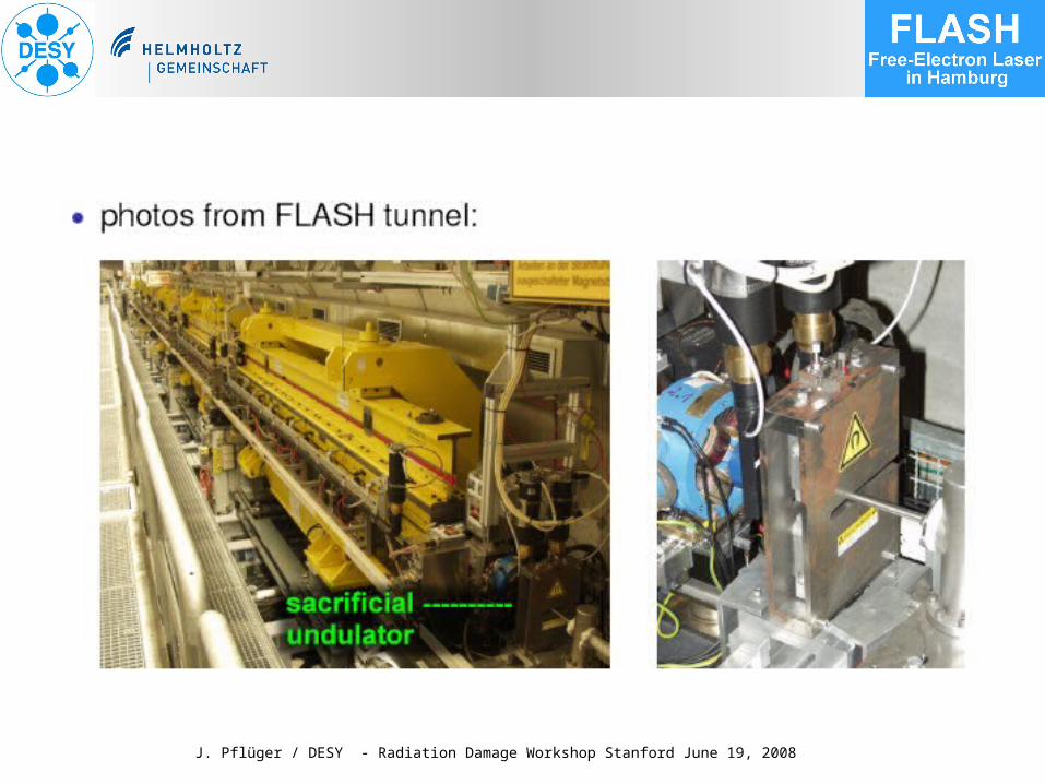
• The FLASH Diagnostic or “Sacrificial” Undulator
• Dose Measurements• Observed Demagnetization• TTF1 Results Revisited• FEL Damage Theory and Simulations • Life expectancy• Conclusions
J. Pflüger / DESY - Radiation Damage Workshop Stanford June 19, 2008
The Diagnostic Sacrificial Undulator
J. Pflüger / DESY - Radiation Damage Workshop Stanford June 19, 2008
J. Pflüger / DESY - Radiation Damage Workshop Stanford June 19, 2008
J. Pflüger / DESY - Radiation Damage Workshop Stanford June 19, 2008
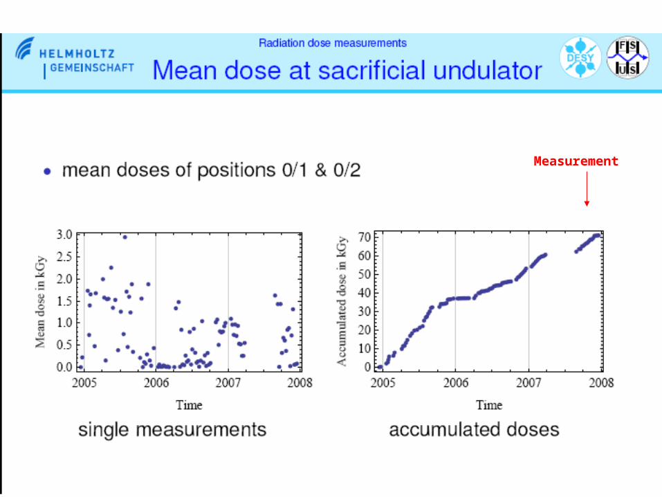
Radiation Dose Measurements
J. Pflüger / DESY - Radiation Damage Workshop Stanford June 19, 2008
12 / 2004 - 4 / 2008
Measurement
J. Pflüger / DESY - Radiation Damage Workshop Stanford June 19, 2008
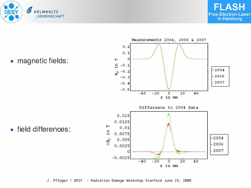
Demagnetization Measurements
J. Pflüger / DESY - Radiation Damage Workshop Stanford June 19, 2008
J. Pflüger / DESY - Radiation Damage Workshop Stanford June 19, 2008
J. Pflüger / DESY - Radiation Damage Workshop Stanford June 19, 2008
J. Pflüger / DESY - Radiation Damage Workshop Stanford June 19, 2008
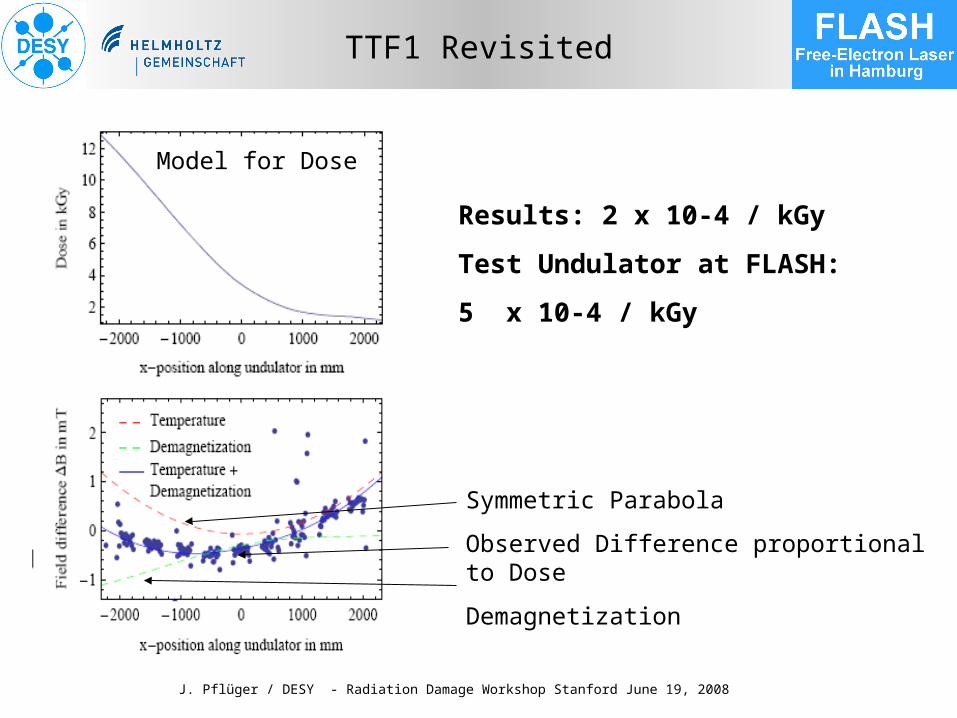
TTF1 Results (1999-2002) Revisited
J. Pflüger, B. Faatz, M. Tischer, T. Vielitz NIMA 507 (2003), 186,
J. Pflüger / DESY - Radiation Damage Workshop Stanford June 19, 2008
TTF1 Undulator System 1999-2002
1999 On Axis Collimator System
From: J. Pflüger, B. Faatz, M. Tischer, T. Vielitz NIMA 507 (2003), 186,
J. Pflüger / DESY - Radiation Damage Workshop Stanford June 19, 2008
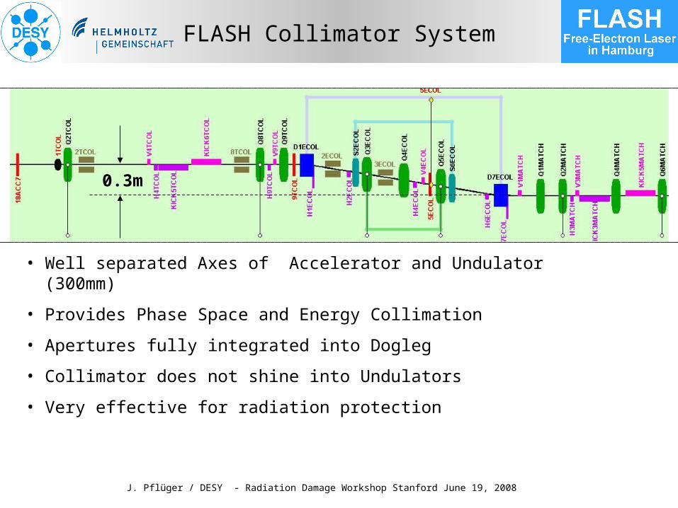
FLASH Collimator System
• Well separated Axes of Accelerator and Undulator (300mm)
• Provides Phase Space and Energy Collimation
• Apertures fully integrated into Dogleg
• Collimator does not shine into Undulators
• Very effective for radiation protection
0.3m
J. Pflüger / DESY - Radiation Damage Workshop Stanford June 19, 2008
•For the same phase shake (same power degradation), large error period means small error strength. Vice versa…• if the error period is small, large error strength (larger than ρ) is permitted
girder deformation• Remaining deformation is nearly sinusoidal, the error period δ equals to the support length• Deformation of 1.4429 2m AlMg Alloy 6-7m
Result:
=1.2mK/K= .0036 30m = 8.4°10% Power Degr.
J. Pflüger / DESY - Radiation Damage Workshop Stanford June 19, 2008
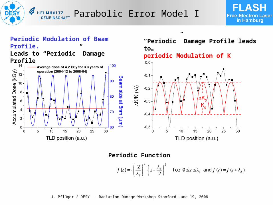
Parabolic Error Model I
)()( and 0for 2
2)(
22
zfzfzzzf
Periodic Function
Periodic Modulation of Beam Profile.Leads to “Periodic” Damage Profile
“Periodic” Damage Profile leads to…periodic Modulation of K
J. Pflüger / DESY - Radiation Damage Workshop Stanford June 19, 2008