JACKCON Electrolytic Capacitors CONTENTS OF QUALITY ASSURANCE
SCOPE ASSURANCE METHOD CONTENTS
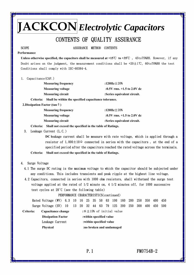
Performance Unless otherwise specified, the capacitors shall be measured at +15℃ to +35℃ , 45to75%RH. However, if any
Doubt arises on the judgment, the measurement conditions shall be +20±1℃, 60to70%RH the test
Conditions shall comply with IEC-60384-4.
1. Capacitance(CAP.)
Measuring frequency :120Hz±20%
Measuring voltage :0.5V rms. +1.5 to 2.0V dc Measuring circuit :Series equivalent circuit. Criteria: Shall be within the specified capacitance tolerance. 2.Dissipation Factor (tanδ) Measuring frequency :120Hz±20%
Measuring voltage :0.5V rms. +1.5 to 2.0V dc Measuring circuit :Series equivalent circuit. Criteria: Shall not exceed the specified in the table of Ratings. 3. Leakage Current (L.C.) DC leakage current shall be measure with rate voltage, which is applied through a
resistor of 1,000±10Ω connected in series with the capacitors , at the end of a
specified period after the capacitors reached the rated voltage across the terminals.
Criteria: Shall not exceed the specified in the table of Ratings.
4. Surge Voltage
4.1 The surge DC rating is the maximum voltage to which the capacitor should be subjected under
any conditions. This includes transients and peak ripple at the highest line voltage.
4.2 Capacitors, connected in series with 1000 ohm resistors, shall withstand the surge test
voltage applied at the rated of 1/2 minute on, 4 1/2 minutes off, for 1000 successive
1. Capacitors shall be placed in oven with application of ripple current and rate voltage for 2000±12hrs
at 105℃ 2. The capacitors should be use within
specified permissible ripple current in each standard products table(the sum of DC working voltage and AC peak voltage shall be equal to the rated DC working voltage
3. The specified maximum permissible ripple current in defined at 105℃
and 120 Hz 4. Then the capacitor shall be
subjected to standard atmospheric conditions for 16 hours, after witch measurements shall be made.
Physical no broken and undamaged
Capacitance
change Within ±20% of the initial value
TANδ Less then 200% of specified value
Leakage
Current
Within specified value
6. High temperature shelf life test
After 500hrs test at 105℃ without
rated working voltage. And then the capacitor shall be subjected to standard atmospheric conditions for 16 hours, after witch measurements shall be made. Physical no broken and undamaged
Capacitance
change Within ±10% of the initial value
TANδ Within specified value
Leakage
Current
Within specified value
7. Rotational temperature test
Capacitor is place in a oven whose temperature follow specific regulation to change. The specific regulations is “+25℃ (1 hr) → +105℃ (2 hrs) →
+25℃ (0.5 hr) → -25℃ (2 hrs) →
+25℃ (0.5 hr)”,and it called a
cycle. The test totals 10 cycles.
And then the capacitor shall be subjected to standard atmospheric conditions for 16 hours, after witch measurements shall be made.
Physical no broken and undamaged
Capacitance
change Within ±10% of the initial value
TANδ Less then 120% of specified value
Leakage
Current
Within specified value
8. Humidity test
Capacitors shall be exposed for 500±8hrs in an atmosphere of 90~ 95%R.Hat 40℃. And then the capacitor shall be subjected to standard atmospheric conditions for 16 hours, after witch measurements shall be made.
Physical no broken and undamaged
P.2 FM0754B-2
JACKCON Electrolytic Capacitors Capacitance
change Within ±10% of the initial value
TANδ Within specified value
Leakage
Current Within specified value
9. Low temperature test
Capacitor are place at -40±3℃ for 72±4hrs.And then the capacitor shall be subjected to standard atmospheric conditions for 16 hours, after witch measurements shall be made.
Physical no broken and undamaged
Capacitance change
Within ±10% of the initial value
TANδ Within specified value
Leakage Current
Within specified value
10. Vibration test
1. Fix it at the point 4mm or less form body. For ones of 12.5mm or 25mm or more length, use separate fixture.
2. Direction and during of vibration:3 orthogonal direction each for 2hrs total 6hrs.
3. Mutually frequency: 10 to55Hz reciprocation for 1 min.
4.Total amplitude:1.5mm
Physical no broken and undamaged
Capacitance
change Within ±10% of the initial value
TANδ Within specified value
Leakage
Current
Within specified value
11. Reflow test 1. IR Reflow
Temp (T1~T2) 100~150℃ Preheat Time (t1) max 40 sec Temp(T3) 260℃ Duration Time (t2) max 10 sec Temp(T4) 270℃ Peck Time (t3) max 5 sec
Reflow cycle
Twice or less
2. Solder bath method: Solder temperature:260±3℃ Immersion time:5+1/-0 sec Thickness of heat shunt (Printed wiring board):1.6mm 3. Soldering iron method: Bit temperature: 350±10℃ Application time of soldering
Iron:3+1/-0 sec
Physical no broken and undamaged
P.3 FM0754B-2
JACKCON Electrolytic Capacitors 12.
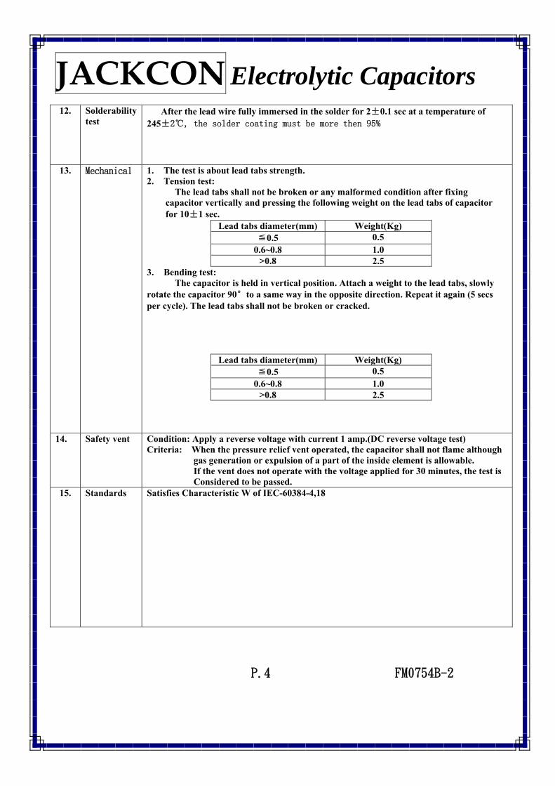
Solderability test
After the lead wire fully immersed in the solder for 2±0.1 sec at a temperature of 245±2℃, the solder coating must be more then 95%
13. Mechanical 1. The test is about lead tabs strength. 2. Tension test: The lead tabs shall not be broken or any malformed condition after fixing
capacitor vertically and pressing the following weight on the lead tabs of capacitor for 10±1 sec.
Lead tabs diameter(mm) Weight(Kg) ≦0.5 0.5
0.6~0.8 1.0 >0.8 2.5
3. Bending test: The capacitor is held in vertical position. Attach a weight to the lead tabs, slowly rotate the capacitor 90°to a same way in the opposite direction. Repeat it again (5 secs per cycle). The lead tabs shall not be broken or cracked.
Lead tabs diameter(mm) Weight(Kg) ≦0.5 0.5
0.6~0.8 1.0 >0.8 2.5
14. Safety vent
Condition: Apply a reverse voltage with current 1 amp.(DC reverse voltage test) Criteria: When the pressure relief vent operated, the capacitor shall not flame although
gas generation or expulsion of a part of the inside element is allowable. If the vent does not operate with the voltage applied for 30 minutes, the test is Considered to be passed.
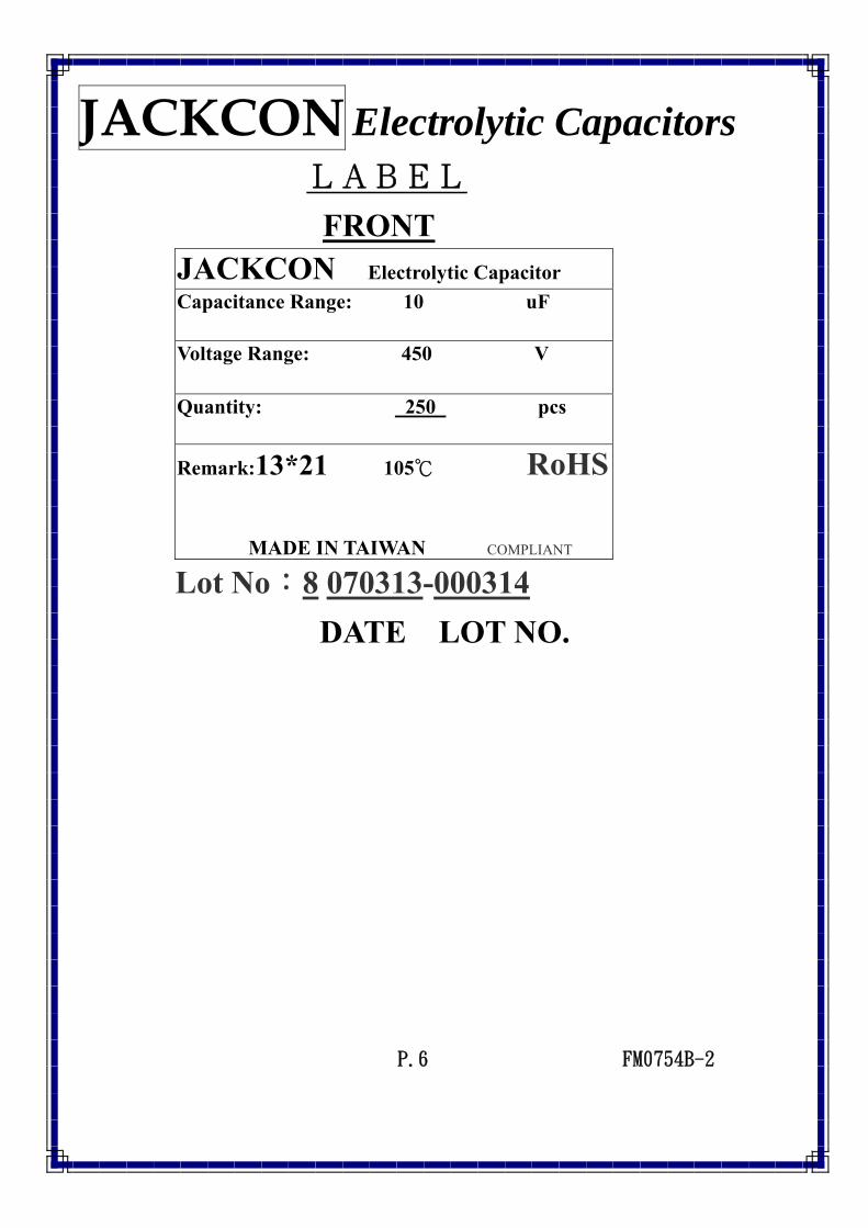
JACKCON Electrolytic Capacitor Capacitance Range: 10 uF Voltage Range: 450 V Quantity: 250 pcs
Remark:13*21 105℃ RoHS MADE IN TAIWAN COMPLIANT
Lot No:8 070313-000314 DATE LOT NO.
P.6 FM0754B-2
JACKCON Electrolytic Capacitors
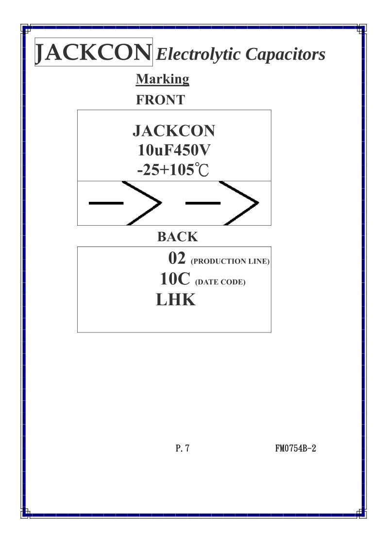
Marking FRONT
JACKCON 10uF450V -25+105℃
BACK 02 (PRODUCTION LINE)
10C (DATE CODE)
LHK
P.7 FM0754B-2
SGS Taiwan Ltd.台灣檢驗科技股份有限公司 Chemical-Taipei 33 WuChyuan Road, Wuku Industrial Zone, Taipei County, Taiwan /台北縣五股工業區五權路33號 t + 886 (02)2299 3279 f + 886 (02)2299 3237 www.sgs.com
Member of the SGS Group (SGS SA)
Unless otherwise stated the results shown in this test report refer only to the sample(s) tested. This test report cannot be reproduced, except in full, without prior written permission of the Company.除非另有說明,此報告結果僅對測試之樣品負責。本報告未經本公司書面許可,不可部分複製。This Test Report is issued by the Company under its General Conditions of Service printed overleaf or available on request and accessible at http://www.sgs.com/terms_and_conditions.htm. Attention is drawn to the limitation of liability, indemnification and jurisdiction issues defined therein. Any holder of this Test Report is advised that information contained hereon reflects the Company’s findings at the time of its intervention only and within the limits of Client’s instructions, if any. The Company’s sole responsibility is to its Client and this document does not exonerate parties to a transaction from exercising all their rights and obligations under the transaction documents. Any unauthorized alteration, forgery or falsification of the content or appearance of this document is unlawful and offenders may be prosecuted to the fullest extent of the law.
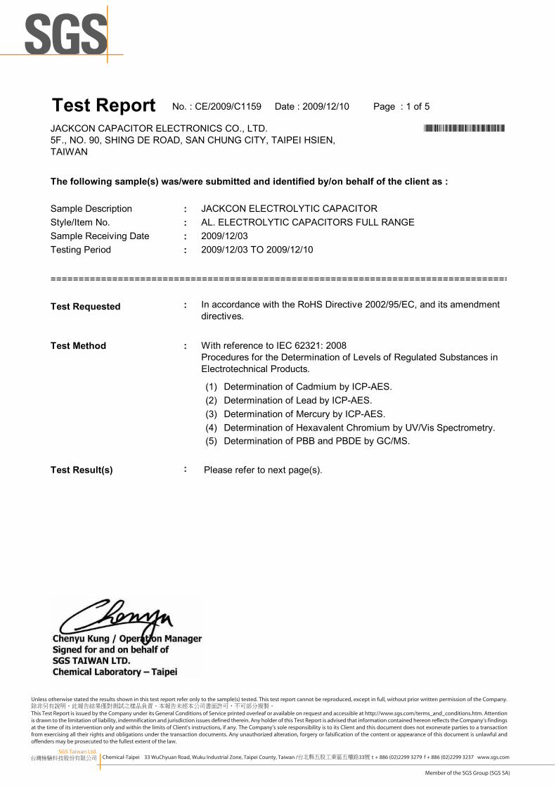
Sample Description :Style/Item No. :Sample Receiving Date :Testing Period :
In accordance with the RoHS Directive 2002/95/EC, and its amendmentdirectives.
The following sample(s) was/were submitted and identified by/on behalf of the client as :
With reference to IEC 62321: 2008Procedures for the Determination of Levels of Regulated Substances inElectrotechnical Products.
Determination of Cadmium by ICP-AES.
Please refer to next page(s).
Determination of Lead by ICP-AES.Determination of Mercury by ICP-AES.Determination of Hexavalent Chromium by UV/Vis Spectrometry.Determination of PBB and PBDE by GC/MS.
Test Report
2009/12/03
JACKCON ELECTROLYTIC CAPACITOR
*CE/2009/C1159*
No. : CE/2009/C1159 Date : 2009/12/10 Page : 1 of 5
JACKCON CAPACITOR ELECTRONICS CO., LTD.5F., NO. 90, SHING DE ROAD, SAN CHUNG CITY, TAIPEI HSIEN,TAIWAN
SGS Taiwan Ltd.台灣檢驗科技股份有限公司 Chemical-Taipei 33 WuChyuan Road, Wuku Industrial Zone, Taipei County, Taiwan /台北縣五股工業區五權路33號 t + 886 (02)2299 3279 f + 886 (02)2299 3237 www.sgs.com
Member of the SGS Group (SGS SA)
Unless otherwise stated the results shown in this test report refer only to the sample(s) tested. This test report cannot be reproduced, except in full, without prior written permission of the Company.除非另有說明,此報告結果僅對測試之樣品負責。本報告未經本公司書面許可,不可部分複製。This Test Report is issued by the Company under its General Conditions of Service printed overleaf or available on request and accessible at http://www.sgs.com/terms_and_conditions.htm. Attention is drawn to the limitation of liability, indemnification and jurisdiction issues defined therein. Any holder of this Test Report is advised that information contained hereon reflects the Company’s findings at the time of its intervention only and within the limits of Client’s instructions, if any. The Company’s sole responsibility is to its Client and this document does not exonerate parties to a transaction from exercising all their rights and obligations under the transaction documents. Any unauthorized alteration, forgery or falsification of the content or appearance of this document is unlawful and offenders may be prosecuted to the fullest extent of the law.
5F., NO. 90, SHING DE ROAD, SAN CHUNG CITY, TAIPEI HSIEN,TAIWAN
5. The sample(s) was/were analyzed on behalf of the applicant as mixing sample in one testing.The above result(s) was/were only given as the informality value.
3. MDL = Method Detection Limit
SGS Taiwan Ltd.台灣檢驗科技股份有限公司 Chemical-Taipei 33 WuChyuan Road, Wuku Industrial Zone, Taipei County, Taiwan /台北縣五股工業區五權路33號 t + 886 (02)2299 3279 f + 886 (02)2299 3237 www.sgs.com
Member of the SGS Group (SGS SA)
Unless otherwise stated the results shown in this test report refer only to the sample(s) tested. This test report cannot be reproduced, except in full, without prior written permission of the Company.除非另有說明,此報告結果僅對測試之樣品負責。本報告未經本公司書面許可,不可部分複製。This Test Report is issued by the Company under its General Conditions of Service printed overleaf or available on request and accessible at http://www.sgs.com/terms_and_conditions.htm. Attention is drawn to the limitation of liability, indemnification and jurisdiction issues defined therein. Any holder of this Test Report is advised that information contained hereon reflects the Company’s findings at the time of its intervention only and within the limits of Client’s instructions, if any. The Company’s sole responsibility is to its Client and this document does not exonerate parties to a transaction from exercising all their rights and obligations under the transaction documents. Any unauthorized alteration, forgery or falsification of the content or appearance of this document is unlawful and offenders may be prosecuted to the fullest extent of the law.
*CE/2009/C1159*
Test Report No. : CE/2009/C1159 Date : 2009/12/10 Page : 3 of 5
JACKCON CAPACITOR ELECTRONICS CO., LTD.5F., NO. 90, SHING DE ROAD, SAN CHUNG CITY, TAIPEI HSIEN,TAIWAN
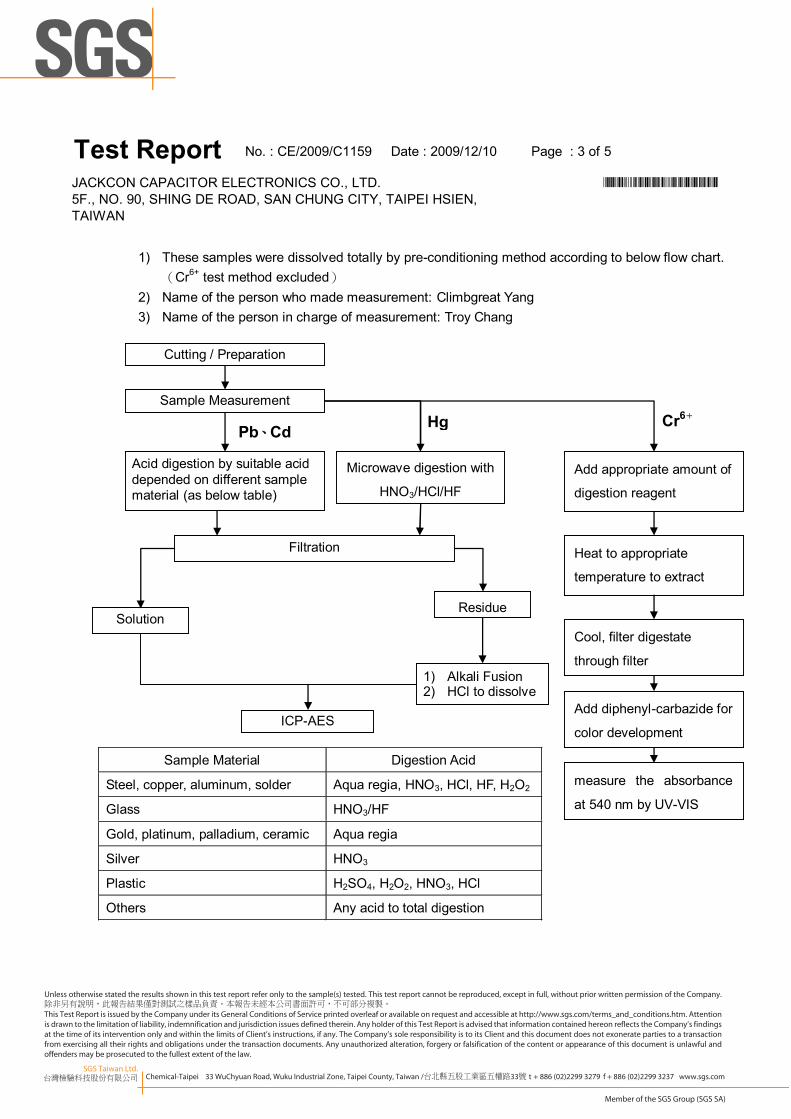
1) These samples were dissolved totally by pre-conditioning method according to below flow chart.(Cr6+ test method excluded)
2) Name of the person who made measurement: Climbgreat Yang3) Name of the person in charge of measurement: Troy Chang
Cr6+
Sample Material Digestion Acid
Steel, copper, aluminum, solder Aqua regia, HNO3, HCl, HF, H2O2
Glass HNO3/HF
Gold, platinum, palladium, ceramic Aqua regia
Silver HNO3
Plastic H2SO4, H2O2, HNO3, HCl
Others Any acid to total digestion
Pb、Cd
Solution
ICP-AES
Acid digestion by suitable aciddepended on different samplematerial (as below table)
Filtration
Residue
1) Alkali Fusion2) HCl to dissolve
Sample Measurement
Cutting / Preparation
Microwave digestion with
HNO3/HCl/HF
Heat to appropriate
temperature to extract
Cool, filter digestate
through filter
Add diphenyl-carbazide for
color development
measure the absorbance
at 540 nm by UV-VIS
Add appropriate amount of
digestion reagent
Hg
SGS Taiwan Ltd.台灣檢驗科技股份有限公司 Chemical-Taipei 33 WuChyuan Road, Wuku Industrial Zone, Taipei County, Taiwan /台北縣五股工業區五權路33號 t + 886 (02)2299 3279 f + 886 (02)2299 3237 www.sgs.com
Member of the SGS Group (SGS SA)
Unless otherwise stated the results shown in this test report refer only to the sample(s) tested. This test report cannot be reproduced, except in full, without prior written permission of the Company.除非另有說明,此報告結果僅對測試之樣品負責。本報告未經本公司書面許可,不可部分複製。This Test Report is issued by the Company under its General Conditions of Service printed overleaf or available on request and accessible at http://www.sgs.com/terms_and_conditions.htm. Attention is drawn to the limitation of liability, indemnification and jurisdiction issues defined therein. Any holder of this Test Report is advised that information contained hereon reflects the Company’s findings at the time of its intervention only and within the limits of Client’s instructions, if any. The Company’s sole responsibility is to its Client and this document does not exonerate parties to a transaction from exercising all their rights and obligations under the transaction documents. Any unauthorized alteration, forgery or falsification of the content or appearance of this document is unlawful and offenders may be prosecuted to the fullest extent of the law.
JACKCON CAPACITOR ELECTRONICS CO., LTD. *CE/2009/C1159*5F., NO. 90, SHING DE ROAD, SAN CHUNG CITY, TAIPEI HSIEN,TAIWAN
Test Report No. : CE/2009/C1159 Date : 2009/12/10 Page : 4 of 5
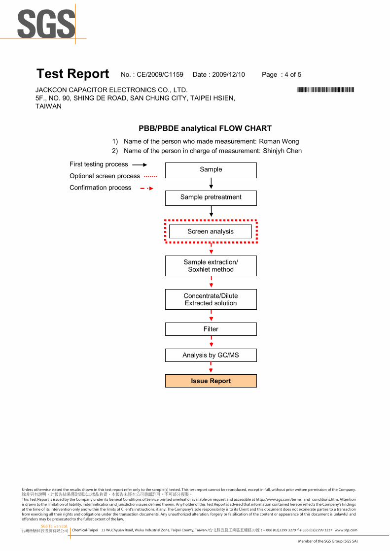
PBB/PBDE analytical FLOW CHART
First testing process
Optional screen process
Confirmation process
Sample
Screen analysis
Issue Report
Sample pretreatment
Sample extraction/Soxhlet method
Concentrate/DiluteExtracted solution
Analysis by GC/MS
Filter
1) Name of the person who made measurement: Roman Wong2) Name of the person in charge of measurement: Shinjyh Chen
SGS Taiwan Ltd.台灣檢驗科技股份有限公司 Chemical-Taipei 33 WuChyuan Road, Wuku Industrial Zone, Taipei County, Taiwan /台北縣五股工業區五權路33號 t + 886 (02)2299 3279 f + 886 (02)2299 3237 www.sgs.com
Member of the SGS Group (SGS SA)
Unless otherwise stated the results shown in this test report refer only to the sample(s) tested. This test report cannot be reproduced, except in full, without prior written permission of the Company.除非另有說明,此報告結果僅對測試之樣品負責。本報告未經本公司書面許可,不可部分複製。This Test Report is issued by the Company under its General Conditions of Service printed overleaf or available on request and accessible at http://www.sgs.com/terms_and_conditions.htm. Attention is drawn to the limitation of liability, indemnification and jurisdiction issues defined therein. Any holder of this Test Report is advised that information contained hereon reflects the Company’s findings at the time of its intervention only and within the limits of Client’s instructions, if any. The Company’s sole responsibility is to its Client and this document does not exonerate parties to a transaction from exercising all their rights and obligations under the transaction documents. Any unauthorized alteration, forgery or falsification of the content or appearance of this document is unlawful and offenders may be prosecuted to the fullest extent of the law.
** End of Report **
JACKCON CAPACITOR ELECTRONICS CO., LTD. *CE/2009/C1159*5F., NO. 90, SHING DE ROAD, SAN CHUNG CITY, TAIPEI HSIEN,TAIWAN
Test Report No. : CE/2009/C1159 Date : 2009/12/10 Page : 5 of 5