236
| Date post: | 20-Aug-2018 |
| Category: |
Documents |
| Upload: | nguyennhan |
| View: | 224 times |
| Download: | 0 times |

�
��������������
�� �� ������
�������������� ���
�

In this manual we have tried as much as possible to describe all thevarious matters.However, we cannot describe all the matters which must not be done,or which cannot be done, because there are so many possibilities.Therefore, matters which are not especially described as possible inthis manual should be regarded as ”impossible”.
The export of this product is subject to the authorization of thegovernment of the country from where the product is exported.
� No part of this manual may be reproduced in any form.
� All specifications and designs are subject to change without notice.

B–64160EN/01 PREFACE
p–1
�������
The mode covered by this manual, and their abbreviations are :
Product Name Abbreviations
FANUC Series 0i–PC 0i–PC Series 0i–C 0i
NOTESome functions described in this manual may not be appliedto some products. For details, refer to the DESCRIPTIONS (B–64112EN).

B–64160EN/01PREFACE
p–2
The following table lists the manuals related to Series 0i–PC. This manual is indicated by an asterisk(*).
Manual name Specificationnumber
FANUC Series 0i–MODEL C/0i Mate–MODEL C DESCRIPTIONS
B–64112EN
FANUC Series 0i–MODEL C/0i Mate–MODEL CCONNECTION MANUAL (HARDWARE)
B–64113EN
FANUC Series 0i–MODEL C/0i Mate–MODEL CCONNECTION MANUAL (FUNCTION)
B–64113EN–1
FANUC Series 0i–PC CONNECTION MANUAL (FUNCTION)
B–64153EN
FANUC Series 0i–PC OPERATOR’S MANUAL B–64154EN
FANUC Series 0i–MODEL C/0i Mate–MODEL CMAINTENANCE MANUAL
B–64115EN
FANUC Series 0i–PC PARAMETER MANUAL B–64160EN *
PROGRAMMING MANUAL
Macro Compiler/Macro Executor PROGRAMMING MANUAL
B–61803E–1
FAPT MACRO COMPILER (For Personal Computer)PROGRAMMING MANUAL
B–66102E
PMC
PMC Ladder Language PROGRAMMING MANUAL B–61863E
Network
Profibus–DP Board OPERATOR’S MANUAL B–62924EN
FAST Ethernet Board/FAST DATA SERVER OPERATOR’S MANUAL
B–63644EN
Ethernet Board/DATA SERVER Board OPERATOR’S MANUAL
B–63354EN
DeviceNet Board OPERATOR’S MANUAL B–63404EN
Open CNC
FANUC OPEN CNC Basic Operation Package 1 (For Windows95/NT) OPERATOR’S MANUAL
B–62994EN
FANUC OPEN CNC (DNC Operation Management Package) OPERATOR’S MANUAL
B–63214EN
Related manuals ofSeries 0i–PC

B–64160EN/01 PREFACE
p–3
The following table lists the manuals related to SERVO MOTOR �is/�i series.
Manual name Specificationnumber
FANUC AC SERVO MOTOR �is series FANUC AC SERVO MOTOR �i series DESCRIPTIONS
B–65262EN
FANUC AC SERVO MOTOR �is series FANUC AC SERVO MOTOR �i series PARAMETER MANUAL
B–65270EN
FANUC AC SPINDLE MOTOR �i series DESCRIPTIONS B–65272EN
FANUC AC SPINDLE MOTOR �i series PARAMETER MANUAL
B–65280EN
FANUC SERVO AMPLIFIER �i series DESCRIPTIONS B–65282EN
FANUC AC SERVO MOTOR �is series FANUC AC SERVO MOTOR �i series FANUC AC SPINDLE MOTOR �i seriesFANUC SERVO AMPLIFIER �i seriesMAINTENANCE MANUAL
B–65285EN
The following table lists the manuals related to Servo Motor β series.
Manual name Specificationnumber
FANUC SERVO MOTOR β series DESCRIPTIONS B–65232EN
FANUC SERVO MOTOR β series MAINTENANCE MANUAL
B–65235EN
FANUC SERVO MOTOR β series(I/O Link Option)DESCRIPTIONS
B–65245EN
Related manuals ofSERVO MOTOR �is/�i series
Related manuals ofServo Motor β series

B–64160EN/01 Table of Contents
c–1
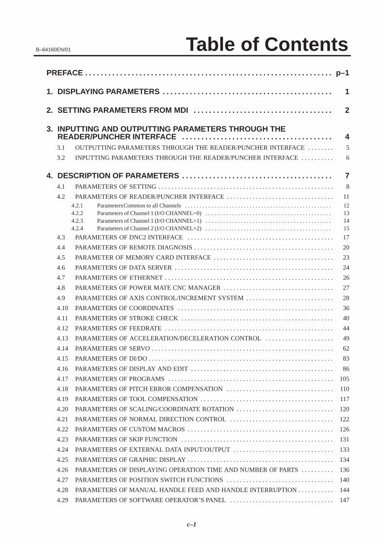
PREFACE p–1. . . . . . . . . . . . . . . . . . . . . . . . . . . . . . . . . . . . . . . . . . . . . . . . . . . . . . . . . . . . . . . .
1. DISPLAYING PARAMETERS 1. . . . . . . . . . . . . . . . . . . . . . . . . . . . . . . . . . . . . . . . . . . .
2. SETTING PARAMETERS FROM MDI 2. . . . . . . . . . . . . . . . . . . . . . . . . . . . . . . . . . . .
3. INPUTTING AND OUTPUTTING PARAMETERS THROUGH THE READER/PUNCHER INTERFACE 4. . . . . . . . . . . . . . . . . . . . . . . . . . . . . . . . . . . . . . . 3.1 OUTPUTTING PARAMETERS THROUGH THE READER/PUNCHER INTERFACE 5. . . . . . . .
3.2 INPUTTING PARAMETERS THROUGH THE READER/PUNCHER INTERFACE 6. . . . . . . . . .
4. DESCRIPTION OF PARAMETERS 7. . . . . . . . . . . . . . . . . . . . . . . . . . . . . . . . . . . . . . . 4.1 PARAMETERS OF SETTING 8. . . . . . . . . . . . . . . . . . . . . . . . . . . . . . . . . . . . . . . . . . . . . . . . . . . . . .
4.2 PARAMETERS OF READER/PUNCHER INTERFACE 11. . . . . . . . . . . . . . . . . . . . . . . . . . . . . . . . . 4.2.1 Parameters Common to all Channels 12. . . . . . . . . . . . . . . . . . . . . . . . . . . . . . . . . . . . . . . . . . . . . . . . . . 4.2.2 Parameters of Channel 1 (I/O CHANNEL=0) 13. . . . . . . . . . . . . . . . . . . . . . . . . . . . . . . . . . . . . . . . . . . 4.2.3 Parameters of Channel 1 (I/O CHANNEL=1) 14. . . . . . . . . . . . . . . . . . . . . . . . . . . . . . . . . . . . . . . . . . . 4.2.4 Parameters of Channel 2 (I/O CHANNEL=2) 15. . . . . . . . . . . . . . . . . . . . . . . . . . . . . . . . . . . . . . . . . . .
4.3 PARAMETERS OF DNC2 INTERFACE 17. . . . . . . . . . . . . . . . . . . . . . . . . . . . . . . . . . . . . . . . . . . . .
4.4 PARAMETERS OF REMOTE DIAGNOSIS 20. . . . . . . . . . . . . . . . . . . . . . . . . . . . . . . . . . . . . . . . . . .
4.5 PARAMETER OF MEMORY CARD INTERFACE 23. . . . . . . . . . . . . . . . . . . . . . . . . . . . . . . . . . . . .
4.6 PARAMETERS OF DATA SERVER 24. . . . . . . . . . . . . . . . . . . . . . . . . . . . . . . . . . . . . . . . . . . . . . . . .
4.7 PARAMETERS OF ETHERNET 26. . . . . . . . . . . . . . . . . . . . . . . . . . . . . . . . . . . . . . . . . . . . . . . . . . . .
4.8 PARAMETERS OF POWER MATE CNC MANAGER 27. . . . . . . . . . . . . . . . . . . . . . . . . . . . . . . . . .
4.9 PARAMETERS OF AXIS CONTROL/INCREMENT SYSTEM 28. . . . . . . . . . . . . . . . . . . . . . . . . . .
4.10 PARAMETERS OF COORDINATES 36. . . . . . . . . . . . . . . . . . . . . . . . . . . . . . . . . . . . . . . . . . . . . . . .
4.11 PARAMETERS OF STROKE CHECK 40. . . . . . . . . . . . . . . . . . . . . . . . . . . . . . . . . . . . . . . . . . . . . . .
4.12 PARAMETERS OF FEEDRATE 44. . . . . . . . . . . . . . . . . . . . . . . . . . . . . . . . . . . . . . . . . . . . . . . . . . . .
4.13 PARAMETERS OF ACCELERATION/DECELERATION CONTROL 49. . . . . . . . . . . . . . . . . . . . .
4.14 PARAMETERS OF SERVO 62. . . . . . . . . . . . . . . . . . . . . . . . . . . . . . . . . . . . . . . . . . . . . . . . . . . . . . . .
4.15 PARAMETERS OF DI/DO 83. . . . . . . . . . . . . . . . . . . . . . . . . . . . . . . . . . . . . . . . . . . . . . . . . . . . . . . . .
4.16 PARAMETERS OF DISPLAY AND EDIT 86. . . . . . . . . . . . . . . . . . . . . . . . . . . . . . . . . . . . . . . . . . . .
4.17 PARAMETERS OF PROGRAMS 105. . . . . . . . . . . . . . . . . . . . . . . . . . . . . . . . . . . . . . . . . . . . . . . . . . .
4.18 PARAMETERS OF PITCH ERROR COMPENSATION 110. . . . . . . . . . . . . . . . . . . . . . . . . . . . . . . . .
4.19 PARAMETERS OF TOOL COMPENSATION 117. . . . . . . . . . . . . . . . . . . . . . . . . . . . . . . . . . . . . . . . .
4.20 PARAMETERS OF SCALING/COORDINATE ROTATION 120. . . . . . . . . . . . . . . . . . . . . . . . . . . . . .
4.21 PARAMETERS OF NORMAL DIRECTION CONTROL 122. . . . . . . . . . . . . . . . . . . . . . . . . . . . . . . .
4.22 PARAMETERS OF CUSTOM MACROS 126. . . . . . . . . . . . . . . . . . . . . . . . . . . . . . . . . . . . . . . . . . . . .
4.23 PARAMETERS OF SKIP FUNCTION 131. . . . . . . . . . . . . . . . . . . . . . . . . . . . . . . . . . . . . . . . . . . . . . .
4.24 PARAMETERS OF EXTERNAL DATA INPUT/OUTPUT 133. . . . . . . . . . . . . . . . . . . . . . . . . . . . . . .
4.25 PARAMETERS OF GRAPHIC DISPLAY 134. . . . . . . . . . . . . . . . . . . . . . . . . . . . . . . . . . . . . . . . . . . . .
4.26 PARAMETERS OF DISPLAYING OPERATION TIME AND NUMBER OF PARTS 136. . . . . . . . . .
4.27 PARAMETERS OF POSITION SWITCH FUNCTIONS 140. . . . . . . . . . . . . . . . . . . . . . . . . . . . . . . . .
4.28 PARAMETERS OF MANUAL HANDLE FEED AND HANDLE INTERRUPTION 144. . . . . . . . . . .
4.29 PARAMETERS OF SOFTWARE OPERATOR’S PANEL 147. . . . . . . . . . . . . . . . . . . . . . . . . . . . . . . .

B–64160EN/01Table of Contents
c–2
4.30 PARAMETERS OF AXIS CONTROL BY PMC 150. . . . . . . . . . . . . . . . . . . . . . . . . . . . . . . . . . . . . . .
4.31 PARAMETERS OF SIMPLE SYNCHRONOUS CONTROL 155. . . . . . . . . . . . . . . . . . . . . . . . . . . . . .
4.32 PARAMETERS OF SEQUENCE NUMBER COMPARISON AND STOP 162. . . . . . . . . . . . . . . . . . .
4.33 PARAMETERS OF FS0i BASIC FUNCTIONS 163. . . . . . . . . . . . . . . . . . . . . . . . . . . . . . . . . . . . . . . .
4.34 OTHER PARAMETERS 165. . . . . . . . . . . . . . . . . . . . . . . . . . . . . . . . . . . . . . . . . . . . . . . . . . . . . . . . . .
4.35 PARAMETERS OF MAINTENANCE 169. . . . . . . . . . . . . . . . . . . . . . . . . . . . . . . . . . . . . . . . . . . . . . .
4.36 PARAMETERS OF OPERATION HISTORY 170. . . . . . . . . . . . . . . . . . . . . . . . . . . . . . . . . . . . . . . . . .
4.37 PARAMETERS OF THE PRESS FUNCTION 174. . . . . . . . . . . . . . . . . . . . . . . . . . . . . . . . . . . . . . . . .
4.38 PARAMETERS FOR THE SPEED AND LOOP GAIN SWITCH 185. . . . . . . . . . . . . . . . . . . . . . . . . .
4.39 PARAMETERS FOR THE NIBBLING FUNCTION 195. . . . . . . . . . . . . . . . . . . . . . . . . . . . . . . . . . . .
4.40 PARAMETERS FOR THE PATTERN FUNCTION 198. . . . . . . . . . . . . . . . . . . . . . . . . . . . . . . . . . . . .
4.41 PARAMETERS FOR THE TURRET AXIS 203. . . . . . . . . . . . . . . . . . . . . . . . . . . . . . . . . . . . . . . . . . .
4.42 PARAMETERS FOR C–AXIS CONTROL 207. . . . . . . . . . . . . . . . . . . . . . . . . . . . . . . . . . . . . . . . . . . .
4.43 PARAMETERS FOR THE SAFETY ZONE 213. . . . . . . . . . . . . . . . . . . . . . . . . . . . . . . . . . . . . . . . . . .
4.44 ADDITIONAL PARAMETERS FOR DI/DO SIGNALS 219. . . . . . . . . . . . . . . . . . . . . . . . . . . . . . . . .
APPENDIX
A. CHARACTER CODE LIST 223. . . . . . . . . . . . . . . . . . . . . . . . . . . . . . . . . . . . . . . . . . . . . .

B–64160EN/01 1. DISPLAYING PARAMETERS
1
1 DISPLAYING PARAMETERS
Follow the procedure below to display parameters.
(1) Press the SYSTEM function key on the MDI as many times as required,
or alternatively, press the SYSTEM function key once, then the PARAM
section display soft key. The parameter screen is then selected.
PARAMETER (FEEDRATE) O0001 N12345
1401 RDR JZR RF0 LRP RPD0 0 0 0 0 0 0 0
1402 DLF HFC0 0 0 0 0 0 0 0
1410 DRY RUN FEEDRATE 100001411 INIT.CUTTING F 01420 RAPID FEEDRATE X 15000
Y 15000 Z 15000
> MEM STRT MTN FIN *** 10:02:35[PARAM] [DGNOS] [ PMC ] [SYSTEM] [(OPRT)]
Cursor
Soft key display(section select)
��� PROGOFFSETSETTING CUSTOM
SYSTEM MESSAGE GRAPH
Function key
Return menu key Soft key Continuous menu key
(2) The parameter screen consists of multiple pages. Use step (a) or (b)to display the page that contains the parameter you want to display.
(a) Use the page select key or the cursor move keys to display the de-sired page.
(b) Enter the data number of the parameter you want to display fromthe keyboard, then press the [NO.SRH] soft key. The parameterpage containing the specified data number appears with the cur-sor positioned at the data number. (The data is displayed in re-verse video.)
NOTEIf key entry is started with the section select soft keysdisplayed, they are replaced automatically by operationselect soft keys including [NO.SRH]. Pressing the [(OPRT)]soft key can also cause the operation select keys to bedisplayed.
> MEM STRT MTN FIN *** 10:02:34[NO.SRH] [ ON:1 ] [ OFF:0 ] [+INPUT] [INPUT ] ← Soft key display
(section select)
← Data entered fromthe keyboard

B–64160EN/012. SETTING PARAMETERS FROM MDI
2
2 SETTING PARAMETERS FROM MDI
Follow the procedure below to set parameters.
(1) Place the NC in the MDI mode or the emergency stop state.
(2) Follow the substeps below to enable writing of parameters.
1. To display the setting screen, press the OFFSETSETTING function key as
many times as required, or alternatively press the OFFSETSETTING function
key once, then the [SETTING] section select soft key. The firstpage of the setting screen appears.
2. Position the cursor on “PARAMETER WRITE” using the cursormove keys.
SETTING (HANDY) O0001 N00010
PARAMETER WRITE = (0:DISABLE 1:ENABLE)TV CHECK = 0 (0:OFF 1:ON)PUNCH CODE = 0 (0:EIA 1:ISO)INPUT UNIT = 0 (0:MM 1:INCH)I/O CHANNEL = 0 (0–3:CHANNEL NO.)
0
3. Press the [(OPRT)] soft key to display operation select soft keys.
> MDI STOP *** *** *** 10:03:02[NO.SRH] [ ON:1 ] [ OFF:0 ] [+INPUT] [INPUT]
← Soft key display(section select)
4. To set “PARAMETER WRITE=” to 1, press the ON:1 soft key,or alternatively enter 1 and press the INPUT soft key. From nowon, the parameters can be set. At the same time an alarm condi-tion (P/S100 PARAMETER WRITE ENABLE) occurs in theCNC.
(3) To display the parameter screen, press the SYSTEM function key as many
times as required, or alternatively press the SYSTEM function key once,
then the PARAM section select soft key.(See “1. Displaying Parameters.”)
(4) Display the page containing the parameter you want to set, and positionthe cursor on the parameter. (See “1. Displaying Parameters.”)
(5) Enter data, then press the [INPUT] soft key. The parameter indicatedby the cursor is set to the entered data.

B–64160EN/01 2. SETTING PARAMETERS FROM MDI
3
[Example] 12000 [INPUT]
PARAMETER (FEEDRATE) O0001 N00010
1401 RDR JZR RPD0 0 0 0 0 0 0 0
1402 JRV0 0 0 0 0 0 0 0
1410 DRY RUN FEEDRATE1412 01420 RAPID FEEDRATEX 15000
Y 15000Z 15000
12000
> MDI STOP *** *** ALM 10:03:10[NO.SRH] [ ON:1 ] [ OFF:0 ] [+INPUT] [INPUT]
Cursor
Data can be entered continuously for parameters, starting at the selectedparameter, by separating each data item with a semicolon (;).
[Example] Entering 10;20;30;40 and pressing the INPUT key assigns values 10, 20,30, and 40 to parameters in order starting at the parameter indicatedby thecursor.
(6) Repeat steps (4) and (5) as required.
(7) If parameter setting is complete, set “PARAMETER WRITE=” to 0on the setting screen to disable further parameter setting.
(8) Reset the NC to release the alarm condition (P/S100).If an alarm condition (P/S000 PLEASE TURN OFF POWER) occursin the NC, turn it off before continuing operation.

B–64160EN/013. INPUTTING AND OUTPUTTING PARAMETERS THROUGH
THE READER/PUNCHER INTERFACE
4
3INPUTTING AND OUTPUTTING PARAMETERS THROUGH THEREADER/PUNCHER INTERFACE
This section explains the parameter input/output procedures forinput/output devices connected to the reader/puncher interface.The following description assumes the input/output devices are ready forinput/output. It also assumes parameters peculiar to the input/outputdevices, such as the baud rate and the number of stop bits, have been setin advance. (See Section 4.2)

B–64160EN/013. INPUTTING AND OUTPUTTING PARAMETERS THROUGH
THE READER/PUNCHER INTERFACE
5
(1) Select the EDIT mode or set to Emergency stop.
(2) To select the parameter screen, press the SYSTEM function key as many
times as required, or alternatively press the SYSTEM function key once,
then the [PARAM] section select soft key.
(3) Press the [(OPRT)] soft key to display operation select soft keys, thenpress the forward menu key located at the right–hand side of the softkeys to display another set of operation select keys including[PUNCH].
PARAMETER (FEEDRATE) O0001 N00010
1401 RDR JZR RPD0 0 0 0 0 0 0 0
1402 JRV0 0 0 0 0 0 0 0
1410 DRY RUN FEEDRATE1412 01420 RAPID FEEDRATEX 15000
Y 15000Z 15000
12000
> MDI STOP *** *** ALM 10:03:10 [NO.SRH] [ON:1] [OFF:0] [+INPUT] [INPUT]
Cursor
State displaySoft key display (operation select)
(4) Pressing the [PUNCH] soft key changes the soft key display asshown below:
> EDIT STOP *** *** *** 10:35:03[ ] [ ] [ ] [CANCEL] [ EXEC ]
(5) Press the [EXEC] soft key to start parameter output. Whenparameters are being output, “OUTPUT” blinks in the state displayfield on the lower part of the screen.
> EDIT STOP *** *** *** 10:35:04 OUTPUT[ ] [ ] [ ] [CANCEL] [ EXEC ]
← OUTPUT blinking
(6) When parameter output terminates, “OUTPUT” stops blinking. Press
the RESET key to interrupt parameter output.
3.1OUTPUTTINGPARAMETERSTHROUGH THEREADER/PUNCHERINTERFACE
B–64160EN/013. INPUTTING AND OUTPUTTING PARAMETERS THROUGH
THE READER/PUNCHER INTERFACE
6
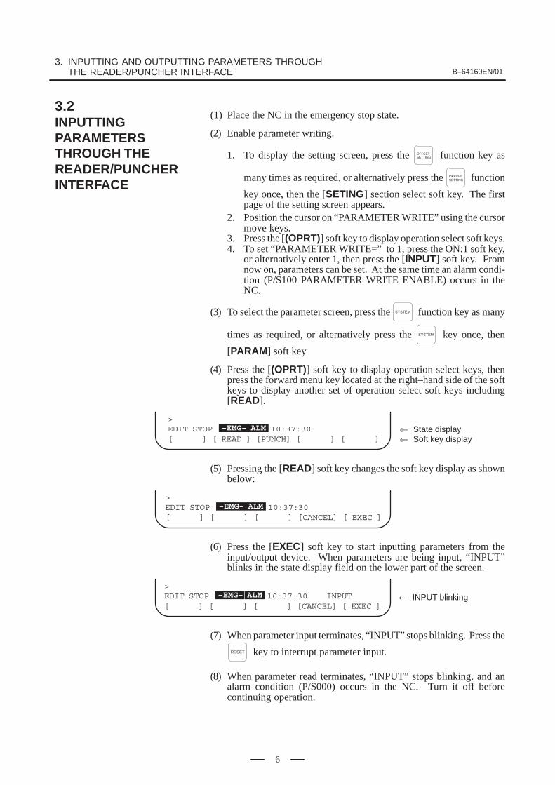
(1) Place the NC in the emergency stop state.
(2) Enable parameter writing.
1. To display the setting screen, press the OFFSETSETTING function key as
many times as required, or alternatively press the OFFSETSETTING function
key once, then the [SETING] section select soft key. The firstpage of the setting screen appears.
2. Position the cursor on “PARAMETER WRITE” using the cursormove keys.
3. Press the [(OPRT)] soft key to display operation select soft keys.4. To set “PARAMETER WRITE=” to 1, press the ON:1 soft key,
or alternatively enter 1, then press the [INPUT] soft key. Fromnow on, parameters can be set. At the same time an alarm condi-tion (P/S100 PARAMETER WRITE ENABLE) occurs in theNC.
(3) To select the parameter screen, press the SYSTEM function key as many
times as required, or alternatively press the SYSTEM key once, then
[PARAM] soft key.
(4) Press the [(OPRT)] soft key to display operation select keys, thenpress the forward menu key located at the right–hand side of the softkeys to display another set of operation select soft keys including[READ].
> EDIT STOP ALM 10:37:30[ ] [ READ ] [PUNCH] [ ] [ ]
–EMG– ALM
← Soft key display← State display
(5) Pressing the [READ] soft key changes the soft key display as shownbelow:
> EDIT STOP ALM 10:37:30[ ] [ ] [ ] [CANCEL] [ EXEC ]
–EMG– ALM
(6) Press the [EXEC] soft key to start inputting parameters from theinput/output device. When parameters are being input, “INPUT”blinks in the state display field on the lower part of the screen.
> EDIT STOP ALM 10:37:30 INPUT[ ] [ ] [ ] [CANCEL] [ EXEC ]
–EMG– ALM ← INPUT blinking
(7) When parameter input terminates, “INPUT” stops blinking. Press the
RESET key to interrupt parameter input.
(8) When parameter read terminates, “INPUT” stops blinking, and analarm condition (P/S000) occurs in the NC. Turn it off beforecontinuing operation.
3.2INPUTTINGPARAMETERSTHROUGH THE READER/PUNCHERINTERFACE

B–64160EN/01 4. DESCRIPTION OF PARAMETERS
7
4 DESCRIPTION OF PARAMETERS
Parameters are classified by data type as follows:
Table 4 Data Types and Valid Data Ranges of Parameters
Data type Valid data range Remarks
Bit0 or 1
Bit axis0 or 1
Byte –128 to 127 0 to 255
In some parameters, signs areignored.Byte axis
–128 to 127 0 to 255
In some parameters, signs areignored.
Word –32768 to 32767 0 to 65535
In some parameters, signs areignored.Word axis
–32768 to 32767 0 to 65535
In some parameters, signs areignored.
2–word–99999999 to 99999999
2–word axis–99999999 to 99999999
NOTE1 For the bit type and bit axis type parameters, a single data
number is assigned to 8 bits. Each bit has a differentmeaning.
2 The axis type allows data to be set separately for eachcontrol axis.
3 The valid data range for each data type indicates a generalrange. The range varies according to the parameters. Forthe valid data range of a specific parameter, see theexplanation of the parameter.
(1) Notation of bit type and bit axis type parameters
[Example]#7
0000#6 #5
SEQ#4 #3 #2
INI#1ISO
#0TVC
Data #0 to #7 are bit positions.Data No.
(2) Notation of parameters other than bit type and bit axis type
1023 Servo axis number of a specific axis
Data.Data No.
NOTEThe bits left blank in 4. DESCRIPTION OF PARAMETERSand parameter numbers that appear on the display but arenot found in the parameter list are reserved for futureexpansion. They must always be 0.

4. DESCRIPTION OF PARAMETERS B–64160EN/01
8
#70000
#6 #5SEQ
#4 #3 #2INI
#1ISO
#0TVC
The following parameter can be set at “Setting screen”.
[Data type] Bit
TVC TV check0 : Not performed1 : Performed
ISO Code used for data output0 : EIA code1 : ISO code
INI Unit of input0 : In mm1 : In inches
SEQ Automatic insertion of sequence numbers0: Not performed1: Performed
When a program is prepared by using MDI keys in the part programstorage and edit mode, a sequence number can automatically be assignedto each block in set increments. Set the increment to parameter 3216.
#7SJZ0002
#6 #5 #4 #3 #2 #1 #0RDG
The following parameters can be set at “Setting screen”.
[Data type] Bit
RDG Remote diagnosis is0: Not performed.1: Performed.
To use an RS–232C serial port for performing remote diagnosis, connectand setup the modem, cable, and the like, then set 1 in this parameter.
SJZ Manual reference position si performed as follows:0 : When no reference position has been set, reference position return is
performed using deceleration dogs. When a reference position isalready set, reference position return is performed using rapid traverseand deceleration dogs are ignored.
1 : Reference position return is performed using deceleration dogs at alltimes.
NoteSJZ is enabled when bit 3 (HJZ) of parameter No.1005 isset to 1. When a reference position is set without a dog,(i.e. when bit 1 (DLZ) of parameter No.1002 is set to 1 orbit 1 (DLZx) of parameter No.1005 is set to 1) referenceposition return after reference position setting isperformed using rapid traverse at all times, regardless ofthe setting of SJZ.
4.1PARAMETERS OFSETTING

B–64160EN/01 4. DESCRIPTION OF PARAMETERS
9
#70012
#6 #5 #4 #3 #2 #1 #0MIRx
The following parameters can be set at “Setting screen”.[Data type] Bit axis
MIRx Mirror image for each axis0 : Mirror image is off.1 : Mirror image is on.
0020I/O CHANNEL: Selection of an input/output device or selection of input device inthe foreground
This parameter can be set at “Setting screen”.[Data type] Byte
[Valid data range] 0 to 35
I/O CHANNEL: Selection of the input/output device to be usedThe CNC provides the following interfaces for data transfer to and fromthe host computer and external input/output devices:� Input/output device interface (RS–232C serial port 1, 2)� DNC2 interface
Data can be transferred to and from a personal computer connected via theFOCAS1/Ethernet or FOCAS1/HSSB.In addition, data can be transferred to and from the Power Mate via theFANUC I/O Link.This parameter selects the interface used to transfer data to and from aninput/output device.
Setting Description0, 1 RS–232C serial port 1
2 RS–232C serial port 24 Memory card interface5 Data server interface6 The DNC operation is performed or M198 is specified by FOCAS1/
Ethernet.10 DNC2 interface15 M198 is specified by FOCAS1/HSSB. (Bit 1 (NWD) of parameter
No. 8706) must also be specified.)202122|
3435
Group 0Group 1Group 2 |Group 14Group 15
Data is transferred between the CNC and a PowerMate in group n (n: 0 to 15) via the FANUC I/O Link.
Supplemental remark 1If the DNC operation is performed with FOCAS1/HSSB, the settingof parameter No. 20 does not matter. The DMMC signal <G042.7>is used.
Supplemental remark 2If bit 0 (IO4) of parameter No. 110 is set to control the I/O channelsseparately, the I/O channels can be divided into four types: input andoutput in the foreground and input and output in the background. Ifso, parameter No. 20 becomes a parameter for selecting the inputdevice in the foreground.

4. DESCRIPTION OF PARAMETERS B–64160EN/01
10
NOTE� An input/output device can also be selected using the setting screen. Usually, the setting screen
is used.� The specifications (such as the baud rate and the number of stop bits) of the input/output
devices to be connected must be set in the corresponding parameters for each interfacebeforehand. (See Section 4.2.) I/O CHANNEL = 0 and I/O CHANNEL = 1 represent input/outputdevices connected to RS–232C serial port 1. Separate parameters for the baud rate, stop bits,and other specifications are provided for each channel.
� The input/output unit interface may be referred to as the reader/punch interface.RS–232C serial port 1 and RS–232C serial port 2 are also referred to as channel 1 and channel2, respectively.
Mother board
RS–232–C serial port 1R232–1(JD36A)
RS–232–C serial port 2R232–2(JD36B)
������� ��
�����������
Serial communication board DNC2 board
I/O CHANNEL=0, 1
(Channel 1)
I/O CHANNEL=2
(Channel 2)
I/O CHANNEL=3
(Channel 3)
������ ��� device
������ ��� device
������ ��� device(when a remote buffer or DNC2 board is used)
0021 Setting of the output device in the foreground
0022 Setting of the input device in the background
0023 Setting of the output device in the background
These parameters can be set at “Setting screen”.
[Data type] Byte
[Valid data range] 0 to 2, 5, 10
These parameters are valid only when bit 0 (IO4) of parameter No. 110 isset to control the I/O channels separately.
The parameters set individual input/output devices if the I/O channels aredivided into these four types: input and output in the foreground and inputand output in the background. The input device in the foreground is set inparameter No. 20. For the details of the settings, see the table providedwith the description of parameter No. 20.
NOTEIf different input/output devices are simultaneously used inthe foreground and background, just a value from 0 to 2 canbe specified for the background device.If an attempt is made to use a busy input/output device, analarm (P/S233 or BP/S233) will be raised. Note that thesettings 0 and 1 indicate the same input/output device.

B–64160EN/01 4. DESCRIPTION OF PARAMETERS
11
This CNC has two channels CRS–232–C serial port1 and RS–232–Cserial port2 of input/output device interfaces. The input/output device tobe used is specified by setting the channel connected to that device insetting parameter I/O CHANNEL.The specified data, such as a baud rate and the number of stop bits, of aninput/output device connected to a specific channel must be set inparameters for that channel in advance. For channel 1, two combinations of parameters to specify the input/outputdevice data are provided.The following shows the interrelation between the input/output deviceinterface parameters for the channels.
Stop bit and other data
Number specified for the input/output device
Baud rate
Stop bit and other data
Number specified for the input/output device
Baud rate
Stop bit and other data
Number specified for the input/output device
Baud rate
I/ O CHANNEL
=0 : Channel1
=1 : Channel1
=2 : Channel2
Specify a channel for an in-
put/output device.
I/O CHANNEL=1
(channel 1)
0020 0101
0102I/O CHANNEL=0
(channel 1)
0103
0111
0112
0113
0121
0122I/O CHANNEL=2
(channel 2)
0123
I/O CHANNEL
Input/output channel number (parameter No.0020)↓
Fig.4.2 I/O Device Interface Settings
4.2PARAMETERS OF READER/PUNCHERINTERFACE

4. DESCRIPTION OF PARAMETERS B–64160EN/01
12
0024 Port for communication with the PMC ladder development tool (FAPT LADDER–II/III)
This parameter can be set at “Setting screen”.
[Data type] Byte
This parameter sets the port to be used for communication with the PMCladder development tool (FAPT LADDER–II/III).
0 : HSSB (COP7)1 : RS–232C serial port 1 (JD36A)
2 : RS–232C serial port 2 (JD36B)
#7ENS0100
#6IOP
#5ND3
#4 #3NCR
#2CRF
#1CTV
#0
[Data type] Bit
CTV: Character counting for TV check in the comment section of a program.0 : Performed1 : Not performed
CRF EOB (end of block) to be output in the ISO code:0: Depends on the setting of bit 3 (NCR) of parameter No. 100.1: is “CR”“LF”.
Note) The EOB output patterns are as shown below:NCR CRF EOB output format
0 0 “LF” “CR” “CR”0 1 “CR” “LF”1 0 “LF”1 1 “CR” “LF”
NCR Output of the end of block (EOB) in ISO code0 : LF, CR, CR are output.1 : Only LF is output.
ND3 In DNC operation, a program is:0 : Read block by block. (A DC3 code is output for each block.)1 : Read continuously until the buffer becomes full. (A DC3 code is
output when the buffer becomes full.)
NOTEIn general, reading is performed more efficiently when ND3set to 1. This specification reduces the number of bufferinginterruptions caused by reading of a series of blocksspecifying short movements. This in turn reduces theeffective cycle time.
IOP Specifies how to stop program input/output operations.0 : An NC reset can stop program input/output operations.1 : Only the [STOP] soft key can stop program input/output operations.
(An reset cannot stop program input/output operations.)
4.2.1Parameters Commonto all Channels

B–64160EN/01 4. DESCRIPTION OF PARAMETERS
13
ENS Action taken when a NULL code is found during read of EIA code0 : An alarm is generated.1 : The NULL code is ignored.
#70110
#6 #5 #4 #3 #2 #1 #0IO4
[Data type] Bit
IO4 Separate control of I/O channel numbers is:0: Not performed.1: Performed.
If the I/O channels are not separately controlled, set the input/outputdevice in parameter No. 20.
If the I/O channels are separately controlled, set the input device andoutput device in the foreground and the input device and output device inthe background in parameters No. 20 to No. 23 respectively.
Separate control of I/O channels makes it possible to perform backgroundediting, program input/output, and the like during the DNC operation.
#7NFD0101
#6 #5 #4 #3ASI
#2 #1HAD
#0SB2
[Data type] Bit type
SB2 The number of stop bits0 : 11 : 2
HAD An alarm raised for the internal handy file is:0: Not displayed in detail on the NC screen. (PS alarm 86 is displayed.)1: Displayed in detail on the NC screen.
ASI Code used at data input0 : EIA or ISO code (automatically distinguished)1 : ASCII code
NFD Feed before and after the data at data output0 : Output1 : Not output
NOTEWhen input/output devices other than the FANUC PPRare used, set NFD to 1.
0102 Number specified for the input/output device (when the I/O CHANNEL is set to 0)
[Data type] Byte
Set the number specified for the input/output device used when the I/OCHANNEL is set to 0, with one of the set values listed in Table 4.2 (a).
4.2.2Parameters of Channel 1 (I/O CHANNEL=0)
4. DESCRIPTION OF PARAMETERS B–64160EN/01
14
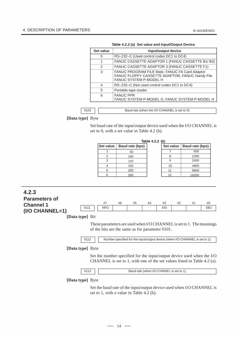
��� 4.2.2 (a) Set value and Input/Output Device
Set value Input/output device
0 RS–232–C (Used control codes DC1 to DC4)1 FANUC CASSETTE ADAPTOR 1 (FANUC CASSETTE B1/ B2)2 FANUC CASSETTE ADAPTOR 3 (FANUC CASSETTE F1)3 FANUC PROGRAM FILE Mate, FANUC FA Card Adaptor
FANUC FLOPPY CASSETTE ADAPTOR, FANUC Handy FileFANUC SYSTEM P-MODEL H
4 RS–232–C (Not used control codes DC1 to DC4)5 Portable tape reader6 FANUC PPR
FANUC SYSTEM P-MODEL G, FANUC SYSTEM P-MODEL H
0103 Baud rate (when the I/O CHANNEL is set to 0)
[Data type] Byte
Set baud rate of the input/output device used when the I/O CHANNEL isset to 0, with a set value in Table 4.2 (b).
��� � � � ��
Set value Baud rate (bps)1
23
456
Set value Baud rate (bps)7
89
600
12002400
10
12
48009600
19200
11
50
100110
150200
300
#7NFD0111
#6 #5 #4 #3ASI
#2 #1 #0SB2
[Data type] Bit
These parameters are used when I/O CHANNEL is set to 1. The meaningsof the bits are the same as for parameter 0101.
0112 Number specified for the input/output device (when I/O CHANNEL is set to 1)
[Data type] Byte
Set the number specified for the input/output device used when the I/OCHANNEL is set to 1, with one of the set values listed in Table 4.2 (a).
0113 Baud rate (when I/O CHNNEL is set to 1)
[Data type] Byte
Set the baud rate of the input/output device used when I/O CHANNEL isset to 1, with a value in Table 4.2 (b).
4.2.3Parameters of Channel 1 (I/O CHANNEL=1)

B–64160EN/01 4. DESCRIPTION OF PARAMETERS
15
#7NFD0121
#6 #5 #4 #3ASI
#2 #1 #0SB2
[Data type] Bit
These parameters are used when I/O CHANNEL is set to 2. The meaningsof the bits are the same as for parameter 0101.
0122 Number specified for the input/output device (when I/O CHANNEL is set to 2)
[Data type] Byte
Set the number specified for the input/output device used when I/OCHANNEL is set to 2, with a value in Table 4.2 (a).
0123 Baud rate (when the I/O CHANNEL is set to 2)
[Data type] Byte
Set the baud rate of the input/output device used when I/O CHANNEL isset to 2, with a value in Table 4.2 (b).
#70134
#6 #5 #4NCD
#3 #2SYN
#1PRY
#0
NOTEWhen this parameter is set, the power must be turned offbefore operation is continued.
[Data type] Bit
PRY Parity bit0: Not used1: Used
SYN Reset/alarm in protocol B0: Not reported to the host1: Reported to the host with SYN and NAK codes
NCD CD (signal quality detection) of the RS–232C interface0: Checked1: Not checked
4.2.4Parameters of Channel 2 (I/O CHANNEL=2)
4. DESCRIPTION OF PARAMETERS B–64160EN/01
16
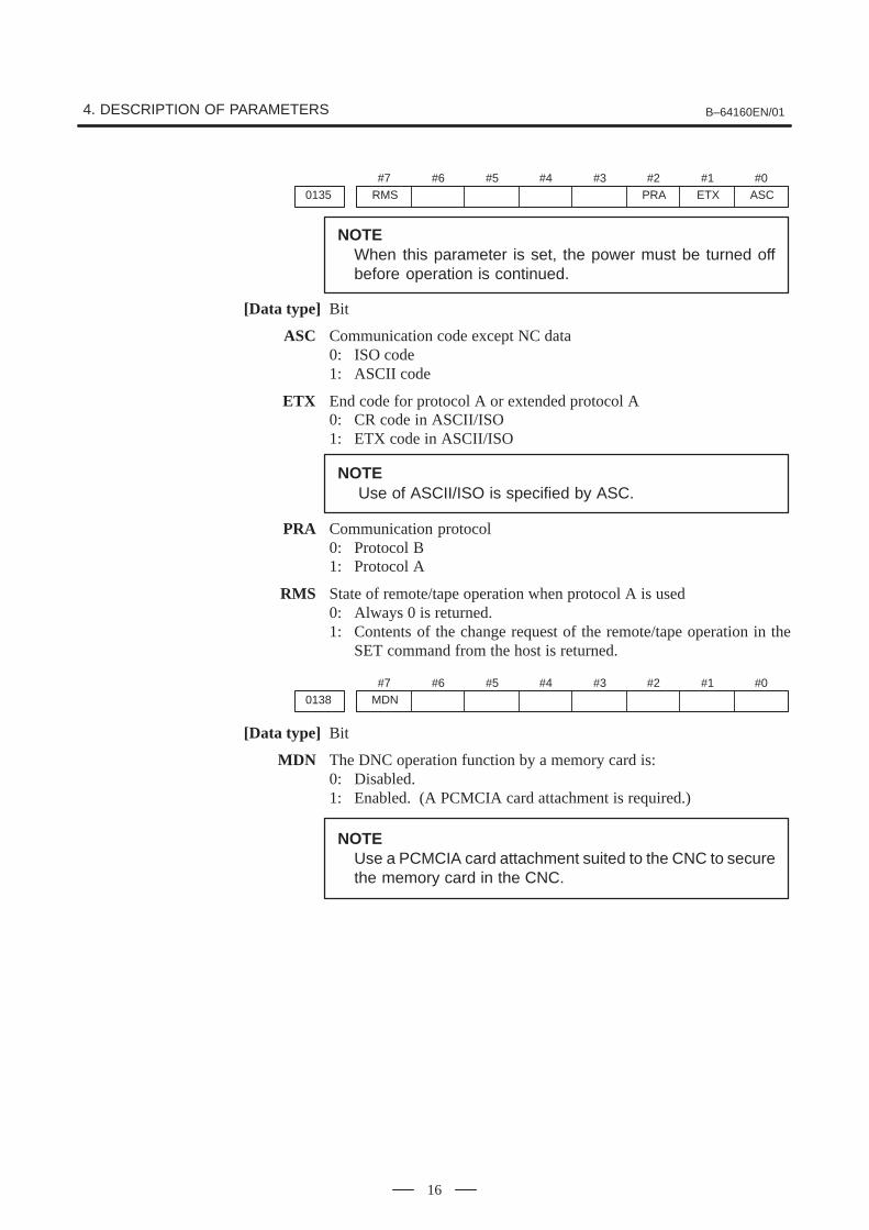
#7RMS0135
#6 #5 #4 #3 #2PRA
#1ETX
#0ASC
NOTEWhen this parameter is set, the power must be turned offbefore operation is continued.
[Data type] Bit
ASC Communication code except NC data0: ISO code1: ASCII code
ETX End code for protocol A or extended protocol A0: CR code in ASCII/ISO1: ETX code in ASCII/ISO
NOTEUse of ASCII/ISO is specified by ASC.
PRA Communication protocol0: Protocol B1: Protocol A
RMS State of remote/tape operation when protocol A is used0: Always 0 is returned.1: Contents of the change request of the remote/tape operation in the
SET command from the host is returned.
#7MDN0138
#6 #5 #4 #3 #2 #1 #0
[Data type] Bit
MDN The DNC operation function by a memory card is:0: Disabled.1: Enabled. (A PCMCIA card attachment is required.)
NOTEUse a PCMCIA card attachment suited to the CNC to securethe memory card in the CNC.

B–64160EN/01 4. DESCRIPTION OF PARAMETERS
17
#70140
#6 #5 #4 #3ECD
#2NCE
#1 #0BCC
NOTEWhen this parameter is set, the power must be turned offbefore operation is continued.
[Data type] Bit
BCC The BCC value (block check characters) for the DNC2 interface is:0: Checked.1: Not checked.
Even if the BCC value is not checked, the BCC value itself must bespecified.
NCE The ER (RS–232C) and TR (RS422) signals are:0: Checked.1: Not checked.
This parameter is provided only for the DNC2 interface.
ECD Error code of negative acknowledgment0: A four–digit hexadecimal error code is added to a negative
acknowledgment.1: No error code is added to a negative acknowledgment.
This parameter is provided only for the DNC2 interface.
NOTETo use FANUC DNC2 communications library for the hostcomputer, set this parameter to 1.
0143 Time limit specified for the timer monitoring a response (DNC2 interface)
NOTEWhen this parameter is set, the power must be turned offbefore operation is continued.
[Data type] Byte
[Unit of data] S
[Valid data range] 1 to 60 (The standard setting is 3.)
0144 Time limit specified for the timer monitoring the EOT signal (DNC2 interface)
NOTEWhen this parameter is set, the power must be turned offbefore operation is continued.
[Data type] Byte
[Unit of data] S
[Valid data range] 1 to 60 (The standard setting is 5.)
4.3PARAMETERS OFDNC2 INTERFACE

4. DESCRIPTION OF PARAMETERS B–64160EN/01
18
0145 Time required for switching RECV and SEND (DNC2 interface)
NOTEWhen this parameter is set, the power must be turned offbefore operation is continued.
[Data type] Byte
[Unit of data] S
[Valid data range] 1 to 60 (The standard setting is 1.)
0146 Number of times the system retries holding communication (DNC2 interface)
NOTEWhen this parameter is set, the power must be turned offbefore operation is continued.
[Data type] Byte
[Unit of data] S
[Valid data range] 1 to 10 (The standard setting is 3.)
Set the maximum number of times the system retries holdingcommunication with the remote device if the remote device uses aninvalid protocol in the data–link layer or the remote device does notrespond to the request.
0147Number of times the system sends the message in response to the NAK signal(DNC2 interface)
NOTEWhen this parameter is set, the power must be turned offbefore operation is continued.
[Data type] Byte
[Unit of data] Number of times
[Valid data range] 1 to 10 (The standard setting is 2.)
Set the maximum number of times the system retries sending the messagein response to the NAK signal.
0148 Number of characters in overrun (DNC2) interface)
NOTEWhen this parameter is set, the power must be turned offbefore operation is continued.
[Data type] Byte
[Valid data range] 10 to 225 (The standard setting is 10.)
Set the number of characters the system can receive after transmission isstopped (CS off).

B–64160EN/01 4. DESCRIPTION OF PARAMETERS
19
0149 Number of characters in the data section of the communication packet (DNC2interface)
NOTEWhen this parameter is set, the power must be turned offbefore operation is continued.
[Data type] Word
[Valid range] 80 to 256 (The standard setting is 256.)
The standard setting is 256. If the specified value is out of range, a value of80 or 256 is used.This parameter determines the maximum length of the packet used intransmission over the DNC2 interface. Including the two characters at thestart of the packet, the four characters used for a command, and the threecharacters at the end, the maximum number of characters in the packet isnine plus the number specified in parameter No.0149.
DLE STX Command Data section DEL ETX BCC
2 bytes 4 bytes 80 to 256 bytes 3 bytes
Length of the packet

4. DESCRIPTION OF PARAMETERS B–64160EN/01
20
#70002
#6 #5 #4 #3 #2 #1 #0RDG
[Data type] Bit
RDG Remote diagnosis is:0: Not performed.1: Performed.
If an RS–232C serial port is used to carry out remote diagnosis, connectand set up the modem, cable, and the like, then set 1 in this parameter.
#70201
#6 #5 #4 #3 #2NCR
#1ASC
#0SB2
[Data type] Bit
SB2 The number of stop bits is0: 1.1: 2.
To carry out remote diagnosis, set 0.
ASC The code to be used for data output is:0: ISO code.1: ASCII code.
To carry out remote diagnosis, set 1.
NCR EOB (end of block) is output as:0: ”LF””CR””CR”.1: Just as ”LF”.
To carry out remote diagnosis, set 1.
0203 Baud rate (for remote diagnosis)
[Data type] Byte
Set the baud rate of data input/output by remote diagnosis, with referenceto the tables given below.
When using an RS–232C serial port
Setting Baud rate (bps)
7
8
9
10
600
1200
2400
4800
9600
19200
Setting Baud rate (bps)
1
2
3
4
5
50
100
110
150
200
3006
11
12
NOTEThe tables above indicate the baud rates of communicationbetween the CNC and modem. The actual communicationbaud rate may be lowered, depending on the modem andcommunication line.
4.4PARAMETERS OFREMOTE DIAGNOSIS

B–64160EN/01 4. DESCRIPTION OF PARAMETERS
21
0204 Remote diagnosis channel
[Data type] Byte
[Valid data range] 0, 1, 2
The interface to be used for remote diagnosis is:
0, 1: RS–232C serial port 1 (channel 1).2 : RS–232C serial port 2 (channel 2).
0211 Password 1 for remote diagnosis
0212 Password 2 for remote diagnosis
0213 Password 3 for remote diagnosis
[Data type] 2–word
[Valid data range] 1 to 99999999
Specify a password for using the remote diagnosis function.
The remote diagnosis function has the following password settings. Datacan be protected by preventing a third party from accessing any systemparameter or machining program without permission.
Password 1:
Set a password for the whole service of the remote diagnosis function.(The whole remote diagnosis service is available only when this passwordis input on the host side (PC, for instance).)
Password 2:
Set a password of a part program. (The input/output, verification, and thelike of a program are possible only when this password is input on the hostside (PC, for instance).)
Password 3:
Set a password of a parameter. (The input/output or the like of a parameteris possible only when this password is input on the host side (PC, forinstance).)
NOTEOnce any value other than 0 is specified as a password, thepassword can be changed only when the same value isspecified in the corresponding keyword (parameters No. 221to No. 223). If any value other than 0 is specified as apassword, the password setting is not displayed on theparameter screen (blank display is provided). Take greatcare when setting the password.

4. DESCRIPTION OF PARAMETERS B–64160EN/01
22
0221 Keyword 1 for remote diagnosis
0222 Keyword 2 for remote diagnosis
0223 Keyword 3 for remote diagnosis
[Data type] 2–word
[Valid range] 1 to 99999999
Set a keyword corresponding to a password of the remote diagnosisfunction.
Keyword 1: Keyword for password 1 (parameter No. 211)
Keyword 2: Keyword for password 2 (parameter No. 212)
Keyword 3: Keyword for password 3 (parameter No. 213)
If any value other than 0 is specified as a password (parameters No. 211to No. 213), the password can be changed only when the same value isspecified as the corresponding keyword.
NOTEThe keyword value is reset to 0 at power–up. On the parameter screen, the keyword setting is notdisplayed (blank display is provided).

B–64160EN/01 4. DESCRIPTION OF PARAMETERS
23
#70300
#6 #5 #4 #3 #2 #1 #0PCM
[Data type] Bit
PCM If the CNC screen display function is enabled, when a memory cardinterface is provided on the NC side (HSSB connection),0 : The memory card interface on the NC side is used.1 : The memory card interface on the PC side is used.
If this parameter is set to 0 while the HSSB board is used for connection,the I/O channel specified in parameter No. 0020 is used.
If this parameter is set to 1, data input/output from and to the PC isperformed irrespective of the setting of parameter No. 20. This parameteris valid only while the CNC screen display function is active.
4.5PARAMETER OFMEMORY CARDINTERFACE

4. DESCRIPTION OF PARAMETERS B–64160EN/01
24
#70900
#6 #5 #4 #3 #2 #1ONS
#0DSV
[Data type] Bit
DSV The data server function is0: Enabled1: Disabled
ONS When the O number of the data server file name and the O number in anNC program do not match:0: The O number of the file name takes priority.1: The O number in the NC program takes priority.
0911 Altemate MDI character
[Data type] Word
[Set value] ASCII code (decimal)
0912 Character not provided in MDI keys
[Data type] Word
[Set value] ASCII code (decimal)
When specifying a character which is not provided as a MDI keys forHOST DIRECTORY of DATA SERVER SETTING–1, use theseparameters to assign an alternative key to that character.
[Example]If ODSERVERONCPROG is specified for HOST DIRECTORY, youcannot enter “\” with the MDI keys. To use “@” as an alternativecharacter, set 64 (ASCII code for @) in parameter No.0911 and 92 (ASCIIcode for \) in parameter No.0912. When
“DSERVER@NCPROG”is specified for HOST DIRECTORY, the data server converts it to
“ODSERVERONCPROG”.
NOTEWhen both parameters No.0911 and 0912 are set to 0, thedata server assumes the following setting:
No.0911 = 32 (blank) No.0912 = 92 (\)
4.6PARAMETERS OFDATA SERVER

B–64160EN/01 4. DESCRIPTION OF PARAMETERS
25
0921 OS selected for host computer 1 of data server
0922 OS selected for host computer 2 of data server
0923 OS selected for host computer 3 of data server
[Data type] Word
[Valid data range] 0 to 1
1 : UNIX or VMS is selected.
0 : Windows95/98/NT is selected.
0924 Latency setting for FOCAS1/Ethernet
[Data type] Word
[Unit of data] ms
[Valid data range] 0 to 255
Set service latency of FOCAS1/Ethernet while FOCAS1/Ethernet is usedtogether with the data server function.
If a value between 0 and 2 is set, 2 ms is assumed.

4. DESCRIPTION OF PARAMETERS B–64160EN/01
26
0931 Special character code corresponding to soft key [CHAR–1]
0932 Special character code corresponding to soft key [CHAR–2]
0933 Special character code corresponding to soft key [CHAR–3]
0934 Special character code corresponding to soft key [CHAR–4]
0935 Special character code corresponding to soft key [CHAR–5]
[Data type] Byte
[Valid data range] 32 to 95
These parameters are provided to allow a special character that is notprovided on the MDI panel but needed in a user name, password, or loginDIR to be input by pressing a soft key on the Ethernet parameter screen.
If a value other than 0 is input as a parameter, the special characterassigned to the corresponding input soft key [CHAR–1] to [CHAR–5] isdisplayed.
The special character codes correspond to the ASCII codes.
Sample special character codes
Specialcharacter Code Special
character Code Specialcharacter Code
Blank 32 ) 41 < 60! 33 * 42 > 62” 34 + 43 ? 63# 35 , 44 @ 64$ 36 – 45 [ 91% 37 . 46 ^ 92& 38 / 47 ¥ 93’ 39 : 58 ] 94( 40 ; 59 _ 95
4.7PARAMETERS OFETHERNET

B–64160EN/01 4. DESCRIPTION OF PARAMETERS
27
#70960
#6 #5 #4 #3PMN
#2MD2
#1MD1
#0SLV
[Data type] Bit
SLV When the power mate CNC manager is selected, the screen displays:0 : One slave.1 : Up to four slaves with the screen divided into four.
MD1,MD2 These parameters set a slave parameter input/output destination.
MD2 MD1 Input/output destination
0 0 Part program storage0 1 Memory card
In either case, slave parameters are output in program format.
PMN The power mate CNC manager function is:0 : Enabled.1 : Disabled. (Communication with slaves is not performed.)
4.8PARAMETERS OFPOWER MATE CNCMANAGER

4. DESCRIPTION OF PARAMETERS B–64160EN/01
28
#71001
#6 #5 #4 #3 #2 #1 #0INM
NOTEWhen this parameter is set, the power must be turned offbefore operation is continued.
[Data type] Bit
INM Least command increment on the linear axis0 : In mm (metric system machine)1 : In inches (inch system machine)
#7IDG1002
#6 #5 #4XIK
#3AZR
#2SFD
#1DLZ
#0JAX
[Data type] Bit
JAX Number of axes controlled simultaneously in manual continuous feed,manual rapid traverse and manual reference position return0 : 1 axis1 : 3 axes
DLZ Function setting the reference position without dog0 : Disabled1 : Enabled (enabled for all axes)
NOTE1 This function can be specified for each axis by DLZx, bit 1 of
parameter No.1005.2 For a system including an axis of Cs contour control or
spindle positioning, avoid using this parameter. Use bit 1(DLZx) of parameter No. 1005 instead to set just a requiredaxis.
SFD The function for shifting the reference position is0: Not used.1: Used.
AZR When no reference position is set, the G28 command causes:0: Reference position return using deceleration dogs (as during manual
reference position return) to be exected.1: P/S alarm No.090 to be issued.
NOTEWhen reference position return without dogs is specified,(when bit 1 (DLZ) of parameter No.1002 is set to 1 or bit 1(DLZx) of parameter No.1005 is set to 1) the G28 commandspecified before a reference position is set causes P/Salarm No.090 to be issued, regardless of the setting of AZR.
4.9PARAMETERS OFAXIS CONTROL/INCREMENT SYSTEM

B–64160EN/01 4. DESCRIPTION OF PARAMETERS
29
XIK When LRP, bit 1 of parameter No.1401, is set to 0, namely, whenpositioning is performed using non–linear type positioning, if aninterlock is applied to the machine along one of axes in positioning,0: The machine stops moving along the axis for which the interlock is
applied and continues to move along the other axes.1: The machine stops moving along all the axes.
IDG When the reference position is set without dogs, automatic setting of theIDGx parameter (bit 0 of parameter No.1012) to prevent the referenceposition from being set again is:0 : Not performed.1 : Performed.
#7
1004 IPR#6 #5 #4 #3 #2 #1 #0
ISA
NOTEWhen this parameter is set, the power must be turned offbefore operation is continued.
[Data type] Bit
ISA The least input increment and least command increment are set.
ISA Least input increment and least command increment Symbol
0 0.001 mm, 0.001 deg, or 0.0001 inch IS–B
1 0.01 mm, 0.01 deg, or 0.001 inch IS–A
IPR Whether the least input increment for each axis is set to a value 10 times aslarge as the least command increment is specified, in increment systemsof IS–B at setting mm.0: The least input increment is not set to a value 10 times as larg as the
least command increment.1: The least input increment is set to a value 10 times as large as the least
command increment.
If IPR is set to 1, the least input increment is set as follows:
Input increment Least input increment
IS–B 0.01 mm, 0.01 deg, or 0.0001 inch
NOTEFor IS–A, the least input increment cannot be set to a value10 times as large as the least command increment.The least input increment is not multiplied by 10 also whenthe calculator–type decimal point input (bit 0 (DPI) ofparameter No. 3401) is used.

4. DESCRIPTION OF PARAMETERS B–64160EN/01
30
#7
1005
#6 #5EDMx
#4EDPx
#3HJZx
#2 #1DLZx
#0ZRNx
[Data type] Bit axis
ZRNx When a command specifying the movement except for G28 is issued inautomatic operation (memory, MDI, or DNC operation) and when areturn to the reference position has not been performed since the powerwas turned on0 : An alarm is generated (P/S alarm 224).1 : An alarm is not generated.
NOTEThe state in which the reference position has not beenestablished refers to that state in which reference positionreturn has not been performed after power–on when anabsolute position detector is not being used, or that state inwhich the association of the machine position with the positiondetected with the absolute position detector has not beencompleted (see the description of bit 4 (APZx) of parameterNo. 1815) when an absolute position detector is being used.
DLZx Function for setting the reference position without dogs0 : Disabled1 : Enabled
NOTEWhen DLZ of parameter No.1002 is 0, DLZx is enabled.When DLZ of parameter No.1002 is 1, DLZx is disabled, andthe function for setting the reference position without dogsis enabled for all axes.
HJZx When a reference position is already set:0 : Manual reference position return is performed with deceleration sogs.1 : Manual reference position return is performed using rapid traverse
without deceleration dogs, or manual reference position return isperformed with deceleration dogs, depending on the setting of bit 7(SJZ) of parameter No.0002.
NOTEWhen reference position return without dogs is specified,(see bit 1 (DLZ) of parameter No.1002) reference positionreturn after a reference position is set is performed usingrapid traverse, regardless of the setting of HJZ.
EDPx External deceleration signal in the positive direction for each axis0 : Valid only for rapid traverse1 : Valid for rapid traverse and cutting feed
EDMx External deceleration signal in the negative direction for each axis0 : Valid only for rapid traverse1 : Valid for rapid traverse and cutting feed

B–64160EN/01 4. DESCRIPTION OF PARAMETERS
31
#7
1006
#6 #5ZMIx
#4 #3 #2 #1ROSx
#0ROTx
NOTEWhen this parameter is set, the power must be turned offbefore operation is continued.
[Data type] Bit axis
ROTx, ROSx Setting linear or rotation axis.
ROSx ROTx Meaning
0 0 Linear axis(1) Inch/metric conversion is done.(2) All coordinate values are linear axis type.
(Is not rounded in 0 to 360�)(3) Stored pitch error compensation is linear axis type
(Refer to parameter No.3624)
0 1 Rotation axis (A type)(1) Inch/metric conversion is not done.(2) Machine coordinate values are rounded in 0 to 360�.
Absolute coordinate values are rounded or not roundedby parameter No.1008#0(ROAx) and #2(RRLx).
(3) Stored pitch error compensation is the rotation type.(Refer to parameter No.3624)
(4) Automatic reference position return (G28, G30) is donein the reference position return direction and the moveamount does not exceed one rotation.
1 0 Setting is invalid (unused)
1 1 Rotation axis (B type)(1) Inch/metric conversion, absolute coordinate values and
relative coordinate values are not done.(2) Machine coordinate values, absolute coordinate values
and relative coordinate values are linear axis type. (Isnot rounded in 0 to 360�).
(3) Stored pitch error compensation is linear axis type (Re-fer to parameter No.3624)
(4) Cannot be used with the rotation axis roll over functionand the index table indexing function (M series)
ZMIx The direction of reference position return.0 : Positive direction1 : Negative direction
NOTEThe direction of the initial backlash, which occurs whenpower is switched on, is opposite to the direction of areference position return.
4. DESCRIPTION OF PARAMETERS B–64160EN/01
32
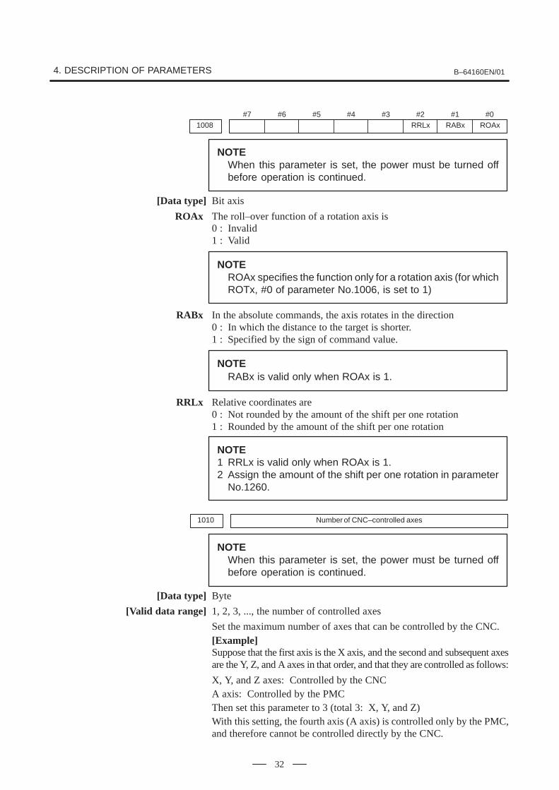
#71008
#6 #5 #4 #3 #2RRLx
#1RABx
#0ROAx
NOTEWhen this parameter is set, the power must be turned offbefore operation is continued.
[Data type] Bit axis
ROAx The roll–over function of a rotation axis is0 : Invalid1 : Valid
NOTEROAx specifies the function only for a rotation axis (for whichROTx, #0 of parameter No.1006, is set to 1)
RABx In the absolute commands, the axis rotates in the direction0 : In which the distance to the target is shorter.1 : Specified by the sign of command value.
NOTERABx is valid only when ROAx is 1.
RRLx Relative coordinates are0 : Not rounded by the amount of the shift per one rotation1 : Rounded by the amount of the shift per one rotation
NOTE1 RRLx is valid only when ROAx is 1.2 Assign the amount of the shift per one rotation in parameter
No.1260.
1010 Number of CNC–controlled axes
NOTEWhen this parameter is set, the power must be turned offbefore operation is continued.
[Data type] Byte
[Valid data range] 1, 2, 3, ..., the number of controlled axes
Set the maximum number of axes that can be controlled by the CNC.[Example]Suppose that the first axis is the X axis, and the second and subsequent axesare the Y, Z, and A axes in that order, and that they are controlled as follows:
X, Y, and Z axes: Controlled by the CNCA axis: Controlled by the PMCThen set this parameter to 3 (total 3: X, Y, and Z)With this setting, the fourth axis (A axis) is controlled only by the PMC,and therefore cannot be controlled directly by the CNC.

B–64160EN/01 4. DESCRIPTION OF PARAMETERS
33
#71012
#6 #5 #4 #3 #2 #1 #0IDGx
[Data type] Bit axis
IDGx The function for setting the reference position again, without dogs, is:0 : Not inhibited.1 : Inhibited.
NOTE1 IDGx is enabled when the IDG parameter (bit 7 of parameter
No.1002) is 1.2 When the function for setting the reference position, without
dogs, is used, and the reference position is lost for somereason, an alarm requesting reference position return(No.300) is generated when the power is next turned on. Ifthe operator performs reference position return, as a resultof mistakenly identifying the alarm as that requesting theoperator to perform a normal reference position return, aninvalid reference position may be set. To prevent such anoperator error, the IDGx parameter is provided to prevent thereference position from being set again without dogs.(1) If the IDG parameter (bit 7 of parameter No.1002) is set
to 1, the IDGx parameter (bit 0 of parameter No.1012)is automatically set to 1 when the reference position isset using the function for setting the reference positionwithout dogs. This prevents the reference position frombeing set again without dogs.
(2) Once the reference position is prevented from being setfor an axis again, without dogs, any attempt to set thereference position for the axis without dogs results in theoutput of an alarm (No.090).
(3) When the reference position must be set again withoutdogs, set IDGx to 0 before setting the reference position.

4. DESCRIPTION OF PARAMETERS B–64160EN/01
34
1020 Program axis name for each axis
[Data type] Byte axis
Set the program axis name for each controlled axis, using one of the valueslisted in the following table:
Axisname Setting Axis
name Setting Axisname Setting Axis
name Setting
X 88 U 85 A 65 T 84
Y 89 V 86 B 66
Z 90 W 87 C 67
NOTE1 The same axis name cannot be assigned to more than one
axis.2 When the addresses A, B, U, V, and W are used as the axis
name, refer to the parameters ABM and UVW (No. 16200 #6and #7).
3 When the secondary auxiliary function is provided, theaddress used by the secondary auxiliary function cannot beused as an axis name.
1022 Setting of each axis in the basic coordinate system
NOTEWhen this parameter is set, power must be turned off beforeoperation is continued.
[Data type] Byte axis
To determine the following planes used for circular interpolation, cuttercompensation C (for the M series), tool nose radius compensation (for theT series), etc., each control axis is set to one of the basic three axes X, Y,and Z, or an axis parallel to the X, Y, or Z axis.G17: Plane Xp–YpG18: Plane Zp–XpG19: Plane Yp–ZpOnly one axis can be set for each of the three basic axes X, Y, and Z, buttwo or more parallel axes can be set.
Set value Meaning
0 Neither the basic three axes nor a parallel axis
1 X axis of the basic three axes
2 Y axis of the basic three axes
3 Z axis of the basic three axes
5 Axis parallel to the X axis
6 Axis parallel to the Y axis
7 Axis parallel to the Z axis
B–64160EN/01 4. DESCRIPTION OF PARAMETERS
35
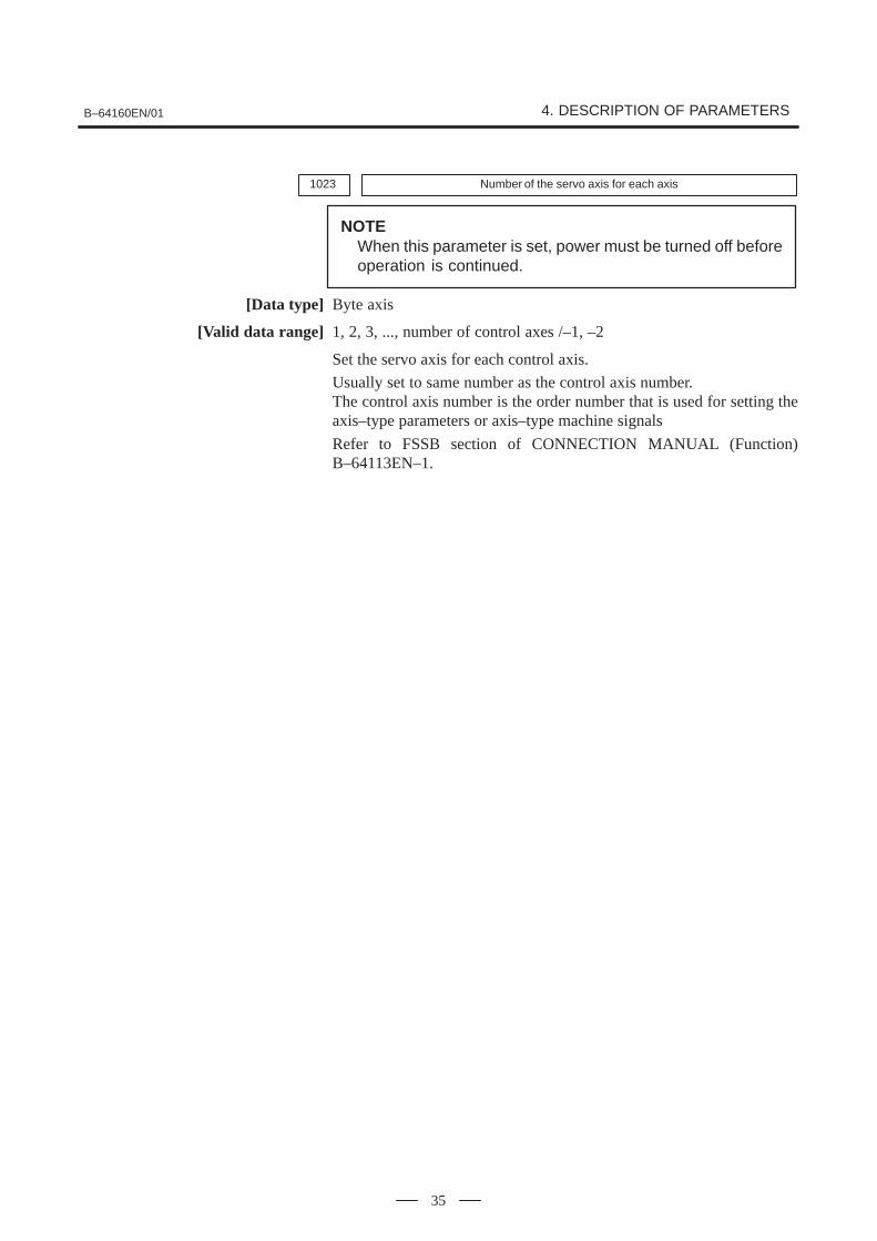
1023 Number of the servo axis for each axis
NOTEWhen this parameter is set, power must be turned off beforeoperation is continued.
[Data type] Byte axis
[Valid data range] 1, 2, 3, ..., number of control axes /–1, –2
Set the servo axis for each control axis.
Usually set to same number as the control axis number.The control axis number is the order number that is used for setting theaxis–type parameters or axis–type machine signals
Refer to FSSB section of CONNECTION MANUAL (Function)B–64113EN–1.

4. DESCRIPTION OF PARAMETERS B–64160EN/01
36
#7
1201
#6 #5AWK
#4 #3 #2ZCL
#1 #0
[Data type] Bit
ZCL Local coordinate system when the manual reference position return isperformed0 : The local coordinate system is not canceled.1 : The local coordinate system is canceled.
AWK When the workpiece zero point offset value is changed0 : The absolute position display changed when the next bufforing block
is performed.1 : The absolute position display is changed immediately.
Changed value is valid ofter baffering the next block.
#7
1202
#6 #5 #4G52
#3RLC
#2 #1 #0
[Data type] Bit
RLC Local coordinate system is0 : Not cancelled by reset1 : Cancelled by reset
G52 In local coordinate system setting (G52), a cutter compensation vector is:0 : Not considered.1 : Considered.
NOTESelect a local coordinate system setting operation whencutter compensation is applied, and when two or moreblocks specifying no movement exist prior to thespecification of G52, or when G52 is specified after cuttercompensation mode is canceled without eliminating theoffset vector.
#71203
#6 #5 #4 #3 #2 #1 #0EMC
[Data type] Bit
EMC The extended external machine zero point shift function is:0: Disabled.1: Enabled.
NOTE1 To use the extended external machine zero point shift
function, the external machine zero point shift function or theexternal data input function is required.
2 When the extended machine zero point shift function isenabled, the conventional external machine zero point shiftfunction is disabled.
4.10PARAMETERS OFCOORDINATES

B–64160EN/01 4. DESCRIPTION OF PARAMETERS
37
1220 External workpiece zero point offset value
[Data type] 2–word axis
[Unit of data]Input increment IS–A IS–B Unit
Linear axis (input in mm) 0.01 0.001 mm
Linear axis (input in inches) 0.001 0.0001 inch
Rotation axis 0.01 0.001 deg
[Valid data range] –99999999 to 99999999
This is one of the parameters that give the position of the origin ofworkpiece coordinate system (G54 to G59). It gives an offset of theworkpiece origin common to all workpiece coordinate systems. Ingeneral, the offset varies depending on the workpiece coordinate systems.The value can be set from the PMC using the external data input function.
1221 Workpiece zero point offset value in workpiece coordinate system 1 (G54)
1222 Workpiece zero point offset value in workpiece coordinate system 2(G55)
1223 Workpiece zero point offset value in workpiece coordinate system 3(G56)
1224 Workpiece zero point offset value in workpiece coordinate system 4 (G57)
1225 Workpiece zero point offset value in workpiece coordinate system 5 (G58)
1226 Workpiece zero point offset value in workpiece coordinate system 6 (G59)
[Data type] 2–word axis[Unit of data]
Input increment IS–A IS–B Unit
Linear axis (input in mm) 0.01 0.001 mm
Linear axis (input in inches) 0.001 0.0001 inch
Rotation axis 0.01 0.001 deg
[Valid data range] –99999999 to 99999999
The workpiece zero point offset values in workpiece coordinate systems 1to 6 (G54 to G59) are set.
Workpiece coordinate system 1 (G54)
Workpiece zero point offset
Origin of machine coordinate system
Workpiece coordinate system 2 (G55)
4. DESCRIPTION OF PARAMETERS B–64160EN/01
38
NOTEThe workpiece origin offset can also be set using theworkpiece coordinate system screen.
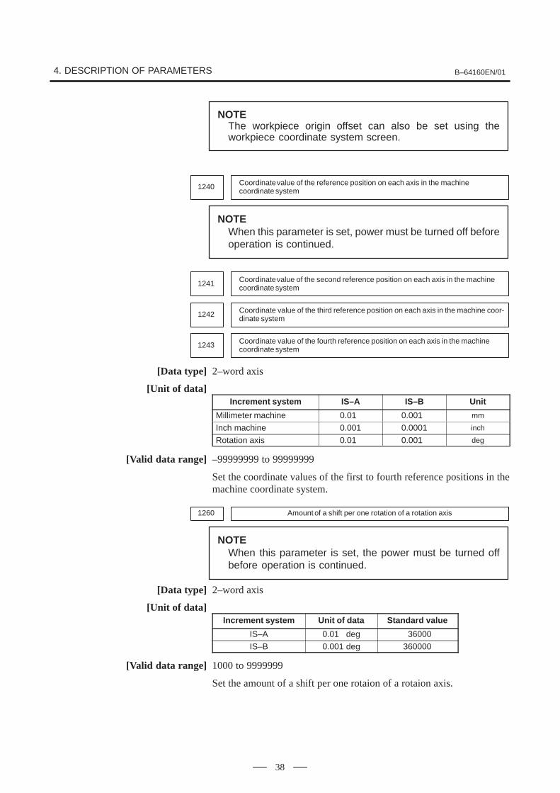
1240 Coordinate value of the reference position on each axis in the machine coordinate system
NOTEWhen this parameter is set, power must be turned off beforeoperation is continued.
1241 Coordinate value of the second reference position on each axis in the machinecoordinate system
1242 Coordinate value of the third reference position on each axis in the machine coor-dinate system
1243 Coordinate value of the fourth reference position on each axis in the machinecoordinate system
[Data type] 2–word axis
[Unit of data]Increment system IS–A IS–B Unit
Millimeter machine 0.01 0.001 mm
Inch machine 0.001 0.0001 inch
Rotation axis 0.01 0.001 deg
[Valid data range] –99999999 to 99999999
Set the coordinate values of the first to fourth reference positions in themachine coordinate system.
1260 Amount of a shift per one rotation of a rotation axis
NOTEWhen this parameter is set, the power must be turned offbefore operation is continued.
[Data type] 2–word axis
[Unit of data]Increment system Unit of data Standard value
IS–A 0.01 deg 36000
IS–B 0.001 deg 360000
[Valid data range] 1000 to 9999999
Set the amount of a shift per one rotaion of a rotaion axis.

B–64160EN/01 4. DESCRIPTION OF PARAMETERS
39
1280First address of the signal group used by the external machine zero point shiftextension
[Data type] Word
[Valid data range] 0 to 65535
Set the first address of the signal group used by the external machine zeropoint shift extension. If 100 is specified, R0100 to R0115 can be used.
Shift amount of external machine zero point shift extension forthe first axis (LOW)
Shift amount of external machine zero point shift extension forthe first axis (HIGH)
Shift amount of external machine zero point shift extension forthe second axis (LOW)
Shift amount of external machine zero point shift extension forthe second axis (HIGH)
Shift amount of external machine zero point shift extension forthe eighth axis (LOW)
Shift amount of external machine zero point shift extension forthe eighth axis (HIGH)
R0100
R0101
R0102
R0103
R0114
R0115
:
:
:
:
::
:
:
NOTE1 This parameter is valid when bit 0 (EMC) of parameter No.
1203 is set to 1.2 If the specified number is not present, the external machine
zero point shift extension is disabled.3 A shift amount of the external machine zero point shift
extension can be written from the C executer or macroexecuter.

4. DESCRIPTION OF PARAMETERS B–64160EN/01
40
#7
1300
#6 #5 #4 #3 #2 #1 #0BFA LZR LMS OUT
[Data type] Bit
OUT The area inside or outside of the stored stroke check 2 is set as aninhibition area (setting by the parameters No.1322 and No.1323).0: Inside1: Outside
LMS The EXLM signal for switching stored stroke check0: Disabled1: Enabled
NOTEStored stroke check 1 supports two pairs of parameters forsetting the prohibited area. The stored stroke limit switchingsignal is used to enable either of the prohibited areas set withthese parameter pairs.(1) Prohibited area I: Parameters No.1320 and No.1321(2) Prohibited area II: Parameters No.1326 and No.1327
LZR Checking of stored stroke check 1 during the time from power–on to themanual position reference return0: The stroke check 1 is checked.1: The stroke check 1 is not checked
NOTEWhen an absolute position detector is used and a referenceposition is already set upon power–up, stored stroke limitcheck 1 is started immediately after power–up, regardless ofthe setting.
BFA When a command that exceeds a stored stroke check is issued0: An alarm is generated after the stroke check is exceeded.1: An alarm is generated before the stroke check is exceeded.
NOTEThe tool stops at a point up to F/7500 mm short of or aheadof the boundary.(F: Feedrate when the tool reaches the boundary (mm/min))
#71301
#6 #5 #4OF1
#3 #2 #1 #0DLM
[Data type] Bit
DLM The stored stroke limit switching signal for each axial direction is:0: Enabled.1: Disabled.
OF1 If the tool is moved into the range allowed on the axis after an alarm israised by stored stroke check 1,0: The alarm is not canceled before a reset is made.1: The OT alarm is immediately canceled.
4.11PARAMETERS OFSTROKE CHECK

B–64160EN/01 4. DESCRIPTION OF PARAMETERS
41
CAUTIONIn the cases below, the automatic release function isdisabled. To release an alarm, a reset operation is required.1 When a setting is made to issue an alarm before a stored
stroke limit is exceeded (bit 7 (BFA) of parameter No.1300)
2 When an another overtravel alarm (such as stored strokecheck 2 and stored stroke check 3) is already issued
#7
1310
#6 #5 #4 #3 #2 #1 #0OT2x
[Data type] Bit axisOT2x Whether stored stroke check 2 is checked for each axis is set.
0: Stored stroke check 2 is not checked.1: Stored stroke check 2 is checked.
1320 Coordinate value I of stored stroke check 1 in the positive direction on each axis
1321 Coordinate value I of stored stroke check 1 in the negative direction on each axis
[Data type] 2–word axis
[Unit of data]Increment system IS–A IS–B Unit
Millimeter machine 0.01 0.001 mm
Inch machine 0.001 0.0001 inch
Rotation axis 0.01 0.001 deg
[Valid data range] –99999999 to 99999999The coordinate values of stored stroke check 1 in the positive and negativedirections are setfor each axis in the machine coordinate system. Theoutside area of the two checks set in the parameters is inhibited.
ÇÇÇÇÇÇÇÇÇÇÇÇÇÇÇÇÇÇÇÇÇÇÇÇÇÇÇÇÇÇÇÇÇÇÇÇÇÇÇÇÇÇÇÇÇÇÇÇÇÇÇÇÇÇÇÇÇÇÇÇÇÇÇÇÇÇÇÇÇÇÇÇ
(Xp,Yp,Zp)Set the machine coordinates of theboundaries in the positive direction(Xp, Yp, and Zp) using parameter No.1320, and those of the boundaries inthe negative direction (Xm, Ym, andZm) using parameter No. 1321. Theprohibited area thus becomes thehatched area in the figure on the left.
(Xm,Ym,Zm)

4. DESCRIPTION OF PARAMETERS B–64160EN/01
42
NOTE1 For axes with diameter specification, a diameter value must
be set.2 When the parameters are set as follows, the stroke becomes
infinite:parameter 1320 < parameter 1321
For movement along the axis for which infinite stroke is set,only increment commands are available. (The stored strokelimit switching signal also becomes invalid.) If an absolutecommand is issued for this axis, the absolute register mayoverflow, and normal movement will not result.
3 The prohibited area specified with these parameters isinvalid if bit 2 (LMS) of parameter No. 1300 is set to 1 andstored stroke limit switching signal EXLM is set to 1. In sucha case, the settings of parameters No. 1326 and 1327 areused, instead.
1322 Coordinate value of stored stroke check 2 in the positive direction on each axis
1323 Coordinate value of stored stroke check 2 in the negative direction on each axis
[Data type] 2–word axis
[Unit of data]Increment system IS–A IS–B Unit
Millimeter machine 0.01 0.001 mm
Inch machine 0.001 0.0001 inch
Rotation axis 0.01 0.001 deg
[Valid data range] –99999999 to 99999999Set the coordinate values of stored stroke check 2 in the positive andnegative directions foreach axis in the machine coordinate system. OUT,#0 of parameter 1300, sets either the area outside of the area insidespecified by two checks are the inhibition area.
ÇÇÇÇÇÇÇÇÇÇÇÇÇÇÇÇÇÇÇÇÇÇÇÇÇÇÇÇÇÇÇÇÇÇÇÇÇÇÇÇÇÇÇÇÇÇÇÇÇÇÇÇÇÇÇÇÇÇÇÇ
(Xp,Yp,Zp)
(Xm,Ym,Zm)
Set the machine coordinates of theboundaries in the positive direction(Xp, Yp, and Zp) using parameterNo. 1322, and those of the bound-aries in the negative direction (Xm,Ym, and Zm) using parameter No.1323. The prohibited area thusbecomes the hatched area in thefigure on the left.
(1) When the prohibited area is inside the boundaries (OUT = 0)
(2) When the prohibited area is outside the boundaries (OUT = 1)
ÇÇÇÇÇÇÇÇÇÇ
ÇÇÇÇÇÇÇÇÇÇÇÇÇÇ
ÇÇÇÇÇÇÇÇÇ
(Xp,Yp,Zp)
(Xm,Ym,Zm)

B–64160EN/01 4. DESCRIPTION OF PARAMETERS
43
1326 Coordinate value II of stored stroke check 1 in the positive direction on each axis
1327 Coordinate value II of stored stroke check 1 in the negative direction on each axis
[Data type] 2–word axis
[Unit of data]Increment system IS–A IS–B Unit
Millimeter machine 0.01 0.001 mm
Inch machine 0.001 0.0001 inch
Rotation axis 0.01 0.001 deg
[Valid data range] –99999999 to 99999999
Set the coordinate values of stored stroke check 1 in the positive andnegative directions foreach axis in the machine coordinate system.
When stroke check switching signal EXLM is ON, stroke check arechecked with parameters 1326 and 1327, not with parameters 1320 and1321. The area outside that set by parameters 1326 and 1327 is inhibited.
NOTE1 Specify diameter values for any axes for which diameter
programming is specified.2 These parameters are invalid if bit 2 (LMS) of parameter No.
1300 is set to 0, or if stored stroke limit switching signalEXLM is set to 0. In such a case, the settings of parametersNo. 1320 and 1321 are used, instead.

4. DESCRIPTION OF PARAMETERS B–64160EN/01
44
#7
1401
#6RDR
#5 #4RF0
#3 #2 #1LRP
#0RPD
[Data type] Bit
RPD Manual rapid traverse during the period from power–on time to thecompletion of the reference position return.0: Disabled (Jog feed is performed.)1: Enabled
LRP Positioning (G00)0: Positioning is performed with non–linear type positioning so that the
tool moves along each axis independently at rapid traverse.1: Positioning is performed with linear interpolation so that the tool
moves in a straight line.
RF0 When cutting feedrate override is 0% during rapid traverse,0: The machine tool does not stop moving.1: The machine tool stops moving.
RDR Dry run for rapid traverse command0: Disabled1: Enabled
#7
1402
#6 #5 #4 #3 #2 #1JOV
#0
[Data type] Bit
JOV Job override is:0: Enabled1: Disabled (tied to 100%)
#7
1404 FC0#6 #5
EDR#4 #3
FRV#2
F8A#1
DLF#0
HFC
[Data type] Bit
HFC The feedrate for helical interpolation is:0: Clamped so that the feedrates along an arc and linear axis do not
exceed the maximum cutting feedrate specified by parameter(No.1422 or 1430).
1: Clamped so that the composite feedrate along an arc and linear axis doesnot exceed the maximum cutting feedrate specified by parameter(No.1422).
DLF After a reference potition is set, manual reference position returnperformed at:0 : Rapid traverse rate (parameter No.1420)1 : Manual rapid traverse rate (parameter No.1424)
NOTEThis parameter selects a feedrate for reference positionreturn performed without dogs. This parameter also selectsa feedrate when manual reference position return isperformed according to bit 7 (SJZ) of parameter No.0002using rapid traverse without deceleration dogs after areference position is set.
4.12PARAMETERS OFFEEDRATE

B–64160EN/01 4. DESCRIPTION OF PARAMETERS
45
F8A Valid data range for an F command with a decimal point
Increment system Units IS–A, IS–B
Millimeter input mm/min 0.001 to 99999.999.
Inch input inch/min 0.00001 to 999.99999.
Rotation axis (mm) deg/min 1 to 240000.
Rotation axis (inch) deg/min 1 to 9600.
Increment system Units IS–A, IS–B
Millimeter input mm/min 0.001 to 240000.
Inch input inch/min 0.00001 to 9600.
Rotation axis deg/min 1 to 240000.
FRV For inch input, the valid range of the feedrate specified for feed perrevolution is:0 : Standard range. (F0.000001 to 9.999999 inches per revolution)1 : Extended to F50.0 inches per revolution. (F0.000001 to 50.000000
inches per revolution)
EDR The external deceleration speed in liner interpolation type positioning isset in:0: Parameter No. 1426.1: Parameter No. 1427, for the first axis.
FC0 Specifies the behavior of the machine tool when a block (G01, G02, G03,etc.) containing a feedrate command (F command) that is 0 is issuedduring automatic operation, as follows:0: A P/S alarm (No.011) is displayed, and the block is not executed.1: No alarm is displayed, and the block is executed.
1410 Dry run rate
[Data type] Word[Unit of data]
[Valid data range]
��������� ������ ���� �� �������� ���� �����
��������� ������ ���� �� ����� !�" � !#
Millimeter machine 1 mm/min 6 to 15000
Inch machine 0.1 inch/min 6 to 6000
Set the dry run rate when the manual feedrate is overridden by 100%.
1411 Cutting feedrate in the automatic mode at power–on
This parameter can be set at the “Setting screen”.[Data type] Word
[Unit of data][Valid data range]
��������� ������ ���� �� �������� ���� �����
��������� ������ ���� �� ����� !�" � !#
Millimeter machine 1 mm/min 6 to 32767
Inch machine 0.1 inch/min 6 to 32767
When the machine requires little change in cutting feedrate duringcutting, a cutting feedrate can be specified in the parameter. Thiseliminates the need to specify a cutting feedrate (F command) in the NCprogram.
0:
1:

4. DESCRIPTION OF PARAMETERS B–64160EN/01
46
The cutting feedrate set by this parameter is valid after the CNC is placedin the clear state by power–up or a reset until a feedrate is specified by aprogram command (F command). After a feedrate is specified by the Fcommand, the feedrate becomes valid.
1420 Rapid traverse rate for each axis
[Data type] 2–word axis
[Unit of data][Valid data range]
��������� ������ ���� �� �������� ���� �����
��������� ������ ���� �� ����� !�" � !#
Millimeter machine 1 mm/min 30 to 240000
Inch machine 0.1 inch/min 30 to 96000
Rotation axis 1 deg/min 30 to 240000
Set the rapid traverse rate when the rapid traverse override is 100% foreach axis.
1422 Maximum cutting feedrate for all axes
[Data type] 2–word[Unit of data]
[Valid data range]
��������� ������ ���� �� �������� ���� �����
��������� ������ ���� �� ����� !�" � !#
Millimeter machine 1 mm/min 6 to 240000
Inch machine 0.1 inch/min 6 to 96000
Specify the maximum cutting feedrate.A feedrate in the tangential direction is clamped in cutting feed so that itdoes not exceed the feedrate specified in this parameter.
NOTEA maximum cutting feedrate can be specified for each axisonly during linear interpolation and circular interpolation byusing parameter No. 1430.
1423 Feedrate in manual continuous feed (jog feed) for each axis
[Data type] Word axis
(1) Specify a jog feedrate at feed per minute with an override of 100%.[Unit of data, valid range]
��������� ������ ���� �� �������� ���� �����
��������� ������ ���� �� ����� !�" � !#
Millimeter machine 1 mm/min 6 to 15000
Inch machine 0.1 inch/min 6 to 6000
Rotaiton axis 1 deg/min 6 to 15000
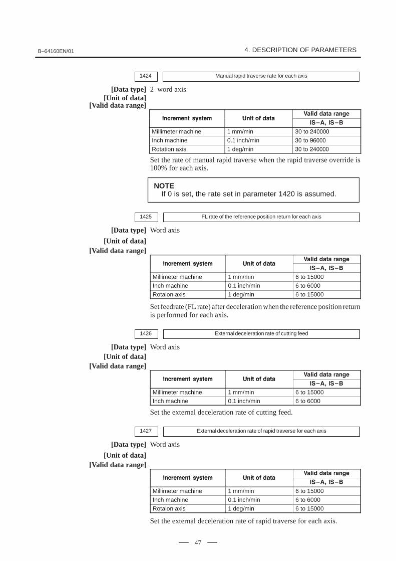
B–64160EN/01 4. DESCRIPTION OF PARAMETERS
47
1424 Manual rapid traverse rate for each axis
[Data type] 2–word axis[Unit of data]
[Valid data range]
��������� ������ ���� �� �������� ���� �����
��������� ������ ���� �� ����� !�" � !#
Millimeter machine 1 mm/min 30 to ������
Inch machine 0.1 inch/min �� �� � ����
Rotation axis 1 deg/min �� �� ������
Set the rate of manual rapid traverse when the rapid traverse override is100% for each axis.
NOTEIf 0 is set, the rate set in parameter 1420 is assumed.
1425 FL rate of the reference position return for each axis
[Data type] Word axis
[Unit of data][Valid data range]
��������� ������ ���� �� �������� ���� �����
��������� ������ ���� �� ����� !�" � !#
Millimeter machine 1 mm/min 6 to 15000
Inch machine 0.1 inch/min 6 to 6000
Rotaion axis 1 deg/min 6 to 15000
Set feedrate (FL rate) after deceleration when the reference position returnis performed for each axis.
1426 External deceleration rate of cutting feed
[Data type] Word axis[Unit of data]
[Valid data range]
��������� ������ ���� �� �������� ���� �����
��������� ������ ���� �� ����� !�" � !#
Millimeter machine 1 mm/min 6 to 15000
Inch machine 0.1 inch/min 6 to 6000
Set the external deceleration rate of cutting feed.
1427 External deceleration rate of rapid traverse for each axis
[Data type] Word axis
[Unit of data][Valid data range]
��������� ������ ���� �� �������� ���� �����
��������� ������ ���� �� ����� !�" � !#
Millimeter machine 1 mm/min 6 to 15000
Inch machine 0.1 inch/min 6 to 6000
Rotaion axis 1 deg/min 6 to 15000
Set the external deceleration rate of rapid traverse for each axis.

4. DESCRIPTION OF PARAMETERS B–64160EN/01
48
1430 Maximum cutting feedrate for each axis
[Data type] 2–word axis
��������� ������ ���� �� �������� ���� �����
��������� ������ ���� �� ����� !�" � !#
Millimeter machine 1 mm/min 6 to 240000
Inch machine 0.1 inch/min 6 to 96000
Rotaion axis 1 deg/min 6 to 240000
Specify the maximum cutting feedrate for each axis.A feedrate for each axis is clamped in cutting feed so that it does notexceed the maximum feedrate specified for each axis.
NOTE1 This parameter is valid only during linear interpolation and
circular interpolation.2 When this parameter is set to 0 for all axes, clamping to a
maximum cutting feedrate based on parameter No. 1422 isenabled.
This means that if a value other than 0 is set for any of the axeswith this parameter, clamping to a maximum cutting feedrateis performed for all axes during linear interpolation or circularinterpolation according to this parameter.

B–64160EN/01 4. DESCRIPTION OF PARAMETERS
49
#7
1601
#6 #5NCI
#4 #3 #2OVB
#1 #0
[Data type] Bit
OVB Block overlap in cutting feed0: Blocks are not overlapped in cutting feed.1: Blocks are overlapped in cutting feed.
Block overlap outputs the pulses remaining at the end of pulsedistribution in a block together with distribution pulses in the next block.This eliminates changes in feedrates between blocks.
Block overlap is enabled when blocks containing G01, G02, or G03 areconsecutively specified in G64 mode. If minute blocks, however, arespecified consecutively, overlap may not be performed.
The following pulses in block F2 are added to the pulses remaining at theend of pulse distribution in block F1.
(Number of pulses to be added) = F2 �(Number of pulses required at the end of block F1)
F1
When F1 = F2
ÉÉÉÉÉÉÉÉ
ÉÉÉÉ
ÉÉÉÉÉÉÉÉ
ÉÉÉÉÉÉÉÉ
ÉÉÉÉ
ÉÉÉÉÉÉÉÉ
ÉÉÉÉ
ÉÉÉÉÉÉÉÉ
ÉÉÉÉÉÉÉÉ
ÉÉÉÉ
ÉÉÉÉÉÉÉÉ
ÉÉÉÉÉÉÉÉ
ÉÉÉ
F F1 F2
t
When block overlap is disabled
ÉÉÉÉÉÉÉÉ
ÉÉÉÉ
ÉÉÉÉÉÉÉÉ
ÉÉÉÉÉÉÉÉ
ÉÉÉÉ
ÉÉÉÉÉÉÉÉ
ÉÉÉÉ
ÉÉÉÉÉÉÉÉ
ÉÉÉÉÉÉÉÉ
ÉÉÉÉ
ÉÉÉÉÉÉÉÉ
ÉÉÉÉÉÉÉÉÉ
F F1 F2
t
ÉÉÉÉ
When block overlap is enabled
NCI Inposition check at deceleration0 : Performed1 : Not performed
4.13PARAMETERS OFACCELERATION/DECELERATIONCONTROL

4. DESCRIPTION OF PARAMETERS B–64160EN/01
50
#71602
#6LS2
#5 #4CSD
#3 #2COV
#1 #0FWB
[Data type] Bit
FWB Cutting feed acceleration/deceleration before interpolation0 : Type A of acceleration/deceleration before interpolation is used.1 : Type B of acceleration/deceleration before interpolation is used.
Type A: When a feedrate is to be changed by a command,acceleration/deceleration starts after the program enters theblock in which the command is specified.
Type B: When a feedrate is to be changed by a command, decelerationstarts and terminates at the block before the blcock in which thecommand is specified.When a feedrate is to be changed by a command, accelerationstarts after the program enters theblock in which the commandis specified.
F1
F2
F3
Feedrate
TimeN1 N2
F1
F2
F3
Feedrate
TimeN1 N2
Type A
Specified feedrateFeedrate after acceleration/deceleration before inter-polation is applied
Specified feedrateFeedrate after acceleration/deceleration before inter-polation is applied
Point 1
<Example of a deceleration process> <Example of a acceleration process>
Type B
To change the feedrate from F3 to F2, it is necessary to start reducing the feedrate at point 1.
COV The outer arc cutting feedrate change function of the automatic corneroverride function is:0 : Not used.1 : Used.
CSD In the function for automatically reducing a feedrate at corners,0 : Angles are used for controlling the feedrate.1 : Differences in feedrates are used for controlling the feedrate.
LS2 Acceleration/deceleration after interpolation for cutting feed in advancedpreview control mode is:0 : Exponential acceleration/deceleration.1 : Linear acceleration/deceleration.

B–64160EN/01 4. DESCRIPTION OF PARAMETERS
51
#71610
#6 #5 #4JGLx
#3 #2 #1 #0CTLx
[Data type] Bit axis
CTLx Acceleration/deceleration in cutting feed including feed in dry run0 : Exponential acceleration/deceleration is applied.1 : Linear acceleration/deceleration after interpolation is applied.
JGLx Acceleration/deceleration in jog feed0 : Exponential acceleration/deceleration is applied.1 : Linear acceleration/deceleration after interpolation or bell–shaped
acceleration/deceleration after interpolation is applied.
1620 Time constant T or T1 used for linear acceleration/deceleration or bell–shapedacceleration/deceleration in rapid traverse for each axis
[Data type] Word axis
[Unit of data] ms
[Valid data range] 0 to 4000
Specify a time constant used for acceleration/deceleration in rapid tra-verse. When the optional function of bell–shaped acceleration/decelera-tion in rapid traverse is provided, bell–shaped acceleration/deceleration isapplied in rapid traverse. If the function is not provided, linear accelera-tion/deceleration is applied.
(1) When the function is provided, set this parameter to time constant T1used in bell–shaped acceleration/deceleration in rapid traverse, andset parameter No.1621 to time constant T2.
(2) When the function is not provided, specify a time constant used inlinear acceleration/deceleration.
NOTE1 When parameter No.1621 (time constant T2 used for
bell–shaped acceleration/deceleration in rapid traverse) isset to 0, linear acceleration/deceleration is applied in rapidtraverse even if the function is provided. In this case, thisparameter stands for a time constant used in linearacceleration/deceleration in rapid traverse.
2 Depending on the setting value of the time constant, the rateslightly lower than the rapid traverse rate may be applied fora given period of time while reaching the rapid traverse rateafter acceleration. To work around this problem, set amultiple of 8 as the time constant.

4. DESCRIPTION OF PARAMETERS B–64160EN/01
52
<Rapid traverese linear acceleration/deceleration>Speed
Rapid traverse feed rate
Time T: Time constant for linearacceleration/deceleration
� �
������ ��� !�"! #!$$ "%��!� �&&!$!�����'��!&!$!�����'(
��!!�
�����
��� !�"! ���!
Time
T2/2
T2
T1 T2/2
T1: Set a time constant used for lin-ear acceleration/deceleration
T2: Set a time for rounding.
Total time=T1 + T2Time for linear=T1 – T2Time for rounding part=T2
Set the value when the rapid traverse rate is 100%. If it is under 100%, thetotal time is reduced. (Constant acceleration method)
The value of T1 is determined from the torque of motor. Usually set thevalue of T2 to 24 ms ir 32 ms.
1621 Time constant t T2 used for bell–shaped acceleration/deceleration in rapid tra-verse for each axis
[Data type] Word axis
[Unit of data] ms
[Valid data range] 0 to 512
Specify time constant T2 used for bell–shaped acceleration/decelerationin rapid traverse for each axis.
NOTE1 This parameter is effective when the function of bell–shaped
acceleration/deceleration in rapid traverse is provided. Setparameter No.1620 to time constant T1 used forbell–shaped acceleration/deceleration in rapid traverse, andset this parameter to time constant T2.For details of time constants T1 and T2, see the descriptionof parameter No.1620.
2 When this parameter is set to 0, linear acceleration/deceleration is applied in rapid traverse. The setting inparameter No.1620 is used as a time constant in linearacceleration/deceleration.
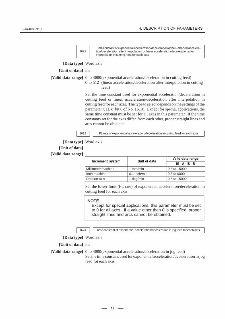
B–64160EN/01 4. DESCRIPTION OF PARAMETERS
53
1622Time constant of exponential acceleration/deceleration or bell–shaped accelera-tion/deceleration after interpolation, or linear aceeleration/deceleration afterinterpolation in cutting feed for each axis
[Data type] Word axis
[Unit of data] ms
[Valid data range] 0 to 4000(exponential acceleration/deceleration in cutting feed)0 to 512 (linear acceleration/deceleration after interpolation in cutting
feed)
Set the time constant used for exponential acceleration/deceleration incutting feed or linear acceleration/deceleration after interpolation incutting feed for each axis. The type to select depends on the settings of theparameter CTLx (bit 0 of No. 1610). Except for special applications, thesame time constant must be set for all axes in this parameter. If the timeconstants set for the axes differ from each other, proper straight lines andarcs cannot be obtained.
1623 FL rate of exponential acceleration/deceleration in cutting feed for each axis
[Data type] Word axis
[Unit of data][Valid data range]
��������� ������ ���� �� �������� ���� �����
��������� ������ ���� �� ����� !�" � !#
Millimeter machine 1 mm/min 0,6 to 15000
Inch machine 0.1 inch/min 0,6 to 6000
Rotaion axis 1 deg/min 0,6 to 15000
Set the lower limit (FL rate) of exponential acceleration/deceleration incutting feed for each axis.
NOTEExcept for special applications, this parameter must be setto 0 for all axes. If a value other than 0 is specified, properstraight lines and arcs cannot be obtained.
1624 Time constant of exponential acceleration/deceleration in jog feed for each axis.
[Data type] Word axis
[Unit of data] ms
[Valid data range] 0 to 4000(exponential acceleration/deceleration in jog feed)Set the time constant used for exponential acceleration/deceleration in jogfeed fot each axis.
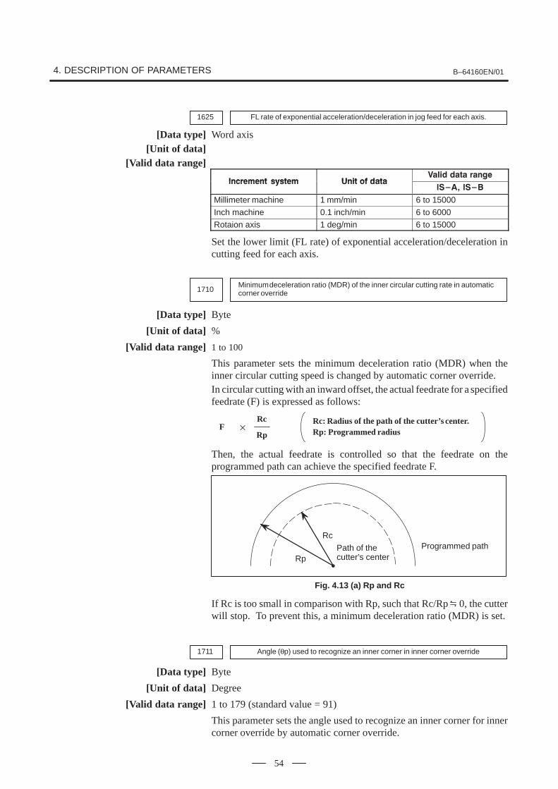
4. DESCRIPTION OF PARAMETERS B–64160EN/01
54
1625 FL rate of exponential acceleration/deceleration in jog feed for each axis.
[Data type] Word axis[Unit of data]
[Valid data range]
��������� ������ ���� �� �������� ���� �����
��������� ������ ���� �� ����� !�" � !#
Millimeter machine 1 mm/min 6 to 15000
Inch machine 0.1 inch/min 6 to 6000
Rotaion axis 1 deg/min 6 to 15000
Set the lower limit (FL rate) of exponential acceleration/deceleration incutting feed for each axis.
1710Minimum deceleration ratio (MDR) of the inner circular cutting rate in automaticcorner override
[Data type] Byte
[Unit of data] %
[Valid data range] 1 to 100
This parameter sets the minimum deceleration ratio (MDR) when theinner circular cutting speed is changed by automatic corner override.In circular cutting with an inward offset, the actual feedrate for a specifiedfeedrate (F) is expressed as follows:
Rc: Radius of the path of the cutter’s center.Rp: Programmed radius�F
Rc
Rp
Then, the actual feedrate is controlled so that the feedrate on theprogrammed path can achieve the specified feedrate F.
Rp
Rc
Path of thecutter’s center
Programmed path
Fig. 4.13 (a) Rp and Rc
If Rc is too small in comparison with Rp, such that Rc/Rp 0, the cutterwill stop. To prevent this, a minimum deceleration ratio (MDR) is set.
1711 Angle (θp) used to recognize an inner corner in inner corner override
[Data type] Byte
[Unit of data] Degree
[Valid data range] 1 to 179 (standard value = 91)
This parameter sets the angle used to recognize an inner corner for innercorner override by automatic corner override.
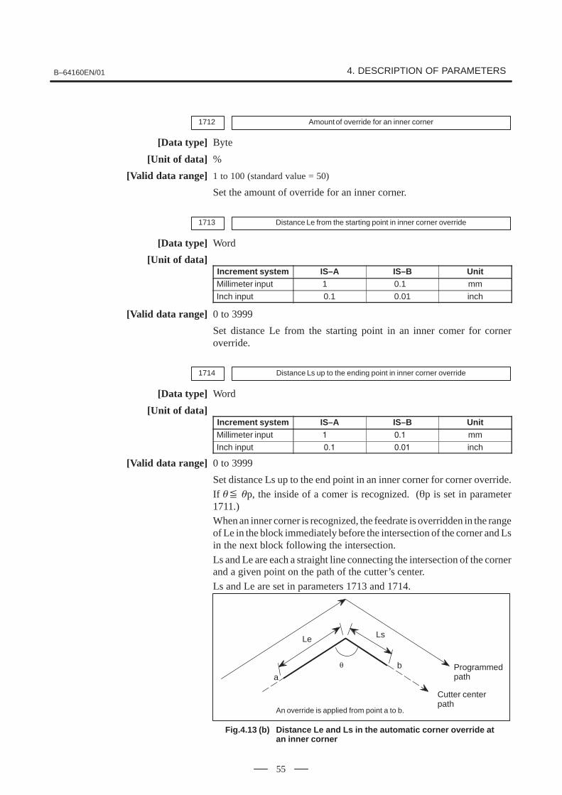
B–64160EN/01 4. DESCRIPTION OF PARAMETERS
55
1712 Amount of override for an inner corner
[Data type] Byte
[Unit of data] %
[Valid data range] 1 to 100 (standard value = 50)
Set the amount of override for an inner corner.
1713 Distance Le from the starting point in inner corner override
[Data type] Word
[Unit of data]Increment system IS–A IS–B UnitMillimeter input 1 0.1 mm
Inch input 0.1 0.01 inch
[Valid data range] 0 to 3999
Set distance Le from the starting point in an inner comer for corneroverride.
1714 Distance Ls up to the ending point in inner corner override
[Data type] Word
[Unit of data]Increment system IS–A IS–B UnitMillimeter input � �)� mm
Inch input �)� �)�� inch
[Valid data range] 0 to 3999
Set distance Ls up to the end point in an inner corner for corner override.
If �� �p, the inside of a comer is recognized. (�p is set in parameter1711.)When an inner corner is recognized, the feedrate is overridden in the rangeof Le in the block immediately before the intersection of the corner and Lsin the next block following the intersection.
Ls and Le are each a straight line connecting the intersection of the cornerand a given point on the path of the cutter’s center.
Ls and Le are set in parameters 1713 and 1714.
An override is applied from point a to b.
Programmedpath
Cutter centerpath
LsLe
abθ
Fig.4.13 (b) Distance Le and Ls in the automatic corner override at an inner corner

4. DESCRIPTION OF PARAMETERS B–64160EN/01
56
1722 Rapid traverse feedrate reduction ratio for overlapping rapid traverse blocks
[Data type] Byte axis
[Unit of data] %
[Valid data range] 1 to 100
This parameter is used when rapid traverse blocks are arrangedsuccessively, or when a rapid traverse block is followed by a block thatdoes not cause, movement. When the feedrate for each axis of a block isreduced to the ratio set in this parameter, the execution of the next block isstarted.
Fh
Fd
X–axis feedrate
N1 G00 X– – ; N2 G00 X– – ;
When the function of overlapping rapidtraverse blocks is enabled
When the function of overlapping rapidtraverse blocks is disabled
Fh�
Fd
: Rapid traverse feedrate: Setting of parameter No.1722 (feedrate reduction ratio): Feedrate where deceleration is terminated: Fh x �����
t
NOTEThe parameter No.1722 is effective when parameterNo.1601 #4 (RT0) is set to 1.
1730 Maximum feedrate for arc radius R
[Data type] Word
[Unit of data]
��������� ������ ���� �� �������� ���� �����
��������� ������ ���� �� ����� !�" � !#
Millimeter machine 1 mm/min 8 to 15000
Inch machine 0.1 inch/min 8 to 6000
Set a maximum feedrate for the arc radius set in parameter No.1731. Setthis parameter when the arc radius–based feedrate clamping function isenabled.
Examples

B–64160EN/01 4. DESCRIPTION OF PARAMETERS
57
1731 Arc radius value corresponding to a maximum feedrate
[Data type] 2–word
[Unit of data]Unit IS–A IS–B Unit
Linear axis (millimeter machine) 0.01 0.001 mm
Linear axis (inch machine) 0.001 0.0001 inch
[Valid data range] 1000 to 99999999
Set the arc radius corresponding to the maximum feedrate set in parameterNo.1730. Set this parameter when the arc radius–based feedrate clampingfunction is enabled.
1732 Minimum value (RV min) for arc radius–based feedrate clamp
[Data type] Word
��������� ������ ���� �� ����
���� ���� �����
��������� ������ ���� �� ����
� !�" � !#
Millimeter machine 1 mm/min 0 to 15000
Inch machine 0.1 inch/min 0 to 6000
The arc radius–based feedrate clamping function reduces the maximumfeedrate as the arc radius decreases. When the specified maximumfeedrate is not greater than RV min (minimum value for arc radius–basedfeedrate clamping), RV min is used as the maximum feedrate.
1762Exponential acceleration/deceleration time constant for cutting feed in the ad-vanced preview control mode
[Data type] Word axis
[Unit of data] 1 ms
[Valid data range] 0 to 4000
Set an exponential acceleration/deceleration time constant for cuttingfeed in the advanced preview control mode.
1763Minimum speed in exponential acceleration/deceleration for cutting feed in theadvanced preview control mode
[Data type] Word axis
��������� ������ ���� �� �������� ���� �����
��������� ������ ���� �� ����� !�" � !#
Millimeter machine 1 mm/min 6 to 15000
Inch machine 0.1 inch/min 6 to 6000
Rotation axis 1 deg/min 6 to 15000
Set minimum speed (FL) in exponential acceleration/deceleration forcutting feed in the advanced preview control mode.

4. DESCRIPTION OF PARAMETERS B–64160EN/01
58
1768Time constant for linear acceleration/deceleration after cutting feed interpolationduring advanced preview control mode.
[Data type] Word
[Unit of data] ms
[Valid data range] 8 to 512
This parameter sets a time constant for linear acceleration/decelerationafter cutting feed interpolation in the advanced preview control mode.Use parameter LS2 (No.1602#6) to select the acceleration/decelerationtype.
1770Parameter 1 (for advanced preview control) for setting an acceleration for linearacceleration/deceleration before interpolation (maximum machining speed dur-ing linear acceleration/deceleration before interpolation)
[Data type] 2–word
[Unit of data, valid range]
��������� ������ ���� �� �������� ���� �����
��������� ������ ���� �� ����� !�" � !#
Millimeter machine 1 mm/min 6 to 240000
Inch machine 0.1 inch/min 6 to 96000
This parameter is used to set an acceleration for linear acceleration/deceleration before interpolation in the advanced preview control mode.In this parameter, set the maximum machining speed during linearacceleration/ deceleration before interpolation. Set the time used to reachthe maximummachining speed in parameter No.1771.
Speed
Parameter 1(No.1770)
Parameter 2 (No.1771)Time
NOTEWhen 0 is set in parameter No.1770 or parameter No.1771,linear acceleration/deceleration before interpolation isdisabled.

B–64160EN/01 4. DESCRIPTION OF PARAMETERS
59
1771Parameter 2 (for advanced preview control) for setting an acceleration for linearacceleration/deceleration before interpolation (time used to reach the maximummachining speed during linear acceleration/deceleration before interpolation)
[Data type] Word
[Unit of data] 1 msec
[Valid range] 0 to 4000
This parameter is used to set an acceleration for linear acceleration/deceleration before interpolation in the advanced preview control mode.In this parameter, set the time (time constant) used toreach the speed set inparameter No.1770.
NOTE1 When 0 is set in parameter No.1770 or parameter No.1771,
linear acceleration/deceleration before interpolation isdisabled.
2 In parameter Nos. 1770 and 1771, set values that satisfy thefollowing:Parameter No.1770/Parameter No.1771 � 5
1777Minimum speed for the automatic corner deceleration function (advanced pre-view control)
[Data type] Word
[Unit of data, valid range]
��������� ������ ���� �� �������� ���� �����
��������� ������ ���� �� ����� !�" � !#
Millimeter machine 1 mm/min 6 to 15000
Inch machine 0.1 inch/min 6 to 6000
Set a speed at which the number of buffered pulses in deceleration isassumed to be 0 when linear acceleration/deceleration beforeinterpolation is used.
1779Critical angle subtended by two blocks for automatic corner deceleration (foradvanced preview control)
[Data type] 2–word
[Unit of data] 0.001 deg
[Valid data range] 0 to 180000
Set a critical angle to be subtended by two blocks for corner decelerationwhen the angle–basedautomatic corner deceleration function is used.
The angle subtended by two blocks is defined as θ in the examples shownbelow.

4. DESCRIPTION OF PARAMETERS B–64160EN/01
60
θ θ
Block A (G01)
Block B (G01)
Angle subtended by two straight lines
Block A (G02)
Block B (G01)
Angle subtended by an arc and its tangent
1780Allowable speed difference for the speed difference–based corner decelerationfunction (for advanced preview control)
[Data type] Word
[Unit of data, valid range]
��������� ������ ���� �� �������� �����
��������� ������ ���� �� ����� !�" � !#
Millimeter machine 1 mm/min 6 to 15000
Inch machine 0.1 inch/min 6 to 6000
Set the speed difference for the speed difference–based automatic cornerdeceleration function when linear acceleration/deceleration beforeinterpolation is used.
1783Allowable speed difference for the speed difference based corner decelerationfunction (for advanced preview control)
[Data type] Word axis
[Unit of data, valid range]
��������� ������ ���� �� �������� �����
��������� ������ ���� �� ����� !�" � !#
Millimeter machine 1 mm/min 6 to 15000
Inch machine 0.1 inch/min 6 to 6000
Rotation axis 1 deg/min 6 to 15000
A separate allowable feedrate difference can be set for each axis. Theallowable feedrate difference is set for each axis with this parameter.Among the axes that exeed the specified allowable feedrate difference, theaxis with the greatest ratio of the actual feedrate difference to theallowable feedrate difference is used as the reference to calculate thereduced feedrate at the corner.

B–64160EN/01 4. DESCRIPTION OF PARAMETERS
61
1784Speed when overtravel alarm has generated during acceleration/decelerationbefore interpolation (for advanced preview control)
[Data type] Word axis
[Unit of data][Valid data range]
��������� ������ ���� �� �������� �����
��������� ������ ���� �� ����� !�" � !#
Millimeter machine 1 mm/min 6 to 15000
Inch machine 0.1 inch/min 6 to 6000
Rotation axis 1 deg/min 6 to 15000
Deceleration is started beforehand to reach the feedrate set in theparameter when an overtravel alarm is issued (when a limit is reached)during linear acceleration/deceleration before interpolation. By usingthis parameter, the overrun distance that occurs when an overtravel alarmis output can be reduced.
NOTE1 When 0 is set in this parameter, the control described above
is not exercised.2 Use type–B linear acceleration/deceleration before
interpolation (by setting bit 0 (FWB) of parameter No.1602to 1).
3 The control described above is applicable only to storedstroke check 1.

4. DESCRIPTION OF PARAMETERS B–64160EN/01
62
#71800
#6 #5 #4RBK
#3FFR
#2OZR
#1CVR
#0
[Data type] Bit
CVR When velocity control ready signal VRDY is set ON before positioncontrol ready signal PRDY comes ON0: A servo alarm is generated.1: A servo alarm is not generated.
OZR When manual reference position return is attempted in the halt stateduring automatic operation (feed hold stop state) under any of theconditions listed below:0: Manual reference position return is not performed, with P/S alarm
No.091.1: Manual reference position return is performed without an alarm
occurring.
< Conditions >
(1) When there is a remaining distance to travel.
(2) When an auxiliary function (miscellaneous function, spindle–speedfunction, tool function) is being executed.
(3) When a cycle such as a dwell cycle or canned cycle is being executed.
FFR Feed–forward control is enabled for0 : Cutting feed only1 : Cutting feed and rapid traverse
RBK Backlash compensation applied separately for cutting feed and rapidtraverse0: Not performed1: Performed
#7
1801
#6 #5CIN
#4CCI
#3API
#2 #1 #0
[Data type] Bit
API To use an absolute position detector for any axis, set API to 1.
CCI The in–position area for cutting feed is:0 : Set in parameter No.1826 (same as for rapid traverse).1 : Set in bit 5 (CIN) of parameter No.1801.
CIN When bit 4 (CCI) of parameter No.1801 = 1, the in–position area forcutting feed is:0 : Use value in parameter No.1827 if the next block is also for cutting
feed, or use value in parameter No.1826 if the next block is not forcutting feed.
1 : Use value in parameter No.1827, regardless of the next block. (Thesetting of parameter No.1826 is used for rapid traverse, and the settingof parameter No.1827 is used for cutting feed.)
4.14PARAMETERS OF SERVO

B–64160EN/01 4. DESCRIPTION OF PARAMETERS
63
#71804
#6SAK
#5ANA
#4IVO
#3 #2 #1 #0
[Data type] Bit axis
IVO When an attempt is made to release an emergency stop while the VRDYOFF alarm ignore signal is 1:0 : The emergency stop state is not released until the VRDY OFF alarm
ignore signal is set to 0.1 : The emergency stop state is released.
NOTEWhen a reset is issued while the VRDY OFF alarm ignoresignal is set to 1 and the motor activating current is low, thereset state can also be released, provided this parameter isset to 1.
ANA When an abnormal load is detected for an axis:0 : Movement along all axes is stopped, and a servo alarm is output.1 : No servo alarm is output, and movement along only the axes of the
group containing the axis with the abnormal load is stopped in interlockmode. (The group number of each axis is set in parameter No.1881.)
SAK When the VRDY OFF alarm ignore signal IGNVRY is 1, or when theVRDY OFF alarm ignore signals IGVRY1 to IGVRY4 are 1:0 : Servo ready signal SA is set to 0.1 : Servo ready signal SA remains set to 1.
#71815
#6 #5APCx
#4APZx
#3 #2 #1OPTx
#0
NOTEWhen this parameter has been set, the power must beturned off before operation is continued.
[Data type] Bit axisOPTx Position detector
0 : A separate pulse coder is not used.1 : A separate pulse coder is used.
For an absolute–position system using Inductosyn, set this parameter to 1.APZx Machine position and position on absolute position detector when the
absolute position detector is used0 : Not corresponding1 : Corresponding
NOTEWhen an absolute position detector is used, after primaryadjustment is performed or after the absolute positiondetector is replaced, this parameter must be set to 0, powermust be turned off and on, then manual reference positionreturn must be performed. This completes the positionalcorrespondence between the machine position and theposition on the absolute position detector, and sets thisparameter to 1 automatically.

4. DESCRIPTION OF PARAMETERS B–64160EN/01
64
APCx Position detector0 : Other than absolute position detector1 : Absolute position detector (absolute pulse coder)
For an absolute–position system using Inductosyn, set this parameter to 1.
#71817
#6TANx
#5 #4SCPx
#3 #2 #1 #0
NOTEWhen this parameter has been set, the power must beturned off before operation is continued.
[Data type] Bit axis
SCPx If bit 2 (DC2) of parameter No. 1802 is set to 1, the scale zero point of thelinear scale with absolute addressing reference marks is:0: On the negative direction side. (Viewed from the scale zero point, the
reference position is on the positive direction side.)1: On the positive direction side. (Viewed from the scale zero point, the
reference position is on the negative direction side.)
TANx Tandem control0 : Not used1 : Used
NOTESet this parameter to both master axis and slave axis.
#7
1819
#6 #5 #4 #3 #2 #1CRFx
#0FUPx
[Data type] Bit axis
FUPx To perform follow–up when the servo is off is set for each axis.0: The follow–up signal, *FLWU, determines whether follow–up is
performed or not.When *FLWU is 0, follow–up is performed.When *FLWU is 1, follow–up is not performed.
1: Follow–up is not performed.
NOTEWhen the index table indexing function (M series) is used,be sure to set FUPx of the 4th axis to 1.
CRFx When servo alarm No.445 (software disconnection), No.446 (hardwaredisconnection), No.447 (hardware disconnection (separate type)), orNo.421 (excessive dual position feedback error) is issued:0 : The reference position setting remains as is.1 : The system enters the reference position undefined state.
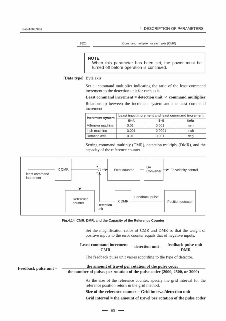
B–64160EN/01 4. DESCRIPTION OF PARAMETERS
65
1820 Command multiplier for each axis (CMR)
NOTEWhen this parameter has been set, the power must beturned off before operation is continued.
[Data type] Byte axis
Set a command multiplier indicating the ratio of the least commandincrement to the detection unit for each axis.
Least command increment = detection unit � command multiplier
Relationship between the increment system and the least commandincrement
Increment systemLeast input increment and least command increment
Increment systemIS–A IS–B Units
Millimeter machine 0.01 0.001 mm
Inch machine 0.001 0.0001 inch
Rotation axis 0.01 0.001 deg
Setting command multiply (CMR), detection multiply (DMR), and thecapacity of the reference counter
least commandincrement
X CMR Error counter
X DMRReferencecounter
DAConverter
Position detector
To velocity control
Feedback pulse
Detectionunit
+
–
Fig.4.14 CMR, DMR, and the Capacity of the Reference Counter
Set the magnification ratios of CMR and DMR so that the weight ofpositive inputs to the error counter equals that of negative inputs.
feedback pulse unitLeast command incrementCMR
=detection unit=DMR
The feedback pulse unit varies according to the type of detector.
Feedback pulse unit = the amount of travel per rotation of the pulse coderthe number of pulses per rotation of the pulse coder (2000, 2500, or 3000)
As the size of the reference counter, specify the grid interval for thereference position return in the grid method.
Size of the reference counter = Grid interval/detection unit
Grid interval = the amount of travel per rotation of the pulse coder

4. DESCRIPTION OF PARAMETERS B–64160EN/01
66
The value set in the parameter is obtained as follows:
(1) When command multiplier is 1/2 to 1/27
Set value = 1(Command multiplier)
+ 100
Valid data range: 102 to 127
(2) When command multiply is 1 to 48Set value = 2 command multiplierValid data range: 2 to 96
NOTEWhen command multiplier is 1 to 48, the set value must bedetermined so that an integer can be set for commandmultiplier.
1821 Reference counter size for each axis
NOTEWhen this parameter has been set, the power must beturned off before operation is continued.
[Data type] 2–word axis
[Valid data range] 0 to 99999999
Set the size of the reference counter.
1825 Servo loop gain for each axis
[Data type] Word axis
[Unit of data] 0.01 s –1
[Valid data range] 1 to 9999
Set the loop gain for position control for each axis.
When the machine performs linear and circular interpolation (cutting), thesame value must be set for all axes. When the machine requirespositioning only, the values set for the axes may differ from one another.As the loop gain increases, the response by position control is improved.A too large loop gain, however, makes the servo system unstable.
The relationship between the positioning deviation (the number of pulsescounted by the error counter) and the feedrate is expressed as follows:
feedrate�
Positioning deviation =60 (loop gain)
Unit : Positioning deviation mm, inches, or degFeedrate : mm/min, inches/min, or deg/minloop gain: s–1

B–64160EN/01 4. DESCRIPTION OF PARAMETERS
67
1826 In–position width for each axis
[Data type] Word axis
[Unit of data] Detection unit
[Valid data range] 0 to 32767
The in–position width is set for each axis.When the deviation of the machine position from the specified position(the absolute value of the positioning deviation) is smaller than thein–position width, the machine is assumed to have reached the specifiedposition. (The machine is in the in–position state.)
1827 In–position width in cutting feed for each axis
[Data type] Word axis
[Unit of data] Detection unit
[Valid data range] 0 to 32767
Set an in–position width for each axis in cutting feed. This parameter isvalid when bit 4 (CCI) of parameter No.1801=1.
1828 Positioning deviation limit for each axis in movement
[Data type] 2–word axis
[Unit of data] Detection unit
[Valid data range] 0 to 99999999
Set the positioning deviation limit in movement for each axis.If the positioning deviation exceeds the positioning deviation limit duringmovement, a servo alarm is generated, and operation is stoppedimmediately (as in emergency stop).Generally, set the positioning deviation for rapid traverse plus somemargin in this parameter.
1829 Positioning deviation limit for each axis in the stopped state
[Data type] Word axis
[Unit of data] Detection unit
[Valid data range] 0 to 32767
Set the positioning deviation limit in the stopped state for each axis.If, in the stopped state, the positioning deviation exceeds the positioningdeviation limit set for stopped state, a servo alarm is generated, andoperation is stopped immediately (as in emergency stop).
1830 Axis–by–axis positional deviation limit at servo–off time
[Data type] 2–word axis
[Unit of data] Detection unit
[Valid data range] 0 to 99999999
This parameter is used to set a positional deviation limit at servo–off time,on an axis–by–axis basis.
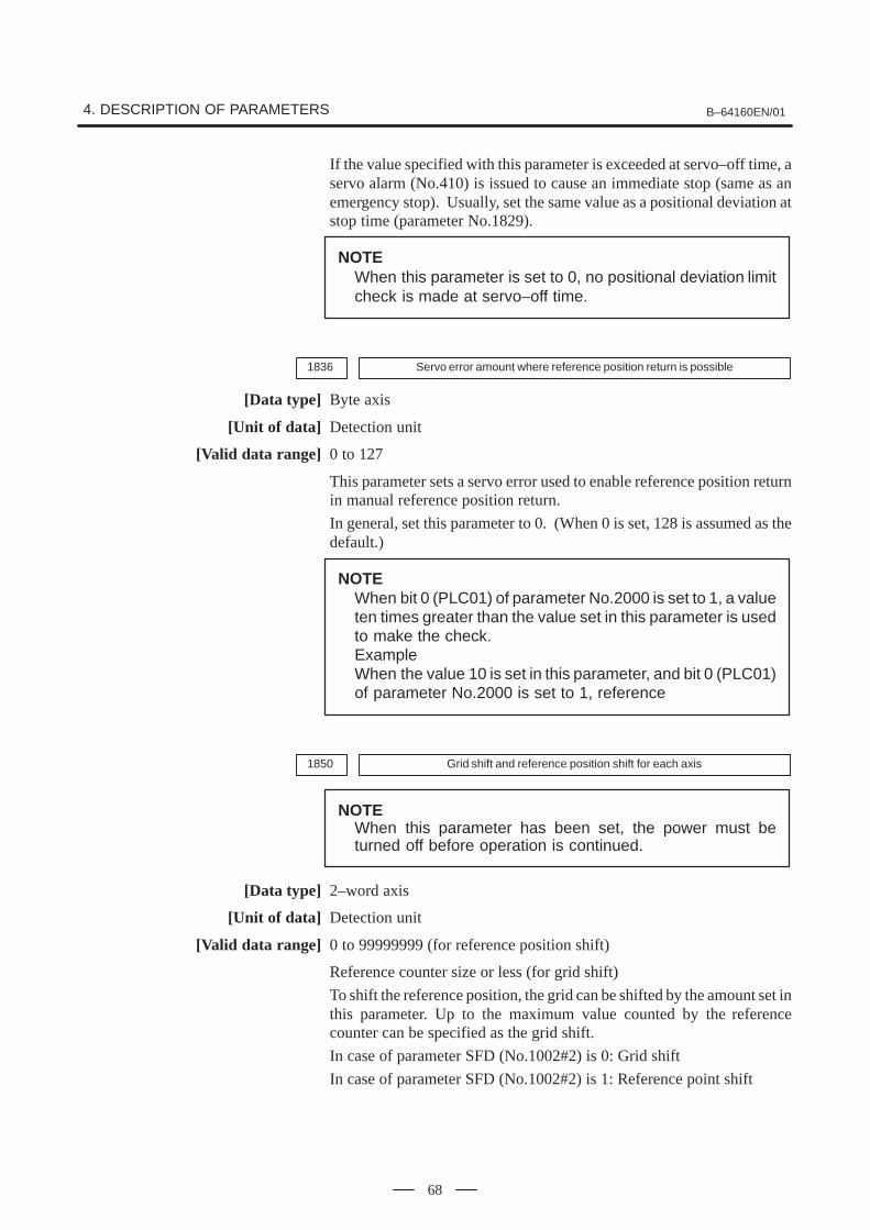
4. DESCRIPTION OF PARAMETERS B–64160EN/01
68
If the value specified with this parameter is exceeded at servo–off time, aservo alarm (No.410) is issued to cause an immediate stop (same as anemergency stop). Usually, set the same value as a positional deviation atstop time (parameter No.1829).
NOTEWhen this parameter is set to 0, no positional deviation limitcheck is made at servo–off time.
1836 Servo error amount where reference position return is possible
[Data type] Byte axis
[Unit of data] Detection unit
[Valid data range] 0 to 127
This parameter sets a servo error used to enable reference position returnin manual reference position return.
In general, set this parameter to 0. (When 0 is set, 128 is assumed as thedefault.)
NOTEWhen bit 0 (PLC01) of parameter No.2000 is set to 1, a valueten times greater than the value set in this parameter is usedto make the check.ExampleWhen the value 10 is set in this parameter, and bit 0 (PLC01)of parameter No.2000 is set to 1, reference
1850 Grid shift and reference position shift for each axis
NOTEWhen this parameter has been set, the power must beturned off before operation is continued.
[Data type] 2–word axis
[Unit of data] Detection unit
[Valid data range] 0 to 99999999 (for reference position shift)
Reference counter size or less (for grid shift)
To shift the reference position, the grid can be shifted by the amount set inthis parameter. Up to the maximum value counted by the referencecounter can be specified as the grid shift.
In case of parameter SFD (No.1002#2) is 0: Grid shift
In case of parameter SFD (No.1002#2) is 1: Reference point shift
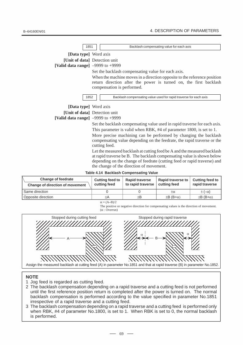
B–64160EN/01 4. DESCRIPTION OF PARAMETERS
69
1851 Backlash compensating value for each axis
[Data type] Word axis[Unit of data] Detection unit
[Valid data range] –9999 to +9999Set the backlash compensating value for each axis.When the machine moves in a direction opposite to the reference positionreturn direction after the power is turned on, the first backlashcompensation is performed.
1852 Backlash compensating value used for rapid traverse for each axis
[Data type] Word axis[Unit of data] Detection unit
[Valid data range] –9999 to +9999Set the backlash compensating value used in rapid traverse for each axis.This parameter is valid when RBK, #4 of parameter 1800, is set to 1.More precise machining can be performed by changing the backlashcompensating value depending on the feedrate, the rapid traverse or thecutting feed.Let the measured backlash at cutting feed be A and the measured backlashat rapid traverse be B. The backlash compensating value is shown belowdepending on the change of feedrate (cutting feed or rapid traverse) andthe change of the direction of movement.
Table 4.14 Backlash Compensating Value
Change of feedrate
Change of direction of movementCutting feed tocutting feed
Rapid traverseto rapid traverse
Rapid traverse tocutting feed
Cutting feed torapid traverse
Same direction 0 0 ±α ± (–α)
Opposite direction ±A ±B ±B (B+α) ±B (B+α)α = (A–B)/2The positive or negative direction for compensating values is the direction of movement.(α : Overrun)
ÉÉÉÉÉÉÉÉÉÉÉÉÉÉÉÉÉÉÉÉÉÉÉÉÉÉÉÉÉÉÉÉÉÉÉÉÉÉÉÉÉÉÉÉÉÉÉÉÉÉÉÉÉÉÉÉÉÉÉÉÉÉÉÉÉ
ÇÇÇÇÇÇÇÇÇÇÇÇÇÇÇÇÇÇÇÇÇÇÇÇÇÇÇÇÇÇÇÇÇÇÇÇÇÇÇÇÇÇÇÇÇÇÇÇÇÇÇÇÇÇÇÇÇÇÇÇÇÇÇÇÇÇÇÇÇÇÇÇÇÇÇÇÇÇ
ÉÉÉÉÉÉÉÉÉÉÉÉÉÉÉÉÉÉÉÉÉÉÉÉÉÉÉÉÉÉÉÉÉÉÉÉÉÉÉÉÉÉÉÉÉÉÉÉÉÉÉÉÉÉÉÉÉÉÉÉÉÉÉÉÉ
ÇÇÇÇÇÇÇÇÇÇÇÇÇÇÇÇÇÇÇÇÇÇÇÇÇÇÇÇÇÇÇÇÇÇÇÇÇÇÇÇÇÇÇÇÇÇÇÇÇÇÇÇÇÇÇÇÇÇÇÇÇÇÇÇÇÇÇÇÇÇÇÇÇÇÇÇÇÇ
� �
A B
Stopped during cutting feed Stopped during rapid traverse
Assign the measured backlash at cutting feed (A) in parameter No.1851 and that at rapid traverse (B) in parameter No.1852.
NOTE1 Jog feed is regarded as cutting feed.2 The backlash compensation depending on a rapid traverse and a cutting feed is not performed
until the first reference position return is completed after the power is turned on. The normalbacklash compensation is performed according to the value specified in parameter No.1851irrespective of a rapid traverse and a cutting feed.
3 The backlash compensation depending on a rapid traverse and a cutting feed is performed onlywhen RBK, #4 of parameter No.1800, is set to 1. When RBK is set to 0, the normal backlashis performed.

4. DESCRIPTION OF PARAMETERS B–64160EN/01
70
1874 Number of the conversion coefficient for inductosyn position detection
1875 Denominator of the conversion coefficient for inductosyn position detection
NOTEWhen this parameter has been set, the power must beturned off before operation is continued.
[Data type] Word axis
[Valid data range] 1 to 32767
Set a conversion coefficient for inductosyn position detection for eachaxis. The value set is determined as follows:
=Number of position feedback pulses per motor revolution1,000,000
No. 1874No. 1875
1876 One–pitch interval of the inductosyn
NOTEWhen this parameter has been set, the power must beturned off before operation is continued.
[Data type] Word axis
[Unit of data] Detection unit
[Valid data range] 1 to 32767
Set a one–pitch interval of the inductosyn for each axis.
SUPPLEMENTAL REMARKTo use an absolute–position detector using Inductosyn, setthe following digital servo parameters as well:
Bit 4 (INDx) of parameter No. 2015The absolute–position detect function by Inductosyn is:0 : Disabled.1 : Enabled.
Parameter No. 2141 Inductosyn data acquisition timeSet a time requirement for acquiring theInductosyn data. If the setting is 0, 20 ms isassumed. (For the setting, contact the scalemanufacturer.)

B–64160EN/01 4. DESCRIPTION OF PARAMETERS
71
1880 Abnormal load detection alarm timer
[Data type] Word axis
[Unit of data] ms
[Valid data range] 0 to 32767 (200 mse is assumed when 0 is set)
This parameter sets the time from the detection of an abnormal load until aservo alarm is issued. The specified value is rounded up to the nearestintegral multiple of 8 msec.
[Example] When 30 is specified, the value is rounded up to 32 (msec).
1881 Group number when an abnormal load is detected
[Data type] Byte axis
[Valid data range] 0 to 4
This parameter sets the group number of each axis, used when anabnormal load is detected.
If an abnormal load is detected for an axis, only the movement along theaxes of the group containing the axis with the abnormal load is stopped. If0 is set for an axis, movement along that axis is stopped whenever anabnormal load is detected for any axis.
Example: Assume that the following settings have been made. If anabnormal load is detected for the first axis, movement alongthe first, third, and fourth axes is stopped. If an abnormal loadis detected for the second axis, movement along the secondand fourth axes is stopped.
Parameter No.1881 Setting(First axis) 1
(Second axis) 2(Third axis) 1
(Fourth axis) 0
NOTEThis parameter is enabled when the ANA parameter (bit 5 ofparameter No.1804) is 1.

4. DESCRIPTION OF PARAMETERS B–64160EN/01
72
#71902
#6 #5 #4 #3 #2 #1ASE
#0FMD
NOTEAfter this parameter has been set, the power must be turnedoff then back on for the setting to become effective.
[Data type] Bit
FMD The FSSB setting mode is:0 : Automatic setting mode.
(When information including an axis–amplifier relationship is set onthe FSSB setting screen, parameter Nos. 1023, 1905, 1910 through1919, 1936, and 1937 are set automatically.)
1 : Manual setting 2 mode.(Set parameter Nos. 1023, 1905, 1910 through 1919, 1936, and 1937manually.)
ASE When automatic setting mode is selected for FSSB setting (when the FMDparameter (bit 0 of parameter No.1902) is set to 0), automatic setting is:0 : Not completed.1 : Completed.
(This bit is automatically set to 1 upon the completion of automaticsetting.)
#71904
#6 #5 #4 #3 #2 #1 #0DSP
NOTEAfter this parameter has been set, the power must be turnedoff then back on for the setting to become effective.
[Data type] Bit axis
DSP0 : Two axes use one DSP. (Ordinary axes)1 : One axis uses one DSP.
NOTEParameter No.1904 is set on the FSSB setting screen. So,parameter No.1904 should not have to be specified directly.This parameter need not be set in FSSB manual setting 2mode.

B–64160EN/01 4. DESCRIPTION OF PARAMETERS
73
#7PM21905
#6PM1
#5IO2
#4IO1
#3 #2 #1 #0FSL
NOTEAfter this parameter has been set, the power must be turnedoff then back on for the setting to become effective.
[Data type] Bit axis
FSL The type of interface used between the servo amplifier and servo software is:0 : Fast type.1 : Slow type.
The user can choose between two interface types for servo data transfer:fast type or slow type. Set this parameter so that the following conditionsare satisfied:
� When a one–axis amplifier is used, either the fast type or slow typeinterface can be used.
� When a two–axis amplifier is used, the use of the fast type for both axesis not allowed. The slow type can be used for both axes.
� When a three–axis amplifier is used, the requirement for a two–axesamplifier described above applies to the first and second axes, and therequirement for a one–axis amplifier, again described above, applies tothe third axis.
� When an odd number is specified for parameter No.1023, the fast typeinterface must be used. However, the slow type may be used for high–speed current loop axis and high–speed interface axis.
� When an even number is specified for parameter No.1023, only theslow type interface can be used. (The FSL bit must always be set to 1.)
Controlledaxis
number
1234
Programaxis nameNo.1020
XYZA
Servo axis numberNo.1023
1234
Interfacetype
Fast/Slow
FFSS
CNC
2–axisamplifier
1–axisamplifier
X (Fast)
A (Slow)
Y (Fast)
Z (Slow)1–axisamplifier
IO1 A first I/O module supporting FSSB is:0 : Not used.1 Used.
IO2 A second I/O module supporting FSSB is:0 : Not used.1 Used.
PM1 The first separate detecter interface unit is:0 : Not used.1 : Used.
4. DESCRIPTION OF PARAMETERS B–64160EN/01
74
PM2 The second separate detecter interface unit is:0 : Not used.1 : Used.
NOTEWhen automatic setting mode is selected for FSSB setting(when the FMD parameter (bit 0 of parameter No.1902) is setto 0), parameter No.1905 is automatically set when input isperformed with the FSSB setting screen. When manualsetting 2 mode is selected for FSSB setting (when the FMDparameter (bit 0 of parameter No.1902) is set to 1),parameter No.1905 must be set directly. When a separatedetecter interface unit is used, a connector number must beset in the corresponding parameter (No.1936 or No.1937).

B–64160EN/01 4. DESCRIPTION OF PARAMETERS
75
1910 Address conversion table value for slave 1 (ATR)
1911 Address conversion table value for slave 2 (ATR)
1912 Address conversion table value for slave 3 (ATR)
1913 Address conversion table value for slave 4 (ATR)
1914 Address conversion table value for slave 5 (ATR)
1915 Address conversion table value for slave 6 (ATR)
1916 Address conversion table value for slave 7 (ATR)
1917 Address conversion table value for slave 8 (ATR)
1918 Address conversion table value for slave 9 (ATR)
1919 Address conversion table value for slave 10 (ATR)
NOTEAfter these parameters have been set, the power must beturned off then back on for the settings to become effective.
[Data type] Byte
[Valid data range] 0 to 3, 16, 40, 48
These parameters set address conversion table values for slaves 1 to 10.
A slave is the generic name given to a device such as a servo amplifier orseparate detecter interface unit, connected to the CNC via an FSSB opticalcable. Smaller numbers, starting from 1 are assigned to slaves closer tothe CNC; the maximum number that can be assigned is 10. A two–axisamplifier has two slaves, while a three–axis amplifier has three slaves. Seteach parameter as described below, depending on whether the slave is anamplifier or separate detecter interface unit, or when no slave exists.
� When the slave is an amplifier:Set the value obtained by subtracting 1 from the setting of parameterNo.1023 for the axis to which the amplifier is assigned.
� When the slave is a separate detecter interface unit:Set 16 for the first separate detecter interface unit (closest to the CNC).Set 48 for the second separate detecter interface unit (furthest from theCNC).
� When no slave existsSet 40.
NOTEWhen automatic setting mode is selected for FSSB setting(when the FMD parameter (bit 0 of parameter No.1902) isset to 0), parameters No.1910 through No.1919 areautomatically set when input is performed with the FSSBsetting screen. When manual setting mode is selected forFSSB setting (when the FMD parameter (bit 0 of parameterNo.1902) is set to 1), parameter No.1910 through No.1919must be directly set.
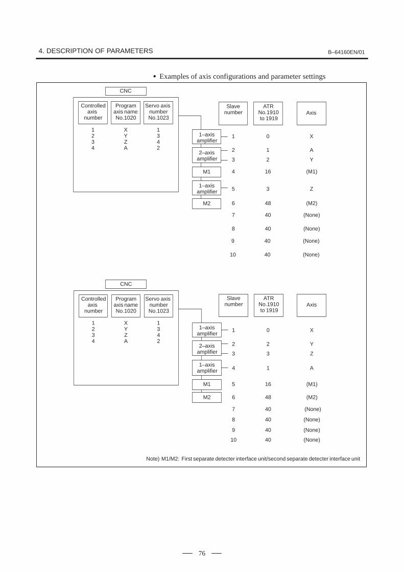
4. DESCRIPTION OF PARAMETERS B–64160EN/01
76
� Examples of axis configurations and parameter settings
CNC
2–axisamplifier
M1
2
3
4
5
M2 6
1–axisamplifier
1
Slavenumber
ATRNo.1910 to 1919
Axis
1
2
16
3
48
0
A
Y
(M1)
Z
(M2)
X
7
8
40
40
(None)
(None)
Controlledaxis
number
1234
Programaxis nameNo.1020
XYZA
Servo axis numberNo.1023
1342
1–axisamplifier
9
10
40
40
(None)
(None)
M1
2
3
5
4
M2 6
7
1
2
3
16
1
48
40
0
Y
Z
(M1)
A
(M2)
(None)
X
8
9
40
40
(None)
(None)
Note) M1/M2: First separate detecter interface unit/second separate detecter interface unit
CNC
Controlledaxis
number
1234
Programaxis nameNo.1020
XYZA
Servo axis numberNo.1023
1342
Slavenumber
ATRNo.1910 to 1919
Axis
2–axisamplifier
1–axisamplifier
1–axisamplifier
10 40 (None)

B–64160EN/01 4. DESCRIPTION OF PARAMETERS
77
1920 Controlled axis number for slave 1 (dedicated to the FSSB setting screen)
1921 Controlled axis number for slave 2 (dedicated to the FSSB setting screen)
1922 Controlled axis number for slave 3 (dedicated to the FSSB setting screen)
1923 Controlled axis number for slave 4 (dedicated to the FSSB setting screen)
1924 Controlled axis number for slave 5 (dedicated to the FSSB setting screen)
1925 Controlled axis number for slave 6 (dedicated to the FSSB setting screen)
1926 Controlled axis number for slave 7 (dedicated to the FSSB setting screen)
1927 Controlled axis number for slave 8 (dedicated to the FSSB setting screen)
1928 Controlled axis number for slave 9 (dedicated to the FSSB setting screen)
1929 Controlled axis number for slave 10 (dedicated to the FSSB setting screen)
NOTEAfter these parameters have been set, the power must beturned off then back on for the settings to become effective.
[Data type] Byte
[Valid data range] 0 to 3
These parameters are used to set the controlled axis numbers for slaves 1to 10.
NOTEThese parameters are set using the FSSB setting screen.So, these parameters should not normally have to bespecified directly. These parameters need not be set inFSSB manual setting mode.
1931Connector number for the first separate detecter interface unit (dedicated to theFSSB setting screen)
1932Connector number for the second separate detecter interface unit (dedicated to theFSSB setting screen)
NOTEAfter these parameters have been set, the power must beturned off then back on for the settings to become effective.
[Data type] Byte axis
[Valid data range] 0 to number of connectors provided on each separate detecter interface unit
When a separate detecter interface unit is used, these parameters set aseparate detecter interface unit connector number for each axis.
NOTEThese parameters are set using the FSSB setting screen.So, these parameters should not normally have to bespecified directly. These parameters need not be set inFSSB manual setting 2 mode.

4. DESCRIPTION OF PARAMETERS B–64160EN/01
78
1934Master and slave axis numbers subject to tandem control
(dedicated to the FSSB setting screen)
NOTEAfter this parameter has been set, the power must be turnedoff then back on for the setting to become effective.
[Data type] Byte axis
[Valid data range] 0 to 8
This parameter is used to set an odd number, and the subsequent evennumber, for a master axis and slave axis subject to tandem control,respectively.
NOTEThis parameter is set using the FSSB setting screen. So,this parameter should not normally have to be specifieddirectly. This parameter need not be set in FSSB manualsetting 2 mode.
1936 Connector number of the first separate detecter interface unit
1937 Connector number of the second separate detecter interface unit
NOTEAfter these parameters have been set, the power must beturned off then back on for the settings to become effective.
[Data type] Byte axis
[Valid data range] 0 to 7
When a separate detecter interface unit is used, each of these parameterssets the value obtained by subtracting 1 from a separate detecter interfaceunit connector number for each axis. That is, values of 0 through 7 are setfor connector numbers 1 through 8. In addition, bits 6 and 7 of parameterNo.1905 must be set. For an axis that does not use a separate detecterinterface unit, 0 must be set.
Any connector can be used for any axis, however the connectors in asingle separate detecter interface unit should be used in ascending order ofconnector number. For instance, connector 4 of a separate detecterinterface unit cannot be used without using connector 3 of the sameseparate detecter interface unit.

B–64160EN/01 4. DESCRIPTION OF PARAMETERS
79
Example:
Controlledaxis
Connectornumber for
the first separate detecter
interface unit
Connectornumber forthe second
separate detecter
interface unit
No.1936 No.1937 No.1905(#7, #6)
X 1 Not used 0 0 0,1
Y Not used 2 0 1 1,0
Z Not used 1 0 0 1,0
A Not used Not used 0 0 0,0
NOTEWhen automatic setting mode is selected for FSSB setting(when bit 0 of parameter No.1902 is set to 0), theseparameters are automatically set when input is performedwith the FSSB setting screen. When manual setting 2 modeis selected for FSSB setting (when bit 0 of parameterNo.1902 is set to 1), these parameters must be set directly.

4. DESCRIPTION OF PARAMETERS B–64160EN/01
80
Parameters No.2000 to 2999 are for digital servo, The following parameters are not explained in this manual.Refer to FANUC AC SERVO MOTOR αi series PARAMETER MANUAL (B–65270EN)
No. Data type Contents
2000 Bit axis PGEX PRMC DGPR PLC0
2001 Bit axis AMR7 AMR6 AMR5 AMR4 AMR3 AMR2 AMR1 AMR0
2002 Bit axis VFSE PFSE
2003 Bit axis V0FS OVSC BLEN NPSP PIEN OBEN TGAL
2004 Bit axis DLY0 TRW1 TRW0 TIB0 TIA0
2005 Bit axis SFCM BRKC FEED
2006 Bit axis DCBE ACCF SPVE PKVE SBSM FCBL
2007 Bit axis FRCA FAD
2008 Bit axis LAXD PFBS VCTM SPPC SPPR VFBA TNDM
2009 Bit axis BLST BLCU ADBL IQOB SERD
2010 Bit axis POLE HBBL HBPE BLTE LINE
2011 Bit axis RCCL FFALWY SYNMOD
2012 Bit axis STNG VCM2 VCM1 MSFE
2013 Bit axis APTG
2014 Bit axis (Reserve)
2015 Bit axis BZNG BLAT TDOU SSG1 PGTW
2016 Bit axis K2VC ABNT
2017 Bit axis PK25 OVCR RISC HTNG DBST
2018 Bit axis PFBC MOVO REVS
2019 Bit axis DPFB SPSY
2020 Word axis Motor number
2021 Word axis Load inertia ratio
2022 Word axis Direction of motor rotation
2023 Word axis Number of velocity pulses
2024 Word axis Number of position pulses
2028 Word axis Position gain switching speed
2029 Word axis Effective speed for integral acceleration at low speed
2030 Word axis Effective speed for integral deceleration at low speed
2033 Word axis Position feedback pulse
2034 Word axis Damping control gain
2039 Word axis Second–stage acceleration for two–stage backlash acceleration
2040 Word axis Current loop integral gain (PK1)
2041 Word axis Current loop proportional gain (PK2)
2042 Word axis Current loop gain (PK3)
2043 Word axis Velocity loop integral gain (PK1V)
2044 Word axis Velocity loop proportional gain (PK2V)
2045 Word axis Velocity loop incomplete integral gain (PK3V)
2046 Word axis Velocity loop gain (PK4V)
2047 Word axis Observer parameter (POA1)
2048 Word axis Backlash acceleration
2049 Word axis Maximum amplitude for dual position feedback
2050 Word axis Observer parameter (POK1)
2051 Word axis Observer parameter (POK2)
2053 Word axis Current dead zone compensation (PPMAX)
2054 Word axis Current dead zone compensation (PDDP)
2055 Word axis Current dead zone compensation (PHYST)
2056 Word axis Counterectromotive force compensation (EMFCMP)
2057 Word axis Current phase lead compensation (PVPA)
2058 Word axis Current phase lead compensation (PALPH)
2059 Word axis Counterelectromotive force compensation (EMFBAS)
2060 Word axis Torque limit

B–64160EN/01 4. DESCRIPTION OF PARAMETERS
81
No. ContentsData type
2061 Word axis Counterelectromotive force compensation (EMFLMT)
2062 Word axis Overload protection coefficient (OVC1)
2063 Word axis Overload protection coefficient (OVC2)
2064 Word axis Soft disconnection alarm level
2065 Word axis Overload protection coefficient (OCVLMT)
2066 Word axis 250–µs acceleration feedback
2067 Word axis Torque command filter
2068 Word axis Feed forward coefficient
2069 Word axis Velocity feed forward coefficient
2070 Word axis Backlash acceleration timing
2071 Word axis Backlash acceleration effective duration
2072 Word axis Static friction compensation
2073 Word axis Stop judgment parameter
2074 Word axis Velocity–dependent current loop gain
2077 Word axis Overshoot prevention counter
2078 Word axis Conversion coefficient for dual position feedback (numerator)
2079 Word axis Conversion coefficient for dual position feedback (denominator)
2080 Word axis First–order lag time constant for dual position feedback
2081 Word axis Zero width for dual position feedback
2082 Word axis Backlash acceleration stop amount
2083 Word axis Brake control timer (ms)
2084 Word axis Flexible feed gear (numerator)
2085 Word axis Flexible feed gear (denominator)
2086 Word axis Rated current parameter
2087 Word axis Torque offset
2088 Word axis Machine velocity feedback coefficient gain
2089 Word axis Backlash acceleration base pulse
2091 Word axis Non–linear control parameter
2092 Word axis Look–ahead feed forward coefficient
2097 Word axis Static friction compensation stop parameter
2098 Word axis Current phase lead compensation coefficient
2099 Word axis N–pulse suppression level
2101 Word axis Overshoot compensation effective level
2102 Word axis Final clamp value for actual current limit
2103 Word axis Amount of track back upon detection of unexpected disturbance torque
2104 Word axis Threshold for detecting abnormal load during cutting
2105 Word axis Torque constant
2107 Word axis Velocity loop gain override
2109 Word axis Fine acceleration/deceleration time constant (BELLTC)
2110 Word axis Magnetic saturation compensation (base/coefficient)
2111 Word axis Deceleration torque limit (base/coefficient)
2112 Word axis AMR conversion coefficient 1
2113 Word axis Notch filter center frequency (Hz)
2114 Word axis Stage 2 acceleration amount override for two–stage backlash acceleration
2116 Word axis Abnormal load detection, dynamic friction compensation value2118 Word axis Excessive error level between semi–closed and closed loops for dual position feedback.
2119 Word axis Stop level with variable proportional gain
2121 Word axis Conversion coefficient for number of feedback pulses
2122 Word axis Conversion coefficient for detected resistance
2126 Word axis Tandem control , time constant for switching position feedback
2127 Word axis Non–interacting control coefficient
2128 Word axis Weak magnetic flux compensation (coefficient)
2129 Word axis Weak magnetic flux compensation (base/limit)

4. DESCRIPTION OF PARAMETERS B–64160EN/01
82
No. ContentsData type
2130 Word axis Two thrust ripple compensations per magnetic pole pair
2131 Word axis Four thrust ripple compensations per magnetic pole pair
2132 Word axis Six thrust ripple compensations per magnetic pole pair
2133 Word axis Deceleration phase delay compensation coefficient (PHDLY1)
2134 Word axis Deceleration phase delay compensation coefficient (PHDLY2)
2137 Word axis Stage 1 acceleration amount override for two–stage backlash acceleration
2138 Word axis Linear motor AMR conversion coefficient 2
2139 Word axis Linear motor AMR offset
2142 Word axis Threshold for detecting abnormal load during rapid traverse
2143 Word axis Fine acceleration/deceleration time constant 2 (ms)
2144 Word axis Position feed forward coefficient for cutting
2145 Word axis Velocity feed forward coefficient for cutting
2146 Word axis Two–stage backlash acceleration end timer
2148 Word axis Deceleration decision level (HRV control)
2154 Word axis Static friction compensation function. Decision level for movement restart after stop.
2156 Word axis Torque command filter (at cutting)
2162 Word axis Second overload protection coefficient (POVC21)
2163 Word axis Second overload protection coefficient (POVC22)
2164 Word axis Second overload protection coefficient (POVCLMT2)
2165 Word axis Maximum amplifier current
2167 Word axis Stage 2 acceleration amount offset for two–stage backlash acceleration
2177 Word axis Damping filter limit bandwidth (Hz)
2180 Word axis Linear motor thrust ripple correction.
2185 Word axis Position pulse conversion coefficient
2200 Bit axis P2EX ABGO IQOB OVSP
2201 Bit axis CPEE SPVC RNVL CROF
2202 Bit axis DUAL OVS1 PIAL VGCG FAGO
2203 Bit axis FRC2 1/2PI
2204 Bit axis ERC0 PGW2
2205 Bit axis FLDY
2206 Bit axis HSSR
2207 Bit axis PD50
2209 Bit axis FADL
2210 Bit axis PKGA
2211 Bit axis PHCP
2212 Bit axis OVQK

B–64160EN/01 4. DESCRIPTION OF PARAMETERS
83
#7MHI3001
#6 #5 #4 #3 #2RWM
#1 #0
[Data type] Bit
RWM RWD signal indicating that rewinding is in progress0 : Output only when the tape reader is being rewound by the reset and
rewind signal RRW1 : Output when the tape reader is being rewound or a program in
memory is being rewound by the reset and rewind signal RRW
MHI Exchange of strobe and completion signals for the M, S, T, and B codes0 : Normal1 : High–speed
#73002
#6 #5 #4IOV
#3 #2 #1 #0
[Data type] Bit
IOV For the feedrate override signal and rapid traverse override signal:0 : Negative logic is used.1 : Positive logic is used.
#7
3003
#6MVX
#5DEC
#4 #3DIT
#2ITX
#1 #0ITL
[Data type] Bit
ITL Interlock signal0 : Enabled1 : Disabled
ITX Interlock signals for each axis0 : Enabled1 : Disabled
DIT Interlock for each axis direction0 : Enabled1 : Disabled
DEC Deceleration signal (*DEC1 to *DEC4) for reference position return0 : Deceleration is applied when the signal is 0.1 : Deceleration is applied when the signal is 1.
MVX The axis–in–movement signal is set to 0 when:0 : Distribution for the axis is completed. (The signal is set to 0 in
deceleration.)1 : Deceleration of the axis is terminated, and the current position is in the
in–position.
If, however, a parameter specifies not to make in–position duringdeceleration, the signal turns to “0” at the end of deceleration.
4.15PARAMETERS OF DI/DO

4. DESCRIPTION OF PARAMETERS B–64160EN/01
84
#73004
#6 #5OTH
#4 #3 #2 #1 #0
[Data type] Bit
OTH The overtravel limit signal is:0 : Checked1 : Not checked
WARNINGFor safety, usually set 0 to check the overtravel limit signal.
#73006
#6 #5 #4 #3 #2EPS
#1EPN
#0GDC
[Data type] Bit
GDC As the deceleration signal for reference position return:0 : X009 is used.1 : G196 is used. (X009 is disabled.)
EPN Workpiece number search signals are assigned to:0 : PN1, PN2, PN4, PN8, and PN16. <G009>1 : EPN0 to EPN13. <G024, G025>
EPS When a program is searched using the workpiece number search function,it is started by:0 : Automatic operation start signal ST (when automatic operation
(memory operation) is started).1 : Workpiece number search start signal EPNS <G025.7>. (Search is not
started by ST.)
3010 Time lag in strobe signals MF, SF, TF, and BF
[Data type] Word[Unit of data] 1 ms
[Valid data range] 16 to 32767The time required to send strobe signals MF, SF, TF, and BF after the M, S,T, and B codes are sent, respectively.
M, S, T, B code
MF, SF, TF, BF, signal
Delay time
Fig.4.15 (a) Delay Time of the strobe signal
NOTEThe time is counted in units of 8 ms. If the set value is nota multiple of eight, it is raised to the next multiple of eight.ExampleWhen 30 is set, 32 ms is assumed.When 32 is set, 32 ms is assumed.When 100 ie set, 104 ms is assumed.
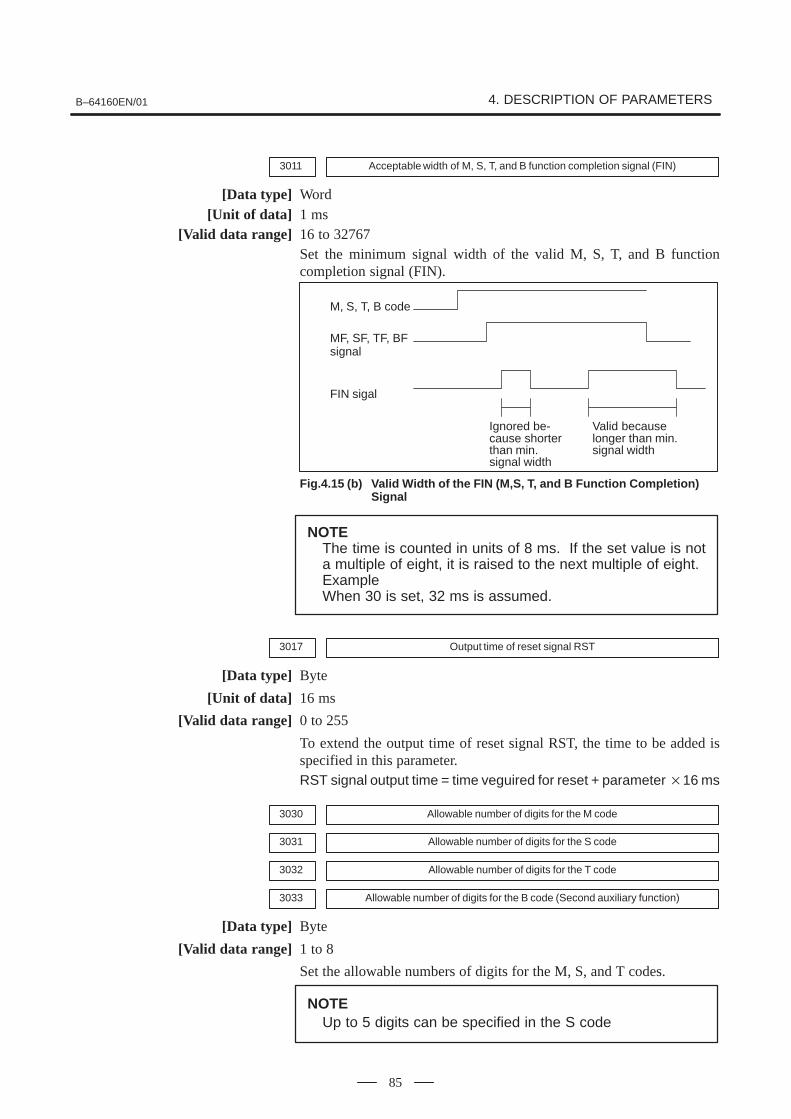
B–64160EN/01 4. DESCRIPTION OF PARAMETERS
85
3011 Acceptable width of M, S, T, and B function completion signal (FIN)
[Data type] Word[Unit of data] 1 ms
[Valid data range] 16 to 32767Set the minimum signal width of the valid M, S, T, and B functioncompletion signal (FIN).
M, S, T, B code
MF, SF, TF, BFsignal
FIN sigal
Ignored be-cause shorterthan min.signal width
Valid becauselonger than min.signal width
Fig.4.15 (b) Valid Width of the FIN (M,S, T, and B Function Completion) Signal
NOTEThe time is counted in units of 8 ms. If the set value is nota multiple of eight, it is raised to the next multiple of eight.ExampleWhen 30 is set, 32 ms is assumed.
3017 Output time of reset signal RST
[Data type] Byte
[Unit of data] 16 ms
[Valid data range] 0 to 255
To extend the output time of reset signal RST, the time to be added isspecified in this parameter.RST signal output time = time veguired for reset + parameter �16 ms
3030 Allowable number of digits for the M code
3031 Allowable number of digits for the S code
3032 Allowable number of digits for the T code
3033 Allowable number of digits for the B code (Second auxiliary function)
[Data type] Byte
[Valid data range] 1 to 8
Set the allowable numbers of digits for the M, S, and T codes.
NOTEUp to 5 digits can be specified in the S code

4. DESCRIPTION OF PARAMETERS B–64160EN/01
86
#7COR
#6 #5 #4 #3FKY
#2SKY
#1CEM
#03100
[Data type] Bit
CEM On screens such as the operation history screen and help screen, keys onthe MDI panel are indicated:0 : In English.1 : With graphics qualifying for CE marking. (A character generator
supporting graphics qualifying for CE marking is required.)
SKY MDI key board use:0 : Standard keys.1 : Small keys.
NOTESet this parameter when using the 10.4” LCD (with ten softkeys). After this parameter has been set, the power must beturned off then back on for the setting to become effective.
FKY MDI keyboard0 : Small type keys are used.1 : Standard keys are used.
NOTESet this parameter when using the 7.2”/8.4” LCD (with sevensoft keys). After this parameter has been set, the power mustbe turned off then back on for the setting to becomeeffective.
COR Display0 : Monochrome display1 : Color display
NOTEWhen using the 8.4” LCD, set this bit to 1.
#73101
#6 #5 #4BGD
#3 #2 #1KBF
#0
[Data type] Bit
KBF When the screen or mode is changed, the contents of the key–in buffer are:0 : Cleared.1 : Not cleared.
4.16PARAMETERS OF DISPLAY AND EDIT

B–64160EN/01 4. DESCRIPTION OF PARAMETERS
87
NOTEWhen KBF = 1, the contents of the key–in buffer can all be
cleared at one time by pressing the key followed by the
key.CAN
SHIFT
BGD In background editing, a program currently selected in the foreground:0 : Cannot be selected. (BP/S alarm No.140 is issued disabling
selection.)1 : Can be selected. (However, the program cannot be edited, only
displayed.)
3102 SPN ITA FRN GRM JPN#7 #6 #5 #4 #3 #2 #1 #0
#73119
#6 #5 #4 #3 #2 #1POR
#0
#73190
#6CHI2
#5 #4 #3 #2 #1 #0
NOTEWhen this parameter has been set, the power must beturned off before operation is continued.
[Data type] Bit
Select the language to be used for the display.
POR SPN ITA CHI2 FRN GRM JPN Language0 0 0 0 0 0 0 English
0 0 0 0 0 0 1 Japanese
0 0 0 0 0 1 0 German
0 0 0 0 1 0 0 French
0 0 0 1 0 0 0 Chinese
0 0 1 0 0 0 0 Italian
0 1 0 0 0 0 0 Spanish
1 0 0 0 0 0 0 Portuguese
3103#7 #6 #5 #4 #3 #2
NMH#1 #0
[Data type] Bit
NMH The system alarm history screen is:0 : Not displayed.1 : Displayed.

4. DESCRIPTION OF PARAMETERS B–64160EN/01
88
#73104
#6 #5 #4 #3PPD
#2 #1 #0MCN
[Data type] Bit
MCN Machine position0 : Not displayed according to the unit of input.
(Regardless of whether input is made in mm or inches, the machineposition is displayed in mm for millimeter machines, or in inches forinch machines.)
1 : Displayed according to the unit of input.(When input is made in mm, the machine position is displayed in mm,and when input is made in inches, the machine position is displayed ininches accordingly.)
PPD Relative position display when a coordinate system is set0 : Not preset1 : Preset
NOTEWhen PPD is set to 1 and the absolute position display is presetby one of the following, the relative position display is also presetto the same value as the absolute position display:1) The manual reference position return2) Setting of a coordinate system by G92
#7
3105
#6 #5 #4 #3 #2DPS
#1PCF
#0DPF
[Data type] Bit
DPF Display of the actual speed on the current position display screen,program check screen and program screen (MD1 mode)0 : Not displayed1 : Displayed
PCF Addition of the movement of the PMC–controlled axes to the actual speeddisplay0 : Added1 : Not added
NOTEFor each setting, movement along any axis other than thosecontrolled by the CNC (see the description of parameter No.1010) is not reflected in the actual speed display.
DPS Actual spindle speed and T code0 : Not always displayed1 : Always displayed

B–64160EN/01 4. DESCRIPTION OF PARAMETERS
89
#7OHS3106
#6 #5 #4OPH
#3 #2 #1GPL
#0
[Data type] Bit
GPL On the program list screen, the list–by–group function is:0 : Disabled1 : Enabled
OPH The operation history screen is:0 : Not displayed.1 : Displayed.
OHS Operation history sampling is:0 : Performed.1 : Not performed.
#7MDL3107
#6 #5 #4SOR
#3 #2DNC
#1 #0
[Data type] Bit
DNC Upon reset, the program display for DNC operation is:0 : Not cleared1 : Cleared
SOR Display of the program directory0 : Programs are listed in the order of registration.1 : Programs are listed in the order of program number.
MDL Display of the modal state on the program display screen0 : Not displayed1 : Displayed (only in the MDI mode)
#7JSP3108
#6 #5 #4WCI
#3PCT
#2 #1 #0
[Data type] Bit
PCT On the 7–pieces type soft key display program check screen and12–pieces type soft key display position screen, T code displayed0 : is a T code specified in a program (T).1 : is a T code specified by the PMC (HD. T/NX. T)
WCI On the workpiece coordinate system screen, a counter input is:0 : Disabled.1 : Enabled.
JSP On the current position display screen and program check screen, jog feed is:0 : Not displayed.1 : Displayed.
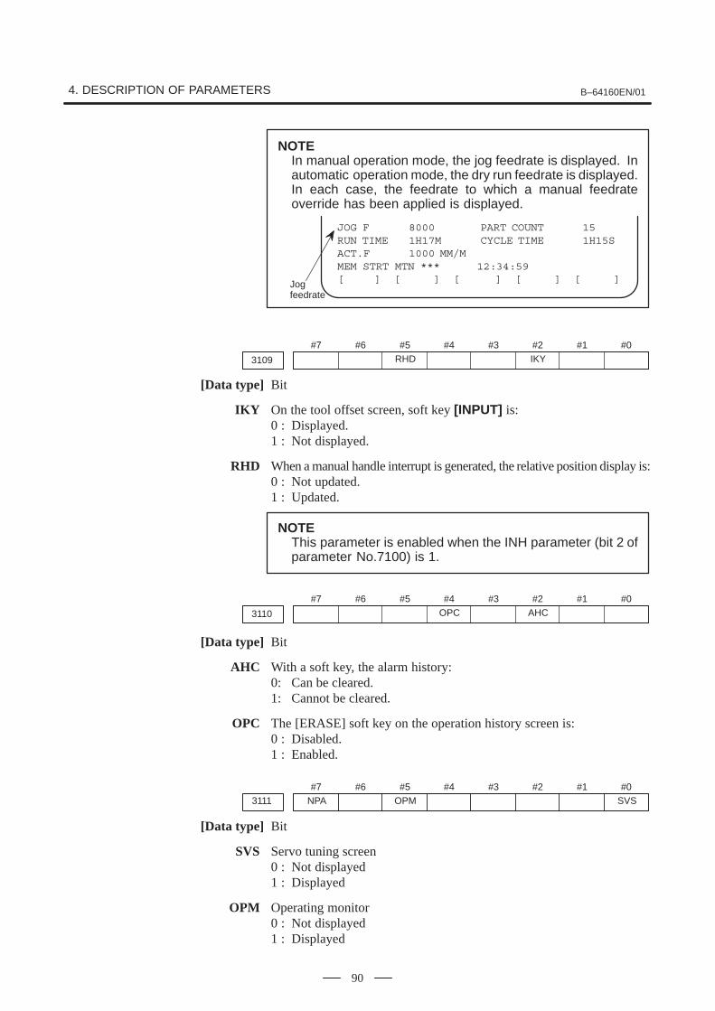
4. DESCRIPTION OF PARAMETERS B–64160EN/01
90
NOTEIn manual operation mode, the jog feedrate is displayed. Inautomatic operation mode, the dry run feedrate is displayed.In each case, the feedrate to which a manual feedrateoverride has been applied is displayed.
JOG F 8000 PART COUNT 15RUN TIME 1H17M CYCLE TIME 1H15SACT.F 1000 MM/MMEM STRT MTN *** 12:34:59[ ] [ ] [ ] [ ] [ ]Jog
feedrate
#7
3109
#6 #5RHD
#4 #3 #2IKY
#1 #0
[Data type] Bit
IKY On the tool offset screen, soft key [INPUT] is:0 : Displayed.1 : Not displayed.
RHD When a manual handle interrupt is generated, the relative position display is:0 : Not updated.1 : Updated.
NOTEThis parameter is enabled when the INH parameter (bit 2 ofparameter No.7100) is 1.
#7
3110
#6 #5 #4OPC
#3 #2AHC
#1 #0
[Data type] Bit
AHC With a soft key, the alarm history:0: Can be cleared.1: Cannot be cleared.
OPC The [ERASE] soft key on the operation history screen is:0 : Disabled.1 : Enabled.
#7NPA3111
#6 #5OPM
#4 #3 #2 #1 #0SVS
[Data type] Bit
SVS Servo tuning screen0 : Not displayed1 : Displayed
OPM Operating monitor0 : Not displayed1 : Displayed

B–64160EN/01 4. DESCRIPTION OF PARAMETERS
91
NPA Action taken when an alarm is generated or when an operator message isentered0 : The display shifts to the alarm or message screen.1 : The display does not shift to the alarm or message screen.
#73112
#6 #5OPH
#4 #3EAH
#2OMH
#1 #0SGD
NOTEWhen this parameter is set, the power must be turned offbefore operation is continued.
[Data type] Bit
SGD Servo waveform0 : Not displayed1 : Displayed
NOTEIf SGD is set to 1, no graphic display other than servowaveform display is done.
OMH The external operator message history screen is:0 : Not displayed.1 : Displayed.
EAH Messages of the exfernal alam/macro alarm in alarm history:0 : Not recorded1 : Recorded
OPH The operation history log function is:0 : Enabled.1 : Disabled.
#7MS13113
#6MS0
#5DCL
#4 #3 #2 #1 #0MHC
[Data type] Bit
MHC External operator message history data:0 : Cannot be cleared.1 : Can be cleared.
(Such data can be cleared using the [CLEAR] soft key.)
DCL The compensation function for the touch panel on the display is:0 : Disabled.1 : Enabled.
MS0, MS1 A combination of the number of characters preserved as external operatormessage history data and the number of history data items is set accordingto the table below.
MS1 MS0 Number of historydata characters
Number of historydata items
0 0 255 8
0 1 200 10
1 0 100 18
1 1 50 32

4. DESCRIPTION OF PARAMETERS B–64160EN/01
92
NOTEWhen the values of MS0 and MS1 are changed, all preservedexternal operator message history data is cleared.
#73114
#6ICS
#5IUS
#4IMS
#3ISY
#2IOF
#1IPR
#0IPO
[Data type] Bit
IPO When the POS function key is pressed while the position display screen is
being displayed:0 : The screen is changed.1 : The screen is not changed.
IPR When the PROG function key is pressed while the program screen is being
displayed:0 : The screen is changed.1 : The screen is not changed.
IOF When the OFFSETSETTING function key is pressed while the offset/setting screen is
being displayed:0 : The screen is changed.1 : The screen is not changed.
ISY When the SYSTEM function key is pressed while the system screen is being
displayed:0 : The screen is changed.1 : The screen is not changed.
IMS When the MESSAGE function key is pressed while the message screen is being
displayed:0 : The screen is changed.1 : The screen is not changed.
IUS When the CUSTOMGRAPH (using the small MDI) or GRAPH (using the standard MDI)
function key is pressed while the custom or graphic screen is beingdisplayed:0 : The screen is changed.1 : The screen is not changed.
ICS When the CUSTOM (using the standard MDI) function key is pressed while
the custom screen is being displayed:0 : The screen is changed.1 : The screen is not changed.
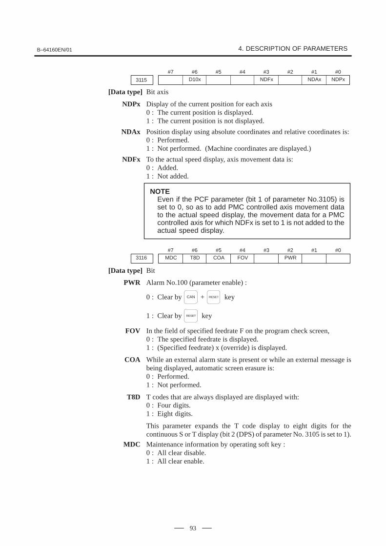
B–64160EN/01 4. DESCRIPTION OF PARAMETERS
93
#7
3115
#6D10x
#5 #4 #3NDFx
#2 #1NDAx
#0NDPx
[Data type] Bit axis
NDPx Display of the current position for each axis0 : The current position is displayed.1 : The current position is not displayed.
NDAx Position display using absolute coordinates and relative coordinates is:0 : Performed.1 : Not performed. (Machine coordinates are displayed.)
NDFx To the actual speed display, axis movement data is:0 : Added.1 : Not added.
NOTEEven if the PCF parameter (bit 1 of parameter No.3105) isset to 0, so as to add PMC controlled axis movement datato the actual speed display, the movement data for a PMCcontrolled axis for which NDFx is set to 1 is not added to theactual speed display.
#7MDC3116
#6T8D
#5COA
#4FOV
#3 #2PWR
#1 #0
[Data type] Bit
PWR Alarm No.100 (parameter enable) :
0 : Clear by CAN + RESET key
1 : Clear by RESET key
FOV In the field of specified feedrate F on the program check screen,0 : The specified feedrate is displayed.1 : (Specified feedrate) x (override) is displayed.
COA While an external alarm state is present or while an external message isbeing displayed, automatic screen erasure is:0 : Performed.1 : Not performed.
T8D T codes that are always displayed are displayed with:0 : Four digits.1 : Eight digits.
This parameter expands the T code display to eight digits for thecontinuous S or T display (bit 2 (DPS) of parameter No. 3105 is set to 1).
MDC Maintenance information by operating soft key :0 : All clear disable.1 : All clear enable.
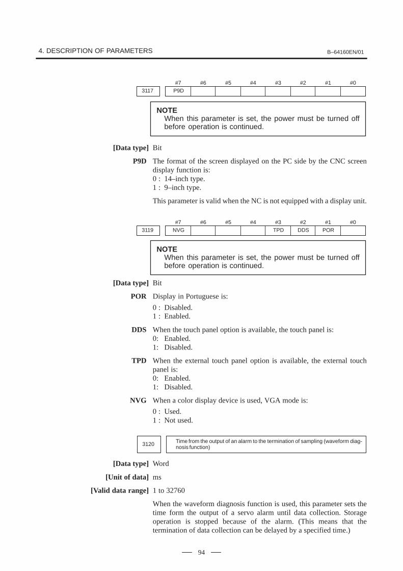
4. DESCRIPTION OF PARAMETERS B–64160EN/01
94
#7P9D3117
#6 #5 #4 #3 #2 #1 #0
NOTEWhen this parameter is set, the power must be turned offbefore operation is continued.
[Data type] Bit
P9D The format of the screen displayed on the PC side by the CNC screendisplay function is:0 : 14–inch type.1 : 9–inch type.
This parameter is valid when the NC is not equipped with a display unit.
#7NVG3119
#6 #5 #4 #3TPD
#2DDS
#1POR
#0
NOTEWhen this parameter is set, the power must be turned offbefore operation is continued.
[Data type] Bit
POR Display in Portuguese is:
0 : Disabled.1 : Enabled.
DDS When the touch panel option is available, the touch panel is:0: Enabled.1: Disabled.
TPD When the external touch panel option is available, the external touchpanel is:0: Enabled.1: Disabled.
NVG When a color display device is used, VGA mode is:
0 : Used.1 : Not used.
3120 Time from the output of an alarm to the termination of sampling (waveform diag-nosis function)
[Data type] Word
[Unit of data] ms
[Valid data range] 1 to 32760
When the waveform diagnosis function is used, this parameter sets thetime form the output of a servo alarm until data collection. Storageoperation is stopped because of the alarm. (This means that thetermination of data collection can be delayed by a specified time.)

B–64160EN/01 4. DESCRIPTION OF PARAMETERS
95
3122 Time interval used to record time data in operation history
[Data type] Word
[Unit of data] min
[Valid data range] 0 to 1439
Time data is recorded in operation history at set intervals. When 0 isspecified in this parameter, 10 minutes is assumed as the default.However, note that time data is not recorded if there is no data to berecorded at the specified time.
3123 Time until screen clear function is applied
[Data type] Byte
[Unit of data] min
[Valid data range] 1 to 255
This parameter specifies the period that must elapse before the screenclear function is applied. If 0 is set, the screen is not cleared.
Moreover, this parameter is valid only when it is set on the path 1 side.
#7D083124
#6D07
#5D06
#4D05
#3D04
#2D03
#1D02
#0D01
D163125 D15 D14 D13 D12 D11 D10 D09
D243126 D23 D22 D21 D20 D19 D18 D17
3127 D25
[Data type] Bit
Dxx (xx: 01 to 25) When modal G code is displayed on the program check screen, the xxgroup G code is:0 : Displayed.1 : Not displayed.
NOTESet these parameters when using the display with seven softkeys.
3134 Axis display order on workpiece coordinate system screen and workpiece shift screen
[Data type] Byte axis
[Valid data range] 0, 1 to the number of controlled axes
This parameter specifies the order in which axes are displayed on theworkpiece coordinate system screen.When the parameters of all axes are set to 0, all axes are displayed.When the parameters of some axes are set, the axes for which a value of 0is specified do not appear. The displayed axes are consecutive withoutspaces being left for non–displayed axes.

4. DESCRIPTION OF PARAMETERS B–64160EN/01
96
3151 Number of the axis for which the first load meter for the servo motor is used
3152 Number of the axis for which the second load meter for the servo motor is used
3153 Number of the axis for which the third load meter for the servo motor is used
3154 Number of the axis for which the fourth load meter for servo motor is used
[Data type] Byte
[Valid data range] 0, 1, . . . , the number of control axes
Set the numbers of the axes for which measurement values on the loadmeters for the fourth servo motors are displayed. Set the parameters to 0for those axes for which a load meter need not be displayed.
3191 STS WKI#7 #6 #5 #4 #3 #2 #1 #0
[Data type] Bit
WKI On the workpiece coordinate system setting screen, the soft key [INPUT]is:0 : Displayed.1 : Not displayed.
STS When data is input on the setting screen, a confirmation message is:0 : Not displayed.1 : Displayed.
TRA T2P#7 #6 #5 #4 #3 #2 #1 #0
3192
[Data type] Bit
T2P If two points are pressed on the touch panel, it is assumed that:0 : A mid point is pressed.1 : The first point is pressed.
NOTE1 If two or more points are pressed during a sampling period,
it is assumed that a mid point is pressed.2 In open CNC, the parameter is valid just for CNC screen
display function.
TRA If a point on the touch panel is kept pressed for a time specified inparameter No. 3197 or longer,0 : P/S alarm 5303 is not raised.1 : P/S alarm 5303 is raised.
NOTEIn open CNC, the parameter is valid just for the CNC screendisplay function.

B–64160EN/01 4. DESCRIPTION OF PARAMETERS
97
3197 Detection time of continuous pressing on touch panel
[Data type] Byte
[Unit of data] s
[Valid data range] 0 to 255
This parameter is valid if bit 2 (TRA) of parameter No. 3192 is set to 1.
Set a period of continuous pressing on the touch panel which causesP/S5305 alarm to be raised. If 0 is set, a period of 20 s is assumed.
#7MIP3201
#6NPE
#5N99
#4 #3PUO
#2REP
#1RAL
#0RDL
[Data type] Bit
RDL When a program is registered by input/output device external control0 : The new program is registered following the programs already
registered.1 : All registered programs are deleted, then the new program is
registered.Note that programs which are protected from being edited are notdeleted.
RAL When programs are registered through the reader/puncher interface0 : All programs are registered.1 : Only one program is registered.
REP Action in response to an attempt to register a program whose number isthe same as that of an existing program0 : An alarm is generated.1 : The existing program is deleted, then the new program is registered.
Note that if the existing program is protected from being edited, it isnot deleted, and an alarm is generated.
PUO When address O of a program number is output in ISO code:0 : “:” is output.1 : “O” is output.
N99 With an M99 block, when bit 6 (NPE) of parameter No.3201 = 0, programregistration is assumed to be:0 : Completed1 : Not completed
NPE With an M02, M30, or M99 block, program registration is assumed to be:0 : Completed1 : Not completed
MIP Program registration by external start signal (MINP) :0 : Not performed.1 : Performed.
#73202
#6PSR
#5CPD
#4NE9
#3OSR
#2CND
#1OLV
#0NE8
[Data type] Bit
NE8 Editing of subprograms with program numbers 8000 to 89990 : Not inhibited1 : Inhibited
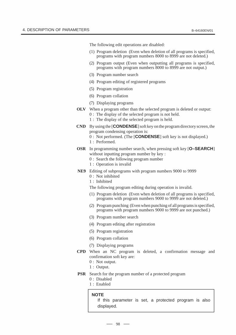
4. DESCRIPTION OF PARAMETERS B–64160EN/01
98
The following edit operations are disabled:
(1) Program deletion (Even when deletion of all programs is specified,programs with program numbers 8000 to 8999 are not deleted.)
(2) Program output (Even when outputting all programs is specified,programs with program numbers 8000 to 8999 are not output.)
(3) Program number search
(4) Program editing of registered programs
(5) Program registration
(6) Program collation
(7) Displaying programs
OLV When a program other than the selected program is deleted or output:0 : The display of the selected program is not held.1 : The display of the selected program is held.
CND By using the [CONDENSE] soft key on the program directory screen, theprogram condensing operation is:0 : Not performed. (The [CONDENSE] soft key is not displayed.)1 : Performed.
OSR In programming number search, when pressing soft key [O–SEARCH]without inputting program number by key :0 : Search the following program number1 : Operation is invalid
NE9 Editing of subprograms with program numbers 9000 to 99990 : Not inhibited1 : InhibitedThe following program editing during operation is invalid.
(1) Program deletion (Even when deletion of all programs is specified,programs with program numbers 9000 to 9999 are not deleted.)
(2) Program punching (Even when punching of all programs is specified,programs with program numbers 9000 to 9999 are not punched.)
(3) Program number search
(4) Program editing after registration
(5) Program registration
(6) Program collation
(7) Displaying programs
CPD When an NC program is deleted, a confirmation message andconfirmation soft key are:0 : Not output.1 : Output.
PSR Search for the program number of a protected program0 : Disabled1 : Enabled
NOTEIf this parameter is set, a protected program is alsodisplayed.

B–64160EN/01 4. DESCRIPTION OF PARAMETERS
99
#7MCL3203
#6MER
#5MIE
#4 #3 #2 #1 #0
[Data type] Bit
MIE After MDI operation is started, program editing during operation is:0 : Enabled1 : Disabled
MER When the last block of a program has been executed at single blockoperation in the MDI mode, the executed block is:0 : Not deleted1 : Deleted
NOTEWhen MER is set to 0, the program is deleted if theend–of–record mark (%) is read and executed. (The mark %is automatically inserted at the end of a program.)
MCL Whether a program prepared in the MDI mode is cleared by reset0 : Not deleted1 : deleted
#73204
#6MKP
#5 #4 #3 #2EXK
#1 #0PAR
[Data type] Bit
PAR When a small keyboard is used, characters “[” and “]” are:0 : Used as “[” and “]”.1 : Used as “(” and “)”.
EXK The input character extension function is:0 : Not used. ([C–EXT] soft key is displayed.)1 : Used.
NOTEThe [C–EXT] soft key is used to select an operation on theprogram screen. This soft key enables the entry of “(”, “)”,and “@” using soft keys. This soft key is useful when usingthe small MDI keyboard, which does not have the “(”, “)”, and“@” keys.
MKP When M02, M30, or EOR(%) is executed during MDI operation, thecreated MDI program is:0 : Erased automatically.1 : Not erased automatically.
NOTEIf the MER parameter (bit 6 of parameter No.3203) is 1,executing the last block provides a choice of whether toautomatically erase a created program.
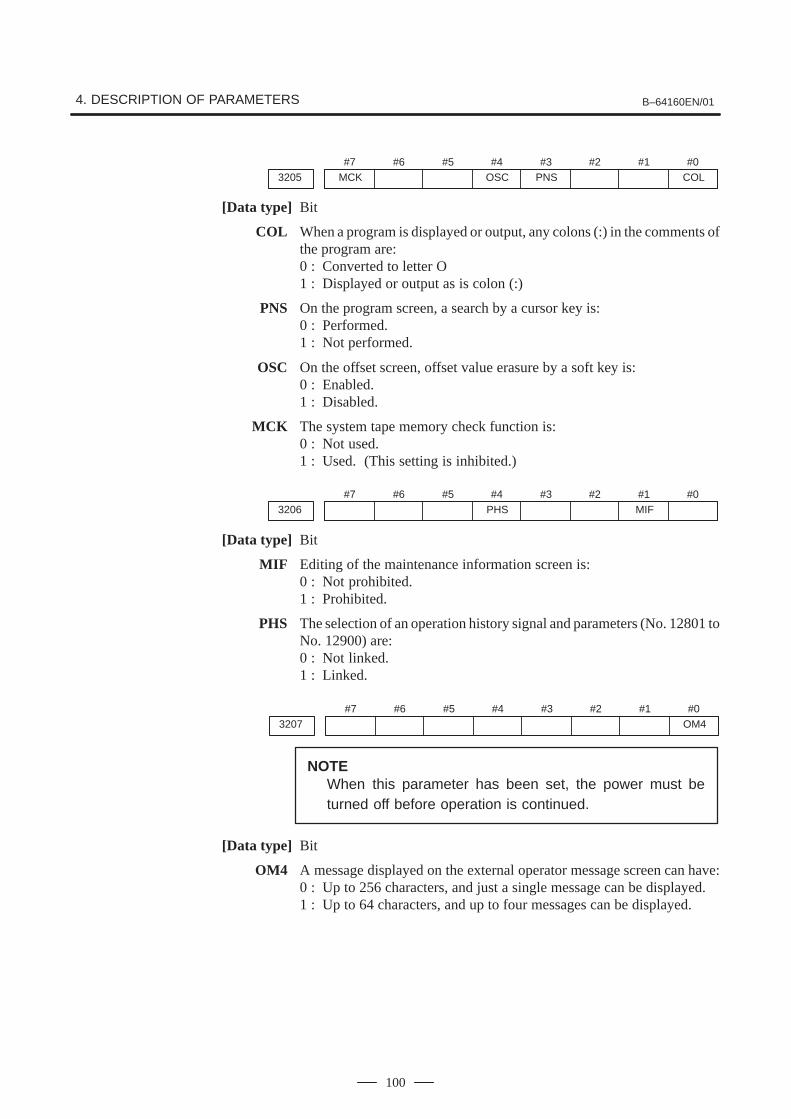
4. DESCRIPTION OF PARAMETERS B–64160EN/01
100
#7MCK3205
#6 #5 #4OSC
#3PNS
#2 #1 #0COL
[Data type] Bit
COL When a program is displayed or output, any colons (:) in the comments ofthe program are:0 : Converted to letter O1 : Displayed or output as is colon (:)
PNS On the program screen, a search by a cursor key is:0 : Performed.1 : Not performed.
OSC On the offset screen, offset value erasure by a soft key is:0 : Enabled.1 : Disabled.
MCK The system tape memory check function is:0 : Not used.1 : Used. (This setting is inhibited.)
#73206
#6 #5 #4PHS
#3 #2 #1MIF
#0
[Data type] Bit
MIF Editing of the maintenance information screen is:0 : Not prohibited.1 : Prohibited.
PHS The selection of an operation history signal and parameters (No. 12801 toNo. 12900) are:0 : Not linked.1 : Linked.
#73207
#6 #5 #4 #3 #2 #1 #0OM4
NOTEWhen this parameter has been set, the power must beturned off before operation is continued.
[Data type] Bit
OM4 A message displayed on the external operator message screen can have:0 : Up to 256 characters, and just a single message can be displayed.1 : Up to 64 characters, and up to four messages can be displayed.

B–64160EN/01 4. DESCRIPTION OF PARAMETERS
101
#73208
#6 #5 #4 #3 #2 #1COK
#0SKY
[Data type] Bit
SKY The function key [SYSTEM] on the MDI panel is:0 : Enabled.1 : Disabled.
COK The automatic screen erase function is:0 : Enabled.1 : Disabled.
NOTEIf this parameter is set to 1, screen erasure by the CAN +FUNCTION key is enabled, irrespective of the setting ofparameter No. 3123.
#73209
#6 #5 #4 #3 #2 #1 #0MPD
[Data type] Bit
MPD When a subprogram is executed, the main program number is:0 : Not displayed.1 : Displayed.
3210 Password
[Data type] 2–word axis
This parameter sets a password for protecting program Nos. 9000 to 9999.When a value other than zero is set in this parameter and this value differsfrom the keyword set in parameter No.3211, bit 4 (NE9) of parameterNo.3202 for protecting program Nos. 9000 to 9999 is automatically set to1. This disables the editing of program Nos. 9000 to 9999. Until the valueset as the password is set as a keyword, NE9 cannot be set to 0 and thepassword cannot be modified.
NOTE1 The state where password � 0 and password � keyword is
referred to as the locked state. When an attempt is made tomodify the password by MDI input operation in this state, thewarning message “WRITE PROTECTED” is displayed toindicate that the password cannot be modified. When anattempt is made to modify the password with G10(programmable parameter input), P/S alarm No.231 is issued.
2 When the value of the password is not 0, the parameterscreen does not display the password. Care must be takenin setting a password.

4. DESCRIPTION OF PARAMETERS B–64160EN/01
102
3211 Keyword
[Data type] 2–word
When the value set as the password (set in parameter No.3210) is set inthis parameter, the locked state is released and the user can now modifythe password and the value set in bit 4 (NE9) of parameter No.3202.
NOTEThe value set in this parameter is not displayed. When thepower is turned off, this parameter is set to 0.
3216 Increment in sequence numbers inserted automatically
This parameter can be set at the “Setting screen”.
[Data type] Word
[Valid data range] 0 to 9999
Set the increment for sequence numbers for automatic sequence numberinsertion (when SEQ, #5 of parameter 0000, is set to 1.)
#7KEY3290
#6MCM
#5 #4IWZ
#3WZO
#2MCV
#1GOF
#0WOF
[Data type] Bit
WOF Setting the tool offset value by MDI key input is:0 : Not disabled1 : Disabled (With parameter No.3294 and No.3295, set the offset
number range in which updating the setting is to be disabled.)
GOF Setting the tool offset value by MDI key input is:0 : Not disabled1 : Disabled (With parameter No.3294 and No.3295, set the offset
number range in which updating the setting is to be disabled.)
MCV Macro variable setting by MDI key input is:0 : Not disabled1 : Disabled
WZO Setting a workpiece zero point offset value by MDI key input is:0 : Not disabled1 : Disabled
IWZ Setting a workpiece zero point offset value or workpiece shift value(T–series) by MDI key input in the automatic operation activation or haltstate is:0 : Not disabled1 : Disabled
MCM The setting of custom macros by MDI key operation is:0 : Enabled regardless of the mode.1 : Enabled only in the MDI mode.
KEY For memory protection keys:0 : The KEY1, KEY2, KEY3, and KEY4 signals are used.1 : Only the KEY1 signal is used.

B–64160EN/01 4. DESCRIPTION OF PARAMETERS
103
NOTEThe functions of the signals depend on whether KEY=0 orKEY=1.When KEY = 0:
– KEY1: Enables a tool offset value and a workpiece zero point offset value to be input.
– KEY2: Enables setting data and macro variables to be input.– KEY3: Enables program registration and editing.– KEY4: Enables PMC data (counter and data table) to be
input.
When KEY = 1:– KEY1: Enables program registration and editing, and
enables PMC parameter input.– KEY2 to KEY4: Not used
#73291
#6 #5 #4 #3 #2 #1 #0WPT
[Data type] Bit
WPT The input of the tool wear compensation amount is:0 : Enabled according to memory protection key signal KEY1.1 : Always enabled.
#7PK53292
#6 #5 #4 #3 #2 #1 #0
[Data type] Bit
PK5 The KEYPRM signal (memory protection signal, parameter writesetting) is:0 : Disabled.1 : Enabled.

4. DESCRIPTION OF PARAMETERS B–64160EN/01
104
3294 Start number of tool offset values whose input by MDI is disabled
3295 Number of tool offset values (from the start number) whose input by MDI is disabled
[Data type] Word
When the modification of tool offset values by MDI key input is to bedisabled using bit 0 (WOF) of parameter No.3290 and bit 1 (GOF) ofparameter No.3290, parameter Nos. 3294 and 3295 are used to set therange where such modification is disabled. In parameter No.3294, set theoffset number of the start of tool offset values whose modification isdisabled. In parameter No.3295, set the number of such values.When 0 or a negative value is set in parameter No.3294 or parameterNo.3295, no modification of the tool offset values is allowed.
When the value set with parameter No.3294 is greater than the maximumtool offset count, no modification is allowed.
[Example]
The following setting disables the modification of both the tool geometrycompensation values and tool wear compensation values correspondingto offset numbers 51 to 60:Bit 1 (GOF) of parameter No.3290=1 (Disables tool offset valuemodification.)
Bit 0 (WOF) of parameter No.3290=1 (Disables tool wear compensationvalue modification.)
Parameter No.3294 = 51Parameter No.3295 = 60If bit 0 (WOF) of parameter No.3290 is set to 0, the modification of thetool offset values alone is disabled. The tool wear compensation valuesmay be modified.

B–64160EN/01 4. DESCRIPTION OF PARAMETERS
105
#7
3401
#6GSB
#5ABS
#4MAB
#3 #2 #1 #0DPI
[Data type] Bit
DPI When a decimal point is omitted in an address that can include a decimalpoint0 : The least input increment is assumed.1 : The unit of mm, inches, or second is assumed. (Pocket calculator type
decimal point input)
MAB Switching between the absolute and incremental commands in MDIoperation0 : Performed by G90 or G911 : Depending on the setting of ABS, #5 of parameter No.3401
ABS Program command in MDI operation0 : Assumed as an incremental command1 : Assumed as an absolute command
NOTEABS is valid when MAB, #4 of parameter No.3401, is set to 1.
GSB The G code system is set.
GSB G code0 G code system A
1 G code system B
NOTEWhen this parameter is set, the power must be turned offbefore operation is continued.
#7
3402
#6CLR
#5 #4 #3G91
#2G19
#1G18
#0G01G23
[Data type] Bit
G01 Mode entered when the power is turned on or when the control is cleared0 : G00 mode (positioning)1 : G01 mode (linear interpolation)
G18 and G19 Plane selected when power is turned on or when the control is cleared
G19 G18 G17, G18 or G19 mode
0 0 G17 mode (plane XY)
0 1 G18 mode (plane ZX)
1 0 G19 mode (plane YZ)
G91 When the power is turned on or when the control is cleared0 : G90 mode (absolute command)1 : G91 mode (incremental command)
CLR Reset button on the MDI panel, external reset signal, reset and rewindsignal, and emergency stop signal0 : Cause reset state.1 : Cause clear state.
For the reset and clear states, refer to Appendix in the Operator’s Manual.
4.17PARAMETERS OF PROGRAMS

4. DESCRIPTION OF PARAMETERS B–64160EN/01
106
G23 When the power is turned on0 : G22 mode (stored stroke check on)1 : G23 mode (stored stroke check off)
#73403
#6AD2
#5CIR
#4 #3 #2 #1 #0
[Data type] Bit
CIR When neither the distance (I, J, K) from a start point to the center nor an arcradius (R) is specified in circular interpolation (G02, G03):0 : The tool moves to an end point by linear interpolation.1 : P/S alarm No.022 is issued.
AD2 Specification of the same address two or more times in a block is:0 : Enabled (Next specification is enabled.)1 : Disabled (P/S alarm No.5074)
NOTE1 When 1 is set, specifying two or more G codes of the same
group in a block will also result in an alarm being issued.2 Up to three M codes can be specified in a single block, when
bit 7 (M3B) of parameter No.3404 is set to 1.
#7
3404
#6EOR
#5M02
#4M30
#3 #2SBP
#1POL
#0NOPM3B
[Data type] Bit
NOP When a program is executed, a block consisting of an O number, EOB, orN number is:0 : Not ignored, but regarded as being one block.1 : Ignored.
POL For a command address allowing a decimal point, omission of the decimalpoint is:0 : Enabled1 : Disabled (P/S alarm No.5073)
SBP Address P of the block including M198 in the subprogram call function0 : Indicating a file number1 : Indicating a program number
M30 When M30 is specified in a memory operation:0 : M30 is sent to the machine, and the head of the program is
automatically searched for. So, when the ready signal FIN is returnedand a reset or reset and rewind operation is not performed, theprogram is executed, starting from the beginning.
1 : M30 is sent to the machine, but the head of the program is not searchedfor. (The head of the program is searched for by the reset and rewindsignal.)

B–64160EN/01 4. DESCRIPTION OF PARAMETERS
107
M02 When M02 is specified in memory operation0 : M02 is sent to the machine, and the head of the program is automati-
cally searched for. So, when the end signal FIN is returned and a resetor reset and rewind operation is not performed, the program isexecuted, starting from the beginning.
1 : M02 is sent to the machine, but the head of the program is not searchedfor. (The head of the program is searched for by the reset and rewindsignal.)
EOR When the end–of–record mark (%) is read during program execution:0 : P/S alarm No.5010 occurs. (Automatic operation is stopped, and the
system enters the alarm state.)1 : No alarm occurs. (Automatic operation is stopped, and the system is
reset.)
M3B The number of M codes that can be specified in one block0 : One1 : Up to three
#7
3406
#6 #5C05
#4C04
#3C03
#2C02
#1C01
#0C07
3407 C14 C13 C11 C10 C09 C08C15
3408 C19 C18 C17 C16
CFH3409
[Data type] Bit
Cxx (xx: 01 to 19) When bit 6 (CLR) of parameter No.3402 is 1, the reset button on the MDIpanel, the external reset signal, the reset and rewind signal, or emergencystop will,0 : Clear the G code with group number xx.1 : Not clear the G code with group number xx.
CFH When bit 6 (CLR) of parameter No.3402 is 1, the reset button on the MDIpanel, the external reset signal, the reset and rewind signal, or emergencystop will,0 : Clear F codes, H codes (for the M series), D codes (for the M series),
and T codes (for the T series).1 : Not clear F codes and D codes.
3410 Tolerance of arc radius
[Data type] 2–word
[Unit of data]Increment system IS–A IS–B Unit
Millimeter input 0.01 0.001 mm
Inch input 0.001 0.0001 inch
[Valid data range] 1 to 99999999
When a circular interpolation command (G02, G03) is executed, thetolerance for the radius between the start point and the end point is set. Ifthe difference of radii between the start point and the end point exceeds thetolerance set here, a P/S alarm No.20 is informed.

4. DESCRIPTION OF PARAMETERS B–64160EN/01
108
NOTEWhen the set value is 0, the difference of radii is not checked.
3411 M code preventing buffering 1
3412 M code preventing buffering 2
3413 M code preventing buffering 3
� �
3420 M code preventing buffering 10
[Data type] Byte
[Valid data range] 0 to 255
Set M codes that prevent buffering the following blocks. If processingdirected by an M code must be performed by the machine withoutbuffering the following block, specify the M code.
M00, M01, M02, and M30 always prevent buffering even when they arenot specified in these parameters.
3421 Minimum value 1 of M code preventing buffering
3422 Maximum value 1 of M code preventing buffering
3423 Minimum value 2 of M code preventing buffering
3424 Maximum value 2 of M code preventing buffering
3425 Minimum value 3 of M code preventing buffering
3426 Maximum value 3 of M code preventing buffering
3427 Minimum value 4 of M code preventing buffering
3428 Maximum value 4 of M code preventing buffering
3429 Minimum value 5 of M code preventing buffering
3430 Maximum value 5 of M code preventing buffering
3431 Minimum value 6 of M code preventing buffering
3432 Maximum value 6 of M code preventing buffering
[Data type] Word
[Valid data range] 0 to 65535
When a specified M code is within the range specified with parameterNos. 3421 and 3422, 3423 and 3424, 3425 and 3426, 3427 and 3428, 3429and 3430, or 3431 and 3432, buffering for the next block is not performeduntil the execution of the block is completed.
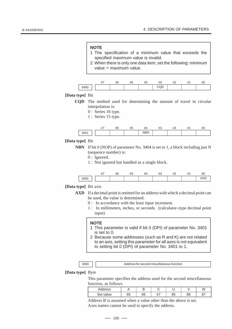
B–64160EN/01 4. DESCRIPTION OF PARAMETERS
109
NOTE1 The specification of a minimum value that exceeds the
specified maximum value is invalid.2 When there is only one data item, set the following: minimum
value = maximum value.
#7
3450
#6 #5 #4 #3CQD
#2 #1 #0
[Data type] Bit
CQD The method used for determining the amount of travel in circularinterpolation is:0 : Series 16 type.1 : Series 15 type.
#7
3451
#6 #5 #4NBN
#3 #2 #1 #0
[Data type] Bit
NBN If bit 0 (NOP) of parameter No. 3404 is set to 1, a block including just N(sequence number) is:0 : Ignored.1 : Not ignored but handled as a single block.
#7
3455
#6 #5 #4 #3 #2 #1 #0AXD
[Data type] Bit axis
AXD If a decimal point is omitted for an address with which a decimal point canbe used, the value is determined:0 : In accordance with the least input increment.1 : In millimeters, inches, or seconds. (calculator–type decimal point
input)
NOTE1 This parameter is valid if bit 0 (DPI) of parameter No. 3401
is set to 0.2 Because some addresses (such as R and K) are not related
to an axis, setting this parameter for all axes is not equivalentto setting bit 0 (DPI) of parameter No. 3401 to 1.
3460 Address for second miscellaneous function
[Data type] Byte
This parameter specifies the address used for the second miscellaneousfunction, as follows:
Address A B C U V W
Set value 65 66 67 85 86 87
Address B is assumed when a value other than the above is set.Axes names cannot be used to specify the address.

4. DESCRIPTION OF PARAMETERS B–64160EN/01
110
#73605
#6 #5 #4 #3 #2 #1 #0BDP
NOTEWhen this parameter has been set, the power must beturned off before operation is continued.
[Data type] Bit
BDP Both–direction pitch error compensation is:0 : Not used.1 : Used.
3620 Number of the pitch error compensation position for the reference position foreach axis
NOTEWhen this parameter is set, the power must be turned offbefore operation is continued.
[Data type] Word axis
[Unit of data] Number
[Valid data range] 0 to 1023
Set the number of the pitch error compensation position for the referenceposition for each axis.
3
2
1
–1
–2
Pitch error compensation value (absolute value)
Reference positionPitch error compensationposition (number)
Compensation position number
Set compensating value
31 32 33 34 35 36 37
+3 –1 –1 +1 +2 –1 –3
Fig.4.18 Pitch Error Compensation Position Number and Value (Example)
In the above example, set 33 as the number of the pitch errorcompensation position for the reference position.
4.18PARAMETERS OF PITCH ERROR COMPENSATION
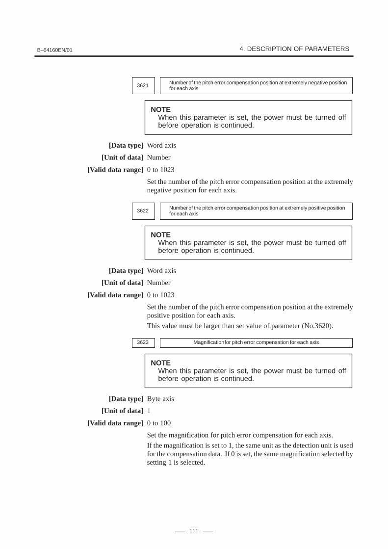
B–64160EN/01 4. DESCRIPTION OF PARAMETERS
111
3621 Number of the pitch error compensation position at extremely negative positionfor each axis
NOTEWhen this parameter is set, the power must be turned offbefore operation is continued.
[Data type] Word axis
[Unit of data] Number
[Valid data range] 0 to 1023
Set the number of the pitch error compensation position at the extremelynegative position for each axis.
3622 Number of the pitch error compensation position at extremely positive positionfor each axis
NOTEWhen this parameter is set, the power must be turned offbefore operation is continued.
[Data type] Word axis
[Unit of data] Number
[Valid data range] 0 to 1023
Set the number of the pitch error compensation position at the extremelypositive position for each axis.
This value must be larger than set value of parameter (No.3620).
3623 Magnification for pitch error compensation for each axis
NOTEWhen this parameter is set, the power must be turned offbefore operation is continued.
[Data type] Byte axis
[Unit of data] 1
[Valid data range] 0 to 100
Set the magnification for pitch error compensation for each axis.
If the magnification is set to 1, the same unit as the detection unit is usedfor the compensation data. If 0 is set, the same magnification selected bysetting 1 is selected.

4. DESCRIPTION OF PARAMETERS B–64160EN/01
112
3624 Interval between pitch error compensation positions for each axis
NOTEWhen this parameter is set, the power must be turned offbefore operation is continued.
[Data type] 2–word axis
[Unit of data]Increment system IS–A IS–B Unit
Millimeter machine 0.01 0.001 mm
Inch machine 0.001 0.0001 inch
Rotation axis 0.01 0.001 deg
[Valid data range] 0 to 99999999
The pitch error compensation positions are arranged with equal spacing.The space between two adjacent positions is set for each axis. Theminimum interval between pitch error compensation positions is limitedand obtained from the following equation:
Minimum interval between pitch error compensation positions =maximum feedrate (rapid traverse rate)/7500
Units: Minimum interval between pitch error compensationpositions: mm, inch, degMaximum feedrate: mm/min, inch/min, deg/min
Example: When the maximum feedrate is 15000 mm/min, the minimuminterval between pitch error compensation positions is 2 mm.
If setting a magnification causes the absolute value of the compensationamount at a compensation position to exceed 100, enlarge the intervalbetween the compensation positions by using a multiple calculated asfollows:
Multiple = maximum compensation amount (absolute value)/128 (Round the remainder up to the nearest integer.)
Minimum interval between pitch error compensation positions = Value obtained from the above maximum feedrate x multiple
Example 1) For linear axis� Machine stroke: –400 mm to + 800 mm
� Interval between the pitch error compensation positions: 50 mm
� No.of the compensation position of the reference position: 40
If the above is specified, the No.of the farthest compensation point in thenegative direction is as follows:
No.of the compensation position of the reference position – (Machinestroke length in the negative direction/Interval between thecompensation points) + 1= 40 – 400/50 + 1=33

B–64160EN/01 4. DESCRIPTION OF PARAMETERS
113
No.of the farthest compensation position in the positive direction is asfollows:
No.of the compensation position of the reference position + (Machinestroke length in the positive direction/Interval between thecompensation positions)= 40 + 800/50= 56
The correspondence between the machine coordinate and thecompensation position No.is as follows:
Machine coordinate (mm)
Compensationpoint No.
–400 –350 –100 –50 0 50 100 750 800
33 39 40 41 42 56
Compensation values are output at the positions indicated by �.
Therefore, set the parameters as follows:
Parameter Setting
No. 3620: Compensation point number for reference position 40
No. 3621: Compensation point number for farthest point in the negative direction 33
No. 3622: Compensation point number for farthest point in the positive direction 56
No. 3623: Compensation magnification 1
No. 3624: Compensation point interval 50000
The compensation value is output at the compensationn positionNo.corresponding to each section between the coordinates.
The following is an example of the compensation values.
No. 33 34 35 36 37 38 39 40 41 42 43 44 45 46 47 48 49
Compensationvalues +2 +1 +1 –2 0 –1 0 –1 +2 +1 0 –1 –1 –2 0 +1 +2
Pitch error compensation amount (absolute value)
Reference position
–400 –300 –200 –100 0 100 200 300 400 (mm)–1
–2
–3
–4
+4
+3
+2
+1

4. DESCRIPTION OF PARAMETERS B–64160EN/01
114
Example 2) For the rotation axis� Amount of movement per rotation: 360°� Interval between pitch error compensation position: 45°� No.of the compensation position of the reference position: 60
If the above is specified, the No.of the farthest compensation position inthe negative direction for the rotation axis is always equal to thecompensation position No.of the reference position.
The No.of the farthest compensation position in the positive direction isas follows:
No.of the compensation position of the reference position + (Moveamount per rotation/Interval between the compensation position)= 60 + 360/45= 68
The correspondence between the machine coordinate and thecompensation position No.is as follows:
The compensation value is output at the circled position.
If the sum of the compensation value from 61 to 68 is not zero, the pitcherror per rotation accumulates, resulting in a positional shift.
For compensation position 60, set the same compensation value as for 68.
Reference position 0.0
315.0
270.0
225.0
180.0
135.0
90.0
45.0(68)
(60)
(67)
(66)
(65)(64)
(63)
(62)
(61)
(+)
Set the parameters as follows:
Parameter Setting
No. 3620: Compensation point number for reference position 60
No. 3621: Compensation point number for farthest point in the negative direction 60
No. 3622: Compensation point number for farthest point in the positive direction 68
No. 3623: Compensation magnification 1
No. 3624: Compensation point interval 45000
The following is an example of compensation values.
No.of the compensation position
60 61 62 63 64 65 66 67 68
Compensation value +1 –2 +1 +3 –1 –1 –3 +2 +1

B–64160EN/01 4. DESCRIPTION OF PARAMETERS
115
Pitch error compensation value(absolute value)
Reference position
090 (deg)
–1
–2
–3
–4
+4
+3
+2
+1
0135 180 225 270 315 45 90 135 180 225 270 315 45
Machine coordinate
3625 Travel distance per revolution in pitch error compensation of rotation axis type
NOTEWhen this parameter has been set, the power must beturned off before operation is continued.
[Data type] 2–word axis
[Valid data range] 0 to 99999999
If the pitch error compensation of rotation axis type is performed (bit 1(ROSx) of parameter No. 1006 is set to 0 and bit 0 (ROTx) of parameterNo. 1006 is set to 1), set the travel distance per revolution. The traveldistance per revolution does not have to be 360 degrees, and a cycle ofpitch error compensation of rotation axis type can be set.
However, the travel distance per revolution, compensation interval, andnumber of compensation points must satisfy the following condition:
(Travel distance per revolution) = (Compensation interval) x(Number of compensation points)
The compensation at each compensation point must be set so that the totalcompensation per revolution equals 0.
NOTEIf 0 is set, the travel distance per revolution becomes 360degrees.

4. DESCRIPTION OF PARAMETERS B–64160EN/01
116
3626Number of pitch error compensation point at the farthest end in the negativedirection (for movement in the negative direction)
NOTEWhen this parameter has been set, the power must beturned off before operation is continued.
[Data type] Word axis
[Unit of data] Number
[Valid data range] 0 to 1023, 3000 to 4023
When using both–direction pitch error compensation, set the number ofpitch error compensation point at the farthest end in the negative directionfor a movement in the negative direction.
NOTE1 For a movement in the positive direction, set the
compensation point number at the farthest end in thenegative direction in parameter No. 3621.
2 A set of compensation data items for a single axis should notbe set to lie astride 1023 and 3000.
3627Pitch error compensation (absolute value) at reference position when a move-ment to the reference position is made from the direction opposite to the direc-tion of reference position return
NOTEWhen this parameter has been set, the power must beturned off before operation is continued.
[Data type] Word axis
[Unit of data] Detection unit
[Valid data range] –32768 to 32767
Set the absolute value of pitch error compensation at reference positionwhen a movement to the reference position is made from the negativedirection if the direction of reference position return (bit 5 (ZMI) ofparameter No. 1006) is positive or from the positive direction if thedirection of reference position return is negative.

B–64160EN/01 4. DESCRIPTION OF PARAMETERS
117
#7
5003
#6 #5 #4 #3 #2 #1SUV
#0SUP
[Data type] Bit
SUP Start up or cancel in cutter compensation C0 : Type A1 : Type B
SUV When G40, G41, and G42 are specified independently,0 : The start up and cancel operation conforms to the standard
specification.1 : Moves by a distance corresponding to the offset vector which is
vertical to the next block movement. Specifying G40 alone results inthe offset cancel operation.
#7
5004
#6 #5 #4 #3 #2ODI
#1 #0
NOTEWhen this parameter is set, the power must be turned offbefore operation is continued.
[Data type] Bit
ODI A cutter compensation amount is set using:0 : A radius.1 : A diameter.
#7
5008
#6 #5QCR
#4MCR
#3CNV
#2 #1CNC
#0CNI
[Data type] Bit
CNI Interference check for cutter compensation C:0 : Performed1 : Not performed
CNC During interference check for cutter compensation, when the direction ofmovement after application of the offset differs from the programmeddirection by between 90� and 270�:0 : An alarm is issued.1 : No alarm is issued.
CNV The interference check and vector erasure of cutter compensation C are:0 : Performed.1 : Not performed.
MCR If G41/G42 (cutter compensation C) is specified in the MDI mode, analarm is:0 : Not raised.1 : Raised. (P/S5257)
NOTEIn the MDI mode, cutter compensation C is not performed,irrespective of the setting of this parameter.
4.19PARAMETERS OF TOOLCOMPENSATION

4. DESCRIPTION OF PARAMETERS B–64160EN/01
118
QCR The travel distance of circular interpolation in cutter compensation C isjudged:0 : In the FS0 (FS16) format.1 : In the FS15 format.
FS0 (FS16) and FS15 determine the travel distance in different ways if theradius of arc at the start point of circular interpolation is different from thatat the end point (if the end point is not on the arc). By this parameter, themethod of determining the travel distance of circular interpolation can beselected.
BC
D
Start point
End point
Center
If the end point viewed from the start point isin the A region, the movement is made alongthe shortcut. If the end point is in the B, C,or D region, almost a single turn is made.
A
[FS0 (FS16) format]
B
Start point
End point
Center
If the end point is in the A region separatedby the line L drawn between the start pointand the center, the movement is made alongthe shortcut. If the end point is in the B re-gion, almost a single turn is made.
A
[FS15 format]
NOTEThe setting of this parameter determines the travel distancedetermination method for circular interpolation not duringcutter compensation C as well. Accordingly, if thisparameter is set, the setting of bit 3 (CQD) of parameter No.3450 is invalid.

B–64160EN/01 4. DESCRIPTION OF PARAMETERS
119
5010Limit value that ignores the vector when a tool moves on the outside of a cornerduring cutter compensation C
[Data type] Word
[Unit of data]Increment system IS–A IS–B Unit
Millimeter input 0.01 0.001 mm
Inch input 0.001 0.0001 inch
[Valid data range] 0 to 16383
This parameter sets the limit value that ignores a slight movementoccurring when a tool moves on the outside of the corner during cuttercompensation C.
Very small amount of travel tobe ignored
Programmed path
Actual tool path Very small amountof travel to beignored

4. DESCRIPTION OF PARAMETERS B–64160EN/01
120
#7
5400
#6XSC
#5 #4RCW
#3 #2 #1 #0RINSCR
[Data type] Bit
RIN Coordinate rotation angle command (R)0 : Specified by an absolute method1 : Specified by G90 or G91
RCW When a workpiece or local coordinate system command is issued incoordinate system rotation mode:0 : No alarm is issued.1 : An alarm (P/S alarm No. 5302) is issued.
XSC Axis scaling and programmable mirror image0 : Invalidated (The scaling magnification is specified by P.)1 : Validated
SCR Scaling magnification unit0 : 0.00001 times (1/100,000)1 : 0.001 times
#7
5401
#6 #5 #4 #3 #2 #1 #0SCLx
[Data type] Bit axis
SCLx Scaling0 : Invalidated1 : Validated
5410 Angular displacement used when no angular displacement is specified for coor-dinate system rotation
[Data type] 2–word
[Unit of data] 0.001 degrees
[Valid data range] –360000 to 360000
This parameter sets the angular displacement for coordinate systemrotation. When the angular displacement for coordinate system rotation isnot specified with address R in the block where G68 is specified, thesetting of this parameter is used as the angular displacement forcoordinate system rotation.
5411 Magnification used when scaling magnification is not specified
This parameter can be set at the “Setting screen”.
[Data type] 2–word
[Unit of data] 0.001 or 0.00001 times (Selected using SCR, #7 of parameter No.5400)
[Valid data range] 1 to 999999
This parameter sets the scaling magnification. This setting value is usedwhen a scaling magnification (P) is not specified in the program.
4.20PARAMETERS OF SCALING/COORDINATEROTATION

B–64160EN/01 4. DESCRIPTION OF PARAMETERS
121
NOTEParameter No.5421 becomes valid when scaling for everyaxis is valid. (XSC, #6 of parameter No.5400 is “1”.)
5421 Scaling magnification for every axis
This parameter can be set at the “Setting screen”.
[Data type] 2–word axis
[Unit of data] 0.001 or 0.00001 times (Selected using SCR, #7 of parameter No.5400)
[Valid data range] –999999 to –1, 1 to 999999
This parameter sets the scaling magnification for every axis.

4. DESCRIPTION OF PARAMETERS B–64160EN/01
122
5480 Number of the axis for controlling the normal direction
[Data type] Byte
[Valid data range] 1 to the maximum control axis number
This parameter sets the control axis number of the axis for controlling thenormal direction.
5481 Rotation feedrate of normal direction control axis
[Data type] Word
[Unit of data] deg/min
[Valid data range] 1 to 15000
This parameter sets the feedrate of a normal direction control axis that isinserted at the start point of a block during normal direction control.
5482 Limit value that ignores the rotation insertion of normal direction control axis
[Data type] 2–word
[Unit of data]Increment system IS–A IS–B Unit
Rotation axis 0.01 0.001 deg
[Valid data range] 1 to 99999999
The rotation block of a normal direction control axis is not inserted whenthe rotation insertion angle calculated during normal direction controldoes not exceed this setting value. The ignored rotation angle is added tothe next rotation insertion angle. The block insertion is then judged.
NOTE1 No rotation block is inserted when 360 or more degrees are
set.2 If 180 or more degrees are set, a rotation block is inserted
only when the circular interpolation is 180 or more degrees.
4.21PARAMETERS OF NORMAL DIRECTIONCONTROL

B–64160EN/01 4. DESCRIPTION OF PARAMETERS
123
5483 Limit value of movement that is executed at the normal direction angle of a pre-ceding block
[Data type] 2–word
[Unit of data]Increment system IS–A IS–B Unit
Millimeter input 0.01 0.001 mm
Inch input 0.001 0.0001 inch
[Valid data range] 1 to 99999999
This parameter sets the limit value of movement at the normal directionangle of a preceding block.
N1
Tool center pathN2
MovementProgrammed path
For straight lineBlock N2 is machined with the tool being normalto block N1 when the movement of N2 in thefigure on the left does not exceed the set value.
N3
Fig.4.21 (a) When the Block Moves Along a Straight Line
Diameter
Programmed path
Tool center path For arcArc N2 is machined with the tool being normalto block N1 when the arc diameter of N2 in thefigure on the left does not exceed the settingvalue. A normal direction axis is not controlledto move in the normal direction according tothe arc movement.
N1
N3
N2
Fig.4.21 (b) When the Block Moves Along on Arc

4. DESCRIPTION OF PARAMETERS B–64160EN/01
124
#7
5484
#6 #5 #4 #3 #2 #1CTI
#0SDC
[Data type] Bit
SDC In normal direction control:0 : A C–axis movement is automatically inserted between blocks so that
the C–axis is directed at right angles to the direction of motion at thestart point of each block. (After movement on the C–axis, movement(along the X–axis and Y–axis) specified by the block is performed.)
1 : If the amount of C–axis movement is smaller than the value set inparameter No.5485, a C–axis movement is not inserted before ablock. Instead, it is performed together with movement along theX–axis and Y–axis.
CTI If such an arc that the vector from the center of the arc to a start pointrotates in the reverse direction after cutter compensation is specifiedduring normal direction control in the cutter compensation C mode:0 : P/S 041 alarm is issued.1 : The command is executed.
If this parameter is set to 1, and such an arc that the vector from the centerof the arc to a start point rotates in the reverse direction after cuttercompensation is specified during normal direction control in the cuttercompensation C mode (see the tool path from (4) to (5) in the figurebelow), the tool is controlled so that the tool faces in the direction at rightangles to the move direction (programmed path) before cuttercompensation (see the tool path from (2) to (3) in the figure below).Thus, as shown by the programmed path from (4) to (5) in the figurebelow, the inside of an arc where the radius of the workpiece is smallerthan the compensation value of the tool can be cut.
(3)
(2)(5)
(4)
(1)
Workpiece
Programmed path
Path after cutter compensation
Tool
(6)

B–64160EN/01 4. DESCRIPTION OF PARAMETERS
125
NOTEWhen this parameter is set to 1, no interference check ismade in cutter compensation C.
5485 Limit imposed on the insertion of a single block for rotation about the normaldirection control axis
[Data type] 2–word
[Unit of data]Increment system IS–A IS–B Units
Rotation axis 0.01 0.001 deg
[Valid data range] 1 to 99999999
When normal direction control is applied, the amount of movement(rotation angle) on the normal direction control axis (C–axis), calculatedso that the C–axis is directed at right angles to the direction of motion atthe start point of a block, may be smaller than the value specified in thisparameter. In such a case, the C–axis movement is not inserted before themovement (along the X–axis and Y–axis) specified by the block. Instead,the C–axis movement is performed together with the movement specifiedby the block. If the amount of movement (rotation angle) on the C–axis isgreater than or equal to the value specified with this parameter, the C–axismovement is inserted, and the movement specified by the block is madeafter the completion of the C–axis movement.
NOTEThis parameter is enabled when the SDC parameter (bit 0of parameter No.5484) is set to 1. If a value equal to orgreater than 180 degrees is specified, a C–axis movementis inserted only when circular interpolation involving a C–axisrotation of 180 degrees or more is performed.

4. DESCRIPTION OF PARAMETERS B–64160EN/01
126
#7
6000
#6 #5
SBM
#4
HGO
#3 #2 #1
MGO
#0
G67SBV
[Data type] Bit
G67 If the macro continuous–state call cancel command (G67) is specifiedwhen the macro continuous–state call mode (G66) is not set:0 : P/S alarm No.122 is issued.1 : The specification of G67 is ignored.
MGO When a GOTO statement for specifying custom macro control isexecuted, a high–speed branch to 20 sequence numbers executed from thestart of the program is:0 : A high–speed branch is not caused to n sequence numbers from the
start of the executed program.1 : A high–speed branch is caused to n sequence numbers from the start
of the program.
HGO When a GOTO statement for specifying custom macro control isexecuted:0 : A high–speed branch is not caused to 30 sequence numbers,
immediately following the point of execution.1 : A high–speed branch is caused to 30 sequence numbers, immediately
before the point of execution.
SBM Custom macro statement0: Not stop the single block1: Stops the single block
If you want to disable the single blocks in custom macro statements usingsystem variable #3003, set this parameter to 0. If this parameter is set to 1,the single blocks in custom macro statements cannot be disabled usingsystem variable #3003. To control single blocks in custom macrostatements using system variable #3003, use bit 7 (SBV) of parameter No.6000.
NOTEThis bit is invalid when bit 0 (NOP) of parameter No. 6000 isset to 1. (M series)
SBV Custom macro statement0 : Not stop the single block1 : Stops the single block
To control single blocks in custom macro statements using systemvariable #3003, use this parameter to enable or disable single blocks incustom macro statements.
This bit is valid when bit 5 (SBM) of parameter No. 6000 is set to 0.
4.22PARAMETERS OF CUSTOM MACROS

B–64160EN/01 4. DESCRIPTION OF PARAMETERS
127
#7CLV6001
#6CCV
#5TCS
#4CRO
#3PV5
#2 #1PRT
#0
[Data type] Bit
PRT Reading zero when data is output using a DPRINT command0 : Outputs a space1 : Outputs no data
PV5 Custom macro common variables:0 : Nos. 500 to 599 are output.1 : Nos. 100 to 199 and Nos. 500 to 599 are output.
CRO ISO code in BPRWT or DPRNT commond0 : Outputs only LF after data is output1 : Outputs LF and CR after data is output
TCS Subprogram0 : Not called using a T code1 : Called using a T code
CCV Custom macro’s common variables Nos. 100 through 1990: Cleared to “vacant” by reset1: Not cleared by reset
CLV Custom macro’s local variables Nos. 1 through 330: Cleared to “vacant” by reset1: Not cleared by reset
#7
6004
#6 #5 #4 #3 #2 #1MFZ
#0NAT
[Data type] Bit
NAT Specification of the results of custom macro functions ATAN0 : The result of ATAN is 0 to 360.0.1 : The result of ATAN is –180 to 0 to 180.0.
MFZ If the angle of a custom macro operation command SIN, COS, or TAN is1.0 � 10–8 or below or if the result of operation is not accurately 0, theoperation result is:0: Handled as underflow.1: Normalized to 0.
#76005
#6 #5 #4 #3 #2 #1ADR
#0SQC
NOTEWhen this parameter has been set, the power must beturned off before operation is continued.
[Data type] Bit
SQC Calling a subprogram with its sequence number by the subprogram callfunction is:0 : Disabled.1 : Enabled.

4. DESCRIPTION OF PARAMETERS B–64160EN/01
128
ADR Calling a subprogram with address E by the subprogram call functionusing a custom macro and macro executor special code is:0 : Disabled.1 : Enabled.
Address E can be set for parameters Nos. 6090 and 6091.
#76006
#6 #5 #4 #3 #2 #1 #0MLG
[Data type] Bit
MLG In conditional decision statements in custom macros, logical operations:0 : Cannot be used.1 : Can be used.
#7*76010
#6*6
#5*5
#4*4
#3*3
#2*2
#1*1
#0*0
=76011 =6 =5 =4 =3 =2 =1 =0
#76012 #6 #5 #4 #3 #2 #1 #0
[76013 [6 [5 [4 [3 [2 [1 [0
]76014 ]6 ]5 ]4 ]3 ]2 ]1 ]0
[Data type] Bit
These parameters are used to input/output macro statements.The numeral of a suffix indicates the bit position in a code.*0 to *7 : Set the hole pattern of an EIA code indicating *.=0 to =7 : Set the hole pattern of an EIA code indicating =.#0 to #7 : Set the hole pattern of an EIA code indicating #.[ 0 to [ 7 : Set the hole pattern of an EIA code indicating [.] 0 to ] 7 : Set the hole pattern of an EIA code indicating ].0 : Corresponding bit is 01 : Corresponding bit is 1.
6030 M code that calls the program entered in file
[Data type] Byte
[Valid data range] 0, and 1 to 255
This parameter sets an M code that calls the program entered in a file.
NOTEThe M code is judged to be M198 when zero is specified asthe setting value.

B–64160EN/01 4. DESCRIPTION OF PARAMETERS
129
6050 G code that calls the custom macro of program number 9010
6051 G code that calls the custom macro of program number 9011
6052 G code that calls the custom macro of program number 9012
6053 G code that calls the custom macro of program number 9013
6054 G code that calls the custom macro of program number 9014
6055 G code that calls the custom macro of program number 9015
6056 G code that calls the custom macro of program number 9016
6057 G code that calls the custom macro of program number 9017
6058 G code that calls the custom macro of program number 9018
6059 G code that calls the custom macro of program number 9019
[Data type] Word
[Valid data range] 1 to 999
These parameters set the G codes that call the custom macros of programnumbers 9010 through 9019.
NOTESetting value 0 is invalid. No custom macro can be called byG00.
6071 M code that calls the subprogram of program number 9001
6072 M code that calls the subprogram of program number 9002
6073 M code that calls the subprogram of program number 9003
6074 M code that calls the subprogram of program number 9004
6075 M code that calls the subprogram of program number 9005
6076 M code that calls the subprogram of program number 9006
6077 M code that calls the subprogram of program number 9007
6078 M code that calls the subprogram of program number 9008
6079 M code that calls the subprogram of program number 9009
[Data type] 2–word
[Valid data range] 1 to 99999999
These parameters set the M codes that call the subprograms of programnumbers 9001 through 9009.
NOTESetting value 0 is invalid. No subprogram can be called byM00.
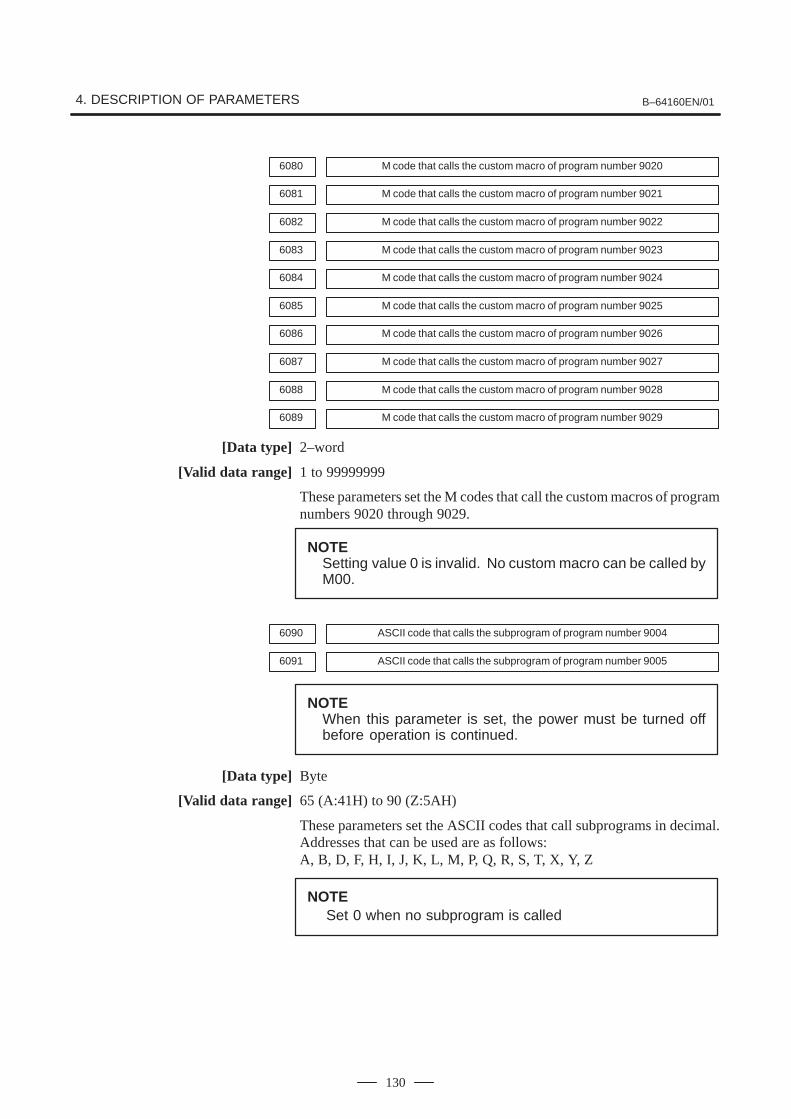
4. DESCRIPTION OF PARAMETERS B–64160EN/01
130
6080 M code that calls the custom macro of program number 9020
6081 M code that calls the custom macro of program number 9021
6082 M code that calls the custom macro of program number 9022
6083 M code that calls the custom macro of program number 9023
6084 M code that calls the custom macro of program number 9024
6085 M code that calls the custom macro of program number 9025
6086 M code that calls the custom macro of program number 9026
6087 M code that calls the custom macro of program number 9027
6088 M code that calls the custom macro of program number 9028
6089 M code that calls the custom macro of program number 9029
[Data type] 2–word
[Valid data range] 1 to 99999999
These parameters set the M codes that call the custom macros of programnumbers 9020 through 9029.
NOTESetting value 0 is invalid. No custom macro can be called byM00.
6090 ASCII code that calls the subprogram of program number 9004
6091 ASCII code that calls the subprogram of program number 9005
NOTEWhen this parameter is set, the power must be turned offbefore operation is continued.
[Data type] Byte
[Valid data range] 65 (A:41H) to 90 (Z:5AH)
These parameters set the ASCII codes that call subprograms in decimal.Addresses that can be used are as follows:A, B, D, F, H, I, J, K, L, M, P, Q, R, S, T, X, Y, Z
NOTESet 0 when no subprogram is called
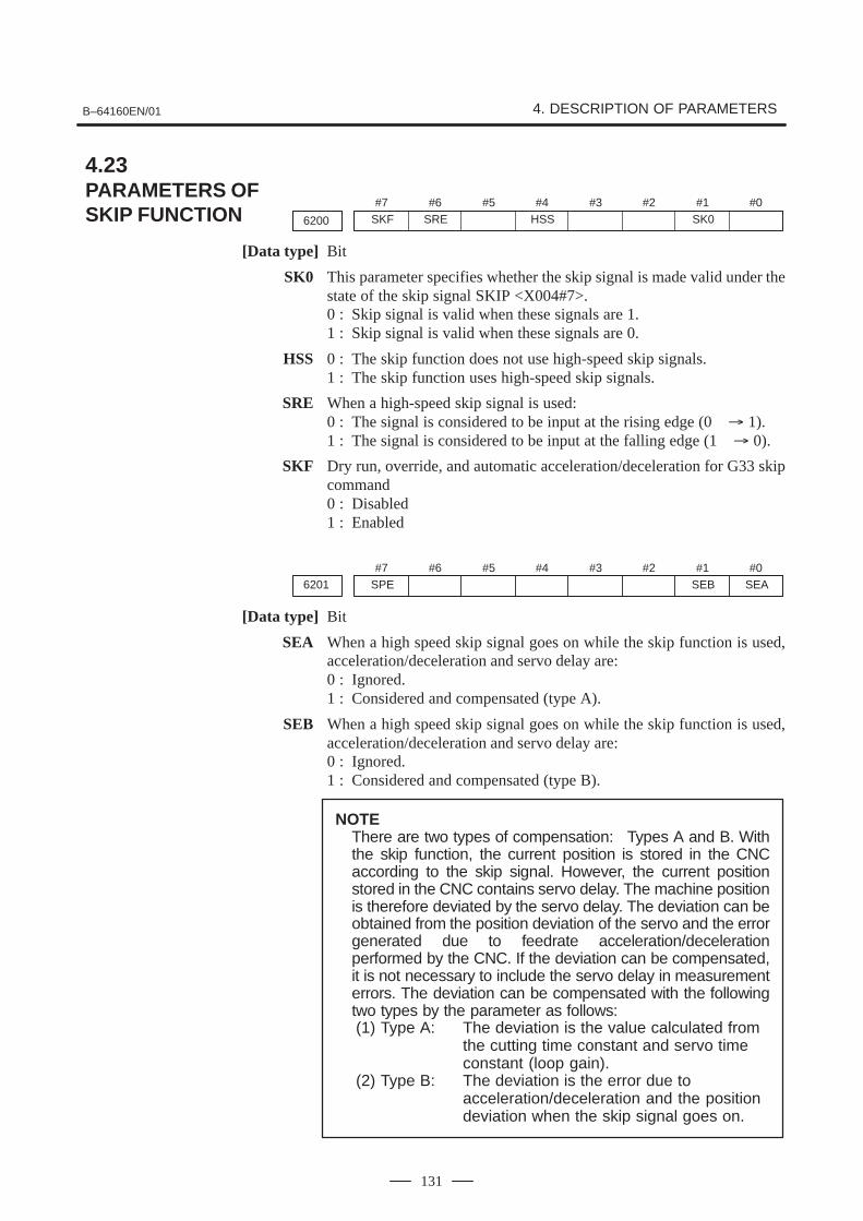
B–64160EN/01 4. DESCRIPTION OF PARAMETERS
131
#7
6200
#6SRE
#5 #4HSS
#3 #2 #1SK0
#0SKF
[Data type] Bit
SK0 This parameter specifies whether the skip signal is made valid under thestate of the skip signal SKIP <X004#7>.0 : Skip signal is valid when these signals are 1.1 : Skip signal is valid when these signals are 0.
HSS 0 : The skip function does not use high-speed skip signals.1 : The skip function uses high-speed skip signals.
SRE When a high-speed skip signal is used:0 : The signal is considered to be input at the rising edge (0 � 1).1 : The signal is considered to be input at the falling edge (1 � 0).
SKF Dry run, override, and automatic acceleration/deceleration for G33 skipcommand0 : Disabled1 : Enabled
#7SPE6201
#6 #5 #4 #3 #2 #1SEB
#0SEA
[Data type] Bit
SEA When a high speed skip signal goes on while the skip function is used,acceleration/deceleration and servo delay are:0 : Ignored.1 : Considered and compensated (type A).
SEB When a high speed skip signal goes on while the skip function is used,acceleration/deceleration and servo delay are:0 : Ignored.1 : Considered and compensated (type B).
NOTEThere are two types of compensation: Types A and B. Withthe skip function, the current position is stored in the CNCaccording to the skip signal. However, the current positionstored in the CNC contains servo delay. The machine positionis therefore deviated by the servo delay. The deviation can beobtained from the position deviation of the servo and the errorgenerated due to feedrate acceleration/decelerationperformed by the CNC. If the deviation can be compensated,it is not necessary to include the servo delay in measurementerrors. The deviation can be compensated with the followingtwo types by the parameter as follows:(1) Type A: The deviation is the value calculated from
the cutting time constant and servo time constant (loop gain).
(2) Type B: The deviation is the error due to acceleration/deceleration and the position deviation when the skip signal goes on.
4.23PARAMETERS OFSKIP FUNCTION

4. DESCRIPTION OF PARAMETERS B–64160EN/01
132
SPE For the skip function (G33), the skip signal (bit 7 of X004) is:0 : Disabled.1 : Enabled.
#7
6202
#6 #5 #4 #3 #2 #1 #01S1
[Data type] Bit
1S1 Specify high-speed skip signal (HDI0) is enabled when the G33 skipcommand is issued.
1S1 HDI0
NOTEHDI0 is high-speed skip signals.
#76210
#6 #5 #4 #3 #2 #1ROS
#0
[Data type] Bit
ROS When the skip position goes beyond the roll–over range, the values ofsystem variables #5061 through #5068 indicating the skip signal position:0 : Are not rolled over.1 : Are rolled over similar to the absolute coordinates.

B–64160EN/01 4. DESCRIPTION OF PARAMETERS
133
#7EEX6300
#6 #5 #4ESR
#3ESC
#2 #1 #0
[Data type] Bit
ESC When a reset is input between input of the external data input read signalESTB and execution of a search, the external program number searchfunction:0 : Performs a search.1 : Does not perform a search.
ESR External program number search0 : Disabled1 : Enabled
EEX PMC EXIN function0 : Conventional specifications1 : Extended specifications
If you want to handle data unavailable with the PMC/EXIN commandaccording to the conventional specifications, set this bit to 1.
For details of EXIN and how to change ladder software, refer to the PMCspecifications and other manuals.
4.24PARAMETERS OF EXTERNAL DATA INPUT/OUTPUT

4. DESCRIPTION OF PARAMETERS B–64160EN/01
134
6561 Standard color data for graphic color number 1
6562 Standard color data for graphic color number 2
6563 Standard color data for graphic color number 3
6564 Standard color data for graphic color number 4
6565 Standard color data for graphic color number 5
6566 Standard color data for graphic color number 6
6567 Standard color data for graphic color number 7
6568 Standard color data for graphic color number 8
6569 Standard color data for graphic color number 9
6570 Standard color data for graphic color number 10
6571 Standard color data for graphic color number 11
6572 Standard color data for graphic color number 12
6573 Standard color data for graphic color number 13
6574 Standard color data for graphic color number 14
6575 Standard color data for graphic color number 15
6581 Standard color data for character color number 1
6582 Standard color data for character color number 2
6583 Standard color data for character color number 3
6584 Standard color data for character color number 4
6585 Standard color data for character color number 5
6586 Standard color data for character color number 6
6587 Standard color data for character color number 7
6588 Standard color data for character color number 8
6589 Standard color data for character color number 9
6590 Standard color data for character color number 10
6591 Standard color data for character color number 11
6592 Standard color data for character color number 12
6593 Standard color data for character color number 13
6594 Standard color data for character color number 14
6595 Standard color data for character color number 15
[Data type] 2–word
[Unit of data] rr gg bb: 6–digit number (rr: Red gg: Green bb: Blue)When a number of less than six digits is set, the system assumes that 0 hasbeen specified for the unspecified higher digit(s).
4.25PARAMETERS OF GRAPHIC DISPLAY
B–64160EN/01 4. DESCRIPTION OF PARAMETERS
135
[Valid data range] Data of each color: 00 to 15 (same value as the tone level data on the colorsetting screen)When a value of more than 15 is set, the system assumes that 15 has beenspecified.
Example: Set 10203 in this parameter when the color tone levels are asfollows:Red: 1 Green: 2 Blue: 3
NOTETo set the color of the VGA display, use the color settingscreen. Note that the color changes when the settings ofparameters No.6561 through No.6595 are modified.
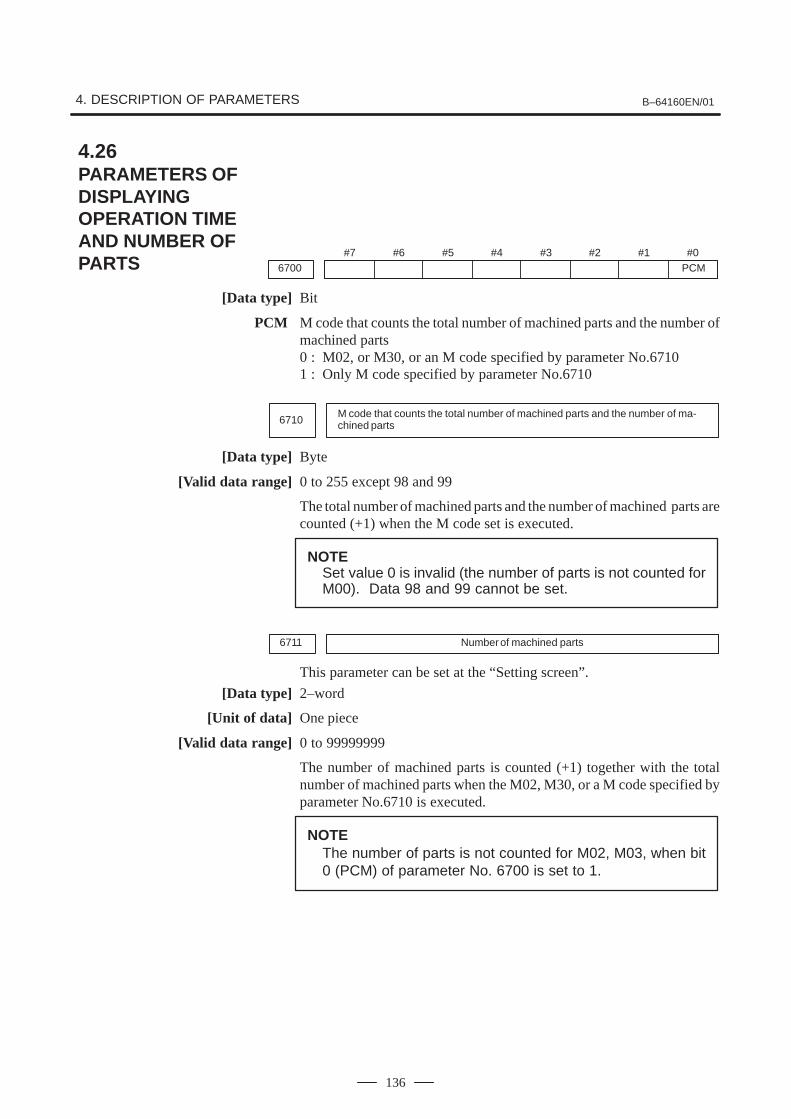
4. DESCRIPTION OF PARAMETERS B–64160EN/01
136
#76700
#6 #5 #4 #3 #2 #1 #0PCM
[Data type] Bit
PCM M code that counts the total number of machined parts and the number ofmachined parts0 : M02, or M30, or an M code specified by parameter No.67101 : Only M code specified by parameter No.6710
6710M code that counts the total number of machined parts and the number of ma-chined parts
[Data type] Byte
[Valid data range] 0 to 255 except 98 and 99
The total number of machined parts and the number of machined parts arecounted (+1) when the M code set is executed.
NOTESet value 0 is invalid (the number of parts is not counted forM00). Data 98 and 99 cannot be set.
6711 Number of machined parts
This parameter can be set at the “Setting screen”.
[Data type] 2–word
[Unit of data] One piece
[Valid data range] 0 to 99999999
The number of machined parts is counted (+1) together with the totalnumber of machined parts when the M02, M30, or a M code specified byparameter No.6710 is executed.
NOTEThe number of parts is not counted for M02, M03, when bit0 (PCM) of parameter No. 6700 is set to 1.
4.26PARAMETERS OF DISPLAYINGOPERATION TIME AND NUMBER OF PARTS

B–64160EN/01 4. DESCRIPTION OF PARAMETERS
137
6712 Total number of machined parts
This parameter can be set at the “Setting screen”.
[Data type] 2–word
[Unit of data] One piece
[Valid data range] 0 to 99999999
This parameter sets the total number of machined parts.
The total number of machined parts is counted (+1) when M02, M30, oran M code specified by parameter No.6710 is executed.
NOTEThe number of parts is not counted for M02, M03, when bit0 (PCM) of parameter No. 6700 is set to 1.
6713 Number of required parts
This parameter can be set at the “Setting screen”.
[Data type] Word
[Unit of data] One piece
[Valid data range] 0 to 9999
This parameter sets the number of required machined parts.
Required parts finish signal PRTSF is output to PMC when the number ofmachined parts reaches the number of required parts. The number of partsis regarded as infinity when the number of required parts is zero. ThePRTSF signal is then not output.
6750 Integrated value of power–on period
This parameter can be set at the “Setting screen”.
[Data type] 2–word
[Unit of data] One min
[Valid data range] 0 to 99999999
This parameter displays the integrated value of power–on period.
6751 Operation time (integrated value of time during automatic operation) I
This parameter can be set at the “Setting screen”.
[Data type] 2–word
[Unit of data] One ms
[Valid data range] 0 to 60000

4. DESCRIPTION OF PARAMETERS B–64160EN/01
138
6752 Operation time (integrated value of time during automatic operation) II
This parameter can be set at the “Setting screen”.
[Data type] 2–word
[Unit of data] One min
[Valid data range] 0 to 99999999
This parameter displays the integrated value of time during automaticoperation (neither stop nor hold time included).The actual time accumulated during operation is the sum of this parameterNo. 6751 and parameter No. 6752.
6753 Integrated value of cutting time I
This parameter can be set at the “Setting screen”.
[Data type] 2–word
[Unit of data] One ms
[Valid data range] 1 to 60000
6754 Integrated value of cutting time II
This parameter can be set at the “Setting screen”.
[Data type] 2–word
[Unit of data] One min
[Valid data range] 0 to 99999999
This parameter displays the integrated value of a cutting time that isperformed in cutting feed such as linear interpolation (G01) and circularinterpolation (G02 or G03).The actual time accumulated during cutting is the sum of this parameterNo. 6753 and parameter No. 6754.
6755Integrated value of general–purpose integrating meter drive signal (TMRON)ON time I
This parameter can be set at the “Setting screen”.
[Data type] 2–word
[Unit of data] One ms
[Valid data range] 0 to 60000
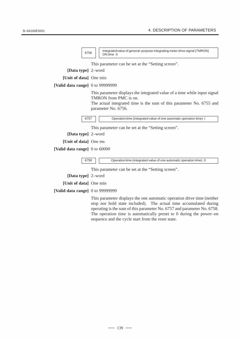
B–64160EN/01 4. DESCRIPTION OF PARAMETERS
139
6756Integrated value of general–purpose integrating meter drive signal (TMRON)ON time II
This parameter can be set at the “Setting screen”.
[Data type] 2–word
[Unit of data] One min
[Valid data range] 0 to 99999999
This parameter displays the integrated value of a time while input signalTMRON from PMC is on.The actual integrated time is the sum of this parameter No. 6755 andparameter No. 6756.
6757 Operation time (integrated value of one automatic operation time) I
This parameter can be set at the “Setting screen”.
[Data type] 2–word
[Unit of data] One ms
[Valid data range] 0 to 60000
6758 Operation time (integrated value of one automatic operation time) II
This parameter can be set at the “Setting screen”.
[Data type] 2–word
[Unit of data] One min
[Valid data range] 0 to 99999999
This parameter displays the one automatic operation drive time (neitherstop nor hold state included). The actual time accumulated duringoperating is the sum of this parameter No. 6757 and parameter No. 6758.The operation time is automatically preset to 0 during the power–onsequence and the cycle start from the reset state.

4. DESCRIPTION OF PARAMETERS B–64160EN/01
140
#7
6901
#6 #5 #4 #3 #2PCM
#1EPS
#0IGP
[Data type] Bit
IGP During follow–up for the absolute position detector, position switchsignals are:0 : Output1 : Not output
EPS The number of position switches is:0 : Up to 10.1 : Up to 16.
PCM Position switch signals are output:0 : Without considering acceleration/deceleration and servo delay.1 : With considering acceleration/deceleration and servo delay.
NOTEThe position switch signals are output consideringacceleration/deceleration after interpolation and servodelay. When this parameter is set to 1, however, signals areoutput from the position switches at different times from thespecified ones.
4.27PARAMETERS OF POSITION SWITCH FUNCTIONS

B–64160EN/01 4. DESCRIPTION OF PARAMETERS
141
6910 Axis corresponding to the first position switch
6911 Axis corresponding to the second position switch
6912 Axis corresponding to the third position switch
6913 Axis corresponding to the fourth position switch
6914 Axis corresponding to the fifth position switch
6915 Axis corresponding to the sixth position switch
6916 Axis corresponding to the seventh position switch
6917 Axis corresponding to the eighth position switch
6918 Axis corresponding to the ninth position switch
6919 Axis corresponding to the tenth position switch
6920 Axis corresponding to the eleventh position switch
6921 Axis corresponding to the twelveth position switch
6922 Axis corresponding to the thirteenth position switch
6923 Axis corresponding to the fourteenth position switch
6924 Axis corresponding to the fifteenth position switch
6925 Axis corresponding to the sixteenth position switch
[Data type] Byte
[Valid data range] 0 to Number of controlled axes
These parameters sequentially specify the numbers of the controlled axescorresponding to the 1st through 16th position switch functions. Thecorresponding position switch signal is output to the PMC when themachine coordinate of the corresponding axis is within the range set inparameters.
NOTESet 0 for the number corresponding to a position switchwhich is not to be used.

4. DESCRIPTION OF PARAMETERS B–64160EN/01
142
6930 Maximum operation range of the first position switch
6931 Maximum operation range of the second position switch
6932 Maximum operation range of the third position switch
6933 Maximum operation range of the fourth position switch
6934 Maximum operation range of the fifth position switch
6935 Maximum operation range of the sixth position switch
6936 Maximum operation range of the seventh position switch
6937 Maximum operation range of the eighth position switch
6938 Maximum operation range of the ninth position switch
6939 Maximum operation range of the tenth position switch
6940 Maximum operation range of the eleventh position switch
6941 Maximum operation range of the twelveth position switch
6942 Maximum operation range of the thirteenth position switch
6943 Maximum operation range of the fourteenth position switch
6944 Maximum operation range of the fifteenth position switch
6945 Maximum operation range of the sixteenth position switch
[Data type] 2–word
[Unit of data]
Increment system IS–A IS–B Unit
Metric machine 0.01 0.001 mm
Inch machine 0.001 0.0001 inch
Rotation axis 0.01 0.001 deg
[Valid data range] –99999999 to 99999999
These parameters sequentially set the maximum operation ranges of the1st through 16th position switches.

B–64160EN/01 4. DESCRIPTION OF PARAMETERS
143
6950 Minimum operation range of the first position switch
6951 Minimum operation range of the second position switch
6952 Minimum operation range of the third position switch
6953 Minimum operation range of the fourth position switch
6954 Minimum operation range of the fifth position switch
6955 Minimum operation range of the sixth position switch
6956 Minimum operation range of the seventh position switch
6957 Minimum operation range of the eighth position switch
6958 Minimum operation range of the ninth position switch
6959 Minimum operation range of the tenth position switch
6960 Minimum operation range of the eleventh position switch
6961 Minimum operation range of the twelveth position switch
6962 Minimum operation range of the thirteenth position switch
6963 Minimum operation range of the fourteenth position switch
6964 Minimum operation range of the fifteenth position switch
6965 Minimum operation range of the sixteenth position switch
[Data type] 2–word
[Unit of data]
Increment system IS–A IS–B Unit
Metric machine 0.01 0.001 mm
Inch machine 0.001 0.0001 inch
Rotation axis 0.01 0.001 deg
[Valid data range] –99999999 to 99999999
These parameters sequentially set the minimum operation ranges of the1st through 16th position switches.

4. DESCRIPTION OF PARAMETERS B–64160EN/01
144
#77100
#6 #5 #4HPF
#3HCL
#2 #1THD
#0JHD
[Data type] Bit
JHD Manual handle feed in JOG feed mode or incremental feed in the manualhandle feed0 : Invalid1 : Valid
When JHD:=0 When JHD:=1
JOG feedmode
Manual handlefeed mode
JOG feedmode
Manual handlefeed mode
JOG feed � � � �
Manual handle feed � � � �
Incremental feed � � � �
THD Manual pulse generator in TEACH IN JOG mode0 : Invalid1 : Valid
HCL The clearing of handle interruption amount display by soft key [CAN]operation is:0 : Disabled.1 : Enabled.
HPF When a manual handle feed exceeding the rapid traverse rate is issued,0 : The rate is clamped at the rapid traverse rate, and the handle pulses
corresponding to the excess are ignored. (The graduations of themanual pulse generator may not agree with the distance the machinehas traveled.)
1 : The rate is clamped at the rapid traverse rate, and the handle pulsescorresponding to the excess are not ignored, but stored in the CNC. (Ifthe rotation of the manual pulse generator is stopped, the machinemoves by the distance corresponding to the pulses preserved in theCNC, then stops.)
#77102
#6 #5 #4 #3 #2 #1 #0HNGx
[Data type] Bit axis
HNGx Axis movement direction for rotation direction of manual pulse generator0 : Same in direction1 : Reverse in direction
4.28PARAMETERS OF MANUAL HANDLE FEED AND HANDLE INTERRUPTION
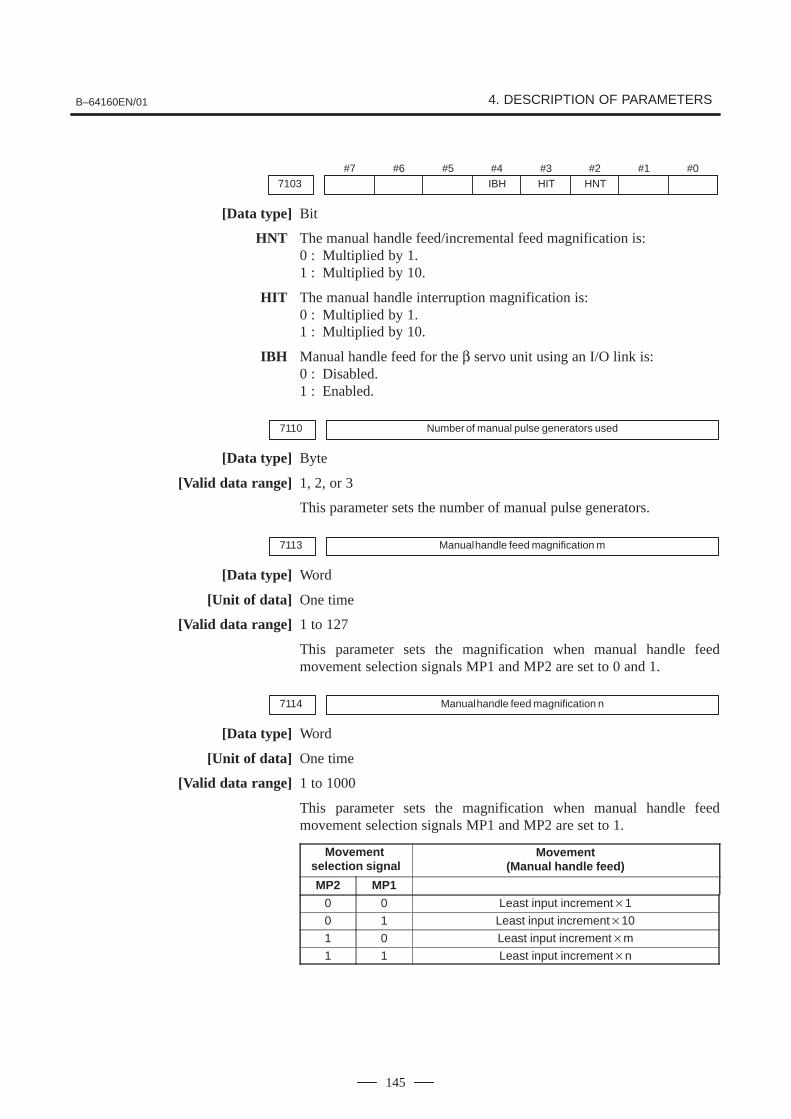
B–64160EN/01 4. DESCRIPTION OF PARAMETERS
145
#77103
#6 #5 #4IBH
#3HIT
#2HNT
#1 #0
[Data type] Bit
HNT The manual handle feed/incremental feed magnification is:0 : Multiplied by 1.1 : Multiplied by 10.
HIT The manual handle interruption magnification is:0 : Multiplied by 1.1 : Multiplied by 10.
IBH Manual handle feed for the β servo unit using an I/O link is:0 : Disabled.1 : Enabled.
7110 Number of manual pulse generators used
[Data type] Byte
[Valid data range] 1, 2, or 3
This parameter sets the number of manual pulse generators.
7113 Manual handle feed magnification m
[Data type] Word
[Unit of data] One time
[Valid data range] 1 to 127
This parameter sets the magnification when manual handle feedmovement selection signals MP1 and MP2 are set to 0 and 1.
7114 Manual handle feed magnification n
[Data type] Word
[Unit of data] One time
[Valid data range] 1 to 1000
This parameter sets the magnification when manual handle feedmovement selection signals MP1 and MP2 are set to 1.
Movement selection signal
Movement(Manual handle feed)
MP2 MP1
0 0 Least input increment�1
0 1 Least input increment�10
1 0 Least input increment�m
1 1 Least input increment�n

4. DESCRIPTION OF PARAMETERS B–64160EN/01
146
7117 Allowable number of pulses that can be accumulated during manual handle feed
[Data type] 2–Word
[Unit of data] Pulses
[Valid data range] 0 to 99999999
If manual handle feed is specified such that the rapid traverse rate will beexceeded momentarily, those pulses received from the manual pulsegenerator that exceed the rapid traverse rate are accumulated rather thancanceled. This parameter sets the maximum number of pulses which canbe accumulated in such a case.
NOTEIf the specification of manual handle feed is such that therapid traverse rate will be exceeded, for example, when themanual pulse generator is rotated at high speed with a largemagnification such as �100, the axial feedrate is clampedat the rapid traverse rate and those pulses received from themanual pulse generator that exceed the rapid traverse rateare ignored. In such a case, therefore, the scale on themanual pulse generator may differ from the actual amountof travel. If such a difference is not acceptable, thisparameter can be set to temporarily accumulate the excesspulses in the CNC, rather than ignoring them, up to thespecified maximum (pulses in excess of the set maximumare ignored). The accumulated pulses are output andconverted to a move command once the feedrate falls belowthe rapid traverse rate by reducing the rotational speed ofthe manual pulse generator or stopping its rotationaltogether. Note, however, that if the maximum number ofpulses to be accumulated is too large, stopping the rotationof the manual pulse generator does not stop feeding until thetool moves by an amount corresponding to the pulsesaccumulated in the CNC.

B–64160EN/01 4. DESCRIPTION OF PARAMETERS
147
#77200
#6OP7
#5OP6
#4OP5
#3OP4
#2OP3
#1OP2
#0OP1
[Data type] Bit
OP1 Mode selection on software operator’s panel0 : Not performed1 : Performed
OP2 JOG feed axis select and JOG rapid traverse buttons on softwareoperator’s panel0 : Not performed1 : Performed
OP3 Manual pulse generator’s axis select and manual pulse generator’smagnification switches on software operator’s panel0 : Not performed1 : Performed
OP4 JOG speed override and rapid traverse override switches on softwareoperator’s panel0 : Not performed1 : Performed
OP5 Optional block skip, single block, machine lock, and dry run switches onsoftware operator’s panel0 : Not performed1 : Performed
OP6 Protect key on software operator’s panel0 : Not performed1 : Performed
OP7 Feed hold on software operator’s panel0 : Not performed1 : Performed
#77201
#6 #5 #4 #3 #2 #1 #0JPC
[Data type] Bit
JPC For the name of a general–purpose switch function on the softwareoperator’s panel, the use of full–size characters is:0 : Not allowed.1 : Allowed.
4.29PARAMETERS OF SOFTWAREOPERATOR’S PANEL
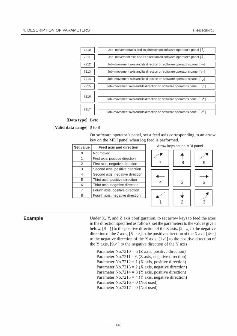
Arrow keys on the MDI panel
7 8 9
654
1 2 3
4. DESCRIPTION OF PARAMETERS B–64160EN/01
148
7210 Job–movement axis and its direction on software operator’s panel �↑�
7211 Job–movement axis and its direction on software operator’s panel �↓�
7212 Job–movement axis and its direction on software operator’s panel �→�
7213 Job–movement axis and its direction on software operator’s panel �←�
7214 Job–movement axis and its direction on software operator’s panel � �
7215 Job–movement axis and its direction on software operator’s panel � �
7216Job–movement axis and its direction on software operator’s panel � �
7217Job–movement axis and its direction on software operator’s panel � �
[Data type] Byte
[Valid data range] 0 to 8
On software operator’s panel, set a feed axis corresponding to an arrowkey on the MDI panel when jog feed is performed.
Set value Feed axis and direction
0 Not moved
1 First axis, positive direction
2 First axis, negative direction
3 Second axis, positive direction
4 Second axis, negative direction
5 Third axis, positive direction
6 Third axis, negative direction
7 Fourth axis, positive direction
8 Fourth axis, negative direction
Under X, Y, and Z axis configuration, to set arrow keys to feed the axesin the direction specified as follows, set the parameters to the values givenbelow. [8 ] to the positive direction of the Z axis, [2 ] to the negativedirection of the Z axis, [6 �] to the positive direction of the X axis [4�]to the negative direction of the X axis, [1�] to the positive direction ofthe Y axis, [9 ] to the negative direction of the Y axis
Parameter No.7210 = 5 (Z axis, positive direction)Parameter No.7211 = 6 (Z axis, negative direction)Parameter No.7212 = 1 (X axis, positive direction)Parameter No.7213 = 2 (X axis, negative direction)Parameter No.7214 = 3 (Y axis, positive direction)Parameter No.7215 = 4 (Y axis, negative direction)Parameter No.7216 = 0 (Not used)Parameter No.7217 = 0 (Not used)
Example

B–64160EN/01 4. DESCRIPTION OF PARAMETERS
149
7220 Name of general–purpose switch on software operator’s panel
7283 Name of general–purpose switch on software operator’s panel
[Data type] Byte
OPERATOR’S PANEL O1234 N5678
SIGNAL1 : OFF ONSIGNAL2 : OFF ONSIGNAL3 : OFF ONSIGNAL4 : OFF ONSIGNAL5 : OFF ONSIGNAL6 : OFF ONSIGNAL7 : OFF ONSIGNAL8 : OFF ON
These names are set using character codes that are displayed in parameterNos. 7220 to 7283.
Parameter No.7220:Sets the character code (083) corresponding to S of SIGNAL 1.
Parameter No.7221:Sets the character code (073) corresponding to I of SIGNAL 1.
Parameter No.7222:Sets the character code (071) corresponding to G of SIGNAL 1.
Parameter No.7223:Sets the character code (078) corresponding to N of SIGNAL 1.
Parameter No.7224:Sets the character code (065) corresponding to A of SIGNAL 1.
Parameter No.7225:Sets the character code (076) corresponding to L of SIGNAL 1.
Parameter No.7226:Sets the character code (032) corresponding to (space) of SIGNAL 1.
Parameter No.7227:Sets the character code (049) corresponding to 1 of SIGNAL 1.
Parameter Nos. 7228 to 7235:Set the character codes of SIGNAL 2 shown in the figure above.
Parameter Nos. 7236 to 7243:Set the character codes of SIGNAL 3 shown in the figure above.
Parameter Nos. 7244 to 7251:Set the character codes of SIGNAL 4 shown in the figure above.
Parameter Nos. 7252 to 7259:Set the character codes of SIGNAL 5 shown in the figure above.
Parameter Nos. 7260 to 7267:Set the character codes of SIGNAL 6 shown in the figure above.
Parameter Nos. 7268 to 7275:Set the character codes of SIGNAL 7 shown in the figure above.
Parameter Nos. 7276 to 7283:Set the character codes of SIGNAL 8 shown in the figure above.
The character codes are shown in Appendix A CHARACTER CODELIST.
ExampleThese parameters set thenames of thegeneral–purpose switches(SIGNAL 1 throughSIGNAL 8) on thesoftware operator’s panelas described below.

4. DESCRIPTION OF PARAMETERS B–64160EN/01
150
#7SKE8001
#6AUX
#5NCC
#4 #3RDE
#2OVE
#1 #0MLE
[Data type] Bit
MLE Whether all axis machine lock signal MLK is valid for PMC–controlledaxes0 : Valid1 : Invalid
NOTEEach–axis machine lock signals MLK1 to MLK4 are alwaysvalid, regardless of the setting of this parameter.
OVE Signals related to dry run and override used in PMC axis control0: Same signals as those used for the CNC
(1) Feedrate override signals *FV0 to *FV7(2) Override cancellation signal OVC(3) Rapid traverse override signals ROV1 and ROV2(4) Dry run signal DRN(5) Rapid traverse selection signal RT
1: Signals specific to the PMC(1) Feedrate override signals *FV0E to *FV7E(2) Override cancellation signal OVCE(3) Rapid traverse override signals ROV1E and ROV2E(4) Dry run signal DRNE(5) Rapid traverse selection signal RTE
RDE Whether dry run is valid for rapid traverse in PMC axis control0 : Invalid1 : Valid
NCC When a travel command is issued for a PMC–controlled axis (selected bya controlled–axis selection signal) according to the program:0 : P/S alarm 139 is issued while the PMC controls the axis with an axis
control command. While the PMC does not control the axis, a CNCcommand is enabled.
1 : P/S alarm 139 is issued unconditionally.
AUX The number of bytes for the code of an auxiliary function (12H) commandto be output is0 : 1 (0 to 255)1 : 2 (0 to 65535)
SKE Skip signal during axis control by the PMC0 : Uses the same signal SKIP (X004#7) as CNC.1 : Uses dedicated axis control signal ESKIP (X004#6) used by the
PMC.
4.30PARAMETERS OF AXIS CONTROL BY PMC

B–64160EN/01 4. DESCRIPTION OF PARAMETERS
151
#78002
#6 #5PF2
#4PF1
#3F10
#2SUE
#1 #0RPD
[Data type] Bit
RPD Rapid traverse rate for PMC–controlled axes0 : Feedrate specified with parameter No.14201 : Feedrate specified with the feedrate data in an axis control command
SUE Whether acceleration/deceleration is performed for an axis that issynchronized with external pulses, for external pulse synchronizationcommands in PMC axis control0 : Performed (exponential acceleration/deceleration)1 : Not performed
F10 Least increment for the feedrate for cutting feed (per minute) in PMC axiscontrol
F10 Millimeter input Inch input0 1 mm/min 0.01 inch/min
1 10 mm/min 0.1 inch/min
PF1, PF2 Set the the feedrate unit of feed per minute in PMC axis control
PF2 PF1 Feedrate unit0 0 1/1
0 1 1/10
1 0 1/100
1 1 1/1000
#78003
#6 #5 #4 #3 #2 #1PAX
#0PIM
NOTEWhen this parameter is set, the power must be turned offbefore operation is continued.
[Data type] Bit
PIM Specifies whether to cause an inch/metric input to affect the linear axisthat is subjected only to PMC axis control (see the parameter No.1010), asfollows:0: To affect.1: Not to affect.
PAX When the number of CNC–controlled axes (parameter No. 1010) is set to0:0 : All axes are assumed to be CNC axes.1 : All axes are assumed to be PMC axes.

4. DESCRIPTION OF PARAMETERS B–64160EN/01
152
#78004
#6NCI
#5DSL
#4 #3 #2 #1NMT
#0CMV
CMV When a move command and auxiliary function are specified from theCNC, and the system is awaiting the auxiliary function completion signalafter completion of the specified axis movement:0 : An alarm (No.130) is issued when an axis control command is issued
from the PMC for the same axis.1 : An axis control command, when issued from the PMC for the same
axis, is executed.
NMT When a command is specified from the CNC for the axis on which the toolis moving according to axis control specification from the PMC:0 : P/S alarm No.130 is issued.1 : The command is executed without issuing an alarm, provided the
command does not involve a movement on the axis.
DSL If the selection of an axis is changed when PMC axis selection is disabled:0 : P/S alarm No.139 is issued.1 : The change is valid, and no alarm is issued for an unspecified system.
NCI In axis control by the PMC, a position check at the time of deceleration is:0 : Performed.1 : Not performed.
#7MFD8005
#6 #5IFV
#4 #3 #2R10
#1 #0EDC
[Data type] Bit
EDC In PMC–based axis control, an external deceleration signal is:0 : Disabled.1 : Enabled.
R10 When the RPD parameter (bit 0 of parameter No.8002) is set to 1, the unitfor specifying a rapid traverse rate for the PMC axis is:0 : 1 mm/min.1 : 10 mm/min.
IFV Override for each group in PMC axis control is:0 : Disabled.1 : Enabled.
MFD Output by each auxiliary function of the PMC axis control function is:0 : Disabled.1 : Enabled.

B–64160EN/01 4. DESCRIPTION OF PARAMETERS
153
#78006
#6 #5 #4 #3 #2IPA
#1EML
#0
[Data type] Bit
EML When bit 0 (MLE) of parameter No. 8001 is set to 1, for PMC axes:0 : The all axis machine lock signal and axis–by–axis machine lock
signals are disabled.1 : The all axis machine lock signal is disabled and the axis–by–axis
machine lock signals are enabled.
IPA For controlled axis at PMC axis control only (see the parameter No.1010) :0 : The in–position check is performed when no move command is
issued for the PMC axis.1 : No in–position check is always performed.
#78008
#6 #5 #4 #3 #2 #1 #0MIRx
[Data type] Bit axis
MIRx When a PMC axis control command is issued in mirror image mode, themirror image is:0 : Not considered.1 : Considered.
This parameter is valid when PMC signals MI1 to MI4 <bits 0 to 3 ofG106> are set to “1” or bit 0 (MIRx) of parameter No. 0012 is set to “1”.
8010 Selection of the DI/DO group for each axis controlled by the PMC
[Data type] Byte axis
[Valid data range] 1 to 4
Specify the DI/DO group to be used to specify a command for eachPMC–controlled axis.
Value Description1 DI/DO group A (G142 to G153) is used.
2 DI/DO group B (G154 to G165) is used.
3 DI/DO group C (G166 to G177) is used.
4 DI/DO group D (G178 to G189) is used.
8020 Low–speed feedrate at reference position return in axis control by PMC (FL)
[Data type] Word axis
[Unit of data, Valid data range]
Increment system Unit of dataValid data range
Increment system Unit of dataIS–A, IS–B
Millimeter machine 1 mm/min 6 to 15000
Inch machine 0.1 inch/min 6 to 6000
Rotation axis 1 deg/min 6 to 15000
This parameter specifies the low–speed feedrate at a reference positionreturn on a PMC–controlled axis (FL).

4. DESCRIPTION OF PARAMETERS B–64160EN/01
154
NOTEIf 0 is specified, the value of parameter No. 1425 is used.
8021 Minimum speed of rapid traverse override in axis control by PMC (Fo)
[Data type] Word axis
[Unit of data, Valid data range]
Increment system Unit of dataValid data range
Increment system Unit of dataIS–A, IS–B
Millimeter machine 1 mm/min 6 to 15000
Inch machine 0.1 inch/min 6 to 6000
Rotation axis 1 deg/min 6 to 15000
This parameter specifies the minimum speed of rapid traverse override ona PMC–controlled axis (Fo).
8028 Linear acceleration/deceleration time constant for speed commands for PMC axis control
[Data type] Word axis[Unit of data] ms/1000 min-1
[Valid data range] 0 to 32767
This parameter sets the time required for the servo motor rotation speedto increase or decrease by 1000 min–1, for each axis, as a linearacceleration/deceleration time constant for speed commands for PMCaxis control.
NOTEIf this parameter is set to 0, acceleration/deceleration controlis not applied.
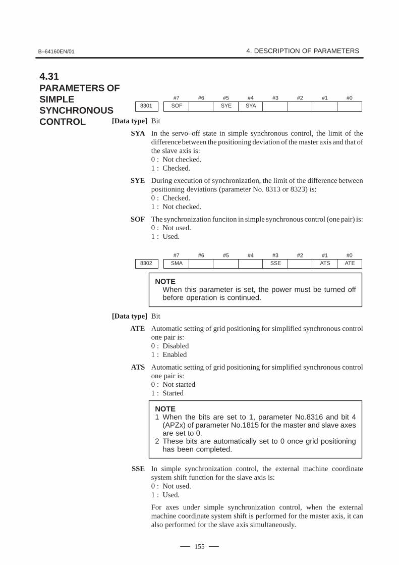
B–64160EN/01 4. DESCRIPTION OF PARAMETERS
155
#7SOF8301
#6 #5SYE
#4SYA
#3 #2 #1 #0
[Data type] Bit
SYA In the servo–off state in simple synchronous control, the limit of thedifference between the positioning deviation of the master axis and that ofthe slave axis is:0 : Not checked.1 : Checked.
SYE During execution of synchronization, the limit of the difference betweenpositioning deviations (parameter No. 8313 or 8323) is:0 : Checked.1 : Not checked.
SOF The synchronization funciton in simple synchronous control (one pair) is:0 : Not used.1 : Used.
#7SMA8302
#6 #5 #4 #3SSE
#2 #1ATS
#0ATE
NOTEWhen this parameter is set, the power must be turned offbefore operation is continued.
[Data type] Bit
ATE Automatic setting of grid positioning for simplified synchronous controlone pair is:0 : Disabled1 : Enabled
ATS Automatic setting of grid positioning for simplified synchronous controlone pair is:0 : Not started1 : Started
NOTE1 When the bits are set to 1, parameter No.8316 and bit 4
(APZx) of parameter No.1815 for the master and slave axesare set to 0.
2 These bits are automatically set to 0 once grid positioninghas been completed.
SSE In simple synchronization control, the external machine coordinatesystem shift function for the slave axis is:0 : Not used.1 : Used.
For axes under simple synchronization control, when the externalmachine coordinate system shift is performed for the master axis, it canalso performed for the slave axis simultaneously.
4.31PARAMETERS OF SIMPLESYNCHRONOUSCONTROL
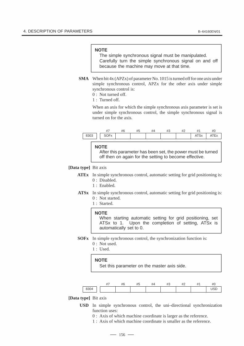
4. DESCRIPTION OF PARAMETERS B–64160EN/01
156
NOTEThe simple synchronous signal must be manipulated.Carefully turn the simple synchronous signal on and offbecause the machine may move at that time.
SMA When bit 4x (APZx) of parameter No. 1015 is turned off for one axis undersimple synchronous control, APZx for the other axis under simplesynchronous control is:0 : Not turned off.1 : Turned off.
When an axis for which the simple synchronous axis parameter is set isunder simple synchronous control, the simple synchronous signal isturned on for the axis.
#7SOFx8303
#6 #5 #4 #3 #2 #1ATSx
#0ATEx
NOTEAfter this parameter has been set, the power must be turnedoff then on again for the setting to become effective.
[Data type] Bit axis
ATEx In simple synchronous control, automatic setting for grid positioning is:0 : Disabled.1 : Enabled.
ATSx In simple synchronous control, automatic setting for grid positioning is:0 : Not started.1 : Started.
NOTEWhen starting automatic setting for grid positioning, setATSx to 1. Upon the completion of setting, ATSx isautomatically set to 0.
SOFx In simple synchronous control, the synchronization function is:0 : Not used.1 : Used.
NOTESet this parameter on the master axis side.
#78304
#6 #5 #4 #3 #2 #1 #0USD
[Data type] Bit axis
USD In simple synchronous control, the uni–directional synchronizationfunction uses:0 : Axis of which machine coordinate is larger as the reference.1 : Axis of which machine coordinate is smaller as the reference.

B–64160EN/01 4. DESCRIPTION OF PARAMETERS
157
NOTESet this parameter (USD) to the same value for both themaster and slave axes.
#78305
#6 #5 #4 #3 #2 #1USE
#0USC
[Data type] Bit
USC In simple synchronous control, the uni–directional synchronizationfunction is:0 : Not used.1 : Used.
NOTEThis parameter is valid only when bit 7 (SOF) of parameterNo. 8301 or bit 7 (SOFx) of parameter No. 8303 is set to 1.
USE In simple synchronous control, after emergency stop, the uni–directionalsynchronization function is:0 : Used.1 : Not used.
NOTEThis parameter is valid only when bit 7 (SOF) of parameterNo. 8301 or bit 7 (SOFx) of parameter No. 8303 is set to 1.
8311 Axis number of master axis in synchronous control
NOTEWhen this parameter is set, the power must be turned offbefore operation is continued.
[Data type] Byte axis
[Valid data range] 0, 1 to Number of controlled axes
Select a master axis and slave axis in simple synchronous control. Set amaster axis number with the slave axis side. The axis number settings are:1 –> First axis, 2 –> Second axis, 3 –> Third axis, 4 –> Fourth axis. Up totwo pairs can be specified.
Example1:Simple synchronous control is exercised with one pair.When using the first axis (X–axis) as the master axis, and thethird axis (Z–axis) as the slave axis, set parameter No.8311 asfollows:
Parameter No. 8311 X (first axis) = 0Y (second axis) = 0Z (third axis) = 1A (fourth axis) = 0

4. DESCRIPTION OF PARAMETERS B–64160EN/01
158
Example2:Simple synchronous control is exercised with two pairs.Assume that the following three pairs are to be used:The master axis is the first axis, while a slave axis is the fouth axis.The master axis is the second axis, while a slave axis is the thirdaxis.For this specification, set this parameter as follows:
Parameter No.8311 X (First axis) = 0Y (Second axis) = 0Z (Third axis) = 2
(Fourth axis) = 1
NOTE1 In Example 2 above, the Z axis, which is the master axis, is
used as the slave axis of another axis. This usage mayprevent other functions from operating normally. Whenexercising simple synchronous control with two pairs, takecare.
2 The axis number of a master axis must always be smallerthan the corresponding slave axis number. Multiple slaveaxes cannot be assigned to a master axis.
8313Limit of the difference between the amount of positioning deviation of the masterand slave axes (Synchronous control one pair)
[Data type] Word
[Unit of data] Detection unit
[Valid data range] 0 to 32767
Set the limit of the difference between the amount of positioningdeviation of the master and slave (fourth) axes. If the difference betweenthem exceeds the limit assigned to the parameter, the P/S alarm (No.213)is activated.
8314 Maximum error in synchronization error check
[Data type] Word axis
[Unit of data]Increment system IS–A IS–B UnitsMillimeter machine 0.01 0.001 mm
Inch machine 0.001 0.0001 inch
Rotation axis 0.01 0.001 deg
[Valid data range] 0 to 32767
The machine coordinates on a master axis and slave axis are monitored. Ifa difference (synchronization error) which is greater than the valuespecified in this parameter is detected, a servo alarm (No.407) isgenerated, and the machine is stopped.
Set this parameter with a master axis. When 0 is set in this parameter, nosynchronization error check is made.

B–64160EN/01 4. DESCRIPTION OF PARAMETERS
159
8315 Maximum compensation value for synchronization (Synchronous control one pair)
NOTEWhen this parameter is set, the power must be turned offbefore operation is continued.
[Data type] Word
[Unit of data] Detection unit
[Valid data range] 0 to 32767
This parameter sets the maximum compensation value forsynchronization. When a compensation value greater than the value setin this parameter is used, servo alarm No.410 of slave axis is issued.
8316Difference between reference counters for master and slave axes (Synchronous control one pair)
NOTEWhen this parameter is set, the power must be turned offbefore operation is continued.
[Data type] 2–word
[Data unit] Detection unit
[Valid data range] –99999999 to 99999999
This parameter indicates the difference between the values in thereference counter for the master axis and that for the slave axis.
NOTEOnce grid positioning has been completed, the differencebetween the reference counters is automatically set in thisparameter. At this time, bit 1 (ATS) of parameter No.8302 isset to 0.
8317 Torque difference alarm detection time (Synchronous control one pair)
[Data type] Word
[Data unit] ms
[Valid data range] 0 to 4000 (When 0 is set, 512 ms is assumed.)
This parameter specifies the period between the servo preparationcompletion signal (SA <F000 bit 6>) being set to 1 and the check of thetorque difference alarm being started, for the torque difference alarmdetection function.
The set value is rounded up to the nearest a multiple of 16 ms.
[Example]When 100 is specified, 112 ms is assumed.

4. DESCRIPTION OF PARAMETERS B–64160EN/01
160
8318Detection timer for the limit of the difference between the positioning deviation ofthe master axis and that of the slave axis
[Data type] Word
[Unit of data] 8m
[Valid data range] 0 to 1000
This parameter sets the time from the output of a compensation pulse tothe slave axis to the start of the check of the limit of the difference betweenthe positioning deviation of the master axis and that of the slave axis bythe synchronization function. The setting is also used for the check of anexcessive error at stop.
NOTEIf a value greater than 1000 is set, a value of 1000 isassumed.
8323 Maximum allowable difference between master axis and slave axis positional deviations
[Data type] Word axis
[Unit of data] Detection unit
[Valid data range] 0 to 32767
This parameter sets the maximum allowable difference between themaster axis and slave axis position deviations. If a positional deviationdifference exceeds the value specified in this parameter, an alarm(No.213) is issued.
Set this parameter with a master axis. If 0 is specified in this parameter, noposition deviation difference check is made.
8325 Maximum compensation value for synchronization
[Data type] Word axis
[Unit of data] Detection unit
[Valid data range] 0 to 32767
This parameter sets the maximum compensation value forsynchronization. If a compensation value exceeds the value specifiedwith this parameter, a servo alarm (No.407) is issued.
Specify a master axis for this parameter. To enable this parameter, set theSOFx parameter (bit 7 of parameter No.8303) to 1.

B–64160EN/01 4. DESCRIPTION OF PARAMETERS
161
8326 Difference between master axis and slave axis reference counters
[Data type] 2–word axis
[Unit of data] Detection unit
[Valid data range] –99999999 to 99999999
The difference between the master axis reference counter and slave axisreference counter (master axis and slave axis grid shift) is automaticallyset when automatic setting for grid positioning is performed. Then, thedifference is transferred together with an ordinary grid shift value to theservo system when the power is turned on.
This parameter is set with a master axis.
8327 Torque difference alarm detection timer
[Data type] Word axis
[Unit of data] ms
[Valid data range] 0 to 4000
This parameter sets a time from the servo preparation completion signal,SA (F000#6), being set to 1 until torque difference alarm detection isstarted in simple synchronous control. A fraction of less than 16 msec isrounded up.
Example: Setting = 100: The specification of 112 msec is assumed.
Set this parameter with a master axis. If 0 is set in this parameter, thespecification of 512 msec is assumed.

4. DESCRIPTION OF PARAMETERS B–64160EN/01
162
8341 Program number subject to check termination
[Data type] Word
[Valid data range] 0 to 9999
This parameter sets the program number, including a sequence number,subject to sequence number check termination. Parameter No.8342 isused to set a sequence number subject to check termination.
NOTEA program number can also be set on the setting screen. Ifa program number is set on the setting screen, the value ofthe parameter is changed accordingly.
8342 Sequence number subject to check termination
[Data type] 2–word
[Valid data range] 0 to 9999
This parameter sets the sequence number subject to sequence numbercheck termination. If the block containing the sequence number set with this parameter isexecuted while the program set with parameter No.8341 is beingexecuted, a single block stop occurs after the block is executed. At thistime, the setting is automatically set to –1.
NOTEA sequence number can also be set by using the settingscreen. If a sequence number is set on the setting screen,the value of the parameter is changed accordingly.
4.32PARAMETERS OFSEQUENCE NUMBERCOMPARISON ANDSTOP

B–64160EN/01 4. DESCRIPTION OF PARAMETERS
163
8130 Number of total controlled axes
NOTEWhen this parameter is set, the power must be turned offbefore operation is continued.
[Data type] Byte
[Valid data range] 2 to 4Set the total number of CNC controlled axes.
#7
8131
#6 #5 #4 #3AOV
#2EDC
#1 #0HPG
NOTEWhen this parameter is set, the power must be turned offbefore operation is continued.
[Data type] Bit
HPG Manual handle feed is0 : Not used.1 : Used.
EDC External deceleration is0 : Not used.1 : Used.
AOV Automatic corner override is0 : Not used.1 : Used.
#7
8132
#6 #5SCL
#4 #3 #2BCD
#1 #0
NOTEWhen this parameter is set, the power must be turned offbefore operation is continued.
[Data type] Bit
BCD Second auxiliary function is0 : Not used.1 : Used.
SCL Scaling is0 : Not used.1 : Used.
4.33PARAMETERS OFFS0i BASICFUNCTIONS

4. DESCRIPTION OF PARAMETERS B–64160EN/01
164
#78134
#6 #5 #4 #3 #2 #1 #0IAP
NOTEWhen this parameter is set, the power must be turned offbefore operation is continued.
[Data type] Bit
IAP Conversational programming with graphic function is0 : Not used.1 : Used.
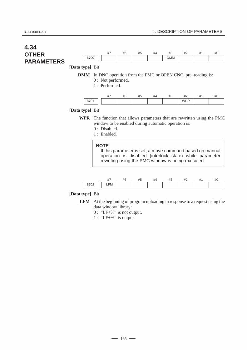
B–64160EN/01 4. DESCRIPTION OF PARAMETERS
165
#78700
#6 #5 #4 #3DMM
#2 #1 #0
[Data type] Bit
DMM In DNC operation from the PMC or OPEN CNC, pre–reading is:0 : Not performed.1 : Performed.
#78701
#6 #5 #4 #3 #2WPR
#1 #0
[Data type] Bit
WPR The function that allows parameters that are rewritten using the PMCwindow to be enabled during automatic operation is:0 : Disabled.1 : Enabled.
NOTEIf this parameter is set, a move command based on manualoperation is disabled (interlock state) while parameterrewriting using the PMC window is being executed.
#7LFM8702
#6 #5 #4 #3 #2 #1 #0
[Data type] Bit
LFM At the beginning of program uploading in response to a request using thedata window library:0 : “LF+%” is not output.1 : “LF+%” is output.
4.34OTHERPARAMETERS

4. DESCRIPTION OF PARAMETERS B–64160EN/01
166
#78706
#6 #5 #4 #3 #2 #1NWD
#0HSD
NOTEWhen this parameter has been set, the power must beturned off before operation is contimued.
[Data type] Bit
HSD Main machining during DNC operation with FOCAS1/HSSB is:0 : Normal operation.1 : High–speed operation.
Set this parameter according to machining during DNC operation.Usually, when binary operation and programs containing contiguoussmall blocks are performed during DNC operation with FOCAS1/HSSB,high–speed operation is selected.
NOTEFor details of this parameter, also refer to “FANUC OpenCNC DNC Operation Management Package” and othermanuals.
NWD During DNC operation with FOCAS1/HSSB, new DNC functions are:0 : Not executed.1 : Executed.
When this parameter is set, the M198 command (subprogram call) canalso be executed with FOCAS1/HSSB.
NOTETo execute the M198 command with FOCAS1/HSSB,parameter No. 20 must be set to “15”.
For details of this parameter, also refer to “FANUC OpenCNC DNC Operation Management Package” and othermanuals.

B–64160EN/01 4. DESCRIPTION OF PARAMETERS
167
8760 Program number for data registration (data input/output function using theI/O link)
[Data type] Word
[Valid data range] 0 to 9999
When the data input/output function using the I/O link is used, thisparameter sets the program numbers of the programs to be used forregistering data (parameters, macro variables, and diagnostic data) fromPower Mates.
For a Power Mate in group n, the following program numbers are used:For parameters: Setting + n � 10 + 0For macro variables: Setting + n � 10 + 1For diagnostic data: Setting + n � 10 + 2
Example: When 8000 is set
8000: Parameters of group 0 (I/O channel = 20)8001: Macro variables of group 0 (I/O channel = 20)8002: Diagnostic data of group 0 (I/O channel = 20)8010: Parameters of group 1 (I/O channel = 21)8011: Macro variables of group 1 (I/O channel = 21)8012: Diagnostic data of group 1 (I/O channel = 21)8020: Parameters of group 2 (I/O channel = 22)8021: Macro variables of group 2 (I/O channel = 22)8022: Diagnostic data of group 2 (I/O channel = 22)
8150: Parameters of group 15 (I/O channel = 35)8151: Macro variables of group 15 (I/O channel = 35)8152: Diagnostic data of group 15 (I/O channel = 35)
NOTEWhen 0 is set, the input/output of parameters, macrovariables, and diagnostic data cannot be performed, butprogram input/output processing is performed.
8790 Timing for executing an auxiliary macro
[Data type] Word
This parameter sets the timing for executing a macro executor auxiliarymacro while NC programs, offset data, and so forth are being read orpunched out.
When as many characters as the number specified with this parameter areread or punched out, an auxiliary macro is executed once. When 0 is set inthis parameter, no auxiliary macro is executed during read or punchprocessing.

4. DESCRIPTION OF PARAMETERS B–64160EN/01
168
#78801
#6 #5 #4 #3 #2 #1 #0
[Data type] Bit
Bit parameter 1 for machine tool builder
#78802
#6 #5 #4 #3 #2 #1 #0
[Data type] Bit
Bit parameter 2 for machine tool builder
NOTEThese parameters are used only by the machine tool builder.Refer to the relevant manual supplied by the machine toolbuilder for details.
8811 2–word parameter 1 for machine tool builder
8812 2–word parameter 2 for machine tool builder
8813 2–word parameter 3 for machine tool builder
[Data type] 2–word
[Valid data range] –99999999 to 99999999
NOTEThese parameters are used only by the machine tool builder.Refer to the relevant manual supplied by the machine toolbuilder for details.

B–64160EN/01 4. DESCRIPTION OF PARAMETERS
169
#78901
#6 #5 #4 #3 #2 #1 #0FAN
[Data type] Bit
FAN A fan motor error is:0 : Detected. (When the fan motor error is detected, an overheating alarm
occurs.)1 : Not detected. (Use inhibited)
#78903
#6 #5 #4 #3 #2 #1 #0PRM
[Data type] Bit
PRM A periodic maintenance expiration message is:0 : Not displayed.1 : Displayed.
8911 Ratio of the items on the periodic maintenance screen to the respective lives
[Data type] Byte
[Unit of data] 1%
[Valid data range] 0 to 100
On the periodic maintenance screen, if the remaining time of an item fallsto a value less than the percentage of the life specified in this parameter,the remaining time is displayed in red as a warming.
8940 Title character code 1
8941 Title character code 2
:
8949 Title character code 10
[Data type] Byte
[Valid data range] See below.
When the CNC is turned on, up to ten characters specified in theseparameters are displayed on the screen showing the series and edition ofthe CNC.
� The following characters can be used.0 to 9, A to Z, – (minus sign), . (period), and space
� The character codes to be specified are listed in the character code listin Appendix A.
� If any code other than those character codes that can be specified isspecified, a space is displayed.
4.35PARAMETERS OF MAINTENANCE

4. DESCRIPTION OF PARAMETERS B–64160EN/01
170
12801 Number of a signal symbol table for selecting an operation history signal (01)
12802 Number of a signal symbol table for selecting an operation history signal (02)
12803 Number of a signal symbol table for selecting an operation history signal (03)
12804 Number of a signal symbol table for selecting an operation history signal (04)
12805 Number of a signal symbol table for selecting an operation history signal (05)
12806 Number of a signal symbol table for selecting an operation history signal (06)
12807 Number of a signal symbol table for selecting an operation history signal (07)
12808 Number of a signal symbol table for selecting an operation history signal (08)
12809 Number of a signal symbol table for selecting an operation history signal (09)
12810 Number of a signal symbol table for selecting an operation history signal (10)
12811 Number of a signal symbol table for selecting an operation history signal (11)
12812 Number of a signal symbol table for selecting an operation history signal (12)
12813 Number of a signal symbol table for selecting an operation history signal (13)
12814 Number of a signal symbol table for selecting an operation history signal (14)
12815 Number of a signal symbol table for selecting an operation history signal (15)
12816 Number of a signal symbol table for selecting an operation history signal (16)
12817 Number of a signal symbol table for selecting an operation history signal (17)
12818 Number of a signal symbol table for selecting an operation history signal (18)
12819 Number of a signal symbol table for selecting an operation history signal (19)
12820 Number of a signal symbol table for selecting an operation history signal (20)
[Data type] Byte
[Valid data range] 1 to 10
Set the number of a symbol table including a signal of which operationhistory is to be recorded for operation history channel (01) to (20) asfollows:
1 : G0 to G2553 : F0 to F2555 : Y0 to Y1276 : X0 to X127
4.36PARAMETERS OFOPERATIONHISTORY

B–64160EN/01 4. DESCRIPTION OF PARAMETERS
171
12841 Number of a signal selected as an operation history signal (01)
12842 Number of a signal selected as an operation history signal (02)
12843 Number of a signal selected as an operation history signal (03)
12844 Number of a signal selected as an operation history signal (04)
12845 Number of a signal selected as an operation history signal (05)
12846 Number of a signal selected as an operation history signal (06)
12847 Number of a signal selected as an operation history signal (07)
12848 Number of a signal selected as an operation history signal (08)
12849 Number of a signal selected as an operation history signal (09)
12850 Number of a signal selected as an operation history signal (10)
12851 Number of a signal selected as an operation history signal (11)
12852 Number of a signal selected as an operation history signal (12)
12853 Number of a signal selected as an operation history signal (13)
12854 Number of a signal selected as an operation history signal (14)
12855 Number of a signal selected as an operation history signal (15)
12856 Number of a signal selected as an operation history signal (16)
12857 Number of a signal selected as an operation history signal (17)
12858 Number of a signal selected as an operation history signal (18)
12859 Number of a signal selected as an operation history signal (19)
12860 Number of a signal selected as an operation history signal (20)
[Data type] Word
[Valid data range] 0 to 255
Set the number of a signal of which operation history is to be recorded foroperation history channel (01) to (20) with a value between 0 and 255.

4. DESCRIPTION OF PARAMETERS B–64160EN/01
172
#7RB712881
#6RB6
#5RB5
#4RB4
#3RB3
#2RB2
#1RB1
#0RB0
History record bit settings for an operation history signal (01)
#7RB712882
#6RB6
#5RB5
#4RB4
#3RB3
#2RB2
#1RB1
#0RB0
History record bit settings for an operation history signal (02)
#7RB712883
#6RB6
#5RB5
#4RB4
#3RB3
#2RB2
#1RB1
#0RB0
History record bit settings for an operation history signal (03)
#7RB712884
#6RB6
#5RB5
#4RB4
#3RB3
#2RB2
#1RB1
#0RB0
History record bit settings for an operation history signal (04)
#7RB712885
#6RB6
#5RB5
#4RB4
#3RB3
#2RB2
#1RB1
#0RB0
History record bit settings for an operation history signal (05)
#7RB712886
#6RB6
#5RB5
#4RB4
#3RB3
#2RB2
#1RB1
#0RB0
History record bit settings for an operation history signal (06)
#7RB712887
#6RB6
#5RB5
#4RB4
#3RB3
#2RB2
#1RB1
#0RB0
History record bit settings for an operation history signal (07)
#7RB712888
#6RB6
#5RB5
#4RB4
#3RB3
#2RB2
#1RB1
#0RB0
History record bit settings for an operation history signal (08)
#7RB712889
#6RB6
#5RB5
#4RB4
#3RB3
#2RB2
#1RB1
#0RB0
History record bit settings for an operation history signal (09)
#7RB712890
#6RB6
#5RB5
#4RB4
#3RB3
#2RB2
#1RB1
#0RB0
History record bit settings for an operation history signal (10)
#7RB712891
#6RB6
#5RB5
#4RB4
#3RB3
#2RB2
#1RB1
#0RB0
History record bit settings for an operation history signal (11)
#7RB712892
#6RB6
#5RB5
#4RB4
#3RB3
#2RB2
#1RB1
#0RB0
History record bit settings for an operation history signal (12)
#7RB712893
#6RB6
#5RB5
#4RB4
#3RB3
#2RB2
#1RB1
#0RB0
History record bit settings for an operation history signal (13)
#7RB712894
#6RB6
#5RB5
#4RB4
#3RB3
#2RB2
#1RB1
#0RB0
History record bit settings for an operation history signal (14)
#7RB712895
#6RB6
#5RB5
#4RB4
#3RB3
#2RB2
#1RB1
#0RB0
History record bit settings for an operation history signal (15)

B–64160EN/01 4. DESCRIPTION OF PARAMETERS
173
#7RB712896
#6RB6
#5RB5
#4RB4
#3RB3
#2RB2
#1RB1
#0RB0
History record bit settings for an operation history signal (16)
#7RB712897
#6RB6
#5RB5
#4RB4
#3RB3
#2RB2
#1RB1
#0RB0
History record bit settings for an operation history signal (17)
#7RB712898
#6RB6
#5RB5
#4RB4
#3RB3
#2RB2
#1RB1
#0RB0
History record bit settings for an operation history signal (18)
#7RB712899
#6RB6
#5RB5
#4RB4
#3RB3
#2RB2
#1RB1
#0RB0
History record bit settings for an operation history signal (19)
#7RB712900
#6RB6
#5RB5
#4RB4
#3RB3
#2RB2
#1RB1
#0RB0
History record bit settings for an operation history signal (20)
[Data type] Bit
RB7 to RB0 For the signal set in channel (01) to (20), of which operation history is tobe recorded, the history of each bit is:0 : Not recorded. (The history of this bit is not recorded.)1 : Recorded. (The history of this bit is recorded.)

4. DESCRIPTION OF PARAMETERS B–64160EN/01
174
#7 #6 #5 #4 #3 #2 #1 #0
16000 PEI NFI PFI RPF
[Data type] Bit
RPF When the RESET key is pressed or when external reset, reset and rewind,or emergency stop is activated, the PF signal to start pressing is:0: Set to 0.1: Not set to 0.
PF is set to 0 only when the *PE signal to stop pressing is set to 0.
PFI The logic of the *PFIN signal to complete punching for single–cyclepressing is:0: The same as the logic described in the ”Connection Manual.”1: The reverse of the logic described in the ”Connection Manual.”
NFI The logic of the *NFIN signal to complete punching for continuouspressing is:0: The same as the logic described in the “Connection Manual.”1: The reverse of the logic described in the “Connection Manual.”
PEI The logic of the *PE signal to stop pressing is:0: The same as the logic described in the “Connection Manual.”1: The revese of the logic described in the “Connection Manual.”
#7 #6 #5 #4 #3 #2 #1 #0
16001 CPF MPF PMA PE2 PRC PFE MNP
[Data type] Bit
MNP If there remains a distance to be traveled when automatic operation ishalted, manual pressing or continuous manual pressing is:0: Validated.1: Invalidated.
PFE When the PF signal to start pressing is set to 1, the absolute value ofpositional deviation for the X– and Y– axes:0: Must be less than or equal to the value set in paramter 16010.1: Need not be less than or equal to the value set in parameter 16010.
PRC When the machine lock signal, MLK, is set to 1, a program check is:0: Not executed.1: Executed.
The machine position data is updated although the actual position is notchanged. This setting is invalid for the machine lock signal of each axis.
PE2 To output the PF signal to start pressing, position check is executed atintervals of:0: 8 msec.1: 2 msec.
PMA When the AFL signal to lock miscellaneous functions is set to 1, M codesignals for forming, repositioning, and nibbling are:0: Not output to the machine.1: Output to the machine.
4.37PARAMETERS OFTHE PRESSFUNCTION

B–64160EN/01 4. DESCRIPTION OF PARAMETERS
175
MPF In a block containing an M code, the PF signal to start pressing is:0: Not set to 1.1: Set to 1.
PF is set to 1 when movement along an axis terminates or whencompletion of the miscellaneous function is returned.
CPF At the end of the 01 group containing the G01, G02, or G03 code, the PFsignal to start pressing is:0: Not set to 1.1: Set to 1.
#7 #6 #5 #4 #3 #2 #1 #0
16002 EUP PF9 PWB SPR PFB PEM NIP AET
[Data type] Bit
AET The timer for issuing the EF signal to start external operation in advance(parameter 16041) is:0: Disabled.1: Enabled.
NIP Upon the completion of punching, ITP shift is:0: Performed (The delay between the completion of punching and the start
of axial movement is fixed to 19 ms.)1: Not performed (The delay between the completion of punching and
the start of axial movement varies within a range of 11 to 19 ms.)
PEM MDI operation:0: Does not start pressing.1: Starts pressing.
PFB The PFB signal to start pressing is:0: Enabled.1: Disabled.
SPR The *SPR signal to halt automatic oparation B is:0: Invalidated.1: Validated.
PWB The PFWB signal to wait for the start of pressing B is:0: Invalidated.1: Validated.
PF9 The time interval between setting of the PFB signal to start pressing B to 0and setting of the PF signal to start pressing to 0 is set to the value in:0: Parameter 16037.1: Parameter 16038.
EUP By executing the external operation function, the number of punchingcycles is:0: Not aggregated.1: Aggregated.
One is added when the PF signal to start pressing and the EF signal toexternal operation are set to 1.

4. DESCRIPTION OF PARAMETERS B–64160EN/01
176
#7 #6 #5 #4 #3 #2 #1 #0
16003 NED DPE TCF NPF
[Data type] Bit
NPF The G01, G02, or G03 code specified in normal direction control:0: Sets PF to 1.1: Does not set PF to 1.
Parameter NPF (No.16003, #2) is validated when parameter CPF(No.16001, #7) is set to 1.
TCF After the OP signal indicating that automatic operation is in progress is setfrom 0 to 1, the PF signal to start pressing is set to 1:0: Only when a T command is found.
This status is the same as the status in which the PFW signal to wait forthe start of pressingis set to 1.
1: Even if no T commands are found.
DPE The relationship between the *PE signal to stop pressing and the EPEsignal for ignoring the signal to stop pressing is as follows:0: *PE is always validated irrespective of the status of EPE.1: *PE is validated when EPE is set to 1, and invalidated when EPE is set
to 0.
NED After the last positioning ends in a nibbling block, the PF signal to startpressing is set to 0:0: When the contact of the *PE signal to stop pressing is set to 0.1: When the two contacts of the *NFIN signal to complete punching for
continuous pressing and the *PE signal stop pressing are set to 0.
16008 M code for setting the forming mode
16009 M code for canceling the forming mode
[Data type] Byte
[Valid data range] 1 to 97
Parameter 16008 sets the M code for setting the forming mode.
Parameter 16009 sets the M code for canceling the forming mode.
16010 Upper limit of the position deviation at which PF is set to 1
[Data type] Word axis
[Unit of data] Units of detection
[Valid data range] 0 to 32767
For each axis, parameter 16010 sets the upper limit of the positionaldeviation at which the PF signal to start pressing is set to 1. When theabsolute value of the positional deviation does not exceed this highestlimit, PF is set to 1.
Parameter 16010 is validated when parameter PFE (No. 16001, #1) is setto 1.
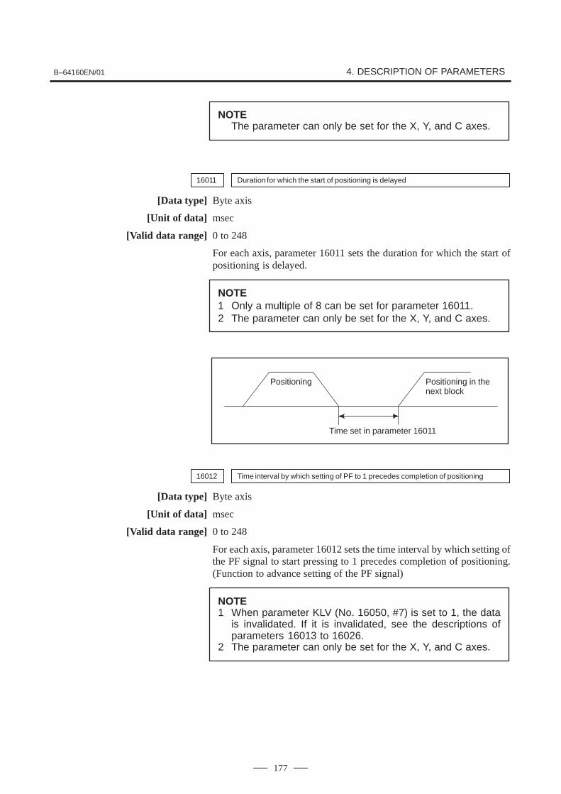
B–64160EN/01 4. DESCRIPTION OF PARAMETERS
177
NOTEThe parameter can only be set for the X, Y, and C axes.
16011 Duration for which the start of positioning is delayed
[Data type] Byte axis
[Unit of data] msec
[Valid data range] 0 to 248
For each axis, parameter 16011 sets the duration for which the start ofpositioning is delayed.
NOTE1 Only a multiple of 8 can be set for parameter 16011.2 The parameter can only be set for the X, Y, and C axes.
Positioning
Time set in parameter 16011
Positioning in thenext block
16012 Time interval by which setting of PF to 1 precedes completion of positioning
[Data type] Byte axis
[Unit of data] msec
[Valid data range] 0 to 248
For each axis, parameter 16012 sets the time interval by which setting ofthe PF signal to start pressing to 1 precedes completion of positioning.(Function to advance setting of the PF signal)
NOTE1 When parameter KLV (No. 16050, #7) is set to 1, the data
is invalidated. If it is invalidated, see the descriptions ofparameters 16013 to 16026.
2 The parameter can only be set for the X, Y, and C axes.

4. DESCRIPTION OF PARAMETERS B–64160EN/01
178
Time interval by which setting of PF to 1 precedes completion of X–axis position-ing for the distance of level 1
16013
Time interval by which setting of PF to 1 precedes completion of X–axis position-ing for the distance of level 2
16014
Time interval by which setting of PF to 1 precedes completion of X–axis position-ing for the distance of level 3
16015
Time interval by which setting of PF to 1 precedes completion of X–axis position-ing for the distance of level 4
16016
Time interval by which setting of PF to 1 precedes completion of X–axis position-ing for the distance of level 5
16017
Time interval by which setting of PF to 1 precedes completion of X–axis position-ing for the distance of level 6
16018
Time interval by which setting of PF to 1 precedes completion of X–axis position-ing for the distance of level 7
16019
[Data type] Byte
[Unit of data] msec
[Valid data range] 0 to �120
Each of these parameters set the time interval by which setting of the PFsignal to start pressing to 1 precedes completion of X–axis positioning forthe corresponding distance level. (Function to advance setting of PFsignal)
The parameters are validated when parameter KLV (No. 16050, #7) is setto 1.
For the positioning distance, see the descriptions of parameters 16055 to16066.
NOTEIf a negative value is specified, the PF signal is set to 1 whenthe corresponding time period elapses after the completionof the positioning.

B–64160EN/01 4. DESCRIPTION OF PARAMETERS
179
Time interval by which setting of PF to 1 precedes completion of Y–axis position-ing for the distance of level 1.
16020
Time interval by which setting of PF to 1 precedes completion of Y–axis position-ing for the distance of level 2.
16021
Time interval by which setting of PF to 1 precedes completion of Y–axis position-ing for the distance of level 3.
16022
Time interval by which setting of PF to 1 precedes completion of Y–axis position-ing for the distance of level 4.
16023
Time interval by which setting of PF to 1 precedes completion of Y–axis position-ing for the distance of level 5.
16024
Time interval by which setting of PF to 1 precedes completion of Y–axis position-ing for the distance of level 6.
16025
Time interval by which setting of PF to 1 precedes completion of Y–axis position-ing for the distance of level 7.
16026
[Data type] Byte
[Unit of data] msec
[Valid data range] 0 to �120
Each of these parameters set the time interval by which setting of the PFsignal to start pressing to 1 precedes completion of Y–axis positioning forthe corresponding distance level. (Function to advance setting of PFsignal)
The parameters are validated when parameter KLV (No. 16050, #7) is setto 1.
For the positioning distance, set the descriptions of data 16055 to 16066.
NOTEIf a negative value is specified, the PF signal is set to 1 whenthe corresponding time period elapses after the completionof the positioning.
Time interval by which setting of PF to 1 precedes completion of C–axis position-ing for the distance of level 1.
16027
Time interval by which setting of PF to 2 precedes completion of C–axis position-ing for the distance of level 2.
16028
Time interval by which setting of PF to 3 precedes completion of C–axis position-ing for the distance of level 3.
16029
[Data type] Byte
[Unit of data] msec
[Valid data range] 0 to �120
Each of these parameters set the time intarval by which setting of the PFsignal to start pressing to 1 precedes completion of C–axis positioning forthe corresponding distance level. (Function to advance setting of PFsignal)

4. DESCRIPTION OF PARAMETERS B–64160EN/01
180
The parameters are validated when parameter KLC (No. 16050, #4) is setto 1.
For the positioning distance, see the description of data 16140 and 16141.
NOTEIf a negative value is specified, the PF signal is set to 1 whenthe corresponding time period elapses after the completionof the positioning.
Positioning
Time set in the parameter
PF
(Function to advance setting of PF signal)
If the time set here is longer than the time required for deceleration, thePF signal is set to1 when decelaration starts.
In simultaneous positioning for the X, Y, and C axes, the PF signal is setto 1 when the individual conditions for the X, Y, and C axes are allsatisfied.
C–axispositioning
Time set for the C–axis
X–axispositioning
Y–axispositioning
Time set for the Y–axis
Time set for the X–axis
PF

B–64160EN/01 4. DESCRIPTION OF PARAMETERS
181
Time interval by which setting PF to 0 follows setting *PE to 0 in single–cyclepressing
16030
[Data type] Byte
[Unit of data] msec
[Valid data range] 0 to 248
Parameter 16030 sets the time interval by which setting the PF signal tostart pressing to 0 follows setting the contact of the *PE signal to stoppressing to 0 in single–cycle pressing.
Time interval between completion of positioning and the start of the next blockwhen PFL is set to 1
16031
[Data type] Byte
[Unit of data] msec
[Valid data range] 0 to 248
Parameter 16031 sets the time interval between completion of positioningand the start of the next block when are PFL signal to lock the start ofpressing is set to 1.
16032 Time interval by which setting of PF to 1 follows positioning in the forming mode
[Data type] Byte
[Unit of data] msec
[Valid data range] 0 to 248
Parameter 16032 sets the time interval by which setting the PF signal tostart pressing to 1 follows positioning in the forming mode (except fornibbling).
Time interval by which the start of the next bolck follows setting of *PFIN to 0 inthe forming mode
16033
[Data type] Byte
[Unit of data] msec
[Valid data range] 0 to 248
Parameter 16033 sets the time interval by which the start of the next blockfollows setting the contact of the *PFIN signal to complete punching forsingle–cycle pressing to 0 in the forming mode.
Positioning
Time set in parameter 16032
Next block
Time set in parameter 16033
PF
*PFIN

4. DESCRIPTION OF PARAMETERS B–64160EN/01
182
16034 Time interval by which setting PF to 1 follows first positioning in nibbling
[Data type] Byte
[Unit of data] msec
[Valid data range] 0 to 248
Parameter 16034 sets the time interval by which setting the PF signal tostart pressing to 1 follows positioning at the first punch point in nibbling(nibbling by G68, G69, and M code).
Time interval by which the start of the next block follows setting *NFIN to 0 at thelast positioning in nibbling
16035
[Data type] Byte
[Unit of data] msec
[Valid data range] 0 to 248
Parameter 16035 sets the time interval by which the start of the next blockfollows setting the contact of the *NFIN signal to complete punching forcontinuous pressing to 0 at positioning at the last punch point in nibbling(nibbling by G68, G69, and M code).
Minimum time interval by which setting of PF to 1 follows setting of *PFIN to 0 insingle–cycle pressing
16036
[Data type] Byte
[Unit of data] msec
[Valid data range] 0 to 248
Parameter 16036 sets the minimum time interval by which setting the PFsignal to start pressingto 1 follows setting the contact of the *PFIN signalto complete punching for single–cycle pressing to 0 in single–cyclepressing. After the contact of *PFIN is set to 0, PF is set to 1 when the timeset here elapses. PF is not set to 1 even if positioning for the next blockcompletes and other conditions are satisfied before the time elapses.
Time interval by which setting PFB to 1 follows setting PF to 1 and settiug PF to0 follows setting PFB to 0
16037
[Data type] Byte
[Unit of data] msec
[Valid data range] 0 to 20
Parameter 16037 sets the time interval by which setting the PFB signalto start pressing B to 1follows setting the PF signal to start pressing to 1and setting PF to 0 follows setting PFB to 0.
NOTE1 Only a multiple of 2 can be set for parameter 16037.2 The parameter must be set to 0 when the PFB signal is not
used.

B–64160EN/01 4. DESCRIPTION OF PARAMETERS
183
PF
PFB
*PE
Time set in parameter 16037
Time set in parameter 16030
Time set in parameter 16037
16038 Time interval by which setting PF to 0 follows setting PFB to 0
[Data type] Byte
[Unit of data] msec
[Valid data range] 0 to 20
Parameter 16038 sets the time interval by which setting the PF signal tostart pressing to 0 follows setting the PFB signal to start pressing B to 0.
The data is validated when parameter PF9 (No. 16002, #6) is set to 1.
NOTEOnly a multiple of 2 can be set in parameter 16038.
PF
PFB
*PE
Time set in parameter 16037
Time set in parameter 16030
Time set in parameter 16038
16039 Time interval by which setting PF to 0 follows setting *PE to 0 in nibbling
[Data type] Byte
[Unit of data] msec
[Valid data range] 0 to 248
Parameter 16039 sets the time interval by which setting the PF signal tostart pressing to 0 follows setting the contact of the *PE signal to stoppressing to 0 in nibbing.
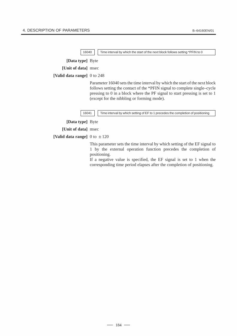
4. DESCRIPTION OF PARAMETERS B–64160EN/01
184
16040 Time interval by which the start of the next block follows setting *PFIN to 0
[Data type] Byte
[Unit of data] msec
[Valid data range] 0 to 248
Parameter 16040 sets the time interval by which the start of the next blockfollows setting the contact of the *PFIN signal to complete single–cyclepressing to 0 in a block where the PF signal to start pressing is set to 1(except for the nibbling or forming mode).
16041 Time interval by which setting of EF to 1 precedes the completion of positioning
[Data type] Byte
[Unit of data] msec
[Valid data range] 0 to �120
This parameter sets the time interval by which setting of the EF signal to1 by the external operation function precedes the completion ofpositioning.If a negative value is specified, the EF signal is set to 1 when thecorresponding time period elapses after the completion of positioning.

B–64160EN/01 4. DESCRIPTION OF PARAMETERS
185
#7 #6 #5 #4 #3 #2 #1 #0
16050 KLV PCT CT2 KLC NCT PCF G0F
[Data type] Bit
G0F For a rapid traverse command (G00), the X–axis or Y–axis rapid traversefeedrate is set to the value:0: Specified in the parameter.1: Specified by the F code.
The maximum feedrate of the F command is limited to the rapid traversefeedrate in the parameter. KLV (No. 16050, #7) and LPG (No. 16051, #4)are valid.
PCF The X–axis or Y–axis movement mode is selected for the followingblocks:(1) Movement to each punch point with the pattern function (G26, G76,
G77, G78, etc.)(2) Operation in automatic repositioning (G75)(3) Movement to the first punch point with the nibbling function (G68,
G69, and M code)0: Rapid traverse is executed.1: For G00, rapid traverse is executed. For G01, G02, or G03, linear
interpolation cutting feed is executed.
NCT Constant control of positioning time is:0: Always enabled.1: Enabled only when the nibbling command is executed.
This parameter is valid when the PCT bit (bit 6 of parameter 16050) is setto 1.
KLC When rapid traverse is executed in automatic operation, the function tochange the time constant and C–axis rapid traverse feedrate among threelevels according to the positioning angleis:0: Invalidated.1: Validated. See the descriptions of parameters 16140 to 16147.
CT2 In constant control of the positioning time, the times specified inparameters 16095 to 16102 are:0: Not changed.1: Doubled.
PCT Constant control of positioning time is:0: Invalidated.1: Validated.
The parameter is validated when parameter KLV (No. 16050, #7) is setto 1.See the descriptions of parameters 16095 to 16102.
KLV When rapid traverse is executed in automatic operation, the function tochange the time constant and X–axis and Y–axis rapid traverse feedratesamong seven levels according to the positioning distance is:0: Invalidated.1: Validated. See the descriptions of data 16055 to 16094.
4.38PARAMETERS FORTHE SPEED ANDLOOP GAIN SWITCH

4. DESCRIPTION OF PARAMETERS B–64160EN/01
186
#7 #6 #5 #4 #3 #2 #1 #0
16051 PGC LPG KLT
[Data type] Bit
KLT When rapid traverse is executed in automatic operation, the function tochange the servo loop gain of position control and time constant of T–axisrapid traverse among three levels according to the indexed angle is:0: Invalidated.1: Validated.
See the descriptions of parameters 16117 to 16124.
LPG When rapid traverse is executed in automatic operation, the function tochange the servo loop gain of X–axis and Y–axis position control amongseven levels according to the positioning distance is:0: Invalidated.1: Validated.
The parameter is validated when parameter KLV (No. 16050, #7) is setto 1.See the descriptions of parameters 16103 to 16116.
PGC Servo loop gains of X–axis and Y–axis position control to be used in rapidtraverse and cutting feed:0: Are the same.1: Can be set separately. See the description of parameter 16160.
#7 #6 #5 #4 #3 #2 #1 #0
16052 TJG TCO NJC
[Data type] Bit
NJC The jog feedrate is:0: Limited to the manual rapid traverse rate.1: Not limited to the manual rapid traverse rate.
TCO For the T or C axis, a rapid traverse override is:0: Validated.
ROV1 ROV2 T–axis or C–axis override
0 0 100%
1 0 100%
0 1 50%
1 1 50%
1: Invalidated. (The rapid traverse override is always 100%.)
TJG The jog override signals for the T–axis and C–axis (G233, #0 and #1) are:0: Not used.1: Used.
*JVT1 *JVT2 T–axis or C–axis override
1 1 25%
1 0 50%
0 1 75%
0 0 100%

B–64160EN/01 4. DESCRIPTION OF PARAMETERS
187
#7 #6 #5 #4 #3 #2 #1 #0
16053 ROM TMO
[Data type] Bit
TMO Override for a linear acceleration/deceleration time constant for rapidtraverse is:0: Disabled1: Enabled
ROM Rapid traverse override is carried out:0: According to the conventional specification.1: According to the specification for the 16i/18i–M.
The PF signal is issued in advance only when the override is 100%.The constant positioning–time control function cannot be used.
#7 #6 #5 #4 #3 #2 #1 #0
16054 NAZj
[Data type] Bit axis
NAZj Specifies whether to make a return to the reference position of the CNCcontrolled axis using G28 as follows:0: Make a return.1: Do not make a return.
16055 Distance D1 to level 1 (in mm)
16056 Distance D2 to level 2 (in mm)
16057 Distance D3 to level 3 (in mm)
16058 Distance D4 to level 4 (in mm)
16059 Distance D5 to level 5 (in mm)
16060 Distance D6 to level 6 (in mm)
16061 Distance D1 to level 1 (in inches)
16062 Distance D2 to level 2 (in inches)
16063 Distance D3 to level 3 (in inches)
16064 Distance D4 to level 4 (in inches)
16065 Distance D5 to level 5 (in inches)
16066 Distance D6 to level 6 (in inches)
[Data type] Two–word
[Unit of data]
Increment system IS–A IS–B Units
Input in milimeters 0.01 0.001 mm
Input in inches 0.001 0.0001 inch
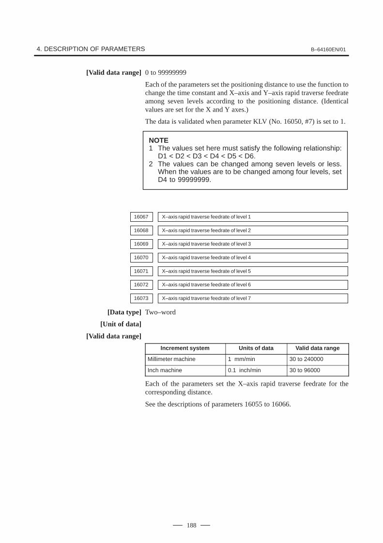
4. DESCRIPTION OF PARAMETERS B–64160EN/01
188
[Valid data range] 0 to 99999999
Each of the parameters set the positioning distance to use the function tochange the time constant and X–axis and Y–axis rapid traverse feedrateamong seven levels according to the positioning distance. (Identicalvalues are set for the X and Y axes.)
The data is validated when parameter KLV (No. 16050, #7) is set to 1.
NOTE1 The values set here must satisfy the following relationship:
D1 < D2 < D3 < D4 < D5 < D6.2 The values can be changed among seven levels or less.
When the values are to be changed among four levels, setD4 to 99999999.
16067 X–axis rapid traverse feedrate of level 1
16068 X–axis rapid traverse feedrate of level 2
16069 X–axis rapid traverse feedrate of level 3
16070 X–axis rapid traverse feedrate of level 4
16071 X–axis rapid traverse feedrate of level 5
16072 X–axis rapid traverse feedrate of level 6
16073 X–axis rapid traverse feedrate of level 7
[Data type] Two–word
[Unit of data]
[Valid data range]
Increment system Units of data Valid data range
Millimeter machine 1 mm/min 30 to 240000
Inch machine 0.1 inch/min 30 to 96000
Each of the parameters set the X–axis rapid traverse feedrate for thecorresponding distance.
See the descriptions of parameters 16055 to 16066.
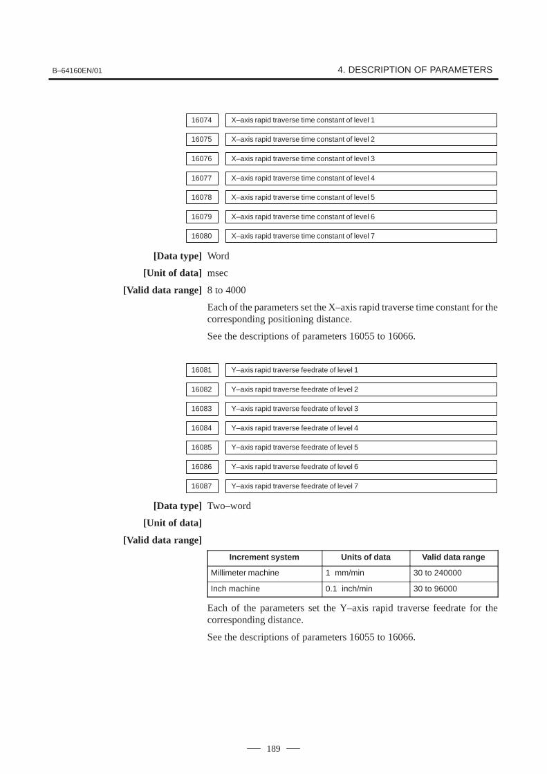
B–64160EN/01 4. DESCRIPTION OF PARAMETERS
189
16074 X–axis rapid traverse time constant of level 1
16075 X–axis rapid traverse time constant of level 2
16076 X–axis rapid traverse time constant of level 3
16077 X–axis rapid traverse time constant of level 4
16078 X–axis rapid traverse time constant of level 5
16079 X–axis rapid traverse time constant of level 6
16080 X–axis rapid traverse time constant of level 7
[Data type] Word
[Unit of data] msec
[Valid data range] 8 to 4000
Each of the parameters set the X–axis rapid traverse time constant for thecorresponding positioning distance.
See the descriptions of parameters 16055 to 16066.
16081 Y–axis rapid traverse feedrate of level 1
16082 Y–axis rapid traverse feedrate of level 2
16083 Y–axis rapid traverse feedrate of level 3
16084 Y–axis rapid traverse feedrate of level 4
16085 Y–axis rapid traverse feedrate of level 5
16086 Y–axis rapid traverse feedrate of level 6
16087 Y–axis rapid traverse feedrate of level 7
[Data type] Two–word
[Unit of data]
[Valid data range]
Increment system Units of data Valid data range
Millimeter machine 1 mm/min 30 to 240000
Inch machine 0.1 inch/min 30 to 96000
Each of the parameters set the Y–axis rapid traverse feedrate for thecorresponding distance.
See the descriptions of parameters 16055 to 16066.

4. DESCRIPTION OF PARAMETERS B–64160EN/01
190
16088 Y–axis rapid traverse time constant of level 1
16089 Y–axis rapid traverse time constant of level 2
16090 Y–axis rapid traverse time constant of level 3
16091 Y–axis rapid traverse time constant of level 4
16092 Y–axis rapid traverse time constant of level 5
16093 Y–axis rapid traverse time constant of level 6
16094 Y–axis rapid traverse time constant of level 7
[Data type] Word
[Unit of data] msec
[Valid data range] 8 to 4000
Each of the parameters set the Y–axis rapid traverse time constant for thecorresponding positioning distance.
See the descriptions of parameters 16055 to 16066.
Relationship between positioning distances and data numbers
LevelPositioning
X–axis Y–axis
LevelPositioning
distanced
Rapidtraversefeedrate
Rapid tra-verse timeconstant
Rapidtraversefeedrate
Rapid tra-verse timeconstant
1 0<d�D1 16067 16074 16081 16088
2 D1<d�D2 16068 16075 16082 16089
3 D2<d�D3 16069 16076 16083 16090
4 D3<d�D4 16070 16077 16084 16091
5 D4<d�D5 16071 16078 16085 16092
6 D5<d�D6 16072 16079 16086 16093
7 D6<d 16073 16080 16087 16094
16095 X–axis positioning time of level 1 (Rapid traverse override of 100% or 75%)
16096 X–axis positioning time of level 1 (Rapid traverse override of 50% or 25%)
16097 X–axis positioning time of level 2 (Rapid traverse override of 100% or 75%)
16098 X–axis positioning time of level 2 (Rapid traverse override of 50% or 25%)

B–64160EN/01 4. DESCRIPTION OF PARAMETERS
191
16099 Y–axis positioning time of level 1 (Rapid traverse override of 100% or 75%)
16100 Y–axis positioning time of level 1 (Rapid traverse override of 50% or 25%)
16101 Y–axis positioning time of level 2 (Rapid traverse override of 100% or 75%)
16102 Y–axis positioning time of level 2 (Rapid traverse override of 50% or 25%)
[Data type] Byte
[Unit of data] msec
[Valid data range] 32 to 248
When constant control of the positioning time is applied, each of theparameters set the X–axisor Y–axis positioning time for the positioningdistance of level one or two.
The parameters are validated when parameter KLV (No. 16050, #7) andPCT (No. 16050, #6) are set to 1.
NOTEWhen this function is used, parameters 16067, 16068,16074, 16075, 16081, 16082, 16088, and 16089 areinvalidated. Constant control of the positioning time isapplied, irrespective of the positioning distance.
16103 X–axis servo loop gain of level 1
16104 X–axis servo loop gain of level 2
16105 X–axis servo loop gain of level 3
16106 X–axis servo loop gain of level 4
16107 X–axis servo loop gain of level 5
16108 X–axis servo loop gain of level 6
16109 X–axis servo loop gain of level 7
[Data type] Word
[Unit of data] 0.01 sec–1
[Valid data range] 1 to 9999
Each of the parameters set the servo loop gain of X–axis position controlfor the corresponding positioning distance.
See the descriptions of parameters 16055 to 16066.

4. DESCRIPTION OF PARAMETERS B–64160EN/01
192
16110 Y–axis servo loop gain of level 1
16111 Y–axis servo loop gain of level 2
16112 Y–axis servo loop gain of level 3
16113 Y–axis servo loop gain of level 4
16114 Y–axis servo loop gain of level 5
16115 Y–axis servo loop gain of level 6
16116 Y–axis servo loop gain of level 7
[Data type] Word
[Unit of data] 0.01 sec–1
[Valid data range] 1 to 9999Each of the parameters set the servo loop gain of Y–axis position controlfor the corresponding positioning distance.
See the descriptions of parameters 16055 to 16066.
16117 T–axis angle to level 1
16118 T–axis angle to level 2
[Data type] Word
[Unit of data] 0.1 deg
[Valid data range] 0 to 3600
Each of the parameters set the indexed angle to use the function forchanging the T–axis rapid traverse time constant and servo loop gain ofposition control among three levels according to the indexed angle.
The parameters are validated when parameter KLT (No. 16051, #3) is setto 1.
NOTEThe value of level 1 must be smaller than the value of level 2.
16119 T–axis rapid traverse time constant of level 1
16120 T–axis rapid traverse time constant of level 2
16121 T–axis rapid traverse time constant of level 3
[Data type] Word
[Unit of data] msec
[Valid data range] 8 to 4000Each of the parameters set the T–axis rapid traverse time constant to usethe function for changing the T–axis rapid traverse time constant andservo loop gain of position control among three levels according to theindexed angle.
See the descriptions of parameters 16117 and 16118.

B–64160EN/01 4. DESCRIPTION OF PARAMETERS
193
16122 T–axis servo loop gain of level 1
16123 T–axis servo loop gain of level 2
16124 T–axis servo loop gain of level 3
[Data type] Word
[Unit of data] 0.01 sec–1
[Valid data range] 1 to 9999
Each of the parameters set the servo loop gain of T–axis position controlto use the function for changing the T–axis rapid traverse time constandand servo loop gain of position control among three levels according tothe indexed angle.
See the descriptions of parameters 16117 and 16118.
16140 C–axis angle to level 1
16141 C–axis angle to level 2
[Data type] Two–word
[Unit of data] 0.01 deg (IS–A)/0.001 deg (IS–B)
[Valid data range] 0 to 99999999
Each of the paramters set the positioning angle to use the function forchanging the C–axis rapid traverse feedrate and time constant amongthree levels according to the positioning angle.
The data is validated when parameter KLC (No. 16050, #4) is set to 1.
NOTEThe value of level 1 must be smaller than the value of level2.
16142 C–axis rapid traverse feedrate of level 1
16143 C–axis rapid traverse feedrate of level 2
16144 C–axis rapid traverse feedrate of level 3
[Data type] Two–word
[Unit of data] 1 deg/min
[Valid data range] 30 to 240000
Each of the parameters set the C–axis rapid traverse feedrate to use thefunction for changing the C–axis rapid traverse feedrate and rapid traversetime constant among tree levels according to the positioning angle.
See the descriptions of parameters 16140 and 16141.

4. DESCRIPTION OF PARAMETERS B–64160EN/01
194
16145 C–axis rapid traverse time constant of level 1
16146 C–axis rapid traverse time constant of level 2
16147 C–axis rapid traverse time constant of level 3
[Data type] Word
[Unit of data] msec
[Valid data range] 8 to 4000
Each of the parameters set the C–axis rapid traverse to use the functionfor changing the C–axis rapid traverse feedrate and rapid traverse timeconstant among three levels according to the positioning angle.
See the descriptions of parameters 16140 and 16141.
16160 Servo loop gain in cutting feed
[Data type] Word axis
[Unit of data] 0.01 sec–1
[Valid data range] 1 to 9999
For each axis, the parameter sets the servo loop gain of position controlin cutting feed.
The parameter is validated when parameter PGC (No. 16051, #7) is setto 1.
NOTEThe parameter can only be set for the X and Y axes.

B–64160EN/01 4. DESCRIPTION OF PARAMETERS
195
#7 #6 #5 #4 #3 #2 #1 #0
16181 NPF NSP NPC NMG
[Data type] Bit
NMG When the M code for canceling the nibbling mode (No. 16184) isspecified, the G code in the 01 group is:0: Not changed.1: Changed to G00 (rapid traverse).
NPC The function to change maximum pitch in the nibbling mode between twolevels is:0: Not used.1: Used.
The function can be executed by the SNP signal for changing nibblingbetween two levels or by the M code (No. 16185).
NSP When the *SP signal to halt automatic operation is set to 0 in nibbling,automatic operation is:0: Decelerated and halted immediately.1: Halted after positioning for a nibbling pitch completes.
NPF In nibbling mode, a press sequence is:0: Executed according to conventional signals, NBL and *NFIN.1: Executed according to signals PF, *PFIN, and *PE.
When this parameter is set to 1, a press sequence is executed in the sameway as a sequence for single–cycle press.
16183 M code for setting the nibbling mode
16184 M code for canceling the nibbling mode
[Data type] Byte
[Valid data range] 1 to 255
Parameter 16183 sets the M code for setting the nibbling mode.
16185 M code for setting the nibbling mode in which nibbling is changed between two levels
[Data type] Byte
[Valid data range] 1 to 255
Parameter 16185 sets the M code for setting the nibbling mode in whichnibbling is changed between two levels.
The data is validated when parameter NPC (No. 16181, #1) is set to 1.
NOTEThe M code in parameter 16184 is used to cancel thenibbling mode if set.
4.39PARAMETERS FORTHE NIBBLINGFUNCTION

4. DESCRIPTION OF PARAMETERS B–64160EN/01
196
16186 Maximum pitch for G68 or G69 (in mm)
16187 Maximum pitch for G68 or G69 (in inches)
[Data type] Two–word
[Unit of data]Increment system IS–A IS–B Units
Input in millmeters 0.01 0.001 mm
Input in inches 0.001 0.0001 inch
[Valid data range] 1 to 99999999
Each of the parameters specifies the maximum pitch that can be specifiedwith G01, G02, or G03 for nibbling by G68 or G69 or by an M code.
16188 Maximum pitch for nibbling by the M code (in mm)
16189 Maximum pitch for nibbling by the M code (in inches)
[Data type] Two–word
[Unit of data]Increment system IS–A IS–B Units
Input in millmeters 0.01 0.001 mm
Input in inches 0.001 0.0001 inch
[Valid data range] 1 to 99999999
Each of the parameters set the maximum pitch for nibbling by the M code(No. 16183).
Maximum pitch of the G01, G02 or G03 command for changing nibbling betweentwo levels (in mm)
16190
Maximum pitch of the G01, G02 or G03 command for changing nibbling betweentwo levels (in inches)
16191
[Data type] Two–word
[Unit of data]
Increment system IS–A IS–B Units
Input in millmeters 0.01 0.001 mm
Input in inches 0.001 0.0001 inch
[Valid data range] 1 to 99999999
When nibbling by the M code (No. 16185) is executed or the SNP signalfor changing nibbling between two levels is set to 1 while the function forchanging nibbling between two levels is used,each of the parameters setthe maximum nibbling pitch for the G01, G02, or G03 command.
The parameters are validated when parameter NPC (No.16181, #1) is setto 1.

B–64160EN/01 4. DESCRIPTION OF PARAMETERS
197
Maximum pitch of G00 command for changing nibbling between two levels (in mm)
16192
Maximum pitch of G00 command for changing nibbling between two levels (in inches)
16193
[Data type] Two–word
[Unit of data]
Increment system IS–A IS–B Units
Input in millmeters 0.01 0.001 mm
Input in inches 0.001 0.0001 inch
[Valid data range] 1 to 99999999
When nibbling by the M code (No. 16185) is executed or the SNP signalfor changing nibbling between two levels is set to 1 while the function forchanging nibbling between two levels is used,each of the parameters setsthe maximum nibbling pitch for the G00 command.
The data is validated when parameter NPC (No.16181, #1) is set to 1.
16194 Maximum distance traveled along C–axis in nibbling
[Data type] Two–word
[Unit of data] 0.01 deg (IS–A)/0.001 deg (IS–B)
[Valid data range] 1 to 99999999
The parameter sets the maximum distance traveled along the C–axis forG68 and the nibbling mode.

4. DESCRIPTION OF PARAMETERS B–64160EN/01
198
#7 #6 #5 #4 #3 #2 #1 #0
16200 UVW ABM MUR
[Data type] Bit
MUR U or V macro numbers are handled:0: According to the standard specifications.1: According to the following specifications.
(1)Changing a macro number
Storage and execution: U01 to U69 and U90 to U99
Storage: U70 to U79
Representation of several macros: U80 to U89
(2)Macro numbers are handled in the same way as when parameter16206 of the G73 or G74 command for taking multiple workpiecesis set to 2.
NOTEParameter 16206 is invalidated.
ABM To store and call a pattern, addresses A and B:0: Are used.1: Are not used. (The A and B axes can be used.)
UVW To execute a macro function, addresses U, V, and W:0: Are used.1: Are not used. (The U, V, and W axes can be used.)
#7 #6 #5 #4 #3 #2 #1 #0
16201 MSA AWP IPA APR MLP MPC LIP
[Data type] Bit
LIP In the block immediately following setting a local coordinate system(G52), an incremental command specifies an incremental value from:0: The origin of the local coordinate system.1: The current tool position.
MPC When the number of machined workpieces is counted inmultiple–workpiece machining:0: The number of actually machined workpieces is counted.1: The number is incremented by one when complete machining or
remainder machining is executed (but not when trial machining isexecuted).
MLP Setting for taking multiple workpieces depends on:0: The set parameter (No.16206).1: A signal (MLP1 or MLP2) input from the PMC machine.
APR Upon reset, the repositioning compensation value is:0: Not cleared.1: Added to the workpiece coordinate system and cleared.
4.40PARAMETERS FORTHE PATTERNFUNCTION

B–64160EN/01 4. DESCRIPTION OF PARAMETERS
199
IPA Although positioning is to be executed in the block immediatelyfollowing execution of the pattern function (including G68 or G69), onlya command for either the X– or Y–axis is specified. Movement to thepattern reference point:0: Is not executed for the axis which is not specified.1: Is executed for the axis which is not specified.
AWP When a workpiece coordinate system is specified, automatic coordinatesystem setting is executed as designed for:0: The FANUC Series 16.
When manual return to the reference position is completed, the originof the coordinate system is shifted by the amount set for the selectedworkpiece coordinate system (G54 to G59).
1: The FANUC Series 0–P.When manual return to the reference position is completed, thecoordinates of the automatic coordinate system setting are shifted bythe amount set for the selected workpiece coordinate system (G54 toG59).
MSA When the MUR bit (bit 5 of parameter 16200) is set to 1, the machiningpattern set for multiple–workpiece machining is:0: Disabled. When this is selected, the value of parameter 16206 is
always assumed to be 2.1: Enabled.
#7 #6 #5 #4 #3 #2 #1 #0
16202 AIP
[Data type] Bit
AIP Specifies the condition for the share–proof command (G86).0: Alarm 4506 is issued when I � 1.5P (l � 1.5wl).
(Conventional specification)1: Alarm 4506 is issued when I � P (l � wl).
#7 #6 #5 #4 #3 #2 #1 #0
16203 ACD PCU
[Data type] Bit
PCU The number of machined workpieces is:0: Counted by an MDI command.1: Not counted by an MDI command.
ACD A program block causing a PS alarm is:0: Not displayed.1: Displayed.
See the description of parameter 16229.

4. DESCRIPTION OF PARAMETERS B–64160EN/01
200
#7 #6 #5 #4 #3 #2 #1 #0
16204 PDG BKR
[Data type] Bit
BKR The first automatic repositioning command (G75) that sets automaticoperation signal OP from 0 to 1 uses:0: The values set in parameters 16209 and 16210 as the clearance and
amount of return for the Y–axis.(The clearance and amount of return are identical values.)
1: The values set in parameters 16209 and 16210 as the clearance for theY–axis, and the values set in parameters 16211 and 16212 as theamount of return.(The clearance and amount of return are different values.)
PDG On the graphic screen, a program being drawn is:0: Not displayed.1: Displayed.This parameter is invalid when the 9–inch CRT is being used.
16206 Machining pattern when multiple workpieces are taken
[Data type] Byte
[Valid data range] 0 to 3
Parameter 16206 sets a machining pattern when multiple workpieces aretaken.0: A program without the G73 or G74 command for machining when
multiple workpieces are taken is used.
NOTEAlarm 4539 is issued if the G73 or G74 command is foundwith this setting.
1: A program containing the G73 or G74 command is used and testmachining is executed.
2: A program containing the G73 or G74 command is used and theremaining processing is executed after test machining.
3: A program containing the G73 or G74 command is used and the entiremachining is executed.
16207 M code for clamping a workpiece
16208 M code for releasing the workpiece
[Data type] Byte
[Valid data range] 1 to 255
Parameter 16207 sets the M code for clamping a workpiece. Parameter16208 sets the M code for releasing the workpiece.
In blocks between the M code for clampling a workpiece and the M codefor releasing the workpiece, the distances traveled along the X–axis andY–axis are not take into account in the workpiece coordinate system. ThePF signal to start pressing is not set to 1.

B–64160EN/01 4. DESCRIPTION OF PARAMETERS
201
16209 Clearance and amount of return for the Y axis in automatic repositioning (in mm)
16210 Clearance and amount of return for the Y axis in automatic repositioning (in inches)
[Data type] Two–word
[Unit of data]
Increment system IS–A IS–B Units
Input in millmeters 0.01 0.001 mm
Input in inches 0.001 0.0001 inch
[Valid data range] 1 to �99999999
Each of the parameters sets the clearance and amount of return for theY–axis in automatic repositioning (G75).
16211 Amount of return for the Y–axis in automatic repositioning (G75, in millimeters)
16212 Amount of return for the Y–axis in automatic repositioning (G75, in inches)
[Data type] Two–word
[Unit of data]
Increment system IS–A IS–B Units
Input in millmeters 0.01 0.001 mm
Input in inches 0.001 0.0001 inch
[Valid data range] 1 to �99999999
These parameters specify the amount of return for the Y–axis in automaticrepositioning (G75).The clearance is specified in conventional parameters 16209 and 16210.These parameters are valid when the BKR bit (bit 2 of parameter 16204)is set to 1.
16228 Number of characters that can be stored for a U or V macro function
[Data type] Byte
[Valid data range]
Setting value Number of macro storage characters
0 3200
1 11008
2 22272
3 27072

4. DESCRIPTION OF PARAMETERS B–64160EN/01
202
16229 Color code setting for alarm block display
[Data type] Byte
[Valid data range]
Setting value Alarm color
1 Red
2 Green
3 Yellow
4 Blue
5 Pink
6 Light blue
7 White
Others Pink
This parameter specifies the color code in which a program block causinga PS alarm is displayed. A block causing an overtravel or servo alarm isnot displayed.

B–64160EN/01 4. DESCRIPTION OF PARAMETERS
203
#7 #6 #5 #4 #3 #2 #1 #0
16260 TLP TNM TCL
[Data type] Bit
TCL The T axis is:0: Not controlled by the CNC machine.1: Controlled the CNC machine.
TNM When machine lock signal MLK and the TNG signal for ignoring a Tcommand are on, whether the number following address T is cataloged asa tool number is:0: Not checked.1: Checked.
NOTEGenerally, the tool number is not checked when the TNGsignal is set to 1.
TLP In positioning by the T–axis command, a shift from the current position toa specified position is executed:0: In the direction in which required rotation angle is smaller.1: Linearly.
NOTEThe parameters are validated when parameter TCL (No.16260 #4) is set to 1.
#7 #6 #5 #4 #3 #2 #1 #0
16262 MBT DTF TNA TND TDP PWT JGT NTD
[Data type] Bit
NTD The tool data input screen is:0: Displayed.1: Not displayed.
JGT On the position display screen in jog mode, a T code (tool number) is:0: Not displayed by a signal input from the PMC.1: Displayed by a signal (addresses G234 to G237) input from the PMC.
PWT When the power is turned on, the T code (tool number) on the positiondisplay screen is:0: Set to 0.1: Represented by signal input from the PMC machine (addresses G234
to G237).
TDP On the position screen, a T code is:0: Not displayed.1: Displayed.
This parameter is valid when the TCL bit (bit 4 of parameter 16260) is setto 1 and when the NDPx bit (bit 0 of parameter 3115) is set to 0.
4.41PARAMETERS FORTHE TURRET AXIS
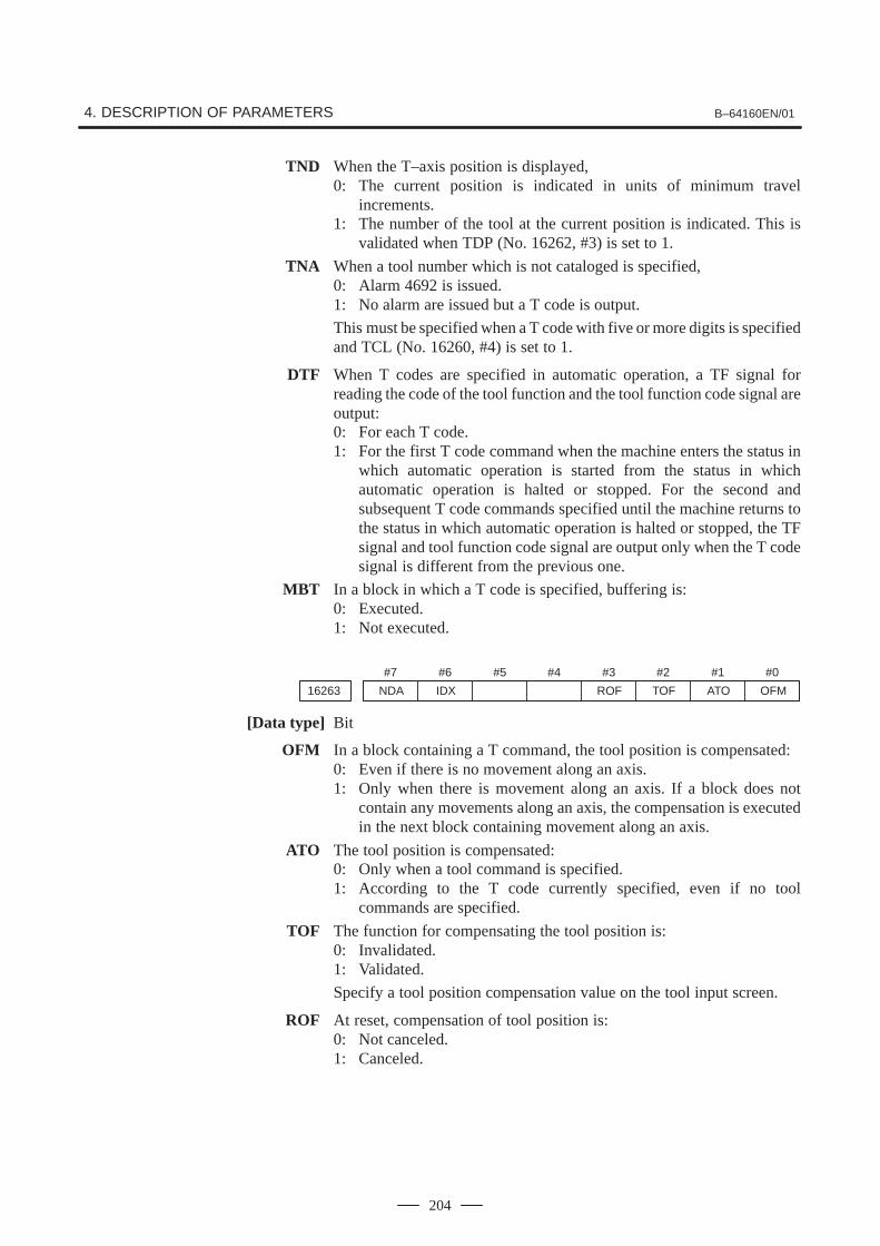
4. DESCRIPTION OF PARAMETERS B–64160EN/01
204
TND When the T–axis position is displayed,0: The current position is indicated in units of minimum travel
increments.1: The number of the tool at the current position is indicated. This is
validated when TDP (No. 16262, #3) is set to 1.
TNA When a tool number which is not cataloged is specified,0: Alarm 4692 is issued.1: No alarm are issued but a T code is output.
This must be specified when a T code with five or more digits is specifiedand TCL (No. 16260, #4) is set to 1.
DTF When T codes are specified in automatic operation, a TF signal forreading the code of the tool function and the tool function code signal areoutput:0: For each T code.1: For the first T code command when the machine enters the status in
which automatic operation is started from the status in whichautomatic operation is halted or stopped. For the second andsubsequent T code commands specified until the machine returns tothe status in which automatic operation is halted or stopped, the TFsignal and tool function code signal are output only when the T codesignal is different from the previous one.
MBT In a block in which a T code is specified, buffering is:0: Executed.1: Not executed.
#7 #6 #5 #4 #3 #2 #1 #0
16263 NDA IDX ROF TOF ATO OFM
[Data type] Bit
OFM In a block containing a T command, the tool position is compensated:0: Even if there is no movement along an axis.1: Only when there is movement along an axis. If a block does not
contain any movements along an axis, the compensation is executedin the next block containing movement along an axis.
ATO The tool position is compensated:0: Only when a tool command is specified.1: According to the T code currently specified, even if no tool
commands are specified.
TOF The function for compensating the tool position is:0: Invalidated.1: Validated.
Specify a tool position compensation value on the tool input screen.
ROF At reset, compensation of tool position is:0: Not canceled.1: Canceled.

B–64160EN/01 4. DESCRIPTION OF PARAMETERS
205
IDX The tool position is not compensated in a block in which no movementalong an axis occurs. In the next block containing movement along an axisthe tool position is compensated:0: For each T code.1: Only for T codes with which turret indexing is not executed.
This is validated when parameter OFM (No. 16263, #0) is set to 1.
NDA If a T command is specified in normal direction mode:0: An alarm is issued (alarm No. 4606).1: An alarm is not issued.
If a multi–tool command is specified, however, an alarm is issued.
16265 Total number of tools to be used
[Data type] Word
[Valid data range] 0 to 136
This parameter specifies the total number of tools to be used by the toolfunction. If T–axis control is selected (TCL bit (bit 4 of parameter 16260)is set to 1), the total number should include the number of tools for whichT–axis control (turret index) is not executed. This parameter can bespecified on the tool input screen. The tool numbers to be used shouldbe specified on the tool input screen.
16266 Number of tools for which T–axis control is executed
[Data type] Word
[Valid data range] 0 to 136
This parameter specifies the number of tools for which T–axis control(turret index) is executed. This parameter is valid when the TCL bit (bit4 of parameter 16260) is set to 1. The parameter can be specified on thetool input screen.
16267 Reference–position tool number under T–axis control
[Data type] Word
[Valid data range] 0 to 9999
This parameter specifies the tool number to be selected upon referenceposition return for the T–axis. This parameter is valid when the TCL bit(bit 4 of parameter 16260) is set to 1. The parameter can be specified onthe tool input screen.

4. DESCRIPTION OF PARAMETERS B–64160EN/01
206
16268 T–axis travel for each rotation of the turret
[Data type] Two-Word
[Unit of data] Least command increment for the T–axis
[Valid data range] 0 to 99999999
This parameter specifies the total T–axis travel for each rotation of theturret. This parameter is valid when the TCL bit (bit 4 of parameter16260) is set to 1. The parameter can be specified using the tool inputscreen. The T–axis machine position (index position) for each tool to beused should be specified using the tool input screen.
16269 Punching count for all tools (low–order)
16270 Punching count for all tools (high–order)
[Data type] Two-Word
[Valid data range] 0 to 99999999
These parameters preset the punching count for all tools to be used.Parameter 16269 can be preset on the tool input screen.

B–64160EN/01 4. DESCRIPTION OF PARAMETERS
207
#7 #6 #5 #4 #3 #2 #1 #0
16360 CBR CIP MAB MAI
[Data type] Bit
MAI The function for compensating the C–axis position is:0: Invalidated.1: Validated.
MAB The function B for compensating the C-axis position is:0: Invalidated.1: Validated.
CIP In G01, G02, and G03 modes, a C–axis command is:0: Disabled1: Enabled
CBR For a tool for which C–axis control can be executed, a C–axis backlashcompensation value is:0: Not separately specified.1: Separately specified.
The tool numbers of those tools for which C–axis control can be executedare specified in parameters 16370 to 16389.
#7 #6 #5 #4 #3 #2 #1 #0
16362 NRC CRM CMO G92 CNT CR0 RCO
[Data type] Bit
RCO At reset, compensation of C–axis position is:0: Not canceled.1: Canceled.
CR0 When reference position return is performed for the C–axis:0: Moves to the zero point of the machine coordinate system.1: Moves to the zero point of the workpiece coordinate system.
CNT If a T code with which turret indexing is not executed is specified when theC axis is not at the reference point, the machine is:0: Moved along the C–axis to the reference point.1: Not moved along the C–axis to the reference point.
This is validated when parameter CRM (No. 16362, #5) is set to 0. TheT code with which turret indexing is not executed must be cataloged.
G92 G92 command for C–axis control is:0: Invalidated.1: Validated.
CMO In positioning for a C–axis command, a shift from the current position to aspecified position is executed:0: In the direction in which the required rotation angle is smaller.1: Linearly.
CRM According to a T command,the machine is:0: Moved along the C–axis to the reference point.1: Not moved along the C–axis to the reference point.
4.42PARAMETERS FORC–AXIS CONTROL

4. DESCRIPTION OF PARAMETERS B–64160EN/01
208
NRC According to the command of automatic return to the reference point(G28), the machine is:0: Moved along the C–axis to the reference point.1: Not moved along the C–axis to the reference point.
This is validated when parameter CRM (No. 16362, #5) is set to 0.
#7 #6 #5 #4 #3 #2 #1 #0
16363 NDC NDB G91
[Data type] Bit
G91 For C–axis control, a G91 command is:0: Disabled1: Enabled
NDB Positioning under normal direction control is carried out:0: According to the conventional specification.1: By handling the C–axis angle immediately before the beginning of
the normal direction control mode, as an offset value.
NDC Positioning under normal direction control is carried out:0: According to the conventional specification.1: By handling the C–axis angle immediately before the beginning of
the normal direction control mode, as the direction normal to the nexttraveling direction.

B–64160EN/01 4. DESCRIPTION OF PARAMETERS
209
16370 Number of tool 1 for which C–axis control can be executed
16371 Number of tool 2 for which C–axis control can be executed
16372 Number of tool 3 for which C–axis control can be executed
16373 Number of tool 4 for which C–axis control can be executed
16374 Number of tool 5 for which C–axis control can be executed
16375 Number of tool 6 for which C–axis control can be executed
16376 Number of tool 7 for which C–axis control can be executed
16377 Number of tool 8 for which C–axis control can be executed
16378 Number of tool 9 for which C–axis control can be executed
16379 Number of tool 10 for which C–axis control can be executed
16380 Number of tool 11 for which C–axis control can be executed
16381 Number of tool 12 for which C–axis control can be executed
16382 Number of tool 13 for which C–axis control can be executed
16383 Number of tool 14 for which C–axis control can be executed
16384 Number of tool 15 for which C–axis control can be executed
16385 Number of tool 16 for which C–axis control can be executed
16386 Number of tool 17 for which C–axis control can be executed
16387 Number of tool 18 for which C–axis control can be executed
16388 Number of tool 19 for which C–axis control can be executed
16389 Number of tool 20 for which C–axis control can be executed
[Data type] Word
[Valid data range] 0 to 9999
Each of the parameters set the number of a tool for which C–axis controlcan be executed.

4. DESCRIPTION OF PARAMETERS B–64160EN/01
210
16390 C-axis backlash 1
16391 C-axis backlash 2
16392 C-axis backlash 3
16393 C-axis backlash 4
16394 C-axis backlash 5
16395 C-axis backlash 6
16396 C-axis backlash 7
16397 C-axis backlash 8
16398 C-axis backlash 9
16399 C-axis backlash 10
16400 C-axis backlash 11
16401 C-axis backlash 12
16402 C-axis backlash 13
16403 C-axis backlash 14
16404 C-axis backlash 15
16405 C-axis backlash 16
16406 C-axis backlash 17
16407 C-axis backlash 18
16408 C-axis backlash 19
16409 C-axis backlash 20
[Data type] Word
[Unit of data] Detection Unit
[Valid data range] –9999 to +9999
Each of these parameters specifies a C–axis backlash for each index(C1–axis backlash under C–axis synchronous control). The parametervalues correspond to the tool numbers specified in parameters 16370 to16389, respectively. The parameters are valid when the CBR bit (bit 7 ofparameter 16360) is set to 1. When these parameters are valid, the C–axisbacklash specified in parameter 1852 is invalid.
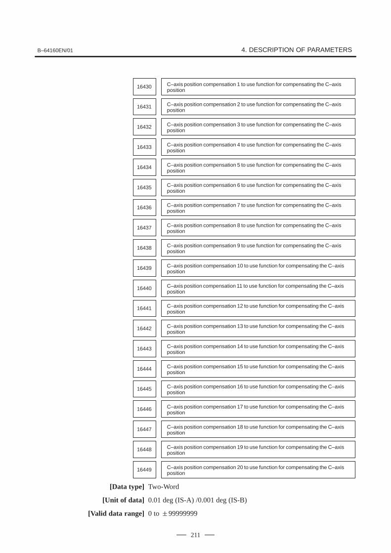
B–64160EN/01 4. DESCRIPTION OF PARAMETERS
211
C–axis position compensation 1 to use function for compensating the C–axisposition
16430
C–axis position compensation 2 to use function for compensating the C–axisposition
16431
C–axis position compensation 3 to use function for compensating the C–axisposition
16432
C–axis position compensation 4 to use function for compensating the C–axisposition
16433
C–axis position compensation 5 to use function for compensating the C–axisposition
16434
C–axis position compensation 6 to use function for compensating the C–axisposition
16435
C–axis position compensation 7 to use function for compensating the C–axisposition
16436
C–axis position compensation 8 to use function for compensating the C–axisposition
16437
C–axis position compensation 9 to use function for compensating the C–axisposition
16438
C–axis position compensation 10 to use function for compensating the C–axisposition
16439
C–axis position compensation 11 to use function for compensating the C–axisposition
16440
C–axis position compensation 12 to use function for compensating the C–axisposition
16441
C–axis position compensation 13 to use function for compensating the C–axisposition
16442
C–axis position compensation 14 to use function for compensating the C–axisposition
16443
C–axis position compensation 15 to use function for compensating the C–axisposition
16444
C–axis position compensation 16 to use function for compensating the C–axisposition
16445
C–axis position compensation 17 to use function for compensating the C–axisposition
16446
C–axis position compensation 18 to use function for compensating the C–axisposition
16447
C–axis position compensation 19 to use function for compensating the C–axisposition
16448
C–axis position compensation 20 to use function for compensating the C–axisposition
16449
[Data type] Two-Word
[Unit of data] 0.01 deg (IS-A) /0.001 deg (IS-B)
[Valid data range] 0 to �99999999

4. DESCRIPTION OF PARAMETERS B–64160EN/01
212
Each of the parameters set the C–axis position compensation to use thefunction for compensating the C–axis position.
These compensated values correspond to the tool numbers set inparameters 16370 to 16389.
The values validated when parameter MAI (No. 16360, #2) is set to 1.

B–64160EN/01 4. DESCRIPTION OF PARAMETERS
213
#7 #6 #5 #4 #3 #2 #1 #0
16500 YSF SAT SF0
[Data type] Bit
SF0 The safety zone of type:0: A is used.1: B is used.
NOTEWhen type B is used, punching is inhibited in punchingmode and entry is inhibited in laser mode.
SAT When punching is inhibited in the safety zone, the block in which a Tcommand is specified is checked:0: In advance.1: After the FIN signal to complete the T command has been received.
YSF When a safety zone check is executed, the inhibited area along the Y axisextends from the values set in parameters 16507, 16510, 16513, and16516:0: In the negative direction.1: In the positive direction.
#7 #6 #5 #4 #3 #2 #1 #0
16501 SZ4 SZ3 SZ2 SZ1
[Data type] Bit
SZj When a safety zone check is executed, in the #j (j=1 to 4) area,0: An entry is inhibited.1: Punching is inhibited.
#7 #6 #5 #4 #3 #2 #1 #0
16502 SOF ACZ ZNO SZ1 GSZ ZIO SZC MDP
[Data type] Bit
MDP On the safety zone setting display,0: The workpiece coordinate system is indicated.1: The machine coordinate system is indicated.
SZC On the safety zone setting display, the data for:0: Any zone can be changed.1: Those zones to be set automatically (parameter 16534) can be
changed.
ZIO When the safety zone is automatically set by an external signal, theposition of a workpiece holder is detected according to:0: The on and off states of the SAFZ signal used to detect the position of
a workpiece holder.1: The on state of the SAFZ signal used to detect the position of a
workpiece holder.
4.43PARAMETERS FORTHE SAFETY ZONE

4. DESCRIPTION OF PARAMETERS B–64160EN/01
214
GSZ On the graphic screen, the safety zone is checked according to the positionof a workpiece holder:0: Specified on the safety zone screen.1: Specified by graphic parameters.
(On the graphic screen, this check is executed in an area that is notrelated to the actual machining check.)
SZI Data set on the safety zone setting display is:0: Invalidated.1: Validated.
ZNO In the safety zone area setting screen of the safety zone B specification, :0: Number of zone and other number than number of zone can be
inputted.1: Number of zone can be inputted.
ACZ The function used to prevent interference between workpiece holders of:0: Type A is used.1: Type B is used.
SOF In the safety zone check, tool position compensation is:0: Not considered.1: Considered.
16505 Positive X coordinate for safety zone 1
16506 Negative X coordinate for safety zone 1
16507 Y coordinate for safety zone 1
16508 Positive X coordinate for safety zone 2
16509 Negative X coordinate for safety zone 2
16510 Y coordinate for safety zone 2
16511 Positive X coordinate for safety zone 3
16512 Negative X coordinate for safety zone 3
16513 Y coordinate for safety zone 3
16514 Positive X coordinate for safety zone 4
16515 Negative X coordinate for safety zone 4
16516 Y coordinate for safety zone 4
[Data type] Two-Word
[Unit of data]
Increment system IS–A IS–B Units
Millimeter machine 0.01 0.001 mm
Inch machine 0.001 0.0001 inch
[Valid data range] 0 to �99999999
Each set of the parameters specify safety zone 1, 2, 3, or 4.

B–64160EN/01 4. DESCRIPTION OF PARAMETERS
215
NOTE1 The values set for zone #n must be smaller than those set
for zone #n + 1. (n: 1 to 3)2 Zeros must be specified for zones which need not be
specified.3 If any of the +X, –X, and Y coordinates are set to 0 for an
area, that area is invalid.
16517 Size of tool area 1 in the X direction for the safety zone function
16518 Size of tool area 1 in the Y direction for the safety zone function
16519 Size of tool area 2 in the X direction for the safety zone function
16520 Size of tool area 2 in the Y direction for the safety zone function
16521 Size of tool area 3 in the X direction for the safety zone function
16227 Size of tool area 3 in the Y direction for the safety zone function
16523 Size of tool area 4 in the X direction for the safety zone function
16524 Size of tool area 4 in the Y direction for the safety zone function
16525 Size of tool area 5 in the X direction for the safety zone function
16526 Size of tool area 5 in the Y direction for the safety zone function
16527 Size of tool area 6 in the X direction for the safety zone function
16528 Size of tool area 6 in the Y direction for the safety zone function
16529 Size of tool area 7 in the X direction for the safety zone function
16530 Size of tool area 7 in the Y direction for the safety zone function
16531 Size of tool area 8 in the X direction for the safety zone function
16532 Size of tool area 8 in the Y direction for the safety zone function
[Data type] Two-Word
[Unit of data]
Increment system IS–A IS–B Units
Millimeter machine 0.01 0.001 mm
Inch machine 0.001 0.0001 inch
[Valid data range] 0 to 99999999
The parameters set 12 tool areas for the safety zone function.
Refer to parameters No. 16551 to No. 16558
NOTEA tool area is selected by signals SZTS0 to SZTS3 inputfrom a PMC machine.

4. DESCRIPTION OF PARAMETERS B–64160EN/01
216
16533 Distance between the position detector of the workpiece holder and the punch
[Data type] Two-Word
[Unit of data]
Increment system IS–A IS–B Units
Millimeter machine 0.01 0.001 mm
Inch machine 0.001 0.0001 inch
[Valid data range] 0 to �99999999
The parameter sets the distance between the position detector of theworkpiece holder and punch.
The sign of the value set in the parameter corresponds to the direction themachine travels along the X–axis, assuming the punch position as zero.
16534 Number of zones to be detected for automatic setting
[Data type] Byte
[Unit of data] Piece
[Valid data range] 0 to 4
This parameter specifies the number of zones to be detected for automaticsetting of a safety zone by an external signal.
NOTEThis parameter must be specified when automatic setting isexecuted.
16535 Retraction position from the X–axis reference position for automatic setting
[Data type] Two-Word
[Unit of data]
Increment system IS–A IS–B Units
Millimeter machine 0.01 0.001 mm
Inch machine 0.001 0.0001 inch
[Valid data range] 0 to �99999999
This parameter specifies a clearance from the X–axis reference positionfor automatic setting of a safety zone by means of an external signal.
NOTESpecify a position that is sufficiently distant to allow thespeed at which the position of a workpiece holder isdetected to become stable.

B–64160EN/01 4. DESCRIPTION OF PARAMETERS
217
16536 X–axis rapid traverse rate for automatic setting
[Data type] Two-Word
[Unit of data]
Increment system Units of data Valid data range
Millimeter machine 1 mm/min 30 to 240000
Inch machine 0.1 inch/min 30 to 9600
This parameter specifies an X–axis rapid traverse rate for automaticsetting of a safety zone by an external signal.
NOTEWhen this parameter is set to 0, the feedrate along theX–axis for automatic detection equals the manual rapidtraverse rate.
16537 X–axis rapid traverse time constant for automatic setting
[Data type] Word
[Unit of data] msec
[Valid data range] 8 to 4000
This parameter specifies an X–axis rapid traverse time constant for theautomatic setting of a safety zone by an external signal.
NOTEWhen this parameter is set to 0, the X–axis time constant forautomatic detection equals the time constant for manualrapid traverse.
16538 Lower limit of position error for movement along the X–axis for automatic setting
16539 Upper limit of position error for movement along the X–axis for automatic setting
[Data type] Two-Word
[Unit of data] Units of detection
[Valid data range] 0 to 99999999
These parameters specify the lower and upper limits, for the position errorfor movement along the X–axis, for the automatic setting of a safety zoneby an external signal. These parameters must be specified for automaticsetting.
NOTEThe values of these parameters must satisfy the followingcondition: Parameter 16538 < Parameter 16539
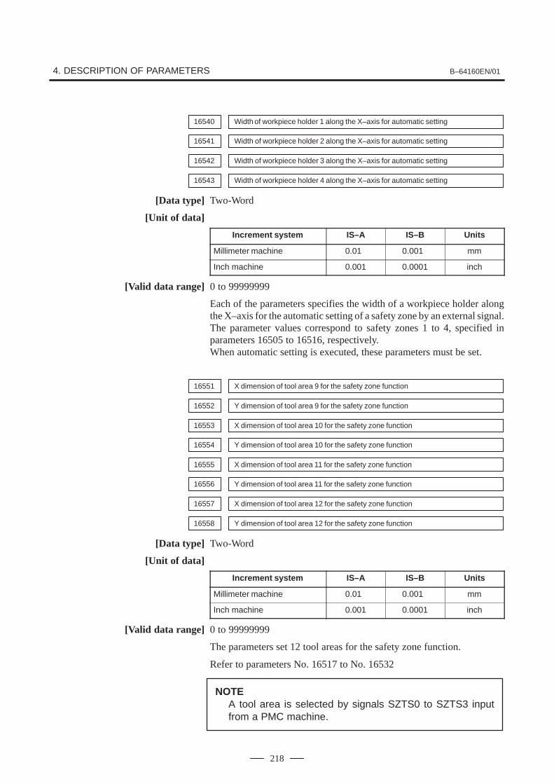
4. DESCRIPTION OF PARAMETERS B–64160EN/01
218
16540 Width of workpiece holder 1 along the X–axis for automatic setting
16541 Width of workpiece holder 2 along the X–axis for automatic setting
16542 Width of workpiece holder 3 along the X–axis for automatic setting
16543 Width of workpiece holder 4 along the X–axis for automatic setting
[Data type] Two-Word
[Unit of data]
Increment system IS–A IS–B Units
Millimeter machine 0.01 0.001 mm
Inch machine 0.001 0.0001 inch
[Valid data range] 0 to 99999999
Each of the parameters specifies the width of a workpiece holder alongthe X–axis for the automatic setting of a safety zone by an external signal.The parameter values correspond to safety zones 1 to 4, specified inparameters 16505 to 16516, respectively.When automatic setting is executed, these parameters must be set.
16551 X dimension of tool area 9 for the safety zone function
16552 Y dimension of tool area 9 for the safety zone function
16553 X dimension of tool area 10 for the safety zone function
16554 Y dimension of tool area 10 for the safety zone function
16555 X dimension of tool area 11 for the safety zone function
16556 Y dimension of tool area 11 for the safety zone function
16557 X dimension of tool area 12 for the safety zone function
16558 Y dimension of tool area 12 for the safety zone function
[Data type] Two-Word
[Unit of data]
Increment system IS–A IS–B Units
Millimeter machine 0.01 0.001 mm
Inch machine 0.001 0.0001 inch
[Valid data range] 0 to 99999999
The parameters set 12 tool areas for the safety zone function.
Refer to parameters No. 16517 to No. 16532
NOTEA tool area is selected by signals SZTS0 to SZTS3 inputfrom a PMC machine.

B–64160EN/01 4. DESCRIPTION OF PARAMETERS
219
16600 Width for the second reference position on each axis
16601 Width for the third reference position on each axis
16602 Width for the fourth reference position on each axis
[Data type] Word
[Unit of data]
Increment system IS–A IS–B Units
Millimeter machine 0.01 0.001 mm
Inch machine 0.001 0.0001 inch
[Valid data range] 0 to 65535
The parameters specify the width for the second, third, or fourth referenceposition of the machine coordinate system. The second, third, or fourthreference position signal is output within the range shown below:
Position specified in parameter 1241, 1242, or 1243
Negative direction Positive direction
Second, third, or fourth reference position signal
Value specified in parame-ter 16600, 16601, of 16602
Value specified in parame-ter 16600, 16601, of 16602
NOTEFor a rotation axis, the specified reference position outputrange must not include 0 of the machine coordinate system.
#7 #6 #5 #4 #3 #2 #1 #0
16747 SUV
[Data type] Bit
This parameter can be changed using the setting screen.
SUV In the reset state, the macros stored under U or V macro numbers are:0: Deleted.1: Not deleted.This parameter is valid when the UVC bit (bit 0 of parameter 16200) isset to 1.
4.44ADDITIONALPARAMETERS FORDI/DO SIGNALS

4. DESCRIPTION OF PARAMETERS B–64160EN/01
220
#7 #6 #5 #4 #3 #2 #1 #0
16748 NUV
[Data type] Bit
NUV Specifies the macro UV storage format.0: Complies with the conventional specification.1: Executes only character storage processing.

APPENDIX

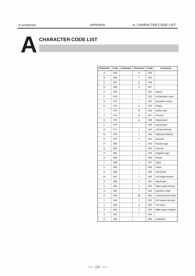
B–64160EN/01 A. CHARACTER CODE LISTAPPENDIX
223
ACHARACTER CODE LIST
Character Code Comment Character Code Comment
A 065 6 054
B 066 7 055
C 067 8 056
D 068 9 057
E 069 032 Space
F 070 ! 033 Exclamation mark
G 071 ” 034 Quotation marks
H 072 # 035 Shape
I 073 $ 036 Dollar mark
J 074 % 037 Percent
K 075 & 038 Ampersand
L 076 ’ 039 Apostrophe
M 077 ( 040 Left parenthesis
N 078 ) 041 Right parenthesis
O 079 * 042 Asterisk
P 080 + 043 Positive sign
Q 081 , 044 Comma
R 082 – 045 Negative sign
S 083 . 046 Period
T 084 / 047 Slash
U 085 : 058 Colon
V 086 ; 059 Semicolon
W 087 < 060 Left angle bracket
X 088 = 061 Equal sign
Y 089 > 062 Right angle bracket
Z 090 ? 063 Question mark
0 048 @ 064 Commercial at mark
1 049 [ 091 Left square bracket
2 050 ¥ 092 Yen mark
3 051 ] 093 Right square bracket
4 052 ^ 094
5 053 095 Underline


IndexB–64160EN/01
i–1
[A]Additional Parameters for DI/DO Signals, 219
[C]Character Code List, 223
[D]Description of Parameters, 7
Displaying Parameters, 1
[I]Inputting and Outputting Parameters Through the
Reader/Puncher Interface, 4
Inputting Parameters through the Reader/Puncher In-terface, 6
[O]Other Parameters, 165
Outputting Parameters through the Reader/PuncherInterface, 5
[P]Parameter of Memory Card Interface, 23
Parameters Common to all Channels, 12
Parameters For C–Axis Control, 207
Parameters for the Nibbling Function, 195
Parameters for the Pattern Function, 198
Parameters for the Safety Zone, 213
Parameters for the Speed and Loop Gain Switch, 185
Parameters for the Turret Axis, 203
Parameters of Acceleration/ Deceleration Control, 49
Parameters of Axis Control by PMC, 150
Parameters of Axis Control/ Increment System, 28
Parameters of Channel 1 (I/O CHANNEL=0), 13
Parameters of Channel 1 (I/O CHANNEL=1), 14
Parameters of Channel 2 (I/O CHANNEL=2), 15
Parameters of Coordinates, 36
Parameters of Custom Macros, 126
Parameters of Data Server, 24
Parameters of DI/DO, 83
Parameters of Display and Edit, 86
Parameters of Displaying Operation Time and Num-ber of Parts, 136
Parameters of DNC2 Interface, 17
Parameters of Ethernet, 26
Parameters of External Data Input/Output, 133
Parameters of Feedrate, 44
Parameters of FSi Basic Functions, 163
Parameters of Graphic Display, 134
Parameters of Maintenance, 169
Parameters of Manual Handle Feed and Handle Inter-ruption, 144
Parameters of Normal Direction Control, 122
Parameters of Operation History, 170
Parameters of Pitch Error Compensation, 110
Parameters of Position Switch Functions, 140
Parameters of Power Mate CNC Manager, 27
Parameters of Programs, 105
Parameters of Reader/Puncher Interface, 11
Parameters of Remote Diagnosis, 20
Parameters of Scaling/Coordinate Rotation, 120
Parameters of Sequence Number Comparison andStop, 162
Parameters of Servo, 62
Parameters of Setting , 8
Parameters of Simple Synchronous Control, 155
Parameters of Skip Function, 131
Parameters of Software Operator’s Panel, 147
Parameters of Stroke Check, 40
Parameters of the Press Function, 174
Parameters of Tool Compensation, 117
[S]Setting Parameters from MDI, 2


Rev
isio
n R
eco
rd
FAN
UC$S
erie
s$0i
– P
C P
AR
AM
ET
ER
MA
NU
AL
(B
–641
60E
N)
01Ju
n., 2
004
Edi
tion
Dat
eC
onte
nts
Edi
tion
Dat
eC
onte
nts


