Jan 2005 Kyung-Kuk Lee (Orthotron Co., Ltd.) Slide 1 doc.: IEEE802.15-05-0025-02-004a Submission Project: IEEE P802.15 Working Group for Wireless Personal Area N Project: IEEE P802.15 Working Group for Wireless Personal Area N etworks etworks (WPANs) (WPANs) Submission Title: [DBO-CSK Proposal for IEEE802.15.4a] Date Submitted: [January 2005] Source: [(1) Kyung-Kuk Lee, (2) J.W.Chong, S.H.Yoon, J.D.Jeong, S.D.Kim, H.U.Lee] Company [(1) Orthotron Co., Ltd. (2) Hanyang University] Address [(1) 709 Kranz Techono, 5442-1 Sangdaewon-dong, Jungwon-gu, Sungnam-si, Kyungki-do, Korea 462-120] Voice:[82-31-777-8198], FAX: [82-31-777-8199], E-Mail:[[email protected]] Re: [Response to Call for Proposal by IEEE802.15.4a] Abstract: [This document has been submitted for an official proposal in January 2005. DBO-CSK Technology is proposed] Purpose: [Proposal for the IEEE802.15.4a standard] Notice: This document has been prepared to assist the IEEE P802.15. It is offered as a basis for discussion and is not binding on the contributing individual(s) or organization(s). The material in this document is subject to change in form and content after further study. The contributor(s) reserve(s) the right to add, amend or withdraw material contained herein. Release: The contributor acknowledges and accepts that this contribution becomes the property of IEEE and may be made publicly available by P802.15.
Transcript
Jan 2005
Kyung-Kuk Lee (Orthotron Co., Ltd.)Slide 1
doc.: IEEE802.15-05-0025-02-004a
Submission
Project: IEEE P802.15 Working Group for Wireless Personal Area NProject: IEEE P802.15 Working Group for Wireless Personal Area Networks etworks (WPANs)(WPANs)
Kyungki-do, Korea 462-120]Voice:[82-31-777-8198], FAX: [82-31-777-8199], E-Mail:[[email protected]]Re: [Response to Call for Proposal by IEEE802.15.4a]
Abstract: [This document has been submitted for an official proposal in January 2005. DBO-CSK Technology is proposed]
Purpose: [Proposal for the IEEE802.15.4a standard]Notice: This document has been prepared to assist the IEEE P802.15. It is offered as a basis for discussion and is not binding on the contributing individual(s) or organization(s). The material in this document is subject to change in form and content after further study. The contributor(s) reserve(s) the right to add, amend or withdraw material contained herein.Release: The contributor acknowledges and accepts that this contribution becomes the property of IEEE and may be made publicly available by P802.15.
1. INTRODUCTION2. M-ary DBO-CSK TECHNOLOGY3. GENERAL SOLUTION CRITERIA
3.1. Unit Manufacturing Cost/Complexity (UMC)3.2. General Definitions3.3. Signal Robustness3.4. Technical Feasibility3.5. Scalability
4. MAC PROTOCOL SUPPLEMENT4.1. MAC Enhancements and Modifications
5. PHY LAYER CRITERIA5.1. Channel models and payload data5.2. Size and Form Factor5.3. PHY-SAP Payload Bit Rate and Data Throughput5.4. Simultaneously Operating Piconets5.5. Signal Acquisition5.6. System Performance5.7. Ranging5.8. Link Budget5.9. Sensitivity5.10. Power Management Modes5.11. Power Consumption5.12. Antenna Practicality
6. Conclusion
Jan 2005
Kyung-Kuk Lee (Orthotron Co., Ltd.)Slide 4
doc.: IEEE802.15-05-0025-02-004a
Submission
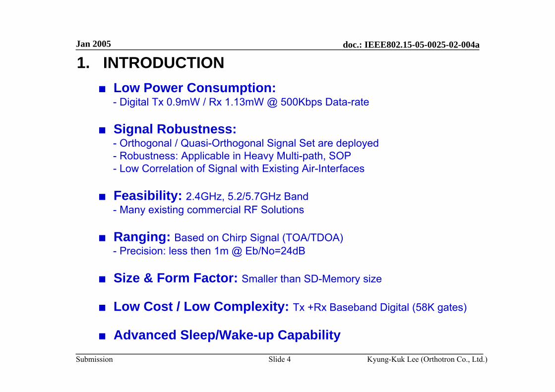
1. INTRODUCTION■ Low Power Consumption:
- Digital Tx 0.9mW / Rx 1.13mW @ 500Kbps Data-rate
■ Signal Robustness:- Orthogonal / Quasi-Orthogonal Signal Set are deployed- Robustness: Applicable in Heavy Multi-path, SOP- Low Correlation of Signal with Existing Air-Interfaces
■ Feasibility: 2.4GHz, 5.2/5.7GHz Band- Many existing commercial RF Solutions
■ Ranging: Based on Chirp Signal (TOA/TDOA)- Precision: less then 1m @ Eb/No=24dB
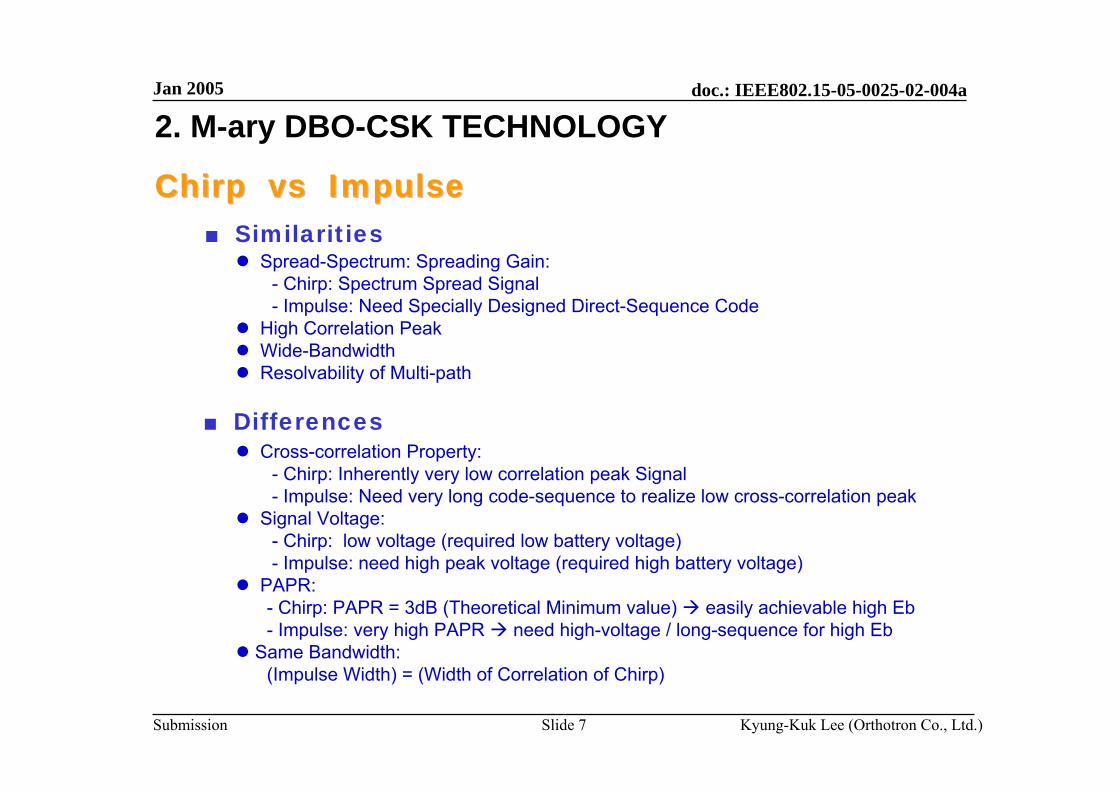
Spread-Spectrum: Spreading Gain:- Chirp: Spectrum Spread Signal- Impulse: Need Specially Designed Direct-Sequence Code
High Correlation PeakWide-BandwidthResolvability of Multi-path
Cross-correlation Property:- Chirp: Inherently very low correlation peak Signal- Impulse: Need very long code-sequence to realize low cross-correlation peak
Signal Voltage:- Chirp: low voltage (required low battery voltage)- Impulse: need high peak voltage (required high battery voltage)
PAPR:- Chirp: PAPR = 3dB (Theoretical Minimum value) easily achievable high Eb- Impulse: very high PAPR need high-voltage / long-sequence for high Eb
Same Bandwidth:(Impulse Width) = (Width of Correlation of Chirp)
Jan 2005
Kyung-Kuk Lee (Orthotron Co., Ltd.)Slide 8
doc.: IEEE802.15-05-0025-02-004a
Submission
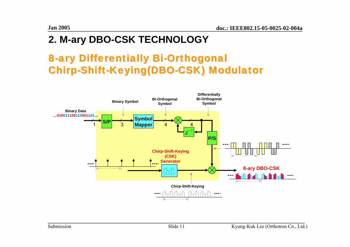
2. M-ary DBO-CSK TECHNOLOGY
Spectrum of SubSpectrum of Sub--Chirp SignalsChirp Signals
Waveform Spectrum
Jan 2005
Kyung-Kuk Lee (Orthotron Co., Ltd.)Slide 9
doc.: IEEE802.15-05-0025-02-004a
Submission
2. M-ary DBO-CSK TECHNOLOGY
ChirpChirp--ShiftShift--Keying (CSK) Signal sets for SOPKeying (CSK) Signal sets for SOPω
ω
ω
ω
I
II
III
IV
Each of CSK Signal consists of 4 sub-chirp signals.
3. GENERAL SOLUTION CRITERIA3.1. Unit Manufacturing Cost/Complexity (UMC)
Jan 2005
Kyung-Kuk Lee (Orthotron Co., Ltd.)Slide 13
doc.: IEEE802.15-05-0025-02-004a
Submission
3. GENERAL SOLUTION CRITERIA3.2. General Definitions
■ Payload bit rate and throughput- 500Kbps throughput: 293Kbps- 250Kbps throughput: 173.7Kbps
■ Error rate: see sub-section 5.6
■ Receiver sensitivity: see sub-section 5.11
■ Antenna gain: 0dBi
■ Band in use: - 2.4GHz ISM Band (10MHz Overlapping)- 5.2/5.7GHz Band (Non-overlapping)- 20MHz Bandwidth: Consists of 4 sub-chirp signals per Carrier
Jan 2005
Kyung-Kuk Lee (Orthotron Co., Ltd.)Slide 14
doc.: IEEE802.15-05-0025-02-004a
Submission
3. GENERAL SOLUTION CRITERIA3.3. Signal Robustness■ Co-existence / Interference Mitigation Technique
- Orthogonal / Quasi-Orthogonal Signal Set - High Spectral Processing Gain: Chirp- Near-Far Problem: FDM Channels (7ch @2.4GHz, 8ch @5.2GHz, 6ch @5.7GHz)
■ Interference Susceptibility- Low Cross-Correlation property with Existing Signal
■ Robustness: - Heavy Multi-path Environment- SOP
■ Low Sensitivity for Component Tolerance- Crystal : ± 40ppm
■ Mobility- Wide-band Chirp: Insensitive for Fading & Doppler Shift- Easily Maintaining Timing Sync. of Received Signal
Jan 2005
Kyung-Kuk Lee (Orthotron Co., Ltd.)Slide 15
doc.: IEEE802.15-05-0025-02-004a
Submission
3. GENERAL SOLUTION CRITERIA3.3. Signal Robustness
■ Ingress- High Processing Gain (10log(20/.5)=16dB- Addition Processing Gain by DS-Spreading (Optional)- Low Cross-Correlation with Existing Air-Interfaces
■ Egress- Same Spectrum Mask with W-LAN @ 2.4GHz, 5.2GHz, 5.7GHz- Tx power control: 10mW / 1mW / 0.1mW (Link Margin)
Jan 2005
Kyung-Kuk Lee (Orthotron Co., Ltd.)Slide 16
doc.: IEEE802.15-05-0025-02-004a
Submission
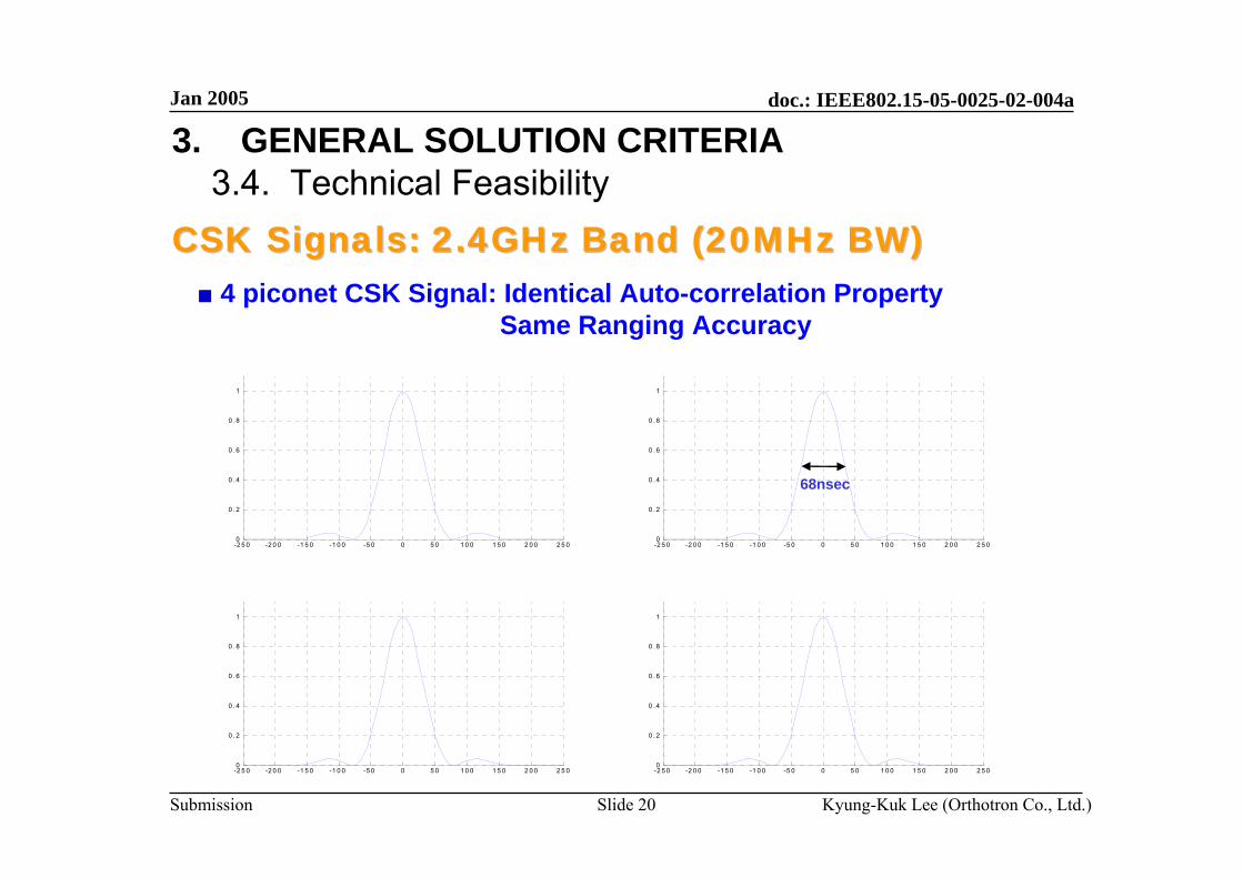
3. GENERAL SOLUTION CRITERIA3.4. Technical Feasibility
D/A
D/A
A/D
A/D
Tx/RxSw.
DBO-CSKMOD
DBO-CSKDEMOD
MACRanging Data
Baseband DigitalRF Analog
A/D , D/A : 3~4 bits
BlockBlock--diagram of DBOdiagram of DBO--CSKCSK TransceiverTransceiver
Jan 2005
Kyung-Kuk Lee (Orthotron Co., Ltd.)Slide 17
doc.: IEEE802.15-05-0025-02-004a
Submission
3. GENERAL SOLUTION CRITERIA3.4. Technical Feasibility■ Manufacturability
- Baseband Digital Chip area: 0.75 / 1.64 mm2 (No FEC / FEC)(0.18um Technology)
- Peak of Differential Detection (Averaging over 4 or more Symbols)
■ Fine Timing Detection- Cross-Correlation of Sampled Input Signal- Fine Timing by Interpolation (Fraction of Sampling-Clock Resolution)- Averaging over 4 or more Symbols- Less than 1m Ranging Resolution @ Eb/No >= 24dB
Arbitrary Sampling Instant
Detected TimingDetected TimingPeak
Edge
Jan 2005
Kyung-Kuk Lee (Orthotron Co., Ltd.)Slide 39
doc.: IEEE802.15-05-0025-02-004a
Submission
1 2 1 4 1 6 1 8 2 0 2 2 2 4 2 6 2 81 0
0
1 0 1
1 0 2
E b /N o (d B )
time
erro
r dev
iatio
n (n
sec)
5. PHY LAYER CRITERIA5.7. Ranging
Timing-error Variance (Chirp BW: 20MHz)
■ TDA / TDOA Based Ranging with Chirp Signal
■ Estimation Precision: < 1m @ Eb/No greater than 24dB
Jan 2005
Kyung-Kuk Lee (Orthotron Co., Ltd.)Slide 40
doc.: IEEE802.15-05-0025-02-004a
Submission
5. PHY LAYER CRITERIA5.8. Link Budget
dBm-94.5 -94.5 -94.5 Proposed Min. Rx Sensitivity Level
dB27.4 28.2 34.8 Link Margin(M=Pr-Pn-S-I)
dB333Implementation Loss(I)
dB12.512.512.5Minimum Eb/No(S)
dBm-110.0 -110.0 -110.0 Average noise power per bit(Pn=N+Nf)
dB777Rx Noise Figure(Nf)
dBm-117.0 -117.0 -117.0 Average noise power per bit
dB47.6 46.8 40.2 Path loss at 1meter(L1=20log10(4pifc'/c))
GHz5.75.20 2.44 fc' = sqrt(fminfmax) -10dB
dBi000Tx antenna gain(Gt)
dBm101010Average Tx Power(Pt)
mW101010Average Tx Power(Pt)
kbps500500500peak payload bit rate(Rb)
UNII(5.7GHz)UNII(5.2GHz)ISM(2.4GHz) Parameter
Jan 2005
Kyung-Kuk Lee (Orthotron Co., Ltd.)Slide 41
doc.: IEEE802.15-05-0025-02-004a
Submission
5. PHY LAYER CRITERIA5.9. Sensitivity
CM5
CM1
CM8
AWGN
-86.5dBm
-87dBm
-85.5dBm
-94.5dBm
Rx Sensitivity level(500kbps)
Bandwidth: 20MHz (2.4GHz Band)
Jan 2005
Kyung-Kuk Lee (Orthotron Co., Ltd.)Slide 42
doc.: IEEE802.15-05-0025-02-004a
Submission
5. PHY LAYER CRITERIA5.10. Power Management Modes
■ Low-power Mode with Advanced Wake-up– The proposed PHY has differentially bi-orthogonal detection
and correlatively independent chirp-pulse waveform for multiple piconet=> Low-power is achieved by advanced wake-up that the only
desired group of nodes are called and the other nodes canestimate wake-up time from sleep state
=> Reducing Duty-Cycle and Extending Battery-life– This is compliant to “power consumption considerations” of
802.15.4 standard, and the mode of operation for advanced wake-up may be added to this standard
Jan 2005
Kyung-Kuk Lee (Orthotron Co., Ltd.)Slide 43
doc.: IEEE802.15-05-0025-02-004a
Submission
5. PHY LAYER CRITERIA5.11. Power Consumption
■ RF: 140mW for Tx (@10mW RF Power), 35mW for Rx
■ Baseband (BB) Digital: 0.9mW for Tx , 1.13mW for Rx
■ RF part consume lot more power than Baseband Digital- Power Reduction of RF ASIC is Essential (C-MOS)
■ Idea for Operating Power Saving:- Use Max. Data-rate mode: shorter time for Tx Data- Sleeping: Longer Time- Save Power: by reducing active time of RF
■ Further Reduction of Power Consumption- Apply 0.13um / 0.09um Technology for ASIC (RF / Baseband)
Jan 2005
Kyung-Kuk Lee (Orthotron Co., Ltd.)Slide 44
doc.: IEEE802.15-05-0025-02-004a
Submission
5. PHY LAYER CRITERIA5.11. Power Consumption
Rx
Tx 141 mW141 mW56KTotal
37.5 mW5.24 mm2152K
36.1 mW4.35 mm2
0.52 mW0.06 mm21.6K0.48 mW0.04 mm21.5KTx
10 mW0.3 mm2-10 mW0.3 mm2-Common
130 mW1.7 mm2-130 mW1.7 mm2-Tx + D/A
5K
49.4K
-
Logic
5 uW
0.42 mW
2.08 mW
25 mW
Power
1.5 mm2145K0.71 mW0.63 mm2Rx
250Kbps (FEC: r=1/2)500Kbps (No FEC)
5 uW
0.42 mW
25 mW
Power
0.08 mm2
1.6 mm2
Die Area
Common
Rx + A/D
Deep Sleep
Baseband@ Sampling-rate:
40MHz
RF@ Tx Power:
10mW
0.08 mm25K
1.6 mm2-
Die AreaLogic
Target Library : 0.18 um Technology
■ Power Consumption for Average Throughput 1 Kbps (w/o FEC)- Average Throughput (500Kbps mode): x Kbps- PTX : 141[mW] / 293 = 481 [uW/sec]- PRX : 36.1[mW] /293 = 123 [uW/sec]
■ Battery: 324[Joule] for Button Cell (10mm D. X 2.5mm H) / 12,000[Joules] for AA Alkaline Cell- (PTX + 50 X PRX)/51 = 130[uW] ----- (Assume TTX : TRX = 1:50 duty-cycle for sensor node)- Battery Life TB = 324/130e-6/3600/24 = 28.8 days Continuously (Button Cell)- Battery Life TB = 12000/130e-6/3600/24/365 = 2.93 years Continuously (AA Alkaline Cell)
Jan 2005
Kyung-Kuk Lee (Orthotron Co., Ltd.)Slide 45
doc.: IEEE802.15-05-0025-02-004a
Submission
5. PHY LAYER CRITERIA5.12. Antenna Practicality
■ Antenna Size- less than SD-Memory size: 24mm X 14mm @2.4GHz
12mm X 9mm @5.2/5.7GHz
■ Frequency / Impulse Response- Almost Flat Freq. Response: Narrow-band
■ Radiation Characteristics- Isotropic: 0dBi
Jan 2005
Kyung-Kuk Lee (Orthotron Co., Ltd.)Slide 46
doc.: IEEE802.15-05-0025-02-004a
Submission
6. Conclusion■ Low Power Consumption: Digital Baseband Tx 0.9mW, Rx 1.13mW
- Power Consumption is heavily depend on RF-chip.
■ Signal Robustness:- Orthogonal / Quasi-Orthogonal Signal Set - Robustness: Tolerance for Heavy Multi-path / SOP, - Low Correlation with Existing Air-Interfaces
■ Feasibility: 2.4GHz ISM Band- Existing commercial RF Solutions- 2.4GHz / 5GHz band is allowed for unlicensed operation- Low Voltage Operation: Low PAPR
■ Ranging: Based on Chirp Signal (TDA / TDOA)- Precision: less then 1m (Standard Deviation) @Eb/N0 = 24dB


![dl.sciencesocieties.org...file:///P|/...20Genome/TPG%20Unassigned/TPG12-09-0025/tpg-2012-09-0025-20130103235410/suppl_data/tpg12-09-0025-supplement6.txt[1/23/2013 3:52:16 PM] GENE_ID](https://static.documents.pub/doc/80x56/5e7b701db542a90c0d69c3fa/dl-filep20genometpg20unassignedtpg12-09-0025tpg-2012-09-0025-20130103235410suppldatatpg12-09-0025-supplement6txt1232013.jpg)


