JANOME DESKTOP ROBOT JR2000N Series Operation Manual Teaching Pendant Operation Thank you for purchasing a Janome Robot. Read this manual thoroughly in order to ensure proper use of this robot. Be sure to read “For Your Safety” before you use the robot. The information will help you protect yourself and others from possible dangers during operation. After having read this manual, keep it in a handy place so that you or the operator can refer to it whenever necessary.
Transcript
JANOME DESKTOP ROBOT JR2000N Series
Operation Manual
Teaching Pendant Operation
Thank you for purchasing a Janome Robot.
Read this manual thoroughly in order to ensure proper use of this robot. Be sure to read “For Your Safety” before you use the robot. The information will help you protect yourself and others from possible dangers during operation.
After having read this manual, keep it in a handy place so that you or the
operator can refer to it whenever necessary.
Teaching Pendant Operation i Desktop Robot JR2000N Series
FOR YOUR SAFETY
Safety Precautions The precautions in this manual are provided for the customer to make the best use of this product safely, and to provide preventive measures against injury to the customer or damage to property.
・・・・・Be sure to follow the instructions・・・・・ Various symbols are used in this manual. Please read the following explanations of each symbol.
● Symbols Indicating the Degree of Damage or Danger The following symbols indicate the degree of damage or danger which may be incurred if the safety notes are ignored.
● Symbols Indicating Details of Danger and Preventive Measures The following symbols indicate the type of safety measure that should be taken:
Indicates a forbidden action.
Do not touch. (Contact prohibition)
Never do this. (General prohibition)
Be sure to unplug power cord from wall outlet.
Do not disassemble, modify, or attempt to repair.
Be sure to follow instructions.
Be sure to check that the machine is grounded.
Indicates a necessary action.
Indicates the safety measures that should be taken.
Be careful. (General caution)
Warning
Caution The Caution symbol indicates the possibility of accidental injury or damage to property.
The Warning symbol indicates the possibility of death or serious injury.
Teaching Pendant Operation ii Desktop Robot JR2000N Series
FOR YOUR SAFETY
Warning Do not use the unit where flammable or corrosive gas is present. Leaked gas accumulated around the unit can cause fire or an explosion.
Use the unit in an environment between 0 and 40 degrees centigrade with a humidity level of 20 to 95 percent and without condensation. Use outside these conditions may result in unit malfunction. IP Protection Rating: IP30 (IP40 for CE specification models)
Use the unit in an environment where no electrical noise is present. Failure to do so may result in unit malfunction or breakdown.
Use the unit in an environment that is not exposed to direct sunlight. Direct sunlight may cause unit malfunction or breakdown.
Install the unit in a place which can endure its weight and conditions while running. Placing the unit in an insufficient or unstable surface may cause the unit to fall, overturn, or break down. This could result in operator injury. Be sure to leave a space of at least 30cm between the back of the robot (equipped with a cooling fan) and the wall. Insufficient space can lead to overheating or fire.
Power the unit only with the rated voltage. Failure to do so may cause electric shock, fire, or unit malfunction.
If the unit is equipped with the I/O-S, install an area sensor or a safety barrier of adequate strength. Otherwise, a person entering anywhere in the robot’s operating range may be injured.
Plug the power cord into the wall outlet firmly. Failure to do so can cause the plug to heat up and may result in fire.
Wipe the power plug with a clean, dry cloth periodically to eliminate dust. Dust accumulation can deteriorate the electrical insulation and cause fire.
Teaching Pendant Operation iii Desktop Robot JR2000N Series
FOR YOUR SAFETY Warning
Be sure to check grounding before you use the unit. Improper grounding can cause electric shock or fire.
Be sure to use the unit within the voltage range indicated. Failure to do so may cause fire or unit malfunction.
Do not allow water or oil to get on the unit and the power cord. Contact with water or oil can cause electric shock, fire, or unit malfunction. IP Protection Rating: IP30 (IP40 for CE specification model)
Be sure to confirm that tools such as the electric screwdriver unit are properly connected. Failure to do so may result in injury or breakdown.
Check the mounting screws regularly so that they are always firmly tightened. Loose screws may cause injury or breakdown.
Be sure to check the wiring to the main unit. Improper wiring may result in unit malfunction or breakdown.
Be sure to secure the movable parts of the unit before transportation. Failure to do so may result in injury or breakdown.
Before operating the unit, be sure to check that there is no danger in or around the operating range. Failure to do so may result in injury.
Teaching Pendant Operation iv Desktop Robot JR2000N Series
Warning
Be sure to unplug the power cord from the power outlet when the unit is not in use for long periods of time. Dust accumulation can cause fire.
Do not attempt to disassemble or modify the unit. Disassembly or modification may cause electric shocks or unit malfunction.
When lubricating or inspecting the unit, unplug the power cord from the power outlet. Failure to do so may result in electric shock or injury.
If anything unusual occurs (e.g. a burning smell or abnormal sound), stop operation and unplug the cable immediately. Contact the dealer from whom you purchased the robot or the office listed on the last page of this manual. Continuous use without repair can cause electric shock, fire, or unit breakdown.
Be sure to turn off the unit before inserting or removing cables such as the teaching pendant cable. Failure to do so may result in electric shock, fire, data loss, or unit malfunction.
Keep the emergency stop switch within reach of an operator while teaching or running the robot. Failure to do so may be dangerous since it may not be possible to stop the robot immediately and safely.
Regularly check that the emergency stop switch works properly. For models with I/O-S circuits, also check that they work properly. Failure to do so may be dangerous since it may not be possible to stop the robot immediately and safely.
FOR YOUR SAFETY
Teaching Pendant Operation v Desktop Robot JR2000N Series
PREFACE The Janome Desktop Robot JR2000N Series is a new low-cost, high-performance robot. We have succeeded in reducing the price while maintaining functionality. Energy- and space-saving qualities have been made possible through the combined use of stepping motors and special micro step driving circuits. This manual describes standard applications of the JR2000N Series. Refer also to the following individual manuals during actual operation of this robot.
Setup Explains how to set up the robot. Be sure to read this manual before you operate the robot.
Maintenance Explains maintenance procedures for the robot.
Basic Instructions Provides part names, data structures, and the basic knowledge necessary to operate the robot. Be sure to read this manual before you operate the robot.
Quick Start Explains the actual operation of the robot with simple running samples. Teaching Pendant Operation Explains how to operate the robot via the teaching pendant.
PC Operation Explains how to operate the robot from a computer (using theJR C-Points software.)
Features I Explains point teaching. Features II Explains commands, variables, and functions. Features III Explains features such as run mode parameters, sequencer programs, etc.Features IV Explains features in the Customizing mode. External Control I (I/O-SYS) Explains the I/O-SYS control.
External Control II (COM Communication)
Explains the COM communication control system (COM1 – COM3).
Specifications Provides comprehensive specifications, including mechanical or electrical requirements.
Please be sure to follow the instructions described in these manuals. Proper use of the robot will ensure continued functionality and high performance.
BE SURE TO PROPERLY GROUND THE ROBOT WHEN INSTALLING.
Be sure to save data whenever it is added or modified. Otherwise, changes will not be saved if the power to the robot is cut off.
Teaching Pendant Operation vi Desktop Robot JR2000N Series
CONTENTS
TEACHING PENDANT OPERATION FOR YOUR SAFETY ______________________________________________________________ i PREFACE_______________________________________________________________________v CONTENTS ____________________________________________________________________ vi TEACHING PENDANT____________________________________________________________ 1
PART NAMES _______________________________________________________________ 1 Teaching Pendant Operation Panel Keys __________________________________________ 2
Base Screen ________________________________________________________________ 4 Run Mode ________________________________________________________________ 4 Administration Mode ________________________________________________________ 5 Customizing Mode__________________________________________________________ 6 Teaching Mode ____________________________________________________________ 7
Selection __________________________________________________________________ 10 Entering Numbers ___________________________________________________________ 12 Entering Characters and Formulas ______________________________________________ 14 Entering Position ____________________________________________________________ 17
Manual Job ______________________________________________________________ 18 How to Copy the Point Coordinates____________________________________________ 19 JOG Mode _______________________________________________________________ 20 MDI Mode _______________________________________________________________ 23
Brightness Adjustment________________________________________________________ 26 Unit of Measure_____________________________________________________________ 27 Display Language ___________________________________________________________ 27 GO Function _______________________________________________________________ 27 JOG Function ______________________________________________________________ 29 Tool for Teaching ____________________________________________________________ 29
Teaching Pendant Operation vii Desktop Robot JR2000N Series
Manual Job Number Setting ___________________________________________________ 30 Save on Changing Mode______________________________________________________ 32 Key Click __________________________________________________________________ 32 Back Light on Teaching ______________________________________________________ 33 Coordinates Display _________________________________________________________ 33
PROGRAM____________________________________________________________________ 34 PROGRAM (POINT DATA) _______________________________________________________ 36
Entering Point Data __________________________________________________________ 36 How to Modify the Point Data __________________________________________________ 37
Coordinates (Position) ______________________________________________________ 38 Point Type _______________________________________________________________ 38 Line Speed_______________________________________________________________ 38 Point Job Number/Additional Function Number___________________________________ 38
Transform into Relative _______________________________________________________ 40 How to Insert a Point _________________________________________________________ 41 How to Delete a Point ________________________________________________________ 41 Block Editing _______________________________________________________________ 42
Block Setting Same Value _____________________________________________________ 48 Reset Line Speed _________________________________________________________ 49 Reset Line Speed Rate _____________________________________________________ 49 Reset Additional Function Data Number ________________________________________ 50
POINT RUN ___________________________________________________________________ 51 PROGRAM (PROGRAM DATA)____________________________________________________ 53
Name Editing_______________________________________________________________ 53 Work Home ________________________________________________________________ 54 Job on Start of Cycle _________________________________________________________ 55 Cycle Mode ________________________________________________________________ 55 PTP Condition ______________________________________________________________ 55 CP Condition _______________________________________________________________ 56 Tool Data __________________________________________________________________ 56
Teaching Pendant Operation viii Desktop Robot JR2000N Series
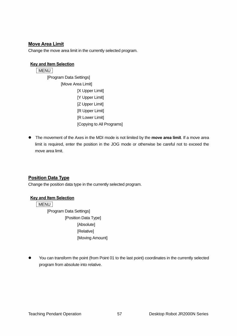
Move Area Limit_____________________________________________________________ 57 Position Data Type __________________________________________________________ 57 Workpiece Weight ___________________________________________________________ 58
POINT JOB DATA ______________________________________________________________ 59
Command Entry ____________________________________________________________ 61 Command Change __________________________________________________________ 63 Command Insertion__________________________________________________________ 63 Command Delete ___________________________________________________________ 63 Block (Command) Delete _____________________________________________________ 64 Block (Command) Move ______________________________________________________ 64 Block (Command) Copy ______________________________________________________ 65 Point Job Name Editing_______________________________________________________ 65 Import Merge_______________________________________________________________ 66 How to Display the Designated Number __________________________________________ 66
SEQUENCER PROGRAM DATA___________________________________________________ 67 ADDITIONAL FUNCTION DATA ___________________________________________________ 69 TEACHING DATA COPY, DELETE, CONVERSION ____________________________________ 71
Program List _______________________________________________________________ 71 Copy _____________________________________________________________________ 72 Delete ____________________________________________________________________ 74 Change Program Number _____________________________________________________ 75 Delete All __________________________________________________________________ 76 Delete All Teaching Data ______________________________________________________ 77 Reset Run Mode Parameter ___________________________________________________ 78 2-Points Position Conversion (Move, Rotate) ______________________________________ 79
Checking Data______________________________________________________________ 81 Error in Point Type _________________________________________________________ 82
Test Run __________________________________________________________________ 84 Error in Point Position ______________________________________________________ 85
IO Test____________________________________________________________________ 85 Test Run (Check IO) _________________________________________________________ 86
SAVING THE C & T DATA ________________________________________________________ 87
Teaching Pendant Operation 1 Desktop Robot JR2000N Series
TEACHING PENDANT PART NAMES
If your teaching pendant is equipped with the enable switch (optional), you need to press the enable switch and the teaching pendant keys at the same time when operating the robot in the Teaching Mode.
Be sure to turn off the robot before removing or inserting the teaching pendant cable. If your teaching pendant has options, be sure to change the model settings accordingly. Failure to do so may cause unit malfunction.
LCD
Enable Switch (Optional)
Operation Panel
Emergency Stop Switch (Optional)
Teaching Pendant Operation 2 Desktop Robot JR2000N Series
Teaching Pendant Operation Panel Keys
F.0 ____ Function 0 Key F.1 ____ Function 1 Key F.2 ____ Function 2 Key F.3 ____ Function 3 Key F.4 ____ Function 4 Key
X ____ X Plus Key X ____ X Minus Key Y ____ Y Minus Key Y ____ Y Plus Key Z ____ Z Up Key Z ____ Z Down Key R ____ R Plus Key R ____ R Minus Key
JOG
Key
MODE ____ Mode Key SAVE ____ Save Key GO ____ Go Key PROG.NO __..Program No. Key J.ENTR ___ .J. Enter Key T.ENV ____ T. ENV key * EDIT ____ Edit Key
CURSOR __. Cursor Left Key CURSOR __. Cursor Right Key CURSOR __. Cursor Up Key CURSOR __. Cursor Down Key
0 – 9 ____ Numeric Key ± ___ Plus Minus Key . ____ .Decimal Point Key
N
umerical Key
JOG SPEED __. JOG Speed Key MONITOR __. Monitor Key MENU _____ Menu Key ESC _____ . Escape Key DEL _______ .. Delete Key CLEAR _____ Clear Key ENTR ______ Enter Key
*: Teaching Environment
Teaching Pendant Operation 3 Desktop Robot JR2000N Series
CHANGING MODE This robot has the following operation modes:
• External Run Mode --------To run programs
(Start running programs using a signal from I/O-SYS or COM1.) • Run Mode --------------------To run programs
(Start running programs by pressing the start switch.) • Teaching Mode -------------To create programs • Customizing Mode ---------To create data to compose programs • Administration Mode ------ For administration and adjustment
To change the operation mode, press the .MODE. key on the base screen in each mode. The Changing Mode Menu shown below will appear. Select the mode. If the teaching pendant is connected, the teaching pendant LED lights indicate the current mode.
Changing Mode External Run Mode Switch Run Mode Teaching Mode Customizing Mode Administration Mode
Changing Mode Menu
Teaching Pendant Operation 4 Desktop Robot JR2000N Series
BASIC KEY OPERATIONS This section explains the basic teaching pendant key operations. Base Screen The base screen appears immediately after starting up each robot mode (except when there is no teaching data in a program).
Run Mode
Operation keys cannot be activated while the robot is running. Use the following keys while the robot is standing by for a start command.
MODE _______________ Displays the mode selection ([Changing Mode]) menu.
MENU _______________ Displays the Run Mode menu.
T.ENV _______________ Displays the Teaching Environment Setting menu.
CTRL + T.ENV _____ ... Displays the Display Language menu.
PROG.NO ____________ Displays the Program Number entry screen. You can change the currently selected program number.
SAVE _______________ Saves C & T (customizing & teaching) data.
Press this key to save C & T data.
Switch Run Mode Program 1
Stopping Start EnableTop of Cycle
Example of Base Screen: Switch Run Mode
Teaching Pendant Operation 5 Desktop Robot JR2000N Series
Administration Mode
MODE _______________ Displays the mode selection ([Changing Mode]) menu.
.CTRL + T.ENV ______ .. Displays the Display Language menu.
SAVE ________________ Saves C & T (customizing & teaching) data. Press this key to save C & T data.
CURSOR ___________ Shifts the highlighted section upward. This key is invalid if the first
line of the first page is already highlighted.
CURSOR ___________ Shifts the highlighted section downward. The highlight will shift to the first line of the next page if the last line is highlighted. This key is invalid if the last line of the last page is already highlighted.
ENTR ________________ Displays the entry or selection screen for the highlighted item.
If [Version Information] is selected, the robot configuration information will appear.
Administration Mode Administration Settings Mode Diagnostic Mode Mechanical Adjustment Mode Version Information
Teaching Pendant Operation 6 Desktop Robot JR2000N Series
Customizing Mode
The screen shown to the left is the
Customizing Mode menu after login.
MODE _______________ Displays the mode selection ([Changing Mode]) menu.
.CTRL + T.ENV ______ .. Displays the Display Language menu.
SAVE ________________ Saves C & T (customizing & teaching) data. Press this key to save C & T data.
CURSOR ___________ Shifts the highlighted section upward. This key is invalid if the first
line of the first page is already highlighted.
CURSOR ___________ Shifts the highlighted section downward. The highlight will shift to the first line of the next page if the last line is highlighted. This key is invalid if the last line of the last page is already highlighted.
ENTR ________________ Displays the entry or selection screen for the highlighted item.
Customizing Mode Teaching Mode Customizing Accounts Point Type Definition Variable Definition User Function Definition Sequencer Settings Alias Definition Point Job Settings Additional Function Data Settings Data Copy, Delete Example of Base Screen: Customizing Mode
Teaching Pendant Operation 7 Desktop Robot JR2000N Series
Teaching Mode The following screens are examples of the base screens in the Teaching Mode:
MODE _______________ Displays the mode selection ([Changing Mode]) menu.
MENU _______________ Displays the Teaching Mode menu.
T.ENV _______________ Displays the Teaching Environment Setting menu.
SHIFT + T.ENV ____ ... .Displays the Tool for Teaching settings screen.
CTRL + T.ENV _____ ... Displays the Display Language menu.
MONITOR ____________ Displays the Test menu.
PROG.NO ____________ Displays the Program Number entry screen. Press this key to change the currently selected program number or to register a new program.
SAVE _______________ Saves C & T (customizing & teaching) data.
Press this key to save C & T data.
EDIT _______________ Displays the point editing screen. You can edit every point individually. GO _________________ Moves a robot Axis to the displayed coordinates.
Program 1 P1 X 0 mm Y 0 mm Z 0 mm R 0 deg FUNC JOG MDI INIT
New Position Entry Screen
Program 1 P1 X+23.2 Y+112.5 Z+25 R+12Type PTP Point S.MARK E.MARK J.EXEC P.EXEC
Point Settings Screen
Teaching Pendant Operation 8 Desktop Robot JR2000N Series
Key Operations on the Point Settings Screen
F.0 (S.MARK) Sets the current point number as [Block Start Number] in [Block Editing] operation.
. F.1 (E.MARK) Sets the current point number as [Block End Number] in [Block
Editing] operation. F.3 (J.EXEC) Performs the point job data of the number for which the current
point is set. F.4 (P.EXEC) Goes to the next point settings screen after running the current
point. If the current point is the last point of the program, the work home settings screen will appear.
CURSOR Displays the settings screen for the previous point. If Point 1 is
displayed, the work home settings screen will appear. This key is invalid if the work home settings screen is displayed.*
CURSOR Displays the setting screen for the next point. If the next point is
not entered, the entry screen for a new point will appear. This key is invalid if the entry screen for a new point is displayed.*
*: If your teaching pendant has an enable switch, pressing the keys while holding down that switch
moves a robot Axis to the previous or next point as the screen display changes.
SHIFT + CURSOR Displays the settings screen for the start point (Number 1).
SHIFT + CURSOR Displays the entry screen for a new point to come after the last registered point.
Always pay special attention to the robot’s movement in the Teaching Mode. Caution
Teaching Pendant Operation 9 Desktop Robot JR2000N Series
CURSOR The highlighted section will shift upward. This key is invalid if the first line of the first page is already highlighted.
CURSOR The highlighted section will shift downward. If the last line is
highlighted, the highlight will shift to the first line of the next page. If the last line of the last page is highlighted, the point job data and additional function data which can be set to the point will be listed. You can select the point job data or additional function data and enter the number on the screen to add data to the point.
ENTR Displays the entry or selection screen for the highlighted item.
If the point number is highlighted, the Point Number entry screen will appear. Entering a number will display the point settings screen.
If you have entered a larger number than the last point number on the Point Number entry screen, the settings screen for the last point will appear.
“Select” means to highlight a particular item and press the ENTR key (to set it). The settings screen may cover multiple pages depending on the point settings. The new position entry screen is not only the base screen but also the position entry screen.
See also “Position Entry” on Page 1.
If your teaching pendant has an enable switch, press the keys while holding down that switch to shift a robot Axis.
Teaching Pendant Operation 10 Desktop Robot JR2000N Series
Selection The menu and confirmation screens are classified as the selection screen. “Select” means to highlight an item and set it (by pressing the ENTR key.)
The selection screen sometimes covers multiple pages. The sign 1/3 in the upper-left corner of the screen indicates that the current page is Page 1 of 3 pages.
.1 – 0 Press the keys to highlight the corresponding line counted from the first line of the first page. Press the 0 key to highlight the tenth line. (Any number larger than the total number of lines is invalid.)
CURSOR Shifts the highlighted section upward. This key is invalid if the
first line of the first page is already highlighted. CURSOR Shifts the highlighted section downward. The highlight will shift
to the first line of the next page if the last line is highlighted. This key is invalid if the last line of the last page is already highlighted.
SHIFT + CURSOR Displays the previous page. (This key is invalid if the first page
is displayed.) SHIFT + CURSOR Displays the next page. (This key is invalid if the last page is
displayed.) . Highlights the last line. (If the menu screen covers multiple
pages, the last line of the last page will be highlighted.)
IO-SYS Function Assignment 1/3sysIn1 Start sysIn2 Go Home sysIn3 Reset sysIn4 Program Number Load sysIn5 Program Number 1 sysIn6 Program Number 2 sysIn7 Program Number 4 sysIn8 Program Number 8 sysIn9 Program Number 16 sysIn10 Program Number 32 sysIn11 Program Number 64 sysIn12 Program Number 128
Example of the Selection Screen
Teaching Pendant Operation 11 Desktop Robot JR2000N Series
ENTR Sets the highlighted item or displays the settings screen or
the relative menu for the item. If you enter a new point in the Teaching Mode, the entry screen or selection screen for the next setting item of the point data will appear. (For example, if you set the point type to [CP Start Point], the [Line Speed] entry screen will appear next.) If there is no setting item, the new position entry screen for the next point will appear.
ESC Displays the previous menu or base screen.
This key is invalid on the Program Number selection screen if no program is registered.
SHIFT + ESC Displays the base screen.
This key is invalid on the Program Number selection screen if no program is registered.
The following key operations are valid only on the confirmation screen.
CURSOR Shifts the highlight to the left. This key is invalid if the leftmost item is highlighted.
CURSOR Shifts the highlight to the right. This key is invalid if the
rightmost item is highlighted.
Delete Block Points
No. 8 – No. 25 Delete OK?
YES NO
Example of the Confirmation Screen
Teaching Pendant Operation 12 Desktop Robot JR2000N Series
Entering Numbers
The cursor blinks on a character or number. The following key operations do not apply to the entry of position coordinates using numeric keys. (See Page 21 “MDI Mode” in the “Position Entry” section)
CURSOR Increases the number. If you release this key within 0.5
seconds, the number increases by the minimum increment. If you press this key for more than 0.5 seconds, the number will continue increasing every 0.2 seconds.
CURSOR Decreases the number. If you release this key within 0.5
seconds, the number decreases by the minimum increment. If you press this key for more than 0.5 seconds, the number will continue decreasing every 0.2 seconds.
SHIFT + CURSOR Equal to pressing the .CURSOR . key 10 times. SHIFT + CURSOR Equal to pressing the .CURSOR . key 10 times. CURSOR Shifts the cursor to the left. This key is invalid if the cursor is
on the leftmost digit. If the cursor is hidden, press this key to display the cursor on the rightmost digit.
CURSOR Shifts the cursor to the right. If the cursor is on the rightmost digit, pressing this key will hide the cursor. This key is invalid if the cursor is hidden.
XYZR Offset
Enter a number.
X Offset 0.25mm
Example of the Number Entry Screen
Teaching Pendant Operation 13 Desktop Robot JR2000N Series
1 – 0 Overwrites the figure under the cursor with the number pressed. If the cursor is hidden, the digits will shift to the left and the selected number will be entered as the last digit.
. Enters a decimal point. This key is invalid if the number
contains a decimal point or no decimal fraction is possible. ± Reverses plus and minus signs. This key is invalid if no
negative (-) number exists. CLEAR Clears the entire value. The value will become 0. DEL Deletes the figure or decimal point at the cursor’s current
location. The cursor and the figures on the left side of the cursor shift to the right. However, the decimal point cannot be deleted if the number exceeds the entry range without the decimal point. If the cursor is hidden, the rightmost figure will be deleted and the figures will shift to the right.
ENTR Sets the number and returns to the previous menu or the base
screen. If you enter a new point, the entry or selection screen for the next setting item of the point data will appear. If there is no setting item, the new position entry screen for the next point will appear.
ESC Returns to the previous menu or the base screen without setting
the number. This key is invalid on the Program Number entry screen if no program is registered.
SHIFT + ESC Returns to the base screen without setting the number.
This key is invalid on the Program Number entry screen if no program is registered.
F.4 Displays the character entry screen. Press this key to enter the
variables, functions, and formulas. This key is valid only if the mark EXP is displayed on the lower-right of the screen (above the F.4. key).
Teaching Pendant Operation 14 Desktop Robot JR2000N Series
Entering Characters and Formulas You can give a name to each registered program or point job data. The following explains character entry key operations and expression entry key operations using command strings.
When entering characters, the character screen shown to the right will appear.
.0 – 9 +/- . The corresponding characters will be entered according to the character
assignment list on the screen. In the example above, if you press the 2 key once, the letter A will be entered. If you press the key twice, the letter B will be entered. If you want to enter the letters AB, enter the letter A first and press the .CURSOR . key to shift the cursor to the right, and then enter B. Any key which no character is assigned to, like [1] above, is invalid.
ESC Returns to the previous screen (without registering the character string). ENTR Press this key to end the character string entry and registration. You cannot register a name if the number characters entered
exceeds the limit. Also, you cannot register a name which includes any unusable characters.
F.4 Each time this key is pressed, the character type will change in the
following order: Roman capital letters Roman lower case letters numbers
symbols operators Roman capital letters Note that the Operators assignment list will not appear when entering
names and the Operators and Symbols assignment lists will not appear when entering variables.
Character assignment list
Wait Time [1] .[2]ABC . [3]DEF [4]GHI [5]JKL .….[6]MNO [7]PQRS [8]TUV [9]WXYZ [-] [0]SPACE .[.] _ A
Example of the Character Entry Screen
Teaching Pendant Operation 15 Desktop Robot JR2000N Series
SHIFT + F.4 Each time these keys are pressed at the same time, the character type
will change in the following order: Roman capital letters operators symbols numbers Roman lower case letters Roman capital letters Note that the Operators assignment list will not appear when entering names and the Operators and Symbols assignment lists will not appear when entering variables.
Character Assignment Switching Capital letters Operators Lower Case letters Symbols Numbers CURSOR Shifts the cursor upward (in the character string). CURSOR Shifts the cursor downward (in the character string). CURSOR Shifts the cursor to the left (in the character string). CURSOR Shifts the cursor to the right (in the character string).
Teaching Pendant Operation 16 Desktop Robot JR2000N Series
SHIFT + CURSOR Shifts the cursor to the uppermost line. SHIFT + CURSOR Shifts the cursor to the lowermost line. SHIFT + CURSOR Shifts the cursor to the top of the character string. SHIFT + CURSOR Shifts the cursor to the end of the character string. DEL Deletes the character at the cursor’s current location. If the cursor is on
the rightmost of the character string, the last character will be deleted. CLEAR Clears the entire character string. F.2 Displays the list of built-in functions (functions built into the robot
system). This key is valid only if the sign [BFunc] is displayed on the last line of the screen (above the F.2. key).
F.3 Displays the list of built-in variables (variables built into the robot
system). This key is valid only if the sign [BVar] is displayed on the last line of the screen (above the F.3. key).
If you enter characters, such as the point job command outCOM, you can designate the characters using hexadecimal codes after the ¥ code. If you want to use the ¥ as a symbol, enter ¥¥. In this case, the quotation marks (““) which enclose a character string will be entered automatically.
Teaching Pendant Operation 17 Desktop Robot JR2000N Series
Entering Position
Currently selected mode (JOG or MDI) is highlighted.
There are two position entry modes:
• JOG Mode Shifts a robot Axis using the JOG keys on the teaching pendant and
enters the position coordinates. (JOG keys: X X Y Y R R Z Z )
Press the F.2 key to enter this mode. • MDI Mode Enters the position coordinates using the numeric keys on the
teaching pendant. Press the F.3 key to enter this mode.
The following keys are valid in every position entry mode while the position entry screen is displayed:
SHIFT + T.ENV Displays the Tool for Teaching settings screen. T.ENV Displays the Teaching Environment Setting menu screen. ..SHIFT + F.3 Copies the coordinate value of the point designated by number.
Note that the coordinate value will be replaced by the current Axis positions if you switch from the
MDI Mode to the JOG Mode.
If your teaching pendant has the enable switch, press the keys while holding down the enable switch to shift a robot Axis in the Teaching Mode.
Program 1 P1 X 0 mm Y 0 mm Z 0 mm R 0 deg FUNC JOG MDI INIT F.0 F.1 F.2 F.3 F.4
Example of the Position Entry Screen
Teaching Pendant Operation 18 Desktop Robot JR2000N Series
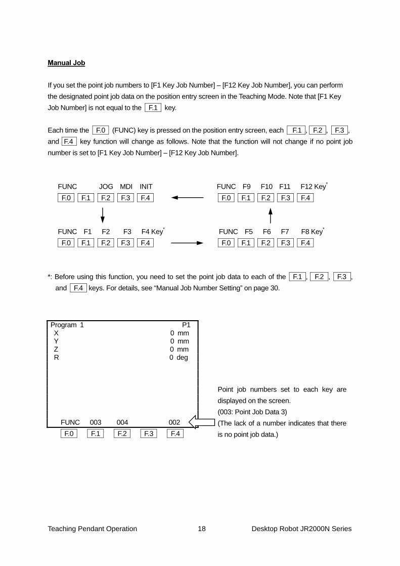
Manual Job If you set the point job numbers to [F1 Key Job Number] – [F12 Key Job Number], you can perform the designated point job data on the position entry screen in the Teaching Mode. Note that [F1 Key Job Number] is not equal to the F.1 key. Each time the F.0 (FUNC) key is pressed on the position entry screen, each .F.1.., . F.2 ., F.3 ., and .F.4 key function will change as follows. Note that the function will not change if no point job number is set to [F1 Key Job Number] – [F12 Key Job Number]. FUNC . JOG MDI .. INIT FUNC F9 F10 F11 F12 Key* F.0 F.1 F.2 F.3 F.4 F.0 F.1 F.2 F.3 F.4 FUNC F1 F2 F3 F4 Key* FUNC F5 F6 F7 .. F8 Key* F.0 F.1 F.2 F.3 F.4 F.0 F.1 F.2 F.3 F.4 *: Before using this function, you need to set the point job data to each of the F.1.., . F.2 ., F.3 .,
and F.4.. keys. For details, see “Manual Job Number Setting” on page 30.
Point job numbers set to each key are displayed on the screen. (003: Point Job Data 3) (The lack of a number indicates that there is no point job data.)
Program 1 P1 X 0 mm Y 0 mm Z 0 mm R ... 0 deg FUNC 003 . 004 002 F.0 F.1 F.2 F.3 F.4
Teaching Pendant Operation 19 Desktop Robot JR2000N Series
After switching the screen display, press the F.1 , F.2 , F.3 or F.4 key. The robot will perform the point job set to the key.
If your teaching pendant has an enable switch, press the keys while holding down the enable
switch. How to Copy the Point Coordinates You can copy the coordinates of an existing point in the following cases:
• When entering [Position Setting] in the [2-Points Position Conversion] menu • When entering [Robot Coordinate Position] in the [Calibration] menu ([Camera A210/A110
Adjustment])
Press the F.3 key while pressing the SHIFT.. key on the position entry screen. Then enter the point number of the copy source and set it. The coordinate values of the entered point number will be copied. (You can select points only within the currently selected program.)
Enter 0 to copy the work home position coordinates.
Always pay special attention to the robot’s movement in the Teaching Mode. Caution
Teaching Pendant Operation 20 Desktop Robot JR2000N Series
JOG Mode In the JOG Mode, you can shift or rotate a robot Axis to the desired position using the JOG keys on the teaching pendant and enter the position. The coordinate value of the current Arm position will be displayed on the teaching pendant LCD. Note that the RUN light on the teaching pendant will not turn on when shifting a robot Axis using the JOG keys.
X Shifts the X-Axis in the –X direction. X Shifts the X-Axis in the +X direction. Y Shifts the Y-Axis in the –Y direction. Y Shifts the Y-Axis in the +Y direction. Z Shifts the Z-Axis in the –Z direction. Z Shifts the Z-Axis in the +Z direction. R Rotates the R-Axis in the –R direction. (4-Axis model only) R Rotates the R-Axis in the +R direction. (4-Axis model only)
The distance the Axis shifts each time the above JOG keys are pressed as well as the speed at which the Axis shifts when the keys are continuously pressed can be adjusted using the numeric keys in the Teaching Environment Setting menu [JOG Speed]. (Press the T.ENV key in the Teaching Mode to display the menu.)
The movement of the Axis in the JOG mode is limited by the move area limit. If the Axis is not
able to go over certain coordinates, check [Move Area Limit] in the [Default Program Data] menu.
J.ENTR Enters the coordinates. The Point Type selection screen will be displayed when entering a new point. The screen will return to the point settings screen (referred to as base screen) when modifying a
JOG
Keys
Always pay special attention to the robot’s movement in the Teaching Mode. Caution
Teaching Pendant Operation 21 Desktop Robot JR2000N Series
registered point.
ESC Returns to the point settings screen (base screen) when modifying a position. This key is invalid when entering a new position.
JOG SPEED Changes the shifting speed (referred to as step) and shifting speed of
an Axis and shifting speed when entering positions using the JOG keys in the Teaching Mode.
F.0 Changes the F.1 – F.4 key functions. (Before using this function, you need to set the point job data to each
key. For details, see “Manual Job Number Setting” on page 30.) F.3 Switches to the MDI Mode.* F.4 Performs the mechanical initialization and shifts an Axis to its absolute
coordinates (0, 0).* *: If you have changed the functions of the ..F.1 – F.4 key by pressing the F.0 key, the point
jobs assigned to the keys will be performed instead. (See “Manual Job Number Setting” on page 30)
SHIFT + T.ENV Displays the Tool for Teaching settings screen. T.ENV Displays the Teaching Environment Setting menu. ..SHIFT + F.3 Copies the coordinate values of the designated point number.
If your teaching pendant has an enable switch, press the keys while holding down the enable switch to shift a robot Axis.
Teaching Pendant Operation 22 Desktop Robot JR2000N Series
Coordinate System
A
A
Teaching Pendant Operation 23 Desktop Robot JR2000N Series
MDI Mode In the MDI Mode, you can enter the coordinate values using the numeric keys. The Axes will not shift.
You can enter the item indicated by a >
mark on the left side of the screen.
The currently selected mode (JOG or MDI) is highlighted.
1 – 0 ________ Overwrites the figure in the cursor’s current location with the number
pressed. If the cursor is hidden, the selected number will be entered as the last digit.
. ______________ Enters a decimal point. This key is invalid if the figure already contains a
decimal point or no decimal fraction is possible.
± ______________ Reverses the plus and minus signs. This key is invalid if no negative (-) number exists.
The above keys 1 – ± are called numeric keys.
CLEAR ________ Clears the entire value. The value becomes 0.
DEL __________ Deletes the figure or decimal point in the cursor’s current location.
The cursor and the figure on the left side of the cursor then shift to the right. However, a decimal point cannot be deleted if the figure will exceed the entry range without the decimal point. If there is no cursor, the lowest figure of the decimal fraction will be deleted and the figures will shift to the right.
Program 1 P1 >.X 0 mm
Y 0 mm Z 0 mm R 0 deg FUNC . JOG MDI INIT F.0 F.1 F.2 F.3 F.4
Teaching Pendant Operation 24 Desktop Robot JR2000N Series
F.3 __________ Each time this key is pressed, the cursor line (marked with >) will switch
in the following order: X Y Z R X.
CURSOR _____ Shifts the cursor to the left. This key is invalid if the cursor is on the leftmost digit. If the cursor is hidden, press this key to display the cursor on the rightmost digit.
CURSOR ______ Shifts the cursor to the right. If the cursor is on the rightmost digit,
pressing this key will hide the cursor. This key is invalid if the cursor is hidden.
GO _____________ Shifts a robot Axis to the coordinates displayed on the LCD.
The RUN light on the teaching pendant will not turn on when shifting an Axis using the ..GO key.
J.ENTR Enters the coordinates. The Point Type selection screen will be displayed when entering a new point. The screen will return to the point settings screen (referred to as base screen) when modifying a registered point.
ESC This key is invalid when entering a new position. Returns to the point
settings screen (base screen) when modifying a position.
F.0 Changes the F.1 – F.4 key functions. (For details, see “Manual Job Number Setting” on page 30.)
F.2 Switches to the JOG Mode and replaces the coordinates displayed on the LCD with the current Axis position coordinates.*
F.4 Performs the mechanical initialization and shifts an Axis to its
absolute coordinates (0, 0).* *: If you have changed the functions of the ..F.1 – F.4 key by pressing the F.0 key, the point
jobs assigned to the keys will be performed instead. (See “Manual Job Number Setting” on page 30)
Always pay special attention to the robot’s movement in the Teaching Mode. Caution
Teaching Pendant Operation 25 Desktop Robot JR2000N Series
If your teaching pendant has an enable switch, press the keys while holding down the enable switch to shift a robot Axis.
SHIFT + T.ENV Displays the Tool for Teaching settings screen. T.ENV Displays the Teaching Environment Setting menu. ..SHIFT + F.3 Copies the coordinate values of the point designated by number.
The movement of the Axis in the MDI mode is not limited by the move area limit. If the move area limit is required, enter the position in the JOG mode or otherwise be careful not to exceed the move area limit.
If the displayed coordinate value is not the same as the current Axis position, a different Axis (X, Y,
Z, or R) will be highlighted.
Teaching Pendant Operation 26 Desktop Robot JR2000N Series
TEACHING MODE PARAMETER The teaching mode parameters form the environment settings of the Teaching Mode. Press the T.ENV key in the Teaching Mode to display the parameters.
Parameter Description Brightness Adjustment Adjust the brightness on the teaching pendant LCD.
Unit of Measure Select the displayed unit of measurement between millimeters (mm) and inches (inch).
Display Language Select the desired language from English, Japanese, German, Italian, Spanish, French, or Korean.
Go Function Set the shifting conditions of the robot Axes while the .GO. key is pressed.
JOG Function Set the shifting conditions of the robot Axes when entering positions using the JOG keys.
Tool for Teaching Set the tool settings valid only in the Teaching Mode.
Manual Job Number Setting Set the point job numbers to be performed when entering positions in the Teaching Mode.
Save on Changing Mode Select [Valid] (default) to display the Data Save confirmation screen when changing from the Teaching Mode to the Run Mode.
Key Click Select the location from which a sound will be emitted when any key on the operation panel is pressed.
Back Light on Teaching Select [OFF] to disable the teaching pendant LCD backlight in the Teaching Mode.
Coordinates Display Select the coordinates display settings on the point settings screen between [Normal] and [Detail].
You can select [Display Language] by pressing the .SHIFT + T.ENV keys from any mode.
Brightness Adjustment You can adjust the brightness of the teaching pendant LCD on this screen.
Key and Item Selection
T.ENV [Brightness Adjustment]
CURSOR key: Darker CURSOR key: Brighter
Brightness Adjustment
Teaching Pendant Operation 27 Desktop Robot JR2000N Series
Unit of Measure You can select the unit of length displayed on the teaching pendant LCD between millimeters and inches.
Key and Item Selection
T.ENV [Unit of Measure]
[Millimeters [MM] [MM/S]] [Inches [IN] [IN/S]]
Display Language You can select the language displayed on the teaching pendant LCD from the following seven items:
GO Function The robot Axes will shift to the coordinates displayed on the teaching pendant LCD if the .GO. key is pressed while teaching in the MDI mode. You can set the shifting conditions for the Axes on this screen. However, you cannot switch to the CP drive conditions.
Teaching Pendant Operation 28 Desktop Robot JR2000N Series
Select the item that you wish to change and then enter the desired value.
Trajectory of GO Function Movement
GO Function PTP Speed 100%R-Axis Rotate Speed 100%R-Axis Acceleration 100%
Absolute ModeHorizontal Move Pos'n 30mmStart Horizontal 5mmStart Down Pos'n 10mm
Example of the GO Function Selection Screen (When [Absolute Mode] is selected)
GO Function PTP Speed 100%R-Axis Rotate Speed 100%R-Axis Acceleration 100%
Relative ModeZ Move Height 100mmZ Up Distance 100mm Z Down Distance 100mm
Example of the GO Function Selection Screen (When [Relative Mode] is selected)
Z=0
Start Horizontal
Z Up Distance
Horizontal Move Pos'n
Start Down Pos'n
Z Down Distance Z Move Height
Point 2Point 1
Teaching Pendant Operation 29 Desktop Robot JR2000N Series
JOG Function You can select the speed at which the Axis shifts while teaching in the JOG mode from low, medium, and high using the JOG SPEED key. The speed can be entered using the numeric keys. The distance the Axis shifts when the JOG keys are pressed while teaching in the JOG mode can also be entered using the numeric keys.
Key and Item Selection
T.ENV [JOG Function]
Select the item that you wish to designate. The number entry screen for the selected item will appear. Enter the speed or distance and set it. The speed or distance entered here will affect the shifting of the Axis while teaching in the JOG mode afterwards.
Tool for Teaching Use this function when teaching points using a tool different from the one used in the Run mode. If the [Tool for Teaching] is set to [Valid], the tool data set in the [Setting Tool for Teaching] is valid only in the Teaching Mode. In the Run Mode, the [Tool Data] set in the [Program Data Settings] is valid.
Key and Item Selection
T.ENV [Tool for Teaching]
[Tool for Teaching] [Valid] [Invalid]
[Setting Tool for Teaching #1] [Setting Tool for Teaching #5]
JOG Function Low Speed 3mm/sMiddle Speed 10mm/sHigh Speed 20mm/sLow Step 0.05mmMiddle Step 0.2mmHigh Step 0.5mmR-Axis Low Step 0.1degR-Axis Middle Step 0.2degR-Axis High Step 1.0deg
~
Teaching Pendant Operation 30 Desktop Robot JR2000N Series
Manual Job Number Setting You can set up to 3 point job numbers for the F.1. , F.2. , F.3. , and F.4 keys. For example, set a point job number that closes the hand tool to the F.1 key when teaching a program to perform a pick & place operation. You can check if the hand tool picks up the workpiece at the teaching point in the Teaching Mode. Key and Item Selection
T.ENV [Manual Job Number Setting]
[F1 Key Job Number]
[F12 Key Job Number] Set point job numbers to [F1 Key Job Number] – [F12 Job Number]. You can perform the designated point job on the position entry screen in the Teaching Mode. Note that the [F1 Key Job Number] is not equal to the ..F.1 key. Each time the F.0 (FUNC) key is pressed on the position entry screen, the .F.1.., . F.2 ., F.3 ., and . F.4 key functions will change as follows. Note that the function will not change if no point job number is set for [F1 Key Job Number] – [F12 Key Job Number]. FUNC . JOG MDI .. INIT FUNC F9 F10 F11 F12 Key* F.0 F.1 F.2 F.3 F.4 F.0 F.1 F.2 F.3 F.4 FUNC F1 F2 F3 F4 Key* FUNC F5 F6 F7 .. F8 Key* F.0 F.1 F.2 F.3 F.4 F.0 F.1 F.2 F.3 F.4 *: The screen will indicate the point job numbers set to each key. (e.g. 003: Point job number 3)
~
Teaching Pendant Operation 31 Desktop Robot JR2000N Series
Select the key to which you wish to set point job data. The Point Job Number entry screen will appear. Enter the desired point job number and set it. After setting the point job number, press the .F.0.. (FUNC) key on the position entry screen. The indicator on the last line will change from “FUNC JOG MDI INIT” to the point job numbers set to the ..F.1 , F.2 , F.3 , and F.4 keys as shown to the right. Press the F.1. , F.2. , F.3. , or F.4 . key. The robot will perform the point job data set to the corresponding key.
If the point job number 0 (equal to no point job) is set to the keys, it will not be displayed on the position entry screen.
The ..F.0 (FUNC) key is invalid if no point job data is set for [F1 Key Job Number] – [F12 Key
Job Number] (or the point job number 0 is set to the keys).
If your teaching pendant has an enable switch, press the keys while holding down the enable switch when performing point jobs that include commands to shift a robot Axis.
Manual Job Number Setting F1 Key Job Number 3F2 Key Job Number 4F3 Key Job Number 0F4 Key Job Number 8F5 Key Job Number 12F6 Key Job Number 13F7 Key Job Number 0F8 Key Job Number 0F9 Key Job Number 15F10 Key Job Number 6F11 Key Job Number 0F12 Key Job Number 0
Program 1 P1 X 0mm Y 0mm Z 0mm R 0deg FUNC 003 004 . 008 F.0 F.1 . F.2 F.3 F.4
Always pay special attention to the robot’s movement in the Teaching Mode. Caution
Teaching Pendant Operation 32 Desktop Robot JR2000N Series
Save on Changing Mode
Select [Valid] (default) to display the Data Save confirmation screen when changing from the Teaching Mode to the Run Mode. Select [YES] to save the data and [NO] to not save the data.
Key and Item Selection
T.ENV [Save on Changing Mode]
[Valid] [Invalid]
Key Click
Select the location from which a sound will be emitted when any key on the operation panel is pressed.
Key and Item Selection
T.ENV [Key Click]
[Inside: ON Panel: ON] [Inside: OFF Panel: ON] [Inside: ON Panel: OFF]
[Inside: OFF Panel: OFF] • Inside: ON, Panel: ON Sound from both the robot and the teaching pendant • Inside: OFF, Panel: ON Sound only from the teaching pendant • Inside: ON, Panel: OFF Sound only from the robot • Inside: OFF, Panel: OFF No sound
Teaching Pendant Operation 33 Desktop Robot JR2000N Series
Back Light on Teaching
Select [OFF] to disable the teaching pendant LCD backlight in the Teaching Mode.
Key and Item Selection T.ENV
[Back Light on Teaching] [ON] [OFF]
Coordinates Display Select [Detail] to change the coordinates display on the point settings screen. (Each Axis coordinate value will be displayed to three places of decimals per line.) The default setting is [Detail]. Key and Item Selection
T.ENV [Coordinates Display]
[Normal] [Detail]
Program 1 P1 X -5.255mmY 260.352mmZ 20.25mmR 25.36degType CP Start PointLine Speed 50mm/s S.MARK E.MARK J.EXEC P.EXEC
Example of the Point Settings Screen (Detail)
Program 1 P1 X-5 Y+260 Z+20 R+25 Type CP Start PointLine Speed 50mm/s S.MARK E.MARK J.EXEC P.EXEC
Example of the Point Settings Screen (Normal)
Teaching Pendant Operation 34 Desktop Robot JR2000N Series
PROGRAM
A program consists of the program data and consecutive sets of the point data. The robot can perform various operations by running programs.
Program
Program data Point 1 Point 2 Point 3 Point 4 (Snip) Last point
Program data: Settings to control programs (e.g. program name) Point data: Settings that include the coordinates of the points at which the robot will run and the point job numbers that the robot will perform
Press the PRG.NO key on the base screen either in the Teaching Mode, External Run Mode, or Switch Run Mode. The Program Number entry screen shown to the right will appear. Entering a program number will select the program.
F.0 key: The Delete Program Number entry screen will appear. Enter the program number that you wish to delete. F.1 key: The Source Program Number entry screen will appear. Enter the program number and then enter the destination program number. The contents of the destination program will be replaced by those of the source program. F.2 key: The unregistered program number list will appear. Select a number from the list. The settings screen for the first point (Point 1) of the program will appear.
Enter a number.
Program Number 1 DEL COPY NEW LIST GLIST F.0 F.1 F.2 F.3 F.4
Teaching Pendant Operation 35 Desktop Robot JR2000N Series
F.3 key: The registered program number list will appear. Select a number from the list. The settings screen for the first point (Point 1) of the program will appear.
F.4 key: The currently selected program will be displayed as a graph. The display will
make it easier to differentiate the individual programs.
The CP points (from the CP start point to the CP end point) will be displayed as a line on the graph.
The following keys are valid on the graph display screen:
CURSOR The registered program following the currently displayed program will appear. This key is invalid if no available program is registered following the current one.
CURSOR The registered program preceding the currently displayed program
will appear. This key is invalid if there is no preceding program registered.
ENTR Displays the point settings screen (base screen) of the program.
ESC Returns to the Program Number entry screen.
CP Points
X-Y Coordinate direction 001 WORK1 Y X
Graph Display
PTP Points
Teaching Pendant Operation 36 Desktop Robot JR2000N Series
PROGRAM (POINT DATA) Entering Point Data
Press the PRG.NO key on the base screen in the Teaching Mode and enter the program number that you wish to register. If you select a new (unregistered) program, the new position entry screen for Point 1 will appear. Enter coordinates (position) and select a point type. The new position entry screen for the next point will appear. Enter the points by repeating the above procedures. If you select a CP point as a point type, the new position entry screen for the next point will appear after entering the [Line Speed].
If you want to add a point to the registered program, press the CURSOR key on the settings screen for the last point. The new position entry screen for the point to follow the last point will appear.
Coordinates (position) entry
Point type selection
New position entry screen for the next point
Repeat (Line speed entry)
Teaching Pendant Operation 37 Desktop Robot JR2000N Series
How to Modify the Point Data
First, display the settings screen for the point that you wish to change. The point settings screen is referred to as the base screen. Select the program that you wish to modify and press the SHIFT + ESC keys. The point settings screen will appear.
If you wish to designate a point number, select the first line and enter the point number. Press the .CURSOR . or .CURSOR . key to display the settings screen for the previous or next point settings screen.
Display the settings screen for the point that you wish to modify and select the desired item.
Program 1 P1 X+23.2 Y+312.5 Z+25 R+12 Type PTP Point S.MARK E.MARK J.EXEC P.EXEC
Example of the Point Settings Screen
Program 1 P1 Program number Point number X+23.2 Y+312.5 Z+25 R+12 Coordinates (Position) Type CP Start Point Point type Line Speed 50mm/s (CP) Line speed (sometimes nil) Point Job Number 3 Point job data (sometimes nil) Pallet Routine Number 6 Additional function data (sometimes nil) S.MARK E.MARK J.EXEC P.EXEC
The settings screen sometimes covers multiple pages depending on the number of the registered point job data and additional function data.
F.0 F.1 F.2 F.3 F.4
Teaching Pendant Operation 38 Desktop Robot JR2000N Series
Coordinates (Position) When you select the coordinates, the position entry screen (MDI mode) will appear. After setting the coordinates, the screen will return to the point settings screen. Point Type If you select [Type], the Point Type selection screen will appear. Select the point type that you wish to set. If you have selected a CP point, the Line Speed entry screen will appear. After entering the line speed, the screen will return to the point settings screen. Line Speed Select this item to change the line speed. The Line Speed entry screen will appear. (The [Line Speed] will not appear if you have selected a PTP Point on the Point Type selection screen.)
The maximum line speed is 800mm/s (500mm/s for the JR2200N Series). If the robot Axes reach the target position before reaching the preset line speed, a [CP Speed Over] error will be returned. In this case, reduce the line speed. Point Job Number/Additional Function Number
How to Change the Number Select the point job data number or additional function data number that you wish to change. The Point Job Number or Additional Function Number entry screen shown to the right will appear. Enter the desired number. How to Deactivate the Setting Enter 0. The point job data or additional function data set to the point will be deactivated.
F.0 key: The Delete (Point) Job Number or Delete (Additional Function) Data Number entry
screen will appear. Enter the point job number or additional function number that you wish to delete.
Enter a number.
Point Job Number 1 DEL . COPY . NEW . LIST . VIEW F.0 F.1 F.2 F.3 . F.4
Teaching Pendant Operation 39 Desktop Robot JR2000N Series
F.1 key: The Source Point Job Number or Source (Additional Function) Data Number entry
screen will appear. Enter the source number and destination number. The contents of the destination point job data or additional function data will be
replaced by those of the source data.
F.2 key: The unentered point job number or additional function number list will appear. Select a number from the list. The new entry or selection screen for the point job data or additional function data will appear. Enter the necessary commands or parameters. Pressing the ..ESC key sets the entered point job data or additional function data to the point and returns the screen to the point settings screen..
F.3 key: The registered point job number or additional function number list will appear.
Select a number from the list. The selected point job data or additional function data will be set to the point and the screen will return to the point settings screen.
F.4 key: The settings screen for the currently displayed point job data number or additional
function data number will appear. You can modify the data on this screen. How to Add a Function You can set multiple additional functions to a point. Note that you cannot set the same functions to one point. For example, you can set additional functions [PTP Condition] and [Tool Data] to the same point; however, you cannot set the [PTP Condition] to the same point twice.
First, display the settings screen for the point to which you wish to add the point job data or the additional function data.
Select the last item of the point settings screen and press the CURSOR key. The point job data and additional function data that can be set to the point will be displayed under the point data items as shown to the right. Select the point job data or additional function data that you wish to set and then enter a number. (Items that have not been set to the point have no number on their right side.)
Program 1 P1 1/2 X+23.2 Y+312.5 Z+25 R+12 Type PTP PointCondition Number 5Job before Moving Job while Moving Point Job Number PTP Condition Number Tool Number Pallet Routine Number Execute Condition Number Work Adjustment Number S.MARK E.MARK J.EXEC P.EXEC
Teaching Pendant Operation 40 Desktop Robot JR2000N Series
If you enter an unregistered number on the number entry screen for the selected point job or additional function, the new entry or selection screen for point job data or additional function data will not appear.
For details on the point job data and additional function data, see the Features I (Point Teaching)
operation manual. Transform into Relative
Select [Transform into Relative] to convert all the point coordinates in the currently selected program into the relative coordinates. Specifically, deduct the values of the X-, Y-, Z-, and R-Axes for Point 1 from those of each point (from Point 1 to the last point) and set the differences as the relative coordinates of each point. (The coordinates of Point 1 should be X: 0, Y: 0, Z: 0, R: 0.) Coordinates of the work home position and the points that have no number (included in the program data) are not converted. Key and Item Selection
EDIT [Transform into Relative]
Note that you cannot transform the point coordinates from relative into absolute.
Teaching Pendant Operation 41 Desktop Robot JR2000N Series
How to Insert a Point Display the settings screen for the point in front of which you wish to insert a point.
Key and Item Selection
EDIT [Insert a Point]
If you select [Insert a Point], the new position entry screen will appear. Enter the position where the point is to be inserted and select the point type of the point to be inserted. Each point that comes after the inserted point will shift down by one number.
Inserted Currently displayed point (Before insertion) (After insertion) How to Delete a Point Display the settings screen for the point that you wish to delete.
Key and Item Selection
EDIT [Delete a Point]
If you select [Delete a Point], the currently displayed point will be deleted and the settings screen for the next point will appear. Each point that comes after the deleted point will shift up by one number.
P1 P5P2 P4
.P1 P4P3P2
P3 Currently displayed point
Deleted(After deletion)
(Before deletion)
P1 P4P2 P3
P1 P5P4P2 P3
Teaching Pendant Operation 42 Desktop Robot JR2000N Series
Block Editing You can edit (delete, move, copy, mirror copy, offset, position data rotation) a block of points between certain points in a program. Display the Block Editing Menu according to the following procedures: Press the EDIT key on the point settings screen. The Editing Points Menu will appear. Select [Block Editing] from the menu. Enter the start point number (block start number) and end point number (block end number) that you wish to edit. The Block Editing Menu shown below will appear. Select the item that you wish to edit from the menu.
Press the ..F.4 (ALL) key on the Block Start Number entry screen. All points in the program will be selected. (The Block End Number entry screen will not appear.)
Press the ..F.4 (LAST) key on the Block End Number entry screen. The last point number in the program will be entered.
Press the F.0 (S.MARK) key on the point settings
screen. The current point number will be set as the default block start number.
If the F.1 (E.MARK) key is pressed, the current point number will be set as the default block end number.
Select [Block Editing] from the Editing Points menu.
Teaching Pendant Operation 43 Desktop Robot JR2000N Series
Delete Block Points You can delete a block of points between certain points in a program. Select [Delete Block Points] from the Block Editing Menu. The Delete Block Points confirmation screen will appear. Select [YES].
Each point that comes after the deleted points will shift forward. Move Block Points You can move a block of points between certain points in a program. Note that you cannot move the block points into other programs.
Select [Move Block Points] from the Block Editing Menu. The Destination Number entry screen will appear.
The designated block will move in front of the destination point. Enter the destination number.
If the F.3 (TOP) key is pressed, 1 will be entered as the destination number. If the F.4 (LAST) key is pressed, the number equal to the last point number plus 1 will be entered as the destination number.
You cannot select a number in the block as the destination number.
P1 P4 P5 P6P2 P3
P1 P2 P3Block Points
(Before deletion)
(After deletion)
Move Block Points
Enter a number.
Destination Number 8 TOP LAST
Example of the Destination Number Entry Screen
P1 P7P4 P5 P6P2 P3 P8
P1 P4P6 P7 P3P2 P5 P8
(Before moving)
(After moving)
Destination Number
Block Points
Block Points
Teaching Pendant Operation 44 Desktop Robot JR2000N Series
Copy Block Points You can copy a block of points between certain points in a program. You can designate the copy count and parallel shifting distance in the X and Y directions. Note that you cannot copy the block into other programs. Select [Copy Block Points] from the Block Editing Menu. The X Distance entry screen will appear. Enter the parallel shifting distance of the copied block in the X direction. After entering the X distance, the Y Distance entry screen will appear. Enter the parallel shifting distance of the copied block in the Y direction. After entering the Y distance, the Copy Times entry screen will appear. Enter the desired number of copies.
After entering the copy times, the block will be copied and the screen will return to the point settings screen. The copied block will be inserted just behind the original block. The coordinates of the copied points may exceed the operating range of the robot. After copying the block points, be sure to perform [Checking Data] in the Test Menu. The following example shows the point shifting when the Point Block P1 – P3 is copied twice.
(P4 (before insertion) will be P10 after insertion.)
Teaching Pendant Operation 45 Desktop Robot JR2000N Series
Mirror Copy You can make a mirror copy of a block of points between certain points in a program. Note that you cannot copy the block points into other programs. Select [Mirror Copy (Right-Left)] or [Mirror Copy (Front-Back)] from the Block Editing Menu. The Mirror Position X or Y entry screen shown to the right will appear. Enter the coordinates of the mirror position for X or Y. After entering the mirror position for X or Y, a mirror copy will be made and the screen will return to the point settings screen. The copied block will be inserted just after the original block. The coordinates of the copied points may exceed the operating range of the robot. After copying the block points, be sure to perform [Checking Data] in the Test Menu.
Mirror Copy (Right-Left)
Enter a number.
Mirror Position X 0.25mm
Example of the Mirror Position X Entry Screen
P1 P7P4 P5 P6P2 P3 P8
P1 P4P4 P2 P3P2 P3 P5
(Before copying)
(After copying)
Block Points
Copied Block
Mirror Copy (Front-Back)
Mirror Position (Y)
Mirror Copy (Right-Left)
Mirror Position (X)
Teaching Pendant Operation 46 Desktop Robot JR2000N Series
Offset You can move a point coordinate block between certain points in a program.
Select [XYZR Offset] from the Block Editing Menu. The X Offset entry screen shown to the right will appear. Enter the desired shifting distance. After entering the X offset, enter the Y offset, Z offset, and R offset in order.
Enter 0 if you do not want to move the block in a particular direction.
The block points will move as shown to the left if you have entered only the X Offset.
The entered offsets will be added to all points in the block and then the screen will return to the point settings screen. The coordinates of the offset points may exceed the operating range of the robot. After editing the offset, be sure to perform [Checking Data] in the Test Menu.
XYZR Offset
Enter a number. X Offset 0.25mm
Teaching Pendant Operation 47 Desktop Robot JR2000N Series
Block Rotation You can rotate a point coordinate block between certain points in a program.
Select [Block Rotation] from the Block Editing Menu. The Center X entry screen shown to the right will appear. Enter the X coordinate for the center of rotation.
After entering the X coordinate, the Center Y entry screen will appear. Enter the Y coordinate for the center of rotation.
After entering the Y coordinate, the Rotate Angle entry screen will appear. Enter the desired rotation angle. After entering the rotation angle, the block will be rotated and the screen will return to the point settings screen.
Example If you rotate Point 01 (P1) and Point 02 (P2) by +90 or –90 degrees, the shifting destinations are P1’ and P2’ as shown below.
Block Rotation
Enter a number.
Center X 0mm
Example of the Center X Entry Screen
Teaching Pendant Operation 48 Desktop Robot JR2000N Series
Block Setting Same Value
You can set the designated additional function number to a block of points (between the designated points). Additional functions already set to the points will be replaced by the additional function that is designated in the [Block Setting Same Value] process. If the block contains any point that the designated additional function cannot be set to, that point will not be affected. (CP points for PTP condition, for example. See the table on Page 20 of the Basic Instructions operation manual for the correlation between the point types and additional functions)
Press the EDIT key on the point settings screen and select [Block Setting Same Value] from the EDIT menu. Enter the start point number (block start number) and end point number (block end number) for which you wish to set the same line speed or additional function data. The Block Setting Same Value Menu will appear.
Press the ..F.4 (ALL) key on the Block Start Number
entry screen. All points in the program will be selected. (The Block End Number entry screen will not appear.)
Press the ..F.4 (LAST) key on the Block End Number entry screen. The last point number in the program will be entered.
Block Setting Same Value Reset Line Speed Multiple Line Speed PTP Condition Number CP Condition Number Tool Number Pallet Routine Number Execute Condition Number Work Adjustment Number
Block Setting Same Value Menu
Select [Block Setting Same Value] from the edit menu.
Enter a block start number.
Enter a block end number.
Block Setting Same Value
Press the EDIT key on the point settings screen.
Teaching Pendant Operation 49 Desktop Robot JR2000N Series
Reset Line Speed You can set the same line speed between certain points (i.e. point block) in a program. If the block contains any PTP point, the point will not be affected.
Select [Reset Line Speed] from the Block Setting Same Value Menu and enter the desired speed.
The maximum line speed is 800mm/s.* If a larger number is entered, the speed will be set as 800mm/s. *: The maximum line speed for the JR2200N Series is 500mm/s.
Reset Line Speed Rate You can set the same line speed rate between certain points (point block) in a program. If the block contains any PTP point, the point will not be affected.
Select [Multiple Line Speed] from the Block Setting Same Value menu and enter the desired percentage.
Reset Line Speed
Enter a number.
Line Speed 10mm/s
Multiple Line Speed
Enter a number.
Line Speed Rate 100%
Teaching Pendant Operation 50 Desktop Robot JR2000N Series
Reset Additional Function Data Number You can reset the additional function data between certain points (i.e. block point) in a program to the designated additional function data. If any point in the block contains the same function data as the designated additional function data, only the data number will be reset to the designated data number. If the block contains any point that the designated function cannot be set to, the point will not be affected. (CP points for PTP condition, for example. See the table on Page 20 of the Basic Instructions operation manual for the correlation between the point types and additional functions)
From the Block Setting Same Value Menu, select the additional function (e.g. [PTP Condition Number]) that you wish to set and enter the desired number.
F.0 key: The Delete (Additional Function) Data Number entry screen will appear. Enter the
additional function number that you wish to delete.
F.1 key: The Source (Additional Function) Data Number entry screen will appear. Enter the source number and destination number. The contents of the destination additional function data will be replaced by those of the source data.
F.2 key: The unregistered additional function number list will appear. Select a number from
the list. The new entry or selection screen for the additional function data will appear. Enter the necessary parameters. Pressing the ..ESC key sets the entered additional function data to the point and returns the screen to the point settings screen.
F.3 key: The registered additional function number list will appear. Select a number from the
list. The selected additional function data will be set to the point and the screen will return to the point settings screen.
F.4 key: The settings screen for the currently displayed additional function data number
will appear. You can modify the data on this screen.
Enter a number.
PTP Condition Number 1 DEL COPY NEW LIST VIEW F.0 F.1 F.2 F.3 F.4
Teaching Pendant Operation 51 Desktop Robot JR2000N Series
POINT RUN In the Teaching Mode, any point in a program can be run. (If the CP drive is selected, the robot will run from [CP Start Point] through [CP End Point].) The robot will perform operations such as the point job data and additional function data in exactly the same way as in the Run Mode. This function is useful when you wish to check which points designated by [Execute Condition] the robot will run.
If you set the point job data or sequencer program data to wait for a start signal from I/O or COM1,
the robot will wait for a start signal when running points in the Teaching Mode. Press the F.4 key on the point settings screen. The robot will run the currently displayed point and the screen will change to the settings screen for the next point.
Be sure not to perform a test run when the point settings screen displays a CP point other
than the CP start and end points (e.g. CP passing point). If the currently selected point is a CP start point, the robot will run a program from the CP start point through the CP end point, without stopping at the CP passing point or the CP arc point.
See the examples of the robot’s running process by pressing the F.4 key one time on the settings
screen for P1.
(e.g. 1) (e.g. 2) P2: PTP point P4 P2: CP passing point P4
Current tool position Current tool position In Example 1, the robot runs P1 (shifts its Axes to the point and performs the point job data and additional function data) and then stops at P1. The screen will change to the settings screen for P2.
P1: PTP point
P3: PTP point
P1: CP start point
P3: CP end point
Always pay special attention to the robot’s movement in the Teaching Mode. Caution
Teaching Pendant Operation 52 Desktop Robot JR2000N Series
In Example 2, the robot runs P1 P2 P3 in order (shifts its Axes to the point and performs the
point job data and additional function data) and then stops at P3. The screen will change to the settings screen for P4. After running the last point of the program, press the F.4 key again. The robot will run the work home position or the first point depending on [Cycle Mode] settings in the [Default Program Data] menu. ([1 Cycle Playback]: work home position, [Continuous Playback]: first point)
Press the F.4 key on the point settings screen. The robot will run the currently displayed point and the screen will change to the settings screen for the next point.
An & mark will appear in the first line of the screen. Press the F.4 key to run the next point. If an & is not displayed, the currently displayed point will be run again if the F.4.. key is pressed.
When an & is displayed on the point settings screen, the same additional function data will be
repeated at the points following the current point. If the additional function data [Pallet Routine] is set to P2, after running P2, an & will appear on the
settings screen for P2. Each time the F.4 key is pressed, the robot Axes will shift to the next point on the pallet.
The & mark will disappear if either the MENU , EDIT , CURSOR , or CURSOR . key is
pressed or when the settings screen for the next point is displayed. Note that the pallet counter will be reset if the & mark disappears while running the [Pallet Routine].
Program 1 & P1 X+23.2 Y+312.5 Z+25 R+12 Type PTP PointPoint Job Number 6 S.MARK E.MARK J.EXEC P.EXEC F.0 F.1 . F.2 . F.3 F.4
Teaching Pendant Operation 53 Desktop Robot JR2000N Series
PROGRAM (PROGRAM DATA) Name Editing
You can give names to registered programs to identify the contents.
Key and Item Selection
MENU [Program Data Settings]
[Program Name]
When entering characters, the Character entry screen shown to the right will appear.
You can use 40 – 120 characters in combination to name the program. (Up to 120 characters can be entered when using the teaching pendant. When using the PC, the maximum number of characters is 40 depending on the character type (e.g. Chinese characters).) Up to 36 characters* will be displayed on the registered program list and up to 40 characters* (the maximum number of characters per line) will be displayed on the screen in the Switch Run Mode. The rest of the characters will be omitted. (*: Characters can be entered using the teaching pendant)
Character assignment list
Program 4 Program Name [1] .[2]ABC . [3]DEF [4]GHI [5]JKL .….[6]MNO [7]PQRS [8]TUV [9]WXYZ [-] [0]SPACE .[.] _ A
Example of the Character Entry Screen
Teaching Pendant Operation 54 Desktop Robot JR2000N Series
Work Home The following explains how to set the work home position in the currently selected program. Key and Item Selection
MENU [Program Data Settings]
[Work Home] Coordinates
[Type] [Point Job Number]
The [Point Job Number] indicator will not be displayed on the point settings screen if no point job
data is set to the point. Select [Work Home]. The Work Home settings screen shown to the right will appear. Select the item that you wish to change then select the item that you wish to set instead or enter a number. Note that the point type for the work home position is either the [PTP Point] or [CP Start Point]. The [Point Job Number] indicator will not be displayed on the point settings screen if no point job data is set to the point. To display the point job data items, press the . CURSOR key when the [Type] is highlighted. If you set 0 as the point job number, you can deactivate the point job settings. The point job set to the work home position will be performed when the robot Axes return to the work home position after one cycle of operation.
Program 1 Work Home X+23.2 Y+312.5 Z+25 R+12 Type PTP PointPoint Job Number 1 S.MARK E.MARK J.EXEC P.EXEC
Work Home Settings Screen
Teaching Pendant Operation 55 Desktop Robot JR2000N Series
Job on Start of Cycle Set the point job that will be performed when starting operation. If [Cycle Mode] is set to [Continuous Playback], it will be performed only when receiving the start signal. The point job set here will be performed after the [Job on Start of Cycle] included in [Run Mode Parameter]. The difference between [Job on Start of Cycle] included in [Program Data Settings] and [Job on Start of Cycle] included in [Run Mode Parameter]I is that the point job set in the [Job on Cycle Mode] included in the program data settings can be set to any program.
Key and Item Selection
MENU [Program Data Settings]
[Job on Start of Cycle] Cycle Mode Select the cycle mode of the currently selected program between [1 Cycle Playback] and [Continuous Playback].
Key and Item Selection
MENU [Program Data Settings]
[Cycle Mode] [1 Cycle Playback]
[Continuous Playback]
PTP Condition Set the PTP condition in the currently selected program. All the PTP movements of the robot Axes in the currently selected program are affected by the [PTP Condition] set in this process (excluding the movement from the point to which the additional function data [PTP Condition] is set).
Key and Item Selection
MENU [Program Data Settings]
[PTP Condition]
Teaching Pendant Operation 56 Desktop Robot JR2000N Series
CP Condition Set the CP condition in the currently selected program. All the CP movements of the robot Axes in the current program are affected by the [CP Condition] set in this process (excluding the movement from the point to which the additional function data [CP Condition] is set).
Tool Data Change the tool data in the currently selected program. Key and Item Selection MENU [Program Data Settings]
[Tool Data] In the [Direct TCP-XY Setting], you can calculate [TCP-X] and [TCP-Y] positions by pointing to the same point twice. How to Set [Direct TCP-XY Setting] Select [Direct TCP-XY Setting]. The position entry screen shown to the right will appear. Point to any point with the tool tip and then set the position coordinates. Rotate the R-Axis (by approximately 90 degrees) and point to the same point with the tool tip again. After setting the position coordinates, the calculated result will be written to the program data in the currently selected program and then the screen will return to the Tool Data settings screen.
Point a Position X 0mm Y 0mm Z 0mm R 0deg FUNC JOG MDI INIT
Teaching Pendant Operation 57 Desktop Robot JR2000N Series
Move Area Limit Change the move area limit in the currently selected program. Key and Item Selection
MENU [Program Data Settings]
[Move Area Limit] [X Upper Limit] [Y Upper Limit] [Z Upper Limit] [R Upper Limit] [R Lower Limit] [Copying to All Programs]
The movement of the Axes in the MDI mode is not limited by the move area limit. If a move area
limit is required, enter the position in the JOG mode or otherwise be careful not to exceed the move area limit.
Position Data Type Change the position data type in the currently selected program. Key and Item Selection MENU [Program Data Settings]
[Position Data Type] [Absolute] [Relative] [Moving Amount]
You can transform the point (from Point 01 to the last point) coordinates in the currently selected program from absolute into relative.
Teaching Pendant Operation 58 Desktop Robot JR2000N Series
Workpiece Weight Change the workpiece weight in the currently selected program. Key and Item Selection
MENU [Program Data Settings]
[Workpiece Weight] [8 Kg] [11 Kg]
This item has not been set for the JR2200N Series.
Teaching Pendant Operation 59 Desktop Robot JR2000N Series
POINT JOB DATA The point job data is a set of commands and logic operations that is performed at job points. The robot will perform point jobs selected from the point job number list on the point settings screen. Depending on the point type set to the point, selection may not be possible. (See the table on Page 20 of the Basic Instructions operation manual) You can create point job data Nos. 01 – 100 in the Teaching Mode. Point job data Nos. 101 – 200 can be created in the Customizing Mode. Before teaching new point job data or modifying registered point job data, you need to display the settings screen. Display the settings screen for the point job data that you wish to modify according to either of the following methods: Method 1 Press the MENU key on the point settings screen and select [Point Job Settings]. The Point Job Number entry screen will appear. Enter the desired number. Method 2 Select [Job before Moving], [Job while Moving], [Point Job Number], or [Job while CP Moving] on the point settings screen. The Point Job Number entry screen will appear. Enter the desired number.
Point Job 1 1/3 001 set #genOut3 002 delay 200 003 if 004 ld #genIn1 005 ani pallet[1].flag 006 ldi m3 007 and #genOut2 008 orb 009 then 010 loopPallet 1,5 011 callJob 25 012 pulse #genOut11,250
Example of the Point Job Data Settings Screen
Enter a number.
Point Job Number 1 . DEL COPY NEW LIST VIEW F.0 F.1 F.2 F.3 F.4
Example of the Point Job Number Entry Screen
Teaching Pendant Operation 60 Desktop Robot JR2000N Series
Select the last item of the point settings screen and press the CURSOR key. The point job data and additional function data can be set to the point will be displayed under the point data items.
If you select Method 1, enter a point job number or select a point job number from the list to display the settings screen for the entered or selected point job data. If you select Method 2, press the F.4 key on the Point Job Number entry screen to display the settings screen for the currently displayed point job data number.
F.0 key: The Delete (Point) Job Number entry screen will appear. Enter the point job
number that you wish to delete.
F.1 key: The Source Point Job Number entry screen will appear. Enter the source number and destination number. The contents of the destination point job data will be replaced by those of the source data.
F.2 key: The unregistered point job number list will appear. Select a number from the list.
The new entry or selection screen for the point job data will appear. Enter the necessary commands or parameters. Pressing the ..ESC key sets the entered point job data to the point and returns the screen to the point settings screen.
F.3 key: The registered point job number list will appear. Select a number from the list. The
selected point job data will be set to the point and the screen will return to the point settings screen.
F.4 key: The settings screen for the currently displayed point job data number will appear.
You can modify the data on this screen. (This key is invalid in Method 1.)
For more details on the point job data, see the Features I (Point Teaching) operation manual.
Teaching Pendant Operation 61 Desktop Robot JR2000N Series
Command Entry Entering point job data is adding commands to the last line of the command line. Select the last command number (that contains no command) on the Point Job Data settings screen.
Select a command number on the Point Job Data settings screen. The Point Job Command Category selection screen shown to the right will appear.
Select the command type (category) that you wish to enter.
Select a command type (category). The selection screen for commands that belong to the command type (category) will appear as shown to the right.
Select the command that you wish to enter.
After selecting a command, the Parameter entry or selection screen will appear. Depending on the commands, there may be multiple parameters or no parameters. Enter or select the required parameter. (For example, the [set] command requires the [Output Destination] as a parameter.) Depending on the commands, you need to select the entry method when entering parameters. For example, if you select the [outLCD] command, select [String] or [Expression] as the entry method.
outLCD 7,4,"PULSE": Displays the string PULSE on the teaching pendant LCD.
The [outLCD] command requires three parameters: the string, the row, and the column on the LCD. (The row and the column are required to display the string.) After entering the row and the column, the
Select Category ON/OFF Output Control if Branch, Wait Condition Condition Delay, Data In, Wait Start Pallet Control Execute Flow Control for, do-loop Move LCD Control COM Input/Output Variable, Comment, System Control Camera, Z Adjustment
Point Job Command Category Selection Screen
ON/OFF Output Control set reset pulse invPulse delaySet delayReset onoffBZ dataOut dataOutBCD
Example of the Command Selection Screen
Teaching Pendant Operation 62 Desktop Robot JR2000N Series
selection screen for [String] and [Expression] will appear. Select the [String] and enter PULSE. (The quotation marks (““) which enclose the string (PULSE in this example) will be entered automatically.)
outLCD 7,4,#sv$(24) + #sv$(25): Displays the value of the combined string variables #sv$(24)
and #sv$(25) on the teaching pendant LCD.
The [outLCD] command requires three parameters: the string, the row, and the column on the LCD. (The row and the column are required to display the string.) After entering the row and the column, the selection screen for [String] and [Expression] will appear. Select the [Expression] and enter #sv$(24) + #sv$(25) .
When entering a number as a parameter, you can select a variable or an expression instead of a value if an EXP mark is displayed at the right bottom of the number entry screen (above the F.4 key). Enter the F.4 key to display the character entry screen and enter the variable or expression you wish to set.
After entering or selecting parameter(s), the registered command will be entered into the selected command number and the screen will return to the Point Job Data settings screen shown to the right. If you wish to continue to enter commands, select the last command number (that contains no command: 003 on this screen). When you have finished entering commands, press the ..ESC key on the Point Job Data settings screen.
Point Job 1 001 set #genOut3 002 outLCD 7,4,#sv$(24) + #sv$(25) 003
Example of the Point Job Data Settings Screen
Enter a number.
Input Bit Number 1 EXP
Example of the Number Entry Screen
Teaching Pendant Operation 63 Desktop Robot JR2000N Series
Command Change There are two ways to modify the point job data command: changing the command in the command category (e.g. [set] [pulse]) and changing the command category (e.g. [set] [waitStart]).
Changing the Command in the Command Category Select the command that you wish to change on the Point Job Data settings screen. The Command selection screen will appear. Select a new command on the selection screen. The highlighted command will be deleted and replaced by the newly selected command.
Changing the Command Category Display the settings screen for the point job data that you wish to modify and highlight the command that you wish to change. Press the EDIT key and select [Change a Command]. The Command Category selection screen will appear. Select the command category and the command that you wish to change and enter or select the necessary parameter(s).
Command Insertion You can insert a new command in front of the highlighted command. For example, highlight the command number 004 line to insert a new command in front of command number 003. Key and Item Selection
EDIT [Insert a Command]
Select [Insert a Command]. The Command Category selection screen will appear. Select the command category and the command that you wish to insert and enter or select the necessary parameter(s).
Command Delete You can delete the currently highlighted command. Highlight the command that you wish to delete. Key and Item Selection
EDIT [Delete a Command]
Select [Delete a Command]. The highlighted command will be deleted and the commands following the deleted command will shift upward.
Teaching Pendant Operation 64 Desktop Robot JR2000N Series
Block (Command) Delete Key and Item Selection
EDIT [Edit Block Commands]
[Delete Block Steps] Select [Delete Block Steps]. The Block Start Number entry screen will appear. Select the start command number that you wish to delete. After entering the block start number, the Block End Number entry screen will appear. Enter the end command number. After entering the block end number, the command block will be deleted and the screen will return to the settings screen. The commands following the deleted block will shift forward as below.
[Move Block Steps] Select [Move Block Steps]. The Block Start Number entry screen will appear. Enter the start command number that you wish to move. After entering the block start number, the Block End Number entry screen will appear. Enter the end command number. After entering the block end number, the Destination Number entry screen will appear. Enter the destination command number of the location where you wish to move the command block. After entering the destination number, the command block will be moved and the screen will return to the settings screen.
Teaching Pendant Operation 65 Desktop Robot JR2000N Series
Block (Command) Copy
Key and Item Selection EDIT
[Edit Block Commands] [Copy Block Steps]
Select [Copy Block Steps]. The Block Start Number entry screen will appear. Enter the start command number that you want to copy. After entering the block start number, the Block End Number entry screen will appear. Enter the end command number. After entering the block end number, the Destination Number entry screen will appear. Enter the command number of the location where you wish to copy the block. After entering the destination number, the block command will be copied in front of the destination command and the screen will return to the settings screen.
Selected command block Point Job Name Editing The following explains how to enter a point job name. This process is applied both for entering a new name and for modifying a registered name. First, display the point job data settings screen. Key and Item Selection
EDIT [Edit Point Job Name]
Select [Edit Point Job Name] from the Edit Menu. The Character entry screen shown to the right will appear.
Enter the desired name.
Program Name [1] [2]ABC [3]DEF [4]GHI [5]JKL [6]MNO [7]PQRS [8]TUV [9]WXYZ [-] [0]SPACE [.] _ A
Example of the Character Entry Screen
Teaching Pendant Operation 66 Desktop Robot JR2000N Series
You can use 40 – 120 characters in combination to name the program. (Up to 120 characters can
be entered when using the teaching pendant. When using the PC, the maximum number of characters will be 40 depending on the character type (e.g. Chinese characters).) Up to 36 characters* will be displayed on the registered program list and up to 40 characters* (the maximum number of characters per line) will be displayed on the screen in the Switch Run Mode. The rest of the characters will be omitted. (*: Characters can be entered using the teaching pendant)
Import Merge Select [Import Merge] from the Edit Menu. The Source Point Job Number entry screen will appear. After entering the number, the contents of the entered point job data will be moved behind the last command line of the currently selected point job data. Key and Item Selection
EDIT [Import Merge]
How to Display the Designated Number You can display the desired command by designating the number. Using this function enables you to display the desired command quickly if there are multiple command lines. You do not need to press the .CURSOR key many times. First, display the settings screen for the point job data that includes the desired command. Key and Item Selection
EDIT [Change Command Number]
Select [Change Command Number]. The Change Command Number entry screen will appear. Enter the command number that you wish to display. After entering the command number, the settings screen that includes the entered command number will appear.
Teaching Pendant Operation 67 Desktop Robot JR2000N Series
SEQUENCER PROGRAM DATA The sequencer program data is a set of logical operation commands for controlling I/O signals, etc. It is always activated in the Switch Run Mode and the External Run Mode. You can create sequencer program data Nos. 01 – 50 in the Teaching Mode. Sequencer program data Nos. 51 – 100 can be created in the Customizing Mode.
Before teaching a new sequencer program or modifying a registered sequencer program, you need to display the settings screen. Display the settings screen for the sequencer program data that you wish to modify according to either of the following methods:
Method 1 Press the MENU key on the point settings screen and select [Sequencer Settings].
Method 2 Press the MENU key on the point settings screen and select [Run Mode Parameter] and [Job and Sequencer on Run Mode] in order.
If you select Method 1, enter a sequencer number or select a sequencer number from the list to display the settings screen for the entered or selected sequencer program data. If you select Method 2, press the F.4 key on the Sequencer Number entry screen to display the settings screen for the currently displayed sequencer program data number.
Sequencer 1 001 ld #sysIn15 002 or #sysOut15 003 ani #sysIn16 004 out #sysOut15 005
Example of the Sequencer Data Setting Screen
Enter a number. Sequencer Program on Run Mode 1 DEL COPY NEW LIST VIEW
F.0 F.1 F.2 F.3 F.4
Example of the Sequencer Number Entry Screen
Teaching Pendant Operation 68 Desktop Robot JR2000N Series
F.0 key: The Delete (Sequencer Program) Data Number entry screen will appear. Enter the
sequencer number that you wish to delete.
F.1 key: The Source (Sequencer Program) Data Number entry screen will appear. Enter the source number and destination number. The contents of the destination sequencer program data will be replaced by those of the source data.
F.2 key: The unregistered sequencer number list will appear. Select a number from the list.
The selected sequencer program data settings screen (includes no contents) will appear.
F.3 key: The registered sequencer number list will appear. Select a number from the list.
The selected sequencer program data settings screen will appear.
F.4 key: The settings screen for the currently displayed sequencer program data number will appear. You can modify the data on this screen. (This key is invalid in Method 1.)
The method of entering and editing commands is exactly the same as that for the point job data.
To set names to the sequencer program data, press the EDIT key on the sequencer program data settings screen. The Name Editing screen will appear.
Before performing the registered sequencer program data, set the registered sequencer number to [Sequencer Program on Run Mode] according to the procedures below:
MENU [Run Mode Parameter]
[Job and Sequencer on Run Mode] [Sequencer Program on Run Mode]
Enter a sequencer number.
Entering 0 will deactivate (not perform) the sequencer program data. The set sequencer program data will be activated soon after switching to the External Run Mode
or the Switch Run Mode. For more details on the sequencer program data, see the Features III (Run Mode Parameter/ Sequencer) operation manual.
Teaching Pendant Operation 69 Desktop Robot JR2000N Series
ADDITIONAL FUNCTION DATA Select the additional function data you wish to set from the additional function data number list on the point settings screen. The designated additional function is set to job points. Depending on the point type set to the point, selection may not be possible. (See the table on Page 20 of the Basic Instructions operation manual) You can create additional function data Nos. 01 – 50 in the Teaching Mode. Further, additional function data Nos. 51 – 100 can be created in the Customizing Mode. Additional function data consists of the following six items: 1. PTP Condition: The contents are the same as those set in the program data. Use this item to change the settings between designated points only.
2. CP Condition: The contents are the same as those set in the program data. Use this item to change the settings only between designated points.
3. Tool Data: The contents are the same as those set in the program data. Use this item when you wish to use different tool data, set in the program data, between designated points.
4. Pallet Routine: The pallet is the offset of the coordinates from the standard point. It has a counter function. For details, see “Pallet Routine” on Page 32 of the Functions I operation manual.
5. Execute Condition: Use this item to determine whether or not to run the designated point. If the point is not run, the robot Axes will skip the point and shift to the
next point. 6. Workpiece Adjustment: You can adjust the designated position (coordinates) according to the
values entered in the [Workpiece Adjustment] menu.
Method 1 Press the MENU key on the point settings screen and select [Additional Function Data Settings]. Set the additional function data (e.g. [PTP Condition Settings]) and enter an additional function data number. Method 2 Enter an additional function data number (e.g. [PTP Condition Settings]) on the point settings screen.
Select the last item of the point settings screen and press the CURSOR key. The point job data and additional function data that can be set to the point will be displayed under the point data items.
Teaching Pendant Operation 70 Desktop Robot JR2000N Series
If you select Method 1, enter an additional function number or select an additional function number from the list to display the settings screen for the entered or selected additional function data. If you select Method 2, press the F.4 key on the Additional Function Number entry screen to display the settings screen for the currently displayed additional function data number. F.0 key: The Delete (Additional Function) Data Number entry screen will appear. Enter the
additional function number that you wish to delete.
F.1 key: The Source (Additional Function) Data Number entry screen will appear. Enter the source number and destination number. The contents of the destination additional function data will be replaced by those of the source data.
F.2 key: The unregistered additional function number list will appear. Select a number from
the list. The selected additional function data settings screen (includes no contents) will appear.
F.3 key: The registered additional function number list will appear. Select a number from the
list. The selected additional function data settings screen will appear.
F.4 key: The settings screen for the currently displayed additional function data number will appear. You can modify the data on this screen. (This key is invalid in the Method 1.)
You need to create only the additional function data [Execute Condition] by entering commands. The method of entering and editing commands is exactly the same as that for the point job data.
You can set names to the additional function data [Pallet Routine] and [Workpiece Adjustment].
Press the EDIT key on the additional function data settings screen. The Name Editing screen will appear.
For more details on the additional function data, see the Features I (Point Teaching) operation
manual.
Teaching Pendant Operation 71 Desktop Robot JR2000N Series
TEACHING DATA COPY, DELETE, CONVERSION
Program List
Please refer to the program list if you need to check a registered program and its number.
Key and Item Selection MENU [Teaching Data Copy, Delete, Conversion]
[Program] [Program List]
Select [Program List]. The registered program list will appear. Unentered program numbers will not appear. You can select a program from the list.
You can get the same result if you press the PRG.NO key and then press the ..F.3 key on the base screen.
Select Item 03 30 Points 07 TEST 1 08 20 Points 09 WORK 1 16 WORK 2 17 TEST 55
Example of the Registered Program List
Teaching Pendant Operation 72 Desktop Robot JR2000N Series
Copy You can copy any registered program, point job data, or additional function data and modify it to create new one.
Key and Item Selection MENU [Teaching Data Copy, Delete, Conversion]
Select [Copy xxx]. The Source xxx Number entry screen shown to the right will appear. (xxx on the screen indicates either of Program, Point Job, or Data.) Enter a source number for each data.
Press the F.3 key on the Source Number entry screen. The registered program or point job data or additional function data list will appear. You can select the desired program or data from the list.
Enter a number.
Source xxx Number 1 LIST F.0 F.1 F.2 F.3 F.4
Teaching Pendant Operation 73 Desktop Robot JR2000N Series
After entering the source number, the Destination Number entry screen will appear. Enter a destination number for the copy. (xxx on the screen indicates either of Program, Job, or Data.)
On the Destination Number entry screen, press the F.2 (NEW) key to display the unregistered program or point job data or additional function data list and press the F.3 (LIST) key to display the registered program,
point job data, or additional function data list. You can select the desired program or data from the list.
If the destination program or data already contains data, the Copy confirmation screen will appear. If you select [YES], the data will be overwritten. If you select [NO], the screen will return to the Source xxx Number entry screen. To change only the destination number, press the ESC key on the Copy confirmation screen. The screen will return to the previous screen (Destination xxx Number entry screen).
Enter a number.
Destination xxx Number 5
NEW LIST F.0 F.1 F.2 F.3 F.4
Teaching Pendant Operation 74 Desktop Robot JR2000N Series
Delete You can delete any program or point job data or additional function data designated by number.
Key and Item Selection MENU [Teaching Data Copy, Delete, Conversion]
Select [Delete xxx]. The Delete xxx Number entry screen shown to the right will appear. (xxx on the screen indicates either of Program, Job, or Data.) Enter a number that you wish to delete. After entering the number to delete, the Delete confirmation screen will appear. If you select [YES], the program or data will be deleted. If you select [NO], the screen will return to the Delete xxx Number entry screen.
Press the F.1 key on the Delete Number entry screen. The registered program point job data or additional function data list will appear. You can select the desired program or data from the list.
Enter a number.
Delete xxx Number 1 LIST F.0 F.1 F.2 F.3 F.4
Teaching Pendant Operation 75 Desktop Robot JR2000N Series
Change Program Number
You can change the program numbers. Following the procedures described below will produce the same result as copying a program, giving it a new name, and then deleting the original program. Key and Item Selection
MENU [Teaching Data Copy, Delete, Conversion]
[Program] [Change Program Number]
Select [Change Program Number]. The Source Program Number entry screen shown to the right will appear. Enter the program number that you wish to change. After entering a source program number, the Destination Program Number entry screen will appear. Enter the new program number that you wish to use. If a program already exists in the selected destination, the Copy confirmation screen will appear. If you select [YES], the program will be overwritten. If you select [NO], the screen will return to the Source Program Number entry screen. If you want to change only the destination program number, press the .ESC. key on the Copy confirmation screen. The screen will return to the previous screen (Destination Program Number entry screen).
Press the F.3 key on the Source Program Number or Destination Program Number entry screen. The registered program list will appear. To display the unregistered program number list, press the .F.2 key on the Destination Program Number entry screen. You can select a number from the list.
Enter a number.
Source Program Number 1 LIST F.0 F.1 F.2 F.3 F.4
Teaching Pendant Operation 76 Desktop Robot JR2000N Series
Delete All
You can delete all the registered programs, point job data, or additional function data. (Additional function data must be deleted by category.)
Key and Item Selection MENU [Teaching Data Copy, Delete, Conversion]
[Program] [Delete All Programs]
[Point Job Data] [Delete All Point Job Data]
[PTP Condition Data] [Delete All PTP Condition Data]
[CP Condition Data] [Delete All CP Condition Data]
[Tool Data] [Delete All Tool Data]
[Pallet Routine Data] [Delete All Pallet Routine Data]
[Workpiece Adjustment Data] [Delete All Workpiece Adjustment]
[Execute Condition Data] [Delete All Execute Condition]
[Sequencer Data] [Delete All Sequencer Data]
Select [Delete All xxx]. The Delete All confirmation screen shown to the right will appear. If you select [YES], all of the selected data or program will be cleared.
Note that numbers higher than 101 for Point Job Data or higher than 51 for Additional Function Data will not be cleared in this operation since they are included in the customizing data.
Delete All Programs
All Programs Delete OK?
YES NO
e.g. Delete All Programs Confirmation Screen
Teaching Pendant Operation 77 Desktop Robot JR2000N Series
Delete All Teaching Data
If you execute the [Delete All Teaching Data] command, the following data will be cleared: (Each setting for the common setting data and run mode parameter will be reset as default.)
Point job data Nos. 101 – 200, additional function data Nos. 51 – 100 and sequencer program data Nos. 51 – 100 will not be cleared in this operation since they are included in the customizing data.
Key and Item Selection MENU [Teaching Data Copy, Delete, Conversion]
[Delete All Teaching Data]
Select [Delete All Teaching Data]. The Delete All Teaching Data confirmation screen shown to the right will appear. Select [YES].
All Teaching Data Delete OK?
YES NO
Delete All Teaching Data Confirmation Screen
• All programs • Point job data Nos. 1 – 100 • Additional function data Nos. 1 – 50 (all types) • Sequencer program data Nos. 1 – 50 • Condition data • Common data • Run mode parameter
Teaching Pendant Operation 78 Desktop Robot JR2000N Series
Reset Run Mode Parameter
Performing the [Reset Run Mode Parameter] will reset all the run mode parameter settings to default.
Key and Item Selection MENU [Teaching Data Copy, Delete, Conversion]
[Reset Run Mode Parameter] [YES] [NO]
Teaching Pendant Operation 79 Desktop Robot JR2000N Series
2-Points Position Conversion (Move, Rotate)
By designating two points of the conversion source and the corresponding two points of the conversion destination, you can perform parallel and rotational transformations for the X-, Y-, and Z-Axes ([XYZR Offset] and [Block Rotation] in the [Block Editing] menu). This function is useful for matching the coordinates when copying the teaching data to several robots or reading CAD data via DXF file.
Key and Item Selection MENU [Teaching Data Copy, Delete, Conversion]
[2-Points Position Conversion] [Position Setting] [Calculate Converting Amount]
[Converting Data] [Display Converting Amount]
Select [Position Setting]. The screen shown on the right will appear. S1 and S2 are the coordinates of the conversion source. D1 and D2 are those of the conversion destination. Select each item and enter the coordinates. (After selecting an item, the position entry screen will appear.)
After entering each coordinate for the conversion source (S1 and S2) and the conversion destination (D1 and D2), press the ESC key. The screen will return to the 2-Points Position Conversion menu. Select [Calculate Converting Amount] and [Display Converting Amount] in that order. You can check the conversion factor.
Teaching Pendant Operation 80 Desktop Robot JR2000N Series
Select [Converting Data]. The screen shown on the right will appear. Select the point range that you wish to convert.
If you select [Converting All Position Data], the following coordinates will be converted: • Position coordinates from Point 1 to the last point in all programs (excluding the [Work
Home] position coordinates) • Position coordinates of the common data items which include coordinate values in their
parameters • Robot coordinates (coordinates of the point calculated by the robot) in the [Calibration] in
the [Camera A210/A110 Adjustment] menu • Standard mark position (robot coordinates) set in the [Camera A210/A110 Adjustment]
menu • Coordinates of [Standard (p0)], [Row (pa)], [Column (pb)] and [Tier (pc)] in the additional
function data [Pallet Routine] • Robot coordinates (coordinates of the point calculated by the robot) in the [Calibration] in
the [Repeat by Camera A210/A110] menu • Standard mark position (robot coordinates) set in the [Repeat by Camera A210/A110]
menu
For details on the camera function, see the Camera & Sensor Functions operation manual.
If you select [Specifying Program Number], the Program Number entry screen will appear. After entering the program number, the following coordinates will be converted: • Position coordinates from Point 1 to the last point in the designated program
If you select [Specifying Point Number], the Block Start Number entry screen will appear. After entering the start number, the Block End Number entry screen will appear. After entering the block end number in order, the following coordinates will be converted: • Point Position coordinates within the designated point block in the currently selected
program
Select Item Converting All Position Data Specifying Program Number Specifying Point Number
Teaching Pendant Operation 81 Desktop Robot JR2000N Series
TESTING Checking Data
When you have registered a new program or modified a registered program, be sure to perform the [Checking Data] command before running the program.
Key and Item Selection MONITOR
[Checking Data]
Press the MONITOR key. The Test menu will appear. Select [Checking Data] from the Test Menu. The data check in the currently selected program will be started. Depending on the programs to be checked, it may take a long time to complete the process.
If no error is detected, the screen shown to the right will appear. Press the ENTR or ESC key.
If an error is detected, press the F.2 (NEXT) key on the Checking Data result screen. The Checking Data result screen for the next error point will appear. If there are no more errors, the screen will return to the Test Menu.
Program 1 Checking Data
OK
Example of the Checking Data Result Screen
Teaching Pendant Operation 82 Desktop Robot JR2000N Series
Error in Point Type
If there is any problem in the [Type] of the registered point, an error will be returned and a message [Error in Point Type] will be displayed on the screen. The following describes the possible causes of the error. Check the point types of points around the error point.
Causes of Error The following highlighted ( ) alignments of points will cause a point type error. For example, the point type error will be returned if the error point is a PTP point that comes after a CP start point. If it comes after a PTP evasion point, the error will not occur.
Example Previous Point Error Point
PTP Evasion Point (OK)
CP Start Point (Error) PTP Point
Previous Point Error Point PTP Point PTP Evasion Point CP Start Point CP End Point CP Passing Point CP Stop Point CP Arc Point
PTP Point
PTP Evasion Point
Preceding Point Error Point PTP Point PTP Evasion Point CP Start Point CP End Point CP Passing Point CP Stop Point CP Arc Point
CP Start Point
If a CP end point does not appear until the program that contains a CP start point ends, it will return a point type error.
Teaching Pendant Operation 83 Desktop Robot JR2000N Series
Preceding Point Error Point PTP Point PTP Evasion Point CP Start Point CP End Point CP Passing Point CP Stop Point CP Arc Point
CP End Point
Preceding Point Error Point PTP Point PTP Evasion Point CP Start Point CP End Point CP Passing Point CP Stop Point CP Arc Point
CP Passing Point
CP Stop Point
Preceding Point Error Point PTP Point PTP Evasion Point CP Start Point CP End Point CP Passing Point CP Stop Point CP Arc Point
CP Arc Point
To correct a point type error, change the point type of the previous point or insert a new point before the error point.
Teaching Pendant Operation 84 Desktop Robot JR2000N Series
Test Run
Select [Test Run] to check a newly registered or modified program before starting operation. The speed of test runs is limited to 250 mm/s for your safety; however, the robot performs one cycle of a test run including the point job data and additional function data exactly as done in the Run Mode. Be sure to execute [Checking Data] and then [Test Run] before actual operation if you register a new program or modify a registered program.
Key and Item Selection MONITOR
[Test Run]
Select [Test Run] from the Test Menu. The Test Run standby screen shown to the right will appear. Press the ..F.4 key. The test run will start. Check if the program is performed as entered.
If [Program Number Changing Way] in the [Run Mode Parameter] menu is set to [Loading at Start], the program number settings on the I/O-SYS will be activated when starting the operation (including the test run). If you have connected a device that can change program numbers to the I/O-SYS, change the program number settings of the device to the desired number before starting the test run.
Test Run Mode Program Number 1 Pickup Program
Stopping Start Enable Top of Cycle
START
F.0 F.1 F.2 F.3 F.4
Test Run Standby Screen
Always pay special attention to the robot’s movement in the Teaching Mode. Caution
Teaching Pendant Operation 85 Desktop Robot JR2000N Series
Error in Point Position
If the registered position coordinates exceed the move area limit or the operating range of the robot, it will return a position error and a message [Position is Out of Range] will be displayed on the Checking Data result screen. Correct the error following the procedures below: Method 1. Modifying the move area limit (If the position exceeds the move area limit)
1. Press the .MENU. key on the base screen for the program that you wish to modify. Select [Program Data Settings] from the Menu.
2. Select [Move Area Limit]. 3. Enter a new move area limit and set it.
Method 2. Modifying the position coordinates
1. Display the settings screen for the error point and then select the coordinates line. 2. Enter the new coordinates.
IO Test Key and Item Selection
MONITOR [IO Test]
Select [IO Test] from the Test Menu. The I/O-SYS and I/O-1 input/output statuses will be displayed on the LCD. Check that actual input/output statuses are properly displayed. Pressing the ENTR key switches the output status ON and OFF. Press the ESC key to return to the Test Menu.
External I/O 6543210987654321IO-SYS IN ______1_________IO-1 IN 1_______ 6543210987654321IO-SYS OUT ___1____________IO-1 OUT 1__1____
Changing Output with [ENTR] key
Teaching Pendant Operation 86 Desktop Robot JR2000N Series
Test Run (Check IO) Key and Item Selection
MONITOR [Test Run (Check IO)]
Select [Test Run (Check IO)] from the Test Menu. The Test Run (Check IO) standby screen will appear. Press the F.4 key to start the test run. Selecting [Test Run (Check IO)] will display the test run process as well as the I/O-SYS and I/O-1 input/output statuses on the LCD.
If [Program Number Changing Way] in the [Run Mode Parameter] menu is set to [Loading at Start], the program number settings on the I/O-SYS will be activated when starting the operation (including the test run). If you have connected a device that can change program numbers to the I/O-SYS, change the program number settings of the device to the desired number before starting the test run.
Test Run Mode Program Number 1 Test Program
Running In Cycle Point Number 1 876543210987654321IO-SYS IN _____1_________ IO-1 IN 1_________________ 21098765432109876543210IO-SYS OUT _1_____________IO-1 OUT 1___1__________________ START
Teaching Pendant Operation 87 Desktop Robot JR2000N Series
SAVING THE C & T DATA When saving data, save the teaching data along with the customizing data. This unit of saved data is called the C & T data. The C & T data is stored in the robot temporarily; however, it will be deleted automatically when the power to the robot is turned off. Be sure to save whenever the teaching data or customizing data has been modified. Key Selection
SAVE Press the SAVE key on the base screen except in the External Run Mode and the Switch Run Mode. The C & T data will be saved.
The Save operation will overwrite all the registered data. Note that you cannot restore the overwritten data.
To back up the data, send the C & T data from the robot to a PC using the PC software JR
C-Points or JR C-Points Limited Edition.
Program 4 P5 X+60 Y+150 Z+30 R+0 Type CP End Point S.MARK E.MARK J.EXEC P.EXEC
Example of the Point Settings Screen
(Base Screen in the Teaching Mode)
Teaching Pendant Operation 88 Desktop Robot JR2000N Series
MEMO
JANO Sewing Machine Co., Ltd.
Industrial Automation Systems Division
Postal Code: 193-0941 1463 Hazama-machi, Hachioji-shi, Tokyo, Japan
Tel: +81-42-661-6301 Fax: +81-42-661-6302
The specifications of the robot or the contents of this manual may be modified without prior notice to improve its quality. No part of this manual may be reproduced in any form, including photocopying, reprinting, or translation into another language, without the prior written consent of JANOME.