JAPAN INTERNATIONAL COOPERATION AGENCY MINISTRY OF HOUSING AND LOCAL GOVERNMENT, MALAYSIA THE STUDY ON THE SAFE CLOSURE AND REHABILITATION OF LANDFILL SITES IN MALAYSIA FINAL REPORT Volume 5 The Technical Guideline for Sanitary Landfill, Design and Operation (Revised Draft, 2004) NOVEMBER 2004 YACHIYO ENGINEERING CO., LTD. EX CORPORATION
Transcript
JAPAN INTERNATIONAL COOPERATION AGENCY
MINISTRY OF HOUSING AND LOCAL GOVERNMENT, MALAYSIA
THE STUDY ON THE SAFE CLOSURE AND REHABILITATION OF
LANDFILL SITES IN MALAYSIA
FINAL REPORT Volume 5
The Technical Guideline for Sanitary Landfill, Design and Operation
(Revised Draft, 2004)
NOVEMBER 2004
YACHIYO ENGINEERING CO., LTD.
EX CORPORATION
The Final Report of “The Study on The Safe Closure and Rehabilitation of Landfill Sites in Malaysia” is composed of seven Volumes as shown below:
Volume 1 Summary
Volume 2 Main Report
Volume 3 Guideline for Safe Closure and Rehabilitation of MSW Landfill Sites
Volume 4 Pilot Projects on Safe Closure and Rehabilitation of Landfill Sites
Volume 5 Technical Guideline for Sanitary Landfill, Design and Operation
(Revised Draft, 2004)
Volume 6 User Manual of LACMIS (Landfill Closure Management
Information System)
Volume 7 Data Book
This Report is “Volume 5 Technical Guideline for Sanitary Landfill, Design and Operation (Revised Draft, 2004)”.
THE TECHNICAL GUIDELINE FOR SANITARY LANDFILL, DESIGN AND OPERATION
(Revised Draft, 2004)
November 2004
Ministry of Housing and Local Government MALAYSIA
Vol 5-i
STRUCTURE AND CHARACTERISTICS OF THE TECHNICAL GUIDELINE FOR SANITARY LANDFILL, DESIGN AND
OPERATION (Revised Draft, 2004)
The Technical Guideline for Sanitary Landfill comprises of four (4) parts, they are:
i. Part I : Introduction and Basic Design of Sanitary Landfill
ii. Part II : Technical Guideline on Sanitary Landfill System
iii. Part III : Management of Sanitary Landfill
iv. Part IV : Appendices
1. Background for the Preparation of the Technical Guideline in 1990
This Technical Guideline was originally prepared as general guidelines taking into account issues raised from the answers and replies from the two questionnaire surveys, namely, "Questionnaire survey of Final Disposal" and "Survey on Present Condition of Landfills" conducted by the Ministry of Housing and Local Government during 1989 to 1990.
The results and findings of the "Survey on Present Condition of Landfills" highlighted a number of recommended countermeasures and required facilities necessary for the improvement of existing landfills in Malaysia. These are as follows:
(1) Construction of an all weather road for access purposes.
(2) Installation of gate, notice board, bund, fences, ditches, etc. for a clearer demarcation of the landfill site boundary.
(3) Clearer demarcation of all working cells/phases and control expansion of the phases.
(4) Better control of procurement of cover material and use of heavy machinery to ensure proper completion of daily covering activities and better understanding of covering technologies.
(5) To adopt semi-aerobic sanitary landfill methods as a measure to prevent pollution caused by leachate and to achieve a faster stabilisation period for the landfill.
(6) Installation of gas venting facilities as countermeasures for gas production and to achieve a faster stabilisation period for the landfill.
(7) Installation of surface trenches for the closed landfill sections.
(8) To adopt suitable landfilling methods such as the area method, area depression method, trench method, etc.
(9) Implementation of separate landfill method based on control of landfill site and post closure land use plan.
(10) Installation and utilisation of weighbridge to record the arrival and loads of the transport vehicles, and to monitor the vehicle usage.
Based on the surveys, during the past years, several Local Authorities have begun to improve their landfill sites by following the abovementioned recommended countermeasures.
Vol 5-ii
It must be appreciated that Malaysia’s "sanitary landfill" technology is still in its infancy and hence it is still necessary to refer to other foreign technologies as basis for further improvements. Besides the inclusion of existing guidelines, other basic technologies that have been adopted and implemented by some Local Authorities have been summarised and included in the Technical Guidelines. Such also included the technical advices given by the Ministry of Housing and Local Government. Emphasis is given to new regulations and technologies that can be applied and used in the future.
The sanitary landfill technology is still an evolving technology and requires regular reviews and updating. Sanitary landfill operators and related personnel must endeavour through their gained experiences to develop and to formulate the guidelines that are more concrete and applicable.
2. Review of the Technical Guideline in 2004
The primary purpose of the landfill site is to implement final disposal of the wastes by sanitary methods and with minimum environmental impact. However in Malaysia which is rapidly developing economically, it is also very important to introduce advanced concepts into landfill design and operation, such as the effective utilization of landfill sites where the filling works is already completed, measures to attain a recycle-based sustainable society, and so on.
However, the technical guideline has not been reviewed for more than 10 years after being published in 1990, and the content of the guideline does not entirely comply with the actual present circumstances in Malaysia. Therefore, the technical guideline has been reviewed, and up-dated.
The items to be reviewed of the Technical Guideline are as follows.
(1) Recommendation of Semi-aerobic Landfill System
To prevent the various problems caused by the landfill site, it is effective to make the structure of landfill site appropriate so as not to influence the surrounding environment. In addition it is effective to reduce the potential environment risks of landfill operations by accelerating the stabilization of landfilled waste.
Moreover, acceleration of the stabilization of landfilled waste is important for the safe closure of landfill site. Environmental risk on the closed landfill site is reduced, and effective utilization of the land resources becomes possible.
In order to minimize the environmental impact caused by the landfill site, introduction of the semi-aerobic system and constructing and operating the landfill accordingly is necessary.
This concept of semi-aerobic system, which is landfill standard in Japan, has been recommended to the Malaysian government by Prof. Matsufuji based on research and practical experiences related to this system. Therefore the emphasis of the review of technical guideline is laid on the recommendation of semi-aerobic landfill system.
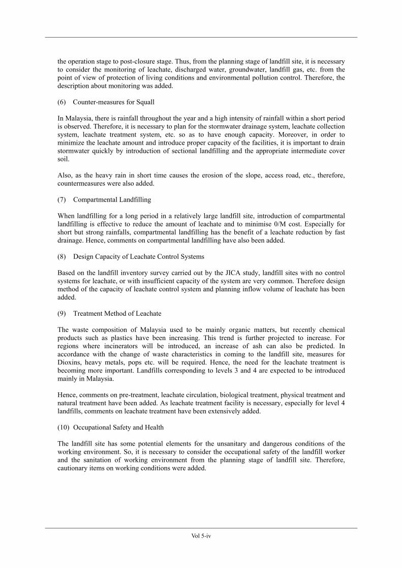
(2) Level of Sanitary Landfill
Actual site visits by the JICA study team in the year 2003 to prepare the landfill inventory and data collection from local authorities showed that there is difference in the interpretation of the sanitary landfill level by each of the team and the local authorities.
Therefore, in order to develop a unified understanding of the facility/operation levels of sanitary landfill, level 1-4, more detailed description of the concept of each level was prepared, and recommendations to develop the landfill with the higher possible level was also included.
Concretely, the additional descriptions on the concept of each sanitary landfill level are as follows.
Vol 5-iii
<Primitive level> Level 1 Primitive Landfill required for basic urban sanitation*(*waste removal from the
living environment.)
<Minimum level> Level 2 Maintain a healthy sanitary environment in and around the landfill at a minimum
level
<Basic level> Level 3 Alleviate the environmental impact of leachate by collecting and circulating the
leachate, and accelerate the stabilization of the landfill by maintaining a semi aerobic state
<Advanced level> Level 4 Control the impact of leachate to the ground water system by treating the leachate
and constructing a seepage control works.
Table Concept of Levels 1-4 of Sanitary Landfill
Item Level 1 Level 2 Level 3 Level 4
Urban sanitation +++ +++ +++ +++
Maintain a healthy sanitary environment in and around the landfill ++ +++ +++
Alleviate the environmental impact ++ +++
Acceleration of stabilization by leachate + +++ +++
Reduction of the effect to the underground water system by leachate ++ +++
The functions of the landfill site were reviewed, and three functions were clearly identified, "storage and treatment function", "environmental protection function", and "land development function". Especially, the land development function is an important subject for the landfill site in Malaysia, and hence aspects on the land development were added.
(4) Necessity of the Cover Soil
Majority of landfill sites in Malaysia have inadequate cover soil, and that is the major factor which makes the sanitary condition of the landfill inferior. The main cause of inadequacy of cover soil is that the acquisition of cover soil isn't stipulated in the development plan of the landfill site. Therefore, in order to stipulate the acquisition of the cover soil from the planning stage of landfill site, significance and technical requirement for cover soil were added to the technical guideline.
Further, regarding the calculation method for the design capacity of the landfill, the description of the method for calculating the cover soil volume was modified so as to be able to calculate the design capacity inclusive of the volume of cover soil, by adding the method for calculation of cover soil volume requirements.
(5) Environmental Monitoring
When developing a landfill site, the preliminary procedure of environment impact assessment is important, and in addition, it is important to implement the appropriate monitoring throughout from
Vol 5-iv
the operation stage to post-closure stage. Thus, from the planning stage of landfill site, it is necessary to consider the monitoring of leachate, discharged water, groundwater, landfill gas, etc. from the point of view of protection of living conditions and environmental pollution control. Therefore, the description about monitoring was added.
(6) Counter-measures for Squall
In Malaysia, there is rainfall throughout the year and a high intensity of rainfall within a short period is observed. Therefore, it is necessary to plan for the stormwater drainage system, leachate collection system, leachate treatment system, etc. so as to have enough capacity. Moreover, in order to minimize the leachate amount and introduce proper capacity of the facilities, it is important to drain stormwater quickly by introduction of sectional landfilling and the appropriate intermediate cover soil.
Also, as the heavy rain in short time causes the erosion of the slope, access road, etc., therefore, countermeasures were also added.
(7) Compartmental Landfilling
When landfilling for a long period in a relatively large landfill site, introduction of compartmental landfilling is effective to reduce the amount of leachate and to minimise 0/M cost. Especially for short but strong rainfalls, compartmental landfilling has the benefit of a leachate reduction by fast drainage. Hence, comments on compartmental landfilling have also been added.
(8) Design Capacity of Leachate Control Systems
Based on the landfill inventory survey carried out by the JICA study, landfill sites with no control systems for leachate, or with insufficient capacity of the system are very common. Therefore design method of the capacity of leachate control system and planning inflow volume of leachate has been added.
(9) Treatment Method of Leachate
The waste composition of Malaysia used to be mainly organic matters, but recently chemical products such as plastics have been increasing. This trend is further projected to increase. For regions where incinerators will be introduced, an increase of ash can also be predicted. In accordance with the change of waste characteristics in coming to the landfill site, measures for Dioxins, heavy metals, pops etc. will be required. Hence, the need for the leachate treatment is becoming more important. Landfills corresponding to levels 3 and 4 are expected to be introduced mainly in Malaysia.
Hence, comments on pre-treatment, leachate circulation, biological treatment, physical treatment and natural treatment have been added. As leachate treatment facility is necessary, especially for level 4 landfills, comments on leachate treatment have been extensively added.
(10) Occupational Safety and Health
The landfill site has some potential elements for the unsanitary and dangerous conditions of the working environment. So, it is necessary to consider the occupational safety of the landfill worker and the sanitation of working environment from the planning stage of landfill site. Therefore, cautionary items on working conditions were added.
Vol 5-v
(11) Landfill Operation and Maintenance Control
Recently, in some cases, landfill operation has been commissioned to private contractors, and this trend will be more widely introduced in the near future in Malaysia. Under this condition, government side will have the responsibility for monitoring of landfill operation under certain contract conditions. Based on this understanding, in order to carry out the proper monitoring of landfill operation, performance indicators have been added. The main indicators are as follows.
Incoming waste record Landfill works Facility and equipment Environmental protection and monitoring Social consideration
Moreover, “Part III Management of Sanitary Landfill” was newly created in this guideline.
Items for operation and management of landfill will be summarized based on the landfill operation manual in the making by Japan Waste Research Foundation (JWRF).
(12) Rehabilitation of Existing Landfill Site
Based on the landfill inventory survey carried out by the JICA study, it was found that more than 90% of landfill sites in Peninsula Malaysia are open dumping or level 1, and are therefore sources of environmental risks. Therefore, the necessity of the rehabilitation of existing landfill sites in accordance with this guideline was stated.
(13) Cost for Landfill Construction and Operation
Information on the cost for landfill site construction has been added, just for reference. It should be noted that cost is very site specific matter and therefore it depends very much on the site location, site condition, design concept etc.
(14) Explanation of Intermediate Treatment
To refine the waste management plan comprehensively by introduction of the appropriate intermediate treatment, such as recycling, incineration system, etc. is important for the effective utilization of resources and construction of a recycle-based sustainable society. It is also important for the reduction of environmental load to the landfill site, and for the early stabilization of landfill site.
Therefore, introduction on the related intermediate treatment systems such as recycling, incineration system, were added.
(15) Updating Data
Data was updated to collect the present SWM condition in Malaysia.
(16) Revision of the Contents
In addition to the comments mentioned above, the overall contents of the guideline have been modified to make it more reader friendly. Also, focused points of each article of the guideline have been put at the heading, followed by explanation.
Vol 5-vi
ABBREVIATIONS
AD Anaerobic Digestion ADCMW Annual Designed Cover Material Weight ADLV Annual Designed Landfill Volume ADLW Annual Designed Landfill Weight BOD Biochemical Oxygen Demand CAPEX Capital Expenditure CHP Combined Heat and Power CMV Cover Material Volume COD Chemical Oxygen Demand DLC Designed Landfill Capacity DO Dissolved Oxygen DOE Department of Environment EfW Energy-from-Waste EIA Environmental Impact Assessment FRP Fibreglass Reinforced Plastic GOM Government of Malaysia JICA Japan International Cooperation Agency JWRF Japan Waste Research Foundation LAs Local Authorities MSW Municipal Solid Waste MLSS Mixed Liquor Suspended Solid MRF Material Recycling Facility O & M Operation and Maintenance RDF Refuse Derived Fuel SS Suspended Solids SVI Sludge Volume Index SWCM Specific Weight of Cover Material SWM Solid Waste Management SWW Specific Weight of Solid Waste VHV Vehicle Haulage Volume
Vol 5-vii
TABLE OF CONTENTS
STRUCTURE AND CHARACTERISTICS OF THE TECHNICAL GUIDELINE FOR SANITARY LANDFILL, DESIGN AND OPERATION (Revised Draft, 2004) ··················· i
ABBREVIATIONS ···················································································································· vi
TABLE OF CONTENTS··········································································································· vii
LIST OF TABLES······················································································································ xii
LIST OF FIGURES ··················································································································· xiv
LIST OF APPENDICES············································································································ xvi
DEFINITION OF TERMS········································································································ xvii
Part I Introduction and Basic Design of Sanitary Landfill·········································· I-1
Chapter 1 Landfill Disposal Concept···················································································· I-1 1.1 Landfill Disposal Concept ···················································································· I-1 1.2 Classification of Landfill Types············································································ I-2 1.3 Decomposition and Stabilisation of Waste at the Sanitary Landfill ······················· I-4
Chapter 2 Scope of Application····························································································· I-6 2.1 Scope of Application ···························································································· I-6
Chapter 3 Planning of Sanitary Landfill System································································· I-7 3.1 Solid Wastes Management Master Plan ································································ I-7 3.2 Laws and Regulations Related to Solid Waste Management································· I-7 3.3 SWM Intermediate Treatment ·············································································· I-8 3.4 Formulation of The Implementation Plan ····························································· I-8 3.5 Basic Design Parameters ······················································································ I-11
3.5.1 Target Lifespan / Target Year ································································ I-11 3.5.2 Designed Landfill Capacity ·································································· I-11 3.5.3 Designed Composition of Solid Waste in Sanitary Landfill ·················· I-15
Chapter 4 Formulation of Sanitary Landfill System··························································· I-17 4.1 Functions of Sanitary Landfill System·································································· I-17
4.2 Determination of Site Location············································································· I-21 4.2.1 Site Selection························································································ I-21 4.2.2 Survey of Present Conditions································································ I-23
4.4 Management of Sanitary Landfill System····························································· I-26
Vol 5-viii
4.5 Performance Indicators for the Landfill Management/Control······························ I-27 4.6 Post Closure Land-use Plan·················································································· I-28 4.7 Other Considerations···························································································· I-28
4.7.1 Compliance to Other Guidelines and Standards ···································· I-28 4.7.2 Occupational Health and Safety···························································· I-29 4.7.3 Weather Conditions ·············································································· I-30 4.8 Rehabilitation of Waste Landfill Site ···················································· I-31
Part II Technical Guideline on Sanitary Landfill System ············································· II-1
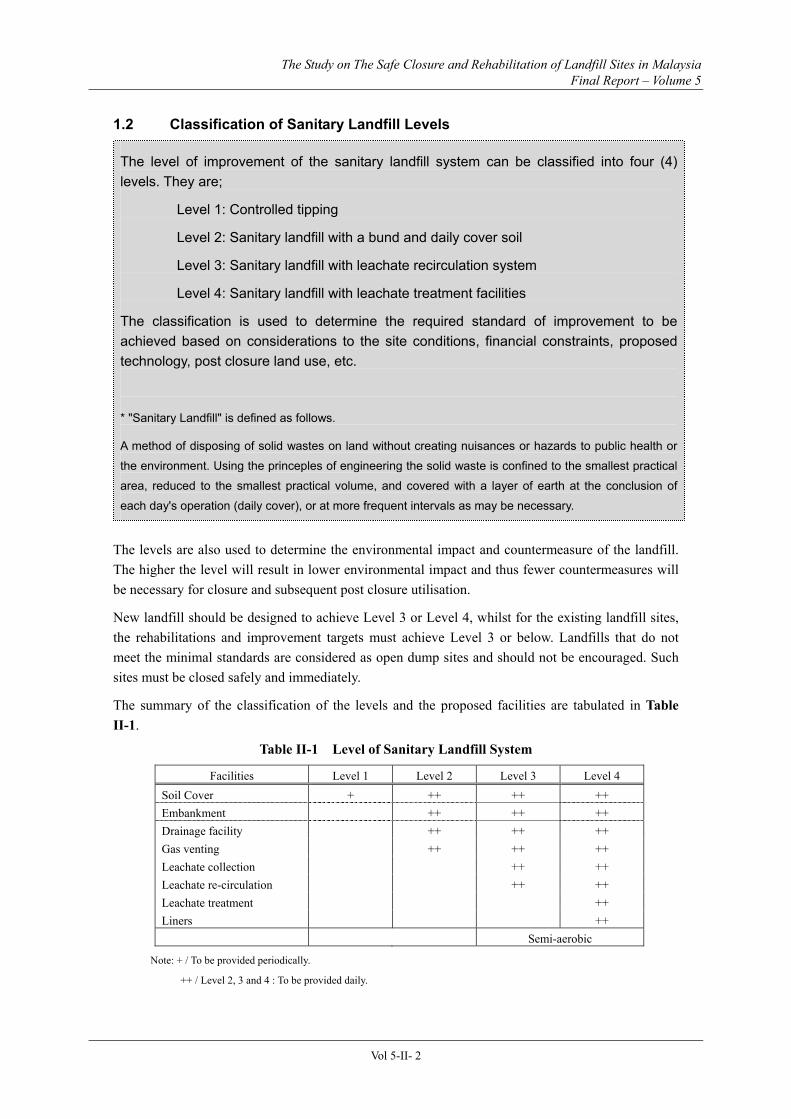
Chapter 1 General ·················································································································· II-1 1.1 Integrated Landfill Facilities ················································································ II-1 1.2 Classification of Sanitary Landfill Levels····························································· II-2
Chapter 2 Waste Retaining Facility ······················································································ II-7 2.1 Functions of Waste Retaining Facility ·································································· II-7 2.2 Planning and Design Concepts ············································································· II-7 2.3 Selection of Waste Retaining Facility and Structural Configuration ····················· II-9 2.4 Loading on Waste Retaining Facility ···································································· II-10 2.5 Corrosion Control································································································· II-11
Chapter 3 Stormwater Drainage Facility ············································································· II-13 3.1 Functions of Stormwater Drainage Facility ·························································· II-13 3.2 Types of Stormwater Drainage Facility ································································ II-13 3.3 Planning and Design of Stormwater Drainage Facility ········································· II-16
Chapter 4 Leachate Collection Facility ················································································ II-20 4.1 Functions of Leachate Collection Facility ···························································· II-20 4.2 Components of Leachate Collection Facility ························································ II-20 4.3 General Structure of Leachate Collection Facility ················································ II-22 4.4 Design Flow and Cross Sectional Area································································· II-26 4.5 Loading Conditions ······························································································ II-27 4.6 Other Aspects in Planning ···················································································· II-28
Chapter 5 Liner Facility········································································································· II-29 5.1 Functions of Liner Facility ··················································································· II-29 5.2 Types of Liner Facility ························································································· II-29 5.3 Structural Characteristics and Construction of Liner Facility································ II-32 5.4 Underground Water Drainage Facility ·································································· II-38
Chapter 6 Gas Venting Facility ····························································································· II-41 6.1 Necessity of Gas Venting Facility at Landfill Site ················································ II-41 6.2 Planning and Design Concepts ············································································· II-43
7.1.1 Functions of Leachate Treatment Facility ············································· II-50 7.1.2 Planning and Designing Leachate Treatment Facility ··························· II-51 7.1.3 Components of Leachate Treatment System ········································· II-52 7.1.4 Concepts of the Operation and Maintenance········································· II-52
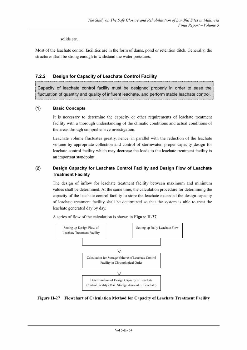
7.2 Design for Capacity of Leachate Controlling and Treatment Facilities ················· II-53 7.2.1 Leachate Control Facility/Leachate Retention Ditch····························· II-53 7.2.2 Design for Capacity of Leachate Control Facility ································· II-54 7.2.3 Calculation of Leachate Generation······················································ II-55
7.3 Design for Raw and Treated Leachate Quality ····················································· II-59 7.3.1 Design for Raw Leachate Quality ························································· II-59 7.3.2 Design for Treated Leachate Quality ···················································· II-63
7.4 Methods for Leachate Treatment ·········································································· II-64 7.4.1 Basic Concept······················································································· II-64 7.4.2 Treatment Method for Removal of Specific Parameters························ II-68 7.4.3 Outline for Each Treatment Method······················································ II-71
7.5 Operation and Maintenance for Leachate Treatment Facility································ II-79
Chapter 8 The Landfilling Process ······················································································· II-83 8.1 General················································································································· II-83 8.2 Methods of Landfilling························································································· II-84 8.3 Section Landfilling······························································································· II-91 8.4 Working Face ······································································································· II-92 8.5 Construction of Landfill Slopes············································································ II-92 8.6 Cover Soil ············································································································ II-95 8.7 Landfill Equipment ······························································································ II-101
Chapter 9 Landfill Control Facilities···················································································· II-104 9.1 Types of Control Facilities ··················································································· II-104 9.2 Waste Inspection and Measurement······································································ II-105 9.3 Monitoring ··········································································································· II-107
9.3.1 Function of Monitoring········································································· II-107 9.4 Site Office ············································································································ II-112 9.5 Safety Measures ··································································································· II-114
Chapter 10 Other Related Facilities ······················································································· II-115 10.1 Composition of Other Related Facilities······························································· II-115 10.2 Access Roads ······································································································· II-116 10.3 Littering Prevention Facility················································································· II-119 10.4 Notice Boards, Fencing, Gates and Security························································· II-119 10.5 Fire Prevention Facility ························································································ II-120 10.6 Disaster Prevention Facility·················································································· II-120
Chapter 11 Capital Costs for Construction of New Landfill Sites ······································· II-122 11.1 Basis for Estimation ····························································································· II-122 11.2 Cost Estimation ···································································································· II-123
Vol 5-x
Part III Management of Sanitary Landfill ······································································· III-1
Chapter 1 General ·················································································································· III-1 1.1 Management of the Sanitary Landfill Site ···························································· III-1
Chapter 2 Inspection of the Incoming Wastes······································································ III-2 2.1 Necessity for Inspection of the Incoming Wastes·················································· III-2 2.2 Items for Inspection······························································································ III-2 2.3 Investigation of Wastes Type and Composition ···················································· III-2 2.4 Inspection Procedures··························································································· III-3
Chapter 3 Management of The Facilities ············································································· III-4 3.1 Necessity of Management of the Facilities ··························································· III-4 3.2 Solid Waste Retaining Structures·········································································· III-4
3.2.1 Management of Solid Waste Retaining Structures ································ III-4 3.2.2 Inspection and Repair of Mound··························································· III-5 3.2.3 Inspection and Repair of Concrete Mound and
3.6.1 Management of Lining Facility····························································· III-11 3.6.2 Methods for Inspection and Repair of Liner Sheet································ III-12 3.6.3 Measure of Inspection and Repair of Earth Lining Facility··················· III-13 3.6.4 Measure of Inspection and Repair of Paths and Road Surfaces············· III-14
Chapter 4 Management of the Landfilling Activities ·························································· III-20 4.1 Necessity of Management of the Landfilling Activities ········································ III-20 4.2 Management of Landfilling Activities ·································································· III-20 4.3 Performance Management···················································································· III-21 4.4 Safety Management······························································································ III-21 4.5 Management of Information on Landfilling·························································· III-21
Chapter 5 Environmental Management ··············································································· III-22 5.1 Necessity for Environmental Management ··························································· III-22 5.2 Leachate Control ·································································································· III-22 5.3 Monitoring of the Effluent···················································································· III-23 5.4 Monitoring of the Landfill Gas············································································· III-23 5.5 Prevention of Water Pollution··············································································· III-24 5.6 Prevention of Offensive Odour············································································· III-25 5.7 Prevention of Noise and Vibrations ······································································ III-26 5.8 Management of Prevention of Breeding of Vectors and Animals ·························· III-26
Vol 5-xi
5.9 Prevention of Littering of Wastes ········································································· III-26
Chapter 6 Management of Post Closure Landfill Site························································· III-27 6.1 Necessity of Management of Post Closure Landfill Site ······································· III-27 6.2 Leachate Control ·································································································· III-27 6.3 Control of Generated Gas····················································································· III-27 6.4 Control of Land Subsidence ················································································· III-27 6.5 Monitoring of the Degradation and Stabilisation of the Waste ······························ III-27 6.6 Utilization and Management of Post Closure Landfill Site ··································· III-28
Chapter 7 Management of Information and Administrative Structure····························· III-29 7.1 Management of Information ················································································· III-29 7.2 Administrative Structure······················································································· III-29
Part IV Appendices ············································································································ IV-1
Appendix 1 Master Plans for Solid Waste Disposal ······························································· IV-1
Appendix 3 Example of Design Calculation for Leachate Treatment and Controlling Facility ······························································································ IV-9
3.1 Example Calculation 1 ························································································· IV-9 3.2 Example Calculation 2: Example of Calculation for Scales of Leachate Treatment and
Leachate Control Facilities by Rational Formula(Technical Guideline on Sanitary Landfill -Planning and Designing- (Japan, 2001))·············································· IV-10
Table I-2 Typical Specific Gravity of Waste ................................................................................12
Table I-3 Estimated Solid Waste Generated in Malaysia ...........................................................14
Table I-4 Typical Specific Weight of Landfill Waste...................................................................14
Table I-5 Composition of Solid Waste (% wt, Wet Basis) in Kuala Lumpur (2002) ................15
Table I-6 Composition of Solid Waste (% wt, Dry Basis) in Kuala Lumpur (2002) ................16
Table I-7 The Relationship between the Functions and the Facilities in the Landfill..............21
Table I-8 Performance Indicators for the Landfill Management/Control ................................27
<Part II>
Table II-1 Level of Sanitary Landfill System.................................................................................2
Table II-2 Design Examples of Waste Retaining Facility in Japan............................................11
Table II-3 Corrosion Rate of Steel ................................................................................................12
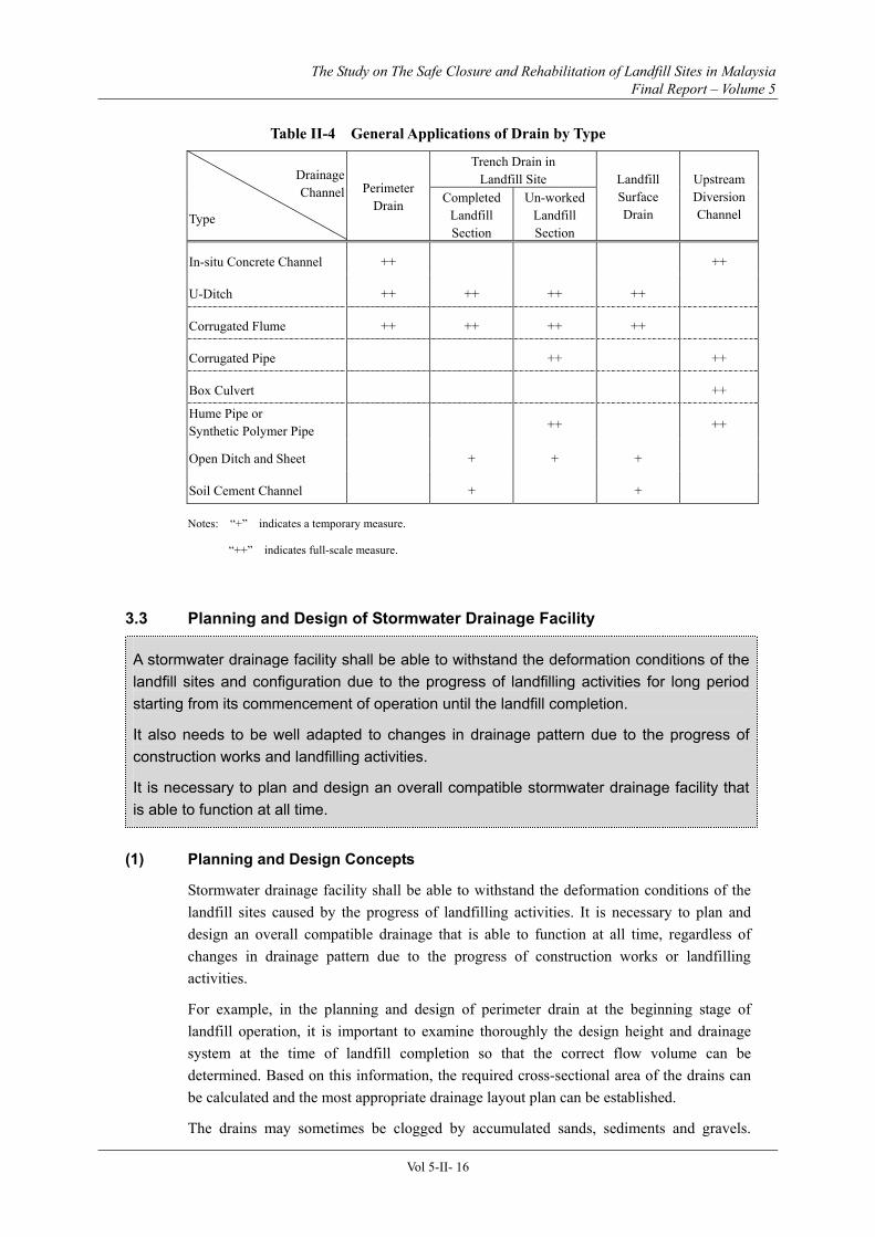
Table II-4 General Applications of Drain by Type......................................................................16
Table II-5 Coefficient of Peak Flow by Landform ......................................................................18
Table II-6 Coefficient of Peak Flow by Land-use Development.................................................18
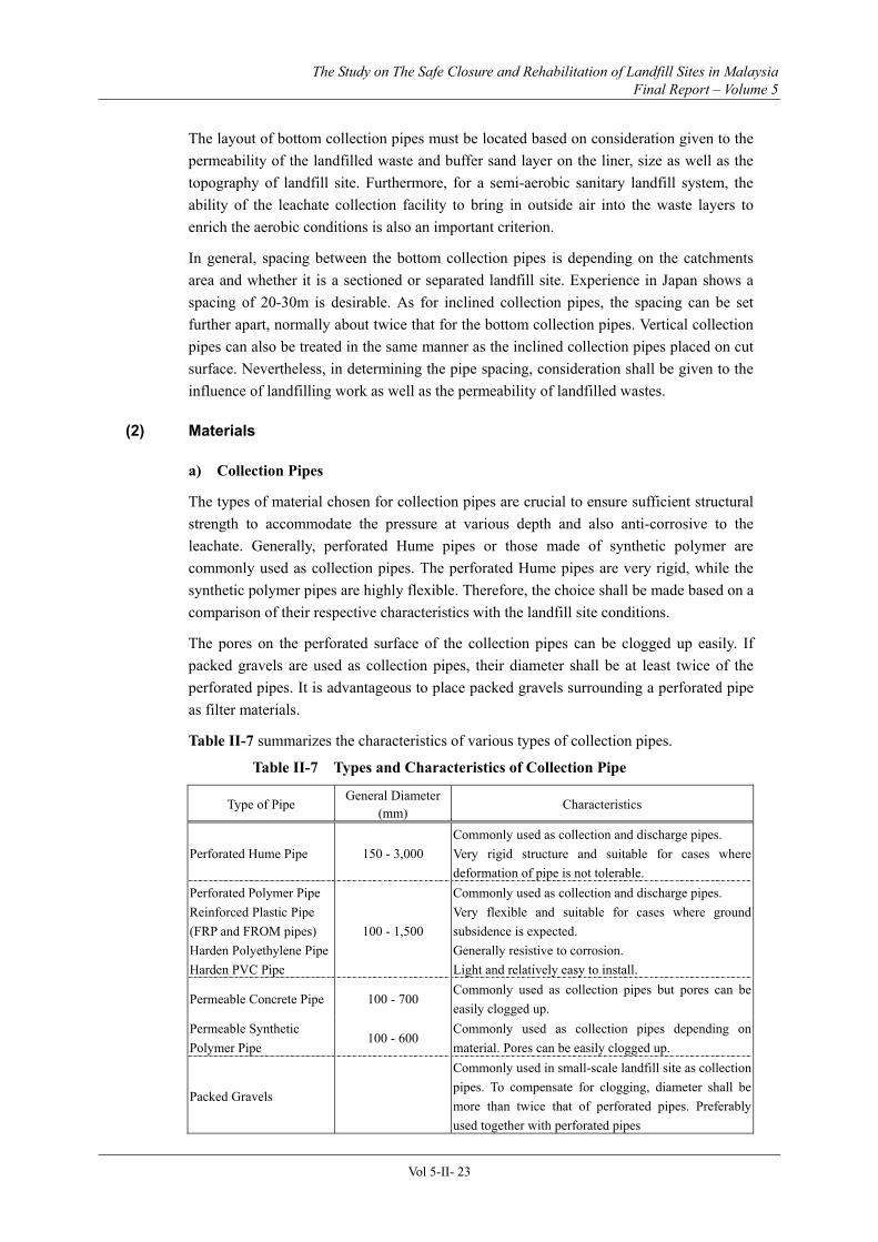
Table II-7 Types and Characteristics of Collection Pipe ............................................................23
Table II-8 Comparison between Surface and Vertical Liner Facility........................................31
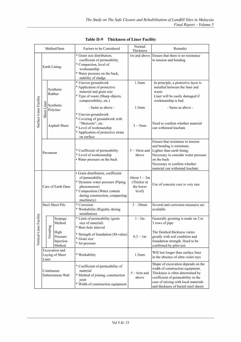
Table II-9 Thickness of Liner Facility ..........................................................................................33
Table II-10 Causes of Damage to Liner Facility..........................................................................36
Table II-11 Protection for Liner Facility (Liner sheets)..............................................................37
Table II-12 Influence of Hydrogen Sulphide to Human Body ...................................................42
Table II-13 Leachate Parameters for Planning a Leachate Treatment Facility .......................60
Table II-14 Variation of Raw Leachate Quality with Different Waste Types (Survey of 59 Locations in Japan)...................................................................................................................63
Table II-15 Guidelines for Raw Leachate Quality in Semi-Aerobic Landfill Type ..................63
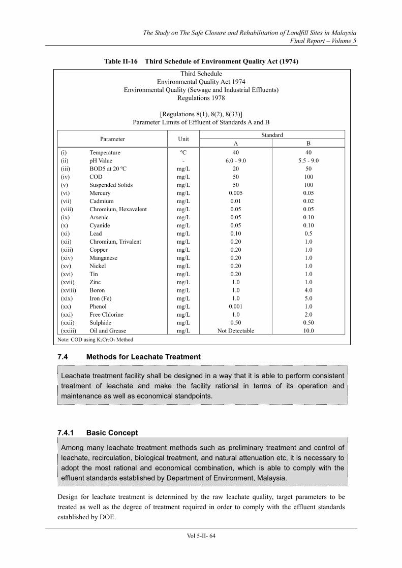
Table II-16 Third Schedule of Environment Quality Act (1974) ...............................................64
Table II-17 Relation between Landfilled Wastes and Targets of Leachate Treatment ............65
Table II-18 The General Methods for Treatment of Specific Parameters.................................69
Table II-19 BOD Removal and Treatment Method.....................................................................69
Vol 5-xiii
Table II-20 COD and Colour Removal and Treatment Method ................................................70
Table II-21 Heavy Metal Removal and Treatment Method .......................................................70
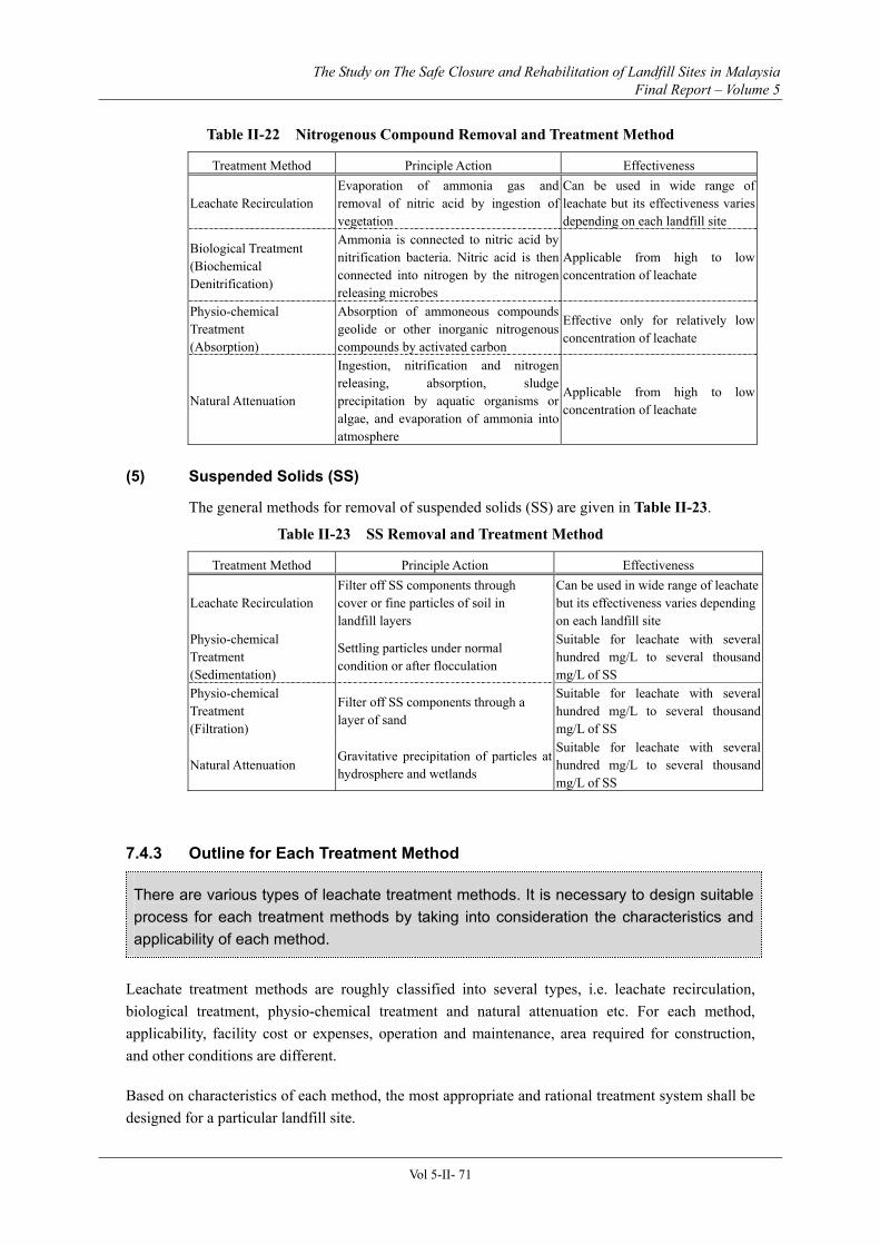
Table II-22 Nitrogenous Compound Removal and Treatment Method.....................................71
Table II-23 SS Removal and Treatment Method.........................................................................71
Table II-24 Relationships between Landfilling Process and the Objectives .............................84
Table II-25 Average Working Face Required for Landfill Sites ................................................92
Table II-26 Unified Soil Classification System And Characteristics..........................................99
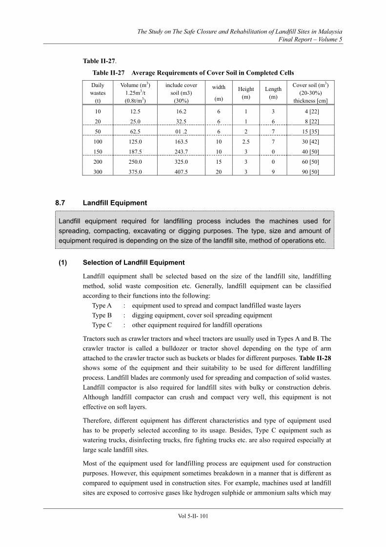
Table II-27 Average Requirements of Cover Soil in Completed Cells.....................................101
Table II-28 Comparison of Equipment for Landfilling Works ................................................102
Table II-29 Average Equipment Requirements for a Sanitary Landfill..................................103
Table II-30 Example of Input Information for Automatic Weighing System .........................107
Table II-31 Example of Monitoring Items and Frequency.......................................................108
Table II-32 Monitoring of Gas Generation ................................................................................ 111
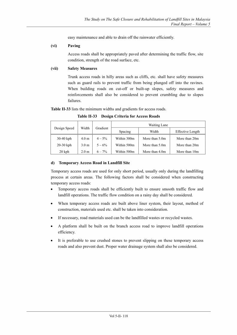
Table II-33 Design Criteria for Access Roads............................................................................118
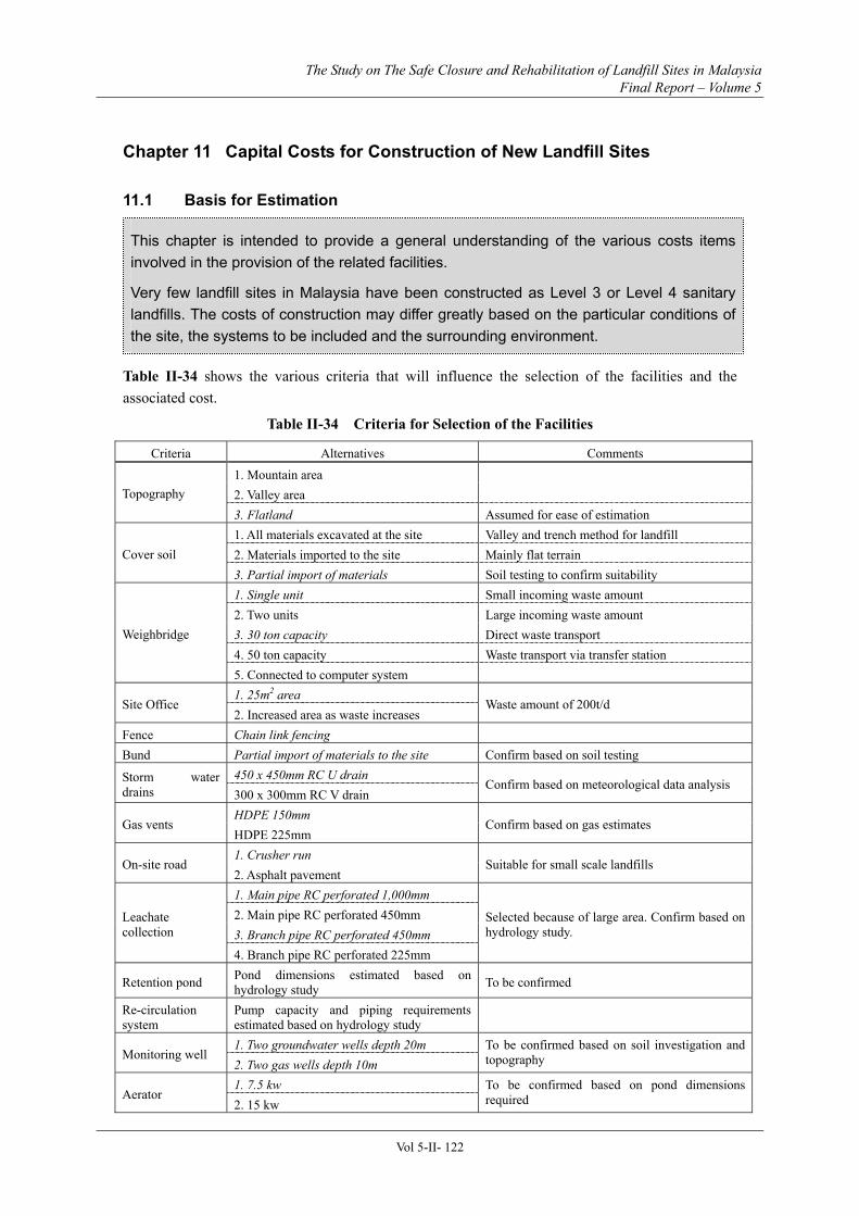
Table II-34 Criteria for Selection of the Facilities.....................................................................122
Table II-35 Summary of CAPEX for Sanitary Landfill ...........................................................123
Table IV-3-2 Results of Computation [Calculation]....................................................................13
Vol 5-xiv
LIST OF FIGURES
<Part I>
Figure I-1(a) Recirculatory Semi-aerobic Landfill Type ..............................................................2
Figure I-1(b) Classification of Landfill Type .................................................................................3
Figure I-2 Stabilization Mechanism of Sanitary Landfill System................................................5
Figure I-3(a) Implementation Plan for Sanitary Landfill System and its Inter-relationship with Other Processes...................................................................................................................9
Figure I-3(b) Example of Flowchart for The Implementation Plan ..........................................10
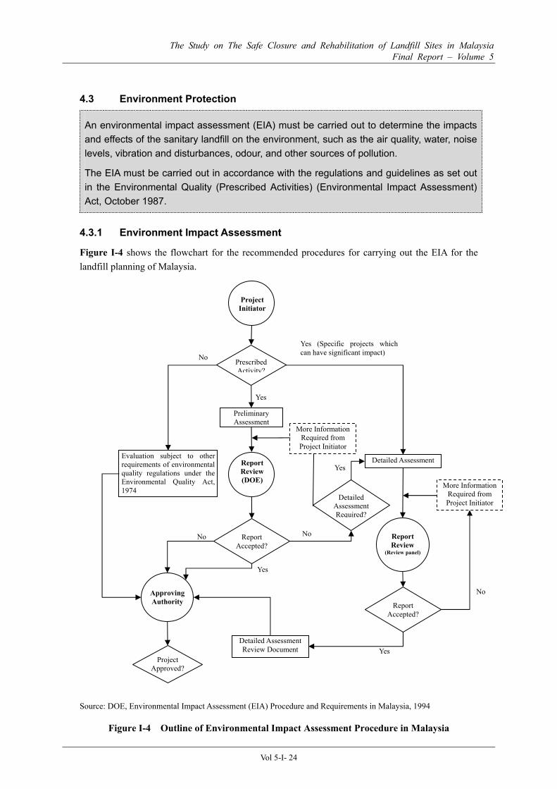
Figure I-4 Outline of Environmental Impact Assessment Procedure in Malaysia ...................24
Figure II-2(a) Typical Layout for the Level 2 Sanitary Landfill..................................................6
Figure II-2(b) Typical Layout for the Level 3 Sanitary Landfill .................................................6
Figure II-2(c) Typical Layout for the Level 4 Sanitary Landfill..................................................6
Figure II-3 Design Procedure of Waste Retaining Facility...........................................................9
Figure II-4 Enclosing Bund for Landfilled Waste Retaining Facility .......................................10
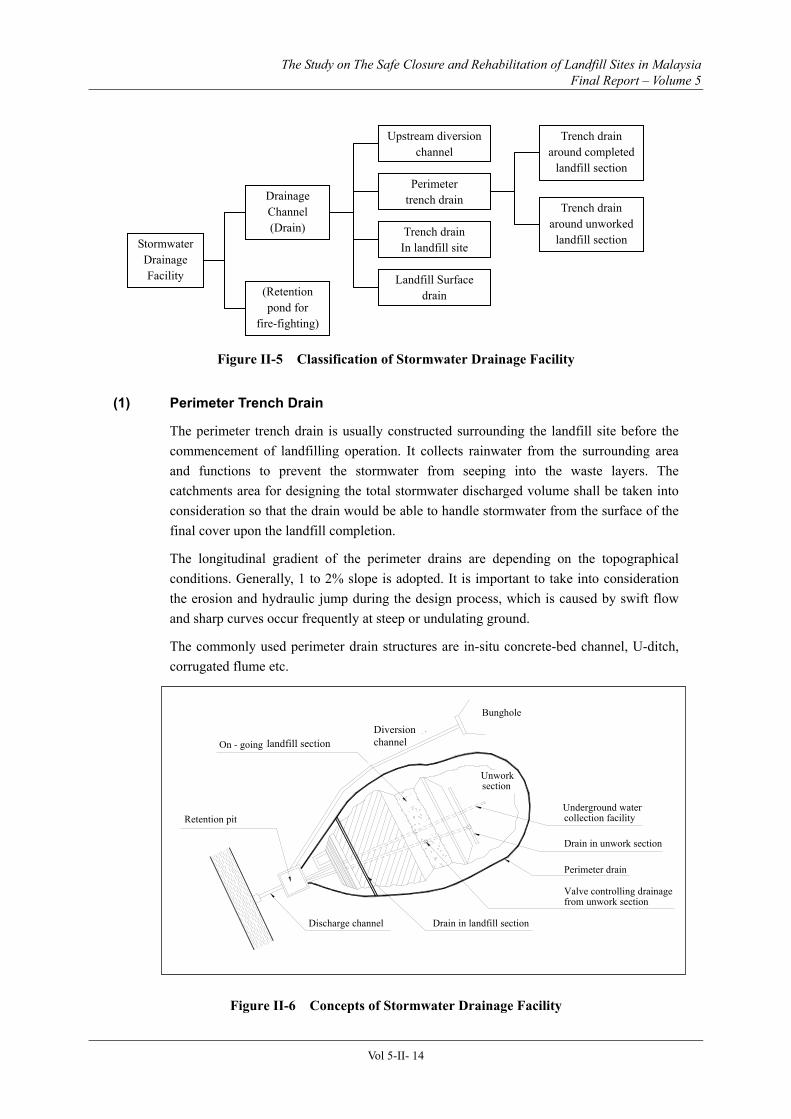
Figure II-5 Classification of Stormwater Drainage Facility.......................................................14
Figure II-6 Concepts of Stormwater Drainage Facility ..............................................................14
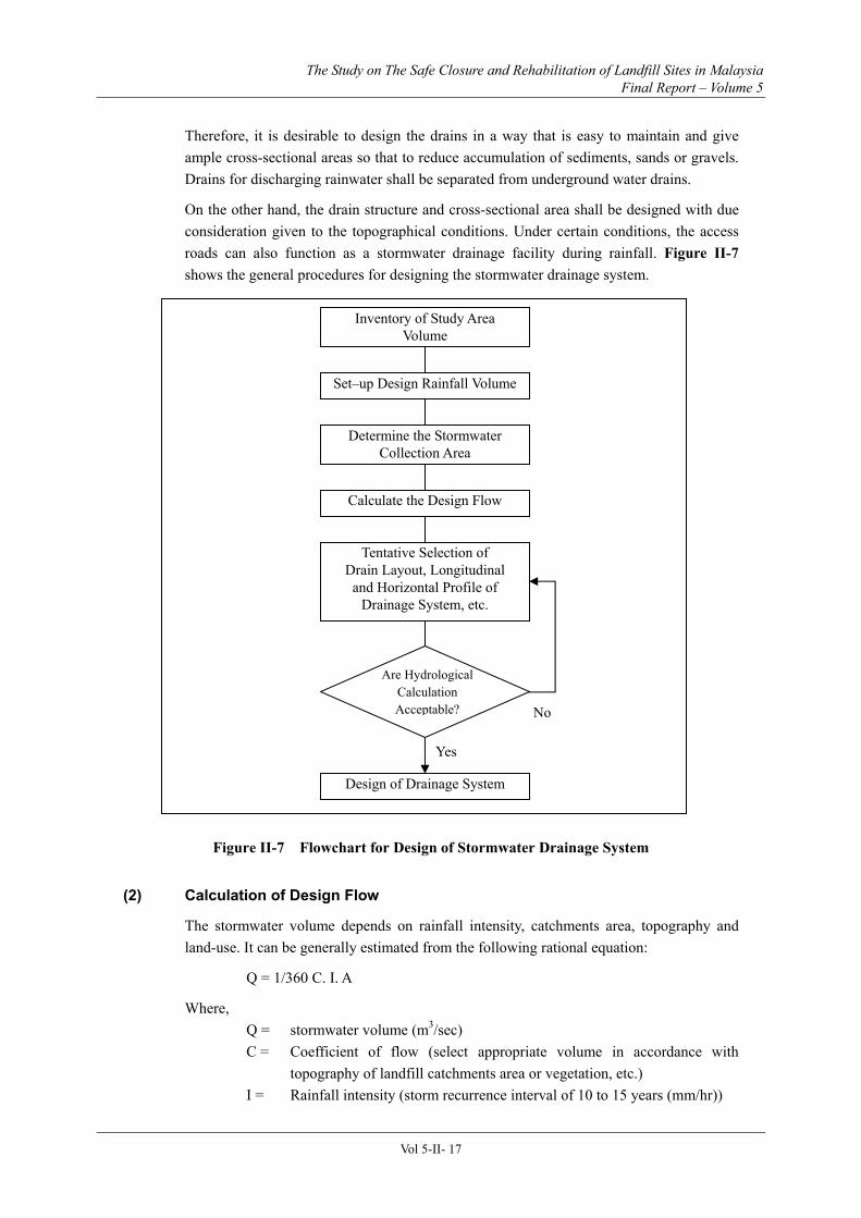
Figure II-7 Flowchart for Design of Stormwater Drainage System...........................................17
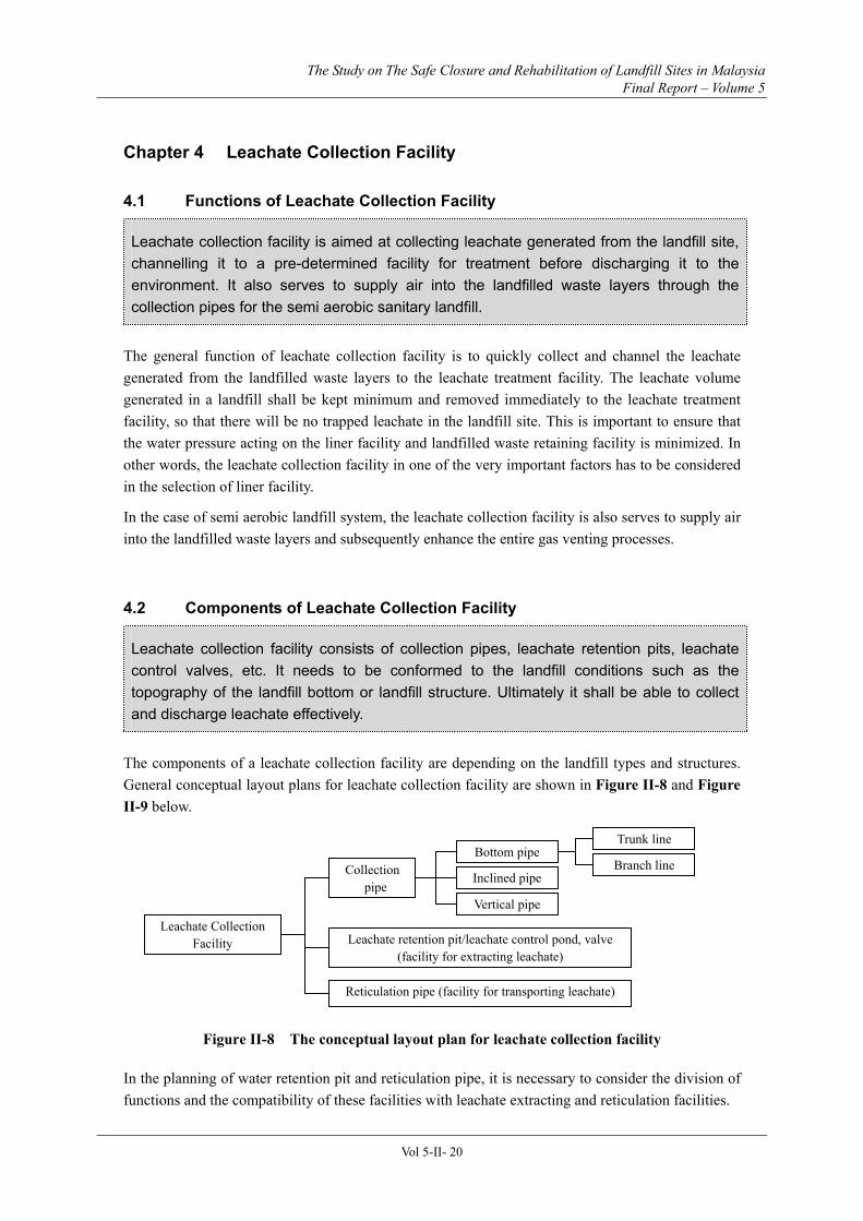
Figure II-8 The conceptual layout plan for leachate collection facility.....................................20
Figure II-9 Concept of Leachate Collection Facility...................................................................21
Figure II-10 Layout Plans for Bottom Pipe .................................................................................22
Figure II-11 Typical Design of Bottom Pipe.................................................................................25
Figure II-12 Example of Vertical Pipe..........................................................................................26
Figure II-13 Concepts of Liner Facility........................................................................................30
Figure II-14 Installation of Gas Vent in Landfill with Liner Facility........................................35
Figure II-15 Cross Section of Underground Water Drainage Facility ......................................39
Figure II-16 Explosive and Combustion Limits of Methane Gas and Air Mixture at 20ºC and Atmospheric Pressure...............................................................................................................42
Figure II-17 Fluctuation of Gas Composition in Landfill By Time ...........................................43
Figure II-18 Classification of Gas Venting Facility .....................................................................44
Vol 5-xv
Figure II-19 Flow of Gas Produced in Landfill ...........................................................................45
Figure II-20 Example of Vertical Gas Vent..................................................................................46
Figure II-21 Example of Inclined Gas Vent .................................................................................46
Figure II-22 Examples of Intervals for Gas Vents.......................................................................47
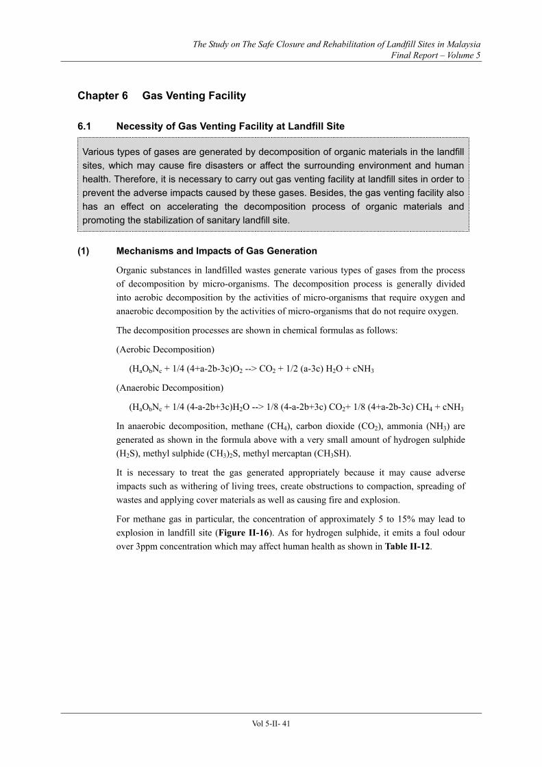
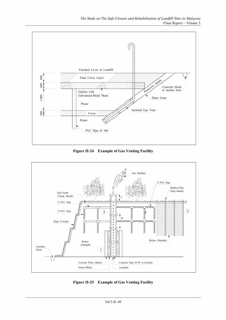
Figure II-23 Example of Gas Venting Facility .............................................................................48
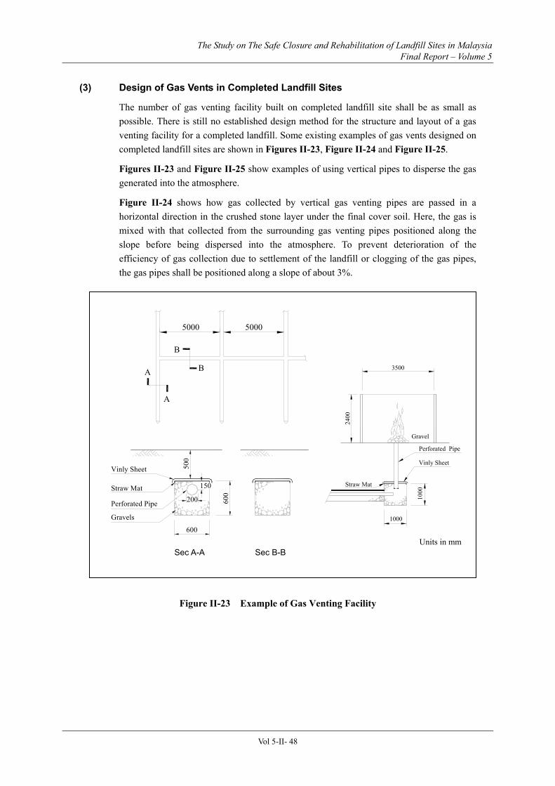
Figure II-24 Example of Gas Venting Facility .............................................................................49
Figure II-25 Example of Gas Venting Facility .............................................................................49
Figure II-26 Components of Leachate Treatment System..........................................................52
Figure II-27 Flowchart of Calculation Method for Capacity of Leachate Treatment Facility54
Figure II-28 Water Flows Balance Model for Landfill Site........................................................55
Figure II-29 Fluctuation of BOD According to Different Types of Landfill System ................61
Figure II-30 Fluctuation of NH4+-N According to Different Types of Landfill System............61
Figure II-31 Fluctuation of BOD, COD and NH4+-N, (Calculation Model)..............................62
Figure II-32(a) Combination of Recirculation Process for Leachate Treatment (Recirculation + Bio-treatment + Physio-chemical treatment) .............................................66
Figure II-32(b) Combination of Recirculation Process for Leachate Treatment (Recirculation + Bio-treatment + Physio-chemical treatment) .............................................66
Figure II-32 (c) Combination of Recirculation Process for Leachate Treatment (Recirculation + Natural Attenuation) ....................................................................................66
Figure II-32 (d) Combination of Recirculation Process for Leachate Treatment (Recirculation + Natural Attenuation + Physio-chemical treatment)...................................66
Figure II-33 Example of Recirculation Semi-aerobic Landfill System .....................................67
Figure II-34 Example of Flow Diagram for Typical Oxidation Process....................................68
Figure II-35 Fluctuation of Molecular Weight With Landfilling Schedule...............................80
Figure II-36 Composition of Landfilling Process ...........................................................................83
Figure II-37 Area Method .............................................................................................................85
Figure II-38 Progressive Slope or Ramp Method........................................................................86
Figure II-48 Pushing Up and Compacting the Wastes Simultaneously.....................................90
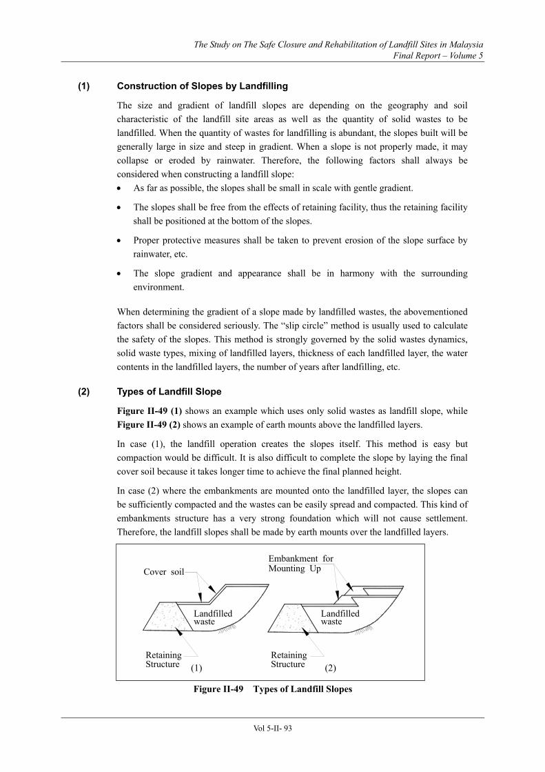
Figure II-49 Types of Landfill Slopes ...........................................................................................93
Figure II-50 Example of the Structure of Slopes and Earth Bunds...........................................94
Figure II-51 Textural Classification Chart (U.S. Department of Agriculture) and Comparison of Particle Size Wastes ..............................................................................................................98
Figure II-52 Checklist of Items to be Controlled at a Landfill Site .........................................104
Figure II-53 Structure of Control Facilities ...............................................................................104
Figure II-54 Structure of Weighbridge.......................................................................................106
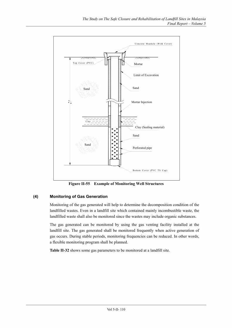
Figure II-55 Example of Monitoring Well Structures...............................................................110
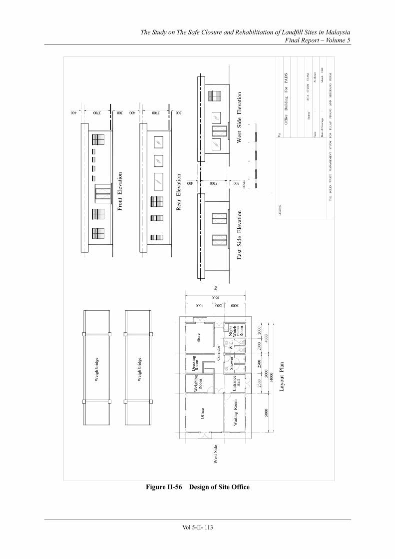
Figure II-56 Design of Site Office ...............................................................................................113
Figure II-57 Layout of Related Facilities at a Landfill Site......................................................115
Figure II-59 Typical Design for Installation of Fence ...............................................................119
<Part IV>
Figure IV-3-1 Cross Section of Sanitary Landfill in Mountain Areas .......................................10
Figure IV-3-2 Flow Diagram for Calculation for Water Balance of Capacity of Leachate Control Facility .........................................................................................................................13
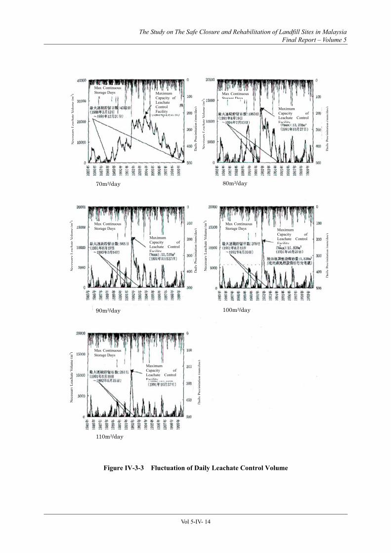
Figure IV-3-3 Fluctuation of Daily Leachate Control Volume...................................................14
LIST OF APPENDICES
Appendix 1 Master Plans for Solid Waste Disposal ······························································· IV-1
Landfill site: The site where municipal wastes are disposed off by land filling. Such sites may be provided with various landfill facilities. In accordance with the “Technical Guideline for Sanitary Landfill, Design and Operation (Revised draft, 2004)”, the landfill sites can be categorised into 4 types; i.e. from Level 1 (L1) to Level 4 (L4). Open Dumpsite is categorised as Level Zero (L0.)
Closed landfill site: The landfill site where the waste filling activities have been completed.
Abandoned site: The landfill site where the owners/operators could not be identified. “Illegal dump site” will be included in this category.
Safe closure (SC): “Safe closure” consists of the activities of “Physical closure (PC)” and “Post-closure management (PCM)”.
Physical closure (PC): The action by which the necessary measures for safe closure has been applied to the entire landfill area.
Closure levels (C1, C2, C3, C4): There are 4 closure levels, i.e. from C1 to C4. These closure levels indicate the countermeasures necessary to control the environmental pollution and hazards from the landfill sites. Each landfill site should be assigned with a targeted closure level at the initial stages of the safe closure process.
Post-closure management (PCM): The management activities necessary to operate, maintain and monitor the landfill facilities such as the leachate treatment, landfill gas treatment, cover soil etc. The activities also include the environmental monitoring, landfill stabilization monitoring and management of information/ records of the closed landfills.
Post-closure land use: The re-utilization of closed landfill sites for purposes other than for waste filling. The PCM activities should be continued through out the post-closure land use.
Part I
Introduction and Basic Design of Sanitary Landfill
The Study on The Safe Closure and Rehabilitation of Landfill Sites in Malaysia Final Report – Volume 5
Vol 5-I- 1
Part I Introduction and Basic Design of Sanitary Landfill
Chapter 1 Landfill Disposal Concept
1.1 Landfill Disposal Concept
The aim of solid waste disposal is to immediately remove discarded waste from the community by reducing its volume and rendering them stable and hygienic.
In selecting the proper treatment and disposal process, consideration must be given to the geographical area, the financial situation and the level of technology to be used. Generally, such solid waste management (SWM) process can be divided into three activities such as collection/transport, intermediate treatment and final disposal. Disposal by landfilling is the only final disposal method that treats and restores the organic portions of the waste back to nature.
It is important to have a practical method of disposal that takes into account of the type, form and composition of wastes, the location of disposal site, the local environment, geology, ecology, hydrology and climatic conditions.
In planning the final disposal site, it is necessary to determine and establish the types and volume of waste for landfilling in order to formulate an effective master plan for solid waste management based on the actual needs of the region. This final disposal plan should take into account and be integrated with the other collection or haulage plans and intermediate treatment plan.
Solid waste management (SWM) can be defined as the systematic interaction between various activities of waste generation, storage, collection, transfer and transport, intermediate treatment and final disposal. Newer concepts such as resource recovery, volume reductions, solid wastes stabilisation or sanitation have been incorporated in the SWM processes. Although more advanced and sophisticated intermediate treatment methods have been developed, the sanitary landfilling method is still considered to be one of the most important and ideal final disposal process.
The primary aim of ideal final disposal method is to adopt the sanitary and environmental friendly landfilling method. Other advanced concept of technology may also be integrated, such as effective post closure utilisation, adoption of resource recovery and recycling philosophies, etc.
For effective post closure utilisation of the landfill site, it is essential to adopt the more advanced landfill management methods with semi-aerobic structure and equipped with higher level treatment facilities so that earlier stabilization of wastes may be achieved.
Final disposal sites such as sanitary landfills must be utilized with consideration towards a sustainable environment and with regards to effective utilization of available resources. In providing such landfills, the use of recycled construction material such as those reclaimed from construction and demolition wastes like concrete debris or spent activated carbon, or biomass material should be encouraged.
The Study on The Safe Closure and Rehabilitation of Landfill Sites in Malaysia Final Report – Volume 5
Vol 5-I- 2
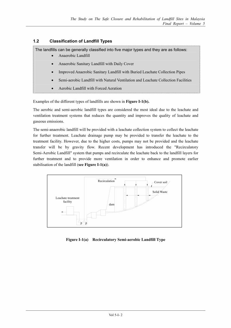
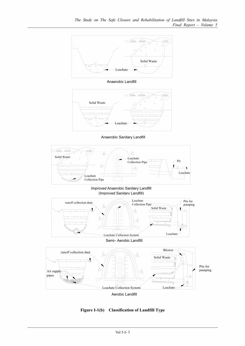
1.2 Classification of Landfill Types
The landfills can be generally classified into five major types and they are as follows: • Anaerobic Landfill
• Anaerobic Sanitary Landfill with Daily Cover
• Improved Anaerobic Sanitary Landfill with Buried Leachate Collection Pipes
• Semi-aerobic Landfill with Natural Ventilation and Leachate Collection Facilities
• Aerobic Landfill with Forced Aeration
Examples of the different types of landfills are shown in Figure I-1(b).
The aerobic and semi-aerobic landfill types are considered the most ideal due to the leachate and ventilation treatment systems that reduces the quantity and improves the quality of leachate and gaseous emissions.
The semi-anaerobic landfill will be provided with a leachate collection system to collect the leachate for further treatment. Leachate drainage pump may be provided to transfer the leachate to the treatment facility. However, due to the higher costs, pumps may not be provided and the leachate transfer will be by gravity flow. Recent development has introduced the "Recirculatory Semi-Aerobic Landfill" system that pumps and recirculate the leachate back to the landfill layers for further treatment and to provide more ventilation in order to enhance and promote earlier stabilisation of the landfill (see Figure I-1(a)).
Figure I-1(a) Recirculatory Semi-aerobic Landfill Type
Leachate treatment facility
Recirculation Cover soil
Solid Waste
dam
p p
The Study on The Safe Closure and Rehabilitation of Landfill Sites in Malaysia Final Report – Volume 5
The Study on The Safe Closure and Rehabilitation of Landfill Sites in Malaysia Final Report – Volume 5
Vol 5-I- 4
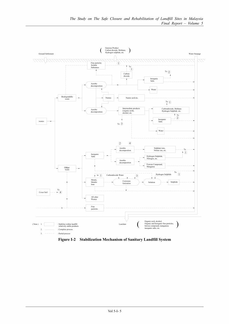
1.3 Decomposition and Stabilisation of Waste at the Sanitary Landfill
The biological, physical and chemical changes occurring between layers of landfill play important roles in the process of transformation and stabilisation of the waste. Household or municipal wastes tend to contain more organic putrescible material which are more susceptible to bacterial decomposition and hasten the stabilisation period.
Generally the solid waste doing into the landfill can be divided into two categories, i.e. Degradable and Non-Degradable wastes. The degradable waste can further be divided into biologically degradable (or biodegradable) and non-biodegradable.
(1) Degradable Waste
The degradable wastes are wastes that can be transformed either by chemical or biological processes, i.e. by corrosion or by decomposition. Such waste can be sub-divided into biodegradable and non-biodegradable waste.
The stabilisation mechanism of sanitary landfill system is shown in Figure I-2.
a) Biodegradable Waste
Biodegradable solid waste includes all organic matters such as meat, vegetables and plants waste that can be decomposed by biological digestion and fermentation. The decomposition process, with the aide of micro-organisms, breakdown the higher molecular compounds like carbohydrates and protein into lower molecular compounds such as sugar, organic acids, alcohols, etc, which will then be fermented to form carbon dioxide, methane, inorganic salts and water. The decomposition process results in the volume reduction and achieves stabilisation of the waste.
The rate of decomposition depends mainly on the type of waste and the condition of the environment. Soft less fibrous waste such as kitchen waste will decompose faster then fibrous waste such as wood or paper. Wet and warm environment will also hasten the decomposition process by promoting bacterial growth.
b) Non-biodegradable Waste
The non-biodegradable waste can also be considered as chemical-degradable waste, i.e. waste that can degrade by undergoing the processes of corrosion, ionic exchanges and liquefaction, due to chemical reactions and oxidations. Such matter includes all types of metals and some inorganic salts. The metals coming in contact with the water or acid present in the waste layers will oxidise to form rust or other forms of metallic oxides, which will eventually breakdown further to the ionic compound, and react with other chemicals to form gasses and salts. The combustion process, i.e. by incineration, paralysis, gasification etc. is also form of chemical transformation processes.
(2) Non-Degradable Waste
The non-degradable wastes are wastes that will not degrade naturally and requires transformation by physical processes, i.e. waste such as concrete, rocks, majority of the plastics, glass etc. The reduction in volume and size can only be achieved by shredding, grinding and compression.
The Study on The Safe Closure and Rehabilitation of Landfill Sites in Malaysia Final Report – Volume 5
Vol 5-I- 5
Figure I-2 Stabilization Mechanism of Sanitary Landfill System
( )Organic acid, alcohol,Organic and Inorganic fine particles,ferrous compound, manganese inorganic salts, etc.
Leachate( Note ) 1. : Stabilize within landfillrelatively stable products
2. : Complete process
3. : Partial process
1To
12To
To 1
2To
3To
2 4
1
Hydrogen Sulphide 1To
3to 1 Carbondioxide Water
4To
Other
The Study on The Safe Closure and Rehabilitation of Landfill Sites in Malaysia Final Report – Volume 5
Vol 5-I- 6
Chapter 2 Scope of Application
2.1 Scope of Application
The Technical Guideline shall be applicable for the final disposal site for solid wastes or the target solid wastes are prescribed in "the Action Plan for a Beautiful and Clean Malaysia (ABC Plan)".
In the ABC Plan, which was established in 1988, the target solid wastes were referred to as follows: • Domestic wastes
• Commercial wastes
• Institutional wastes (markets, schools, hospitals, public offices, etc.)
• Street cleansing wastes
• Garden wastes and grass cutting wastes
• Construction wastes
• Wastes collected from drains and water courses, in urban areas
• Beach cleansing wastes
• Industrial wastes which are and/or can be accepted in municipal landfills (schedules/hazardous wastes are excluded)
Note : A national plan for the management of toxic and schedules/hazardous wastes has already been prepared by Department of Environment (DOE), Ministry of Science, Technology and Environment, Malaysia.
The Study on The Safe Closure and Rehabilitation of Landfill Sites in Malaysia Final Report – Volume 5
Vol 5-I- 7
Chapter 3 Planning of Sanitary Landfill System
3.1 Solid Wastes Management Master Plan
The establishment of the Solid Waste Management (SWM) Master Plan is crucial for the setting up and implementation of the solid waste management system to adequately resolve the solid waste treatment and disposal problems.
In recent years, the Federal Government, State Governments and Local Authorities have been confronted with the continuing problems of the steady increase in the quantity and the variety of composition of the solid waste. They are also further aggravated by the high cost of disposal and financial constraint. There has been a growing public awareness towards the waste disposal issues and the higher demand for services and solutions to such problems. Hence, in order to fulfil the Government’s social responsibilities and to satisfy the demands of the public, it has become increasingly important to promote more sustainable solid wastes treatment processes and management philosophies. The Solid Waste Management Master Plan has to be established and implemented to meet such demands.
3.2 Laws and Regulations Related to Solid Waste Management
At present, there is no specific Federal Government Legislation that deals with any aspect of SWM in Malaysia. Nevertheless, there are numbers of legislations and regulations which contains major relevant provisions which can be utilised for the purpose of formulating the SWM Master Plan.
The related laws and regulations are as follows: • Local Government Act, 1976
• Town and Country Planning Act, 1976
• Street, Drainage and Building Act, 1974
• Environmental Quality Act, 1974
• Land Conservation Act, 1960
• The Water Enactment Act
• The National Land Code, 1965
• Environmental Quality (Sewage and Industrial Effluents) Regulations, 1979
• Environmental Quality (Prescribed Activities) (Environmental Impact Assessment) October 1987
The Study on The Safe Closure and Rehabilitation of Landfill Sites in Malaysia Final Report – Volume 5
Vol 5-I- 8
• Earthworks By-Laws
• Public Cleansing By-Laws
• Anti Litter By-Laws
• Refuse Collection, Removal and Disposal By-Laws
3.3 SWM Intermediate Treatment
The SWM Master Plans shall be established not only taking into account of the sanitary landfills but also to consider the other intermediate treatment methods.
Table I-1 shows the various SWM intermediate treatment technologies that may be applicable in Malaysia.
Table I-1 SWM Intermediate Treatment Technologies
Category Intermediate Treatment Methodology
Physical Processing
• Shredding and Cutting • Trommel Screens • Magnetic Ferrous Separation • Baling • Refuse Derived Fuel (RDF)
Resource Recovery • Energy-from-Waste (EfW) • Landfill Gas Recovery
3.4 Formulation of The Implementation Plan
The Implementation Plan for the landfill site shall be used to determine the best policies and implementation step necessary to equip and arrange the required facilities so that the proposed landfill site is able to receive solid wastes from the designated service area throughout its designed lifespan.
The Implementation Plan for the landfill site is a plan at the initial stage to be adopted by those responsible for handling solid wastes disposal. The plan shall provide the recommendation and administration mythology on how to implement the policies as set out in the Master Plan for solid wastes disposal.
The programmes that have been determined in the Master Plan for Waste Disposal shall also be carried out in the Implementation Plan. The types of facilities to be provided together with their respective specifications should also be included in the Implementation Plan.
The Implementation Plan shall also include sections on budget estimation and control, financial planning and project administrative functions.
The Study on The Safe Closure and Rehabilitation of Landfill Sites in Malaysia Final Report – Volume 5
Vol 5-I- 9
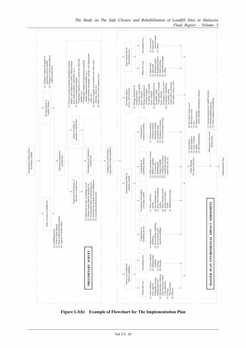
Generally, the Implementation Plan shall be implemented according to landfill management activities as set out in Figure I-3(a). The stages are as follows:
i. Stage 1 – Planning ii. Stage 2 – Design/Construction iii. Stage 3 – Operations and Maintenance iv. Stage 4 – Closure (Post Closure)
Figure I-3(a) Implementation Plan for Sanitary Landfill System and its Inter-relationship with Other Processes
Figure I-3(b) shows an example of the flowchart for the Implementation Plan for a particular Sanitary Landfill System in Japan.
SWM Master Plan
Basic Plan for Disposal System
Commencement of Waste Receiving
Detailed Design of Landfill Site
Safe Closure Plan (PC & PCM plan)
Post-closure Land Use Plan Environmental Impacts
Assessment (EIA)
Environmental Management/Monitoring
Flow of Landfill Site Environmental Consideration/Registration
Safety Closure & Post-Closure Utilisation
Initial Environmental Examination (IEE)
Plan
ning
St
age
Des
ign/
C
onst
ruct
ion
Stag
e
Ope
ratio
n St
age
Clo
sure
St
age
Landfill Site ConstructionRegistration of New/
Operating Landfill Sites
(10 years after PC)
Landfill Operation/ Land filling Control
Completion of Land filling
Physical Closure (PC)
Post Closure Management (PCM)
Provisional Land-use
Post-closure Land Use
Registration of Closed Landfill Sites
Environmental Management/Monitoring
(Leachate, Gas & Settlement)
Records
Tech
nica
l Gui
delin
e on
San
itary
Lan
dfill
G
uide
line
for S
afe
Clo
sure
The Study on The Safe Closure and Rehabilitation of Landfill Sites in Malaysia Final Report – Volume 5
Vol 5-I- 10
Figure I-3(b) Example of Flowchart for The Implementation Plan
Stud
y on
Sca
le o
f Lan
dfill
Site
Esta
blis
hmen
t of B
asic
Pol
icy
for S
anita
ry L
andf
ill
Des
ign
Capa
city
of
Land
fill V
olum
e
Sele
ctio
n of
Alte
rnat
ive
Land
fill S
ites
Neg
otia
tion
With
Ow
ners
of
Alte
rnat
ive
Land
fill S
ites
Stud
y on
stab
ility
of
Alte
rnat
ive
Land
fill S
ites
Det
erm
inat
ion
of A
ltern
ativ
eLa
ndfil
l Site
s
Com
plet
ion
fo a
ll Pr
oced
ures
(Agr
eem
ent o
n la
nd a
cqus
ition
)
Surv
ey to
be
Con
duct
edB
efor
e La
ndfil
ling
Impl
emen
tatio
n Pl
an fo
r Sa
nita
ry L
andf
illEn
viro
men
t Im
pact
Surv
ey a
nd A
sses
men
tIm
prov
emen
t Pla
n fo
r Su
rrou
ndin
g A
rea
Exam
inat
ion
ofLa
ndfil
ling
Syst
emEx
amin
atio
n of
Fac
illiti
esat
San
itary
Lan
dfill
Exam
inat
ion
onLa
ndfil
ling
Met
hod
Exam
inat
ion
of
Trea
tmen
t Fac
illiti
esSu
rroun
ding
Are
aW
ithin
Site
Are
aW
ithin
Site
Are
aSu
rrou
ndin
g A
rea
(1)
Land
con
ditio
ns(2
) H
ydro
geol
ogic
con
ditio
n(3
) Ec
olog
y(4
) D
isas
ters
(1)
Land
con
ditio
ns*a
rea,
cap
acity
*t
opog
raph
y, g
eolo
gy*u
nder
grou
nd w
ater
(2)
Hyd
roge
olog
ic c
ondi
tion
*flo
w sp
eed
and
volu
me
*wat
er u
tilisa
tion
(3)
Ecol
ogy
*flo
ra a
nd fa
una
(4)
Dis
aste
rs
(1)
Impr
oved
ane
robi
c la
ndfil
ling
(2)
Sem
i-ane
robi
c la
ndfil
ling
(3)
Re-
circ
ulat
ion
sem
i-
a
nero
bic
land
fillin
g
(1)
Wat
er c
olle
ctio
n
fa
cilit
y(2
) G
as d
isch
arge
d ve
nt(3
) R
ain
wat
er re
ctic
ulat
ion
Faci
lity.
(4)
Wat
er re
tent
ion
faci
lity
(5)
Dis
aste
r pre
vent
ion
faci
lity
(6)
Adm
instr
atio
n fa
cilit
y
(1)
Was
te se
pera
tion
of m
ixed
(2)
Mill
ed o
r unm
illed
(3)
Cove
ring
plan
(4)
Mou
ldin
g pl
an(5
) H
eigh
t of l
andf
ill(6
) La
ndfil
ling
mec
hine
ry(7
) La
ndfil
ling
tech
niqu
e
(s
andw
ich,
cel
l, et
c.)
(1)
Leac
hate
trea
tmen
t
*t
reat
men
t met
hod
*dis
char
ged
volu
me
(2)
Trea
tmen
t of g
as(3
) Tr
eatm
ent o
f rai
nwat
er(4
) Pr
even
t blo
win
g of
was
te
(1)
Dur
ing
cons
truct
ion
of L
andf
ill fa
cilit
ies
*air
qual
ity, w
ater
qua
lity
*noi
se, v
ibra
tion
(2)
Dur
ing
cons
truct
ion
of
tr
eatm
ent f
acili
ties
*air
qual
ity, w
ater
qua
lity
*
nois
e, v
ibra
tion
(3)
Dur
ing
land
fillin
g pr
oces
s
*a
ir qu
ality
, odo
ur
*w
ater
qua
lity,
soil
qual
ity
*no
ise,
vib
ratio
n
*S
cave
nger
s, in
sect
s, cr
ows
(4)
Com
plet
ion
of la
ndfil
ling
*ai
r qua
lity,
odo
ur
*w
ater
qua
lity,
soil
qual
ity
*
Scav
enge
rs, i
nsec
ts, c
row
s
(1)
Spor
ts fi
eld
(2)
Ope
n pa
rk(3
) B
otan
ical
gar
den
(4)
Res
iden
tial l
andu
se(5
) Pu
blic
faci
litie
s(6
) A
gric
ultu
ral l
andu
se(7
) O
ther
s
(1)
Acc
ess r
oad
(2)
Rain
wat
er
re
tent
ion
pond
s(3
) O
ther
s
Publ
ic H
azar
dsPr
even
tion
Mea
sure
s
Impl
emen
tatio
n Pl
an
Mai
nten
ance
Sys
tem
for
Dis
posa
l Site
(1)
Air
polu
tion
(2)
Wat
er p
ollu
tion
(3)
Noi
se, v
ibra
tion
(4)
Odo
ur(5
) So
il co
ntam
inat
ion
(6)
Scav
enge
rs, i
nsec
ts, c
row
(2)
Blo
win
g of
was
te(3
) Fi
re(4
) N
atur
al d
isas
ter
(flo
od, l
ands
lide,
em
bank
men
t col
laps
e)
(1)
Dur
ing
cons
truct
ion
of la
ndfil
l fac
ilitie
s(2
) D
urin
g la
ndfil
ling
proc
ess
(3)
Afte
r com
plet
ion
of la
ndfil
ling
MA
STE
R P
LA
N E
NV
IRO
ME
NT
AL
IM
PAC
T A
SSE
SSM
EN
T
(1)
Chan
ge in
vol
ume
and
qual
ity o
f
g
ener
ated
was
te fo
r lan
dfill
(2)
Chan
ges i
n vo
lum
e an
d qu
ality
of
col
lect
ed so
lid w
aste
(1)
Land
fillin
g pe
riod
(2)
Tren
d of
was
te d
ispos
al(3
) W
aste
col
lect
ion/
haul
ing
capa
city
(4)
Cap
acity
of t
rans
fer s
tatio
n
(1)
Subm
issi
on o
f stu
dy o
n su
itabi
lity
of si
te(2
) U
ltim
ate
land
use
plan
for l
andf
illed
site
(3)
Envi
rom
enta
l im
pact
on
surro
undi
ng a
rea
(4)
Am
uini
ties f
or re
siden
ts of
surr
ound
ing
area
(5)
Long
-term
mon
itorin
g sy
stem
(1)
Surv
ey o
n so
cial
env
irom
ent (
Popu
latio
n, In
dust
ry,
land
use,
wat
er u
tillis
atio
n, tr
affic
, cul
tura
l her
itage
asse
ts, p
ublic
faci
llitie
s, re
late
d la
ws,
etc.
)(2
) Su
rvey
on
natu
ral e
nviro
nmen
t
*
Hyd
rolo
gic
cond
ition
(riv
er, c
oast
al a
rea,
lake
s and
mar
shes
, etc
.)
*
Clim
etol
ogic
con
ditio
n (w
ind
dire
ctio
n an
d sp
eed,
ra
infa
ll, te
mpe
ratu
re, h
umid
ity, e
tc.)
* La
nd c
ondi
tions
(top
ogra
phy.
geo
logy
, soi
l, un
derg
roun
d
wat
er, e
tc.)
(3)
Surv
ey o
n qu
ality
of e
nviro
nmen
t (ai
r, w
ater
, noi
se,
vib
ratio
n, o
dour
, etc
.)(4
) O
ther
s (flo
ra, f
auna
aes
thet
ics,
etc.
)
PRE
LIM
INA
RY
SU
RV
EY
The Study on The Safe Closure and Rehabilitation of Landfill Sites in Malaysia Final Report – Volume 5
Vol 5-I- 11
3.5 Basic Design Parameters
3.5.1 Target Lifespan / Target Year
The target lifespan shall be the designed operational duration of the landfill site and should be set at approximately 15 years of operations.
The target year shall be the year the designed lifespan shall be reached, for example, the year 2020, etc.
In general, the target year for the landfill should be the same as the target year as set out in the Master Plan for solid wastes disposal. Ideally, the target lifespan should be established for between 10 to 15 years after first formulating the plan. This corresponds to the policy of implementing adequate solid wastes treatment projects from the long-term plan.
Once the target year has been determined, considerations must be given towards finding a suitable site, carrying out financial analysis and determining the construction schedule of the landfill. Other considerations must also be taken into account, such as the projected quantity and analysis of wastes haulage, and consideration of the actual conditions on the designated service area. Such process of planning, surveys and preparation of the detailed design may take several years. Hence, in order to prevent excessive build up of waste, it is recommended to provide some reserve margin or buffer in the plan so that the life span of landfill may be increased by a further 10-year period, if necessary, to allow for the transition period.
3.5.2 Designed Landfill Capacity
a) The Designed Landfill Capacity (DLC) shall be determined by calculating the product of the sum of planned waste to be landfilled (ADLV) and soil covered (CMV) per year, by the number of years that the landfill is to be operated.
b) The Annual Designed Landfill Volume (ADLV) shall be determined by dividing the Annual Designed Landfill Weight (ADLW) by the specific weight (SWW) (or weight per unit volume) of the solid waste that is landfilled and compacted.
ADLV [m3/year] = ADLW [ton/year] / SWW [ton/m3]
c) The Cover Material Volume (CMV) shall be determined by dividing the Annual Designed Cover Material Weight (ADCMW) by the specific weight (SWCM) (or weight per unit volume) of Cover Material which is landfilled and compacted.
CMV [m3/year] = ADCMW [ton/year] / SWCM [ton/m3]
[Notes]
Usually, after determining DLC, the site which can secure the capacity which fills DLC is selected. The required area for landfill site depends on the situation of a securable site.
However, when DLC is first determined by the reason the site was already decided etc., target lifespan
will change according to DLC.
The Study on The Safe Closure and Rehabilitation of Landfill Sites in Malaysia Final Report – Volume 5
Vol 5-I- 12
(1) Designed Landfill Capacity (DLC)
The DLC is the ultimate designed volume of the landfill for the target lifespan, including the volume of waste and covering material that is landfilled and compacted. The DLC will be used to determine the physical size of the landfill and the total area required.
(2) Annual Designed Landfill Volume (ADLV)
The ADLV is the most important parameter in the equation necessary to determine the size of the landfill site for the proposed target lifespan. It is generally determined by calculating the correlation factor between the estimated average annual volume, or amount of the waste brought into landfill, by the reduced volume after compaction in the landfill.
The average annual volume of waste has to be estimated based on the historical records of the actual volume of waste landfilled, at least, for the past five years.
Alternatively, the ADLV can also be estimated by comparing the past records of the vehicle haulage volume (ton) and the landfill volume (m3) of the other LAs with similar urban populations and employing similar wastes treatment methods.
If only the data on the carrying capacity of vehicles is available, then the vehicle haulage volume (VHV) may be calculated using the following equation:
VHV [ton] = [Carrying Capacity (m3)] x [Typical Specific Gravity of Waste (ton/m3)]
The typical specific gravity of the various types of waste for the different types vehicles are tabulated in Table I-2 below.
Table I-2 Typical Specific Gravity of Waste
Type of Waste
Vehicle Type
Non-Combustible Waste
Combustible Waste
Bulky Waste Recyclable Waste
4 ton Open Dump Truck - 0.17 0.07 0.11
4 ton Compactor Truck 0.13 - 0.16 0.25 - 0.35 - -
Source: Data collected in Fukuoka City during 1981 to 1987
(3) Annual Designed Landfill Weight (ADLW)
The ADLW is the estimated weight of solid wastes to be landfilled during a particular year. It is estimated by taking into account of the types of waste, the average weight of the waste, the generation rate per capita and the population concerned. The average weight of the waste and the generation rate can be determined based on the historical records and past trends of the actual weight of waste collected from the households.
The projected solid waste amount should be estimated, up to the target lifespan, with increments of 5-year intervals. The solid waste amount will steadily increase year by year due to the following factors: • Increase in the population
• Expansion of service area coverage
• Increase in per capita generation rate with the rise in living standards*
• Increase in commercial activities
The Study on The Safe Closure and Rehabilitation of Landfill Sites in Malaysia Final Report – Volume 5
Vol 5-I- 13
•
* The increase in per capita generation rate should be estimated based on historical records and
past trends. If information is not sufficient, then a 2% per year increase factor should be used as
an approximate figure on condition that the review of the Master Plan be made based on the past
trends.
Example on the estimation of the projected solid waste amount, for the first 5 years.
Assumptions.
- Increase in the generation rate per capita = 2% per year.
- Increase in population = 4% per year.
1990: Sample population 500,000 Service coverage 70% Generation rate of domestic waste*1) 0.91 kg/capita/day Commercial and institutional waste 50 ton/day The total amount = 500,000 x 0.70 x (0.91x10-3 ) + 50 = 368.5 ton/day
1995: Population (4% per year increase) 608,000 500,000 x 1.045 = 608,000
Service coverage (increased by additional 10%) 80% Generation rate of domestic waste 1.0 kg/capita/day
0.91 x 1.025 = 1.0 Commercial and institutional waste 73 ton/day
(8% per year increase)*2) 50 x 1.085 = 73
The projected total amount = 608,000 x 0.80 x (1.0x10-3) + 73 = 559.4 ton/day
Thus, the above example showed that the projected solid waste amount for the first 5 years will increase from 368.5 ton/day to 559.4 ton/day, an increase of about 191 ton/day.
Note: *1) The waste generation rate of 0.91 kg/capita/day was taken from the estimated average generation rate for Malaysia, as tabulated in Table I-3.
*2) The annual increase rate of the commercial and institutional waste is usually greater than that of the domestic waste. The assumed annual increase rate of domestic waste is roughly calculated to be about 6% (2% + 4%). Therefore, for the commercial and institutional waste, the rate of increase of, say 8%, is assumed and adopted.
The Study on The Safe Closure and Rehabilitation of Landfill Sites in Malaysia Final Report – Volume 5
Vol 5-I- 14
(4) Waste Amount Generated
Estimated waste amount generated in Malaysia in the year 2002 is shown in Table I-3.
Table I-3 Estimated Solid Waste Generated in Malaysia
Note: - Data for Peninsula Malaysia is taken from publications by Ministry of Housing and Local Government, Malaysia, 2002 - Data for Sarawak and Sabah is taken from “NREB and DANCED, 2001”
The unit generation rate of solid waste in Malaysia is estimated to increase from 0.91 kg/capita/day in 2002 to 1.15 kg/capita/day in 2020. Based on population growth projections for the period 2002-2020, waste generation is estimated to increase by an average of 3.59% per year. Accordingly, waste generation amount in the year 2020 is estimated to 31,500 ton/day; equivalent to about 11,500,000 ton/yea.
(5) Specific Weight of Solid Waste (SWW)
The SWW (or weight per unit volume) of the solid waste that is landfilled and compacted is generally estimated from a range of data obtained from past records. Since solid waste is not homogeneous, and also subject to the variation in the compaction, the specific weight is usually expressed in a range of values and typical values is assumed. The typical specific weight is tabulated in Table I-4 below.
Table I-4 Typical Specific Weight of Landfill Waste Type of Waste Range (kg/m3) Typical (kg/m3)
Source: “Integrated Solid Waste Management Engineering Principles and Management Issues” by Tchobanoglous, Theisen and Vigil.
(6) Cover Material Volume (CMV)
There are many types of cover material that can be used ranging from gravel, sand, soil and some geotextile material. However, final cover material must be suitable for planting and sustain plant growth. Generally good top soil is recommended.
The cover material quantity is generally expressed as the thickness of the applied material. With the known thickness, the area of covering and the type of material to be used, the weight and volume can easily be calculated. The specific weight of the material varies according to the material quality and the degree of compaction.
The Study on The Safe Closure and Rehabilitation of Landfill Sites in Malaysia Final Report – Volume 5
Vol 5-I- 15
The cover material volume should be planned and estimated based on the required volume necessary for the daily cover material, intermediate cover material and final cover material.
3.5.3 Designed Composition of Solid Waste in Sanitary Landfill
The designed composition of the solid wastes generally refers to the components and types of waste, the moisture content and the specific weight the waste. The components can be further divided into two main groups, namely the organic waste and the non-organic waste. The type of waste is generally determined by the geographical and economical situation of the waste generation area or sector, and also determined by type of intermediate treatment method used. The determination of the waste composition will have to depend on past available information either from actual samples taken from existing landfill sites or from studies carried out by various institutions and governmental bodies. It may be necessary to periodically monitor and re-sample the waste being sent to the landfill sites in order to determine the variations in the waste composition. The waste composition data is crucial for the planning, design, operations and maintenance, and the post closure land use planning for the landfill.
Examples of the waste composition for Kuala Lumpur, Malaysia, are tabulated in Table I-5, and Table I-6, showing the percentage of the particular type of waste from the various sectors, for the wet and dry basis.
The waste composition will tend to vary according to the trends and changes in the social and economical development of the country. A more affluent society will result in more waste being produced but with recent awareness towards recycling, waste reduction, source separations, etc, the waste being sent to the landfill for disposal may be reduced and the composition changed.
Table I-5 Composition of Solid Waste (% wt, Wet Basis) in Kuala Lumpur (2002)
The Study on The Safe Closure and Rehabilitation of Landfill Sites in Malaysia Final Report – Volume 5
Vol 5-I- 16
Table I-6 Composition of Solid Waste (% wt, Dry Basis) in Kuala Lumpur (2002)
Composition (%) Residential Commercial Institutional Cleansing Light Industry
Mixed SW LI &
Comm
SW from River
Overall (mixed waste)
Combustible Food waste & organic
42.4 58.1 26.7 3.1 0.0 35.5 18.5 39.0
Mix paper 8.6 11.2 14.0 2.4 5.7 8.9 10.4 9.4 Mix plastic 25.9 17.1 27.4 3.4 20.4 14.3 52.9 22.9 Textile 2.1 0.7 0.7 0.4 0.8 12.2 0.7 1.7 Rubber & leather 1.2 0.7 0.1 0.0 0.0 1.5 1.1 0.8 Wood 1.2 4.3 1.0 2.9 14.3 1.4 0.0 2.6 Yard waste 4.7 0.5 16.5 11.4 1.4 2.6 7.3 5.3 Fine 0.7 0.2 0.7 0.0 0.0 0.0 0.6 0.5 Sub-total 86.8 92.8 87.1 23.6 42.6 76.4 91.7 81.7 Non combustible Glass 4.6 2.3 3.2 1.0 3.1 1.9 3.4 3.3 Ferrous 5.2 4.1 6.4 1.0 8.1 0.6 3.4 4.6 Aluminium 0.3 0.3 3.0 0.1 1.1 0.0 1.5 0.7 Nonferrous 0.0 0.0 0.0 0.0 0.0 0.0 0.0 0.0 Other inorganics 0.0 0.0 0.0 71.6 41.9 0.0 0.0 7.1 OBW 3.1 0.5 0.3 2.7 3.2 21.1 0.0 2.6 Sub-total 13.2 7.2 12.9 76.4 57.4 23.6 8.3 18.3 Total 100.0 100.0 100.0 100.0 100.0 100.0 100.0 100.0 Source: Nazeri (2002) Notes: 1. Mixed SW LI & Com. = Mixed Solid Wastes From Light Industry and Commercial 2. SW = Solid Wastes 3. For Light Industry, mixed solid wastes from light industry and commercial and solid waste from river – only one sample taken from each source
The Study on The Safe Closure and Rehabilitation of Landfill Sites in Malaysia Final Report – Volume 5
Vol 5-I- 17
Chapter 4 Formulation of Sanitary Landfill System
4.1 Functions of Sanitary Landfill System
4.1.1 Landfill Functions
The main functions of a sanitary landfill system are as follows:
• Storage and Treatment • Environmental Protection • Land Development
The Sanitary landfill system must be designed with consideration towards preserving the living environment by preventing undue incidents such as overflowing of the waste and leachate seepage; propagation of vectors and attracting wild animals; scattering of wastes; and emission of unpleasant odour.
As a waste disposal facility, the main function is in the storage and treatment so that the waste may be stabilised and the volume reduced. However, landfills are treated as dirty and undesirable by the neighbouring residents who tend to be more concerned about the environmental aspects and on land development aspects. Thus, it is necessary to plan and design the landfill system which can maintain a balance of the three functions.
(1) Storage and Treatment
An effective sanitary landfill must be designed to have the capability of storing and safely containing the waste with in its boundary and retaining the leachate from seeping out and polluting the surrounding environment. It is also necessary to prevent the waste from scattering and emitting unpleasant odour. It is essential that leachate quantity be reduced and treated. The amount of emitted gasses such as methane should also be minimised.
The storage and treatment function can be further divided into three standard sub- functions, these are the retaining function, seepage control function and treatment function.
a) Retaining Function
Each of the designated cells must be filled in an orderly manner and the landfill site must be kept in a workable condition throughout target lifespan of the site. The stability of the closed landfill must also be maintained over a predetermined period. Suitable retaining bunds, embankments, walls and dykes must be provided to retain the waste. Such waste retaining facilities must be maintained throughout the operational period, closure and also during the post-closure ultimate use period. The retaining structures must be robust and constructed to prevent against erosion and weathering.
b) Seepage Control Function
Leachate from the landfills must not be allowed to seep into the waterways, rivers,
The Study on The Safe Closure and Rehabilitation of Landfill Sites in Malaysia Final Report – Volume 5
Vol 5-I- 18
ground water sources, aquifers etc. Pollutants from the waste can be transported by contaminated water inherent in the waste layers and by rainwater or ground water percolating through the waste. As precautionary measures, it is essential that any excess water seeping in from the surrounding to the landfilled waste be minimised and diverted by the construction of surface drains for the storm water run-off and drainage.
Liner may also be installed at the bottom and sides of the landfill area as to prevent the leachate from seeping through and also to divert and channel the leachate to the leachate collection pipes and to the treatment facilities. The selection of the liner material must take into account of the stabilisation period and should last through out this period. Alternatively, selecting sites with non-permeable ground layer such as clay may be advantages as these layers will acts as natural barriers.
Once the landfilled waste has stabilised over a period of time, the effects on the surrounding environment due to leachate and gases will be lesser.
c) Treatment Function
The landfill can also be considered as a treatment facility whereby the solid waste undergoes a process of decomposition and stabilisation. The biological, physical and chemical changes occurring in the waste layers play an important role in the treatment process. Municipal solid wastes contain a large amount of organic putrescible matter and depend entirely on bacterial decomposition in the stabilization process.
As for the by-product of the decomposition process, such as leachate and gases, suitable treatment facilities should be provided in order to prevent and minimise further contamination and pollution to surrounding environment.
(2) Environmental protection function
The environmental protection function is essential to minimise and prevent harmful effects to human health and to protect the surrounding natural environment. Such harmful effects are caused by problems associated with the discharge of leachate for the landfill, emission of volatile greenhouse gases, foul odour, vectors and other forms of pollutants such as noise and disturbances.
a) Leachate (Prevention of Ground and Surface Water Pollution)
The quality of the leachate discharged from sanitary landfill system are bound by a series of environmental regulations and laws such as "Environmental Quality Act 1974", "Environmental Quality (Sewage and Industrial Effluents)", and other standards and by-laws adopted by the Local Authorities. Therefore the leachate discharge from sanitary landfill system must be treated to comply with the requirements as stipulated in the relevant laws.
Leachate from the sanitary landfill site may be harmful and contaminate the water sources if it was discharged without treatment. Adequate and effective leachate treatment system must be provided with sufficient treatment and retention capacity to handle the leachate quantity, and provided with enough buffer to treat any
The Study on The Safe Closure and Rehabilitation of Landfill Sites in Malaysia Final Report – Volume 5
Vol 5-I- 19
temporary increases in the quantity that may be caused by excessive rainfall.
b) Vectors
Landfill areas tend to become breeding and feeding for vectors and animals such as flies, rodents, birds and stray dogs. In order to minimise and prevent such occurrences, daily cover soil should be laid to cover up the landfilled wastes. Insecticides may be sprayed over the area to prevent the breeding of flies and insects. Perimeter fence should be installed to prevent wild and gracing animals from entering the site. This will also prevent human scavengers from getting to the waste.
c) Gaseous products
The main gaseous products emitted from the sanitary landfill site are methane, ammonia and hydrogen sulphide. The composition of the gases depends on the decomposition conditions of the waste layer, i.e. either aerobic or anaerobic. Attention must be paid to the anaerobic landfill that contains mostly organic waste which can produce significantly high concentration of methane. Excessive build up of such volatile gasses may ignite and cause explosions. Such hazardous conditions may persist long after the landfill has been closed. Most of these gasses are harmful to human and the surrounding but the amount produced at the landfill are generally low and not concentrated enough to have any immediate effect. It may be necessary to install gas-venting system to facilitate the dispersion of the gasses to the atmosphere.
d) Unpleasant Odours
There are generally two kinds of unpleasant odour that are emitted from the landfill site, i.e. the odour from the fresh putrid waste matter and the odour produced as the result of the decomposition process. It may be necessary to control the dispersion of such odour to the surrounding environment especially when the landfill site is located near populated areas. The recommended measure is to provide suitable cover material on the waste layer at the end of the day's activities. Another more enhanced method is to provide gas collection and treatment facilities.
e) Noise Pollution and Disturbances
Excessive noise and disturbances that may be cause by dusts or vibrations emitting from the landfill are a nuisance and causes discomfort to the neighbouring population. These are usually caused by activities associated with the waste transport vehicles, machinery used at the site or from the leachate treatment facilities. For the landfill located near populated areas, it may be necessary to improve on the way the site is operated by reviewing the waste transportation system, and the selection and use of machinery and equipment so as to limit the effects of noise pollution and nuisance.
(3) Post-Closure Land-use
Post Closure land-use must be evaluated and decided carefully with considerations
The Study on The Safe Closure and Rehabilitation of Landfill Sites in Malaysia Final Report – Volume 5
Vol 5-I- 20
towards the ground conditions, the environmental conditions and the surrounding conditions.
Ideally, post-closure land-use should be limited to non-residential and low-construction development such as for parks or recreational amenities. However, in the developing areas where residential and commercial land are in demand, the post closure land may be developed and used for low density and low rise buildings. Any such development must be carefully evaluated. Additional ground stabilisation and mitigation countermeasures may be necessary prior to constructions.
At the closed landfill site, the continuing decomposition process will result in ground settlement and subsidence over a period of time, and continuous emission of toxic gasses. Thus, it is recommended that for all the closed landfill sites, including those sites that have not been earmarked for redevelopment, continuous monitoring must be carried out in order to check on the environmental effects and their conditions.
4.1.2 Landfill Facilities
All the individual functions must be supported and provide with the relevant facilities in order to enhance the functionality and improve on the effective of the entire landfill system as an integrated SWM disposal facility.
The type of facilities to be provided can be divided into 3 groups, namely:
• The Operations Facilities • The Management Facilities, and • The Supporting Facilities
(1) The Operations Facilities
The operations facilities shall be the facilities necessary for the actual operations and use of the landfill site, i.e. the retaining structures, bunds, lining system, drainage system, leachate collection and treatment facilities, gas collection system, cover system, etc.
(2) The Management Facilities
The management facilities shall be the facilities necessary for the daily management activities of the landfill site. Such include the administration office, weighbridge and weighbridge station, etc.
(3) The Supporting Facilities
The supporting facilities shall be the common facilities necessary to support the other management and operations facilities such as access road, fencing, workshop, vehicle cleansing facility, fire-prevention system, etc.
The relationship between the individual functions and the necessary facilities is tabulated in Table I-7.
The Study on The Safe Closure and Rehabilitation of Landfill Sites in Malaysia Final Report – Volume 5
Vol 5-I- 21
Table I-7 The Relationship between the Functions and the Facilities in the Landfill
Environmental protection Functions Facilities St
orag
e an
d tre
atm
ent
Prev
entio
n of
gr
ound
wat
er p
ollu
tion
Prev
entio
n of
su
rfac
e w
ater
pol
lutio
n
Oth
ers
(Pre
vent
ion
of
air p
ollu
tion
and
livin
g en
viro
nmen
t)
Land
dev
elop
men
t
Solid waste retaining structure ++ + Ground water drainage system ++ Seepage control work + ++ Rainfall collection system + Leachate collection/treatment system + ++ ++ Daily cover facility + ++ ++ ++ O
pera
tions
Fac
ilitie
s
Gas treatment equipment + + Vehicles monitoring office ++ ++ Environmental monitoring facility ++ ++ ++ + Administration building + Weighbridge + M
Key: ++: Important relationship +: Mutual Relationship
4.2 Determination of Site Location
4.2.1 Site Selection
In the sanitary landfill site selection process, all necessary criteria such as the design capacity, target lifespan, social & environmental issues, operational effectiveness, cost, etc must all be assessed and evaluated. Some of the important criteria are a follows:
• Available area
• Surrounding environment / conditions
• Topography and geological conditions
• Transport infrastructure and access
• Post closure land-use plan
• Availability of supplies
The Study on The Safe Closure and Rehabilitation of Landfill Sites in Malaysia Final Report – Volume 5
Vol 5-I- 22
(1) Available Area
It is important to select the site with sufficient area for construction of the landfill to cater for expansions up to the target lifespan. Area must also be allocated for the supporting facilities such as the administrative buildings, leachate treatment ponds, access roads, perimeter drains, fencing etc. Additional area for the buffer zones (green belt) may also be necessary.
(2) Surrounding Environment/Conditions
The situation and conditions of the surrounding environment, and the neighbouring activities must be carefully assesses by paying particular attention to the following: • The surrounding development, i.e. housing, commercial, industrial, institutional,
agricultural, etc. Consideration must be towards the sensitivity of locating the landfill near to the populated areas.
• Proximity to rivers, watercourses, lakes, ponds, water intake points etc. Consideration must be towards preventing leachate or other pollutants from contaminating the area.
• Availability of basic utilities such as electric power supply, water supply and telephone lines.
• Meteorological conditions of the area so as to avoid the area with high rainfall and strong winds. This is to minimise the wastewater and drainage from the site, and to prevent the waste or cover material from being blown away.
(3) Topography and Geological Conditions
It is important to consider areas where minimal surface earthworks and soil disturbances are necessary, i.e. to minimise hill cutting or earth filling, and tree cutting. Swampy areas, areas prone to flooding, and areas prone to land sliding should be avoided. The ideal land must be flat with a hard non-permeable ground.
Soil investigation should be carried out in order to determine the ground conditions of the area and also to determine the locations of groundwater sources or aquifers.
(4) Transport Infrastructure and Access
Although the landfill site must be located as far away from populated areas, its main purpose is to receive waste from such areas and therefore a good transport infrastructure is essential and must not be isolated. The area must be easily accessible by the waste collection vehicles and all the landfill machinery, at all times. It is also important to consider the accessibility for the emergency response services in case of accidents or fire at the site.
(5) Post closure land use Plan
When the site has been selected, it will be gazetted by the authorities to be used as a landfill site for the duration of the target lifespan. However, after the landfill has been closed, the land may be used for other purposes. Ideally, post-closure land-use should be
The Study on The Safe Closure and Rehabilitation of Landfill Sites in Malaysia Final Report – Volume 5
Vol 5-I- 23
limited to non-residential and low-construction development such as for parks or recreational amenities. Nevertheless, decisions must be made during the selection process to assess and determine the post closure post closure land use for the area.
(6) Availability of Supplies
It is necessary to identify the availability of supplies and material in the surrounding area so that procurement and delivery may be expedited efficiently and economically. Such include the supply of cover material, machinery spare parts, etc. Proximity to supplier of cover soil for example will reduce the cost of transportation and thus reduce the operations cost of providing the daily covering.
4.2.2 Survey of Present Conditions
The present conditions of the site, i.e. the hydrological profile, topography, geography, geology, meteorology, biological diversity, etc must be surveyed and documented for a better understanding of the characteristic of the area.
The survey activities should be carried out during the environmental assessment stage so that enough data can be obtained for evaluation and planning during the project implementation evaluation stage. Some of the recommended survey parameters to be obtained as follows:
• Geological maps (Scale 1/2500 to 1/5,000), to indicate the surface layers, underground structures etc.
• Plant life distribution map (Scale 1/5000 or 1/1000), to indicate the types, location and density of trees, vegetation and crops, etc.
• Meteorological data and distribution map, to indicate the amount of rainfall, evaporation rate, wind speeds and directions.
• Hydrological data, to indicate the location of rivers, streams, basin or marshes, the normal water levels and the flood levels, water quality, etc.
• Underground water table diagram, to indicate the presence of aquifers and wells, together with information on the water quality.
• Soil profile diagram and characteristics, to indicate the physical properties, the N-value, core sampling rate, coefficient of permeability, electrical resistance, chemical components of soil, tests for heavy metal, etc.
• Demographic survey, to ascertain the population, distribution etc of the surrounding area
• Traffic survey, to obtain data of the traffic situation of the vicinity.
The Study on The Safe Closure and Rehabilitation of Landfill Sites in Malaysia Final Report – Volume 5
Vol 5-I- 24
4.3 Environment Protection
An environmental impact assessment (EIA) must be carried out to determine the impacts and effects of the sanitary landfill on the environment, such as the air quality, water, noise levels, vibration and disturbances, odour, and other sources of pollution.
The EIA must be carried out in accordance with the regulations and guidelines as set out in the Environmental Quality (Prescribed Activities) (Environmental Impact Assessment) Act, October 1987.
4.3.1 Environment Impact Assessment
Figure I-4 shows the flowchart for the recommended procedures for carrying out the EIA for the landfill planning of Malaysia.
Source: DOE, Environmental Impact Assessment (EIA) Procedure and Requirements in Malaysia, 1994
Figure I-4 Outline of Environmental Impact Assessment Procedure in Malaysia
Yes
ProjectInitiator
PrescribedActivity?
Preliminary Assessment
Detailed Assessment ReportReview(DOE)
Detailed AssessmentRequired?
No
Approving Authority
Project Approved?
Report Review
(Review panel)
More InformationRequired from Project Initiator
Report Accepted?
Detailed AssessmentReview Document
No
No
Yes (Specific projects which can have significant impact)
Yes
No
YesEvaluation subject to other requirements of environmental quality regulations under the Environmental Quality Act, 1974
Report Accepted?
More InformationRequired from Project Initiator
Yes
The Study on The Safe Closure and Rehabilitation of Landfill Sites in Malaysia Final Report – Volume 5
Vol 5-I- 25
4.3.2 Impact to the Surrounding Environment
It is important to consider the potential impact the landfill will have on the surrounding environment such as the increase in traffic and transporting activities, increase in odour and noise, etc.
Suitable countermeasure and improvement plan must be established that will minimise the impact and preserve the harmony between the landfill and the surroundings.
(1) Traffic/Transportation
One of the major impacts to the surrounding will be the increase in transportation and traffic activities due to the movement of refuse collection vehicles, cover material vehicles and machinery. The roads leading to the landfill must be properly maintained and improved to cope with the increase in the volume of traffic.
Sufficient ingress and egress to the landfill site must be provided as to prevent any congestion or traffic obstructions at the entrance.
(2) Harmonisation with Surrounding Environment
It is important that the presence of the landfill site will not overburden and destroy the harmony between the site and the surrounding environment.
Perimeter fencing and buffer zones, and planting of trees and bushes should be encouraged to beautify landscape and preserve the aesthetic view of the surrounding natural environment.
4.3.3 Environmental Monitoring Plan
The environmental monitoring plan must be established to provide continuous monitoring of the landfill site and its surroundings throughout the operations period and also during the post closure phase.
The environmental monitoring plan should include procedures on carrying out the necessary activities to monitor the effluent discharge such as the conditions of leachate, gaseous emissions, groundwater and surface water, etc.
Regular sampling exercise must be carried out and the samples analysed in order to assess the quality of the samples. The data collected from the monitoring activities can be used to assess the conditions and impact the landfill will have on the surrounding environment.
The Study on The Safe Closure and Rehabilitation of Landfill Sites in Malaysia Final Report – Volume 5
Vol 5-I- 26
4.4 Management of Sanitary Landfill System
The operations, maintenance and environmental monitoring activities must be managed efficiently with strict adherence to the laws and regulations, inline with the technical standards and requirements, and with consideration to the surrounding environment.
The management activities can be divided into three main activities, i.e. the operations management, the environmental management, and the closure management.
(1) Operations Management
The operations management includes managing the activities of the day to day operational functions of the landfill, from management of the transportation traffic flow, the landfilling procedures, laying of cover material, management of the supporting facilities, collection of tipping fees, etc. The keeping of daily operational logs, records and relevant data must also be carried out.
(2) Environmental Management
The environmental management includes managing the necessary activities related to preserving and protecting the environment, such as monitoring the leachate and gasses emissions, Managing the effluent discharge after treatment, prevention of scavengers and propagation of insects, preserving the aesthetic and harmony of the surrounding, etc. The keeping of regular monitoring logs, test results, records and relevant data must also be carried out.
Consideration must also be given to the social aspects of management, i.e. managing the staffs and suppliers, fostering good relationships with the councils, clients, and with the surrounding residents.
(3) Closure Management
Consideration for the safety closure and post closure utilisation must be made during the operations stages. The closure management activities will include monitoring and ensuring that the landfill site has been operated satisfactory so that safety closure activities can be carried out in the future. Such activities included the monitoring of the stabilisation of the waste layers, the ground settlement, planning for the final cover and landscaping, etc.
The Study on The Safe Closure and Rehabilitation of Landfill Sites in Malaysia Final Report – Volume 5
Vol 5-I- 27
4.5 Performance Indicators for the Landfill Management/Control
The performance indicators for the landfill management/control comprises of the following parameters.
• Waste record • Landfill works • Facility and equipment • Environmental protection and monitoring • Social consideration
In line with new privatisation programme as encouraged by the Government of Malaysia, the landfill operation concessions have been awarded to private contractors to operate and to maintain the landfill. The Government will still maintain the responsibility for the overall management and control of landfill operation.
The main parameters for the performance indicators for the landfill management/control are shown in Table I-8 below.
Table I-8 Performance Indicators for the Landfill Management/Control
Items Indicators
1. Waste Records
• Amount of waste received • Record of incoming collection vehicles • Number of checks of arriving waste and the results • Total accumulated waste and remaining capacity • Density of filled waste • Amount of recycling carried out at landfill site
2. Landfill Works
• Amount of waste disposed • Records of filling by area/cell/phase • Amount of cover soil provided • Records of accident and hazard incidents
3. Facility and Equipment
• Records of Operations and Maintenance (O&M) of landfill facilities (including expenditures)
• Records of landfill equipment O&M (including cost) • Records of staff attendances
4. Environmental Protection and Monitoring
• leachate quality and quantity • Landfill gas quantity and quality • Surface water quality • Groundwater quality • Odour, scattered waste, dust, vector etc. • Ground settlement
5. Social Considerations • Records of public complaints • Scavenging activities (if any) • Records of visitors
The Study on The Safe Closure and Rehabilitation of Landfill Sites in Malaysia Final Report – Volume 5
Vol 5-I- 28
4.6 Post Closure Land-use Plan
The post-closure land-use plan must be considered and planned at the initial stages of the planning of the landfill, however such plan will only be implemented after the safety closure of the site has been carried out. It is necessary to formulate the improvement plan such that it will become possible to use the land after the landfill has been closed safely. The post closure land use plan can be used to plan and decide on how the landfill should be operated, the covering material to be used, the depths of the waste layers, etc.
In the preparation on the post closure land use plan, consideration must be towards the stability of the closed site, and the period of time required for the completed landfill to stabilise. The stabilisation process depends on the types and volume of the solid wastes, types and volume or thickness of cover material applied, the type and method of intermediate treatment processes being carried out such as crushing or compaction. All these factors must be evaluated to confirm whether the land of the closed site is suitable for the proposed post closure land use.
Prior to implementing the post closure land use plan, it is important to ensure that all the factors that have impact on the environment be dealt with and active countermeasure are in placed. Such include ensuring that proper post-closure procedures have been carried out prior to closure; all leachate and gasses discharge are being monitored and treatment facilities provided; the slopes and ground have been properly compacted and showing no signs failure; and all the waste have been properly covered and all pollutions are being contained.
In order to determine the suitability and evaluating the stability of the closed site, all necessary tests and ground/soil analysis must be carried out so that the data obtained may be used to estimate the degree of stability, to predicted subsidence rate, and to estimate the load bearing capacity of the ground.
4.7 Other Considerations
4.7.1 Compliance to Other Guidelines and Standards
In addition to complying to the series of laws and regulations related to solid waste management, some Local Authorities have set up a series of local government guidelines and standards which must be adhered to. Such additional standards may be decided on a case-to-case basis and the conditions may vary depending on the present situation and circumstances. However, there are also conditions whereby exemptions, variations or contraventions to certain regulations may be granted by the relevant authorities.
Although all the best endeavours will be put towards complying to all the laws and regulations in the planning and setting up the new landfill, not all regulations or standards can be met and contravention order, variation or exemptions may be submitted to the authorities for their consideration.
Generally there are three levels of application for the exemptions, they are;
The Study on The Safe Closure and Rehabilitation of Landfill Sites in Malaysia Final Report – Volume 5
Vol 5-I- 29
Level A : • Exemption from strict adherence to the Development Regulations that requires approval by the Local Authority
• Exemption to regulations that are not applied to construction of the sanitary landfill system.
Level B : • Exemption to conditions that requires approval by the State Government.
• This may also require the acknowledgement by the relevant Federal Department or Ministry. However, this process relatively simple.
Level C : • Exemption to conditions that requires approval from the Federal Government
Generally, Level A or Level B are preferred, however, there are increasing cases where it becomes necessary to select a site for which Level C is applied. In such cases, it is necessary to take into consider the period required for application and obtaining approval.
4.7.2 Occupational Health and Safety
It is essential to protect the occupational health and safety for the workers and also the general health and safety of the public. These can be achieved by fostering good housekeeping philosophies, good hygiene conditions and implementing strict safety directives.
The landfill site can be considered to be a hazardous workplace considering the unsanitary nature and danger present at the site. The putrid wastes are full of harmful bacteria and pathogens that are detrimental to human health. The proliferation of vectors such as flies, mosquitoes and wild animals feeding on the waste; the presence of sharp and hazardous objects, toxic chemical spillages and fumes, noxious gasses emissions, all pose a health hazard to the workers and to the general public. Other hazards such as gaseous explosions, fire, land slides etc are also a great concern for the workers.
(1) Prevention of Hazards
In order to prevent and preserve the well being and safety of the workers, the landfill must be operated with considerations to eliminating the potential courses of the hazards and to prevent accidents from occurring. All these can be achieved by adopting good housekeeping practices and good safety practices. Some of the major steps to be taken are:
• Eliminate the presence of vectors by installing fences, laying the cover material and spraying of insecticide.
• Minimising excessive pilling of waste to prevent waste sliding • Preventing fire by banning all form of open burning of waste and smoking • Provide suitable covering and compaction to ensure all dangerous and sharp
objects have been properly covered • Provide proper gas collection and dispersion systems, and monitoring all gas
emissions
The Study on The Safe Closure and Rehabilitation of Landfill Sites in Malaysia Final Report – Volume 5
Vol 5-I- 30
• Provide proper leachate collection and treatment systems • Implement proper vehicles traffic system to prevent accidents • Provide suitable vehicle washing facilities and disinfections systems
(2) Workers Welfare Amenities and Health Care Facilities
Proper health care management philosophy may be implemented to provide the adequate emergency treatment and support to the workers and to develop a suitable working environment which is healthy and pleasant to work in. The basic necessities are:
• Provide all workers with proper safety gears
• Provide regular emergency and safety training to the workers
• Provide washing and cleansing facilities for the workers
• Provide standard emergency medical supplies
• Provide regular medical check-up for the workers.
4.7.3 Weather Conditions
The design and planning of the landfill must take into account of the local weather conditions and seasonal climatic changes. The type of facilities provided, the operations and maintenance methodologies, etc must be able to support the landfill throughout the year during both the dry or wet weather conditions. Emergency response plan must also be establish to cater to abnormal weather conditions such as flash floods, drought or high winds.
In Malaysia, the tropical climatic conditions are generally either wet or dry, with heavy rainfall during the wet monsoon season and occasionally drought during the dry season.
(1) Wet Season
During the wet season, the rain usually comes in short burst of rainfalls, and during the monsoon season storms and heavy rainfall could last for a long period of time. In the design of the landfill, it is essential that proper rainwater drainage systems are provided together with the provision of adequate leachate collection and retention facilities.
Additional waste surface cover may have to be provided in order to minimise the rainwater from penetrating into the layers. Suitable drainage network system must also be provided on the cover surface to collect and diverted the rainwater to the perimeter stormwater drains.
Excessive rain will also result in flash flooding and causing soil erosions. Hence it is important to constantly monitor the conditions of the retaining walls, water retaining structures, the slopes, access roads etc.
(2) Dry Season
During the dry season, there could be periods of time without any rainfall and the grounds
The Study on The Safe Closure and Rehabilitation of Landfill Sites in Malaysia Final Report – Volume 5
Vol 5-I- 31
and earth roads can become very dry and dusty. It is important to ensure that the level of airborne dust be minimised by monitoring the activities of laying the cover soil, the wind conditions, and also monitor the vehicles movements. It may be necessary to spray water on the dry roads to wet down the dust and to prevent them from being airborne.
4.8 Rehabilitation of Waste Landfill Site
Waste landfill sites which have not been properly operated and/or proper landfill facilities have not been facilitated shall be rehabilitated as soon as possible, in order to minimize environmental risks caused by the landfill sites.
Based on the landfill inventory survey carried out by the JICA study in the year 2003, named “The Study on the Safety Closure and Rehabilitation of Landfill Sites in Malaysia”, more than 90% of landfill sites in Peninsula Malaysia are open dumping or level 1, and are therefore sources of environmental risks.
Rehabilitation of existing landfill sites shall be carried out sooner based on the technical components described in this guideline.
Part II
Technical Guideline on Sanitary Landfill System
The Study on The Safe Closure and Rehabilitation of Landfill Sites in Malaysia Final Report – Volume 5
Vol 5-II- 1
Part II Technical Guideline on Sanitary Landfill System
Chapter 1 General
1.1 Integrated Landfill Facilities
A proper sanitary landfill must be provided with all the necessary facilities in order for the system to function effectively. The supporting and ancillary facilities must be integrated with the core facilities to form the Sanitary Landfill System.
A typical sanitary landfill system must be provided with all the necessary facilities as shown in Figure II-1. Generally the sanitary landfill system comprise of the core facilities, such as the waste retaining facility, leachate collection piping facility, gas vents, access roads, drainage system, fencing etc; and the supporting facilities, such as the leachate treatment facility, administrative facility, machineries etc.
The supporting facilities must be able to function independently as individual standalone facilities. However, their functions are generally interdependent and should be operated as integrated facilities, mutually support each other's functions. The design of the individual facilities differs from site to site, depending on the size, the requirements and the design service lifespan. All the facilities must be designed to operate and used throughout the designed target lifespan of the landfill. Some facilities must also be able to function beyond the target lifespan, i.e. to function even after the closure of the site. Such facilities include the gas venting systems, the leachate collection and treatment facilities etc.
Figure II-1 Typical Sanitary Landfill System
Buffer Zone
Fence
Notice Board
Approach Road
Weighbridge
Drainage Ditch
Access Road
Gas Venting Pipe
Cover Soil
Retention Ditch
Leachate Control Pond
Aerator
Gas Venting Pipe
Landfilled WasteRetaining Bund
Liner
RecirculationPump
Completed Area
Leachate Collecting Pipe
Working Face
The Study on The Safe Closure and Rehabilitation of Landfill Sites in Malaysia Final Report – Volume 5
Vol 5-II- 2
1.2 Classification of Sanitary Landfill Levels
The level of improvement of the sanitary landfill system can be classified into four (4) levels. They are;
Level 1: Controlled tipping
Level 2: Sanitary landfill with a bund and daily cover soil
Level 3: Sanitary landfill with leachate recirculation system
Level 4: Sanitary landfill with leachate treatment facilities
The classification is used to determine the required standard of improvement to be achieved based on considerations to the site conditions, financial constraints, proposed technology, post closure land use, etc.
* "Sanitary Landfill" is defined as follows.
A method of disposing of solid wastes on land without creating nuisances or hazards to public health or
the environment. Using the princeples of engineering the solid waste is confined to the smallest practical
area, reduced to the smallest practical volume, and covered with a layer of earth at the conclusion of
each day's operation (daily cover), or at more frequent intervals as may be necessary.
The levels are also used to determine the environmental impact and countermeasure of the landfill. The higher the level will result in lower environmental impact and thus fewer countermeasures will be necessary for closure and subsequent post closure utilisation.
New landfill should be designed to achieve Level 3 or Level 4, whilst for the existing landfill sites, the rehabilitations and improvement targets must achieve Level 3 or below. Landfills that do not meet the minimal standards are considered as open dump sites and should not be encouraged. Such sites must be closed safely and immediately.
The summary of the classification of the levels and the proposed facilities are tabulated in Table II-1.
The Study on The Safe Closure and Rehabilitation of Landfill Sites in Malaysia Final Report – Volume 5
Vol 5-II- 3
1.2.1 Level 1
The level 1 is the lowest level to be adopted by any a sanitary landfill system. Basically waste is just dumped on the landfill in a controlled manner and levelled. Soil cover should be laid periodically.
(1) Target • Introduction of controlled tipping. Waste shall be dumped in an orderly manner.
(2) Achievements • Provision of well maintained access to the site
• Provision of periodic cover material to prevent scattering of wastes, minimise odour and fire
• Provision of basic management systems to inspection, control and daily logs of incoming wastes.
(3) Necessary Improvements to the Next Level • Establishment of the site boundary
• Provision of environment protection facilities
• Provision of basic staff amenities such as office space, toilets, locker room
• Introduction of semi-aerobic sanitary landfill.
(4) Environmental Issue
Since only periodic cover materials are provided, the environmental impacts are still present, such as: • Surface and groundwater pollution by leachate
• Scattering of waste and dusty
• Breeding of insects and rodents
• Unpleasant view of landfill
• Noise pollution
• Unpleasant odour
1.2.2 Level 2
The level-2 sanitary landfill shall be provided with the solid waste retaining structure, clearly defined cells and surface water drainage. The soil cover shall be provided daily.
The Study on The Safe Closure and Rehabilitation of Landfill Sites in Malaysia Final Report – Volume 5
Vol 5-II- 4
(1) Target • Sanitary landfill with a bund and daily cover soil
(2) Achievements • Establishment of site boundary to clearly demarcating the disposal site
• Provision of sufficient daily cover soil
• Provision of surrounding bund to contain the waste
• Provision of surface and perimeter drainage system to divert the storm water
• Provision of environment protection facilities such as buffer zone, litter control and gas ventilation facilities
• Introduction of semi-aerobic sanitary landfill by providing gas ventilation facilities
• Provision of basic staff amenities such as office space, toilets, locker room
(3) Necessary Improvements to the Next Level • Improvement of semi-aerobic sanitary landfill
• Provision of leachate collection system
• Provision of leachate treatment facilities
(4) Environmental Issue
In this level, since disposal site and drainage system are already established, landfill operations can be controlled effectively. With the application of sufficient cover and provision of some environment protection facilities, impacts from landfill operation will be much lower than Level 1. The installation of gas ventilation facilities will result in achieving semi-aerobic conditions. However, leachate is still not under control and a environmental monitoring system should be established.
1.2.3 Level 3
The level-3 is an improvement to the level 2 sanitary landfill by the provision of leachate collection and recirculation system. The leachate collected through a series of collection pipes will be recirculated back to the waste layer so that it may be reprocessed and further decompose to improve leachate quality. Recirculation will also promote faster evaporation and thus reducing the quantity of the effluent.
(1) Target • Sanitary landfill with leachate recirculation system
(2) Achievements • Establishment of leachate control by the installation of leachate collection,
recirculation and monitoring facilities
The Study on The Safe Closure and Rehabilitation of Landfill Sites in Malaysia Final Report – Volume 5
Vol 5-II- 5
(3) Necessary Improvements to the Next Level • Provision of leachate treatment system
• Establishment of semi-aerobic sanitary landfill
(4) Environmental Issue
The leachate accumulated at the bottom layer of landfill will be collected and recirculated thus improving the quality and reducing the odour by the semi-aerobic decomposition process. The installation of leachate collection pipes beneath the waste layers will also promote ventilation and allow oxygen to penetrate into the waste to maintain the landfill site in the semi-aerobic condition, and accelerate the stabilisation of the wastes.
1.2.4 Level 4
The level-4 is an improvement to the level 3 sanitary landfill by the provision of the leachate treatment facilities and liner system.
The liner system will act as barriers to provide sealing function by preventing the leachate from penetrating deeper into the ground. The leachate will flow to the collection pipes and diverted to the leachate retention pond for further treatment. Aerators or air diffusers will be provided to enhance and hasten the treatment process for the effluent to be discharged.
(1) Target • Sanitary landfill with leachate treatment facilities
(2) Achievements • Provision of leachate treatment facilities with the installation of oxidation pond, etc.
• Provision of liners to control the seepage
• Establishment of semi-aerobic sanitary landfill
(3) Environmental Issue
The provision of seepage control facilities and leachate treatment facilities will enhance and promote semi-aerobic decomposition, and thus hasten the waste stabilisation period.
The leachate treatment facilities should be able to treat and improve on the quality of the effluent for discharge to the drains or watercourses. However, if the effluent discharge quality have to adhere to the more stringent requirements of Environmental Quality Regulations 1979, then it is necessary to provide higher level of treatment facilities that are able to treat the effluent to the requirement of Standard A.
The Study on The Safe Closure and Rehabilitation of Landfill Sites in Malaysia Final Report – Volume 5
Vol 5-II- 6
Site Office
WeighbridgeApproch Road
Drian
Bund
Gas Removal
Divider
Drain
Buffer ZoneOn - site Road
Figure II-2(a) Typical Layout for the Level 2 Sanitary Landfill
Figure II-2(b) Typical Layout for the Level 3 Sanitary Landfill
Figure II-2(c) Typical Layout for the Level 4 Sanitary Landfill
Site Office WeighbridgeApproch Road
DrianBund
Buffer ZoneOn - site Road
Store
Monitoring WellWater TruckFence
2nd LevelCompleted Reclaimed Area
Drain 3rd Level
Leachate Colection Pipe
( Branch )
Gas Removal
( Main )
Divider
On Site Road Pump ShedRock Armour
4th Level
Retention Ditch
On Site Road
Monitoring Well
Fence 2nd LevelCompleted Reclaimed Area
Drain 3rd Level
Rock Armour
Monitoring Well
Water Truck
Completed Reclaimed Area
Drain
Drain
Site Office
Weighbridge
Approch Road
DrianBund
Buffer ZoneOn - site Road
StoreMonitoring Well
Car Wash
Sealant
Divider
Gas RemovalLeachate Collection Pipe
On SiteRoad Fence
Control House forOxidation Pond
Monitoring Well
Bund
The Study on The Safe Closure and Rehabilitation of Landfill Sites in Malaysia Final Report – Volume 5
Vol 5-II- 7
Chapter 2 Waste Retaining Facility
2.1 Functions of Waste Retaining Facility
Waste retaining facility is necessary to store the solid wastes in a safe manner, as well as to prevent overflow and collapse of the landfilled wastes.
Retaining facility are constructed to prevent overflow of landfilled wastes, collapse of working face and to ensure that the landfilled wastes are stored safely. In many cases, these structures also prevent discharge and seepage of leachate from the landfill site.
Generally a retaining facility is constructed to store waste, not water. However, in the event of an abnormal downpour, temporary retention of rainwater inside the retaining facility can happen. Hence, it is also crucial for the retaining facility to be able to store the water safely.
In short, the functions of retaining facility can be summarized as follows: • Store the designated landfill volume.
• Prevent collapse of working face and overflow of landfilled wastes.
• Prevent discharge of leachate and seepage from the landfill site.
• Retain rainwater temporarily in the landfill site safely.
• Retain wastes safely during the landfilling process as well as after completion.
2.2 Planning and Design Concepts
Waste retaining facility has an important function at sanitary landfill, thus its structure shall be planned and designed carefully with appropriate concepts.
(1) Planning and Design Concepts
Structures of the retaining facility shall have the abovementioned functions and at the same time be sufficiently strong. The basic criteria in the planning and design of retaining facility are functionality, safety as well as economic consideration. The guidelines for planning and design of retaining facility are: • Select structure that is suitable with the designed landfill configuration or landfill
type.
• Select structure that is suitable with the landform of the site areas and natural conditions such as geological and soil conditions.
• Ensure safety factor for loading on the structure. This includes considerations on landfill deadweight, pressures from landfilled wastes, water pressures, etc.
• Ensure the loading on foundation is below the acceptable bearing load.
• Install liner facility if required to prevent discharge of leachate or seepage from the
The Study on The Safe Closure and Rehabilitation of Landfill Sites in Malaysia Final Report – Volume 5
Vol 5-II- 8
landfill site to the surrounding areas.
• Predetermine the designed highest water level in the case when water needs to be temporary retained in the landfill site.
• Install appropriate stormwater collection facility so that to protect the foundation especially in the case when water retained in the landfill site overflows into the retaining facility during a heavy downpour.
• Take necessary countermeasures to prevent corrosion in retaining facility caused by wastes, leachate or underground water.
• Design structure to be harmonized with the surrounding environment.
• Select type of structure with consideration given to the ultimate use of the landfill site after closure.
• Select type of structure with consideration on the economical aspects and expected lifespan of the structure.
(2) Design Procedures
The type, structural configuration and foundation of the retaining facility vary according to its height, soil conditions, construction methods, landfilling plan etc. Some basics for design procedures are given as follows: • Investigation on the basic items required for the design such as types and
characteristics of wastes to be landfilled, topography of the construction site, geology, soil conditions and construction methods, etc.
• Comprehensive evaluation of the inter-relations between the above and the overall planning of the landfill, including the landfill lifespan, liner facility, leachate collection facility, leachate treatment facility etc. and their economic viability.
• Determine the design criteria required for the calculation of pressures caused by the landfilled wastes. Carry out stability analysis on the selected structural type and configuration.
• Calculate the stresses on each structural item. Determine all design parameters and make technical drawings.
The Study on The Safe Closure and Rehabilitation of Landfill Sites in Malaysia Final Report – Volume 5
Vol 5-II- 9
Figure II-3 Design Procedure of Waste Retaining Facility
2.3 Selection of Waste Retaining Facility and Structural Configuration
It is crucial to select an appropriate structure type of waste retaining facility in order to formulate an effective plan for landfilling activities. Factors to be considered in the selection are such as the topographical conditions, waste loading, soil conditions of the foundation etc.
Loading condition (Waste, leachate, dead weight, earthquake force, etc.)
Determination of design factors
Design of waste retaining facility
Pre-design of shapes
Relation with a masterplan Investigation of economical
efficiency
Calculation of stability
Calculation of stress intensityof each component
The Study on The Safe Closure and Rehabilitation of Landfill Sites in Malaysia Final Report – Volume 5
Vol 5-II- 10
(1) Types of Waste Retaining Facility
Examples of retaining facility for inland landfilling are concrete dike, bund, earth embankment, retaining wall, sheet piling etc. The design conditions and loading for each structure are different depending on its purpose.
Therefore, the most suitable structural configuration shall be determined based on the topographical conditions of the surrounding area, waste loading according to the landfilling plan and soil conditions of the foundation. At the planning stage, it is necessary to compare various types of structure. While in the design stage, it is important to reconfirm whether the structural configuration selected in the planning stage is the most viable and appropriate.
An example of actual design for the waste retaining facility is illustrated in Figure II-4 below.
Figure II-4 Enclosing Bund for Landfilled Waste Retaining Facility
2.4 Loading on Waste Retaining Facility
When waste retaining facility is designed, it is important to take into consideration the loading information such as empty weight, waste pressures, hydrostatic pressures, uplift pressures etc., which affects the lifespan and usage of the retaining facility.
The loads acting on the retaining facility are landfill dead loads, landfill layer pressures, static waste pressures, uplift force, pore water pressures etc. In order to select the types of loading to be considered in the structural design, decision shall be made based on information concerning the characteristics of wastes, topography, geology, soil conditions, expected lifespan of the facility, surrounding environment etc.
The loading conditions on the retaining facility are different depending on the size as well as the expected lifespan of the landfill site. For small landfill site, too large loading conditions shall be avoided so that the design of the retaining facility becomes more viable economically. A rational
Enclosing
On-site Road
1.
Earth TYPICAL
Estimated Settlement
Wast
Final
53
2.0m
2.0m
5.0m
0.6m
5.0m
0.5mEstimated Settlement Level
Earth Drain
Side Ditch
Enclosing Bund
The Study on The Safe Closure and Rehabilitation of Landfill Sites in Malaysia Final Report – Volume 5
Vol 5-II- 11
plan and design can be achieved by selecting the most appropriate structural type based on the evaluation criteria of safety, compatibility as well as economic consideration.
Table II-2 shows the design conditions for landfilled layer pressure established for several actual designs of landfilled waste retaining structures in Japan.
Table II-2 Design Examples of Waste Retaining Facility in Japan
In case of using concrete or stainless steel for the construction of waste retaining facility, accidents such as overflow of wastes may occur due to corrosion. Hence, corrosion prevention measures are necessary.
Corrosion control is important in order to prevent accidents such as the extrusion of landfilled waste due to reduction in material strength caused by corrosion. In selecting corrosion control measures, the causes of erosion shall be identified according to the working environment, whether it is due to leachate or gas produced by decomposition of wastes or other corrosive elements carried in the atmosphere, fresh water or seawater, underground or it could be due to chemicals oxidation etc.
(1) Concrete
The constituents of concrete are mainly calcium salts of silica acid, aluminium and ferric oxide. Therefore, the corrosion of concrete is caused by the chemical iterations of its chemical constituents where the degree of corrosion is different depending on the composition of mixture.
The corrosion prevention of concrete structure is basically to prevent concrete from losing its alkali condition. It is important to prepare a good cement aggregate mixture and control the concreting and curing processes. Other measures are such as coating the concrete with
The Study on The Safe Closure and Rehabilitation of Landfill Sites in Malaysia Final Report – Volume 5
Vol 5-II- 12
a layer of organic compound, paint or asphalt.
(2) Steel
Corrosion of steel can be caused by electro-chemical, purely chemical or biological mechanisms. The electro-chemical effects are more common. Some of the corrosion control measures for steel are:- • Mortar or concrete coating
• Organic compound coating
• Painting
• Application of electricity
Table II-3 shows the rate of corrosion of steel under different conditions.
Table II-3 Corrosion Rate of Steel
Corrosion Environment Corrosion Rate (mm/year)
Land Exposed and above ground level
Buried above ground water level
Buried below ground water level
0.1
0.03
0.02
The Study on The Safe Closure and Rehabilitation of Landfill Sites in Malaysia Final Report – Volume 5
Vol 5-II- 13
Chapter 3 Stormwater Drainage Facility
3.1 Functions of Stormwater Drainage Facility
Stormwater drainage facility is installed to reduce the amount of leachate generated from landfill sites. In other words, it functions to prevent stormwater from surrounding areas to enter the landfill sites. Simultaneously, stormwater dropped on the landfill site shall be discharged without any contact with solid wastes.
Following conditions are required for the construction of stormwater drainage facility: • Drains shall be constructed surrounding the landfill site to prevent the outside
stormwater from flowing into the landfill site.
• Dykes or embankments shall be installed if necessary to prevent the stormwater from landfill areas where landfilling activities have not started to flow into the waste layers.
• Drains shall be constructed on the surface of landfill final soil cover at completed landfill areas to separate the stormwater from leachate and drain off the stormwater from the landfill areas.
Rainfalls at a landfill site and its surrounding areas will flow into the landfill area depending on the topography of the area. The rainwater volume is usually much higher than the volume of leachate generated within the landfill site. If this rainwater was seeped into the waste layers, the leachate treatment facility will definitely become not capable to treat the fluctuating and large amount of leachate generated. In order to avoid such situation, it is necessary to separate as much as possible the stormwater from entering the waste layers by constructing a stormwater drainage facility surrounding the landfill area. However, the amount of stormwater on the surrounding area and its volume flowing into the landfill site are depending on the topography and condition of environmental disruption of the area.
3.2 Types of Stormwater Drainage Facility
The stormwater drainage facility can be classified into the following categories:
• Perimeter trench drain • Trench drain in landfill site • Landfill surface drain • Upstream diversion channel
Stormwater drainage facility serves as part of the overall drainage network in the sanitary landfill system to reduce leachate volume generation through removal of rainwater. It can be classified into the following categories as illustrated in Figure II-5 below. The conceptual illustration of the constituents in a stormwater drainage facility is shown in Figure II-6 below.
The Study on The Safe Closure and Rehabilitation of Landfill Sites in Malaysia Final Report – Volume 5
Vol 5-II- 14
Figure II-5 Classification of Stormwater Drainage Facility
(1) Perimeter Trench Drain
The perimeter trench drain is usually constructed surrounding the landfill site before the commencement of landfilling operation. It collects rainwater from the surrounding area and functions to prevent the stormwater from seeping into the waste layers. The catchments area for designing the total stormwater discharged volume shall be taken into consideration so that the drain would be able to handle stormwater from the surface of the final cover upon the landfill completion.
The longitudinal gradient of the perimeter drains are depending on the topographical conditions. Generally, 1 to 2% slope is adopted. It is important to take into consideration the erosion and hydraulic jump during the design process, which is caused by swift flow and sharp curves occur frequently at steep or undulating ground.
The commonly used perimeter drain structures are in-situ concrete-bed channel, U-ditch, corrugated flume etc.
Figure II-6 Concepts of Stormwater Drainage Facility
Stormwater Drainage Facility
Drainage Channel (Drain)
(Retention pond for
fire-fighting)
Perimeter trench drain
Trench drain In landfill site
Landfill Surfacedrain
Upstream diversionchannel
Trench drain around completed
landfill section
Trench drain around unworked
landfill section
Bunghole
Underground watercollection facility
Drain in unwork section
Perimeter drain
from unwork sectionValve controlling drainage
Drain in landfill sectionDischarge channel
Retention pit
On - going lanfill sectionDversio
n
channel
Unworksection
landfill section Diversion channel
The Study on The Safe Closure and Rehabilitation of Landfill Sites in Malaysia Final Report – Volume 5
Vol 5-II- 15
(2) Trench Drain in Landfill Site
Trench drains built in the landfill site function to expel rainwater from the landfill site before it reaches the landfilled waste layers. It can be further categorized into trench drains around completed landfill section and trench drains around un-worked landfill section.
The trench drains around completed landfill section is installed on the landfill site after the application of final cover soil in order to drain off the stormwater. On the other hand, the trench drains around un-worked landfill section are functioning to drain off the rainwater in the un-worked landfill section in order to avoid it from mixing with the wastes. The construction of this type of drain is desirable if section landfilling is undertaken. Sometimes the collected rainwater is discharged through the underground water drainage facility. However, if these drains were not carefully closed after the commencement of landfilling for this section, there will be possibility of leachate flow into the underground water drainage facility, which may create serious environmental pollution or disaster. Such planning and design concepts shall be avoided.
The common types of trench drains built in the landfill site are Hume pipes, synthetic polymer pipes, corrugated pipes etc.
(3) Landfill Surface Drain
Landfill surface drains are installed to drain off the surface stormwater after application of the final cover soil. Surface drains are dug to the required slope (commonly 1 to 2%) on the fully compacted final cover layer.
The rate of ground subsidence is high at the early stage of landfill completion. Therefore, it is better to adopt simple type surface drains such as an open ditch land with sheet liner in the beginning. When ground subsidence has settled down, concrete based ditch shall be constructed.
(4) Upstream Diversion Channel
Upstream diversion channel is built in case where the catchments areas of both landfill site and outside areas are too large and the perimeter drains is insufficient to drain off the stormwater from the surrounding areas. Generally, a bunghole is dug at the upstream of the landfill site. Collected stormwater will either run through the pipe network located at the landfill bottom or channels that are installed to recirculate the collected water within the landfill site.
Table II-4 summarizes different types of drain for the application of stormwater drainage facility.
The Study on The Safe Closure and Rehabilitation of Landfill Sites in Malaysia Final Report – Volume 5
Vol 5-II- 16
Table II-4 General Applications of Drain by Type
Trench Drain in Landfill Site Drainage
Channel
Type
Perimeter Drain Completed
Landfill Section
Un-workedLandfill Section
Landfill Surface Drain
Upstream DiversionChannel
In-situ Concrete Channel ++ ++
U-Ditch ++ ++ ++ ++
Corrugated Flume ++ ++ ++ ++
Corrugated Pipe ++ ++
Box Culvert ++
Hume Pipe or Synthetic Polymer Pipe ++ ++
Open Ditch and Sheet + + +
Soil Cement Channel + +
Notes: “+” indicates a temporary measure.
“++” indicates full-scale measure.
3.3 Planning and Design of Stormwater Drainage Facility
A stormwater drainage facility shall be able to withstand the deformation conditions of the landfill sites and configuration due to the progress of landfilling activities for long period starting from its commencement of operation until the landfill completion.
It also needs to be well adapted to changes in drainage pattern due to the progress of construction works and landfilling activities.
It is necessary to plan and design an overall compatible stormwater drainage facility that is able to function at all time.
(1) Planning and Design Concepts
Stormwater drainage facility shall be able to withstand the deformation conditions of the landfill sites caused by the progress of landfilling activities. It is necessary to plan and design an overall compatible drainage that is able to function at all time, regardless of changes in drainage pattern due to the progress of construction works or landfilling activities.
For example, in the planning and design of perimeter drain at the beginning stage of landfill operation, it is important to examine thoroughly the design height and drainage system at the time of landfill completion so that the correct flow volume can be determined. Based on this information, the required cross-sectional area of the drains can be calculated and the most appropriate drainage layout plan can be established.
The drains may sometimes be clogged by accumulated sands, sediments and gravels.
The Study on The Safe Closure and Rehabilitation of Landfill Sites in Malaysia Final Report – Volume 5
Vol 5-II- 17
Therefore, it is desirable to design the drains in a way that is easy to maintain and give ample cross-sectional areas so that to reduce accumulation of sediments, sands or gravels. Drains for discharging rainwater shall be separated from underground water drains.
On the other hand, the drain structure and cross-sectional area shall be designed with due consideration given to the topographical conditions. Under certain conditions, the access roads can also function as a stormwater drainage facility during rainfall. Figure II-7 shows the general procedures for designing the stormwater drainage system.
Figure II-7 Flowchart for Design of Stormwater Drainage System
(2) Calculation of Design Flow
The stormwater volume depends on rainfall intensity, catchments area, topography and land-use. It can be generally estimated from the following rational equation:
Q = 1/360 C. I. A
Where, Q = stormwater volume (m3/sec) C = Coefficient of flow (select appropriate volume in accordance with
topography of landfill catchments area or vegetation, etc.) I = Rainfall intensity (storm recurrence interval of 10 to 15 years (mm/hr))
Inventory of Study Area Volume
Set–up Design Rainfall Volume
Determine the Stormwater Collection Area
Calculate the Design Flow
Tentative Selection of Drain Layout, Longitudinal
and Horizontal Profile of Drainage System, etc.
Design of Drainage System
Yes
Are HydrologicalCalculation Acceptable? No
The Study on The Safe Closure and Rehabilitation of Landfill Sites in Malaysia Final Report – Volume 5
Vol 5-II- 18
A = Catchments area (ha)
Tables II-5 and Table II-6 show the coefficient of flow for different land-use types.
Table II-5 Coefficient of Peak Flow by Landform
Topographical Condition fp
Steep mountainous land
3rd Geological period mountain
Undulating land with vegetation
Flat farm land
Irrigated paddy field
River in mountain area
Stream in flat plain
Large river in flat plain
0.75 ~ 0.90
0.70 ~ 0.80
0.50 ~ 0.75
0.45 ~ 0.60
0.70 ~ 0.80
0.75 ~ 0.85
0.45 ~ 0.75
0.50 ~ 0.75
Table II-6 Coefficient of Peak Flow by Land-use Development
Stage of Land-use
Development fp Remarks
Before development 0.6 ~ 0.7 More than 70% of catchments area is forest, plain, farmland
After development (1) 0.8 Catchments area with less than 40% of impermeable surface
After development (2) 0.9 Catchments area with more than 40% of impermeable surface
(3) Determination of Cross Sectional Area
Generally the cross section for open drain is either rectangular or elliptical. It is necessary to design for a slightly bigger cross sectional area to compensate the accumulation of sands, sediments and gravels by using the following equation:
S = Q/V
Where, S = Cross-sectional area of flow (m2) Q = Discharge volume (m3/sec) V = Average flow velocity (m/sec)
The average flow velocity can be calculated by Manning’s equation as:
V = 1/n R2/3 T1/2
Where, V = Average flow velocity (m/sec) N = Manning's coefficient of roughness T = Gradient of channel R = Hydraulic Radius (m) = S/P
Where, S = Cross-sectional area of flow (m2) P = Wetted perimeter (m)
The Study on The Safe Closure and Rehabilitation of Landfill Sites in Malaysia Final Report – Volume 5
Vol 5-II- 19
Example on the design of stormwater drainage facility
Sample landfill site
Coefficient of flow 0.6
Rainfall intensity 100 mm/hr
Catchments area 5ha
Stormwater volume = 1 / 360 x 0.6 x 100 x 5 = 0.833 m3/sec
In case the cast-in place concrete drainage (width of 0.8m, a depth of 0.5m, Manning's coefficient of roughness of 0.017, slopes of 1/100) is considered, the cross-sectional area of flow will be calculated as follows.
Hydraulic Radius = 0.4 / 1.8 = 0.222 m
Average flow velocity = 1 / 0.017 x 0.2222/3 x 0.011/2 = 2.16
Cross-sectional area of flow = 0.833 / 2.16 = 0.39 m2
Thus the calculation result of the cross-sectional area of flow is just the same size with the considered drainage, the drainage can be adopted. (If the calculation result of the cross-sectional area of flow is widely different with the primary considered drainage, drainage size should be re-considered.)
The Study on The Safe Closure and Rehabilitation of Landfill Sites in Malaysia Final Report – Volume 5
Vol 5-II- 20
Chapter 4 Leachate Collection Facility
4.1 Functions of Leachate Collection Facility
Leachate collection facility is aimed at collecting leachate generated from the landfill site, channelling it to a pre-determined facility for treatment before discharging it to the environment. It also serves to supply air into the landfilled waste layers through the collection pipes for the semi aerobic sanitary landfill.
The general function of leachate collection facility is to quickly collect and channel the leachate generated from the landfilled waste layers to the leachate treatment facility. The leachate volume generated in a landfill shall be kept minimum and removed immediately to the leachate treatment facility, so that there will be no trapped leachate in the landfill site. This is important to ensure that the water pressure acting on the liner facility and landfilled waste retaining facility is minimized. In other words, the leachate collection facility in one of the very important factors has to be considered in the selection of liner facility.
In the case of semi aerobic landfill system, the leachate collection facility is also serves to supply air into the landfilled waste layers and subsequently enhance the entire gas venting processes.
4.2 Components of Leachate Collection Facility
Leachate collection facility consists of collection pipes, leachate retention pits, leachate control valves, etc. It needs to be conformed to the landfill conditions such as the topography of the landfill bottom or landfill structure. Ultimately it shall be able to collect and discharge leachate effectively.
The components of a leachate collection facility are depending on the landfill types and structures. General conceptual layout plans for leachate collection facility are shown in Figure II-8 and Figure II-9 below.
Figure II-8 The conceptual layout plan for leachate collection facility
In the planning of water retention pit and reticulation pipe, it is necessary to consider the division of functions and the compatibility of these facilities with leachate extracting and reticulation facilities.
Leachate CollectionFacility
Collection pipe
Bottom pipe
Inclined pipe
Vertical pipe
Trunk line
Branch line
Leachate retention pit/leachate control pond, valve (facility for extracting leachate)
Reticulation pipe (facility for transporting leachate)
The Study on The Safe Closure and Rehabilitation of Landfill Sites in Malaysia Final Report – Volume 5
Vol 5-II- 21
(1) Collection Pipes
a) Bottom Pipes
Ducting placed at the bottom of landfill sites for leachate collection. It comprises of trunk and branch pipes that are installed at a gradient to enable natural flow potential.
b) Inclined Pipes
Placed along the slope of the landfill sites and connected to collection pipes at the landfill bottom. Preferred to vertical drainage pipe which shall be avoided from the aspect of intermediate covering. It also serves as gas vent.
c) Vertical Pipes
Leachate collection pipes placed vertically in the landfill. The heights of the pipes will be extended vertically as landfilling continues. The bottom ends of the vertical pipes are connected with the bottom pipes. It can also serve as gas vent like the inclined pipes.
A. Retention Pit Outside Landfill
B. Retention Pit Inside Landfill
Figure II-9 Concept of Leachate Collection Facility
Valve
Transport pipe
Branchline of bottom pipe Inclined pipe
Vertical pipe
Trunkline of bottom pipe
Transfer pipe
Branchline of bottom pipe
Inclined pipe
Vertical pipe
Trunkline of bottom pipe
Leachate retention pit
Transport pipe
The Study on The Safe Closure and Rehabilitation of Landfill Sites in Malaysia Final Report – Volume 5
Vol 5-II- 22
(2) Leachate Retention Pits and Valves
Leachate collection facility shall be placed with considerations on the topographical conditions of the landfill bottom. It shall be able to function effectively in collecting and discharging the leachate from the landfill waste layers without clogging of the collection pipes.
Retention pit is the facility located at the terminal of the collection pipes from where leachate is pumped out. The pit may be located inside or outside the landfill site. The selection of location is related to leachate treatment facility, retention ditch, topographical and site conditions etc.
Valves are required if the leachate retention pits are located out of the landfill site. Leachate flow is regulated by the valves, care shall be taken to prevent the formation of "scales" on the valves. The valves shall be maintained and inspected regularly.
4.3 General Structure of Leachate Collection Facility
(1) Layout
Depending on the topography of the landfill site and landfilling method, the layout plans for subterranean leachate collection pipes can be designed as shown in Figure II-10.
(i) Straight Line Pattern (ii) Herring Bone Pattern (iii) Ladder Pattern
Figure II-10 Layout Plans for Bottom Pipe
For straight line pattern, one or several pipes are installed linearly and if the ground surface is very wide, several pipes can be laid out in parallel.
The herring bone pattern is formed by connecting branch pipes to the main pipes. Leachate is collected by branch pipes and discharged by the main pipes. Several sets of collection pipes can be arranged in the herring bone pattern for a large-scale landfill site.
The ladder pattern is commonly used on flat landfill site where it is difficult to achieve the required cross fall.
The Study on The Safe Closure and Rehabilitation of Landfill Sites in Malaysia Final Report – Volume 5
Vol 5-II- 23
The layout of bottom collection pipes must be located based on consideration given to the permeability of the landfilled waste and buffer sand layer on the liner, size as well as the topography of landfill site. Furthermore, for a semi-aerobic sanitary landfill system, the ability of the leachate collection facility to bring in outside air into the waste layers to enrich the aerobic conditions is also an important criterion.
In general, spacing between the bottom collection pipes is depending on the catchments area and whether it is a sectioned or separated landfill site. Experience in Japan shows a spacing of 20-30m is desirable. As for inclined collection pipes, the spacing can be set further apart, normally about twice that for the bottom collection pipes. Vertical collection pipes can also be treated in the same manner as the inclined collection pipes placed on cut surface. Nevertheless, in determining the pipe spacing, consideration shall be given to the influence of landfilling work as well as the permeability of landfilled wastes.
(2) Materials
a) Collection Pipes
The types of material chosen for collection pipes are crucial to ensure sufficient structural strength to accommodate the pressure at various depth and also anti-corrosive to the leachate. Generally, perforated Hume pipes or those made of synthetic polymer are commonly used as collection pipes. The perforated Hume pipes are very rigid, while the synthetic polymer pipes are highly flexible. Therefore, the choice shall be made based on a comparison of their respective characteristics with the landfill site conditions.
The pores on the perforated surface of the collection pipes can be clogged up easily. If packed gravels are used as collection pipes, their diameter shall be at least twice of the perforated pipes. It is advantageous to place packed gravels surrounding a perforated pipe as filter materials.
Table II-7 summarizes the characteristics of various types of collection pipes.
Table II-7 Types and Characteristics of Collection Pipe
Type of Pipe General Diameter
(mm) Characteristics
Perforated Hume Pipe 150 - 3,000 Commonly used as collection and discharge pipes. Very rigid structure and suitable for cases where deformation of pipe is not tolerable.
Perforated Polymer Pipe Reinforced Plastic Pipe (FRP and FROM pipes) Harden Polyethylene Pipe Harden PVC Pipe
100 - 1,500
Commonly used as collection and discharge pipes. Very flexible and suitable for cases where ground subsidence is expected. Generally resistive to corrosion. Light and relatively easy to install.
Permeable Concrete Pipe 100 - 700 Commonly used as collection pipes but pores can be easily clogged up.
Permeable Synthetic Polymer Pipe
100 - 600 Commonly used as collection pipes depending onmaterial. Pores can be easily clogged up.
Packed Gravels
Commonly used in small-scale landfill site as collection pipes. To compensate for clogging, diameter shall be more than twice that of perforated pipes. Preferably used together with perforated pipes
The Study on The Safe Closure and Rehabilitation of Landfill Sites in Malaysia Final Report – Volume 5
Vol 5-II- 24
b) Filter Materials
The filter materials are the materials used to cover the surrounding of the collection pipes in order to ensure its functionality. Pebbles, gravels and construction debris are normally used.
In selecting the type of filter material to use, the following points shall be considered: • Grain size distribution and diameter of the select materials shall be large enough so
that it does not clogged up easily by sands, wastes or scales.
• Filter materials also act as backfill materials, therefore, it is desirable that it has sufficient strength, low compressibility and high stability.
Based on the abovementioned, pebbles, gravels or construction debris of 50mm to 150mm diameter are suitable as filter materials. It is not desirable to apply a layer of sand or buffer blanket over the filter materials because their pores can be clogged up easily by the sands.
(3) Structures
a) Bottom Pipes
The bottom pipes are perforated pipes or packed gravels which are buried together with filter materials to prevent clogging. In order to prevent deterioration of the function of filter materials, the thickness of the filter layer shall be more than 50cm from the ground level (or above the protective soils cover on the liner). The efficiency of the collection pipes can be enhanced if proper filter materials are used.
Figure II-11 shows the typical design examples of bottom collection pipe.
The width of filter materials shall be three times more than the diameter of the pipe in order to ensure its functionality and to reduce direct vertical loading on the collection pipes. In the presence of liner, extra care shall be taken to ensure that the gravels and pebbles do not touch the liner directly. A protective layer of buffer blanket, sands or soil cover can be applied.
b) Inclined Pipe
It is relatively difficult to fix the filter materials around the inclined pipes placed on the cut-section. Plastic or anti-corrosive netting can be used to fix the shape of the filter materials. On a gentle slope, packed gravels can be used if measures to prevent the distortion of its shape are taken when packing the gravels. In addition, synthetic polymer material or permeable materials are also commonly used.
c) Vertical Pipe
In order for the vertical pipe to stand upright, the base shall be fixed and it is built up by packing filter materials around the pipe as landfilling works progress. Generally, the initial height of the pipe is recommended to be 4 to 5m.
Leachate collected by the vertical pipe is discharged by the bottom pipes. The vertical pipes can be located directly above the bottom pipes or connected to it in such a way to expedite the discharge of leachate. Figure II-12 shows an example for the design of
The Study on The Safe Closure and Rehabilitation of Landfill Sites in Malaysia Final Report – Volume 5
Vol 5-II- 25
vertical pipe.
A. WITH COVER MATERIAL
B. WITH PROCTECTIVE LAYER
C. WITHOUT SURFACE LINER
Figure II-11 Typical Design of Bottom Pipe
h
More than 50m
Protective layerCover material
More than 3D
Liner material
More than 3D
Protective layer
Buffer blanket
(4 ~ 10 )/mm
dProtective sand bag etc.
3d
3d
More than 3D
More than 3D
Cover material
More than 50m
Protective sand bag etc.
h
Protective layer
Liner materiald
Protective layer
(4 ~ 10 )Buffer blanket
m/m
3d
3d
More than 3D
More than 3D
Cover material
h
d
Base Material
3d
3d
The Study on The Safe Closure and Rehabilitation of Landfill Sites in Malaysia Final Report – Volume 5
Vol 5-II- 26
Figure II-12 Example of Vertical Pipe
4.4 Design Flow and Cross Sectional Area
It is necessary to determine the capacity of leachate collection facility based on leachate volume calculated by taking into account factors such as the climatic and topographic conditions, locations of other main facilities etc.
The cross-sectional area of collection pipe shall be determined not only depending on the size of catchments area but also the need to supply air into the waste layers particularly for the semi aerobic landfill system.
However, it is difficult to estimate the amount of air required. It is thus necessary to select a diameter size which is large enough to allow passage of air through the pipes.
(1) Design Flow
Under common conditions, the sources of leachate generation are basically waste moisture contents and rainfall. Generally, the effect of rainfall on leachate generation is tremendously large. Therefore, only the leachate generated by rainfall are considered and discussed in this section.
The size of leachate treatment facility is determined by the average daily discharge volume. However, leachate collection facility has to respond directly to the discharge volume. Sometimes its capacity may not be sufficient if the design is based on the average daily discharge volume.
Therefore, the design flow shall be done so that the leachate collection facility is able to handle high intensity of rainfall over a short period as shown in calculation for stormwater drainage facility.
An approximate method to express the relationship between rainfall and discharge volume is given by the Rational Equation. The design flow can be determined using the rainfall intensity and coefficient of discharge at the landfill site.
Gabion
Perforated Pipe
RebblesGabion
Rubbl
The Study on The Safe Closure and Rehabilitation of Landfill Sites in Malaysia Final Report – Volume 5
Vol 5-II- 27
(2) Rainfall Intensity and Coefficient of Discharge
The rainfall catchments area shall be kept as small as possible by applying section landfilling in a large landfill site. Coefficient of discharge shall be kept as large as possible because the time for leachate to remain in the landfill site shall be as short as possible. Coefficient of discharge of 0.6 ~ 0.7 can be used if rainfall intensity is about 30-50mm/hr. Thus, the design flow becomes Qmax < 0.06 ~ 0.lm3 /(sec-ha).
For a design flow of 0.06m3/sec, if the main leachate collection pipe made of 600mm diameter Hume pipe is placed at a gradient of 1%, then the discharge volume will be 10% of the full pipe capacity (about 0.6m3/sec) and its water depth is about 120mm or about 20% of the pipe’s diameter.
(3) Cross Sectional Area
The cross-sectional area of the leachate collection pipes shall include consideration for air and gas circulation besides the function of discharging leachate. For perforated pipes, it is sufficient to design the diameter to be 50% above that required by the design flow because the cross-sectional areas required by air and gas are assumed to be provided by the top portion of the pipe’s cross-sectional area.
Generally, main leachate collection pipes shall have diameters of larger than 600mm and branch pipes with diameters of more than 200mm.
4.5 Loading Conditions
Leachate collection pipes are under the pressures of waste and earth loads both in vertical and horizontal directions, so that it must be designed to suit with these pressure conditions.
Generally, leachate collection pipes have the following characteristics: • Pipes are buried very deep under the high embankment. However, the actual depth
depends on topography and types of landfill.
• The loadings on the collection pipes are changing at all time because the landfilled layers are being compacted continuously when landfilling activities progress.
• The pipes are able to discharge leachate with strong corrosive properties.
• Larger pipes shall be used to ensure smooth discharge of leachate and proper function of semi aerobic landfill system.
• The pipes may sometimes have to be constructed on weak foundation.
The collection pipes shall be designed under the loading conditions determined by landfilled layer pressure acting vertically and laterally.
(1) Vertical Force
The vertical force from landfilled layer varies depending on how the pipe is installed. If
The Study on The Safe Closure and Rehabilitation of Landfill Sites in Malaysia Final Report – Volume 5
Vol 5-II- 28
the pipes are buried inside a dug-out ditch, subsidence of the earth above the ditch can be prevented by frictional forces on both sides of the ditch. In this case the loading on the pipes is reduced. On the other hand, if the pipes are placed on the ground and then covered by embankment, subsidence of embankment can be prevented by the pipes. The pipes will experience not only the dead load of the cover earth but also frictional force on both sides. Vertical force acting on the pipes varies depending on its installation method and the conditions of backfill materials. The gravels placed on both sides of the pipes shall be compacted.
(2) Lateral Force
When the filter materials surrounding a pipe are well compacted, lateral static forces and ground reaction forces will act on the pipes besides the vertical force. These forces act to constraint the deformation caused by the vertical force and causes a reduction in bending moment in the pipe structure. For rigid pipes, lateral forces can be ignored if they are buried at shallow depth. However, in most landfill sites, the pipes are buried very deep and thus the calculated bending moment acting on the pipe will cause excessive design if the lateral force is not taken into consideration.
4.6 Other Aspects in Planning
When planning and designing the leachate collection facility, it is also necessary to consider the structures of sealing work such as the liner facility, as well as the operation and maintenance works.
(1) Leachate Collection and Liner Facility
Leachate collection facility shall be planned and designed for landfill site with vertical liner facility if there is an influx of spring water or groundwater from the surrounding area.
In the case of a landfill site with surface liner facility, the leachate collection facility shall be separated from the underground water drainage facility. When constructing the leachate collection pipes above the liner facility, utmost care shall be taken to prevent damage to the liner. Generally, a protective layer of buffer blanket of 4 to 10mm thick is placed on top of the liner.
(2) Maintenance and Operation
The inspection, maintenance and repair of the leachate collection pipes are very difficult as landfilling work progresses. Therefore, impervious wastes or ashes shall not be dumped around the pipes by all means. During operation, sufficient depth of landfilled layer is necessary before beginning to compact the wastes in order to avoid damage caused by heavy machinery.
The Study on The Safe Closure and Rehabilitation of Landfill Sites in Malaysia Final Report – Volume 5
Vol 5-II- 29
Chapter 5 Liner Facility
5.1 Functions of Liner Facility
Liner facility is installed to prevent pollution of public water bodies or groundwater by leachate discharged from the landfill site. It also prevents the increase of leachate volume caused by inflow of surrounding groundwater into the landfill site.
Liner facility is installed in a landfill site to prevent pollution of public water bodies or underground water by leachate discharged from the landfill site. In other words, it functions to mitigate adverse impacts of such pollution to the surrounding areas. It also prevents the increase of leachate volume caused by inflow of surrounding groundwater into the landfill site.
It is important to plan and design liner facility with high level of suitability based on topographical and subterranean characteristics. Common design concept is to have a liner facility which does not allow the discharge of leachate from the landfill site into the outside area by utilizing the characteristics of the topography at the landfill site, the permeability of the ground as well as characteristics of groundwater
Stormwater drainage and leachate collection facilities complement the function of liner facility. The stormwater drainage facility eliminates rainwater from entering the landfilled wastes and thereby reduces the volume of leachate generated. The leachate collection facility drains away the leachate generated quickly. Therefore, the ability of these facilities to enhance the function of the liner facility shall be considered at the design stage.
5.2 Types of Liner Facility
The structures and types of liner facility used shall be conformed to the topographical and geological conditions of the landfill site, soil conditions, groundwater conditions, as well as the location of leachate collection facility.
(1) Classification of Liner Facility
Liner facility can be classified according to the structures and types of material into surface liner facility and vertical liner facility as illustrated in Figure II-13.
The surface liner facility is applied to landfill sites or ground with high coefficient of permeability. The whole landfill areas are covered with a waterproof material and in principle the construction of drainage facility for groundwater is necessary. Therefore it is important to ensure that the drainage facility does not crack due to displacement or subsidence of the landfill structures.
The Study on The Safe Closure and Rehabilitation of Landfill Sites in Malaysia Final Report – Volume 5
Vol 5-II- 30
Surface Liner Facility
Vertical Liner Facility
Figure II-13 Concepts of Liner Facility
Vertical liner facility is suitable in areas where there is an impervious layer such as rock or harden clay that spread horizontally over the landfill site. A vertical or slant barrier is constructed to make the leachate or groundwater that seeps along a longer route and finally getting trapped between the landfilled layers and the impervious layer. It is common to make the retaining facility and the foundation of a sanitary landfill system at the valley to function as liner facility as well. This system generally does not require drainage system for groundwater.
Table II-8 shows a comparison between vertical and surface liner facility.
Waste
RainRun - off collectionfacility
Permeable orimpermeable strata
Leachate collectionfacility
Semi - permeable orimpermeable strata
Landfilled wasteretaining facility
Vertical Liner
to leachate treatment facility
RainRun - off collectionfacilitySurface Liner
Underground water level Underground water level
Permeable Ground
Waste
Protective strata Leachate collection facility
Underground waterdrainage facility
(also serve as drainage facility)
The Study on The Safe Closure and Rehabilitation of Landfill Sites in Malaysia Final Report – Volume 5
Vol 5-II- 31
Table II-8 Comparison between Surface and Vertical Liner Facility
Suitable Application Presence of suitable foundation in the landfill site which can be covered by impermeable material
Presence of horizontal layer in the ground
Groundwater Drainage Facility
Generally required Not required
Ease of Inspection
Although the liner facility can be inspected visually during construction it is difficult to inspect once landfill has begun
Difficult to inspect because of being buried
Cost Effectiveness
Construction cost per unit area is cheap but because of the need to cover the whole surface of the landfill site, its total cost is high
Construction cost per unit area of liner facility is high, but it is insignificant compared to the overall cost
Maintenance Possible before landfilling after which it is difficult
Difficult but is possible to strengthen the function of liner facility
(2) Selection of Liner Facility
Generally, the important criteria for selecting type of liner facility or whether such facility is required are depending on the geological conditions of the landfill site as well as the permeability of the ground. These include the ground characteristics, location and level of aquifer, direction of flow and volume of underground water, groundwater usage condition such as wells etc.
Some important points of the criteria are summarized as follows: • A liner facility is necessary if the soil foundation has a coefficient of permeability of
higher than 10-5 cm/s. However, even if the permeability of the foundation has a value lower than this figure, it is important to confirm that the layer is sufficiently thick to function as a liner facility.
• If a spring exists, its location and size shall be investigated. When installing a surface liner facility, drainage system for the spring shall be installed downstream to the liner facility. It is not recommended to carry out landfilling activities over an area with large volume of spring water.
• Some pollutants can be removed by passing through the soil. Wide spread pollution can be prevented with proper selection of liner facility based on consideration on the characteristics of the surrounding soils.
• The most common surface liner facility is using the liner sheets. Other methods are such as using "Shotcrete" (sprayed concrete), earth lining made in compacted clay or loan soil and using soil cement or asphalt etc. Selection of method to be used shall be determined depending on the topographical and geological conditions, underground water, waste characteristics, landfilling method, landfill age, construction costs, etc.
• For surface liner facility, groundwater drainage facility shall be installed beneath the liner facility in order to reduce the uplift by the groundwater. Perforated Hume pipe of size 15 to 30cm diameter are commonly used.
The Study on The Safe Closure and Rehabilitation of Landfill Sites in Malaysia Final Report – Volume 5
Vol 5-II- 32
• Substantial subsidence of liner facility is expected if it is installed on a weak foundation. In such case, clay liner and soil cement are not suitable because it is inelastic. On the other hand, the waterproof liner sheets shall be used because the elasticity of the waterproof sheet is large enabling it to withstand a certain degree of subsidence.
• For rock foundation, grouting is the normal method to install a vertical liner facility while a waterproof sheet is normally used on a soil foundation. If the soil foundation has alternating layers of clay and sand, then a combination of vertical liner facility using steel sheet piling and a subterranean clay liner is normally adopted.
5.3 Structural Characteristics and Construction of Liner Facility
When liner facility is designed and constructed, it is necessary to consider the structural characteristics of the types and materials for liner facility.
The structural characteristics of surface and vertical liner facility are different not only because of different material used but even if the same material is used, the water proofing function will also be different.
Design and implementation of the proposed liner facility shall reflect its characteristics and the following factors shall be considered:
(1) Thickness of Liner System and its Durability
The thickness of a liner facility shall be determined in accordance with its classification, quality of materials, construction standard, subterranean condition, joint method, corrosion and durability. In general, the values given in Table II-9 are applicable.
It is prudent to install a supportive layer if the liner facility is expected to be exposed to sunlight, rainfall, etc. for over a long period. It is important to examine the tolerance level of the liner sheet to sharp objects and oil. As for steel sheet piling, the resistively to corrosion shall be examined.
(2) Required Function of the Earth Lining
The required function of the earth lining is as follows: • Long-term stability (low-contents of an organic matter and long-term durability)
• Appropriate particle size distribution and 8% or more of fine particle ratio
• High-sealing ability (coefficient of permeability : less than 1x10⁻⁶cm/s , thickness of layer : more than 50cm)
• Easy procurement of enough soil as the earth lining
When it is difficult to obtain the soil material which fulfils the above-mentioned item by itself, it is necessary to adjust the above item by mixing a stable material such as bentonite and the cement.
The Study on The Safe Closure and Rehabilitation of Landfill Sites in Malaysia Final Report – Volume 5
Vol 5-II- 33
Table II-9 Thickness of Liner Facility
Method/Item Factors to be Considered Normal Thickness Remarks
Earth Lining
* Grain size distribution, coefficient of permeability * Compaction, level of workmanship * Water pressure on the back, stability of sludge
1m and above Ensure that there is no resistance to tension and bending
Synthetic Rubber
* Uneven groundwork * Application of protective material and grain size * Type of waste (Sharp objects, compressibility, etc.)
1.5mm In principle, a protective layer is installed between the liner and waste Liner will be easily damaged if workmanship is bad
Synthetic Polymer - Same as above - 1.5mm - Same as above -
Shee
t Lin
er
Asphalt Sheet
* Uneven groundwork * Covering of groundwork with “Shotcrete”, etc. * Level of workmanship * Application of protective strata on surface
3 ~ 5mm Need to confirm whether material can withstand leachate Su
rfac
e Li
ner F
acili
ty
Pavement
* Coefficient of permeability * Level of workmanship • Water pressure on the back
5 ~ 10cm andabove
Ensure that resistance to tension and bending is minimum. Lighter than earth lining. Necessary to consider water pressureon the back Necessary to confirm whether material can withstand leachate
Care of Earth Dam
• Grain distribution, coefficient of permeability * Dynamic water pressure (Piping phenomenon) * Composition (Water content during construction, compacting machinery)
About 1 ~ 3m(Thicker atthe lower
level)
Use of concrete core is very rare
Steel Sheet Pile
* Corrosion * Workability (Rigidity during installation)
3 – 30mm
Several anti-corrosion measures are available
Seepage Method
* Limit of permeability (grain size of material) * Bore hole interval
1 - 3m
Generally grouting is made on 2 to 3 rows of pipe
Gro
utin
g
High Pressure Injection Method
* Strength of foundation (M-value)* Grain size * Jet pressure
0.3 ~ 1m
The finished thickness varies greatly with soil condition and foundation strength. Heed to be confirmed by pilot test
Excavation and Laying of Sheet Liner
* Workability 1.5mm Will last longer than surface liner in the absence of ultra violet rays
Verti
cal L
iner
Fac
ility
Continuous Subterranean Wall
* Coefficient of permeability of material * Method of joining, construction joint * Width of construction equipment
5 ~ 6cm andabove
Shape of excavation depends on the width of construction equipment. Thickness is often determined by coefficient of permeability in the case of mixing with local materials and thickness of buried steel sheets
The Study on The Safe Closure and Rehabilitation of Landfill Sites in Malaysia Final Report – Volume 5
Vol 5-II- 34
(3) Groundwork for Surface Liner Facility
The groundwork for surface liner facility besides being the foundation supporting the landfill dead load and leachate water pressure, is also the protective base of the entire facility. The preparation of groundwork has great impact on the water proofing ability of the liner facility, especially for liner sheets. This activity is the most important process in the installation of the liner facility. The following shall be noted:
a) Groundwork before laying of liner sheets
The groundwork before laying of liner sheets is generally removed of angular stones and sharp objects, sufficiently compacted and finished up the ground to be flat and smooth. Undulating surface can easily cause damage to the liner sheets. If suitable groundwork cannot be achieved, a layer of non-fabric blanket between the liner sheets and the groundwork is recommended.
It may be necessary to apply a layer of soil cement on the slope in order to strengthen its compaction effect. Sometimes layers of protective sheets such as nylon canvas or non-fabric blanket are laid over the uneven surface of rocky foundation or exposed rocks.
As for the bottom of the landfill which is expected to be compacted, it is necessary to apply a layer of sand (standard thickness of about 10 to 20cm) if the bottom surface area is wide and the soil foundation contains many stones.
b) Measures for uplift water pressure
Groundwater drainage facility such as under-drain shall be installed to counteract the water pressure caused by groundwater or spring water.
The following standards can be applied to drainage pipes to be installed on the slope to counteract water seepage from the sides of a cut or embankment. • Drain pipe diameter = 100 ~ 300mm
• Gradient = 1% ~ 2%
• Interval = 20 ~ 40m
c) Measures for gas pressure
Gas vent shall be installed to release the gaseous uplift generated by decomposition of wastes as well as other air forced out by the influx of water seepage during a heavy storm. Figure II-14 shows examples of gas vent.
Generally gas vents are connected directly from the surface to the subterranean drains or placed above it at an interval of about 10 ~ 30m using perforated PVC pipes of 20 ~ 50mm diameter.
In wide landfill areas where the location of putrefactive wastes is known, the landfill foundation can be made up with a gradient of 1 ~ 2% or gas vent can be laid on the bottom.
The Study on The Safe Closure and Rehabilitation of Landfill Sites in Malaysia Final Report – Volume 5
Vol 5-II- 35
Gas Vent ( Ø 25 - Ø 50 )
Concrete Base(300 x 300 x 3(m)2.000 ~ 3.000
Drainage Pipe
Steel Pipe
Sheet liner(Cross - section of Top portion)
Gas Vent ( Ø 25 - Ø 50 )
Perforated Pipe
1/50 - 1/1001/50 - 1/100
Exhaust
( Gas )
Figure II-14 Installation of Gas Vent in Landfill with Liner Facility
Sheet
Exhaust
(Perforated Pipe)
Round Stones
Gas Vent Gas VentGas Vent
Sheet
Exhaust
(Gas Vent)
Round Stones or
Coarse Sand
(Perforated Pipe)
The Study on The Safe Closure and Rehabilitation of Landfill Sites in Malaysia Final Report – Volume 5
Vol 5-II- 36
d) Measures for Weed
Vegetation on the groundwork shall be removed either through physical means or applying weed killer. It is ideal to sterilize the ground before applying the groundwork if possible.
e) Measures for Damage
A completed groundwork area shall be prevented from being disturbed by wind, rain or footsteps and track marks of vehicles before the laying of the sheet liner.
It is very difficult to repair any damage caused by poor preparation of groundwork for a liner facility. Therefore utmost care shall be taken throughout the entire process of liner groundwork preparation as well as final implementation.
Table II-10 summarizes the causes of liner facility damage and the appropriate preventive countermeasures.
Table II-10 Causes of Damage to Liner Facility
Cause of Damage Why it Happened? Countermeasures
Sharp objects, Foreign bodies
Excessive stress due to landfill layer pressure or leachate pressure acting at a point
Removed sharp objects, apply a layer of sand or protective concrete
Ground Settlement
Uneven settlement of ground due to landfill layer pressure or leachate pressure cause great strain at local points
Replace ground with good material and make it well contacted
Insufficient Base Support
Damage to groundwork due to heavy loading at local point attributed to landfill equipment
Replace ground with good material. Apply a layer of sand and make it well compacted
Displacement of Ground Foundation
Upheaval of ground due to displacement caused by earthquake, etc.
Install measures which are able to absorb strain caused by sudden movement in geological condition
Uplift Upheaval due to back water pressure. The force generated can cause damage to liner facility
Install underground water drainage facility such as sand mat, culvert, etc.
(4) In-situ Joining of Liner Sheets
In using a liner sheets, it is necessary to join several sheets in-situ on the landfill site to suit with the site topography. For vertical liner facility, pieces of sheet piles may need to be joined together. The joints for concrete works are also made in-situ. These joining points are the weakest part for liner facility and therefore, it is necessary to examine the treatment of joints when selecting a liner facility. • The structural strength of the joined portion after deteriorates and concentration of
stress at the joints will cause damage. Therefore the joints shall not be located where the stress is concentrated.
• Joints can also be damaged by concentration of strain. Therefore, they shall not be located where strain is large, for example uneven subsidence of ground, etc.
• For earth liner, the occurrence of piping is disastrous. The joints will be weak if the two pieces of clay liner are not constructed simultaneously. A thicker layer of earth liner shall be constructed at places where water pressure is expected to be large.
The Study on The Safe Closure and Rehabilitation of Landfill Sites in Malaysia Final Report – Volume 5
Vol 5-II- 37
(5) Measures for Protection of Liner Facility
Vertical liner facility such as grouting and sheet piling will not deteriorate or get damaged easily if it is installed under strict control and high workmanship.
However, the situation is different for surface liner facility because it can be damaged during landfilling and the consequence is serious. In order to protect the liner sheets, raw wastes are not supposed to be dumped directly on the sheets. A layer of protection sand cover of about 30 to 50mm thick shall be overlaid on the liner sheets. With the protection sand cover, the adverse impacts from collection vehicles and heavy equipment such as spreader and compactors will also be minimized. Materials with high coefficient of permeability such as sands shall be chosen as the protection layer to ensure efficient leachate collection.
During the landfilling work, the liner facility is tended to be damaged by the operation of a heavy industrial machine, such as the sudden turning-over of the bulldozer, the touch by the blade and so on. In order to avoid damage of the liner facility, it is necessary to be careful about landfilling works. When collection vehicles or heavy machinery run on the liner facility, it is important to run on the landfilled layer which has 50cm or more thickness from the surface of the liner protection sand layer. When dumping wastes from a collection vehicle, it should not dump directly on protection sand, but should down on the sufficient depth of landfilled layer.
Table II-11 shows the main protective measures for surface liner facility (liner sheets).
Table II-11 Protection for Liner Facility (Liner sheets)
The Study on The Safe Closure and Rehabilitation of Landfill Sites in Malaysia Final Report – Volume 5
Vol 5-II- 38
5.4 Underground Water Drainage Facility
Underground water drainage facility is installed when necessary to protect the function of liner facility. The facility shall be determined by considering locations and amount of groundwater discharge, topographic condition of landfill bottom, etc.
(1) Functions of Underground Water Drainage Facility
If the underground or spring water is not removed, the surface liner facility may be damaged by the uplift pressures generated by the water or gas under the liner.
The raise in underground water level in poor soil condition area could also cause the loosening of mountain surface and slope failure. Therefore, underground drainage facility plays an important role in maintaining the landfill stability. It shall function effectively to expel water and gas from the landfill site.
(2) Structure
Generally, underground water drainage facility consists of a buried perforated pipe covered with a protective layer of gravels or filter materials such as sand. The axis of the main pipe is placed in the direction of water flow and branch pipes are connected longitudinal to it. In order to ensure that the collapse of one section will not disrupt its function, normally the main pipe consists of several pipes buried along each other. If gas production is expected, a gradient shall be formed at the bottom and gas vents shall be installed.
The design loading of underground water drainage facility shall consider landfill layer pressures, life load and reaction from the foundation. Loading conditions also vary with the layout of piping network and elasticity of the pipe structures.
Figure II-15 shows a typical cross-section of a underground water drainage facility.
(3) Size and Layout
For the underground water drainage facility to function effectively, the desirable size and layout of the pipes and the suitability of filter materials to prevent clogging of pores on the pipes shall be selected carefully.
a) Cross-section Area
Generally, the required cross-section area for underground water drainage facility is determined empirically rather than strict calculation. Experiences have shown that pipes with diameter less than 10cm tend to get clogged up easily. The standard underground water and drainage pipe shall be between 15 to 30cm in diameter.
b) Interval
The spacing between underground pipes shall be determined depending on the site conditions such as topographical, geological and soil condition, area of coverage, etc. In general, a 20m interval is sufficient.
The Study on The Safe Closure and Rehabilitation of Landfill Sites in Malaysia Final Report – Volume 5
Vol 5-II- 39
Ø Type of pipe T Dc B1 B2 H b1 h1 h2 h3
1000 Perforated Hume pipe
82 1164 1500 3614 2114 1991 200 491 750
600 Perforated Hume pipe
50 700 1000 2600 1600 1325 150 325 750
300 Perforated Hume pipe
30 360 700 1960 1280 890 100 190 750
Dimensions (Unit : mm)
Figure II-15 Cross Section of Underground Water Drainage Facility
c) Filter material
Natural or graded gravels and stones of good permeability and aggregate distribution are recommended to be used as filter materials. The filter materials shall have grain with high stability, does not get eroded or melted and the grain size accumulative curve shall be appropriate.
The conditions which satisfy the situation where grains from surrounding area do not flow into the filter material is given by the following equation:
Where, D15 and D85 are the diameters of grain which passes the sieve to give a cumulative weight of 15% and 85% respectively of the total weight according to the grain size accumulative curve.
In addition, the condition where filter material has a relatively larger coefficient of permeability compared to the surrounding is given by the following equation:
In the case of perforated pipes, the grain size of filter material shall satisfy the following equation:
D85 (Filter Material) / D (Diameter of Pore) > 2
300 B2 300
h 3c
D1h
H
500
- 100
0
h 2
Protective layer of sand
1 : 0
.51 : 0.5
B1
1b
Concrete base
Sheet liner
Buffer Blanket
The Study on The Safe Closure and Rehabilitation of Landfill Sites in Malaysia Final Report – Volume 5
Vol 5-II- 40
(4) Other Design Considerations
Besides the abovementioned, the following factors shall also be considered in designing of the of underground water drainage facility: • A landfill site with an underground spring would require a large capacity underground
water drainage facility. However, drainage pipes at 20 to 40m interval are recommended for all landfill sites as a measure of precaution.
• Spring water volume is depending on the factors such as topographical and geological conditions, rainfall volume, etc. In many cases, spring water volume fluctuations occur when surface liner facility is installed. Sometimes, the transformations of topography during construction causes fluctuation in spring water volume or its origin. Therefore, it is necessary to select countermeasures which are flexible enough to adopt any changes in site conditions.
• Underground water tends to concentrate at a particular spot depending on the topography of the landfill site. The construction plan shall be more flexible and taking considerations the unevenness and gradients of the landfill site location.
• The permissible uplift value varies with the type of liner facility. Subterranean drainage facility which is appropriate for the selected liner facility shall be installed when necessary.
The Study on The Safe Closure and Rehabilitation of Landfill Sites in Malaysia Final Report – Volume 5
Vol 5-II- 41
Chapter 6 Gas Venting Facility
6.1 Necessity of Gas Venting Facility at Landfill Site
Various types of gases are generated by decomposition of organic materials in the landfill sites, which may cause fire disasters or affect the surrounding environment and human health. Therefore, it is necessary to carry out gas venting facility at landfill sites in order to prevent the adverse impacts caused by these gases. Besides, the gas venting facility also has an effect on accelerating the decomposition process of organic materials and promoting the stabilization of sanitary landfill site.
(1) Mechanisms and Impacts of Gas Generation
Organic substances in landfilled wastes generate various types of gases from the process of decomposition by micro-organisms. The decomposition process is generally divided into aerobic decomposition by the activities of micro-organisms that require oxygen and anaerobic decomposition by the activities of micro-organisms that do not require oxygen.
The decomposition processes are shown in chemical formulas as follows:
In anaerobic decomposition, methane (CH4), carbon dioxide (CO2), ammonia (NH3) are generated as shown in the formula above with a very small amount of hydrogen sulphide (H2S), methyl sulphide (CH3)2S, methyl mercaptan (CH3SH).
It is necessary to treat the gas generated appropriately because it may cause adverse impacts such as withering of living trees, create obstructions to compaction, spreading of wastes and applying cover materials as well as causing fire and explosion.
For methane gas in particular, the concentration of approximately 5 to 15% may lead to explosion in landfill site (Figure II-16). As for hydrogen sulphide, it emits a foul odour over 3ppm concentration which may affect human health as shown in Table II-12.
The Study on The Safe Closure and Rehabilitation of Landfill Sites in Malaysia Final Report – Volume 5
Vol 5-II- 42
Explosive Limit
Combustion Limit1
2
10.80.60.4
0.22 4 6 8 10 12 14 16 18
Spar
k E
nerg
y - (
m
J )
Methane ( Vol % )
Figure II-16 Explosive and Combustion Limits of Methane Gas and Air Mixture at 20ºC and Atmospheric Pressure
Table II-12 Influence of Hydrogen Sulphide to Human Body
H2S Concentration (PPM) Physiological Effect
1 - 2 A slight foul odour observed
2 - 4 A foul odour observed but not so painful
3 A foul odour remarkable
5 - 8 Analysts feel bad in the odour
80 - 120 Tolerable for 6 hours without any severe symptoms
200 - 300 Feel strong pain on mucus of eyes, nose and throat 3 to 5 min after
smelling the odour and tolerable for 30 to 60 min with difficulty
500 - 700 Life is in peril with acute poisoning in 30 min inhalation.
(2) Fluctuation of Gas Generated
The changes in composition of gas generated show different tendencies depending on the conditions and thickness of the landfill layer, the quality and thickness of the cover soil as well as the type and size of landfill site. General pattern of gas generated from the landfill site is shown in Figure II-17.
The Study on The Safe Closure and Rehabilitation of Landfill Sites in Malaysia Final Report – Volume 5
Vol 5-II- 43
: Methane: Carbon dioxide : Oxygen : Nitrogen
20
40
60
80
100G
aseo
us C
ompo
sitio
n (%
Vol
ume)
Cel
lulo
se,
Fatty
Aci
ds
Day Passed
: Cellulose( : Fatty Acids : Hydrogen
I II III IV V
Figure II-17 Fluctuation of Gas Composition in Landfill By Time
6.2 Planning and Design Concepts
The main function of gas venting facility is to release the gases generated from the landfill layers as soon as possible before it creates environmental impacts on surrounding areas. It also indirectly accelerates the stabilization process of the landfill site. Gas venting facility needs to be planned and designed to suit these purposes. Since the gas generation continues during operation as well as after the landfill is completed, gas venting facility shall be designed with no impediments to the activities on the landfill site.
(1) Functions and Classification of Gas Vents
Gas venting facility functions mainly to remove the gas generated within the landfill layers into the atmosphere. Generally, it uses gas venting pipes (or gas vents) and in the case where the gas is aimed to be recovered for other purposes, appropriate gas treatment facility shall be considered.
Gas venting facility shall be constructed at the same pace as the landfilling works progress. Some classification of gas vents are described in Figure II-18.
The Study on The Safe Closure and Rehabilitation of Landfill Sites in Malaysia Final Report – Volume 5
Vol 5-II- 44
Figure II-18 Classification of Gas Venting Facility
Gas venting facility has the following effects, therefore the overall structure, position, size, etc. shall be taken into consideration when designing the facility. • Expands aerobic zones within the landfill site and thereby helping enhance the waste
decomposition processes.
• Since the aerobic zones are increased, inflammable gas and gas with bad odour components decreases, thereby it helps to improve the leachate quality.
• Water trapped within the landfill layers decreases and thereby it helps to stabilize the landfill layers.
• Easy management of the landfill site upon completion.
When establishing a gas venting facility, it is most important that the amount and composition of the gas generated be investigated. Sometimes gas venting pipes are also used as inclined pipes for leachate collection and discharge. Therefore, descriptions in Part II Section 2.4 of this guideline shall be referred when designing and planning gas venting facility.
(2) Design of Gas Vents in Operating Landfill Sites
The gas vents shall be built so as not to hinder the progress of the landfilling activities. Since most of the gas vents are progressively extended until the final height (height of the final cover soil layer) is reached, the gas is released into the atmosphere in most cases because the treatments by burning or other means are difficult.
Gas vents shall be constructed after giving due consideration to the gas flow. Generally the gas generated within the deeper layers of a landfill is not release into the atmosphere via the cover soil. In most cases, gas migrates along the slopes around the landfill site or along landfill layers (See Figure II-19). Thus the gas venting pipe positioned along the landfill slopes would be able to collect gases generated effectively.
On-going Landfill
Completed Landfill
Independent Method Atmospheric Dispersion
Burning
Utilization
Gas Treatment Facility
Natural Release
Forced Release
Inclined Vent
Vertical Vent
Final Treatment Facility
Centralized Method Atmospheric Dispersion
Gas Venting Facility
The Study on The Safe Closure and Rehabilitation of Landfill Sites in Malaysia Final Report – Volume 5
Vol 5-II- 45
Figure II-19 Flow of Gas Produced in Landfill
a) Structure of Gas Vents
Gas venting facilities are usually in the form of a gabion or a combination of gabion with perforated PVC pipes. Most of the gabions are 300 - 500mm in diameter. On the other hand, vertical pipes are usually perforated PVC, porous Hume or steel pipes and the height will be extended as the landfilling progresses. Perforated PVC pipes are usually 150mm in diameter. Some examples of gas venting pipes are shown in Figure II-20 and Figure II-21.
b) Intervals of Gas Vents
The intervals of gas venting pipes are depending on the amount of gas, flow of gas as well as the permeability coefficient within the landfill layers. The gas generation mechanism varies with the homogeneity of the landfilled wastes, waste decomposition rate, rainfall, temperature and other natural factors. Therefore, it is difficult to determine the exact interval for the gas pipes.
However, the intervals for gas vents can be determined theoretically. An example is shown in Figure II-22. This example shows the optimum interval of gas venting pipes built from the most bottom layer of an anaerobic landfill up to the cover soil as a function of landfill waste layer thickness, cover soil layer thickness and permeability coefficient of both layers.
The figure shows that the permeability coefficients of the final cover soil and the landfilled waste layer have a great influence on the intervals for gas venting pipes. At a landfill depth of about 10 to 20m, the gas venting pipe interval is about 20 to 60m, depending on the thickness of the final top soil.
In small scale landfill site with low daily landfilled waste volume, the gas venting pipes can be at short intervals of about 20 to 30m, while in large scale landfill site, the intervals for gas venting pipes shall be about 40 to 50m.
Vertical Gas Vent
Gas Flow
Daily Cover
Inclined Gas Vent
The Study on The Safe Closure and Rehabilitation of Landfill Sites in Malaysia Final Report – Volume 5
Vol 5-II- 46
Figure II-20 Example of Vertical Gas Vent
Figure II-21 Example of Inclined Gas Vent
Connected to Leachate
Metal Netting
15 cm Section
Collection Pipe
Timber Log
Ø 200 Perforated Hume Pipe
Section Timber Log : 9 cm
1.200
300 300600
1.20
0
300
300
600
Section Timber Log 9 cm
Ø 200 Perforated Hume Pipe
Section Timber Log 9 cm
Gravels(30 - 50)
Ø 16 AnchorL = 850mm. N = 2
2.000 5.000 2.000 5.000 2.0005.
000
5.00
0
(Perforated PVC Pipe)Leachate Collection Pipe
Sheet Liner
Underground Water
Perforated PVC Ø 250Collection Pipe
To shoulderof embankment
Underground Water Collection PipePerforated PVC Ø 2001 :
1.0
(Perforated PVC Pipe)Gas Vent Ø 150
1 : 1.
0
and underground waterDrainage Pipe for rain water
PVC Pipe Ø 200
Ø 150 Perforated PVC
Sheet Liner
Staple BandPipe with Filter Net
Groundwater groundwater
Groundwater
Mesh
The Study on The Safe Closure and Rehabilitation of Landfill Sites in Malaysia Final Report – Volume 5
Vol 5-II- 47
Figure II-22 Examples of Intervals for Gas Vents
200
100
10 20 300
50
100
10 20 300
Diameter of Gas Vent = 100mmThickness of Cover Soil = 1.0mCoefficlient of Permeability
1 X 10 m / sec- 4
Coefficlient of Permeabilityof Final Cover
Diameter of Gas Vent = 100mmThickness of Cover Soil = 2.0mCoefficlient of Permeability
1 X 10 m / sec- 4
Coefficlient of Permeabilityof Final Cover
Landfill Height (m) Landfill Height (m)
1 X 10
m / s
ec
- 7
2 .0 X 10 m / se
c- 7
5 .0 X 10 m / sec
- 7
1 X 10 m / sec- 6
1 X 10
m / s
ec
- 6
2 X 10 m / se
c- 6
5 X 10 m / sec
- 6
1.0 X 10 m / sec- 6
1.0 X 10 m / sec- 4
Gas
Ven
t Tnt
erva
l (m
)
Gas
Ven
t Tnt
erva
l (m
)In
terv
al (m
)
Inte
rval
(m)
Diameter of Gas Vent = 100mmThickness of Cover Soil = 1 X 10 m / secCoefficlient of Permeability = 1 X 10 m / sec
200
100
10 20 300
Thickness of Final Cover
Landfill Height (m)
2.0 m
1 .0 m
0.5 m
Gas
Ven
t Tnt
erva
l (m
)
- 4
- 6
The above calculations were made under the followingcondition :
(1) Gas Production = 10 m / m _s- 4 3 3
(2) Speed of gas emission is propotional to distancefrom the base of the landfilled waste
(3) Influence of on vent on the other is negligible(4) Interval between two gas vents is calculated on
the basis that all gas produced will be emitted
Inte
rval
(m)
The Study on The Safe Closure and Rehabilitation of Landfill Sites in Malaysia Final Report – Volume 5
Vol 5-II- 48
(3) Design of Gas Vents in Completed Landfill Sites
The number of gas venting facility built on completed landfill site shall be as small as possible. There is still no established design method for the structure and layout of a gas venting facility for a completed landfill. Some existing examples of gas vents designed on completed landfill sites are shown in Figures II-23, Figure II-24 and Figure II-25.
Figures II-23 and Figure II-25 show examples of using vertical pipes to disperse the gas generated into the atmosphere.
Figure II-24 shows how gas collected by vertical gas venting pipes are passed in a horizontal direction in the crushed stone layer under the final cover soil. Here, the gas is mixed with that collected from the surrounding gas venting pipes positioned along the slope before being dispersed into the atmosphere. To prevent deterioration of the efficiency of gas collection due to settlement of the landfill or clogging of the gas pipes, the gas pipes shall be positioned along a slope of about 3%.
Figure II-23 Example of Gas Venting Facility
Perforated Pipe
Gravels
600
Straw Mat
Vinly Sheet
200
150
500
Sec A - A
600
Sec B - B
A
A B
B
5000 5000
Straw Mat
2400
1000
1000
Perforated Pipe
Gravel
Vinly Sheet
3500
Units in mmSec A-A Sec B-B
The Study on The Safe Closure and Rehabilitation of Landfill Sites in Malaysia Final Report – Volume 5
Vol 5-II- 49
500
600
1.00
050
0
Finished Level of Landfill
Final Cover Layer
Waste
Waste
Gabion with Galvanised Metal Mesh
Concrete block to anchor liner
Sheet Liner
Inclined Gas VentCover
PVC Pipe Ø 300
Protective S
trata
5'
10'
Gas Methane
2" PVC Pipe
Bamboo Pipe(Paip Buluh)
32
1
3" PVC Pipe
Refuse (Sampah)Refuse (Sampah)
Red Earth (Tanah Merah)
2" PVC Pipe
Slope (Curam)
LeachateDrain
Coconut Fibre (Sabut)
Stones (Batu)
Concrete Pipe Ø 30" or oil drum
Leachate
Figure II-24 Example of Gas Venting Facility
Figure II-25 Example of Gas Venting Facility
The Study on The Safe Closure and Rehabilitation of Landfill Sites in Malaysia Final Report – Volume 5
Vol 5-II- 50
Chapter 7 Leachate Treatment Facility
7.1 General
7.1.1 Functions of Leachate Treatment Facility
The main function of leachate treatment facility at the landfill site is to purify the leachate collected so that the leachate will not pollute the surrounding water bodies or underground water when it is discharged into the environment.
It is important to note that leachate generation continues for a long period not only during the landfilling work, but also after the landfill completion. Since quantity and quality of leachate fluctuate depending on rainfall, waste composition, landfilling work etc., leachate treatment facility shall be planned and designed properly so that effective treatment can be achieved.
The following factors shall be considered for effective leachate treatment system.
(1) Selection of Leachate Treatment Process
A rational leachate treatment process shall be selected based on the requirement that the quality of leachate discharged is part of the conditions to be considered while designing the facility. Leachate quality is determined by the quality of landfilled waste, the landfill system, the landfilling methods etc. The quality of the discharged leachate shall comply with the Environmental Quality Act (1974).
(2) Countermeasures for Leachate Quality Fluctuations
The leachate is usually highly concentrated during the early stages of landfilling but as time passes, the concentration drops. Leachate at the early stages can be easily treated biologically but this becomes relatively difficult later on. Therefore, careful consideration such as the original typical leachate quality assumed for all stages of landfilling shall be given when selecting the leachate treatment method. Maintenance and operation measures become important at the later stages of landfilling. The biologically-difficult-to-treat leachate has to be reduced in volume or the system has to be switched over to physio-chemical treatment system.
(3) Countermeasures for Leachate Volume Fluctuations
Basically, volume of leachate changes with the amount of rainfall and there is usually a limit to the treatment capacity of the facility. Thus, in order to operate the facility effectively throughout the year, the leachate volume control is required. However, the cost effectiveness and feasibility of the leachate volume control and treatment facility may be questionable in areas with heavy rainfall since the capacity is depending largely on the adopted design of stormwater recurrence interval. Therefore, it is desirable to consider countermeasures to channel out rainwater or to prevent rainwater seepage into the landfilled waste layers by using section landfilling or separate landfilling as well as an appropriate selection of the cover soil materials so as to reduce the leachate volume as
The Study on The Safe Closure and Rehabilitation of Landfill Sites in Malaysia Final Report – Volume 5
Vol 5-II- 51
much as possible.
7.1.2 Planning and Designing Leachate Treatment Facility
When planning and designing the leachate treatment facility, it is necessary to understand the overall landfilling plan including the landfill scale and waste compositions. It is also important to investigate the overall rationality, consistency and effectiveness of the treatment facility.
The following factors shall be considered when planning and designing the leachate treatment facility.
(1) Scale of Leachate Treatment and Volume Control Facilities
The factors determining the scale of a treatment facility are such as the leachate volume and climatic conditions, especially the rainfall in the area. The most important factor to be considered in the design is the design of storm recurrence interval which is influenced by the landfilling stage, the local conditions etc.
In areas with seasonal leachate volume differences (for example, monsoon season or dry season), it is necessary to design the facility such that during peak volume season, multiple facilities can be operated in parallel while during low volume season, some of the facilities can be partially shut down. Preliminary observations on the flow volumes through hydrogeological surveys in a proposed landfill site shall be made when determining the size of the treatment facility. Water flow mechanism in the flow areas shall be analysed and understood. All these data can also be used in the design of liner facility or collection and discharge facilities for underground water.
(2) Designed and Treated Leachate Quality
In general, the designed leachate quality is determined by the quality of landfilled wastes. Therefore, before the design leachate quality can be established, the basic treatment plans, collection and transportation plans as well as the intermediate treatment plans shall be well understood. The landfilling method and type of landfill system shall be considered since the leachate quality changes with time depending on these factors.
The quality of the treated leachate is basically regulated under the maintenance and control standards of the Environmental Quality Act (1974).
(3) Leachate Treatment Method
Once the size of the leachate treatment facility, the designed leachate quality and the treated leachate quality are established, the treatment process shall be the next item to be considered. When planning the treatment process, the local conditions, maintenance and control of the treatment facilities based on fluctuations in the leachate volume, quality, land size, climatic conditions etc. have to be given careful considerations.
The Study on The Safe Closure and Rehabilitation of Landfill Sites in Malaysia Final Report – Volume 5
Vol 5-II- 52
7.1.3 Components of Leachate Treatment System
Leachate treatment facility consists of leachate collection facility, leachate control facility, leachate transport facility, leachate treatment facility and leachate discharge facility. It is necessary to coordinate the planning and designing of the entire leachate treatment system in a sequence of leachate flow, collection, storage, treatment etc.
Besides leachate treatment facility, leachate collection facility, control facility, transport and discharge facility are some of the other parts that make up the overall leachate treatment system (refer Figure II-26).
Figure II-26 Components of Leachate Treatment System
7.1.4 Concepts of the Operation and Maintenance
Operation and maintenance of leachate treatment facility shall be planned and designed appropriately so that it can perform its functions effectively.
The leachate treatment facility shall be carefully maintained and controlled.
Recirculation
P
AerotorB
waste
Leachate collection facility
Leachatetreatmentfacility
To leachate discharged facility
Landfilledwaste retainingstructure
Leachate controlfacility
Transport pipe
Leachatetreatmentfacility
To leachate discharged facility
Transport pipe
PP
Bwaste
Leachate collection facility
Recirculation
Aerotor
Leachate extrationfacility( Retention pit )
Landfilledwaste retainingstructure Leachate control
facility
Recirculation
Leachate extrationfacility
( Valve )Leachatetreatmentfacility
To leachate discharged facility
Leachate controlfacility
B
P
Aerotorwaste
Leachate collection facility
Landfilledwaste retainingstructure
Transport pipe
v
Aerato
Aerato
Aerato
Transfer i
Transfer i
Transfer i
The Study on The Safe Closure and Rehabilitation of Landfill Sites in Malaysia Final Report – Volume 5
Vol 5-II- 53
(1) Control of Landfilled Waste
Since the landfilled wastes affect the quality of leachate, the conditions of the landfilled wastes shall be carefully controlled to observe any change occurring due to prevailing use of waste collection method, intermediate treatment process and landfilling operation etc.
(2) Observation on the Quality and Quantity of Designed and Treated Leachate
These data are important and necessary not only for the proper and cost effective management of the facility but also for the extension of existing facility as well as establishment of new facilities.
(3) Maintenance of Treatment Plant and Equipment
Treated leachate of a good quality can be only be achieved when the various components of the leachate treatment system are functioning properly. Therefore, daily inspection and maintenance of the treatment plant, equipment and chemicals etc. shall be carried out.
7.2 Design for Capacity of Leachate Controlling and Treatment Facilities
7.2.1 Leachate Control Facility/Leachate Retention Ditch
Capacity of leachate treatment facility shall be designed so that the facility is able to treat the generated leachate effectively. However, while the capacity of leachate treatment facility is designed and fixed, the leachate volume may fluctuate depending on the amount of rainfall. Therefore, it is necessary to design a comprehensive and rational capacity of leachate treatment system in conjunction with leachate control facility which mitigates the fluctuation of leachate volume.
When the capacity of a leachate treatment facility is designed and fixed, the volume of leachate is fluctuating mainly with the amount of rainfall. Therefore, it is necessary to design a comprehensive and rational capacity of leachate treatment system in conjunction with leachate control facility which mitigates the fluctuation of leachate volume.
An overflow control facility for stable operation of the leachate treatment facility or leachate retention ditch shall be constructed when necessary in order to ease the fluctuation of quantity and quality of leachate.
In order to offset sudden fluctuations in the leachate quality, the treatment facility shall also be equipped with pre-treatment functions such as pre-aeration.
In other words, a leachate control facility shall have the following capabilities: • Measures to cope with sudden increases in leachate due to heavy rainfall
• Ensure a constant leachate quality
• Leachate storage ability during suspension of leachate treatment facility for repair and maintenance.
• Pre-treatment functions to prevent leachate putrefaction, sedimentation of suspended
The Study on The Safe Closure and Rehabilitation of Landfill Sites in Malaysia Final Report – Volume 5
Vol 5-II- 54
solids etc.
Most of the leachate control facilities are in the form of dams, pond or retention ditch. Generally, the structures shall be strong enough to withstand the water pressures.
7.2.2 Design for Capacity of Leachate Control Facility
Capacity of leachate control facility must be designed properly in order to ease the fluctuation of quantity and quality of influent leachate, and perform stable leachate control.
(1) Basic Concepts
It is necessary to determine the capacity or other requirements of leachate treatment facility with a thorough understanding of the climatic conditions and actual conditions of the areas through comprehensive investigation.
Leachate volume fluctuates greatly, hence, in parallel with the reduction of the leachate volume by appropriate collection and control of stormwater, proper capacity design for leachate control facility which may decrease the loads to the leachate treatment facility is an important standpoint.
(2) Design Capacity for Leachate Control Facility and Design Flow of Leachate Treatment Facility
The design of inflow for leachate treatment facility between maximum and minimum values shall be determined. At the same time, the calculation procedure for determining the capacity of the leachate control facility to store the leachate exceeded the design capacity of leachate treatment facility shall be determined so that the system is able to treat the leachate generated day by day.
A series of flow of the calculation is shown in Figure II-27.
Figure II-27 Flowchart of Calculation Method for Capacity of Leachate Treatment Facility
Setting up Design Flow of Leachate Treatment Facility
Setting up Daily Leachate Flow
Calculation for Storage Volume of Leachate Control Facility in Chronological Order
Determination of Design Capacity of Leachate Control Facility (Max. Storage Amount of Leachate)
The Study on The Safe Closure and Rehabilitation of Landfill Sites in Malaysia Final Report – Volume 5
Vol 5-II- 55
L a n d f i l l
Rainfall (I)
Evaporation (E)
Outflowing Surface Run - Off (So)
Storm Water Ditch
Water Content inWastes and Cover Soil (W)
Leachate Collection PipeLeachate Discharged (Q)
InflowingUndergroundSpring Water (G)
Inflowing Surface Run - Off (Si)
7.2.3 Calculation of Leachate Generation
In order to design proper inflow or capacity of leachate control facility, understanding on the time sequence of daily leachate generation is crucial.
(1) Water Flow Balance Within a Landfill Site
The flow of water within a landfill site can be depicted as a water flow balance model in Figure II-28 below.
Figure II-28 Water Flows Balance Model for Landfill Site
From the figure, I is the rainfall intensity in mm. Water collection area A in m2 multiplied by I gives the total volume of rainfall in m3, therefore, total rainfall m3 = I · A / 1000.
E is the amount of evaporation in mm, and this shows the amount of moisture evaporated from the cover soil or the top waste layer by sunlight or wind. Si in m3 expresses the water influx from outside of the landfill site by creeping along the land surface. This influx is usually stopped by stormwater collection facility. So in m3, is the surface stormwater on the landfill site without seeping into the deeper layers. This is usually prevented by runoff collection drainage facility built when a phase of the landfill is completed. G is the underground water flow into the landfill site. It includes springs within the landfill site and is expressed in m3. This water can be stopped by surface trenches. Q is the leachate volume in m3. It is the influx collected or discharged by the leachate collection and discharge facility built within the landfill site. All the above values are calculated for a fixed time period t which is established according to the desired period for studying the water flow. W in m3 is the moisture in the waste or cover soil transported into the landfill site during t.
Therefore, the water volume flowing within the landfill site in time t is calculated as follows:
Influx water volume = I · A / 1000 + Si + G + W
Out flowing water volume = E · A / 1000 + So + Q
Let the water moisture volume fluctuation in the cover soil be Cw while that in the waste
Landfill
The Study on The Safe Closure and Rehabilitation of Landfill Sites in Malaysia Final Report – Volume 5
Vol 5-II- 56
be Rw, then the balance of water flow within the landfill site will be:
Si + G + W - (So + Q) + (I - E) · A / 1000 = Cw + Rw .................. (1)
This is the fundamental equation for calculating the leachate volume within a landfill site.
When surface trenches exist, G = 0, and if surface water influx is removed by stormwater drains, then Si = 0. If W is so small that it can be ignored, and t is so long that Cw and Rw becomes negligible, then the following equation can be assumed,
(I - E) · A / 1000 - So = Q .............................................................. (2)
(2) Computation of Daily Leachate Volume By Time Series
Although the exact leachate volume generated can be calculated from equation (1), there are too many parameters that control evaporation and surface outflow and thus this calculation method is not satisfactory. Therefore, daily leachate volume generated are usually determined by either the method using an approximate water inflowing and out flowing (water balance) model or the method based on actual observations.
Once the values for daily rainfall, evaporation and surface outflow are obtained, an approximate leachate volume generated daily can be calculated from equation (2).
a) Water Balance Model Method
There are 2 methods, one is using a rational equation based on equation (1) and the other considers the time lag between the time of water influx due to rain and the time of leachate generation. The former is described below while the latter is described in the Appendix.
The method by rational equation was originally used for determining the surface runoff from the relationship between rainfall intensity and outflow volume. This method is appropriate for calculating the leachate volume within a landfill site.
In general, the volume of leachate generated is calculated as follows:
Q = (C / 1000) · I · A ................................................................. (3)
Where, Q : Leachate volume (m3/day) I : Rainfall intensity (mm/day) C : Leachate coefficient A : Landfill area (m2)
The leachate coefficient C is greatly influenced by the land surface conditions. It is different when, for example, the landfill section is being worked or in the case when the final cover soil has been laid and the surface stormwater completely dispelled from the completed section. Let the former coefficient be C1 and the latter be C2, their respective leachate volumes generated be Q1 and Q2 , the area of section being landfilled be A1 and that of the completed section be A2 . Equation (3) then becomes
The rain fallen in un-worked landfill section is assumed to flow completely out of the landfill site. Thus, in equation (4), replace I with the daily rainfall time series Ij (j = 1~365),
The Study on The Safe Closure and Rehabilitation of Landfill Sites in Malaysia Final Report – Volume 5
Vol 5-II- 57
then Qj, the daily leachate volume time series can be determined. C1 and C2 are computed as described below. A1 and A2 changes with the progress of landfilling but the design requires that the A1 and A2 combination used shall produce a larger water volume than actual case. Ij depends on actual conditions but the main assumption is that the leachate is stored in the control facility. Assume that the landfill site is used for 10 years, the once in 10 years rainfall probability will give the daily rainfall by time series.
i) Computation of C1
When the surface stormwater is not expelled from a section being landfilled, then from equation (2),
In equation (9), [ 1000 · So / A2 / ( I - E1 ) ] depends on the soil quality or the gradient of the final cover. But in general, surface stormwater can be removed because the cover material is impermeable to water, the surface is compacted and has a slope formation. Actual observations have set that value to be equal to 0.4 assuming a low population density of plants. Thus,
A test area shall be established in the same landfill site. Based on the measured values for the leachate volume in this area or an area under the same landfill conditions, the leachate volume in the landfill area can be estimated empirically.
The Study on The Safe Closure and Rehabilitation of Landfill Sites in Malaysia Final Report – Volume 5
Vol 5-II- 58
Let the area of test landfill section be A1’, the area already landfilled be A2’, their respective leachate coefficients be C1’, and C2’, leachate volume be Q’, rainfall intensity be I then equation (4) for the test landfill section will become
On the other hand, if the actual area of on-going landfill section is A1, the completed landfill section A2, their respective leachate coefficients C1’ and C2’, leachate volume Q’ and the rainfall intensity I, then equation (4) becomes
Since the waste quality and surface conditions are similar in these 2 areas, C1 = C1’ and C2 = C2’. Also C2 / C1 = α (where α = 0.6), then equations (11) and (12) become
Since Q’, A1’ and A2’ are observed values in the test area, equation (13) gives the leachate volume in an actual landfill site.
(3) Designed Leachate Volume
a) Concept of Designed Leachate Inflow
This value shall be established when planning a leachate treatment plant. Although the daily leachate volume can be determined in the methods mentioned previously, it varies with time. As long as the fluctuations are within the capacity of the leachate control facility, the overflow can somehow be regulated. Even then only if the capacity were made infinitely large, the average of the annual leachate values can be assumed to equal the design leachate volume. Therefore, in general the design leachate volume is determined from considerations made on the average leachate volume, maximum leachate volume and the capacity of the leachate control facility. It is extremely difficult to work out the average or the maximum leachate volume from the predicted daily leachate volume for the whole operation period of the facility. Calculation data are enormous and unrealistic. Therefore, average and maximum leachate volume is usually obtained in the following manner. The design leachate volume is then set at a value in between that of the average and the maximum leachate volume with due considerations given to measures to control the leachate.
b) Calculation of Average and Maximum Leachate Volume by Rational Equation Method
The general equation of determining the volume of leachate generated is given by
Q = ( C / 1000 ) · I · A
Where, Q : Leachate volume (m3day) C : Leachate coefficient I : Rainfall intensity (mm/day) A : Landfill area (m2)
Therefore,
The Study on The Safe Closure and Rehabilitation of Landfill Sites in Malaysia Final Report – Volume 5
Vol 5-II- 59
Q = ( 1 / 1000 ) · I · ( C1 · A1 + C2 · A2 ),
where A1 and A2 are the values obtained from on-going and completed sectioned landfilling. The maximum leachate volume obtained for various combinations of A1 and A2 will give the design leachate volume.
The annual average daily rainfall (mm/day) is considered when calculating the average leachate volume, similar with the monthly average daily rainfall (mm/day) calculated from the month with highest rainfall for the year is used to obtain the maximum leachate volume. Rainfall data shall be obtained from a meteorological station located near the landfill site or those data collected continuously for more than 20 years. If such data are not available, then observations before implementation are necessary. Checked and compared with data from the nearest weather station.
The reason for using long-term weather data for the rainfall is because fluctuations in the leachate volume are regulated by the leachate control facility. Instead of letting the leachate treatment facility bear the overflow load, it would be more efficient and cost effective to let the leachate control facility bear the load.
Examples of actual calculation by using this method are shown in Appendix 3.
7.3 Design for Raw and Treated Leachate Quality
For designing leachate treatment facility, it is necessary to design proper system in order to achieve desirable water quality of raw and treated leachate.
7.3.1 Design for Raw Leachate Quality
Design for raw leachate quality is determined by considering cases of water quality analysis at other sanitary landfills that are having relatively similar waste compositions and the landfill structure.
In general, the level of pollution of the raw leachate is high. For example, the level of organic contents in the raw leachate during the early stages of landfill is high. As time passes, the pollution level drops and after several years, only the non-biodegradable substances are left. The leachate quality is generally determined by the quality of landfilled wastes but there are also effects from the type of landfill system, landfilling method, size, time etc. Therefore, it is desirable to set the design leachate quality based on the results of leachate quality observed at other landfill sites which have comparatively similar waste compositions or landfill type.
(1) Treatment Order of Leachate
The parameters of leachate quality to be analysed are determined by the Environmental Quality Regulation (1978), as well as the landfilled waste compositions, the water usage in the surrounding areas etc. Therefore, the intermediate waste treatment methods shall be understood, the landfilled waste compositions shall be investigated and at the same time, the water usage such as water supply, irrigation, industrial water supply, etc. shall be
The Study on The Safe Closure and Rehabilitation of Landfill Sites in Malaysia Final Report – Volume 5
Vol 5-II- 60
determined.
A categorization of treatment orders from the viewpoint of leachate treatment facility planning is shown in Table II-13.
Table II-13 Leachate Parameters for Planning a Leachate Treatment Facility
Evaluation During Planning of Treatment Facility Parameters
A Necessary when setting the design raw leachate quality level based on design condition required of the discharged water which in turn will determine the type of treatment method and size of facility
BOD, SS, COD, Ca2+, NH4
+-N, T-N
B Design of facility is standard once the necessity of treatment is identified pH, E-Coli
C No need to consider when setting the design raw leachate quality because these parameters will be removed during the process of treating other components
Fe2+, Mn2+, Other heavyMetal; Colour and Odour
D There is no existing commercial way to treat these parameters. Only option available is to decide the suitable location to dispose of them TDS, Cl-, etc.
(2) Factors Affecting Leachate Quality
Leachate quality is affected by waste compositions, the landfill age, the type of landfill system as well as the landfilling method.
Figures II-29 and Figure II-30 show the fluctuations of leachate quality depending on different types of landfill system. The data are collected from 3 places of sanitary landfill system over a period of 10 years after commencement of actual landfilling. From these data, it is obvious that BOD concentration peaked (1,000 mg/L) at all A, B and C immediately after commencement of landfilling. After 1 year of landfilling under the semi-aerobic landfill system, the BOD concentration drops to below 100 mg/L. But in the case of improved anaerobic sanitary landfill system, the BOD concentration drops first and then rises again and it requires about 3 years after completion of landfilling in order for it to drop to below 100 mg/L.
NH4+-N concentration peaks a little later than BOD levels. In the case of combustible
wastes, the peak would be 3 years after commencement of landfilling and it will drop in a more gradual manner as compared with BOD.
Therefore, the stabilization of leachate quality in a landfill site under the semi-aerobic or the aerobic landfill systems is relatively faster and the concentrations of parameters drop faster.
The Study on The Safe Closure and Rehabilitation of Landfill Sites in Malaysia Final Report – Volume 5
Vol 5-II- 61
1000
800
600
400
200
0
B A C
0 1 2 3 4 5 6 7 8 9 10
NH
-
N (
mg
/ ) l
+ 4
Semi - aerobic Landfill ( Non - combustible Waste )
No. of years passed since the start of landfillingSource : Fukuoka University
C
A
B
Figure II-29 Fluctuation of BOD According to Different Types of Landfill System
Figure II-30 Fluctuation of NH4+-N According to Different Types of Landfill System
(3) Fluctuations of Leachate Quality
Leachate quality changes as time passes with the decomposition and stabilization of the landfilled wastes. For example, the levels of BOD, COD, NH4
+-N concentrations change with time as shown in Figure II-31. In general, low design loads (volume x quality) of leachate treatment plants are comparatively easy to cope with but large loads are difficult to handle once a certain limit is exceeded. When the fluctuations in leachate quality are too high, management of the operation of the facility becomes difficult. Therefore, the following factors shall be considered before deciding on the leachate quality or load volume during the initial stage of landfilling: • homogenisation possibility by leachate control facility,
The Study on The Safe Closure and Rehabilitation of Landfill Sites in Malaysia Final Report – Volume 5
Vol 5-II- 62
NH - N +4
( COD ) Mn
BOD
No. of years After initial landfilling
WaterQuality
• the volume and quality peaks do not necessarily match and
• capability to cope with load fluctuations.
Figure II-31 Fluctuation of BOD, COD and NH4+-N, (Calculation Model)
<Measuring method of COD> COD (Chemical Oxygen Demand) is a water quality index indicating the amount of organic matters. In measurement of COD, sample water is analysed by adding an oxidizer under certain conditions first, then the quantity of the oxidizer consumed is calculated, and COD is calculated by converting it into the quantity of corresponding oxygen. For a measuring method of COD, the” KMnO4 method” which use KMnO4 as the oxidizer and the “K2Cr2O7 method” which use K2Cr2O7 as the oxidizer are widely used and they are called CODMn and CODCr respecticvely. Although it has low oxidation ratio, “KMnO4 method“ is simple and widely used as a measure of relative comparison of the amount of organic matter contents. The K2Cr2O7 method has the feature that the oxidation ratio is high. In case of making COD into the index indicating the total quantity of organic matter contents measuring the organic matter which exists in suspended solids, K2Cr2O7 method is suitable. Therefore, a value of CODCr tends to become larger than that of CODMn. As the analytical method of COD, K2Cr2O7 method is generally used across the world. However in Japan and Britain, KMnO4 method is adopted as standard since KMnO4 method may generate wastewater which contains large quantity of mercury and silver. Therefore, in this document, "CODMn" is used for COD.
(4) Determination of Raw Leachate Quality
Basically, the raw leachate quality is determined by the waste compositions as well as the type of landfill system, method, catchments area etc. However, the quantitative relationships are not. Therefore, the estimated leachate quality is basically determined by comparing the leachate quality observed in other landfill sites with similar waste composition and landfill system.
The Study on The Safe Closure and Rehabilitation of Landfill Sites in Malaysia Final Report – Volume 5
Vol 5-II- 63
a) Examples of Raw Leachate Quality
Table II-14 shows an example of the design leachate quality depending on the type of landfill wastes.
Table II-14 Variation of Raw Leachate Quality with Different Waste Types (Survey of 59 Locations in Japan)
1 ) Landfill Type : Semi-aerobic Type 2 ) Operation Period : 5 years Landfill
Height : 4m 3 ) Ignition loss of ash : 8% 4 ) For TDS, the presence or absence of
HCl and dust removal facility at the incinerator shall be considered
5 ) If dust is also buried, besides TDS, the amount of Ca2+ and other heavy metals shall be checked .
6) COD using K2Cr2O7 Method
7.3.2 Design for Treated Leachate Quality
It is necessary to observe the treated leachate quality so that it is complied with the standards regulated by law.
The Third Schedule of the Environment Quality Act (1974) which stipulates regulations on environment quality of sewage and industrial effluents enforced by the DOE since 1978 is listed in Table II-16 below.
The Study on The Safe Closure and Rehabilitation of Landfill Sites in Malaysia Final Report – Volume 5
Vol 5-II- 64
Table II-16 Third Schedule of Environment Quality Act (1974)
Third Schedule Environmental Quality Act 1974
Environmental Quality (Sewage and Industrial Effluents) Regulations 1978
[Regulations 8(1), 8(2), 8(33)]
Parameter Limits of Effluent of Standards A and B
Standard Parameter Unit
A B (i) Temperature (ii) pH Value (iii) BOD5 at 20 ºC (iv) COD (v) Suspended Solids (vi) Mercury (vii) Cadmium (viii) Chromium, Hexavalent (ix) Arsenic (x) Cyanide (xi) Lead (xii) Chromium, Trivalent (xiii) Copper (xiv) Manganese (xv) Nickel (xvi) Tin (xvii) Zinc (xviii) Boron (xix) Iron (Fe) (xx) Phenol (xxi) Free Chlorine (xxii) Sulphide (xxiii) Oil and Grease
Leachate treatment facility shall be designed in a way that it is able to perform consistent treatment of leachate and make the facility rational in terms of its operation and maintenance as well as economical standpoints.
7.4.1 Basic Concept
Among many leachate treatment methods such as preliminary treatment and control of leachate, recirculation, biological treatment, and natural attenuation etc, it is necessary to adopt the most rational and economical combination, which is able to comply with the effluent standards established by Department of Environment, Malaysia.
Design for leachate treatment is determined by the raw leachate quality, target parameters to be treated as well as the degree of treatment required in order to comply with the effluent standards established by DOE.
The Study on The Safe Closure and Rehabilitation of Landfill Sites in Malaysia Final Report – Volume 5
Vol 5-II- 65
Leachate treatment consists of several processes. Each treatment process has different initial cost or operation and maintenance cost. Besides, labour for operation and maintenance as well as areas required for treatment facility are also different. Hence, optimum combination of the treatment processes adapted to conditions of each landfill site shall be selected.
Leachate water quality is decided by the quality of the landfilled waste. The relation between the kind of landfilled wastes and the water quality items used as the main targets of leachate treatment process is shown in Table II-17.
Table II-17 Relation between Landfilled Wastes and Targets of Leachate Treatment
Kind of Landfilled Wastes Targets of Leachate Treatment Organic-rich Waste (Mixed Waste, Combustible Waste)
high-BOD, COD, NH4+-N, Fe2
+, Mn2+, Colour, Odor
Non-Combustible Waste low-BOD, COD, NH4+-N
Ash, Dust Ca2+, low-BOD, COD, NH4+-N, Heavy Metals
In cases where the landfilled wastes are mainly combustible materials, biological treatment will be the main process of treatment flow. On the other hand, when incinerated residues or incombustible materials are the main portion of the landfilled wastes, physio-chemical treatment becomes the main process. Main treatment method to be implemented differs depending on the progress of landfilling. Biological treatment is dominant at the early stage of landfilling. However, at the later stage, physio-chemical treatment becomes the principal method through a series of flow.
When introducing the incineration system as the intermediate treatment, the quality of the landfilled waste becomes inorganic-rich wastes like ash and dust. By the incineration process, the inorganic matters such as salt and calcium and so on are concentrated in the incineration residue. The inorganic matters such as heavy metals tend to exist in the incineration residue as compounds such as oxide and chloride through the high temperature reaction, and become easy to dissolve. The potential of heavy metal pollution which is caused by the landfilled waste becomes higher. Therefore, when landfilling the incineration residue, it is necessary to introduce a physio-chemical treatment from the viewpoint of the measure against toxic substance, and it is necessary to implement a measure against calcium scale as the preprocessing.
Since quantity and quality of leachate may fluctuate in wide range due to rainfall etc., it is necessary to level off the fluctuation of quantity and quality of leachate by setting up the leachate control pond. In addition to this, in order to mitigate loads of leachate through biological and physio-chemical treatment, preliminary treatment such as sedimentation or recirculation system will be effective to improve the quality of leachate.
Moreover, if sufficient landfill area is available, leachate treatment cost can be reduced by applying natural attenuation, which uses the functions of natural purification system to purify the leachate such as using the natural wetlands. On the other hand, if the landfill area is not sufficient or more advanced leachate treatment is required, more mechanized biological or physio-chemical treatment is necessary.
As references, examples of combination of different treatment processes are shown in Figure II-32(a) to Figure II-32(d).
The Study on The Safe Closure and Rehabilitation of Landfill Sites in Malaysia Final Report – Volume 5
Vol 5-II- 66
Figure II-32(a) Combination of Recirculation Process for Leachate Treatment (Recirculation + Bio-treatment + Physio-chemical treatment)
Figure II-32(b) Combination of Recirculation Process for Leachate Treatment (Recirculation + Bio-treatment + Physio-chemical treatment)
Figure II-32 (c) Combination of Recirculation Process for Leachate Treatment (Recirculation + Natural Attenuation)
Figure II-32 (d) Combination of Recirculation Process for Leachate Treatment (Recirculation + Natural Attenuation + Physio-chemical treatment)
Landfill Site
Leachate
Preliminary Treatment/
Control
Biological Treatment
Physio-chemical Treatment
Sludge Treatment
Treated Effluent Discharge
Disposal Sludge Sludge
Sludge
Landfill Site
Leachate Control Biological
TreatmentPhysio-chemical
Treatment
Sludge Treatment
Treated Effluent Discharge
Disposal
Sludge Sludge Sludge
Leachate Recirculation
Landfill Site Leachate Control Natural Attenuation
Sludge Treatment
Treated Effluent Discharge
Disposal
Sludge
Leachate Recirculation
Landfill Site
Leachate Natural Attenuation Physio-chemical
Treatment
Sludge Treatment
Treated Effluent
Discharge
Disposal
Sludge Sludge
Leachate Recirculation
The Study on The Safe Closure and Rehabilitation of Landfill Sites in Malaysia Final Report – Volume 5
Vol 5-II- 67
Cover Soil
Gas Venting Facility
Earth Bund1 : 1.5 1 : 1
Recirculation Pipe
Leachate Collection Pipe
Recirculation Pump
Earth Bund
(1) Pre-treatment/Control Process
As pre-treatment, not only leachate control facility is required, but also others such as screen, grit chamber etc. for the removal of course matters, sediments, and control of leachate quality and quantity if required. In general, pH value of leachate from landfill site is within the middle range of approximately 6 to 8. However, sometimes pH is required to be controlled depending on the characteristic of landfilled wastes and cover soils. In case of high calcium concentration in leachate, measures to prevent generation of the scaling problems caused by calcium sulphite is necessary.
(2) Leachate Recirculation
Leachate recirculation is one of the treatment methods, which collects the leachate from the leachate control facility, then recirculate the leachate by sprinkling it over the surface of landfill layers again. The leachate quality will be improved by doing the recirculation due to the filtration and micro-organisms activities.
Although sometimes treated leachate quality is not able to comply with the DOE effluent standards by only doing leachate recirculation, however, it has the advantage of improving the leachate quality during the first treatment, which subsequently reduces the loads for the treatment at later stage such as biological or physio-chemical treatment processes. Example of the recirculation semi aerobic landfill system is shown in Figure II-33.
Figure II-33 Example of Recirculation Semi-aerobic Landfill System
(3) Biological Treatment Process
Parameters to be treated through the biological treatment process are such as BOD, COD and Nitrogen etc. Principal methods for biological treatment are aeration lagoon, activated sludge, contact aeration, rotary disk contact process, trickling filter etc. Type of methods to be used is determined in consideration of economical efficiency, treatment function, operation and maintenance, and other aspects.
(4) Physio-chemical Process
The parameters to be treated through the physio-chemical treatment processes are such as COD, colour, suspended solids, heavy metals, and total coliform etc. Principal methods for
The Study on The Safe Closure and Rehabilitation of Landfill Sites in Malaysia Final Report – Volume 5
Vol 5-II- 68
physio-chemical treatment are coagulation sedimentation, ozone oxidation, sand filtration, activated carbon adsorption, and chelating adsorption. It is necessary to consider combination of methods depending on parameters to be treated as well as the quality of treated leachate required.
Examples of physical treatment by using typical oxidation process (aerators) are shown in Figure II-34.
Figure II-34 Example of Flow Diagram for Typical Oxidation Process
(5) Natural Attenuation
Natural attenuation is a method of leachate treatment by utilizing purification function of the natural, which is usually possessed by ponds, wetlands, vegetation etc.
There is a possibility that the energy and cost required for the treatment can be reduced or the overall operation and maintenance process can be simplified by using natural attenuation treatment. However, this method needs certain extent of land area or water surface. If suitable condition is able to be well adjusted, the system can gain an advantage in terms of economic efficiency as well as resource recycling.
7.4.2 Treatment Method for Removal of Specific Parameters
The leachate treatment facility shall be designed with combination of treatment methods applicable to treat specific parameters as designed depending on the requirements since each particular parameter can be treated by using different methods of treatment.
Parameters to be treated are determined according to condition of each landfill site and surrounding environment. Basically, standard parameters as indicated by DOE are subject to be treated. Since each treatment method can treat different substances, it is necessary to design appropriate combination of treatment processes which is able to treat all desirable parameters so that the quality
P
PContinuous inflow & batch discharged type
PContinuous type
(Aeration tank)
(Aeration tank)
(Sedimentation/Retention tank)
(Clarifier)
The Study on The Safe Closure and Rehabilitation of Landfill Sites in Malaysia Final Report – Volume 5
Vol 5-II- 69
of the final treated leachate can comply with the regulated standards.
The general methods for leachate treatment and water quality items to which each method is applicable are shown in Table II-18. While the treatment methods applicable for the treatment of each particular parameter are described in the following sections.
Table II-18 The General Methods for Treatment of Specific Parameters
The general methods for removal of BOD are given in Table II-19.
Table II-19 BOD Removal and Treatment Method
Treatment Method Principle Action Effectiveness
Leachate Recirculation Biodegradation of organic wastes by microbes [micro-organism] in landfill layers
Can be used in wide range of leachate but its effectiveness varies depending on each landfill site
Biological Treatment Biodegradation of organic wastes by microbes [micro-organism]
Can be used regardless of high or low (20 mg/L) concentration
Physio-chemical Treatment (Activated Carbon)
Absorption of soluble organic wastes by activated carbon particles
For low concentration only. (Less than 20mg/L)
Physio-chemical Treatment (Flocculation)
Flocculation and separation of SS components and soluble organic wastes
When SS components in BOD is very high
Natural Attenuation
Biodegradation of organic wastes by microbes [micro-organism] incatchments basin [stabilization pond], wetland etc. or aquatic plants
Can be used regardless of high or low concentration
The Study on The Safe Closure and Rehabilitation of Landfill Sites in Malaysia Final Report – Volume 5
Vol 5-II- 70
(2) Chemical Oxygen Demand (COD) and Colour
The general methods for removal of COD and colour are given in Table II-20.
Table II-20 COD and Colour Removal and Treatment Method
Treatment Method Principle Action Effectiveness
Leachate Recirculation
Biodegradation of organic wastes by microbes [micro-organism] in landfill layers and absorption of soluble organic wastes by fine particles of soil at landfill site
Can be used in wide range of leachate but its effectiveness varies depending on each landfill site
Physio-chemical Treatment (Flocculation)
Create formation of floes and remove the colloids after sedimentation
Effective when molecular component of COD and colour is above 10,000
Physio-chemical Treatment (Activated Carbon)
Absorption of soluble organic wastes by fine particles of activated carbon
Can be used even when effectiveness is low because of its relatively low economic cost (Amount of discarded carbon shall be kept minimal
Physio-chemical Treatment (Ozone Oxidation)
Inject ozone to cause COD components to be oxidized
Effective way to remove colour. Appropriate as tertiary treatment process
Biological Treatment Biodegradation of organic wastes by microbes [micro-organism]
Not effective if wastes are not easily biodegradable (such as products from metabolism of organic wastes)
Natural Attenuation
Biodegradation of organic wastes by microbes [micro-organism] in catchments basin [stabilization pond], wetland etc. or aquatic plants
Not effective if wastes are not easily biodegradable (such as products from metabolism of organic wastes)
(3) Heavy Metals
The general methods for removal of heavy metals are given in Table II-21.
Table II-21 Heavy Metal Removal and Treatment Method
Treatment Method Principle Action Effectiveness
Flocculation (Alkali Method)
Causes formation of hydroxides of metal and removed after sedimentation (pH of solution shall be alkali)
Appropriate for highly concentrated leachate (several mg/L)
Physio-chemical Treatment (Absorption Chelate)
Uses principle of absorption Expensive method and suitable for removal of heavy metal in low concentration of leachate
Ammonia is connected to nitric acid by nitrification bacteria. Nitric acid is then connected into nitrogen by the nitrogen releasing microbes
Applicable from high to low concentration of leachate
Physio-chemical Treatment (Absorption)
Absorption of ammoneous compounds geolide or other inorganic nitrogenous compounds by activated carbon
Effective only for relatively low concentration of leachate
Natural Attenuation
Ingestion, nitrification and nitrogen releasing, absorption, sludge precipitation by aquatic organisms or algae, and evaporation of ammonia into atmosphere
Applicable from high to low concentration of leachate
(5) Suspended Solids (SS)
The general methods for removal of suspended solids (SS) are given in Table II-23.
Table II-23 SS Removal and Treatment Method
Treatment Method Principle Action Effectiveness
Leachate Recirculation Filter off SS components through cover or fine particles of soil in landfill layers
Can be used in wide range of leachate but its effectiveness varies depending on each landfill site
Physio-chemical Treatment (Sedimentation)
Settling particles under normal condition or after flocculation
Suitable for leachate with several hundred mg/L to several thousand mg/L of SS
Physio-chemical Treatment (Filtration)
Filter off SS components through a layer of sand
Suitable for leachate with several hundred mg/L to several thousand mg/L of SS
Natural Attenuation Gravitative precipitation of particles at hydrosphere and wetlands
Suitable for leachate with several hundred mg/L to several thousand mg/L of SS
7.4.3 Outline for Each Treatment Method
There are various types of leachate treatment methods. It is necessary to design suitable process for each treatment methods by taking into consideration the characteristics and applicability of each method.
Leachate treatment methods are roughly classified into several types, i.e. leachate recirculation, biological treatment, physio-chemical treatment and natural attenuation etc. For each method, applicability, facility cost or expenses, operation and maintenance, area required for construction, and other conditions are different.
Based on characteristics of each method, the most appropriate and rational treatment system shall be designed for a particular landfill site.
The Study on The Safe Closure and Rehabilitation of Landfill Sites in Malaysia Final Report – Volume 5
Vol 5-II- 72
(1) Recirculation System
Leachate recirculation is a method using the landfill site itself as bioreactor. It collects leachate from the leachate control facility, and then recirculate the leachate by sprinkling it over to the surface of the landfill waste layers.
Collection of leachate by the leachate collection pipes and storage of leachate at leachate control pond are prerequisite for leachate recirculation as well as other treatment methods.
As pre-treatment, supplying oxygen to leachate by aeration process will accelerate the decomposition process by micro-organisms and it will be effective in reduction of offensive odour from the landfill site.
Leachate pumped up from leachate control pond can be recirculated by various methods:
1) To sprinkle leachate directly on the surface of the landfilled waste layers by spray nozzle
2) To sprinkle leachate into the some trenches excavated on the landfill surface of the landfilled section
3) To set a leachate pond on the surface of the landfilled waste layers 4) To set vertical injection well on the landfill site such as using gas venting pipes as the
vertical injection well
Leachate recirculation system can lower the oxidation-reduction potential of the leachate and make micro-organisms active so that various types of organic pollutants can be decomposed and reduced. Moreover, as far as heavy metals are concerned, heavy metals will be washed out by leachate recirculation and immobilized simultaneously as hydroxide or sulphide compounds. In addition, physio-chemical reaction such as adsorption, ion exchange, filtration, containment etc. are able to capture heavy metals effectively.
However, it is hard o control the chemical reaction in the landfill site and leachate recirculation system cannot guarantee the expected quality of treated leachate. For this reason, it is also desirable to implement biological treatment and physio-chemical treatment at the same time.
Conversely, when biological or physio-chemical treatment is in planned, it is expected that leachate recirculation system as pre-treatment can definitely improve the leachate quality and lower the loads of the treatment processes. Therefore, it is desirable to recirculate the leachate if possible.
Recirculation of leachate can also accelerate decomposition of landfilled wastes and stabilization process of the landfill site. In terms of accelerating the stabilization process, uniform stabilization can be achieved by recirculating the leachate into the landfill layers at more than one point by changing the recirculation points at a regular interval. In this case, operating the landfill site in semi-aerobic conditions will enable organic materials to be decomposed effectively.
(2) Biological Treatment
The biological treatment applied to mechanical leachate treatment at landfill site is representative of water treatment methods such as activated sludge process, contact aeration process, rotating disk bioreactor etc. In general, concentration of organic
The Study on The Safe Closure and Rehabilitation of Landfill Sites in Malaysia Final Report – Volume 5
Vol 5-II- 73
substances included in leachate tends to decrease as landfill work progresses from the early stage through middle stage to the final stage. Therefore, it is necessary to design a biological treatment plan in consideration of the characteristics of the age of the landfilling work.
The micro-organisms’ activities for biological treatment become active in the high temperature region, and it changes as fluctuation of atmospheric temperature. Therefore, biological treatment needs to be designed by referring to cases that are under similar meteorological conditions and making an investigation on the multiplication rate or growth conditions of the micro-organisms.
Leachate is sometimes short of phosphorus which enhances the biological treatment process. Lack of phosphorus to organic carbonate sources such as BOD, may cause inhibition of biological treatment. Therefore, in some cases, facility to add phosphorus equivalent to BOD needs to be set up. Phosphorus is added in the form of phosphoric acid and standard dosage or ratio of phosphorus to BOD is about 1/100.
a) Activated Sludge Method
Activated sludge method is the treatment of floating biological treatment process. It consists of aeration basin and sedimentation basin. Generally, it is expected that high removal rate of organic matters will be achieved by long hours of aeration. Unlike night soil or sewage, leachate quantity and quality may fluctuate widely. Therefore, structure of the activated sludge treatment facility shall be able to manage mixed liquor suspended solid (MLSS), sludge volume index (SVI), dissolved oxygen (DO) etc.
b) Contact Aeration Method
Contact aeration is a treatment method that fills the aeration basin with contact filter media, stirs the leachate in the aeration basin with aerator, supplies enough oxygen to the basin, and removes organic matters in the leachate by biological membrane which forms at the surface of the contact filter media.
There are various shapes of contact filter media, such as saddle-back shape, honeycomb shape, cylindrical shape, laminated corrugated plate shape etc. Each shape shall have a design that does not cause blockage by biological membrane and biological membrane can easily adhere to.
Not only hydrostatic pressures but also hydrodynamic pressures are applied onto the filter media due to the stirring of leachate in the contact aeration basin, and the loads by formation of biological membrane is also applied onto the filter media. In consideration of these conditions, filter media shall have enough strength of structural durability.
c) Rotating Disk Bioreactor
This method removes organic matters such as BOD substances in leachate by micro-organisms adhering to the surface of the rotating disk bioreactor installed in the storage tank. Facility of this system consists of a rotating disk bioreactor and its cover, and running gears. Hard chloroethene or polyethylene is generally used as materials of rotating disk bioreactor. Fibreglass reinforced plastic (FRP) and polystyrene can also be utilized.
The Study on The Safe Closure and Rehabilitation of Landfill Sites in Malaysia Final Report – Volume 5
Vol 5-II- 74
In each case, synthetic resins which have corrosion proof and halophytic characteristics shall be used as materials.
There are various shapes of rotating disk reactor such as quarter sector block concavo-convex shape, flat plate shape, flat plate concavo-convex shape, corrugated plate shape, double corrugated plate shape etc. Each shape shall satisfy the following conditions: • It shall not be corroded or deformed by contact with leachate or micro-organism.
• It shall has a structure which biological membrane can easily adhere to and proliferate
• It shall not cause blockage readily.
d) Trickling Filter Method
This method makes aerobic bacteria which correspond to activated sludge adhere to the surface of filter media (corrugated polyvinyl chloride plate or crushed stone) and proliferate, so that organic matters is adsorbed to the surface of filter media and decomposed when the leachate is sprinkled.
Trickling filter method is easy to operate and maintain, and it is strongly adaptable to conditions with fluctuation of leachate quantity and quality. However, removal rate of organic matters is inferior to activated sludge method. Therefore, it is necessary to adopt double trickling filter or prevent clogging of filter caused by inflow of suspended solids. This method is also easily affected by external temperature.
In general, more than two filter beds are installed for the trickling filter. It shall not impede the operation and maintenance of the facility. The number and structure of filter beds may widely change depending on influent conditions as well as the filter media used.
Crushed stones and synthetic resins are commonly utilized as materials for filter media. Synthetic resins are classified into two types: one is integral moulding type; and the other is monadelphous moulding type such as crushed stone.
In case of crushed stone and monadelphous moulding contact filter media, since sprinkled leachate is diffused speedily, the depth of the filter beds become shallow. On the other hand, when integral moulding contact filter media is used, diffusion of leachate does not progress as quickly as crushed stone and the depth of filter beds become deeper. However, surface area per unit volume becomes larger and BOD load increases.
In general, circulation ratio (circulated volume/influent volume) of crushed stone is above 100%, and that of monadelphous moulding type is above 200%. It is therefore recommended that if circulation ratio is over 400%, the system is considered non-economical and inefficient.
e) Aeration Lagoon Method
Aeration lagoon method is one of the floating biological treatment methods which minimizes organic loads of activated sludge method to aeration basin as small as possible and make longer detention time of aeration basin.
Because of the large amount of aeration capacity, there are defects that buffer action to
The Study on The Safe Closure and Rehabilitation of Landfill Sites in Malaysia Final Report – Volume 5
Vol 5-II- 75
temporary fluctuation of quantity and quality of leachate may increase, the treatment process can be easily affected by external air temperature.
When inflow BOD concentration is low, sometimes it is difficult to keep the MLVSS, namely bacteria forms such as BOD oxidation bacteria.
Surface aerator aeration method is popular used as aeration method, but air blower method is also used in some cases.
f) Biological Filtration Method
Biological Filtration is a method which macerates silica rock, porous ceramics or other specific filter media in the aeration basin, then filtrate the leachate slowly supplied with oxygen at the top or the bottom of the filter media, and finally carries out the biological oxidizing decomposition of organic materials and filtration of suspended solids.
Particle diameter of filter media material is approximate 5 to 70mm. When selecting filter media, it is necessary to consider the inflow leachate quality, purpose of the treatment, frequency of backwash and other conditions.
Biological filtration treatment can be applied as tertiary treatment. Aeration of this method is done by air blower in principle.
g) Biological Denitrification
Biological denitrification is one of the typical methods which remove the nitrogenous contents included in the leachate.
The basic principle of biological denitrification consists of two-step chemical reaction: The first step is nitrification of ammonium-nitrogen, the second is denitrification by gasification of nitrite-nitrogen and nitrate-nitrogen. Sometimes a re-aeration basin is installed to reduce organic carbon sources such as residual methanol.
There are several factors affecting nitrification: water temperature, pH, concentration of substrate (NH4
+-N), dissolved oxygen (DO) in the tank, ammonium-nitrogen loads, nitrogen oxide load, alpha value (ratio of injected ammonium-nitrogen to nitrogen oxide) etc. It is desirable that the facility has a structure which regulates the specific factor if necessary. Besides, since nitrification process depends heavily on temperature, structure of treatment facility needs to be modified to prevent the leachate temperature from going down.
For effective denitrification process, structure of treatment facility shall have anaerobic zone in the basin and is able to supply enough organic carbon as energy sources for denitrifying bacteria.
(3) Physio-Chemical Treatment
a) Coagulation, flocculation and sedimentation
Coagulation and flocculation treatments are done by adding coagulant and auxiliary coagulant. Ferum chloride, aluminium sulphate and polychlorinated aluminium are commonly used as coagulant. On the other hand, polymer coagulant is used as auxiliary
The Study on The Safe Closure and Rehabilitation of Landfill Sites in Malaysia Final Report – Volume 5
Vol 5-II- 76
coagulant. Generally, ferum chloride has wide applicable pH range and its removal effect of COD and colour is bit superior compared with aluminium salts. However, aluminium salts are less corrosive than ferum chloride, so that it has no effect on the materials of chemical tank used. Furthermore, because of its low acidity, amount of neutralizing agent required is less.
During coagulation, pH setting is divided into three ranges: acidic range (pH=5 to 6); neutral range (pH=7 to 8); and alkali range (pH=9 to 10).
Acidic range shall be suited to enhance COD removal ratio, and to remove heavy metals, alkali range is more suitable.
b) Sand filtration method
There are two types of sand filtration methods, fixed bed type and moving bed type. Fixed bed type has two categories, gravity type and pressure type. This method is able to lower the suspended solids concentration below 10mg/L and be used as pre-treatment before the activated carbon adsorption or chelating adsorption process.
c) Activated carbon adsorption
Activated carbon adsorption is applied in advanced treatment for removal of COD and colours. Granulated activated carbon is generally used because powder activated carbon is complicated to handle.
d) Chelating adsorption
Chelating adsorption is carried out in order to achieve better treated leachate quality, after the coagulation, flocculation, sedimentation, sand filtration and activated carbon adsorption processes are carried out. Moreover, by chelating adsorption process, heavy metals can be removed. Chelating resin can be classified into two types: one is for adsorption of mercury; and the other is for adsorption of general heavy metals. Both types of resin are able adsorb and remove heavy metals.
e) Ozone oxidation method
Ozone oxidation method is more effective in reducing colour rather than COD. In this case, this process will take more effect only when combination of pre-treatment with coagulation and sedimentation are carried out.
(4) Natural Attenuation
There are several kinds of natural attenuation that can be used as treatment system for leachate quality purification: systems using stabilization pond (oxidation pond), systems using hydrosphere treatment such as floating plants and systems using wetlands.
Each natural attenuation system basically depends on natural physio-chemical reactions and specific biological elements in each process. As compared to controlled biological treatment or physio-chemical treatment, its reaction velocity is slower, and it requires relatively large areas due to its longer detention time.
If the leachate is directly poured into a wetland surrounding a landfill site, it will be no
The Study on The Safe Closure and Rehabilitation of Landfill Sites in Malaysia Final Report – Volume 5
Vol 5-II- 77
different from discharging untreated leachate and the risks of pollution for the surrounding environment will become much higher. Therefore, it is important to set a natural attenuation area within the landfill site and control the discharged leachate quality consciously. In addition, leachate quality discharged into the public water bodies shall be monitored constantly.
a) Leachate stabilization pond
Leachate stabilization pond is the treatment method which purifies the leachate by using interactions of various biological species in the pond. It is categorized into facultative anaerobic stabilization pond, aerobic stabilization pond and anaerobic stabilization pond depending on the kinds of dominant biological reactions, period and frequency of discharge treated leachate, degree of pre-treatment, and sectional arrangement of the ponds. Among these, facultative anaerobic stabilization pond is most commonly used as oxidation pond, lagoon or photosynthetic stabilization pond.
Facultative anaerobic stabilization pond is generally 1.2 to 2.5m depth. Upper layer is aerobic, lower layer is anaerobic, and bottom layer is accumulated sludge layer. Detention time of the pond is usually about 5 to 30 days. Anaerobic fermentation occurs in lower layer, on the other hand, aerobic stabilization occurs in upper layer. Significant considerations for operation of facultative anaerobic conditions are the generation of oxygen by photosynthesis and re-aeration of the surface. Oxygen is used for stabilization of organic matters by aerobic bacteria at the upper layer. Although algae is indispensable for oxygen generation, remaining algae in treated leachate at the final stage will deteriorate the treatment efficiency. This is the most common problem faced on deterioration of treatment efficiency at facultative anaerobic stabilization pond.
Aerobic stabilization pond (also known as high-speed aerobic stabilization pond) keeps dissolved oxygen (DO) at every depth of the layers. The depth of aerobic stabilization pond is generally 30 to 40m. It is important to ensure that the sunlight can reach every depth of layers. In many cases, mixing is done so that sunlight can reach all the algae, which prevents decomposition of algae and being anaerobic. Photosynthesis and re-aeration of the surface will supply oxygen, subsequently the aerobic bacteria will purify the leachate. Its retention time is relatively short, i.e. about 3 to 5 days.
Anaerobic stabilization pond is used for leachate with high organic loads, at which aerobic condition may not exist as pre-treatment to reduce the loads at the latter treatment process. The depth of anaerobic stabilization pond is about 2.5 to 5m and retention time is about 20 to 50 days. Main biological reactions in the pond are generation of acids and methane fermentation.
b) Hydrosphere Treatment
This method uses purification function of hydrosphere environment such as aquatic plants, aquatic animals, plankton, and submerged plants for the leachate treatment process.
For example, by using floating grass such as water hyacinth or duckweed, it is possible to remove BOD, SS, and nitrogenous compounds effectively. In particular, water hyacinth is photosynthetic plants with high reproductive power, which has advantage as the leachate treatment system. Moreover, it has effective effect in the removal of heavy metals and
The Study on The Safe Closure and Rehabilitation of Landfill Sites in Malaysia Final Report – Volume 5
Vol 5-II- 78
trace amount of organic matters by chemical sedimentation and absorption at the substrate and surface of the plants.
The principal problems faced for the operation and maintenance of this treatment are the proliferation of mosquitoes, offensive odours, control of plants, removal of sludge, and reaping of plants. Disposal or reuse of reaped plants and removed sludge are also important elements of operation and maintenance.
c) Wetland treatment
This is a treatment method at natural or artificial wetlands by using natural water purification function of wetlands. However, using directly the natural wetlands for leachate treatment is dangerous especially it may changes the growth conditions of plants and animals in the wetlands. Basically, in order to avoid environmental pollution of natural wetlands, it is desirable to construct artificial wetlands if possible. This will enable the design of suitable wetlands which keep the proper slope of bottom layer and control the leachate flow. Artificial wetland is divided into two categories, one is FWS (Free Water Surface) wetland of which the water surface is exposed to the atmosphere, and the other is SF (Subsurface Flow) wetland, which keeps the water level below the soil surface by using permeability materials.
At the FWS wetland, water surface verges on the atmosphere, there is a soil layer at the bottom of the pond for emerged vegetation and space for taking root, lining facility is set for prevention of groundwater if necessary, and appropriate influent/effluent facilities are constructed. Water depth of the wetland is a few cm to 1m depending on purpose of the treatment. Generally, 0 to 3% of bottom slope is required.
At the SF wetland, excavated pond is filled with supporting substrates such as sand filter, and water level is kept below the upper surface of sand filter layer. Vegetation is planted on the top of the sand filter layer, and lining facility is required to prevent the groundwater if necessary.
In both types of artificial wetlands, it is considered that biological reaction is generated by periphyton. SF wetland uses sand filter as bed, so that surface area of SF wetland becomes larger than the FWS wetland. The larger surface area will accelerate the reaction velocity so that necessary land area is relatively small.
Wetland treatment is able to effectively treat the highly concentrated BOD, SS and nitrogenous compounds. It is also effective in removal of heavy metals as well as trace organic matters. From operational and maintenance points of view, control of proliferation of mosquitoes and plant management are important.∗
(5) Sludge Treatment
Sludge generated from biological and physio-chemical leachate treatment has high moisture contents and not suitable for landfilling. Therefore, sludge needs to be treated through thickening, storing and dewatering processes.
∗ S.C. Reed, R.W. Crites, and E.J. Middlebrooks : Natural Systems for Waste Management and Treatment (1995)
The Study on The Safe Closure and Rehabilitation of Landfill Sites in Malaysia Final Report – Volume 5
Vol 5-II- 79
a) Sludge Thickening
Sludge thickening process used for leachate treatment is divided into gravity thickening and centrifugal thickening.
Gravity thickening is a method which separates and settles the flocculated sludge by gravity. Generally, structure of thickener in small capacity is hopper type, and that in medium to large capacity is scraper type.
Centrifugal thickening a mechanical thickening process which inserts the sludge into the drum rotating at high velocity, and its centrifugal force will separate the liquid and solids and subsequently thicken the sludge.
b) Dewatering
Thickened sludge is mechanically dewatered by using dewatering facility to lower the moisture contents, and landfilled as dewatered cake. In order to dewater the sludge more effectively, thermal refining work is usually done in advance. There are inorganic and organic thermal refining materials.
Inorganic thermal refining materials include lime, iron chloride, ferrous sulphate, ferric ammonium sulphate, polychlorinated aluminium etc. Organic thermal refining materials are such as polymer coagulants. It is necessary to select specific thermal refining material and control its injection rate considering the characteristics of sludge and dewatering method applied.
There are several types of dewatering machine such as centrifugal dewatering, belting press dewatering etc. It is necessary to select a suitable dewatering process by taking into considerations the operational conditions such as the types of sludge, moisture contents of dewatering cake, capacity of the treatment facility etc.
Similar with centrifugal thickening, centrifugal dewatering is a method which inserts the sludge into a rotating drum in high velocity, and then separates the solid and liquid and dewater the sludge by centrifugal force. Although the moisture content of the dewatered sludge cake is relatively high by using this method, the facility usually equipped with a hermetically sealed structure to eliminate the odours.
Belting press dewatering method is a method that inserts the sludge into a fabric filter between two filter fabrics, and then compress for dewatering. The moisture contents of dewatered cake by using this method are relatively low and noise and vibration generated are also less.
7.5 Operation and Maintenance for Leachate Treatment Facility
Leachate treatment facility will be able to function efficiently only if it is properly operated and maintained with an effective operation and maintenance plan. The maintenance of the leachate treatment facility in particular, shall be implemented not only during the landfilling process but also after the completion of landfilling.
The Study on The Safe Closure and Rehabilitation of Landfill Sites in Malaysia Final Report – Volume 5
Vol 5-II- 80
20 30 40 50
1.0
2.0
O.D. Stage I
30 40 50
1.0
2.0O.D. Stage II
20 30 40 50
1.0
2.0O.D. Stage III
20
30 40 50
1.0
2.0O.D. Stage IV
20 30 40 50
1.0
2.0O.D.
Stage V
20
(1) Operation and Maintenance of Leachate Treatment Facility
When designing a leachate treatment facility, one of the most basic factors to be considered is easy maintenance and management. Unlike night soil or sewage, leachate volume and quality are changing with weather and seasons. These changes are sometimes on a short term and sometimes on a seasonal basis. Therefore, leachate treatment facility shall be able to cope with both cases.
Landfilled wastes decompose by time and this causes the leachate quality to also change throughout the years. Measures to monitor the leachate quantity and quality as well as regular checking and maintenance of each component of the treatment facility are necessary. In other words, maintenance is a very important factor in the operation of leachate treatment facility.
Leachate characteristics shall be fully understood when considering the leachate quality changes with time by using the molecular weight distribution characteristics as shown in examples in Figure II-35. From this figure, there are 5 distribution patterns for the leachate molecular weight. As the landfill site stabilizes, the molecular weight distribution changes from Stages I to V.
The leachate quality deteriorates during the initial stages (Stage I) of landfilling when the leachate is trapped within the landfill layers. Ultraviolet rays absorption can be observed over a wide range of molecular weight and concentrations of BOD and COD can be estimated. As Stages II and III develop, decomposition of organic matters advances and the phenomenon of decomposition into lower molecular weights occur. Three peaks can be observed in Stage III. At Stage IV, the low molecular weights area becomes smaller and moves closer to the lower molecular weights area suggesting a leachate quality with BOD/COD lower than 1. Stage V is the final landfilling stage before completion and the peaks of the molecular weights area are even lower.
Management and maintenance policies developed for leachate treatment facility based on the molecular weights characteristics obtained from the changes of leachate with time, would be extremely cost effective and efficient.
Figure II-35 Fluctuation of Molecular Weight With Landfilling Schedule
The Study on The Safe Closure and Rehabilitation of Landfill Sites in Malaysia Final Report – Volume 5
Vol 5-II- 81
Therefore, for proper operation and maintenance of the leachate treatment facility, the following measures at different landfilling stages shall be considered:
a) Initial Stage of Landfilling • At this stage, silt, sand and soil flowing into the landfill site is extremely high and
therefore, a sand settling pond shall be installed.
• Since the concentrations of organic matters are extremely high, leachate quality analysis shall be performed and sufficient amount of oxygen shall be supplied to the biological treatment process.
• The amount of biodegradable substances is high and biological treatment will be the main process, thus these factors have to be given due considerations.
b) Middle to Final Stages of Landfilling • The concentration of suspended solid in the leachate is stable but the amount of
non-biodegradable substances increases, therefore the conditions for solidification and precipitation shall be readjusted.
• The frequency of brush cleaning, ultrasonic cleaning etc. shall be increased and properly adjusted as a scaling adjustment for pH, ORP, DO meters etc.
• Sludge shall be properly removed or concentrated in the settling pond and at the same time, proper aeration shall be done to prevent putrefaction in the sludge storage tanks.
c) Seasonal Operations
i) Dry Season • During dry season, aeration in the activated sludge process, contact aeration process
and biological filtering process shall be reduced. Revolution of rotary bio-disk conductor process shall be adjusted in the trickling filter process. The discharge volume of the circulating pump shall also be adjusted so as to sufficiently aerate the inflowing water level.
• Whichever process used, one of the most basic factors to take into consideration is that the operational coefficients shall match with the leachate volume to be treated.
• In the rotary bio-disk conductor process and the trickling filter process, the filter shall be properly cleaned and the leachate in the tank shall be removed.
• When a part of the facility is shut down in the case of activated sludge process or contact aeration process, the leachate in the tank shall be completely removed or properly aerated to prevent putrefaction.
• During dry season, the bacteria inside the tank shall be protected by either mixing the biologically treated leachate or by feeding a nutrient source.
ii) Monsoon Season and Heavy Rain • The gate or sluices to control the amount of leachate inflow into the treatment facility
shall be adjusted. Leachate can be recirculated into the landfill site if necessary.
• Other related facilities shall be adjusted so that the flow volume control capacity can
The Study on The Safe Closure and Rehabilitation of Landfill Sites in Malaysia Final Report – Volume 5
Vol 5-II- 82
be maximized.
• The aeration in activated sludge process and contact aeration process shall be increased to ensure that there is sufficient oxygen in the biological reaction tank. The revolution of the rotary bio-disk conductor process while in the trickling filter process shall be adjusted, and the discharge of the circulating pump shall be adjusted to sufficiently aerate the inflowing loads.
(2) Recording of Operational Data
When maintaining a leachate treatment facility, actual data on the operation shall be recorded. This data will not only be important when considering cost effective operation methods but also play a major role when designing any new facilities. The following are some main data that shall be properly recorded and kept: • Leachate Volume – Raw leachate volume and discharged leachate volume.
• Leachate Quality – Raw leachate quality and treated leachate quality.
• Operational data – types and volume of chemical used etc.
The Study on The Safe Closure and Rehabilitation of Landfill Sites in Malaysia Final Report – Volume 5
Vol 5-II- 83
Chapter 8 The Landfilling Process
8.1 General
Factors that shall be considered in the operation or process of landfilling works are such as the methods and order of landfilling, control of landfill slopes, application of cover soils etc.
Landfilling process includes the whole series of activities from the delivery of solid wastes into the landfill sites, spreading, mixing, applying final cover soil and all other works related to landfilling activities. A summary of the landfilling process is shown in Figure 11-36 below.
Figure II-36 Composition of Landfilling Process
Natural conditions such as the surrounding environment, geography of the landfill site, weather, the type and amount of solid wastes disposed per day, financial and technical aspects etc. are factors that shall be considered in the design and planning of appropriate landfilling process.
The relationships between the landfilling process and the objectives to be achieved at landfill sites are shown in Table 11-24 below.
When the landfill disposal efficiency is to be given priority, landfill lifespan, ability to compact solid wastes, the thickness of the landfilled waste, thickness of the cover soil etc. shall be given due consideration.
In the case when stabilization of the landfilled wastes is to be given priority, the landfilling method, selection of cover soil materials and compaction methods as well as the solid waste composition shall be considered.
On the other hand, when leachate and gas quality or quantity is important, the order of landfilling, cover soil and maintenance facilities shall be given priority. In the particular case when liner facility is used, special care shall be taken so that the liner sheets are not being damaged during landfilling works such as spreading or compacting the solid wastes.
Landfilling process
Cover
Landfilling
Mounting up
Landfilling method
Order of landfilling
Spreading and compaction
Separate landfilling
Daily cover
Intermediate cover
Final cover
Selection of cover material
Application of cover material
Control of cover soil
The Study on The Safe Closure and Rehabilitation of Landfill Sites in Malaysia Final Report – Volume 5
Vol 5-II- 84
Table II-24 Relationships between Landfilling Process and the Objectives
The solid wastes shall be landfilled following the most appropriate method. The landfilled wastes need to be sufficiently compacted so as to stabilize the landfill foundation and to prolong the lifespan of the landfill sites. Layers of cover soil shall be systematically placed after landfilling of solid waste for each layer.
There are several kinds of landfilling methods as well as cell construction methods etc. The most suitable method needs to be selected depending on the location and topographic conditions of the landfill site, daily landfilled waste volume as well as the daily soil cover so as to improve stabilization of the landfill site, create a physically strong foundation, improve the usability of the completed landfill site, etc.
At the same time, proper landfill equipment must be used to sufficiently compact the landfilled wastes. To improve the potential usage of the completed landfill site, separate landfill methods shall also be used when necessary. Data on the amount and type of landfilled solid waste, their changes with time must also be noted for future reference or for maintenance of the landfill site.
The Study on The Safe Closure and Rehabilitation of Landfill Sites in Malaysia Final Report – Volume 5
Vol 5-II- 85
(1) Landfilling Method
a) Area Method
Area method is used when the terrain is unsuitable for the excavation of trenches. Earth dike with a height of 2-3m as one lift is first constructed to get the support for compaction. The wastes are unloaded at the toe of the earth dike and then be spread and compacted on the slope of the dike in a series of layers that vary from 30 to 60cm in depth. The recommended slope of these layers is 1:3. The width of the working face (see Figure II-37) shall be as narrow as possible to confine the wastes to the smallest possible area but at the same time it shall be wide enough to give necessary movement space for bulldozers.
At the end of each day's operation, a 15 to 30cm layer of cover soil shall be placed. This completed filled area for one day including the cover soil is called a cell. However, in the case of large landfill sites with the amount of solid wastes more than 200 tons per day, two or more cells shall be constructed each day.
The wastes shall be unloaded at the top of the last cell, spread and compacted using the slope of that cell as the support for compaction. When all the areas are converted by one layer of cells it is called a lift. One more lift can be constructed on the top of the preceding lift as long as it does not surpass the designed final topography of the areas. If a small amount of usable cover soil is available from the landfill site, a combination of ramp method and area method can be used as shown in Figure II-38. In this method solid wastes are placed and compacted as described for the area method and partially or wholly covered with earth scrapped from the bottom of the ramp.
Figure II-37 Area Method
CompactedSolid Waste
OriginalGround
Final Earthcover (12 F.T.)
Daily Earthcover (6 IN.)
Portable Fence to Catch Blowing Paper
150 mm
3600
The Study on The Safe Closure and Rehabilitation of Landfill Sites in Malaysia Final Report – Volume 5
Vol 5-II- 86
Figure II-38 Progressive Slope or Ramp Method
b) Trench Method
This method is suitable for areas where the water table is not near the surface and terrain can be excavated for landfilling. The excavation of trenches gives on-site cover soil as well as support for compaction. Solid wastes are placed in trenches varying from 30 to 120m in length, 1 to 2m in depth and 5 to 8m in width. To start the process, a portion of the trench is dug and the earth is stockpiled to form an embankment behind the first trench. Wastes are then placed in the trench, spread and compacted into thin layers of 30 to 60cm with the slope of 1:3. Cover soils shall also be placed at the end of each day's operation. Cover soils can be obtained by excavating an adjacent trench or continuing the trench that is being filled. Figure II-39 shows the details of the trench method.
Figure II-39 Trench Method
CompactedSolid Waste
OriginalGround
Daily Earthcover (6 IN.)150 mm
CompactedSolid Waste
OriginalGround
Daily Earthcover (6 IN.)
Earth cover obtainedby Excavation in Trench
150mm
The Study on The Safe Closure and Rehabilitation of Landfill Sites in Malaysia Final Report – Volume 5
Vol 5-II- 87
c) Depression Method
This method is applied in areas where natural or artificial depressions exist. Canyons, ravines, dry borrow pits and quarries have been used for this landfilling method. Example of landfilling in a canyon or a ravine by using depression method is shown in Figure II-40.
Figure II-40 Depression Method
(2) Cell Construction
a) Sandwich Method
This method is shown in Figure II-41 where the solid wastes are laid horizontally with cover soil layers placed over each solid waste layer. This method is commonly used to landfill at narrow valleys.
Figure II-41 Sandwich Method
b) Cell Method
This method as shown in Figure II-42, has a cell of solid wastes covered with a layer of cover soils. The size of each cell is determined by the volume of solid wastes disposed per day. Since each cell is an independent landfill area, each cell acts as a fire breaker. It also prevents the solid wastes from being scattered, emission of bad odours and harmful vectors from breeding.
Daily Cover Landfilled Waste
18151296
3
DITCHDRAINAGE
(SLOPED)FINAL COVER
(SEE FIG. 26-61)SOLID - WASTE CELLS
COLLECTIONLEACHATE -
SYSTEM
EMBANKMENTEARTH
ELEV
ATI
ON
. m
DISTANCE ALONG CENTERLINE OF LANDFILL
EXCAVATED FORCOVER MATERIAL
ORIGINAL GROUND SURFACE
The Study on The Safe Closure and Rehabilitation of Landfill Sites in Malaysia Final Report – Volume 5
Vol 5-II- 88
T O Y O T A
Figure II-42 Cell Method
c) Dumping Method
This method as shown in Figure II-43, dumps the solid wastes directly into the landfill site. Since the solid wastes are not compacted, the foundation of the landfill site will be physically weak, the solid wastes will be scattered and emissions of bad odour and harmful vectors occurred. This method is not recommended for hygienic and systematic landfilling.
Figure II-43 Dumping Method
(3) Order of Landfilling
In mountains or valleys, there are generally 2 orders of landfilling process as depicted in Figure II-44, namely: • Landfilling from upstream to downstream
• Landfilling from downstream to upstream
In the first method, easy access to the landfill site through the exiting landfilled area is possible. The rainwater absorbed into the landfilled layers during the early stages of landfilling would have time to seep out. In addition, it would be difficult to discharge the rainwater from the unfilled areas. Collapse of the landfilled layer due to rainwater on the liners at the bottom of the landfill site may happen. Sometimes the liners may even be damaged.
On the other hand, the second method of landfilling from downstream to upstream does not face the problems abovementioned in the first method. Therefore, when considering the order of landfilling, the geography of the area, the rainfall patterns, solid waste volume, leachate treatment methods as well as rainwater treatment methods shall be considered
Cell for 1 Day's Waste
T O Y O T A
Daily Cover
Cell for 1 Day’s Waste
Daily Cover
The Study on The Safe Closure and Rehabilitation of Landfill Sites in Malaysia Final Report – Volume 5
Vol 5-II- 89
Push Down Method Push Up Method
Step 1 Unloadsolid wasteon toe of slope
Step 2 Spread in thin layers(approximately 2 feet)
Cover Materials
Step 3 Compact by running tractorover waste laywer 2 to 5 times
thoroughly.
Figure II-44 Order of Landfilling (Concept)
(4) Spreading/Compaction
Methods of spreading and compaction shall be determined by considering the waste compositions, landfilling methods. landfilling order, machinery used etc.
The methods of spreading and compacting are depicted in Figure II-45 where the solid wastes dumped from the collection vehicles are "Push Down" or "Push Up" a slope by bulldozers. Another method of "Mounting Up" is shown in Figure II-46.
Figure II-45 Spreading/Compaction Method
Figure II-46 Mounting Up Method
Landfill From Upstream Down
Access Road
Direction ofLandfilling
Landfilled WasteRetaining Structure
Direction ofLandfilling
Landfilled WasteRetaining Structure
Landfill From Downstream Up
Access Road
Landfill from Upstream Down
Access Road
Direction of Landfilling
Landfilled Waste Retaining Structure
Landfill from Downstream Up
Access Road
Direction of Landfilling
Landfilled Waste Retaining Structure
Push Down Method Push Up Method
The Study on The Safe Closure and Rehabilitation of Landfill Sites in Malaysia Final Report – Volume 5
Vol 5-II- 90
13 20°
In the case of pushing the solid waste down the slope, it is difficult to spread the solid wastes into a uniform thickness because the bottom parts of the slope will usually be thicker. Mixing and compaction are also difficult. On the other hand, making uniform landfill layers will be easier when using a pushed up method. Spreading and compaction are also easier.
Therefore, in order to achieve faster stabilization of the landfilled waste, the push-up method is recommended. However, factors such as the solid wastes compositions, method and order of landfilling, equipment used and land conditions shall be given consideration together with the following aspects: • The spreading shall not be too thick. Normal thickness of 30 to 50 cm by using
compaction machines will be sufficient.
• The landfill layers shall be made as uniform as possible and when necessary, the solid wastes can be pushed up a slope when spreading and compacting the solid waste. A slope gradient of 3:1 (about 20 degrees) is recommended.
• The thickness of each layer shall be determined after considerations given to the compositions and types of waste, the post closure land use etc. However, each layer shall be less than 3m thick. If the site is planned to be used as early as possible after landfill completion, then the thickness of layers shall be about 2m.
The compaction and spreading methods are shown in Figure II-47 and Figure II-48.
Figure II-47 Spreading/Compaction Method
Figure II-48 Pushing Up and Compacting the Wastes Simultaneously
The Study on The Safe Closure and Rehabilitation of Landfill Sites in Malaysia Final Report – Volume 5
Vol 5-II- 91
8.3 Section Landfilling
When the scale of a landfill site is large and landfilling duration is expected for a relatively long time, it is then desirable to plan the section landfilling and install section dyke or embankment if necessary.
(1) Basic Concepts
In many cases, a landfill site takes about 15 years or more for the entire landfilling process. In order to achieve reduction of leachate, to ensure easiness for operation and maintenance as well as to achieve early stabilization of landfill site, stepwise approach such as section landfilling is necessary.
Stepwise approach of landfill site management and planning such as section landfilling varies widely depending on topography and size of the landfill sites.
When the scale of sanitary landfill is large and landfilling process continues for a long period, it is desirable to plan for section landfilling with installation of section dyke or embankment if necessary, in order to achieve leachate volume reduction, early stabilization of landfill, prevention of deterioration of liner facility, as well as reduction of overall operation and maintenance cost of landfilling. It also ensure easy operation and maintenance of the landfill site such as easy control of leachate quantity and quality by dividing the landfill site into sections according to completed landfilled section, on-going landfilling section and non-landfilled section.
Feasibility of implementation section landfilling is determined by taking into consideration the following matters: topographical conditions of the landfill sites; landfill planning, capacity of leachate treatment facility, and cost implication of landfill space reduction caused by installation of section dyke etc.
(2) Section Dyke/Embankment
Section dyke or embankment for section landfilling is an important and useful structure, which has several functions such as 1) separating stormwater dropped onto non-landfilled section from leachate and preventing stormwater from flowing into on-going landfilling section, 2) storing leachate temporarily at non-landfilled section at emergency time such as during extraordinary rainfall. Besides, it also increases the leachate quality and reduces the leachate volume generation by implementing the landfilling work in proper order.
In other words, section dyke is used as temporary solid waste retaining facility. The dyke shall be strong enough to control the slope pressures and impermeable which prevents stormwater from entering or leachate from flowing out of the landfill sites. In most of the cases, earth dam can be used as section dyke.
(3) Separate landfilling
The landfilling practice where the mixed solid wastes are divided into several categories according to types of material and each category is landfilled separately at different sections is called separate landfilling.
The Study on The Safe Closure and Rehabilitation of Landfill Sites in Malaysia Final Report – Volume 5
Vol 5-II- 92
In order to achieve early stabilization of landfill sites and from the view point of environmental conservation such as the promotion of recycling, it is desirable to implement separate landfilling system at all the general landfill sites if possible, which will ensure easy operation and maintenance of the on-going and post closure of landfill sites. However, separate landfilling system requires extensive role played by the society where a recycled-oriented society is compulsory.
8.4 Working Face
During the landfilling process, the working face shall be clearly demarcated and the area of working face shall be maintained as small as possible.
Securing a good working face is of utmost importance for landfilling works. By maintaining a clearly defined working face and restricting the working area to the smallest possible, it will be able to eliminate the problems of blowing papers, achieve better control of scavengers, and increase the efficiency in the application of cover soil and waste compaction. The maintenance of the smallest possible working face is a highly effective measure to reduce the leachate generation.
Based on the survey data on the present situations of landfill sites in Malaysia, the relationships between the daily landfilled wastes, size of working face and equipment required can be summarized as in Table II-25 below.
Table II-25 Average Working Face Required for Landfill Sites
Daily wastes (t)
Volume (m3) If 2m3/t
(0.5t/m3)
Width (m)
Height (m)
Length (m)
Equipment
10
20
50
100
150
200
300
20
40
100
200
300
400
600
6
6
6
10
10
15
20
1
1
1.5
1.5
1.5
1.5
1.5
5
7
11
20
20
20
20
1
1
1
2
2
2
3
Generally, the landfilling works shall be performed in such a way to make thin layers of wastes spread over a wide area during the dry season, and thick layers of wastes dumped on small area during the rainy season. This way of landfilling will ensure lesser leachate generation volume and requiring less excavation work to be carried out.
8.5 Construction of Landfill Slopes
The gradient of slopes at the landfill sites shall be determined by taking into consideration the safety factors and workability of the slopes for landfilling process.
The Study on The Safe Closure and Rehabilitation of Landfill Sites in Malaysia Final Report – Volume 5
Vol 5-II- 93
(1) Construction of Slopes by Landfilling
The size and gradient of landfill slopes are depending on the geography and soil characteristic of the landfill site areas as well as the quantity of solid wastes to be landfilled. When the quantity of wastes for landfilling is abundant, the slopes built will be generally large in size and steep in gradient. When a slope is not properly made, it may collapse or eroded by rainwater. Therefore, the following factors shall always be considered when constructing a landfill slope: • As far as possible, the slopes shall be small in scale with gentle gradient.
• The slopes shall be free from the effects of retaining facility, thus the retaining facility shall be positioned at the bottom of the slopes.
• Proper protective measures shall be taken to prevent erosion of the slope surface by rainwater, etc.
• The slope gradient and appearance shall be in harmony with the surrounding environment.
When determining the gradient of a slope made by landfilled wastes, the abovementioned factors shall be considered seriously. The “slip circle” method is usually used to calculate the safety of the slopes. This method is strongly governed by the solid wastes dynamics, solid waste types, mixing of landfilled layers, thickness of each landfilled layer, the water contents in the landfilled layers, the number of years after landfilling, etc.
(2) Types of Landfill Slope
Figure II-49 (1) shows an example which uses only solid wastes as landfill slope, while Figure II-49 (2) shows an example of earth mounts above the landfilled layers.
In case (1), the landfill operation creates the slopes itself. This method is easy but compaction would be difficult. It is also difficult to complete the slope by laying the final cover soil because it takes longer time to achieve the final planned height.
In case (2) where the embankments are mounted onto the landfilled layer, the slopes can be sufficiently compacted and the wastes can be easily spread and compacted. This kind of embankments structure has a very strong foundation which will not cause settlement. Therefore, the landfill slopes shall be made by earth mounts over the landfilled layers.
Figure II-49 Types of Landfill Slopes
Cover soil
Landfilledwaste
Retaining
Landfilledwaste
Mounting UpEmbankment for
(1)StructureRetaining Structure (2)(1) (2)
The Study on The Safe Closure and Rehabilitation of Landfill Sites in Malaysia Final Report – Volume 5
Vol 5-II- 94
1: 1.5 Slope
Drain or Retention DitchEarth Bund
Earth Bund
Cover Soil
(3) Construction of Landfill Slope by Earth Bund
a) Structure of Earth Bund
The earth bund is the final soil cover on a landfill slope. It is better that the bund be piled progressively depending on the availability of landfilled waste and the height of each bund shall be about 2 to 3m high.
In mounting method, a beam of more than 1m long shall be constructed at each level. In the case of large scale bunds, certain horizontal distance shall be allowed at the middle of the slopes when necessary. In order to prevent crumbling of the bunds as well as to prevent the retaining facility from being overloaded, the originally planned landfill structure or position of the earth bunds shall be strictly followed.
Figure II-50 shows an example of the structure of a slope.
Figure II-50 Example of the Structure of Slopes and Earth Bunds
b) Stability of Landfill Slope
A landfill slope is usually built on a landfilled waste layer and therefore, the stability of a slope will greatly depend on the stability of the landfilled wastes.
When determining the gradient of a slope, the overall stability of the slope together with the landfilled waste layers shall be taken into consideration. In stability calculations of a slope, potential structures and positions of the slope shall be assumed. The minimum value for the stable coefficient will give a stable slope. The forces that move the slope include the weight of the slope itself. In addition, the water pressures in between shall also be considered in order to reduce the shear resistance.
Stability calculations are usually performed by applying the “circular slip plane" method. Safety coefficient is represented by the ratio between shear resistance and shear force. In most cases, it will also be necessary to use the “multiple circular area slip plane” method or the “multiple slip plane” method where straight lines are used for the calculations. When calculating the stability of a landfill slope, it shall be done over a large area especially when the slope is made by piling of small mounts. Although the safety of a slope is also depending on the surrounding environment, the safety coefficient shall always be above 1.2.
c) Rainwater Collection & Drainage of Landfill Slope
A slope will be easily eroded by rainwater. It also crumbles easily and therefore, proper
The Study on The Safe Closure and Rehabilitation of Landfill Sites in Malaysia Final Report – Volume 5
Vol 5-II- 95
rainwater collection and drainage facility shall be provided. The slope shall be able to collect and drain the rainwater on the slope in order to lessen the load of leachate entering the treatment facility.
If the rainwater has seeped into the landfilled waste layers and then seeped out again, the rainwater shall be collected as leachate. The stability and appearance of the slope will then be poor. Crushed stones can also be laid within the inner parts of the slopes so as to establish a water draining layer.
The water drainage gradient may change due to sinking of the landfilled waste layer. After the landfilled waste layers have stabilized, side culvert made of concrete may then be used. Drainage culvert shall be as wide as possible to accommodate quick flow or sedimentation of earth and sands.
(4) Appearance of Landfill Slopes
a) General
The landfill slope shall be safe. But it is also important that the shape of the slope matches with the surrounding environment.
b) Measures to Beautify Slopes
Exposed sand and earth on a slope will not only spoil the appearance but also causes erosion due to strong winds and rainfall.
The following are some measures for prevention: • Slope protection by structures around the slope
• Planting of trees and bushes
• Seed Planting
The third method of seed planting is a popular method. When applying this method, the following technical aspects shall be considered: • Structure of slope (gradient, length, etc.)
• Quality of soil (hardness, fertility of earth, etc.)
• Local conditions (saline pollution, locations, humidity, etc.)
• Workability
8.6 Cover Soil
Cover soil at the landfill site plays important roles in sanitation, fire prevention, reduction of leachate volume, odour and vermin control etc.
The Study on The Safe Closure and Rehabilitation of Landfill Sites in Malaysia Final Report – Volume 5
Vol 5-II- 96
(1) General
In general, it is necessary to carry out the landfilling process in consideration of the following aspects related to cover soil: • As far as possible, the landfilled waste shall never be exposed. It shall be covered as
soon as possible with cover soil.
• Cover soil shall be laid at specified areas to prevent gas dispersion, fire and also for movement of collection vehicles, when necessary.
• A final cover soil shall be laid on the top layer of the landfill site. In this case, the thickness of the final cover soil depends on the proposed usage of the completed landfill site.
• The cover soil shall cover the landfilled wastes properly, sufficiently spread and compacted with proper thickness and gradients.
(2) Functions of Cover Soil
The cover soil prevents bad odour from dispersing, reduces the littering and flowing out of wastes, eliminates the breeding of vectors etc. It also acts as a fire breaker to prevent fire from spreading. It also provides good appearance for the landfilling areas as a mean of protecting the environment. In addition, it also ensures easier spreading and compaction works, prevents rainwater from seeping into the inner layers of the landfill site etc. However, when a large amount of cover soil is used, the capacity of landfill becomes lesser and it also reduces the permeability of the landfill site and subsequently reduces the waste decomposition rate. Therefore, the thickness and type of cover soil shall be properly selected.
The availability of cover materials depends on the location of the landfill site and the financial capability of the operator. If new cover soil material is not available, old landfilled wastes buried for about 3 to 6 months can be utilized effectively as cover soil.
(3) Categories of Cover Soil
Depending on the purpose, cover soil can be classified into daily, intermediate and final cover soil.
a) Daily Cover Soil
When a landfill layer has reached its specified thickness or when one day's portion of the landfilling works is completed, a daily cover soil is laid to prevent: • littering of wastes
• bad odour from spreading
• harmful vectors like flies from breeding.
b) Intermediate Cover Soil
Intermediate cover soil is laid as the landfill works progress. The function is more on providing foundation for roads for the collection vehicles as well as draining the rainwater
The Study on The Safe Closure and Rehabilitation of Landfill Sites in Malaysia Final Report – Volume 5
Vol 5-II- 97
away from the landfill sites which are to be left for considerably long period.
c) Final Cover Soil
When all the overall landfilling works have completed in a landfill site, final cover soil is laid on the top of the landfilled waste layers. The types and thickness of final cover soil depends on the planned usage of the completed landfill site.
(4) Selection of Cover Soil
In general, cover soil is classified into grainy type and clayish type. The permeability of the cover soil is different based on different types of soil used (See Figure II-51 and Table II-26).
In most cases, earth is used as it is easily available. Extremely acidic or alkaline soil type, or which contains harmful substances or anything that deteriorates the leachate quality shall be avoided. Earth which contains substances which are harmful to plants shall also be avoided. The different types of soil are listed as follows:
a) Daily Cover Soil
As far as possible, permeable and porous sand types shall be used to ensure easy spreading and compaction of the solid wastes, stabilize the landfill waste layers as well as not hindering the waste decomposition process. Porous cover soil is not suitable for preventing bad odours from dispersing. Therefore, when such types of soil are used, the cover layers shall be made as thin as possible so as to prevent the soil from becoming anaerobic.
b) Intermediate Cover Soil
Clayey soil is suitable to prevent gases from dispersing or rainwater from seeping into the waste layers. However, if the area is to be used as a foundation for roads, then crusher stones are recommended as cover materials.
c) Final Cover Soil
The final cover soil shall be resistant to corrosion by rainwater, low permeability and suitable for plants.
The Study on The Safe Closure and Rehabilitation of Landfill Sites in Malaysia Final Report – Volume 5
Vol 5-II- 98
Sieve openings in inches U.S. Standard Sieve Numbers
3 2 1½ 1 ¾ ½ ¾ 4 10 20
40 60 200
SAND USDA GRAVEL Very
Coarse Coarse Med Fine Very
Fine
SILT CLAY
GRAVEL SAND SILT OR CLAY USCS
Coarse Fine Coarse Medium Fine
100 50 10 5 2 1 0.5 0.42 0.25
0.1 0.074 0.05 0.02 0.01 0.005 0.0002 0.001
Figure II-51 Textural Classification Chart (U.S. Department of Agriculture) and Comparison of Particle Size Wastes
1090
20
30
40
50
60
70
80
90
100
80
70
60
50
40
30
20
10
100
Per
cent
clay
Per cent clay
100 90 80 70 60 50 40 30 20 10
SandyClay
Silty Clay
Clay loam
Silt
loam
Silty Clayloam
Sandy Clay loam
Silty loamSandy loam
loamy Sand Sand
Clay
The Study on The Safe Closure and Rehabilitation of Landfill Sites in Malaysia Final Report – Volume 5
Vol 5-II- 99
Table II-26 Unified Soil Classification System And Characteristics
Wel
l-gra
ded
grav
els
or g
rave
l-san
dm
ixtu
res.
Littl
e or
no
fines
Poor
ly g
rade
d gr
avel
s or
gra
vel-s
and
mix
ture
s. Li
ttle
or n
o fin
es
Silty
gra
vels
. gra
vel-s
and-
silt
mix
ture
s.
Cla
yey
grav
els.
grav
el-s
and-
clay
mix
ture
s.
Wel
l-gra
ded
sand
or g
rave
lly sa
nds
little
or n
o fin
es
Poor
ly g
rade
d sa
nd o
r gra
velly
sand
slit
tle o
r no
fines
Silty
sand
, san
d-si
lt m
ixtu
res.
Cla
yey
sand
s, sa
nd-c
lay
mix
ture
s.
Inor
gani
c si
lts a
nd v
ery
fine
sand
s roc
k flo
ur, s
ilty
or c
laye
y fin
e sa
nds o
r cl
ayey
silts
with
slig
ht p
lact
icity
.
Inor
gani
c cl
ays o
f low
to m
ediu
m
plac
ticity
, gra
velly
cla
ys, s
andy
cla
ys,
silty
cla
ys ,
lean
cla
ys
Org
anic
silts
, mic
aceo
us o
r di
atom
aceo
us fi
ne sa
ndy
or si
lty so
ils,
elas
tic si
lty
Org
anic
cla
ys o
f med
ium
to h
igh
plas
ticity
, org
anic
silts
Inor
gani
c cl
ays o
f hig
h pl
actic
ity, f
at
clay
s
Inor
gani
c si
lts, m
icac
eous
or
diat
omac
eous
fine
sand
y or
silty
soils
, el
astic
silts
Peat
and
oth
er h
ighl
y or
gani
c so
ils
Non
e to
ver
ysl
ight
Non
e to
ver
ysl
ight
Slig
ht to
m
ediu
m
Slig
ht to
m
ediu
m
Non
e to
ver
ysl
ight
Non
e to
ver
ysl
ight
Slig
ht to
m
ediu
m
Slig
ht to
m
ediu
m
Med
ium
to
very
hig
h
Med
ium
to
very
hig
h
Med
ium
to
very
hig
h
Med
ium
to
very
hig
h
Med
ium
Med
ium
NO
T R
ECO
MM
END
ED F
OR
SA
NIT
AR
Y L
AN
DFI
LL C
ON
STR
UC
TIO
N
Exce
llent
Exce
llent
Exce
llent
Exce
llent
Fair
to p
oor
Poor
to
prac
tical
ly
impe
rvio
usPo
or to
pr
actic
ally
im
perv
ious
Poor
to
prac
tical
ly
impe
rvio
us
Fair
to p
oor
Poor
to
prac
tical
ly
impe
rvio
us
Fair
to p
oor
Prac
tical
ly
impe
rvio
us
Poor
Fair
to p
oor
Prac
tical
ly
impe
rvio
us
Prac
tical
ly
impe
rvio
us
Ver
y st
able
, per
viou
s she
lls o
f dik
es
and
dam
s
Rea
sona
bly
stab
le, p
ervi
ous
shee
ls o
f dik
es a
nd d
ams
Rea
sona
bly
stab
le, n
ot p
artic
ular
ly
suite
d to
shel
ls, b
ut m
ay b
e us
ed fo
r im
perv
ious
cor
es o
r bla
nket
s
Fairl
y st
able
, may
be
used
for
impe
rvio
us c
ore
Ver
y st
able
, per
viou
s sec
tions
slop
e pr
otec
tion
requ
ired
Rea
sona
bly
stab
le, m
ay b
e us
ed in
di
ke s
ectio
n w
ith fl
at sl
opes
Fairl
y st
able
, not
par
ticul
arly
suite
d to
sh
ells
, but
may
be
used
for i
mpr
ovio
us
core
for f
lod
cont
rol s
truvt
ures
Fairl
y st
able
, use
for i
mpe
rvio
usco
re fo
r flo
od c
ontro
l stru
ctur
es
Poor
sta
bilit
y, m
ay b
e us
ed fo
r em
bank
men
ts w
ith p
rope
r con
trol
Stab
le, i
mpe
rvio
us c
ores
and
blan
kets
Not
sui
tabl
e fo
r em
bank
men
ts
Poor
sta
bilit
y, c
ore
of h
ydra
ulic
dam
, no
t des
irabl
e in
rolle
d fil
l con
stru
ctio
n
Fair
stab
ility
with
flat
slop
es, t
hin
core
s, bl
anke
ts a
nd d
ike
sect
ions
Not
sui
tabl
e fo
r em
bank
men
t
k >
10-2 -2
k >
10
k =
10-3
to 1
0-6 -8
to 1
0
-6k
= 10
-3k
> 10
k >
10-3 -6
to 1
0
-3k
= 10
k =
10-6
to 1
0-8
k =
10-3
to 1
0-6 -8
to 1
0
-6k
= 10
k =
10-4
to 1
0-6-6
to 1
0
-4k
= 10
k =
10-6
to 1
0-8
k =
10-6
to 1
0-8
Goo
d, tr
ackt
or, r
ubbe
r - ti
red
stee
l-whe
eled
rolle
r
Goo
d, tr
ackt
or, r
ubbe
r - ti
red
stee
l-whe
eled
rolle
r
Goo
d w
ith c
lose
d co
ntro
l, ru
bber
-tire
d, sh
eeps
foot
rolle
r
Fair,
rubb
er-ti
red,
shee
psfo
otro
ller
Goo
d, tr
acto
r
Goo
d, tr
acto
r
Goo
d w
ith c
lose
d co
ntro
l, ru
bber
-tire
d, sh
eeps
foot
rolle
r
Fair,
rubb
er-ti
red,
shee
psfo
otro
ller
Goo
d to
poo
r clo
sed
cont
rol,
esse
ntia
l, ru
bber
-tire
d ro
ller,
shee
psfo
ot ro
ller
Fair
to g
ood,
rubb
er-ti
red,
sh
eeps
foot
rolle
r
Fair
to p
oor,
shee
psfo
otro
ller
Poor
to v
ery
poor
, she
epsf
oot
rolle
r
Fair
to p
oor,
shee
psfo
otro
ller
Poor
to v
ery
poor
, she
epsf
oot
rolle
r
125
- 135
115
- 125
120
- 135
115
- 130
110
- 130
100
- 120
110
- 125
105
- 125
95 -
120
95 -
120
80 -
100
70 -
95
75 -
105
65 -
100
Posi
tive
cuto
ff
Posi
tive
cuto
ff
Toe
trenc
h to
non
e
Non
e
Ups
treem
bla
nket
and
toe
drai
nage
or w
ells
Ups
treem
bla
nket
and
toe
drai
nage
or w
ells
Ups
treem
bla
nket
and
toe
drai
nage
or w
ells
Non
e
Non
e
Non
e
Non
e
Non
e
Non
e
Toe
trenc
h to
non
e
* V
alue
s are
for g
uida
nce
only
: de
sign
shou
ld b
e ba
sed
on
test
resu
lt.**
The
equ
ipm
ent l
iste
d w
ill u
sual
ly p
rodu
ce th
e de
sire
d
dens
ities
afte
r a re
ason
able
num
ber o
f pas
ses w
hen
m
oist
ure
cond
ition
and
thic
knes
s of l
ift a
re p
rope
rly
co
ntro
led.
***
Com
pact
ed so
il at
opt
imum
moi
stur
e co
nten
t for
Sta
ndar
d A
ASH
O (S
tand
ard
Proc
tor)
com
pact
ive
eff
ort
***
***
Req
uirm
ents
for
Seep
age
Con
trol
GW GP
GH
GC SCSHSPSW
CO
AR
SE-
GR
AIN
EDSO
ILS
GR
AV
ELLY
AN
DG
RA
VEL
SOIL
S
SOIL
S
SAN
DA
ND
SAN
DY
LL I
S
SILT
SA
ND
CLA
YS
SOIL
SG
RA
INED
FIN
E-
CL
WL
OL
LESS
THA
N 5
0
OH
WH
CH
THA
N 5
0LE
SS
CLA
YS
AN
DSI
LTS
LL I
S
HIG
HLY
OR
GA
NIC
SO
ILPt
Ora
ngeB L U EG R E E NY E L L O W R E DY E L L O W R E D
Maj
or D
ivis
ions
S Y
M B
O L
Lette
rH
atch
ing
Col
orN
A M
EPo
tent
ial
Fros
tA
ctio
nD
rain
age
Cha
ract
eris
tics
Val
ue F
or E
mba
nkm
ents
cm p
er s
ecPe
rmea
bilit
yC
ompa
ctio
n C
hara
cter
istic
sIb
per
cu
ftU
nit D
ry W
eigh
tSt
d A
ASH
O M
ax.
The Study on The Safe Closure and Rehabilitation of Landfill Sites in Malaysia Final Report – Volume 5
Vol 5-II- 100
(5) Selection of Thickness of Cover Soil
The thickness of the cover soil is determined depending on the purpose, solid waste compositions, environmental conservation etc. Generally, the thickness is recommended as follows:
a) Daily Cover Soil • When the solid wastes are mainly combustible and large in size: 30 ~ 50 cm
• Crushed wastes and ash: 15 ~ 20 cm
• When uncrushed wastes are used: 45 cm
• When crushed waste are used: 20 cm
• When impermeable soil such as silt or clay is used, the cover soil shall be as thin as possible
b) Intermediate Cover Soil • When the cover soil is to be exposed for a fairly long time: about 50 cm
c) Final Cover Soil • For planting of grass or low plants and bushes: more than 50 cm
• For planting of medium height to tall trees: more than 1 m
(6) Applying Cover Soil and Maintenance
The cover soil shall be uniformly spread and compacted by using appropriate type of landfill equipment depending on the thickness of the cover soil, the area and quality.
In particular, it takes some time before the final cover soil on a slope to be stabilized. Therefore, care shall be taken to prevent the final soil from being eroded by rainwater. One measure is to make the slope in the gradient of 20 ~ 30 degrees while on the plain areas, a gradient of about 2 ~ 3% is reasonable.
The surface of the final cover soil may sink, crack or forming potholes. This will result in increase in leachate volume, gas leakage, erosion, landslides, fire etc. Therefore, maintenance shall b done by taking into consideration the following aspects: • The site settles deeper when combustible wastes are landfilled and shallower when
incombustible wastes (e.g. construction debris) are landfilled.
• The deeper the landfill waste layers are, the deeper the site settlement is.
• The settlement process continues for several years.
• Settlement rate ranges from a few percent to 30% of the landfill thickness.
In particular, when the surface of the landfill site depresses or cracks, rainwater will seep into the inner waste layers and gas will be released from the landfilled waste layers. Therefore, the surface of the final cover soil shall always be inspected, maintained and repaired. The appropriate cover soil thickness for various sizes of working face is given in
The Study on The Safe Closure and Rehabilitation of Landfill Sites in Malaysia Final Report – Volume 5
Vol 5-II- 101
Table II-27.
Table II-27 Average Requirements of Cover Soil in Completed Cells
Daily wastes
(t)
Volume (m3) 1.25m3/t (0.8t/m3)
include cover soil (m3)
(30%)
width
(m)
Height(m)
Length (m)
Cover soil (m3)(20-30%)
thickness [cm]
10 12.5 16.2 6 1 3 4 [22]
20 25.0 32.5 6 1 6 8 [22]
50 62.5 01 .2 6 2 7 15 [35]
100 125.0 163.5 10 2.5 7 30 [42]
150 187.5 243.7 10 3 0 40 [50]
200 250.0 325.0 15 3 0 60 [50]
300 375.0 407.5 20 3 9 90 [50]
8.7 Landfill Equipment
Landfill equipment required for landfilling process includes the machines used for spreading, compacting, excavating or digging purposes. The type, size and amount of equipment required is depending on the size of the landfill site, method of operations etc.
(1) Selection of Landfill Equipment
Landfill equipment shall be selected based on the size of the landfill site, landfilling method, solid waste composition etc. Generally, landfill equipment can be classified according to their functions into the following:
Type A : equipment used to spread and compact landfilled waste layers Type B : digging equipment, cover soil spreading equipment Type C : other equipment required for landfill operations
Tractors such as crawler tractors and wheel tractors are usually used in Types A and B. The crawler tractor is called a bulldozer or tractor shovel depending on the type of arm attached to the crawler tractor such as buckets or blades for different purposes. Table II-28 shows some of the equipment and their suitability to be used for different landfilling process. Landfill blades are commonly used for spreading and compaction of solid wastes. Landfill compactor is also required for landfill sites with bulky or construction debris. Although landfill compactor can crush and compact very well, this equipment is not effective on soft layers.
Therefore, different equipment has different characteristics and type of equipment used has to be properly selected according to its usage. Besides, Type C equipment such as watering trucks, disinfecting trucks, fire fighting trucks etc. are also required especially at large scale landfill sites.
Most of the equipment used for landfilling process are equipment used for construction purposes. However, this equipment sometimes breakdown in a manner that is different as compared to equipment used in construction sites. For example, machines used at landfill sites are exposed to corrosive gases like hydrogen sulphide or ammonium salts which may
The Study on The Safe Closure and Rehabilitation of Landfill Sites in Malaysia Final Report – Volume 5
Vol 5-II- 102
cause breakdown of machine parts. It is therefore always advisable that spare equipment or spare parts shall be made available in good condition at all time.
Table II-28 Comparison of Equipment for Landfilling Works
Waste Cover Soil
Machine
Work Capacity
Spre
adin
g
Com
pact
ion
Exca
vatio
n
Spre
adin
g
Com
pact
ion
Mov
ing
Size
of L
andf
ill
Loca
tion
Characteristics
Crawler Dozer (Bulldozer)
Weigh 3.5~40 t Speed 0~14km/h Plate 0.5~10 m2
+++ ++ + +++ ++ -Big Small
InlandSea
Best for spreading. Suitable for compaction. Can also work on soft ground. Power nobility. Compaction effect is best achieved on hard ground foundation. Most commonly used piece of equipment.
Crawler Dozer (Tractor Shovel)
Bucket Capacity 0.2~4 m2 Speed 0~14km/h
++ ++ +++ ++ ++ -Big Small
InlandSuitable for excavation. Suitability for spreading / compaction work is lower than bulldozer.
Wheel Dozer Weigh 5~6.2 t Speed 0~35km/h Plate : About 1 m2
+++ ++ + ++ ++ -Big Small
InlandSea
Best for spreading. Compaction effect is lower than bulldozer. High mobility.
# Scraper, dragline, steel wheel compactor, road grader, water truck
Note: # Optional - depending on individual need
The Study on The Safe Closure and Rehabilitation of Landfill Sites in Malaysia Final Report – Volume 5
Vol 5-II- 104
Chapter 9 Landfill Control Facilities
9.1 Types of Control Facilities
To ensure proper management and operation of sanitary landfill system, additional facilities to control operations and monitoring shall be established such as a site office, weighbridge and access roads etc.
(1) Management of Sanitary Landfill System
The entire management of a sanitary landfill system involves proper control of solid waste quality and quantity, landfill operations, management of landfilled layers, facilities included in the sanitary landfill system as well as other facilities as shown in Figure II-52.
Figure II-52 Checklist of Items to be Controlled at a Landfill Site
(2) Structure of Control Facilities
The control facilities required at a landfill site include the site office to record and control the quality and volume of incoming wastes, inspection of landfill vehicles used for landfill operations, petrol storage tanks, places for washing vehicles, monitoring facilities, access roads etc. as shown in Figure II-53.
Figure II-53 Structure of Control Facilities
Sanitary Landfill Control System
Landfilled wastes - Record of quality and quantity
Landfill works - Cover material, landfill plan, health
Landfill layer - Grasp changes in waste quality, leachate and gas generation, ground settlement, etc.
The Study on The Safe Closure and Rehabilitation of Landfill Sites in Malaysia Final Report – Volume 5
Vol 5-II- 105
9.2 Waste Inspection and Measurement
Waste inspection is necessary to monitor and ensure that the wastes delivered to the landfill sites are acceptable to be disposed off at the landfill site. The quantity of the accepted wastes shall be measured by using a weighbridge to ensure that the landfilled waste meets the requirement stipulated in the plan where the amount of landfill waste is measured and recorded.
(1) Incoming Wastes Inspection
Solid wastes to be disposed off to the landfill sites shall be checked to ensure smooth operations as well as to prevent land pollution due to unacceptable harmful substances. Therefore, the types and qualities of the incoming waste shall be inspected carefully.
Incoming wastes without passing through any intermediate treatment facility are usually inspected by its physical appearance. A platform or simple structure can be built near the weighbridge so that the waste loads on the incoming truck can be inspected. When necessary, the solid wastes can be unloaded for inspection. A space for inspection is thus necessary.
(2) Weighbridge
Weighbridge is the basic requirement at a landfill site to record the quantity of incoming wastes to the landfill site. Weighbridge shall be installed at the entrance of the landfill site to measure and record the incoming wastes. As a general guideline, a landfill site receiving more than 50 tonnes/day of solid wastes shall have a weighbridge installed.
a) Structures of the Weighbridge
The weighbridge measures the truck loaded with the incoming wastes to the landfill site. There are three different systems of weighbridge, namely mechanical system, load cell systems and lever load cell system. The mechanical system has a digital scale (pulse system). While the load cell and lever load cell systems also have digital scales (electrical system). The general structure of weighbridge is shown in Figure II-54.
The load cell weighbridge is more popular as the mechanism is simple (with four supporting points) and it requires easy maintenance.
The Study on The Safe Closure and Rehabilitation of Landfill Sites in Malaysia Final Report – Volume 5
Vol 5-II- 106
12
4
5
1 7
811
6
32 10
9
Figure II-54 Structure of Weighbridge
b) Weighbridge Design
The following factors shall be considered before selecting the weighbridge system.
i) Number of Weighbridge to be Installed
The total number of collection vehicles per day, solid waste collection systems and the maximum number of collection vehicles at peak delivery hours are factors to be considered before deciding on the number of weighbridge to be installed at a landfill site. In particular, if the weighbridge is located near the public roads, then the maximum number of collection vehicles at peak hours shall be considered at intervals of 15 to 20 minutes. When necessary, separate weighbridge can be installed at the entrance and the exits of the landfill sites in order to measure the loaded and empty trucks respectively.
ii) Maximum Weighing Capacity of Weighbridge
The maximum weighing capacity of the weighbridge shall be several times more than the total weight of the collection vehicle in order to provide excessive room for unusually heavy collection vehicles.
iii) Position of Weighbridge
Weighbridge shall be placed at strategic locations where the vehicles pass through whenever entering and leaving the landfill sites.
c) Automatic Weighing System
Automatic weighing systems using computers are becoming more popular. Tables II-29 shows the information processed by the automatic weighing system.
d) Regular Inspection
When a weighbridge is used as a toll gate, regular inspection of the system shall be done to ensure proper and accurate measurements.
1) Earth Wire 2) Special Cables to Meter 3) Stopper Plate 4) Basic Frame 5) Concrete Base 6) Cover for Maintenance Pit
The Study on The Safe Closure and Rehabilitation of Landfill Sites in Malaysia Final Report – Volume 5
Vol 5-II- 107
Table II-30 Example of Input Information for Automatic Weighing System
Outgoing Vehicle Incoming Vehicle
(1) Date
(2) Contractor's Name
(3) Vehicle Registration Number
(4) Driver's Name
(5) Waste Type
(6) Collection Route
(7) Departure Time
(8) Gross Load (kg)
(9) Unloaded Weight (kg)
(10) Nett Load (kg)
(1) Contractor's Name
(2) Vehicle Registration Number
(3) Driver's Name
(4) Waste Type
(5) Entry Time
(6) Gross Load (kg)
(7) Unloaded Weight (kg)
(8) Nett Load (kg)
(3) Investigation of Solid Wastes Quality
Besides the inspection to check whether the incoming wastes are acceptable to be disposed off at the landfill sites, the quality of the wastes shall also be investigated. By knowing the quality of the wastes, the types of gas generated in the landfill, the leachate quality, the amount of settlement due to compaction of the landfilled layer etc. can be estimated. This is also important information for planning of the future usage of the completed landfill site. Samples of the solid wastes shall be taken for investigation. An unloading place to take the samples shall be prepared.
(4) Analysis of Control Data
The data collected on the waste volumes as well as the results of the inspection shall be analysed on a regular basis. Daily, monthly and yearly reports are recommended.
(5) Data Recording/Management
Information on the landfilled waste volumes, quality, locations, time of landfilling, waste types etc. are all important data which shall be recorded and kept in a systematic way.
9.3 Monitoring
Monitoring works need to be carried out periodically on various aspects such as the landfill waste, leachate, underground water, discharged water, gas generation, bad odour etc. in order to achieve proper management and control of the sanitary landfill system.
9.3.1 Function of Monitoring
The main function of carrying out monitoring works is to observe and understand the changes condition of the landfill sites from various aspects such as changes in landfill waste layers, leachate quality, odours and environment impacts etc.
The Study on The Safe Closure and Rehabilitation of Landfill Sites in Malaysia Final Report – Volume 5
Vol 5-II- 108
+
(1) Monitoring the Landfilled Waste
The landfilled wastes will change with the years. Therefore, it is important that a samples at certain specified landfilled layer be collected, analysed and its quality change be recorded at regular intervals. Monitoring of the waste quality change has to be taken on a macro basis because the landfilled waste is not homogenous and thus a typical landfilled waste sample would be very difficult to be obtained.
The monitoring of landfilled wastes layers shall be carried out during the operation as well as after landfill completion, particularly on its changes in the solid waste compositions, settlement rates in the waste layers etc. The data obtained from monitoring of landfilled waste will be useful for designing future leachate treatment plants as well as planning of future use after landfill completion.
(2) Monitoring the Leachate and Discharged Water
As part of the management and maintenance of the sanitary landfill system, the quality and frequency of the discharged water shall be monitored. In the case of leachate, monitoring shall be done for the water flowing into the leachate treatment facility. The amount of pollutants and harmful substances in the leachate flowing out of a landfill site shall also be measured particularly at the discharge point where the treated leachate is released to the environment. Table II-31 shows example of monitoring items for leachate and discharged water.
Table II-31 Example of Monitoring Items and Frequency
Frequency at Each Location
Leachate Discharge Water Pre-treatment LeachateMonitoring Items
A B C A B C A B C
Volume O O O Temperature O O O pH O O O BOD O O O COD O O O SS O O O E-Coli N-Hexane O O O NH4
+–N O O O T – N O O O T – P O O O Hazardous Items O O TOC O O Cl- O O Other (Fe2+ Mn2+ etc.)
Frequency A : Daily B : Weekly C : Monthly or Quarterly Note : Leachate shall be collected from leachate retention pit. If leachate flows directly into the leachate treatment
facility, then the leachate and pre-treatment leachate are the same.
The Study on The Safe Closure and Rehabilitation of Landfill Sites in Malaysia Final Report – Volume 5
Vol 5-II- 109
(3) Monitoring of Groundwater
The monitoring of groundwater in areas surrounding the landfill site shall be carried out for the following reasons:- • To check the quality of the groundwater to ensure that the liner systems of the landfill
site are functioning well without any leakage.
• To detect any pollution at earliest possible so that remediation works can be carried out immediately to prevent the extent of the impacts of pollution on the groundwater and the surrounding environment.
• Therefore, the groundwater monitoring wells established is crucial in order to determine the quality and possible usage of the groundwater in the areas around the landfill sites. The number of wells, positions and depth required are of primary important and shall be determined carefully.
a) Position and Number of Monitoring Wells
Monitoring wells shall be constructed directly below the subterranean water flow direction in the landfill sites so that the amount of seepage can be detected before the dispersed into the groundwater.
In addition, monitoring wells shall also be constructed downstream of the landfill sites where the dispersion of pollutants has the highest possible and fastest effects. This allows the comparison of groundwater quality between upstream and downstream. The monitoring wells shall be as deep as possible but usually a depth that enables the detection of pollution in the groundwater level will be sufficient. The wells shall be more than 100mm in diameter with a mesh or screen at the water level.
b) Parameters to be Monitored and Frequency
The water quality monitoring by using monitoring wells can be divided into regular and routine monitoring.
Regular monitoring is carried out for checking seasonal changes in the groundwater quality. The water quality shall be checked at the same time each year at each monitoring well. Regular monitoring includes inspections on the land-use in the neighbouring areas.
Routine monitoring requires immediate detection of pollutants and therefore, instruments such as pH meters or electric conductivity meters to measure changes in the water quality are required.
Figure II-55 shows an example of the structures of monitoring well.
The Study on The Safe Closure and Rehabilitation of Landfill Sites in Malaysia Final Report – Volume 5
Vol 5-II- 110
Figure II-55 Example of Monitoring Well Structures
(4) Monitoring of Gas Generation
Monitoring of the gas generated will help to determine the decomposition condition of the landfilled wastes. Even in a landfill site which contained mainly incombustible waste, the landfilled waste shall also be monitored since the wastes may include organic substances.
The gas generated can be monitored by using the gas venting facility installed at the landfill site. The gas generated shall be monitored frequently when active generation of gas occurs. During stable periods, monitoring frequencies can be reduced. In other words, a flexible monitoring program shall be planned.
Table II-32 shows some gas parameters to be monitored at a landfill site.
T op C over (PV C )
C oncrete M anhole (W ith C over)
M oltar
L im it o f E xcavation
sand sand
M oltar Injection
C lay (Seal M aterial)
S and
S trainer Portion
B ottom C over (PV C T S C ap)
C lay
sand
Mortar
Mortar Injection
Clay (Sealing material)
Perforated pipe
Limit of Excavation
Sand
Sand
Sand
Sand
The Study on The Safe Closure and Rehabilitation of Landfill Sites in Malaysia Final Report – Volume 5
Vol 5-II- 111
Table II-32 Monitoring of Gas Generation
Measurement Frequency
Outdoor Temperature ++++
Outdoor Humidity ++++
Gas Temperature ++++
Gas Generation Volume ++++
Methane ++++
Carbon Dioxide ++++
Carbon Monoxide ++++
Ammonia +
Hydrogen Sulphide + Gas
Com
pone
nt
Oxygen ++++
Is there evaporation ? ++++
Notes: ++++ : Four times a year until the 2nd year of operation
+ : Once a year after the 2nd year of operation
(5) Monitoring of Bad Odours
The monitoring locations and frequency for bad odours shall be planned by taking into consideration the living environment in the surrounding areas as well as the weather conditions. Bad odours monitoring is usually done once a day in 3 months at 2 to 3 different places at the landfill site boundaries.
Monitoring parameters shall include the analysis of ammonia, thiorumethane, hydrogen sulphide, methyl sulphide, triethylamine, aceto aldehyde, styrene and methyl disulfide as well as tests on their effects on human senses. The selection of monitoring method is depending on the local conditions, solid waste quality etc.
(6) Monitoring the Surrounding Environment
Other possible impacts on the surrounding environment such as noise, vibrations, animals, plants and aesthetic etc. shall also be monitored when necessary. The quality of the surrounding environment shall be monitored during and after landfilling operations so as to ensure that the environmental impacts of the landfill sites are prevented and minimized.
(7) Monitoring for Future Plans
The data collected and analysed from monitoring will be used to determine future projects that can be planned on the landfill sites. Therefore, it is important that data on solid waste compositions, leachate quality, underground water quality, gas generation, bad odours etc. be regularly monitored and collected.
The Study on The Safe Closure and Rehabilitation of Landfill Sites in Malaysia Final Report – Volume 5
Vol 5-II- 112
9.4 Site Office
The site office must be able to control all treatment facilities. Facilities like locker rooms, rest rooms, showers, etc. for workers must also be installed when necessary.
(1) Functions of Site Office
Site office shall be the overall control centre that supervises the activities of inspection and weighing of the incoming wastes, checking of landfilling work progress and conditions, securing of cover soil materials, installation of section walls, operation, maintenance and monitoring of leachate treatment facility at the landfill sites, that shall be performed systematically so as to protect the environment, promote safety of the plant and improve the cost effectiveness.
The site office shall include at least a management office equipped with utilities such as water supply and electricity, as well as complete communication systems such as fax, telephone etc. Depending on the needs, when necessary, other facilities can also be incorporated with the site office such as test laboratory and analytical room, workers’ rest room, locker room, showers, canteen, toilets, conference room, etc.
In many cases, the type of facility required at a site office are depending on the scale of the landfill sites, the number of employees as well as the management policies etc.
(2) Design of Site Office
Site office can be as simple as only a metal cabin, or as good as a few-storey concrete building. Some site office at small scale landfill sites are also used as leachate treatment facility. The site office shall be placed at a convenient location to enable easy control of the entire landfill operations. Figure II-56 shows an example of a site office, where the main part of the weighbridge is placed next to the site office which also houses the measuring system.
In order to prevent the collection vehicles from carrying dirt onto the public roads, a vehicle washing facility shall be installed at the exit roads. Whenever necessary, garages, petrol stations, warehouses, and other maintenance facilities shall also be installed.
The Study on The Safe Closure and Rehabilitation of Landfill Sites in Malaysia Final Report – Volume 5
Vol 5-II- 113
Figure II-56 Design of Site Office
Wei
gh b
ridge
Wei
gh b
ridge
Off
ice
Wai
ting
Roo
m
Wei
ghin
gR
oom
Cor
ridor
Entra
nce
Hal
lSh
ower
W.C
.N
ight
Wat
ch-
Roo
m
Stor
eD
ress
ing
Roo
m
East
Sid
eW
est S
ide
man
's
Layo
ut P
lan
5000
1400
0
2500
5000
2000
4000
2000
2500
8500
30004000 1500
Wes
t Si
de E
leva
tion
East
Sid
e E
leva
tionFr
ont
Elev
atio
n
Rea
r El
evat
ion
400 3700 300 400 3700
400
300
3700 300
LEG
END
Fig
Offi
ce
Bui
ldin
g F
or
PAD
S
Dat
e of
Dra
win
gs
Scal
e So
urce
JIC
A
STU
DY
TE
AM
THE
SO
LID
W
AST
E M
AN
AG
EMEN
T S
TUD
Y
FOR
PU
LAU
PI
NA
NG
A
ND
SE
BER
AN
G
PER
AI
1
0
2
4
6 SC
ALE
As s
how
n M
arch
19
89
: : :
The Study on The Safe Closure and Rehabilitation of Landfill Sites in Malaysia Final Report – Volume 5
Vol 5-II- 114
9.5 Safety Measures
Safety measures are of primary important at landfill sites in order to prevent accidents or any unwanted incidents to happen such as explosion, dump fire, illegal dumping as well as human death.
Landfill sites shall be fenced off to prevent illegal trespassing. The fencing system is also to prevent from illegal dumping of unacceptable wastes at the landfill sites such as hazardous or explosive wastes. In addition, landfill sites shall have clear notice board that indicates important information of the landfill sites such as a list of acceptable wastes etc. Descriptions on the notice boards, fencing, gates and security at landfill sites are discussed in Section 10.4 of this guideline.
Inspection and safety management of landfill sites shall include the control of scavengers who enter the landfill sites illegally. The following dangerous places at a landfill site and the safety measures shall be considered:
• Dangerous substances such as insecticides etc. shall be kept properly and locked under a roof.
• Leachate treatment facility and leachate control pond shall be fenced off and locked properly.
• Gas venting facility shall be fenced off and a warning signboard shall be placed on the fence indicating the danger of the vent.
• Landfill equipment must be steered in specified places and when necessary, a buffer area established.
• The sands and soils used for cover materials shall be piled to a safe height.
In addition, any part of the landfill sites shall be strictly no smoking at all time and this rule shall be strictly followed by anyone working or visiting the landfill sites.
Lighting during night time is also important for safety and to prevent illegal dumping. Security guards shall be stationed at the landfill sites at all time throughout the years.
The Study on The Safe Closure and Rehabilitation of Landfill Sites in Malaysia Final Report – Volume 5
Vol 5-II- 115
Fence to catch blowing paper
Approach Road Fence
FenceFire Fighting Facility
Fence
Landfill Section
Landfill Site
Unworked Section
StormWaterDrain
Sanitary Landfill System
Retaining
Structure
Retention
Pond
Dyke for
Retention
Pond
Public Water
Body
Gate / Notice BoardSite Office
Slope Protection
Chapter 10 Other Related Facilities
10.1 Composition of Other Related Facilities
A complete sanitary landfill system shall be equipped with other related facilities such as proper access roads, fencing and security system, signboard, fire prevention facility, etc.
Other related facilities at a landfill site are necessary for effective management and operation of the entire sanitary landfill system. Other related facilities at a landfill site shall basically include the following depending on the size of the landfill site, land conditions, etc.:
• Proper access roads designed for effective transportation of wastes or other necessary materials into the landfill site.
• Facilities to prevent littering of wastes at the landfill site.
• Proper fencing system surrounding the landfill site and notice boards with clear indications at the main entrance or gates for security purposes as well as to prevent illegal entrance or illegal dumping in the area.
• Fire prevention facility for fire fighting and emergency use.
• Bunds, walls to prevent rocks, earth etc. from slipping or crumbling down from slopes due to heavy rain.
• Temporary rainwater control ponds to prevent rainwater overflow or flooding.
Other facilities such as noise abatement walls, measures against insects and crows etc. may also be considered whenever necessary depending on the local characteristics of the landfill site.
Some of these related facilities shall be built during landfill operations while the other can be built even after completion of landfill if they are use mainly for control and management of a completed landfill site. Figure II-57 shows an example of related facilities at a landfill site.
Figure II-57 Layout of Related Facilities at a Landfill Site
The Study on The Safe Closure and Rehabilitation of Landfill Sites in Malaysia Final Report – Volume 5
Vol 5-II- 116
10.2 Access Roads
The access roads for transportation of wastes, cover soils etc. into the landfill site shall be proper designed in a way that it does not pose any problem in the transportation process at all time, as well as does not hinder the overall landfilling activities.
(1) Characteristics and Types of Access Roads
Generally, the access roads shall have the following characteristics:
(1) Access roads shall be constructed within the landfill site for transporting solid wastes.
(2) Access roads shall be built after determining order of landfilling, frequency of waste delivery, time required for dumping and loading, etc.
(3) Access roads shall be made smoothly passable to collection vehicles during all type of weather.
The access roads to the landfill site can be divided into few categories, namely the public roads, roads leading from the public roads into to the landfill site, and also trunk roads and branch roads within the landfill sites.
Surveys on the use of existing public roads shall be done so as to determine the existing road and traffic conditions of the area. The road width and structure etc. shall be investigated to ensure that it is suitable for the transportation of solid waste. When the public road is to be used for transporting solid wastes, proper signboards shall be erected and the junction shall be modified if necessary so that it does not obstruct the free flow of the existing public roads.
(2) Design of Access Roads within Landfill Site
Although access roads built within a landfill site usually have a short lifespan, it is still better to consider building roads with a comparatively long lifespan. The access roads for long lifespan can be used as trunk access roads while those built during the process of landfilling can be used as branch access roads.
a) Function and Structure of Access Road
It is necessary to ensure that access roads are safe for collection vehicles as well as acceptable to provide smooth traffic flow especially on rainy days. Therefore, the following are some of the factors to be considered: • Road Structure: road width, number of lanes, horizontal and vertical cross section
• Road paving: Thickness of paving, type (asphalt concrete, cement concrete, gravel etc.)
• Other safety measures, road signs, water, drainage facilities, etc.
To ensure proper design and construction of access roads, it is important to know:- • The number of vehicles using the road (per day or at peak hours)
• Size of vehicles and their speed
The Study on The Safe Closure and Rehabilitation of Landfill Sites in Malaysia Final Report – Volume 5
Vol 5-II- 117
6.0m
5.0m
Soil
2.0m
GravelPavement (T=0.3)
• Geography of the land
• Service standards to be maintained.
b) Design Standards
Access roads shall be built to meet the JKR standards. Figure II-58 shows a typical cross-section of an access road.
Figure II-58 Access Roads (Typical Cross-section)
c) Trunk Roads in Landfill Sites
Since trunk access roads may be used for a comparatively long period, the following shall be considered before designing the roads.
(i) Estimated Traffic Flows
Collection vehicles are usually concentrated at a certain time of the day, the traffic volume shall be estimated more than the traffic volume during the peak hour. When the volume is particularly high or when the trunk access roads are leading to a public road, then the maximum number of vehicles at 15~30 minute intervals shall also be considered.
(ii) Number of Lanes
The number of lanes required depends on the traffic volume. When there is only one lane, the road alignment (curves, gradients, etc.) shall be considered and when necessary, rest areas shall be provided.
(iii) Road Width
The road width required depends on the road alignment and/or the traffic volume but it shall be at least 3.5m for the case of one lane road and 6m for 2 lanes roads.
(iv) Vertical Cross-section Gradient
This vertical cross section gradient shall be as low as possible. Even in valleys or mountainous areas which have geographical limitations, access roads shall have a gradient of less than 7:1.
(v) Horizontal Cross Section Gradient
The access road shall have a horizontal cross section gradient of at least 3% for
The Study on The Safe Closure and Rehabilitation of Landfill Sites in Malaysia Final Report – Volume 5
Vol 5-II- 118
easy maintenance and able to drain off the rainwater efficiently.
(vi) Paving
Access roads shall be appropriately paved after determining the traffic flow, site condition, strength of the road surface, etc.
(vii) Safety Measures
Trunk access roads in hilly areas such as cliffs, etc. shall have safety measures such as guard rails to prevent traffic from being plunged off into the ravines. When building roads on cut-off or built-up slopes, safety measures and reinforcements shall also be considered to prevent crumbling due to slopes failures.
Table II-33 lists the minimum widths and gradients for access roads.
Table II-33 Design Criteria for Access Roads
Waiting Lane Design Speed Width Gradient
Spacing Width Effective Length
30-40 kph 4.0 m 4 – 5% Within 300m More than 5.0m More than 20m
20-30 kph 3.0 m 5 – 6% Within 500m More than 5.0m More than 20m
20 kph 2.0 m 6 – 7% Within 500m More than 4.0m More than 10m
d) Temporary Access Road in Landfill Site
Temporary access roads are used for only short period, usually only during the landfilling process at certain areas. The following factors shall be considered when constructing temporary access roads: • Temporary access roads shall be efficiently built to ensure smooth traffic flow and
landfill operations. The traffic flow condition on a rainy day shall be considered.
• When temporary access roads are built above liner system, their layout, method of construction, materials used etc. shall be taken into consideration.
• If necessary, road materials used can be the landfilled wastes or recycled wastes.
• A platform shall be built on the branch access road to improve landfill operations efficiency.
• It is preferable to use crushed stones to prevent slipping on these temporary access roads and also prevent dust. Proper water drainage system shall also be considered.
The Study on The Safe Closure and Rehabilitation of Landfill Sites in Malaysia Final Report – Volume 5
Vol 5-II- 119
10.3 Littering Prevention Facility
Littering prevention facility is installed to prevent littering of solid waste from the landfill site to the surrounding environment, especially by wind blow. The size, structure etc. shall be determined depending on the weather and geographical conditions of the landfill site.
(1) Concepts of Lettering Prevention
In order to prevent the solid waste from littering or flowing out of the landfill site to the surrounding areas, cover soils shall be laid as soon as possible during the landfill operation. Sometimes due to reasons such as insufficient cover soil etc., the solid wastes will be exposed and not covered. In this case, littering prevention facility shall be installed. Littering prevention fence shall be about 3 to 4 times the height of the perimeter fencing. Trees can also be planted surrounding the landfill site as wind breakers to reduce the littering of solid waste by wind blow during strong wind events.
In the case of ash or dusts which disperses easily, they can be mixed with other wastes or soils and landfilled immediately. Water can be sprayed to prevent suspended dust but it is important to ensure not over spraying.
Figure II-59 show typical designs for installation of fence as littering prevention facility to catch blowing wastes such as papers and plastic sheets. The fences must be strong against the wind but from the cost effectiveness point of view, a height of less than 3m will be sufficient. In landfill sites where there are a lot of trees, the trees may also be used as a fence for littering prevention.
Figure II-59 Typical Design for Installation of Fence
10.4 Notice Boards, Fencing, Gates and Security
Proper gates with security shall be built at the entrance of the landfill site with clear and appropriate notice boards indicating the activities, rules and restriction of the landfill site. Proper fencing system shall be installed surrounding the landfill site to prevent illegal trespassing.
(1) Notice Boards
Notice boards shall be built to clearly indicate the purpose, activities and other information of the landfill site.
2.0 m
2.0 m
2.0 m
Soil
Support Timber
Net Fence( Fishing Net )
7.00
0
1.30
05.
700
900
100
6.0004.000
2.000
11.800
Drainage
Internal Road
Landfill Mound
60°
1.00
0
1.800
GL
Concrete Base (164B)
Crushed Stones
Fence
The Study on The Safe Closure and Rehabilitation of Landfill Sites in Malaysia Final Report – Volume 5
Vol 5-II- 120
(2) Gates and Security
Proper gates shall be built at all entrances or exits of the landfill site with security guards etc. to prevent any illegal trespassing. At the end of a daily operation, the landfill site shall be closed and locked with 24 hours security.
(3) Fencing System
Proper fencing system surrounding the landfill site shall be installed if necessary depending on the location of the landfill site. The fence acts to control the landfill site from any illegal trespassing and illegal dumping. It shall be inspected and maintained regularly for any damage.
10.5 Fire Prevention Facility
Fire prevention facility at landfill sites shall be available at all time so that it can be used to extinguish fire when necessary to prevent outbreak of fire at the landfill sites.
Fire happens at landfill sites is spreading extremely fast because of the generation of methane gas and also other combustible materials. In order to prevent outbreaks of fire, it is therefore recommended that gases generated from the waste layers shall be removed by using proper gas vents, and the wastes shall be covered with soil as soon as possible. By releasing the gas into the atmosphere, explosions and fire in the waste layers can be avoided.
Once fire happens at landfill sites, it will be extremely difficult to be extinguished. Pouring of water directly into the gas venting pipes is prohibited, because dangerous subterranean explosion may occur. Fire extinguishers, water reservoir, sands etc. shall be made available at the landfill at all time. Bulldozers, water spraying trucks etc. shall also be fully equipped. It would be an advantage if the cover soil used is fire-proof. Stocks of cover soil shall be made available so that when a fire breaks out, the cover soils can be used to put off the fire.
Detection of fire at the initial stages is most important in a landfill site so that the fire can be put off before it becomes a serious dump fire. Therefore, daily routine inspection surrounding the landfill site is important in order to detect any hot spot or fire.
10.6 Disaster Prevention Facility
Disaster prevention facility shall be available at all time at the landfill sites and it is necessary in order to prevent damages due to unusual disaster such as heavy rainfall, landslide etc.
(1) Flood Control Ponds
The sanitary landfill system shall be equipped with a flood control facility either a control pond or control trench. When the final or the intermediate surface cover soil is effective in removing the surface runoff which will then be discharged by the stormwater drainage facility, the outflow of rainwater from the landfill site will be greater than the expected discharge volume. Therefore, the flood control facility at the landfill site will be very
The Study on The Safe Closure and Rehabilitation of Landfill Sites in Malaysia Final Report – Volume 5
Vol 5-II- 121
important particularly after the landfill is completed. Besides, the flood control facility is also important when there are uncommon heavy rainfall events.
The planning and design of a flood control facility shall be taking consideration the geography of the area, soil quality, final use of the completed landfill site, size of the landfill site, storage facility, etc.
(2) Other Prevention Facilities
During site selection of landfill sites, places with natural disasters such as flood, landslide or avalanche shall be avoided. If a landfill site is constructed in a location where there is possibility for natural disaster like landslide to happen, precaution measures shall be taken such as construction of appropriate disaster prevention facilities.
For example, if a landfill site is located at a mountainous area, there is possibility that overflow of earth and sand or landslide may occur by disastrous rainfall or when cutting through the surface of a mountain to obtain soil for covering work. In such case, masonry retaining wall shall be constructed as preventive measures.
The Study on The Safe Closure and Rehabilitation of Landfill Sites in Malaysia Final Report – Volume 5
Vol 5-II- 122
Chapter 11 Capital Costs for Construction of New Landfill Sites
11.1 Basis for Estimation
This chapter is intended to provide a general understanding of the various costs items involved in the provision of the related facilities.
Very few landfill sites in Malaysia have been constructed as Level 3 or Level 4 sanitary landfills. The costs of construction may differ greatly based on the particular conditions of the site, the systems to be included and the surrounding environment.
Table II-34 shows the various criteria that will influence the selection of the facilities and the associated cost.
Table II-34 Criteria for Selection of the Facilities
Criteria Alternatives Comments
1. Mountain area 2. Valley area Topography 3. Flatland Assumed for ease of estimation 1. All materials excavated at the site Valley and trench method for landfill 2. Materials imported to the site Mainly flat terrain Cover soil 3. Partial import of materials Soil testing to confirm suitability 1. Single unit Small incoming waste amount 2. Two units Large incoming waste amount 3. 30 ton capacity Direct waste transport 4. 50 ton capacity Waste transport via transfer station
Weighbridge
5. Connected to computer system 1. 25m2 area
Site Office 2. Increased area as waste increases
Waste amount of 200t/d
Fence Chain link fencing Bund Partial import of materials to the site Confirm based on soil testing
450 x 450mm RC U drain Storm water drains 300 x 300mm RC V drain
Confirm based on meteorological data analysis
HDPE 150mm Gas vents
HDPE 225mm Confirm based on gas estimates
1. Crusher run On-site road
2. Asphalt pavement Suitable for small scale landfills
1. Main pipe RC perforated 1,000mm 2. Main pipe RC perforated 450mm 3. Branch pipe RC perforated 450mm
Leachate collection
4. Branch pipe RC perforated 225mm
Selected because of large area. Confirm based on hydrology study.
Retention pond Pond dimensions estimated based on hydrology study To be confirmed
Re-circulation system
Pump capacity and piping requirements estimated based on hydrology study
1. Two groundwater wells depth 20m Monitoring well
2. Two gas wells depth 10m To be confirmed based on soil investigation and topography
1. 7.5 kw Aerator
2. 15 kw To be confirmed based on pond dimensions required
The Study on The Safe Closure and Rehabilitation of Landfill Sites in Malaysia Final Report – Volume 5
Vol 5-II- 123
1. Vertical liner Depends on soil conditions Liner 2. Horizontal liner (liner sheet plus
impermeable layer) More politically acceptable
1. Treatment Standard A In proximity of water intake 2. Treatment Standard B Less stringent than Standard A 3. Biological treatment
Leachate treatment plant
4. Physical-chemical treatment Note: Alternatives in bold letters and italics were selected for the cost estimation purpose
11.2 Cost Estimation
The estimated capital expenditure, CAPEX, for the procurement, installation and construction of the core facilities are tabulated in Table II-35 and Table II-36 below.
The cost estimation excluded the cost of procurement of the land or any other engineering design and supervision costs. The engineering and contingency costs may account for 20% of the project costs.
The total costs for the cover materials (for daily and intermediate applications) have been included in the CAPEX. However, during actual operations, the cover material will be not procured all at once but spread throughout the operational life of the site. Nevertheless, the total cost must be budgeted and included as a CAPEX item.
The estimation shall be based on assumptions for the landfill to be constructed on a 10 hectares flat area and the waste to be piled to a height of 9 meters. It is further assumed that the site shall receive 200 ton per day of waste and serve a population of about 330,000 for approximately 7 years.
Table II-35 Summary of CAPEX for Sanitary Landfill
Cost Level 1 Level 2 Level 3 Level 4
Base on Waste (RM/ton) 9.6 11.2 14.0 38.9
Base on area (RM/ha) 460,000 532,000 665,000 1,855,000
The Study on The Safe Closure and Rehabilitation of Landfill Sites in Malaysia Final Report – Volume 5
Vol 5-II- 124
Table II-36 Estimated CAPEX
Item Cost (RM) Comment
Level 1 1. Cover material 4,346,120 Includes daily and intermediate cover layers and assumes half required
amount will be imported into the site 2. Weighbridge 150,000 3. Site office 31,250 Simple 1 storey structure of area 5m x 5m, excluding furniture, etc. 4. Fence 70,000 Fence to be constructed along the total site entire perimeter and
includes 2 gates Sub Total A 4,597,370 RM 9.6/ton or RM 459,000 /ha
Level 2 5. Bund 315,000 Surrounding site perimeter 6. Storm water drain 85,692 Includes perimeter drain, cascade drains along slope and pipe drains 7. Gas vents 314,250 Both vertical and horizontal vents 8. On-site road 11,040 Along the site perimeter
Sub Total B (incl. A) 5,323,352 RM 11.2/ton or RM 532,000/ha Level 3
9. Leachate collection 910,000 Main pipes spaced at 20m intervals and branch pipes 10. Retention pond 90,180 Pond dimensions 100m x 10m x 2m depth. Berm and maintenance
road provided along the pond. 11. Re-circulation system 30,500 Includes pump and piping system 12. Store-room 126,600 Area of 210m2 13. Monitoring wells 27,000 Drilling and installation of wells and casing 14. Aerator 147,000 Procurement and installation with mooring
Sub Total C (incl. B) 6,654,032 RM 14/ton or RM 665,000/ha Level 4
15. Liner 5,850,000 Application of horizontal liner (Cover soil 30cm + Liner sheet + Impermeable layer 60cm on a compacted sub grade. Drainage pipe installed under the liner at 20m intervals.
16. Leachate treatment plant
6,053,000 Construction of leachate treatment plant, including building, foundations, and tanks. Aerator cost (item 14) is reduced.
Overall Total (incl. C) 18,557,032 RM 38.9/ton or RM 1,856,000/ha
Part III
Management of Sanitary Landfill
The Study on The Safe Closure and Rehabilitation of Landfill Sites in Malaysia Final Report – Volume 5
Vol 5-III- 1
Part III Management of Sanitary Landfill
Chapter 1 General
The proper management of sanitary landfill sites is essential to preserve the functionality of the landfills as safe solid waste disposal sites and to prevent environmental pollution caused by leachate and the landfill gas.
After the completion of landfilling activities, the sanitary landfills should be closed in a safe and proper manner. Appropriate measures should also be taken to ensure that any future post-closure land use would be carried out effectively and managed properly.
1.1 Management of the Sanitary Landfill Site
The management of sanitary landfill site should be carried out properly to preserve the functionality of the landfill. The important tasks to consider are:
1) Inspection of the Incoming Wastes
2) Management of the Facilities
3) Management of the Landfilling Activities
4) Management of the Environmental Impact
5) Management of the Post Closure Landfill Utilisation
6) Management of the Information and Administrative Structures
The Study on The Safe Closure and Rehabilitation of Landfill Sites in Malaysia Final Report – Volume 5
Vol 5-III- 2
Chapter 2 Inspection of the Incoming Wastes
2.1 Necessity for Inspection of the Incoming Wastes
The incoming wastes should be inspected to identify and record the quantity and the type of wastes the being disposed off at the landfill site.
2.2 Items for Inspection
The following items should be inspected, identified and recorded:
1) The Type and Composition of the Incoming Wastes
2) The Quantity of the incoming Wastes
3) The Type and Quantity of the Cover Material Delivered to the Site
4) The Waste Collectors / Transporters
5) The Type and Details of Vehicles Used
(1) Type and Quantity of Waste
The type and quantity of the incoming wastes should be inspected and the data recorded.
(2) Cover Material
The type and quantity of the landfill cover material should also be inspected and recorded.
(3) The Waste Collectors/Transporters
The names of the waste collection/transportation companies should be recorded, together with the information on the sources of the waste.
(4) The Type and Details of Vehicles Used
The type and details of vehicles used for delivery of the waste or the cover material should be recorded, together with the registration numbers of the vehicles.
2.3 Investigation of Wastes Type and Composition
It is recommended that type and composition of the incoming wastes should be identified and analysed periodically.
(1) Items for Investigation
The recommended items to be identified and analysed are;
The Study on The Safe Closure and Rehabilitation of Landfill Sites in Malaysia Final Report – Volume 5
Vol 5-III- 3
1) The type and composition of the wastes
2) The moisture content
(2) Frequency of Investigation
The recommended frequency of investigation and analysis are;
1) For the type and composition of the wastes More than 4 times per year
2) For moisture content More than 4 times per year
2.4 Inspection Procedures
In order to carry out the proper management of the inspection of the incoming wastes, the proper inspection procedures should be implemented.
(1) Procedures for Inspection
The general procedures for inspection of the incoming waste are as follows:
i. Checking of the documentations of the waste collectors/transporters
ii. Visual inspection of the incoming waste
iii Detailed inspection by taking random samples.
(2) Frequency for Inspection of Incoming
1) Evaluation of preliminary document shall be implemented once a year for incoming wastes throughout the year, and at the time for application for temporary incoming wastes.
2) In principle, inspection of incoming shall be applied to all vehicles except those for incoming wastes collected by municipalities or concessionaires.
3) Detailed inspection using random pick-up method shall be done properly for target vehicles of inspection of incoming.
(3) Measurement of Inspection of Incoming
1) Evaluation of preliminary document shall check types of wastes, etc. according to declaration.
2) Inspection of incoming shall check types of wastes, etc. by inquiry and visual observation.
3) Detailed inspection using random pick-up method shall be done by dumping test and waste composition test.
The Study on The Safe Closure and Rehabilitation of Landfill Sites in Malaysia Final Report – Volume 5
Vol 5-III- 4
Chapter 3 Management of The Facilities
3.1 Necessity of Management of the Facilities
The proper operation and maintenance of the facilities in the landfill is an essential part of the management activities of the sanitary landfill.
All the facilities must be operated properly with regular preventive maintenance carried out. Any damages or modifications should be investigates and the necessary repairs or remedial actions be determined and implemented.
3.2 Solid Waste Retaining Structures
3.2.1 Management of Solid Waste Retaining Structures
The solid waste retaining structures should be properly managed to prolong and maintain their functions. Regular maintenance should be carried out to minimise the effects of wear and damage to the structures.
(1) Prevention of Damage
Suitable measure must be carried out to prevent damage to the retaining structures. Some of the recommended actions are;
1) To set up operating procedures and establish the landfill operation manual
2) To provide training for the landfill equipment operators
3) To provide explanation on best practices for landfill management to the operators
4) To investigate the suitability of the retaining structure in response to changes in operations techniques.
5) To investigate the impact to the retaining structure with varying types and compositions of the waste.
6) To have adequate backup measures to response to emergency and disasters, such as heavy rain or flooding.
(2) Inspections
1) The visual inspection should be carried out to determine the conditions of the structure. The necessary tasks are;
a. To ascertain the extent of the damage
b. To determine the causes of the damage
c. To decide on the urgency of remedial actions or repair
The Study on The Safe Closure and Rehabilitation of Landfill Sites in Malaysia Final Report – Volume 5
Vol 5-III- 5
d. To formulate the suitable repair plan and schedule of implementation
2) The type and frequency of inspection are as follows:
a. Daily inspection
b. Detailed inspection
c. Emergency inspection
(3) Evaluation of Inspection Results
The results of the inspection should be use to determine the tasks for carrying out the necessary remedial actions. They are;
1) To determine the necessity for emergency measure
2) To determine measure to prevent future occurrences
3) To formulate detailed inspection plan
4) To determine the necessity for repairs
5) To establish the method of repairs
(4) Repair Plan
The repair plan should be established with considerations to the following:
1) The impact on the surrounding environment
2) The impact on other structures
3) The impact on the landfilling activities
4) The estimated cost of repairs
3.2.2 Inspection and Repair of Mound
(1) Daily Inspection
The daily inspection of the mound should be carried out to determine the following:
1) The conditions of sedimentation of the wastes and the earth on the mound
2) The vegetation growth on the mound
3) The signs of seepage through the mound
4) The presence of cracks on the mound
5) The signs of bulging on the mound
6) The signs of subsidence of the mound
7) Conditions of erosion on the surface and slop
8) The presence of soil-slide or slope instability
The Study on The Safe Closure and Rehabilitation of Landfill Sites in Malaysia Final Report – Volume 5
Vol 5-III- 6
9) The signs of subsidence of the foundations
10) The signs of water leakage from the ground and from the mound
11) The presence of soil-slide and collapse of the mound
(2) Detailed Inspection
The detailed inspection should be carried out to determine the actual conditions of the mound. The tasks to be performed are as follows:
1) To measure the amount of water leakage
2) To measure the rate of subsidence (Mound)
3) To measure the infiltration line (Mound)
4) To measure the pore water pressure (Mound)
5) To measure the force of the wastes exerting on the mound
6) To measure the water level of the landfill site
7) To measure the groundwater levels
8) To investigate the bearing force on the foundations
9) To investigate the core/inner condition of the mound
(3) Repair of Mound
Suitable methods for repair of mound shall be selected according to cause and condition of damage.
3.2.3 Inspection and Repair of Concrete Mound and Concrete Retaining Wall
(1) Daily Inspection
Daily inspection of concrete mound should be carried out to determine the following:
1) The condition of sedimentation of the wastes and the earth on the mound
2) The presence of cracks on the surface
3) The signs of flaking of the concrete
4) The signs of damage or gaps at the joints
5) The signs of denudation and corrosion of the reinforcement bars
6) The signs of seepage of Leachate from the mound
7) The signs of subsidence of the mound
8) The signs of declination and extrusion of the mound
9) The signs of movement of the mound
The Study on The Safe Closure and Rehabilitation of Landfill Sites in Malaysia Final Report – Volume 5
Vol 5-III- 7
10) The signs of water leakage from the ground and from the mound
(2) Detailed Inspection.
The detailed inspection should be carried out to determine the actual conditions of the mound. The tasks to be performed are as follows:
1) To inspect the material of the structure
2) To measure the stresses of the structure
3) To measure the flexibility of the structure
4) To measure the rate of subsidence, the degree of slanting, and the movement of the structure
5) To measure of amount of water leakage
6) To inspection the ground foundations
7) To measure the force of the wastes exerting on the mound
8) To measure the water levels
9) To inspect the environmental condition such as water quality, aspect of wastes, etc.
(3) Repair of Concrete Mound
Suitable methods for repairing the concrete mound should be selected according to cause and condition of damage.
3.3 Stormwater Drainage Facility
(1) Management of Stormwater Drainage Facility
The stormwater drainage facility should be properly managed to prolong and maintain their functions. Regular maintenance should be carried out to minimise the effects of wear and damage to the facility.
(2) Cleaning of Stormwater Drainage Facility
The stormwater drainage facility should be cleaned regularly to maintain the facility in good working conditions. The necessary tasks are as follows;
1) To remove the sedimentation of wastes and earth in the drains, corrugated flume, collection pit, connection pit, tap work, etc.
2) To remove the plant growth at surrounding and on the drains, etc
3) To move the sediments at disaster prevention reservoir
4) To move the weeds grown at disaster prevention reservoir
The Study on The Safe Closure and Rehabilitation of Landfill Sites in Malaysia Final Report – Volume 5
Vol 5-III- 8
(3) Daily Inspection
The daily inspections should be carried out to determine the following:
1) Storm water drainage
a. The extent of damage and uneven subsidence of drains, etc.
b. The condition of sedimentation of wastes and earth at the drains, etc.
c. The locations and conditions of the overflow or points of stagnation
d. The presence of abnormal conditions of the joints with lining facility
e. The water inflow conditions and the sediments from surrounding
f. The conditions of the surrounding plant growth weeds
2) Disaster prevention reservoir
a. The existence of damage of guard fence
b. The level of retaining water
c. The sedimentation condition at the bottom of the reservoir
d. The sedimentation condition on the slope
e. The growing condition of weeds on the slope
f. The condition of dam and slope
g. The condition of sedimentation at the outlet and discharge channel
h. The existence of damage of the outlet and discharge channel
(4) Repair of Stormwater Drainage Facility
The repair plan should be established with considerations to the following:
1) The impact on the surrounding environment
2) The impact on the structures of the other buildings
3) The impact on the landfilling activities
4) The estimated cost of repairs
The Study on The Safe Closure and Rehabilitation of Landfill Sites in Malaysia Final Report – Volume 5
Vol 5-III- 9
3.4 Leachate Collection Facility
(1) Management of Leachate Collection Facility
The leachate collection facility should be properly managed to prolong and maintain their functions. Regular inspection should be carried out to check on conditions of the leachate and to prevent ponding and stagnation. Regular maintenance should be carried out to minimise the effects of wear and damage to the facility.
(2) Prevention for Damage of Leachate Collection Facility
Suitable measure must be carried out to prevent damage to the leachate collection facility. Some of the recommended actions are;
1) To set up operating procedures and establish the landfill operation manual
2) To provide training for the landfill equipment operators
3) To provide explanation on best practices for landfill management to the operators
4) To investigate the suitability of the facility in response to changes in operations techniques.
5) To investigate the impact to the facility with varying types and compositions of the waste.
6) To provide regular greasing and testing of equipment, valves, etc.
(3) Daily Inspection
Leachate collection facility shall be inspected for following items:
1) Collection pipes and water conveyance pipes at the surface of the earth
a. The presence of cracks or damaged to the pipes
b. The build up of scales inside the pipes
c. The signs of pipe leakage at the joints
d. The clogging of the of pipes (inspection of the inside of the pipes by observations from the outlet and the manhole)
e. The jammed or clogging of the valves
2) Collection pipes buried in landfill layers
The visual inspection of the buried pipes may not be easy. The conditions of the pipes will have to be determined based on certain tell-tail signs as follows:
a. Check on the amount of water at the outlet of leachate collection facility
b. Check on the water level retained in landfill site
c. Check for signs of localised surface subsidence or cavities forming on the surface of
The Study on The Safe Closure and Rehabilitation of Landfill Sites in Malaysia Final Report – Volume 5
Vol 5-III- 10
the earth
d. The clogging of the of pipes (inspection of the inside of the pipes by observations from the outlet and the manhole)
(4) Repair of Stormwater Drainage Facility
The repair plan should be established with considerations to the following:
1) The impact on the surrounding environment
2) The impact on the structures of the other buildings
3) The impact on the landfilling activities
4) The estimated cost of repairs
3.5 Leachate Treatment Facility
(1) Management of Leachate Treatment Facility
The operation and maintenance and repair of the leachate treatment facility should be carried out properly so that the facility is able to treat and discharge the treated effluent to comply with the relevant environmental standards.
(2) Daily and Detail Inspections
The leachate treatment facility should be inspected to determine the following:
1) The quantity and quality of leachate and the treated effluent water
2) The most appropriate operational conditions
3) The adjustments and repairs necessary for each facility and the equipment
(3) Frequency of Inspection
The recommended frequency of the inspection is as follows:
1) The daily inspection activities should be carried out once a day.
2) The periodical inspection activities should be carried out ranging from once a week to once a month.
The Study on The Safe Closure and Rehabilitation of Landfill Sites in Malaysia Final Report – Volume 5
Vol 5-III- 11
3.6 Lining Facility
3.6.1 Management of Lining Facility
The lining facility should be protected and managed properly so that the facility is able to maintain its function and prevent leachate from seeping further into the ground. Proper landfilling activities must be adhered to so that the lining will not be damaged during operations.
(1) Prevention of Damage of Lining Facility
Suitable measure must be carried out to prevent damage to the lining facility. Some of the recommended actions are;
1) To set up operating procedures and establish the landfill operation manual
2) To provide training for the landfill equipment operators
3) To provide explanation on best practices for landfill management to the operators
4) To investigate the suitability of the lining facility in response to changes in operations techniques.
5) To investigate the impact to the retaining structure with varying types and compositions of the waste.
6) To protection the lining facility that has been exposed to the air or a long time, i.e. by using cover soil, etc.
(2) Inspections
1) The visual inspection should be carried out to determine the conditions of the lining facility. The necessary tasks are;
a. To ascertain the extent of the damage
b. To determine the causes of the damage
c. To decide on the urgency of remedial actions or repair
d. To formulate the suitable repair plan and schedule of implementation
2) The type and frequency of inspection are as follows:
a. Daily inspection
b. Detailed inspection
c. Emergency inspection
(3) Evaluation of Inspection Results
The results of the inspection should be use to determine the tasks for carrying out the necessary remedial actions. They are;
The Study on The Safe Closure and Rehabilitation of Landfill Sites in Malaysia Final Report – Volume 5
Vol 5-III- 12
1) To determine the necessity for emergency measure
2) To determine measure to prevent future occurrences
3) To formulate detailed inspection plan
4) To determine the necessity for repairs
5) To establish the method of repairs
(4) Repair Plan
The repair plan should be established with considerations to the following
1) The impact on the surrounding environment
2) The impact on other structures
3) The impact on the landfilling activities
4) The estimated cost of repairs
3.6.2 Methods for Inspection and Repair of Liner Sheet
(1) Daily Inspection of Liner Sheet
The daily inspection of the lining sheet should be carried out to determine the conditions of the liners. The tasks to be performed are as follows;
1) Exposed condition
a. To inspect the rate of sedimentation of wastes and earth
b. To inspect the integrity of the joints
c. To inspect for puncture marks and torn surfaces
d. To check for cracks appearing on the surface
e. To check for abnormal stretching or shrinkages of the sheets
f. To check for the degradation of the material of the sheet, i.e. softening or hardening
g. To check for surface eruptions or deformation.
2) Covered condition by soil
The visual inspection of the covered liners may not be possible. The conditions of the liners will have to be determined based on certain tell-tail signs as follows:
a. The presence of cracks or cavity on the surface
b. The presence of groundwater leaking through or the detection of escaping landfill gas
c. The sign of floating
d. The sign of slipping and collapse
The Study on The Safe Closure and Rehabilitation of Landfill Sites in Malaysia Final Report – Volume 5
Vol 5-III- 13
3) Buried condition under the landfill layer
Similarly, the inspection of the buried liners is not possible. The conditions of the liners will have to be determined based on certain tell-tail signs as follows:
a. Check on the amount and quality of the water at the outlet of leachate collection facility
b. Check on the amount and quality of the water at the outlet of groundwater collection facility
c. Check on the quality of the water samples in the inspection well
d. Cracks and cavity-on the surface soil
(2) Detailed Inspection of Liner Sheet
The detailed inspection should be carried out to determine the actual conditions of the liner sheet. The tasks to be performed are as follows:
1) To check on the condition of the joints
2) To carry out the tensile test on the material
3) To check on the rate of elongation, the variation in thickness and abnormal deformation
4) To check on the groundwater level
5) To check on the sliding and collapse of the foundations
6) To measure the bearing capacity of the soil (for uneven subsidence)
(3) Repair of Liner Sheet
Suitable methods for repairing the damaged liner sheet should be determined and carried out according to the causes and condition of damage.
3.6.3 Measure of Inspection and Repair of Earth Lining Facility
(1) Daily Inspection of Earth Lining Facility
The daily inspection of the earth lining sheet should be carried out to determine the conditions of the liners. The tasks to be performed are as follows:
1) Exposed condition
a. To inspect the rate of sedimentation of wastes and earth
b. To inspect the plant growth
c. To check for cracks appearing on the surface
d. To check on holes or cavity
e. The presence of groundwater leaking through or the detection of escaping landfill
The Study on The Safe Closure and Rehabilitation of Landfill Sites in Malaysia Final Report – Volume 5
Vol 5-III- 14
gas
f. To check on the sliding and collapse
g. To check the floating
h. To check the flowing out of the earth lining
i. Surface erosion caused by flow of water
2) Covered condition by soil
(Refer to Item 2) of subsection 3.6.2(1))
3) Buried condition under the landfill layer
(Refer to Item 3) of subsection 3.6.2 (1)).
(2) Detail Inspection of Earth Lining Facility
The detailed inspection should be carried out to determine the actual conditions of the earth lining. The tasks to be performed are as follows:
1) To check on the inner condition of the lining facility
2) To check on the thickness of the lining facility
3) To determine the coefficient of permeability of the lining facility
4) To check on the swelling of the lining facility
5) To check on the condition between the lining facility and the foundation
6) To measure the groundwater level
7) To check on the sliding and collapse of the ground
8) To measure the bearing capacity of the ground (for uneven subsidence)
9) To check the crack of the ground
(3) Repair of Earth Lining Facility
Suitable methods for repairing the damaged earth liner sheet should be determined and carried out according to the causes and condition of damage.
3.6.4 Measure of Inspection and Repair of Paths and Road Surfaces
(1) Daily Inspection of Paths and Road Surfaces
The daily inspection of the earth lining sheet should be carried out to determine the conditions of the liners. The tasks to be performed are as follows:
1) Exposed condition
a. To inspect the rate of sedimentation of wastes and earth
The Study on The Safe Closure and Rehabilitation of Landfill Sites in Malaysia Final Report – Volume 5
Vol 5-III- 15
b. To check for cracks appearing on the surface
c. To check for depression and cavity
d. To check for peeling and collapse
e. To check on the deterioration
f. To check on the swelling
g. To check on the condition of the asphalt that may be eluted by leachate or wastes
2) Covered condition by soil
(Refer to Item 2) of subsection 3.6.2(1))
3) Buried condition under the landfill layer
(Refer to Item 3) of subsection 3.6.2 (1)).
(2) Detail Inspection of Paths and Road Surfaces
The detailed inspection should be carried out to determine the actual conditions of the earth lining. The tasks to be performed are as follows:
1) To measure the coefficient of permeability
2) To measure the groundwater level
3) To check for the sliding and collapse of the ground
4) To check for depression or cavity in of the ground
5) To measure the bearing capacity of the ground soil
6) To Investigation the effects of the waste and leachate on the surface
(3) Repair of Paths and Road Surfaces
Suitable methods for repairing the damaged earth liner sheet should be determined and carried out according to the causes and condition of damage.
3.7 Incoming Wastes Monitoring Facilities
(1) Management of Incoming Wastes Monitoring Facilities
The operation and maintenance of the incoming wastes monitoring facilities should be carried out properly so that the facility is able to function efficiently. The facilities should be inspected regularly to check on the wear and tear of the equipment. Any damages or modifications should be investigates and the necessary repairs or remedial actions be determined and implemented.
The Study on The Safe Closure and Rehabilitation of Landfill Sites in Malaysia Final Report – Volume 5
Vol 5-III- 16
(2) Cleaning of Incoming Wastes Monitoring Facilities
The incoming wastes monitoring facilities should be cleaned regularly to maintain the facility in good working conditions. The necessary tasks are as follows:
1) To clean the area around weighbridge
2) To clean and to remove any water found inside the weighbridge pit
3) To cleaning the area around the incoming wastes monitoring facilities
4) To cleaning the inside of the administrative office
(3) Daily Inspection
The daily inspection of the incoming wastes monitoring facilities should be carried out to determine the conditions of the facilities. The tasks to be performed are as follows:
1) To inspect the weighbridge
a. To check on the operation of the equipment instrumentations such as the load cells
b. To check on the operation of the computer systems for data collection, etc.
c. To check for malfunction of machinery, material fatigue or damage
d. To measure the electrical resistance of the circuits
e. To measure the humidity inside the pit
f. To check on the conditions of the concrete structure and the surroundings
(4) Repair Plan
The repair plan should be established with considerations to the following:
1) The impact on the surrounding environment
2) The impact on other structures
3) The impact on the landfilling activities
4) The estimated cost of repairs
3.8 Access Road
(1) Management of Access Road
The maintenance and cleaning of the access road should be carried out properly so that the ingress and egress activities can be carried out smoothly and efficiently. The access road should be inspected regularly to check on the wear and tear of road. Any damages or modifications should be investigates and the necessary repairs or remedial actions be determined and implemented.
The Study on The Safe Closure and Rehabilitation of Landfill Sites in Malaysia Final Report – Volume 5
Vol 5-III- 17
(2) Cleaning of Access Road
The access road should be cleaned regularly to maintain the facility in good working conditions. The necessary tasks are as follows:
1) To clean of the wastes or earth and sand scattered on the road
2) To clean and remove the wastes or earth and sand deposited in the roadside drains
3) To remove the wastes or earth and sand deposited on the slopes by the side of the road
4) To remove the plant growth on the slope
(3) Daily Inspection
The daily inspection of the access road should be carried out to determine the conditions of the road. The tasks to be performed are as follows:
1) Road surface
a. To inspect for falling rocks and earth on the surface
b. To inspect for holes, ruts, cracks, and ballasting condition
2) Drains
a. To check on the deposits or sediments
b. To check for trapped or stagnate water puddles
c. To check for damage to the drains
3) Building structures (Retaining wall, bridge, etc.)
a. To check on the conditions and damage to the structures
b. To check on the rate of subsidence of the structures
4) Road shoulder, slope, etc.
a. To check on the condition of the road shoulders
b. To check on the sliding and collapse of slope
c. To check on the spring water on the slope
5) Others facilities
a. To check on the damages
b. To check on the degree of cleanliness
(4) Repair of Access Road
The repair plan should be established with considerations to the following:
1) The impact on the surrounding environment
2) The impact on other structures
3) The impact on the landfilling activities
The Study on The Safe Closure and Rehabilitation of Landfill Sites in Malaysia Final Report – Volume 5
Vol 5-III- 18
4) The estimated cost of repairs
(5) Management of Bridge
1) Te bridges and the surrounding slopes should be inspected periodically and checked for any unusual signs of wear or damage.
2) The repair plan should be formulated and be implemented.
3.9 Other Supporting Facilities
(1) Management of Other Supporting Facility (Littering Protection Facility, Sign Board, Gate, Fence, Fire Protection Facility, etc.)
The other supporting facilities should also be inspected. All these facilities are an integral part for the smooth operations of the site. The facilities should be inspected periodically to check on the wear and tear. Any damages or modifications should be investigates and the necessary repairs or remedial actions be determined and implemented.
(2) Daily Inspection
The daily inspection of the other supporting facilities should be carried out to determine the conditions of the facilities. The tasks to be performed are as follows:
1) To check on the general cleanliness of the facilities
2) To check on the wear and tear or damage of the facilities
3) To check on the operational conditions of the facilities
(3) Repair Plan
The repair plan should be established with considerations to the following:
1) The impact on the surrounding environment
2) The impact on other structures
3) The impact on the landfilling activities
4) The estimated cost of repairs
The Study on The Safe Closure and Rehabilitation of Landfill Sites in Malaysia Final Report – Volume 5
Vol 5-III- 19
3.10 Landfill Gas Venting Facility
(1) Management of The Landfill Gas Venting Facility
The landfill gas venting facility should be managed properly to ensure the toxic and hazardous gases are vented and removed in a safe manner. The facility should be inspected periodically to check on the wear and tear of vent pipes. Any damages or modifications should be investigates and the necessary repairs or remedial actions be determined and implemented.
(2) Prevention of Damage to the Landfill Gas Venting Facility
Suitable measure must be carried out to prevent damage to the gas venting facility. Some of the recommended actions are;
1) To set up operating procedures and establish the landfill operation manual
2) To provide training for the landfill equipment operators
3) To clarify the installation method of gas venting facilities during landfilling works
4) To take measures to prevent clogging of the pipes
(3) Daily Inspection
The daily inspection of the gas venting facility should be carried out to determine the conditions of the facility. The tasks to be performed are as follows:
1) To inspect the gas venting facility for signs of distortion
2) To inspect the gas venting facility buried in landfill layer
The inspection of the buried pipes may not be possible. The conditions of the pipes will have to be determined based on certain tell-tail signs as follows:
a. The change in the amount and quality of gas emissions from the vents
b. The release of landfill gas from landfill surface other than from the vents
c. The change in the water quality of the leachate
3) To inspect the gas treatment facility at the final process
(4) Repair Plan
The repair plan should be established with considerations to the following:
1) The impact on the surrounding environment
2) The impact on other structures
3) The impact on the landfilling activities
4) The estimated cost of repairs
The Study on The Safe Closure and Rehabilitation of Landfill Sites in Malaysia Final Report – Volume 5
Vol 5-III- 20
Chapter 4 Management of the Landfilling Activities
4.1 Necessity of Management of the Landfilling Activities
In order to maintain and prolong the life span of the landfill, proper operations and management of the landfilling activities should be carried out. Effective management of the landfill process will have a positive impact on the waste decomposition and stabilisation process, and an improvement in leachate and gas qualities.
4.2 Management of Landfilling Activities
(1) Landfilling Process and Management of the Landfilling Activities
The landfilling process encompasses all the activities necessary for the proper and safe operations of the landfill. The management of the landfilling activities should include the monitoring of the incoming wastes, the prevention of environmental pollution, planning for closure and post closure land use, and the protection of the health and safety of workers and public.
The management activities can be divided into Performance Management and Safety Management.
(2) Levelling and Compaction
As part of the daily operating procedure, the proper landfill activities must be carried out, i.e. the spreading and levelling of the incoming waste, compaction and putting on the soil cover. All these will prolong the lifespan of the site and also to prevent uneven settlement and subsidence.
(3) Selection of Landfill Equipment
In order to carry out the landfilling management activities, it is important that the right types of equipment or machinery are being used. The selection of the machinery should be based on the type of waste received by the landfill and the degree of compaction required. The selection process should also take into account of the closure and post-closure utilisation of the site so that the appropriate measure could be taken.
The Study on The Safe Closure and Rehabilitation of Landfill Sites in Malaysia Final Report – Volume 5
Vol 5-III- 21
4.3 Performance Management
The management of performance activities generally related to the management of degree of subsidence of the landfill. The subsidence rate can be used to determine the stabilisation of the waste decomposition process. The results can then be used to determine the remaining life span of the site, and to prepare for closure of the site. It can also be used to determine the appropriate post closure land use.
The daily operational and performance data and information must be recorded and documented.
(1) Benchmarking of the Performances
The benchmarking or measurement of the performances of the different zones in the landfill site should be carried out to ensure that the proper management activities have been carried out. The data can also be used to determine the remaining lifespan of the site and allow the operators to plan for the future landfilling works, and for the post closure land use.
(2) Management of Land Subsidence
The monitoring and measurement of the rate of land subsidence should be carried out in order to determine the degree of stabilisation of the ground. Basic topographical surveys should be carried out periodically to record the varying ground levels.
4.4 Safety Management
Safety-at-work procedures must be established at the site in order to prevent any accidents. Proper safety management must be carried out to ensure a safe and healthy working environment for the operators.
4.5 Management of Information on Landfilling
The information and data gathered during landfill operations must be recorded and documented. The assessment of the data can then be used to formulate the best operating practices and new improved management techniques. The data can also be used for reference for future closure and post closure activities.
The Study on The Safe Closure and Rehabilitation of Landfill Sites in Malaysia Final Report – Volume 5
Vol 5-III- 22
Chapter 5 Environmental Management
5.1 Necessity for Environmental Management
It is necessary to manage the operations of the landfill properly in order to protect the environment, and to manage and minimise the impact caused by the waste, leachate and the landfill gas.
5.2 Leachate Control
The amount and quality of the leachate should be monitored and analysed periodically in order to determine the conditions of the landfill and the potential impact to the environment. The data can also be used to determine the rate of stabilisation of the landfill.
(1) Monitoring Points for Leachate Measurements
Monitoring points for leachate measurements shall be outflow point of leachate from the landfill site. In case the landfill site consists of several land filing phases, each phase shall be covered for the measurements.
(2) Leachate Monitoring
The monitoring and measurement of the leachate production should take into account of the following:
1) The weather conditions
2) The temperature and humidity during sampling
3) The amount and frequency of rainfall
4) The amount of the leachate
5) The quality of the leachate
(3) Frequency of Monitoring
The recommended frequencies for the leachate monitoring measurement activities are as follows:
1) For measuring the parameters that are easy to be measured automatically - once a day
2) For measuring the parameters which are necessary for daily operation control due to keep the efficiency of water treatment facility and fluctuate in a wide range: Once a week - once a month
3) For measuring the parameters which are not directly needed for operation management of water treatment facility, but fluctuate in a wide range: Once a month
The Study on The Safe Closure and Rehabilitation of Landfill Sites in Malaysia Final Report – Volume 5
Vol 5-III- 23
4) For measuring the parameters which are hardly fluctuate: Once a year
(4) Sampling of Leachate
The sampling method must be in accordance to internationally accepted good practices and procedures. Sampling activities should not change or affect the quality of the leachate.
5.3 Monitoring of the Effluent
The effluent discharged form the leachate treatment facility should be monitored. The quality of the discharge should comply with the relevant environmental standards.
(1) Monitoring Points for Effluent Measurements
In practice, the monitoring point for effluent monitoring should be at the discharge point of the leachate treatment facility to the parameter drains or to the waterways. If the case where the effluent is not directly discharged to the waterways, i.e. discharged to a retention pond etc, then a new monitoring point will be required and should be at the discharge point where the effluent is actually discharged to the outside drains or waterways.
(2) Effluent Monitoring
The monitoring of the effluent should consist of the following:
1) The amount of the effluent discharged
2) The quality of the effluent
(3) Frequency of Monitoring
The monitoring of the effluent should be carried out periodically. Generally, the frequency should correspond to the frequency of the leachate monitoring activities. However, regular measurements may be taken and recorded in order to check on the performance of the leachate treatment facility.
(4) Sampling of Effluent
The sampling method must be in accordance to internationally accepted good practices and procedures. Sampling activities should not change or affect the quality of the effluent.
5.4 Monitoring of the Landfill Gas
The amount and quality of the landfill gas should be monitored and analysed periodically in order to determine the conditions of the landfill and the potential impact to the environment. The data can also be used to determine the rate of stabilisation of the landfill.
The Study on The Safe Closure and Rehabilitation of Landfill Sites in Malaysia Final Report – Volume 5
Vol 5-III- 24
(1) Monitoring Points for Landfill Gas Measurement
Suitable landfill gas monitoring wells should be provided. Such wells should be independent and should not be connected to the leachate pipes. The monitoring wells should be located at an interval of about 50 to 100 meter apart.
(2) Landfill Gas Monitoring
The monitoring and measurement of the landfill gas production should take into account of the following:
1) The weather conditions
2) The ambient temperature of the environment
3) The barometric pressure of the environment
4) The temperature of the sampled gas (depending on temperature inside waste layer, depth, etc.)
5) The flow rate of gas discharge
6) The composition of generated gas (by laboratory analysis)
a. Methane (CH4)
b. Carbon dioxide (CO2)
c. Nitrogen (N2)
d. Oxygen (O2)
(3) Frequency of Monitoring
The landfill gas monitoring exercise should be carried out not less than twice a year.
(4) Sampling of Landfill Gas
The sampling method must be in accordance to internationally accepted good practices and procedures. Sampling should take into account of the atmospheric conditions of the surrounding.
5.5 Prevention of Water Pollution
It is important that the water quality of the surrounding area should be monitored regularly to ensure that the contaminated water from the landfill site has not polluted the surrounding water sources.
(1) Monitoring Points for Water Quality Measurement
The water quality monitoring points should be located down stream of the landfill site. However, it may be necessary to take control samples at the upstream as well so that the comparison of the differences in quality can be carried out.
The Study on The Safe Closure and Rehabilitation of Landfill Sites in Malaysia Final Report – Volume 5
Vol 5-III- 25
(2) Water Quality Monitoring
The monitoring and measurement of the water quality of the surrounding areas should take into account of the following:
1) The proximity of the sampling point to the landfill
2) The amount and frequency of rainfall
(3) Frequency of Monitoring
The monitoring of the surrounding water quality should be carried out periodically. Generally, the frequency should correspond to the frequency of the leachate and effluent monitoring activities. The recommended frequency should not be less than four times a year.
(4) Method of Sampling
The sampling method must be in accordance to internationally accepted good practices and procedures. Sampling activities should not change or affect the quality of the original source.
5.6 Prevention of Offensive Odour
The landfilling activities should be carried out properly and management effectively to reduce the emission of the unpleasant odour and minimise the impact to the surrounding residents.
(1) Monitoring Points for Odour Measurement
It is not possible to quantify the odour emitting from the landfill. The state or degree of unpleasantness can only be determined by smelling the air and also dependant on the prevailing atmospheric conditions. The “measurement” of the odour can only be expressed in the distance from the source where the odour can still be detected.
(2) Odour Monitoring
Since the odour cannot be quantified, the “smell” or “unpleasantness” will have to be determined by odour concentration and substance, i.e. how bad it smells and what does it smell like.
(3) Frequency of Monitoring
Since the odour is not quantifiable, there is no prescribed frequency of monitoring. Generally, the odour should be monitored daily or as-and-when necessary, as long as it is not having a major impact on the surrounding.
The Study on The Safe Closure and Rehabilitation of Landfill Sites in Malaysia Final Report – Volume 5
Vol 5-III- 26
5.7 Prevention of Noise and Vibrations
The landfilling activities should be carried out properly and management effectively to reduce the excessive noise and vibrations caused by the movement of vehicles and operations of the machinery. The noise and vibration levels should be minimal and comply with the relevant regulation as set out for the protection of occupational safety and health.
(1) Monitoring Points for Noise and Vibration Measurements
The noise and vibration monitoring measurement should be carried out at or near the generation source. Other monitoring locations could be along the perimeter of the landfill or at the nearby residents.
(2) Frequency of Monitoring
The recommended frequency of monitoring should be carried out not less than once a year.
(3) Method of Measurement
The measurement method must be in accordance to internationally accepted good practices and procedures.
5.8 Management of Prevention of Breeding of Vectors and Animals
The landfill should be managed and protected against the propagation of vectors and animals. Suitable preventive measures should be carried out such as installation of fences, providing daily soil cover and the spraying of insecticide (if necessary).
5.9 Prevention of Littering of Wastes
The landfilling activities should be carried out and managed properly in order to prevent the scattering and littering of the waste. Suitable preventive measures should be carried out such as providing daily soil cover and carrying the compaction work.
The Study on The Safe Closure and Rehabilitation of Landfill Sites in Malaysia Final Report – Volume 5
Vol 5-III- 27
Chapter 6 Management of Post Closure Landfill Site
6.1 Necessity of Management of Post Closure Landfill Site
Even long after the landfilling of the wastes has been completed, the degradation process of wastes will continue. Leachate and landfill gas will still be produced. The management of the landfill facilities should be continued even after the closure of landfill site and through out the post closure land use phase.
6.2 Leachate Control
Even after the closure of the sanitary landfill, the amount and quality of leachate may still remain at high levels. Regular monitoring should be carried out until it is considered that the leachate levels are sufficiently low that it has no major impact on surrounding environment.
6.3 Control of Generated Gas
Similarly, the monitoring of the landfill gas should be carried out until it is considered that the gas levels have no major impact on surrounding environment.
6.4 Control of Land Subsidence
The landfilled area may subside due to the degradation and compaction of the wastes during the decomposition process. The ground conditions and levels should be monitored and measures periodically in order to determine the state and the rate of subsidence.
6.5 Monitoring of the Degradation and Stabilisation of the Waste
The conditions of the degradation and stabilisation of the wastes should be monitored periodically in order to prevent further environmental pollution during the closure and post closure land use phases.
(1) Assessment of the Degradation and Stabilisation of the Waste
The conditions of the degradation and stabilisation of the wastes should be assessed periodically in order to determine state and rate of degradation of landfilled waste layers.
The Study on The Safe Closure and Rehabilitation of Landfill Sites in Malaysia Final Report – Volume 5
Vol 5-III- 28
1) Sampling of landfilled wastes
Sampling location of the landfilled waste shall be decided taking into account the year waste disposed of, waste types etc. In case the landfill site consists of several phases, each phase shall be covered for the sampling.
(2) Items for Measurement
To determine the degradation and stabilization of wastes, following items should be measured.
1) The composition of the waste
2) The moisture content
3) The water quality inside waste layers
4) The gas quality inside waste layers
5) The temperature inside waste layers
(3) Frequency of Monitoring
The recommended frequency for monitoring the conditions of degradation and stabilisation of wastes should be once every two or once every three years.
6.6 Utilization and Management of Post Closure Landfill Site
The proper land use plan should be formulated in consideration of the characteristics of the ground of the landfill site. The post closure management should also be implemented to minimise the impact on the users of the land.
The Study on The Safe Closure and Rehabilitation of Landfill Sites in Malaysia Final Report – Volume 5
Vol 5-III- 29
Chapter 7 Management of Information and Administrative Structure
7.1 Management of Information
Information gathered during the operation of the sanitary landfill should be documented and managed properly so that the data may be utilised by the other management departments.
7.2 Administrative Structure
A dedicated administrative structure should be set up to oversee and carry out the proper operations of the landfill.
Part IV
Appendices
The Study on The Safe Closure and Rehabilitation of Landfill Sites in Malaysia Final Report – Volume 5
Vol 5-IV- 1
Part IV Appendices
Appendix 1 Master Plans for Solid Waste Disposal
The master plan for solid waste management shall be formulated to improve the long-term position for municipal waste disposal and each municipal and district councils is expected to make a long-term plan and then to implement it. The main points of the master plan for solid waste management are as follows;
(1) General Principle • The master plan is formulated to improve the long term position for municipal waste
disposal. Each city and town is expected to make a long term plan and then to implement it.
• In formulating the plan, it is important to consider reducing waste volume, recycling waste and its efficient usage, reducing disposal costs by efficient collection and transportation, securing landfill sites and resources. It is required to define the long-term vision concerning local Municipal waste treatment and at the same time to examine comprehensively the realistic and concrete policies. In this connection, the local authority should also examine thoroughly the policy for common treatment with neighbouring Municipalities.
(2) Basic Policy
Each Local authority should identify its basic policy for solid waste management with regard to social and economic situations in the future.
(3) Target Year
Generally a target year of 10 to 15 years after first formulating the plan is established. If necessary a mid-term year is also established.
(4) Conditions of Solid Waste Discharge
It is necessary to estimate the quality, quantity and type of municipal waste discharged within the planned treatment area (i.e. the prescribed area according to this Masterplan in the target year). In particular, regarding sanitary waste disposal, attention must be given to the progress of sewers as well as to the diffusion of septic tanks.
(5) Treatment and Disposal Subjects of Solid Waste
An understanding must first be reached regarding the types of waste and treatment/disposal currently in use and to formulate a definition of the subjects for the target year, according to the basic policy.
(6) Management and Disposal Plans
The contents of the treatment program for the target year should be established by the
The Study on The Safe Closure and Rehabilitation of Landfill Sites in Malaysia Final Report – Volume 5
Vol 5-IV- 2
types of waste and treatment subjects with regard to the present situation.
a) Collection & Transport Plans • Objectives of collection and transport (basic policy, etc.)
• Collection zone
• Quantity and method of collection and transport
b) Intermediate Treatment Plans • Objectives of the intermediate treatment (basic policy, etc.)
• Quantity and method of intermediate treatment (including the discharged quantity of intermediate treatment waste)
• Outline of the treatment facility and its improvement plan (site acreage, treatment capacity, etc.)
c) Final Disposal Plan • Objectives of final disposal (basic policy, etc.)
• Quantity and Method of final disposal
• Outline of final disposal site and its improvement plan (potential landfill area- the sea, swamp and marshes, mountain area and flat land; landfill acreage, landfill capacity, related facilities, etc.)
d) Recycling and Effective Utilization Plans • Objectives of recycling and effective utilization (basic policy, etc.)
• Quantity and method of recycling and effective utilization
• Outline of the related facilities and their improvement plan
(7) Measures Required to Accomplish Management Plans
The measures pertaining to the following matters should be identified according to the types of waste in order to accomplish the treatment plan in para (6). • Matters concerning discharge
• Matters concerning collection and transport
• Matters concerning intermediate treatment
• Matters concerning final disposal
• Matters concerning recycling and effective utilization of waste
• Matters concerning the improvement of solid wastes treatment and disposal facilities
• Matters concerning cost of solid wastes treatment and disposal
The Study on The Safe Closure and Rehabilitation of Landfill Sites in Malaysia Final Report – Volume 5
Vol 5-IV- 3
Generally the function of the landfill site should be adjustable to the changing quality and quantity of the discharged waste. The improvement plan for the landfill site should be established with attention paid to not only securing space for landfill site, but also to establishing a systematic treatment programme from the long-term view.
The Study on The Safe Closure and Rehabilitation of Landfill Sites in Malaysia Final Report – Volume 5
In line with the policy considered by GOM Material Recovery Facilities to serve as both transfer stations as well as preliminary physical processing points for recyclable materials, are expected to be introduced in the near future. In addition to the sorting lines, the MRF’s will be equipped with equipment for shredding, screens and magnets to remove plastic, glass and metals. As source-separation takes root, the need for manual sorting may be decreased however, the gathering of materials from various areas at the MRF centres and their physical sorting will be of benefit to the end-users who will collect these accumulated materials from the MRF centres.
Presently most of the physical processing for plastic, glass and paper is done by the end-users.
There is a pilot project for manufacturing of refuse derived fuel (RDF) in Kajang, which has a capacity of about 15t/d. There is also a project for construction of a RDF in Kajang with a capacity to receive 700t/d. RDF should be considered in line with the waste composition and the possibility to introduce source separation.
2.2 Biological Treatment
The quantity of organic material in the waste can be reduced with the use of biological technologies including composting and anaerobic digestion. Biological technologies are undertaken both in the presence and absence of oxygen. Neither process destroys the organic matter contained in biodegradable waste but they utilize micro-organisms to convert degradable organic matter into humus, known as compost.
In the compost process carbon dioxide and water are also produced. Under anaerobic conditions, methane gas is produced which can be used as a source of energy. In the case of Malaysia, conversion of kitchen waste into compost may generate sensitive cultural and religious issues which should be taken into consideration when selecting this technology. Furthermore lack of source separation and poor separation at the compost plant will result in presence of metals, glass and other unwanted materials in the compost. Therefore it is preferable to restrict to uncontaminated segregated green garden waste as this reduces the risk of end product contamination and minimizes problems of odour generation and vermin. However the reduction in organic content from the waste mass will also reduce gas generation at landfill sites as a result of decomposition, and leachate generated will generally require less treatment before discharge.
(1) Composting:
This is the process of biological decomposition of semi-dry organic waste (such as garden and vegetable wastes) by micro-organisms, under controlled aerobic conditions. The product is a nutrient rich humus like-material, commonly referred to as a soil conditioner. To be acceptable to the end-users and for ease of application the compost should be free of contaminants such as plastic, glass, and metal fragments. The composting process requires control of the feedstock (input wastes) and the product (compost) through physical, chemical and biological parameters. Standards should
The Study on The Safe Closure and Rehabilitation of Landfill Sites in Malaysia Final Report – Volume 5
Vol 5-IV- 5
be developed for the end product (presently there are no standards in Malaysia). Common systems for composting are as shown in TableIV-2-1.
Table IV-2-1 Composting Systems
System Description
(1) Windrow
Composting
Windrows are heaps of waste, triangular in section, which are frequently turned (manually or mechanically) to maintain the correct temperature and aeration conditions. Waste is shred and placed in long rows where it is turned regularly for up to 20 weeks until the compost is considered ready for use. Windrow heights can be up to 3 meters in height and 4 meters in width. “Aerated static piles” achieve aeration by controlled pumping of air through the static pile. Mature compost may be produced more quickly and there is less land requirement, however aerated static pile composting requires higher capital costs.
(2) In-Vessel
Composting
"In-vessel systems" may be drums, tunnels or boxes (e.g. roll on/off containers), and offer better process control of the composting process. The vessels usually include odour control, automated aeration and moisture regimes within the vessel, and movement of the material (e.g. using moving floors). The investment costs are higher and there is normally some need for further maturation of the processed compost from such systems, but the land requirements may be lower. Systems have been used primarily for sewage sludge composting, but many suppliers are now encouraging the merits of this technology for the composting of MSW.
(3) Home
Composting
Home composting is a long established practice in many countries involving the use of special compost bins and, more recently wormeries (a container which houses a colony of worms), to break down the organic elements of the household waste stream, including kitchen waste, into nutrient rich compost. This method would generally account for only a small proportion of the total volume of material diverted from landfill, due to the small number of households that undertake composting and the low throughput of material. The adoption of pilot schemes is an option whereby households are provided with the necessary facilities. However, a major barrier to its increased use is that many householders, especially those who live in flats or are without open areas outside, do not have the space required to allow home composting. Increased public awareness and education are also required. The development of such schemes however does invoke an involvement in waste reduction initiatives among the public, and consequently can play a useful part in promoting community involvement.
Table IV-2-2 shows the advantages and disadvantages of the Composting treatment system.
Table IV-2-2 Composting; Advantages and Disadvantages
Advantages Disadvantages • Can contribute to climate change abatement. Little
methane is produced compared to landfill. • Volume reduction 30-40% (dependant on waste
components). • It is recycling – nutrients can be returned to the
soil. • Well established • Relatively inexpensive. • Can handle variable waste streams more easily
than Anaerobic Digestion (AD). • May be a source of fuel when dried. • Capital investment costs are lower than other
• The microbial activity is exothermic, thus there is heat generated and there must be close control of aeration, temperature and moisture content
• Prior sorting is required to ensure the process is effective, to reduce contamination, and to produce high quality compost.
• Odours at plant or in transit. • Quality of end product is critically dependant on
feedstock, and contamination can be a significant problem. Heavy metal content is generally high compared with naturally occurring soils, thus, for the domestic market, further processing is required.
• Religious concerns need to be addressed in the case of Malaysia
The Study on The Safe Closure and Rehabilitation of Landfill Sites in Malaysia Final Report – Volume 5
Vol 5-IV- 6
(2) Anaerobic Digestion:
In anaerobic digestion (AD) organic waste matter is reduced into a material similar to compost, known as digestate, which can have similar applications. The main difference between the two processes is that AD is an anaerobic (oxygen free) process, whereas composting requires aerobic conditions.
AD is, however, also referred to as Energy from Waste (EfW) process because one of the by-products is biogas, which can be utilised as a fuel either on-site or converted to electricity and transferred to the national grid. AD is more suited to wet organic wastes such as sewage and foodstuffs from the household waste stream. Garden waste can also be processed but the degree of degradation varies according to the type of input, e.g. grass cuttings will degrade quicker than wood. Segregation of wastes, whether by the householder or at a material recycling facility (MRF), can significantly benefit the AD process by excluding those elements of the waste stream not suited to the process e.g. plastics, glass and textiles.
The natural biological process is artificially accelerated in a closed vessel, where bacteria are used, in an oxygen-starved atmosphere, to decompose complex organic materials. The gases, which are produced by the decomposing matter, mostly methane and carbon dioxide, are drawn off and converted into energy or used to generate steam. The purity of feed material determines the quality of end product, and the end products can be products for horticultural use or gas collection.
Ideal feedstock for AD plant is organic-vegetable origin, but waste paper, which is too contaminated to be recycled or has no market value, can also be digested. Most AD plants incorporate a number of stages including shredding, pre-digestion, post-digestion, aerobic curing and screening.
Table IV-2-3 shows the advantages and disadvantages of the anaerobic digestion system.
Table IV-2-3 Anaerobic Digestion; Advantages and Disadvantages
Advantages Disadvantages • Disposal volume of waste reduced by up to 60%
(dependant on characteristics of feedstock) and the residue for disposal to landfill is small.
• The process is a form of recycling, and has additional benefits over the alternative of open composting because it is fully enclosed, obviating nuisance caused by odours.
• Greater control of gas and leachate. • Biogas produced represents about 25% of the
energy content of the waste, so can be used as an on-site fuel, or to generate electricity for export off-site.
• Requires an engineered vessel to ensure anaerobic conditions.
• More expensive than composting, • Can handle only limited waste streams, thus prior
separation of input waste is essential. • If the feedstock is variable then it may cause
operational problems • Plastics and cellulose products (such as wood and
wood fibre) are not digestible
2.3 Thermal Treatment
(1) Energy from Waste
Energy from Waste (EfW) refers to waste management technologies whereby energy is captured as a by-product of the process and converted into electricity. It is usually used in the context of waste incineration (but can also be applied to anaerobic digestion and recovery of landfill gas from waste disposal sites) where, in addition to providing a supply of electricity to the National Grid, the
The Study on The Safe Closure and Rehabilitation of Landfill Sites in Malaysia Final Report – Volume 5
Vol 5-IV- 7
process can also be utilised to supply district heating to neighbourhoods or other buildings in the vicinity, or to provide power to run the plant.
Incineration with energy recovery provides a means of reducing the volume of waste to a relatively inert ash and recovering the energy content of the organic waste. Different combustion processes can be used, including refuse derived fuel and combined heat and power.
Refuse derived fuel (RDF) – in this process the mainly organic fraction of the MSW (with non combustible material removed) is used as a fuel.
Combined heat and power (CHP) – This is a thermal processes involving the use of waste as a combustion fuel for power generation and steam that is used locally for heating. The combustion efficiencies in CHP plants can reach 30%.
Table A-2-4 shows the advantages and disadvantages of the generation of energy from waste.
Table IV-2-4 Energy from Waste; Advantages and Disadvantages
Advantages Disadvantages • The process maximises the use of available heat
derived from the fuel. • Can accept a wide range of wastes. • Waste is a renewable energy resource, with
consequent benefits through international non-fossil fuel obligations, and a positive response to the implications of the Kyoto Agreement as determined at the Framework Convention on Climate Change.
• Capital and operational costs are high. • Pollution control equipment is expensive. • Ash produced may require to be disposed of in a
hazardous waste landfill due to heavy metal content.
• Requires a sustained market for the energy generated.
• Thermal treatment produces several waste streams (solid wastes as fly ash and bottom ash, gaseous emissions and discharges to water), each of which may contain pollutants that can adversely affect the health of exposed individuals in the absence of properly engineered and constructed facilities and poor operation and maintenance practices.
Thermal treatment processes include Pyrolysis, Gasification and Plasma. Pyrolysis and gasification involve the conversion of waste into energy-rich fuels by heating it under controlled conditions. However, whereas incineration fully converts the input waste into energy and ash, these processes limit conversion so that combustion does not take place directly. The waste is instead converted into intermediate products, which can further be processed for material recycling or energy recovery.
A brief description of each process is given below.
(2) Gasification
The conversion of solid waste into its gaseous components (principally hydrogen and carbon monoxide). The process involves the reaction of hot carboniferous material (the waste) with air, steam or oxygen to produce a gaseous fuel, “syngas” which is then used for electricity production in gas turbines, or in combination with heat exchangers and steam turbines. The temperatures involved are high and vary between 800°C and 1,100°C in the case of air gasification, and between 1,000°C and 1,400°C in the case of oxygen gasification. The environmental burden, often associated with “conventional” thermal treatment, is generally low, due to the contained nature of the process.
The Study on The Safe Closure and Rehabilitation of Landfill Sites in Malaysia Final Report – Volume 5
Vol 5-IV- 8
Table IV-2-5 shows the advantages and disadvantages of the gasification process.
Table IV-2-5 Gasification; Advantages and Disadvantages
Advantages Disadvantages • Energy efficiency is high. • Waste volume reduced by 80% – 90%. • Emissions of NOx, Sox, dioxins and furans are
reduced • Capable of treating a wide range of wastes.
• Technically complex. • Generally more expensive if ash melting is
included to meet higher environmental standards. • Feedstock may need to be pre-treated
(homogenizing/ sizing).
(3) Pyrolysis
This process involves the thermal degradation of waste in the absence of oxygen in a sealed vessel. Organic matter is heated in closed conditions in the absence of air and subsequent volatisation produces combustible gases, a low calorific combustible char, a mixture of oils and a liquid effluent. Temperatures are in the range of 700°C to 1,000°C.
Table A-2-6 shows the advantages and disadvantages of the gasification process.
Table IV-2-6 Pyrolysis; Advantages and Disadvantages
Advantages Disadvantages • Maximises the recovery of various products and
residues. • Waste volume reduced by up to 90%. • Potential for energy production • Capable of treating a wide range of wastes.
• Technically complex. • Generally more expensive dependent upon
processes controls and equipment to meet higher environmental standards.
(4) Plasma:
Plasma is the fourth state of matter, i.e. a highly ionised gas which can be produced as a result of electric discharges. Plasma energy is produced when the ionised gas resists the flow of electric current through the gas, thus creating radiant heat that generates temperatures higher than 10,000°C. The intense heat of plasma energy is normally used in combination with pyrolysis for treatment of solid waste, the heat source being a plasma arc torch.
Heat is transferred to the waste via connection, where temperatures of up to 2,000°C are established in the waste melt. Volatile organic materials break down and reform to hydrogen-rich, simple gases such as carbon dioxide. Inorganic form a glass-like melt as they stabilize.
Table IV-2-7 shows the advantages and disadvantages of the gasification process.
Table IV-2-7 Plasma; Advantages and Disadvantages
Advantages Disadvantages • Very high destruction efficiency for organic
materials • Waste volume reduced by up to 90%. • Potential for energy production • Non-leach able (vitrified) slag is recyclable • The plasma arc torch has no moving parts, thus
operating costs may be lower than conventional incineration
• High-energy demand (electricity; about 3,000 kW) for processing, thus reducing the net amount of energy for export.
• More complex design than mass burn EfW plants.• Generally more expensive than EfW plants (but
modular build basis may provide greater flexibility).
• Currently worldwide there are limited full-scale applications of plasma arc technology for solid waste treatment
The Study on The Safe Closure and Rehabilitation of Landfill Sites in Malaysia Final Report – Volume 5
Vol 5-IV- 9
Appendix 3 Example of Design Calculation for Leachate Treatment and Controlling Facility
3.1 Example Calculation 1
An example of calculation for capacities of leachate treatment and leachate control facilities reported in Implementation of the Semi Aerobic Landfill System (Fukuoka Method) in Malaysia: A Costing Study (Theng Lee Chong, JICA Trainee (2002)) is shown below.
Estimation of leachate volume generated from landfill sites is very important particularly for a country with very heavy rainfall annually such as Malaysia. Improper estimation of leachate volume will create serious problem for leachate overflow and subsequently cause a total failure for the entire landfill system as a whole.
The estimation of leachate volume generation can be achieved by using the following equation:
Q = ( 1 / 1000 ) · C · I · A
Where Q = Average leachate amount (m³/day) C = Leaching Coefficient I = Average daily rainfall (mm/day) A = Landfill site area (m²)
For this study, the 15 hectares landfill site are assumed to be divided into 3 phases in order to keep the working space smaller and reduce the leachate generation. The size of each phases are as follows:
The rainfall data was collected from various different locations in Malaysia and the highest rainfall data within a month, which was about 850mm/month (28mm/day) was used in the calculation in order to cope with the maximum great volume of leachate especially during heavy rainfall season. Some rainfall data is attached in Appendix A.
For Phase 1, the area expected for waste is about 50,000 m², and the Leaching Coefficient value used was 0.5. Thus the average leachate amount generated was:
Q = ( 0.001 · 0.5 · 28 · 50,000 )
= 700 m³/day
During Phase 2 period, the area expected for waste is also 50,000 m², and the Leaching Coefficient value used was 0.5. However at this stage, the leachate generated from Phase 1 was expected with a lower Leaching Coefficient of 0.3. Thus the average leachate amount generated was:
From the calculation, it was found that the highest possible leachate generation rate is about 1,540 m³/day at the later phase of landfilling. For the purpose of coping with overflow and overload problems, the size of the leachate ponds are usually designed about 10 times more than the estimated leachate volume so that it can be provide a sufficient retention time in the pond.
Practically, the leachate pond size at phase 2 is usually recommended at the initial stage of the landfill development, while later on another additional capacity of ponds are added in the final stage. However, in this study the design of pond was assumed to be based on capacity of 1,540 m³/day of stage 3 where the maximum leachate volume is achieved because for the cost estimation purposes. Thus, the pond of 15,400 m³ in capacity is proposed and with an assumed depth of 3m, the suggested area for the pond is about 5,133 m².
For this landfill site, leachate re-circulation system is proposed with simple primary and secondary aerations. Thus, the number of ponds required is three with the same size, with the total capacity of 46,200 m³ and surface area of 15,400 m². In addition, an overflow facility is also necessary for disaster prevention.
3.2 Example Calculation 2: Example of Calculation for Scales of Leachate Treatment and Leachate Control Facilities by Rational Formula ( Technical Guideline on Sanitary Landfill -Planning and Designing- (Japan, 2001))
An example of calculation for scales of leachate treatment and leachate control facilities reported in “Technical Guideline on Sanitary Landfill -Planning and Designing- (Japan, 2001)” is shown below*.
*page467-471”Ⅲ-8.5.3 Appendix: Example of Calculation for Scales of Leachate Treatment and Leachate Control Facilities by Rational Formula”
In terms of a sanitary landfill as shown in Figure IV-3-1 below, the scale of leachate treatment facility and capacity of leachate control facility are calculated. In this section, design inflow of leachate is determined by rational formula and scale of leachate treatment facility (daily treatment volume of leachate) is computed.
Figure IV-3-1 Cross Section of Sanitary Landfill in Mountain Areas
The Study on The Safe Closure and Rehabilitation of Landfill Sites in Malaysia Final Report – Volume 5
Vol 5-IV- 11
When designing the scale of leachate control facility, first, the capacity of leachate treatment facility is decided. Next, the scale of leachate control facility is found by water balance computation. In this method, there are two ways to find the daily leachate generation volume: one is by rational formula, and the other is by considering time lag. Hereinafter rational formula method is described.
Suppose that there is a sanitary landfill having 3.0ha landfill area located among the mountains. Water from surroundings of the landfill site is not able to infiltrate because lining facility is laid onto the landfill surface. The landfill area is divided into three sections each of which have 1.0ha area and landfilling work progresses from downstream to upper stream.
(1) Calculation of Design Inflow Q (Daily Treatment Amount of Leachate Treatment Facility)
Design inflow Q is calculated at the conditions that 1.0ha area of section under landfilling work and 2.0ha area of section already landfilled, where the most amount of leachate generates in this sectional landfill plan. Surface runoff from already-landfilled area is excluded from the landfill site.
Design inflow of leachate is calculated by following equation:
Q = (1/1000) * I * (C1A1+C2A2)
Assuming that length of landfilling period at the relevant area is 15 years, the design inflow of leachate is calculated by using the nearest 15-year data same as landfilling period.
By using past data, annual average daily rainfall [precipitation] is set as 4.6mm/day, maximum monthly rainfall converted into daily one is 7.9mm/day, leachate coefficient for the section under landfilling work is (C1=) 0.67, and for the section already-landfilled is (C2=) 0.40. By substituting C1=0.67, A1= 10,000m2, C2=0.40, A2=20,000m2, and I=4.6mm/day for above equation, the average leachate inflow Q=68.2m3/day, approximately 70m3/day is obtained. When substituting I=7.9mm/day instead, the maximum leachate inflow Q=117.1m3//day, approximately Q=110m3/day is obtained.
These results are shown in Table IV-3-1.
Table IV-3-1 Leachate Treatment Volume
Rational Formula PrecipitationLeachate Volume Annual Average Precipitation Conversion
Average Leachate Volume 70m3/day –
Maximum Leachate Volume – 110m3/day
That is to say, daily leachate treatment volume must be set between 70m3/day and 110m3/day. Therefore, in following sections, daily leachate volume is set in five cases: 70, 80, 90, 100 and 110m3/day.
The Study on The Safe Closure and Rehabilitation of Landfill Sites in Malaysia Final Report – Volume 5
Vol 5-IV- 12
(2) Calculation of Capacity of Leachate Control Facility: Vmax
1) Rainfall [Precipitation] Data for Calculation
Assuming that length of landfilling period at the relevant area is 15 years, the design inflow of leachate is calculated by using the nearest 15-year data same as landfilling period.
2) Daily leachate Inflow Q’
By using rational formula, daily leachate inflow is calculated by following equation:
Qj = (1/1000) * Ij * (C1A1+C2A2)
while Qj: Daily Leachate Volume (m3/day) Ij: Daily Rainfall [Precipitation] from 1st of January 1985 to 31st of December
1999. A1: Section Area under Landfilling A2: Section Area C1: Leachate Coefficient in Section Area under Landfilling C2: Leachate Coefficient in Section Area
To find C1 and C2, first, available amount of evaporation in the relevant area is calculated by Blaney Criddle Formula using annual average of rainfall. Then, assuming that 60% of the evaporation amount is used in effectively, leachate coefficient C1and C2 are determined as C1=0.67, C2 = 0.6, and C1 = 0.4, respectively.
For example, daily leachate volume is calculated when rainfall on that day is Ij = 20.5mm/day, as follows:
(3) Setting up the Maximum Volume of Control Capacity
According to the flow diagram for calculation for water balance of capacity of leachate control facility shown in Figure IV-3-2, the maximum volume of control capacity in each case of daily leachate inflow, where Q’ = 70, 80, 90, 100 and 110m3/day.
Maximum volume (Vmax) is a set value of capacity of leachate control facility, equivalent to each Q’.
Maximum continuous storage days (See Figure IV-3-3) and working ratio of leachate treatment facility during 15 years (total amount of treated leachate/(15 years * 365 days * Scale of leachate treatment facility)) are shown in Table IV-3-2.
The Study on The Safe Closure and Rehabilitation of Landfill Sites in Malaysia Final Report – Volume 5