25
Japan Automotive Software Platform and Architecture JasPar Activity for CAN-FD February 16th 2017 WG Chief Takashi MATSUMOTO : Nissan JASPAR In-Vehicle LAN WG
| Date post: | 18-Apr-2018 |
| Category: |
Documents |
| Upload: | truonghanh |
| View: | 224 times |
| Download: | 4 times |

Japan Automotive Software Platform and Architecture
JasPar Activity for CAN-FD
February 16th 2017
WG Chief Takashi MATSUMOTO : Nissan
JASPAR In-Vehicle LAN WG
Japan Automotive Software Platform and Architecture
2
Abbreviation; Japan Automotive Software Platform and Architecture
Establish; September 16, 2004
1. What is JASPAR ?

Japan Automotive Software Platform and Architecture
JASPAR was established to pursue increasing development efficiency and ensuring reliability by standardization and common use of electronic control
system and in-vehicle network which are advancing and complexing.
Mission Improvements in development productivity and significantly contribute to the
advancement of the world’s technology through standardization activity. Establish of the fair basis for competition of the whole automobile industry.
Achievements Represent a collective voice of the Japanese companies at the international
standardization bodies. Contribute to development of global standards.
1-1. What is JASPAR ?
Japan Automotive Software Platform and Architecture
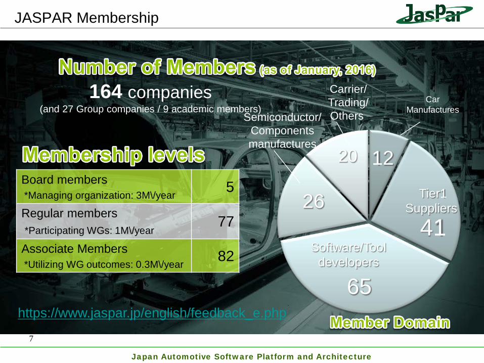
Car Manufactures
Tier1 Suppliers
Software/Tool developers
Semiconductor/ Components manufactures
Carrier/ Trading/ Others
12
41
65
26
20
164 companies (and 27 Group companies / 9 academic members)
Board members *Managing organization: 3M\/year
5
Regular members *Participating WGs: 1M\/year
77
Associate Members *Utilizing WG outcomes: 0.3M\/year
82
JASPAR Membership
7
https://www.jaspar.jp/english/feedback_e.php

Japan Automotive Software Platform and Architecture
OEM’s Suppliers Software/Tool Semiconductor/Component Others
12 41 65 26 20 [Board]
5 *Toyota *Nissan *Honda R&D
*Denso *Toyota Tsusho Electronics
[Regular]
77
*Suzuki *NSK *Alps *Showa *Stability *CATS *IBM *NXP *TDK *KDDI *Isuzu *Alpine *Jtekt *Yazaki *Fuji Soft *OTSL *FTL *Microchip *Toshiba *Toyota Cenral
R&D Labs *Mazda *Ricoh *Keihin *Advics *Omron AE *Systena *NEC *MegaChips *FHI(Subaru) *Panasonic *Clarion *Aisin Seiki *Hitachi ICS *ADaC *KPIT *Marvel Japan *Deroite
Tomatsu Risk Service
*Tokai Rika *Jatoko *Pioneer *Toyo Technica *ETAS *eSOL *Tyco Electronics *Fujitsu Ten *Bosch *Aisin AW *Vector Japan *Cadence *SCSK *Cypress *Hitachi AMS *Nissin Kogyo *MIC WARE *WITZ * Aubas *Renesas *DNP Co., *Nidec elesys *Nippon Seiki *Sunny Giken *Mentor Graphics *Murata
*Calsonic Kansei *Sumitomo Electric *Fujitsu BSC *Fujitsu *Hirose Electric *Akebono Brake *Mitsubishi Electric *Toshiba Information Systems *Toyota Industries *Furukawa Electric *Change Vision *Synopsys *Continental Automotive *Trend Micro
[Associate]
82
*Hyundai *KYB *Gaio *dSPACE *Eager *Infineon *Biz3 *Hino *Delphi *Ubiquitous *Mito Soft *AXE *Altera *Hosiden *Okaya *MMC *Fujikura *Mamezou *AI Corp. *USE *Hi-Lex *NTN *Ryosan *UD Trucks *Mitsuba *Elektrobit *ATS *Eiwa *Harman *Ryoden *Daihatsu *Transtron *Ixia *Xilinx *Ixia *Hitachi USLI *Sanshin
*Valeo Japan *NTT DATA MSE *ANRITSU *DIT *Lineer Technology *Hagiwara *Yamaha Motor *Fujitsu Systems West *ACCEL *ARM *Kyoei Sangyo
*NGK Spark Plug *Aisin Comcruise *Takasaki Kyodo *Analog Devices *TOMEN Elec. *Toyoda Gosei *Digital Contents *Tata Consultancy *Texas Instruments *Shinko Shoji *Toyo Denso *National Software *TTTech *Brison *THine Electronics *MACNICA *Magna International *Canon Software *Hitachi Hi-Tec *Sanden Automotive *Renesas
Easton *NEC Solution Innovators *HI CORP., *Yokoo *Yokogawa Meters & Instruments *Shin Dengen *NTT Docomo *Tokyo Electron Device *A&D *Alion *Secom *SHARP Business Software *Argus *Toppan
Copyright © 2017 JASPAR All rights reserved. 8
1-2. JASPAR Member List as of January, 2017

Japan Automotive Software Platform and Architecture
Executive Board Toyota, Nissan, Honda,
Toyota Tsusho Electronics
Steering Committee Board Members.
WG Chief
Functional Safety WG
Intellectual Property
WG
AUTOSAR Standardization
WG
Multimedia Architecture
WG
Mobile Device
Interface WG
Board Members Toyota, Nissan, Honda, Denso,
Toyota Tsusho Electronics
Administrator Toyota Tsusho Electronics
Auditor Toyota
Bluetooth Conformance
WG
Next Generation Hi-Speed
Network WG
In-vehicle LAN WG
Cyber Security
Technical WG
Cyber Security
Promotion WG
1-3. JASPAR Organization as of January, 2017
WG Leader:Nissan Sub Leader:Toyota
Japan Automotive Software Platform and Architecture
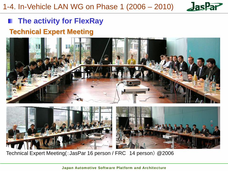
Technical Expert Meeting
Technical Expert Meeting(:JasPar 16 person / FRC 14 person) @2006
1-4. In-Vehicle LAN WG on Phase 1 (2006 – 2010)
The activity for FlexRay

Japan Automotive Software Platform and Architecture
2. In-Vehicle LAN WG on Phase 2 (2014 – 2015)
The activity for CAN-FD CAD FD Recommended Application Definitions Document This document defines network parameters, physical layers and the recommended
requirements for each application of CAN FD use case.
CAD FD Recommended Circuit Specifications This document formulates the recommended circuit specifications of the
communication circuit within the ECU that is connected to the CAN FD bus.
CAD FD Routing Evaluation Standards This document defines the evaluation standards used to determine routing
specifications of CAN FD network
CAD FD Recommended Routing Design Standard This document stipulates the recommended routing design standard of CAN FD
network system.
Japan Automotive Software Platform and Architecture
2-1. Recommended Application Definitions
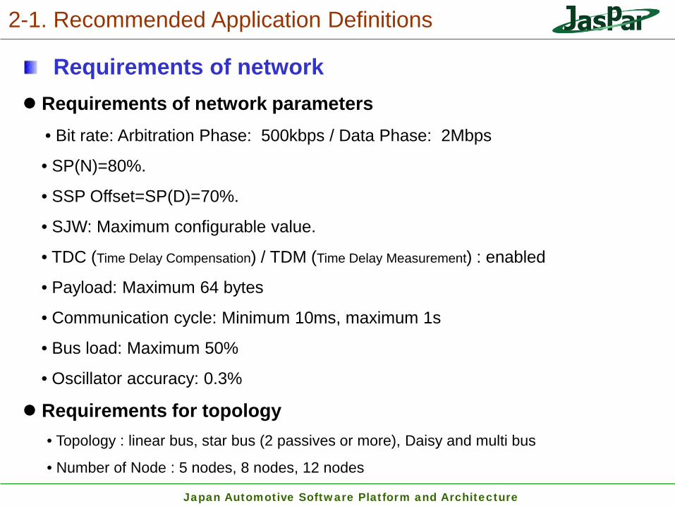
Requirements of network Requirements of network parameters • Bit rate: Arbitration Phase: 500kbps / Data Phase: 2Mbps
• SP(N)=80%.
• SSP Offset=SP(D)=70%.
• SJW: Maximum configurable value.
• TDC (Time Delay Compensation) / TDM (Time Delay Measurement) : enabled
• Payload: Maximum 64 bytes
• Communication cycle: Minimum 10ms, maximum 1s
• Bus load: Maximum 50%
• Oscillator accuracy: 0.3%
Requirements for topology • Topology : linear bus, star bus (2 passives or more), Daisy and multi bus
• Number of Node : 5 nodes, 8 nodes, 12 nodes

Japan Automotive Software Platform and Architecture
2-2. Recommended Circuit Specifications
Requirements of Circuit configurations • The description range of this document is indicated with dotted lines (---).
• The electric cable characteristics are equivalent to the JASPAR CAN FD
recommended routing design standards.
Japan Automotive Software Platform and Architecture
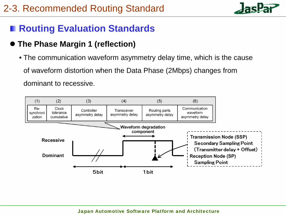
2-3. Recommended Routing Standard
Routing Evaluation Standards The Phase Margin 1 (reflection) • The communication waveform asymmetry delay time, which is the cause
of waveform distortion when the Data Phase (2Mbps) changes from
dominant to recessive.

Japan Automotive Software Platform and Architecture
2-3. Recommended Routing Standard
Routing Evaluation Standards The Phase Margin 1 (delay) • The routing delay time required for normal transmission and reception
between two nodes in the Arbitration Phase (500kbps).

Japan Automotive Software Platform and Architecture
2-3. Recommended Routing Standard
Routing Evaluation Standards The Phase Margin 2 • The communication waveform asymmetry delay time, which is the cause of
waveform distortion when the Data Phase (2Mbps) changes from recessive to
dominant.

Japan Automotive Software Platform and Architecture
2-3. Recommended Routing Standard
Recommended Routing Design Standard Bus-type routing design standard • Each bus-type network form’s recommended routing design standard
with the 5,8,12-nodes.

Japan Automotive Software Platform and Architecture
3. In-Vehicle LAN WG on Phase 2.5 (2016)
Improvement of topology flexibility for CAN-FD
WG Leader:Nissan Sub Leader:Toyota RSC routing design criteria Task Force
TF Leader:Denso
W/H Distortion Suppression Routing Design Standards Task Force
TF Leader:Yazaki
Members
Honda、Mazda、Hitachi AMS、Fujitsu Ten、Toukai Rika、Furukawa Electric、
Sumitomo Electoric、Murata、TDK
(2016 New Members)
Japan Automotive Software Platform and Architecture 16
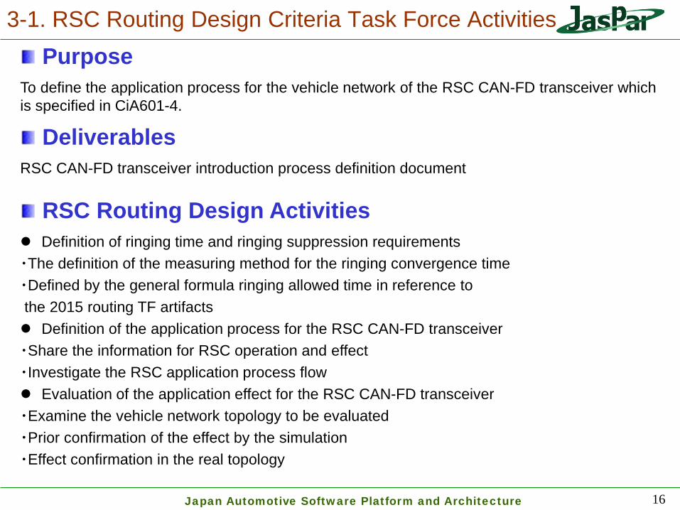
3-1. RSC Routing Design Criteria Task Force Activities Purpose
To define the application process for the vehicle network of the RSC CAN-FD transceiver which is specified in CiA601-4.
Deliverables RSC CAN-FD transceiver introduction process definition document
RSC Routing Design Activities Definition of ringing time and ringing suppression requirements ・The definition of the measuring method for the ringing convergence time ・Defined by the general formula ringing allowed time in reference to the 2015 routing TF artifacts Definition of the application process for the RSC CAN-FD transceiver ・Share the information for RSC operation and effect ・Investigate the RSC application process flow Evaluation of the application effect for the RSC CAN-FD transceiver ・Examine the vehicle network topology to be evaluated ・Prior confirmation of the effect by the simulation ・Effect confirmation in the real topology

Japan Automotive Software Platform and Architecture 17
3-3.RSC Routing Design Activities Definition of ringing time and ringing suppression requirements

Japan Automotive Software Platform and Architecture
3-2. Information for RSC Technology
18
The Principle
The main standard enactment item R; Matching impedance T; Control period (start, end)
Vdiff (CANH-CANL) 0V
2V
-2V
Impedance control OFF ON(120Ω)
ECU
Ringing generated by signal reflections repeat Reflection cause:Impedance mismatch in propagation path (Maximum reflection coefficient at the time of recessive)
Circuit Configuration
R T
Ringing waveform
CAN-H
CAN-L
State change
detection circuit
Switch control circuit
CAN-FD Transceiver ISO11898-2
Ringing suppression circuit
Impe dance
( Dominant → recessive )
Configuration as an optional feature (yellow part) to be added to the ISO11898-2 corresponding transceiver
Suppress the ringing to match the line-to-line impedance at the time of recessive change in the transceiver unit to prevent signal reflection
Suppress the reflected wave
Ideal waveform

Japan Automotive Software Platform and Architecture 19
Process flow
Definition of the application process for the RSC CAN-FD transceiver
3-3.RSC Routing Design Activities

Japan Automotive Software Platform and Architecture 20
Prior confirmation of the effect by the simulation Effect confirmation in the real topology
Evaluation of the application effect for the RSC CAN-FD transceiver
3-3.RSC Routing Design Activities

Japan Automotive Software Platform and Architecture
May 13 1st Kick-off, each company needs collecting, roles
June 3 2nd Deliberation of the definition ringing convergence time and ringing allowed time
July 1 3rd Sharing of inhibitory effect by RSC operation content and RSC Deliberation of the definition of the RSC application process (process flow)
Aug 5 4th Deliberation of the definition of the RSC application process (process flow) Deliberation of the application effect verification contents of the RSC equipped with transceivers (simulation)
Sep 2 5th Deliberation of the definition of the RSC application process (process flow) Deliberation of the simulation conditions of the RSC application examples
Oct 7 6th Definition document contents of deliberation , share simulation results of the RSC application examples
Nov 4 7th Definition document contents of deliberation, Actual evaluation result share of RSC application examples Dec 2 8th
Jan 13 9th
Feb 3 10th Review of defining document
Mar 3 11th Agreement of definition document
3-4. Work plan
21

Japan Automotive Software Platform and Architecture
Tx Rx
2.5m 2.5m
Rx
Purpose The purpose of this activity is to expand the routing flexibility of the CAN-FD by attaching a distortion suppression circuit to the W/H branch part. This is based on the results of the routing TF conducted on term 2015.
Deliverables CAN FD recommended routing design standards Ver.2.0(Updated)
Activity Contents (1)Consideration on the routing system requirements and the routing evaluation conditions. (2)Implementing the evaluation on the routing feasibility by taking in consideration the component tolerance of the distortion suppression circuit.
;Termination Circuit
;Distortion Suppression
Circuit
22
4. W/H Distortion Suppression Routing Design Standards Task Force Activities.
Phase Margin1(Reflection) Judgement Result
Unattached 434ns(NG) Attached 107ns(OK)
CANH
CANL
Attached Unattached

Japan Automotive Software Platform and Architecture
4-1. Consideration on The Routing System Requirements and The Routing Evaluation Conditions.
Simulation Evaluation Conditions The evaluation conditions are the same as the routing TF conducted on term 2015. Judgement Criteria;Phase Margin1(reflection)
(CAN-FD Routing Evaluation Standards compliant) Routing flexibility priority/Communication margin priority Transceiver Characteristics;typical/worst
Hardware Requirements.
ECU circuit components;worst value (CAN-FD Recommended Circuit Specifications compliant) Wires;worst value
Items Typical Worst
Differential Voltage 2.20V 3.00V
Rise Time(10-90%) 30.5ns 17.0ns
Fall Time(10-90%) 35.0ns 24.0ns
Measurement Circuit of Transceiver
Characteristics
Items Specified Value Characteristic Impedance 95~140Ω@1MHz
Propagation Delay 5.5ns/m以下@1MHz Conductor Resistance 25~210mΩ/m@DC
23

Japan Automotive Software Platform and Architecture
May 13 1st Discussion (required items for routing system and evaluation conditions etc.)
June 3 2nd Consideration on the routing system requirements and the routing evaluation conditions. ⇒ Review of inspection result for distortion suppression circuit element value for each number of stub for the star branch.
July 1 3rd Consideration on the routing system requirements and the routing evaluation conditions. ⇒ Phase Margin1(reflection) Worst form review used for evaluation.
Aug 5 4th Consideration on the routing system requirements and the routing evaluation conditions. ⇒ Phase Margin1(reflection)Evaluation results review.
Sep 2 5th Consideration on the routing system requirements and the routing evaluation conditions. ⇒ Discussion to reconsider the simulation evaluation conditions. ⇒Agreement completed.
Oct 7 6th Implementing the evaluation on the routing feasibility by taking in consideration the component tolerance of the distortion suppression circuit
Nov 4 7th
Dec 2 8th
Jan 13 9th
Feb 3 10th CAN FD Recommended Routing Design Standards Ver.2.0 Review
Mar 3 11th CAN FD Recommended Routing Design Standards Ver.2.0 Agreement
24
4-2. work plan
Japan Automotive Software Platform and Architecture
Thank you


