274
JCM-350-E01/E02 Controller with I/O module 60878384

JCM-350-E01/E02
Controller with I/O module
60878384

2 Jetter AG
Introduction
Variant: Jetter Item number: 60878384 Revision 1.12.2 December 2013 / Printed in Germany This document has been compiled by Jetter AG with due diligence, and based on the known state of the art. In the case of modifications, further developments or enhancements to products shipped in the past, a revised document will be supplied only if required by law, or deemed appropriate by Jetter AG. Jetter AG shall not be liable for errors in form or content, or for missing updates, as well as for damages or disadvantages resulting from such failure. The logos, brand names, and product names mentioned in this document are trade marks or registered trade marks of Jetter AG, of associated companies or other title owners and must not be used without consent of the respective title owner.

Jetter AG 3
JCM-350-E01/E02 Introduction
How to contact us:
Jetter AG
Graeterstrasse 2
71642 Ludwigsburg
Germany
Phone - Switchboard: +49 7141 2550-0
Phone - Sales: +49 7141 2550-433
Phone - Technical Hotline: +49 7141 2550-444
Fax - Sales: +49 7141 2550-484
E-mail - Sales: [email protected]
E-mail - Technical Hotline: [email protected]
This user manual is an integral part of JCM-350-E01/E02:
Type:
Serial #:
Year of manufacture:
Order #:
To be entered by the customer:
Inventory #:
Place of operation:
Address
Assignment to product

4 Jetter AG
Introduction
This document is an integral part of the JCM-350-E01/E02:
Keep this document in a way that it is always at hand until the JCM-350-E01/E02 will be disposed of.
Pass this document on, if the JCM-350-E01/E02 is sold or loaned/leased out.
In any case you encounter difficulties to clearly understand this document, please contact Jetter AG. Jetter AG would appreciate any suggestions and contributions on your part and would ask you to contact Jetter AG at the following e-mail address: [email protected]. This will help the documentation department produce documents that are more user-friendly, as well as address your wishes and requirements. This document contains important information on the following topics:
Transport Mounting Installation Programming Operation Maintenance Repair Therefore, the user must carefully read, understand and observe this document and especially the safety instructions. In the case of missing or inadequate knowledge of this document, Jetter AG shall be exempted from any liability. Therefore, the operating company is recommended to obtain the persons' confirmation in writing that they have read and understood this document.
Significance of this user manual

Jetter AG 5
JCM-350-E01/E02 Introduction
Hazard levels
This topic describes the safety labels and hazard levels used in this manual.
Signs using this symbol are to warn you of injuries or even death. Follow the instructions given in the corresponding topic to prevent hazards.
Safety information is classified into the following hazard levels:
Hazard level Consequences Probability
DANGER Death/severe injury (irreversible) The hazard is imminent.
WARNING Death/severe injury (irreversible) Potential occurrence
CAUTION Slight injury (reversible) Potential occurrence
CAUTION Material damage Potential occurrence
Introduction
Safety labels
Hazard levels


Jetter AG 7
JCM-350-E01/E02 Contents
Table of Contents
Hazard levels ................................................................................................................................. 5
1 Safety Instructions 11
Basic safety instructions .............................................................................................................. 12 Residual dangers and protective measures ................................................................................ 14
2 Product description and equipment configuration 15
JCM-350-E01/E02 - Product description and design................................................................... 16 Parts and interfaces ..................................................................................................................... 19 Order Reference / Options ........................................................................................................... 22 Physical dimensions .................................................................................................................... 23
3 Identifying the Controller 25
3.1 Identification by means of the nameplate ............................................................................... 26 Nameplate .................................................................................................................................... 27
3.2 Identification via CANopen® Bus ............................................................................................. 28 EDS registers of a controller ........................................................................................................ 29 Retrieving EDS data from the I/O module.................................................................................... 31 Example: Retrieving EDS data .................................................................................................... 33 EDS and software version of the module..................................................................................... 35
3.3 Version Registers ....................................................................................................................... 36 Hardware revision numbers ......................................................................................................... 37 Version numbers of software running in the device ..................................................................... 39
4 Mounting and installation 41
4.1 Installing the controller JCM-350-E01/E02 .............................................................................. 42 Installation .................................................................................................................................... 43
4.2 Wiring .......................................................................................................................................... 47 Wiring principle............................................................................................................................. 48
4.2.1 JCM-350-E01/E02 - Power supply ............................................................................................ 50 Connecting the supply voltage to X118/X218 .............................................................................. 51 Connecting the supply voltage to X119/X219 .............................................................................. 53 Sensor supply voltage .................................................................................................................. 56
4.2.2 Connecting peripheral devices to the JCM-350-E01/E02 ....................................................... 58 Connecting analog inputs ............................................................................................................ 59 Connecting analog outputs .......................................................................................................... 61 CAN interfaces - Connection ....................................................................................................... 63 Connecting digital frequency/pulse inputs ................................................................................... 65 Connecting digital inputs .............................................................................................................. 67 Connecting digital outputs ............................................................................................................ 70 Connecting H-bridges .................................................................................................................. 73 Connecting PWM outputs ............................................................................................................ 75 Connecting relays ........................................................................................................................ 78
4.2.3 JCM-350-E01/E02 - I²t monitoring ............................................................................................. 81 Retrieving I²t monitoring data ....................................................................................................... 82 Digital outputs - I²t monitoring of H-bridges and power supply .................................................... 84 I²t monitoring of digital outputs ..................................................................................................... 87

8 Jetter AG
Contents
5 Initial commissioning 89
Preparatory work for initial commissioning .................................................................................. 90 Initial Commissioning in JetSym ................................................................................................. 92 Enabling the device in the application program .......................................................................... 98
6 CANopen® STX API 99
STX Function CanOpenInit ....................................................................................................... 101 STX Function CanOpenSetCommand ...................................................................................... 103 STX Function CanOpenUploadSDO ......................................................................................... 106 STX Function CanOpenDownloadSDO ..................................................................................... 111 STX function CanOpenAddPDORx ............................................................................................ 116 STX Function CanOpenAddPDOTx .......................................................................................... 123 Heartbeat monitoring ................................................................................................................. 130 CANopen® object dictionary for JCM-350-E01/E02 ................................................................. 134
7 SAE J1939 STX API 139
Content of a J1939 Message .................................................................................................... 140 STX Function SAEJ1939Init ...................................................................................................... 142 STX Function SAEJ1939SetSA ................................................................................................ 144 STX Function SAEJ1939GetSA ................................................................................................ 145 STX Function SAEJ1939AddRx ................................................................................................ 146 STX Function SAEJ1939AddTx ................................................................................................ 149 STX Function SAEJ1939RequestPGN ..................................................................................... 152 STX Function SAEJ1939GetDM1 ............................................................................................. 155 STX Function SAEJ1939GetDM2 ............................................................................................. 158 STX Function SAEJ1939SetSPNConversion ........................................................................... 161 STX Function SAEJ1939GetSPNConversion ........................................................................... 163
8 Programming the JCM-350-E01/E02 165
Abbreviations, module register properties and formats ............................................................ 167 8.1 Programming the device ........................................................................................................ 168
Overview of Registers: JCM-350-E01/E02 - Status and instructions ........................................ 169 8.2 Programming the operator panel........................................................................................... 176
Operator panel: Programming, variant 1 ................................................................................... 177 Description of Registers: Operator panel, variant 1 .................................................................. 178 Operator panel: Programming, variant 2 ................................................................................... 182 Description of Registers: Operator panel, variant 2 .................................................................. 183
8.3 Programming digital inputs and outputs .............................................................................. 186 8.3.1 Digital output 1 ... 8 ................................................................................................................. 187
Registers for monitoring digital values ...................................................................................... 188 Registers for digital value output ............................................................................................... 192
8.3.2 Digital input 1 ... 11 .................................................................................................................. 194 Switching a digital input: Active-low or active-high. ................................................................... 195 Registers for retrieving digital values ........................................................................................ 197 Registers for retrieving analog values as digital values ............................................................ 198
8.3.3 Digital input 12 ... 15 (frequency input) ................................................................................. 201 Description of Registers: Retrieving frequency inputs .............................................................. 202
8.3.4 Frequency measurement ........................................................................................................ 204 Description of Registers: Frequency measurement .................................................................. 206
8.3.5 PWM outputs 1 ... 8 ................................................................................................................. 210 Description of Registers: PWM outputs 1 ... 8 ........................................................................... 211
Jetter AG 9
JCM-350-E01/E02 Contents
8.3.6 Relay outputs 1 ... 4 ................................................................................................................. 214 Description of Registers: Relay outputs 1 ... 4 ........................................................................... 215
8.3.7 H-bridges 1 ... 2 ........................................................................................................................ 216 Description of Registers: H-bridge ............................................................................................. 217
8.4 Programming analog inputs and outputs .............................................................................. 222 8.4.1 A/D converter - Converting electrical signals into digital values ....................................... 223
Converting analog voltages into digital values ........................................................................... 224 Configuring A/D conversion for several measuring ranges ....................................................... 225 Description of Registers: Converting analog values into digital values ..................................... 226 Description of Registers: Analog current/voltage values ........................................................... 228
8.4.2 D/A conversion - Converting digital values into electrical signals ..................................... 229 Digital/analog conversion ........................................................................................................... 230 Registers for digital-to-analog conversion ................................................................................. 231
9 Betriebssystemupdate 233
9.1 Updating the Operating System of the Controller ................................................................ 234 OS update by means of JetSym ................................................................................................ 235
10 Quick reference - JCM-350 237
11 Quick reference - JCM-350-E01/E02, I/O module 241
Appendix 244
A: JCM-350-E01/E02 - Pin assignment ....................................................................................... 245 Connector X110 - Pin assignment ............................................................................................. 246 Connector X118 - Pin assignment ............................................................................................. 248 Connector X119 - Pin assignment ............................................................................................. 250 Connector X210 - Pin assignment ............................................................................................. 253 Connector X218 - Pin assignment ............................................................................................. 255 Connector X219 - Pin assignment ............................................................................................. 258
B: Technical Data .......................................................................................................................... 261 Technical specifications ............................................................................................................. 262 Physical dimensions .................................................................................................................. 268 Operating parameters - Environment and mechanics ............................................................... 270 Operating Parameters - EMC .................................................................................................... 271
C: Index .......................................................................................................................................... 272


Jetter AG 11
JCM-350-E01/E02 Safety Instructions
1 Safety Instructions
This chapter informs the user of fundamental safety instructions. It also warns the user of residual dangers, if applicable.
Topic Page Basic safety instructions ............................................................................... 12 Residual dangers and protective measures ................................................. 14
Introduction
Contents

12 Jetter AG
1 Safety Instructions
Basic safety instructions
This device complies with the valid safety regulations and standards. Jetter AG attaches great importance to the safety of the users. Of course, the user should adhere to the following regulations:
Relevant accident prevention regulations; Accepted safety rules; EC guidelines and other country-specific regulations
Usage according to the intended conditions of use implies operation in accordance with this user manual. This device has been designed as a controller for use in commercial vehicles and mobile machines, such as
Road sweepers Fire-fighting vehicles Harvesting machines Construction machines
The controller JCM-350-E01/E02 meets the requirements of the European Automotive EMC Directive for electric/electronic subassemblies. The controller JCM-350-E01/E02 is intended for installation in a mobile machine. Operate the controller JCM-350-E01/E02 only within the limits and conditions set forth in the technical specifications. The operating voltage of the controller JCM-350-E01/E02 is classified as SELV (Safety Extra Low Voltage). Therefore, the JCM-350-E01/E02 controller is not subject to the EU Low Voltage Directive.
This device must not be used in technical systems which to a high degree have to be fail-safe, e. g. ropeways and aeroplanes. The JCM-350-E01/E02 is no safety-related part as per Machinery Directive 2006/42/EC. This device is not qualified for safety-relevant applications and must, therefore, NOT be used to protect persons. If you intend to operate the device at ambient conditions not being in conformity with the permitted operating conditions, please contact Jetter AG beforehand.
Depending on the life cycle of the product, the persons involved must possess different qualifications. The following requirements must be met, in order to grant safety in handling the device in each phase of the product life cycle.
Product Life Cycle Minimum Qualification
Transport/Storage: Trained and instructed personnel with knowledge in handling electrostatically sensitive components.
Mounting/Installation: Specialized personnel with training in electrical/automotive engineering, such as automotive mechatronics fitters.
Introduction
Intended conditions of use
Usage other than intended
Personnel qualification
Jetter AG 13
JCM-350-E01/E02 Safety Instructions
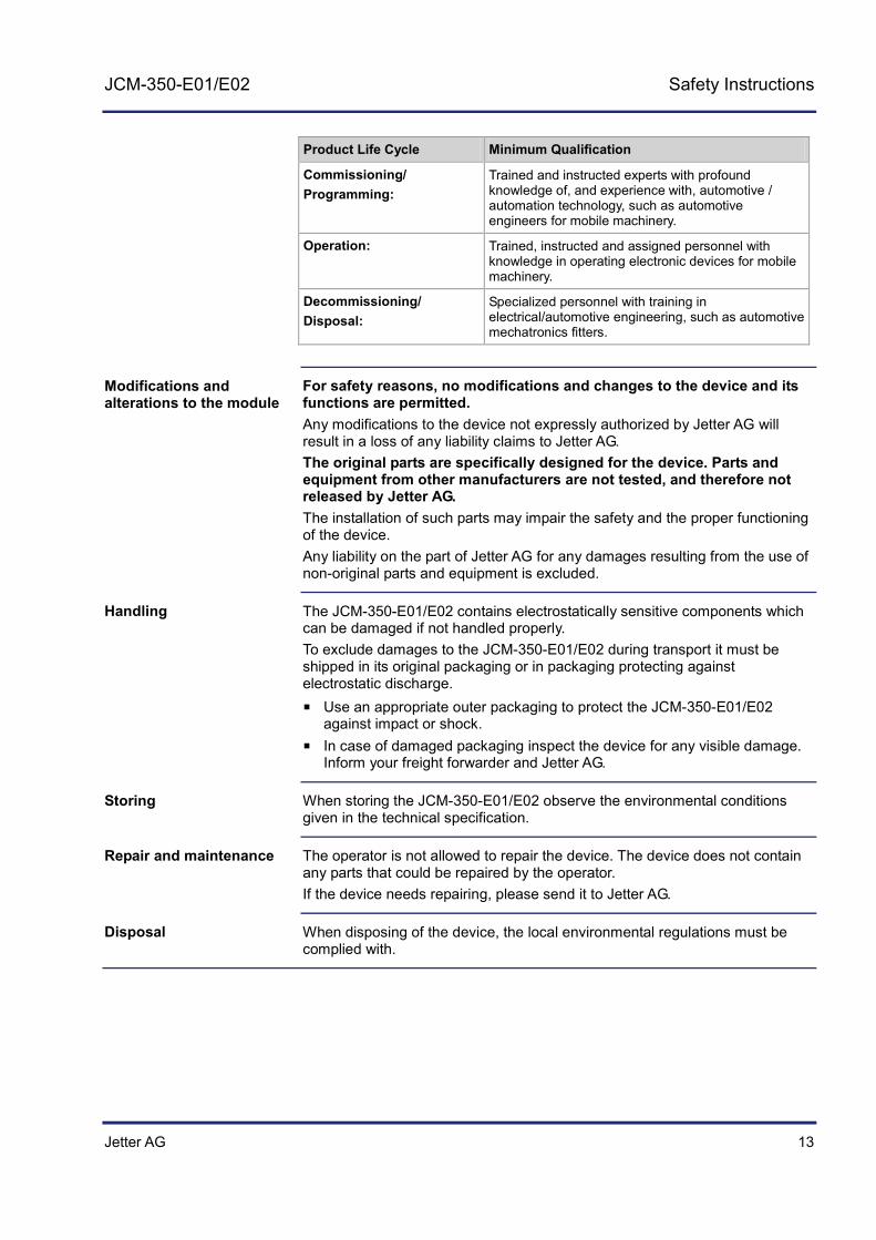
Product Life Cycle Minimum Qualification
Commissioning/ Programming:
Trained and instructed experts with profound knowledge of, and experience with, automotive / automation technology, such as automotive engineers for mobile machinery.
Operation: Trained, instructed and assigned personnel with knowledge in operating electronic devices for mobile machinery.
Decommissioning/ Disposal:
Specialized personnel with training in electrical/automotive engineering, such as automotive mechatronics fitters.
For safety reasons, no modifications and changes to the device and its functions are permitted. Any modifications to the device not expressly authorized by Jetter AG will result in a loss of any liability claims to Jetter AG. The original parts are specifically designed for the device. Parts and equipment from other manufacturers are not tested, and therefore not released by Jetter AG. The installation of such parts may impair the safety and the proper functioning of the device. Any liability on the part of Jetter AG for any damages resulting from the use of non-original parts and equipment is excluded.
The JCM-350-E01/E02 contains electrostatically sensitive components which can be damaged if not handled properly. To exclude damages to the JCM-350-E01/E02 during transport it must be shipped in its original packaging or in packaging protecting against electrostatic discharge.
Use an appropriate outer packaging to protect the JCM-350-E01/E02 against impact or shock.
In case of damaged packaging inspect the device for any visible damage. Inform your freight forwarder and Jetter AG.
When storing the JCM-350-E01/E02 observe the environmental conditions given in the technical specification.
The operator is not allowed to repair the device. The device does not contain any parts that could be repaired by the operator. If the device needs repairing, please send it to Jetter AG.
When disposing of the device, the local environmental regulations must be complied with.
Modifications and alterations to the module
Handling
Storing
Repair and maintenance
Disposal

14 Jetter AG
1 Safety Instructions
Residual dangers and protective measures
Consider the residual dangers mentioned in this chapter when assessing the risks associated with your machine.
DANGER
Hazard in explosive gas atmosphere!
This device can become a source of ignition in potentially explosive atmospheres.
Do not use this device in potentially explosive atmospheres.
WARNING
Hot surface hazard!
The JCM-350-E01/E02 can heat up during operation. During operation the surface temperature of this device will become hot enough (> 60 ) to cause burns.
Take protective measures to prevent inadvertent contact with the device, e.g. install protective covers.
Allow the device to cool down for some time before you start working on it, e.g. to carry out maintenance jobs.
CAUTION
Possible occurrence of malfunctions!
CAN wires which have not been twisted may increase susceptibility to noise. This may disturb communications with the device which, in turn, may cause malfunctions.
Make sure that twisted pair cables are used for connecting the CAN interfaces.
Residual dangers

Jetter AG 15
JCM-350-E01/E02 Product description and equipment configuration
2 Product description and equipment configuration
This chapter covers the design of the device, as well as how the order reference is made up including all options.
Topic Page JCM-350-E01/E02 - Product description and design ................................... 16 Parts and interfaces ...................................................................................... 19 Order Reference / Options ........................................................................... 22 Physical dimensions ..................................................................................... 23
Introduction
Contents

16 Jetter AG
2 Product description and equipment configuration
JCM-350-E01/E02 - Product description and design
The JCM-350-E01/E02 is a controller equipped with a built-in I/O module and has been designed for use in the harsh environment of trucks. The controller JCM-350-E01/E02 is available in two models:
The controller JCM-350-E01 is equipped with one built-in I/O module. The controller JCM-350-E02 is equipped with two built-in I/O modules.
The features of the controller JCM-350-E01 are listed below:
4 analog inputs, 12 bits, configurable
0 V ... +10 V
0 V ... +32 V
0 mA ... 20 mA
4 mA ... 20 mA
Ratiometric voltage measurement (related to operating voltage)
11 digital active-high/active-low inputs, configurable
4 digital frequency inputs
8 PWM outputs
4 analog outputs
8 digital PNP outputs 2 H-bridges
2 relay contacts 15 A
2 relay contacts 2 A
5 CAN-2.0B interfaces; CAN1: CANopen® device, CAN2 ... CAN5: J1939 or CANopen® device selectable
8 function keys with LED
3 mode LEDs (RUN/CONFIG/TEACH)
RAM memory: 32 KB (remanent)
Flash memory: 128 MB
System memory: 256 MB
Controller JCM-350-E01/E02
Product features - JCM-350-E01

Jetter AG 17
JCM-350-E01/E02 Product description and equipment configuration
The features of the controller JCM-350-E02 are listed below:
8 analog inputs, 12 bits, configurable
0 V ... +10 V
0 V ... +32 V
0 mA ... 20 mA
4 mA ... 20 mA
Ratiometric voltage measurement (related to operating voltage)
22 digital active-high/active-low inputs, configurable
8 digital frequency inputs
16 PWM outputs
8 analog outputs
16 digital PNP outputs 4 H-bridges
4 relay contacts 15 A
4 relay contacts 2 A
5 CAN-2.0B interfaces; CAN1: CANopen® device, CAN2 ... CAN5: J1939 or CANopen® device selectable
8 function keys with LED
3 mode LEDs (RUN/CONFIG/TEACH)
32 KB RAM (remanent)
Flash memory: 128 MB
System memory: 256 MB
Product features - JCM-350-E02

18 Jetter AG
2 Product description and equipment configuration
The JCM-350-E01/E02 is available in two different operator panel designs. The functionality is not affected by the different designs.
F1
F2
F3
F4
F5
F6
F7
F8
MODE
CAN 5
FAILURE
SUPPLY
NODE
CAN 4
CAN 3
CAN 2
CAN 1
RUN TEACHCONFIG
F1
F2
F3
F4
F5
F6
F7
F8
MODE
FAILURE
SUPPLY
NODE
CAN 3
CAN 2
CAN 1
CAN 5 /
CAN 4 /
RUN TEACHCONFIG
1 2
Number Description
1 The mode LEDs are dual-color LEDs (red/green)
2 The status LEDs are single-colored. Status LEDs "Supply" and "Failure" are red, the other status LEDs are green.
Different operator panel designs

Jetter AG 19
JCM-350-E01/E02 Product description and equipment configuration
Parts and interfaces
This chapter describes the parts and interfaces of the JCM-350-E01/E02.
The following JCM-350 models are available:
JCM-350-E01 - controller with one built-in I/O module JCM-350-E01 - controller with two built-in I/O modules
The illustration below shows the two models:
79
JCM-350-E01
JCM-350-E02JCM-350-E01 &
JCM-350-E02
One side wall of the JCM-350-E01 is provided with three connectors for connecting peripheral devices. The opposite side wall is not equipped with connectors. The JCM-350-E02 is provided with three connectors on each side wall.
Introduction
Models - overview

20 Jetter AG
2 Product description and equipment configuration
The JCM-350-E01/E02 features the following parts and interfaces:
12
3
4
5
6
7
Number Element Description
1 Nameplate Lets you identify the JCM-350-E01/E02
2 Operator panel Lets you directly operate the controller
3 X210, X218 and X219 Only with JCM-350-E02: Lets you connect additional peripherals and power supply
4 Pressure compensation membrane
Compensation of inside and outside air pressure
5 6 fastening lugs For screwing down the JCM-350-E01/E02
6 CAN interface Allows communication with other CAN devices
7 X110, X118 and X119 Lets you connect additional peripherals and power supply
Parts and interfaces

Jetter AG 21
JCM-350-E01/E02 Product description and equipment configuration
The operator panel lets you access the controller JCM-350 to set, for example, its node ID.
Number Element Description
1 Mode Function key for configuring the controller
2 Mode LED Indicates the mode (RUN, CONFIG and TEACH)
3 Status LED Indicates the controller condition
4 F1 through F8 Function keys for triggering certain controller functions.
Operator panel
22 Jetter AG
2 Product description and equipment configuration
Order Reference / Options
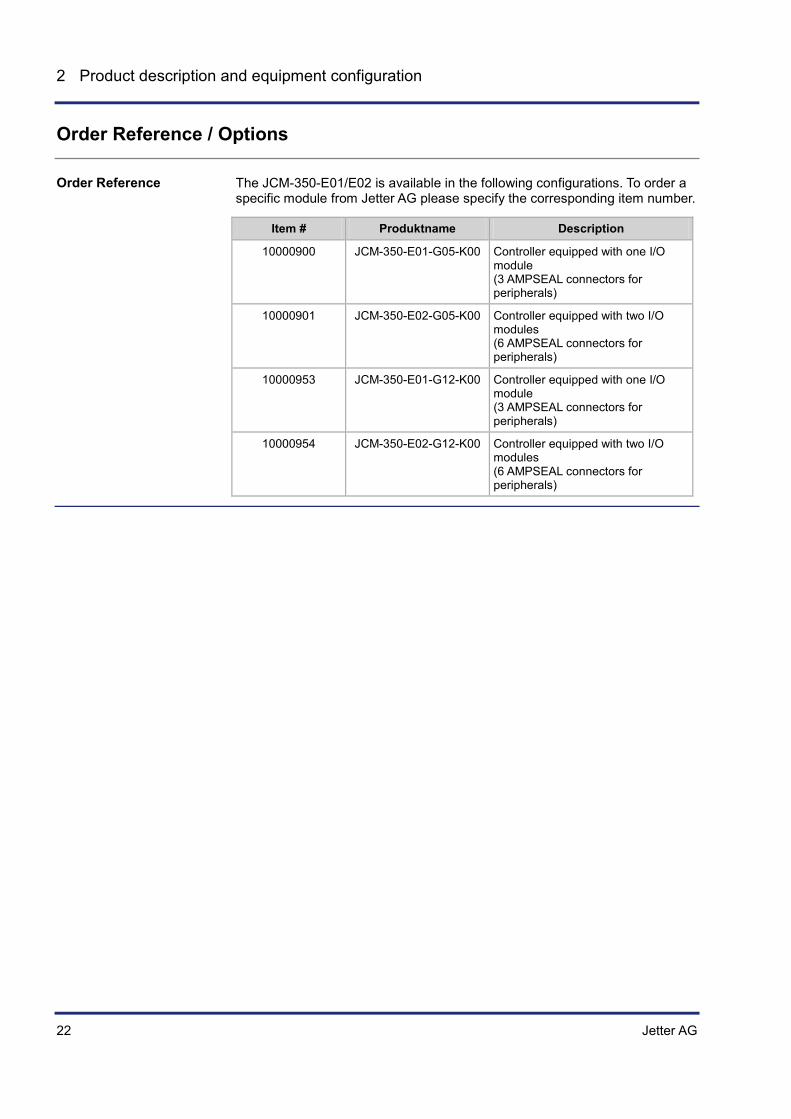
The JCM-350-E01/E02 is available in the following configurations. To order a specific module from Jetter AG please specify the corresponding item number.
Item # Produktname Description
10000900 JCM-350-E01-G05-K00 Controller equipped with one I/O module (3 AMPSEAL connectors for peripherals)
10000901 JCM-350-E02-G05-K00 Controller equipped with two I/O modules (6 AMPSEAL connectors for peripherals)
10000953 JCM-350-E01-G12-K00 Controller equipped with one I/O module (3 AMPSEAL connectors for peripherals)
10000954 JCM-350-E02-G12-K00 Controller equipped with two I/O modules (6 AMPSEAL connectors for peripherals)
Order Reference

Jetter AG 23
JCM-350-E01/E02 Product description and equipment configuration
Physical dimensions
This chapter details the physical dimensions of the JCM-350-E01/E02 and the conditions for its installation. This device is available from Jetter AG in two different housing designs: G05 or G12.
The illustration below shows the dimensions of the model G05:
Introduction
Model G05
24 Jetter AG
2 Product description and equipment configuration
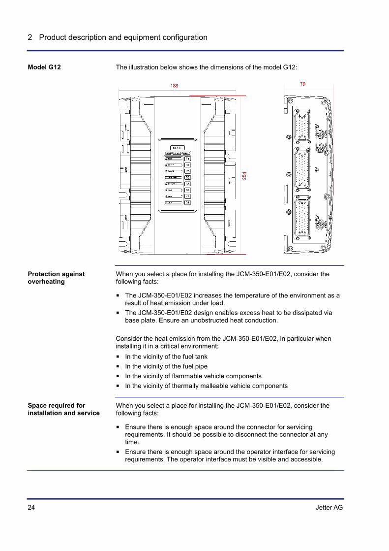
The illustration below shows the dimensions of the model G12:
When you select a place for installing the JCM-350-E01/E02, consider the following facts:
The JCM-350-E01/E02 increases the temperature of the environment as a result of heat emission under load.
The JCM-350-E01/E02 design enables excess heat to be dissipated via base plate. Ensure an unobstructed heat conduction.
Consider the heat emission from the JCM-350-E01/E02, in particular when installing it in a critical environment:
In the vicinity of the fuel tank In the vicinity of the fuel pipe In the vicinity of flammable vehicle components In the vicinity of thermally malleable vehicle components
When you select a place for installing the JCM-350-E01/E02, consider the following facts:
Ensure there is enough space around the connector for servicing requirements. It should be possible to disconnect the connector at any time.
Ensure there is enough space around the operator interface for servicing requirements. The operator interface must be visible and accessible.
Model G12
Protection against overheating
Space required for installation and service

Jetter AG 25
JCM-350-E01/E02 Identifying the Controller
3 Identifying the Controller
This chapter is for supporting you in identifying the following information with regard to JCM-350-E01/E02:
Determining the hardware revision. Determining the OS version of the controller and its software components. Retrieving Electronic Data Sheet (EDS) information. Numerous
production-relevant data are permanently stored in the EDS.
To be able to identify the JCM-350-E01/E02 controller, the following prerequisites must be fulfilled:
The controller is connected to a PC. The programming tool JetSym 4.3 or higher is installed on the PC (earlier
versions do not support STX).
If you wish to contact the hotline of Jetter AG in case of a problem, please have the following information on the JCM-350-E01/E02 controller ready:
Serial number OS version number of the controller Hardware revision
Topic Page Identification by means of the nameplate ..................................................... 26 Identification via CANopen® Bus ................................................................. 28 Version Registers.......................................................................................... 36
Purpose of this chapter
Prerequisites
Information for hotline requests
Contents

26 Jetter AG
3 Identifying the Controller
3.1 Identification by means of the nameplate
The nameplate is attached to the housing of the JCM-350-E01/E02 and contains details, such as hardware revision number and serial number. If you wish to contact the hotline of Jetter AG in case of a problem, please have this information ready.
Topic Page Nameplate ..................................................................................................... 27
Introduction
Contents

Jetter AG 27
JCM-350-E01/E02 Identifying the Controller
Nameplate
The nameplate of a JCM-350-E01/E02 contains the following information:
1 2
3
456
Number Description
1 Controller model and module type
2 Serial number
3 Item number
4 Certification mark (e1) with registration number for automotive applications
5 Hardware revision
6 Power supply - Technical specifications
Nameplate

28 Jetter AG
3 Identifying the Controller
3.2 Identification via CANopen® Bus
The JCM-350-E01/E02 features an electronic data sheet (EDS). Numerous production-relevant data are permanently stored in the EDS. EDS data can be retrieved via CANopen® bus. The following EDS are available:
EDS of the controller JCM-350 EDS of I/O modules
Topic Page EDS registers of a controller ......................................................................... 29 Retrieving EDS data from the I/O module .................................................... 31 Example: Retrieving EDS data ..................................................................... 33 EDS and software version of the module ..................................................... 35
Introduction
Contents

Jetter AG 29
JCM-350-E01/E02 Identifying the Controller
EDS registers of a controller
EDS registers let you read the entries in the Electronic Data Sheet (EDS) of the controller.
The basic register number is dependent on the controller. The register number is calculated by adding the number of the module register (MR) and the basic register number.
Controller Basic register number Register numbers
JCM-350 100000 100500 ... 100999
The following table lists the EDS registers of a controller, as well as their connection to the entries in the EDS file "/System/eds.ini". As there is only one register set, select the required module via module registers 500 and 501. The contents of the selected EDS are then displayed in the following registers.
Registers Section in eds.ini Name in eds.ini
Description
MR 500 - - Functional group: 0 Controller
MR 501 - - Module number (if MR 500 > 0)
MR 600 IDENTIFICATION Revision Version of this section
MR 601 Code Module code
MR 602 to MR 612
Name Module name or controller name
MR 613 PcbRev Hardware revision
MR 614 PcbOpt Hardware revision
MR 700 PRODUCTION Revision Version of this section
MR 701 to MR 707
SerNum Serial number
MR 708 Day Production date: Day
MR 709 Month Production date: Month
MR 710 Year Production date: Year
MR 711 TestNum Internal usage
MR 712 TestRev Internal usage
MR 800 FEATURES Revision Version of this section
MR 801 MAC Addr MAC address (manufacturer section)
MR 802 MAC Addr MAC address (device section)
MR 803 Serial interface
Serial interface is available
MR 804 Switch S11 Internal usage
MR 805 STX Runtime environment for application program
Introduction
Register numbers
EDS Registers of a Controller

30 Jetter AG
3 Identifying the Controller
Registers Section in eds.ini Name in eds.ini
Description
MR 806 NVRegs Number of remanent registers

Jetter AG 31
JCM-350-E01/E02 Identifying the Controller
Retrieving EDS data from the I/O module
EDS registers on the I/O module let you read the entries in the Electronic Data Sheet (EDS). Numerous production-relevant data are permanently stored in the EDS.
EDS data can be read out of the following registers:
Registers Description
R 600y99080 Selecting a module
R 600y99081 Selecting EDS page 0 or 1 The EDS register "Selecting a module" has been implemented for compatibility reasons. For the JCM-350-E01/E02 this register is completely irrelevant. You can have displayed only one EDS page at a time. The registers of EDS page 0 and EDS page 1 are overlaid registers. If you simultaneously open both EDS pages in the JetSym setup window, the inactive EDS page does not display relevant data.
To be able to read out EDS page 0, special register 600y99081 must contain value 0. EDS page 0 contains the following production-related data:
Registers Type Description
R 600y99082 int Revision of EDS page 0
R 600y99083 int Module code
R 600y99084 string Module name
R 600y99095 int Hardware revision
R 600y99096 int Hardware revision
R 600y99097 int Minimum OS version required to match the given hardware
To be able to read out EDS page 1, special register 600y99081 must contain value 1. EDS page 1 contains the following production-related data:
Registers Type Description
R 600y99082 int Revision of EDS page 1
R 600y99083 string Serial number
R 600y99090 int Production date: Day
R 600y99091 int Production date: Month
R 600y99092 int Production date: Year
R 600y99093 int Assembly test number
R 600y99094 int Assembly test revision
Introduction
Registers - Overview
Contents of EDS page 0
Contents of EDS page 1

32 Jetter AG
3 Identifying the Controller
To retrieve EDS information, proceed as follows:
Step Action
1 Select the EDS page to be retrieved:
If ... ... then ...
... you wish to read EDS page 0, ... enter 0 into register R 600y99081.
... you wish to read EDS page 1, ... enter 1 into register R 600y99081.
2 Retrieve the information from the selected EDS page via registern R 600y99082 ... R 600y99094.
Retrieving EDS information

Jetter AG 33
JCM-350-E01/E02 Identifying the Controller
Example: Retrieving EDS data
EDS data of I/O modules on the JCM-350-E01/E02 are to be displayed in the JetSym setup window.
Declare the EDS registers as variables in a JetSym application program. The variables are then entered into the setup window. R 600y99081 lets you toggle between EDS pages.
JetSym is installed on a PC and the JCM-350-E01/E02 is connected to this PC via CANopen® adaptor.
This sample program has been tested with the following software versions:
JetSym version 5.1.0 Controller JCM-350, OS version 1.12.0.06 For other sample programs, refer to JetSym online help.
Type
// Defining the interface and device number JCM_350_E01_2_EDS:
Struct
// not required - but must be defined Module : Int;
// Selecting the page Page : Int;
End_Struct;
// Defining EDS page 0 JCM_350_E01_2_EDS_PAGE0:
Struct
Version : Int;
Code : Int;
ModuleName : RegString[31];
PCB_REV : Int;
PCB_Opt : Int;
OSVersionMin : Int;
End_Struct;
// Defining EDS page 1 JCM_350_E01_2_EDS_PAGE1:
Struct
Version : Int;
Sernum : RegString[19];
TS_Day : Int;
TS_Month : Int;
TS_Year : Int;
TestNum : Int;
TestRev : Int;
Task
Solution
Prerequisites
Software versions
JetSym STX program

34 Jetter AG
3 Identifying the Controller
End_Struct;
End_Type;
Var
EDS : JCM_350_E01_2_EDS At %VL 600199080;
Page : Int At %VL 600199081;
EDS0 : JCM_350_E01_2_EDS_PAGE0 At %VL 600199082;
EDS1 : JCM_350_E01_2_EDS_PAGE1 At %VL 600199082;
End_Var;
Jetter AG 35
JCM-350-E01/E02 Identifying the Controller
EDS and software version of the module
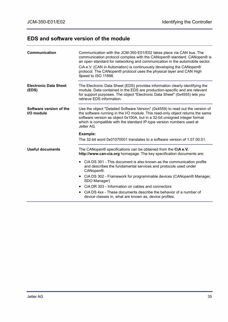
Communication with the JCM-350-E01/E02 takes place via CAN bus. The communication protocol complies with the CANopen® standard. CANopen® is an open standard for networking and communication in the automobile sector. CiA e.V. (CAN in Automation) is continuously developing the CANopen® protocol. The CANopen® protocol uses the physical layer and CAN High Speed to ISO 11898.
The Electronic Data Sheet (EDS) provides information clearly identifying the module. Data contained in the EDS are production-specific and are relevant for support purposes. The object "Electronic Data Sheet" (0x4555) lets you retrieve EDS information.
Use the object "Detailed Software Version" (0x4559) to read out the version of the software running in the I/O module. This read-only object returns the same software version as object 0x100A, but in a 32-bit unsigned integer format which is compatible with the standard IP-type version numbers used at Jetter AG.
Example: The 32-bit word 0x01070001 translates to a software version of 1.07.00.01.
The CANopen® specifications can be obtained from the CiA e.V. http://www.can-cia.org homepage. The key specification documents are:
CiA DS 301 - This document is also known as the communication profile and describes the fundamental services and protocols used under CANopen®.
CiA DS 302 - Framework for programmable devices (CANopen® Manager, SDO Manager)
CiA DR 303 - Information on cables and connectors CiA DS 4xx - These documents describe the behavior of a number of
device classes in, what are known as, device profiles.
Communication
Electronic Data Sheet (EDS)
Software version of the I/O module
Useful documents

36 Jetter AG
3 Identifying the Controller
3.3 Version Registers
The operating system of the JCM-350-E01/E02 provides several registers which let you read out the version numbers of the OS and its components. If you wish to contact the hotline of Jetter AG in case of a problem, please have this information ready.
Topic Page Hardware revision numbers .......................................................................... 37 Version numbers of software running in the device ...................................... 39
Introduction
Contents

Jetter AG 37
JCM-350-E01/E02 Identifying the Controller
Hardware revision numbers
The controller JCM-350-E01/E02 features special registers which let you identify the hardware.
The following registers let you read out the version/revision numbers of the module:
Registers Description
R 100992 Item number
R 100993 Hardware revision of the device as a whole
R 108021 Hardware revision
R 200170 Controller type (device type)
Register R 100992 lets you read out the item number.
R 100992 Description
e. g. 10000815 Controller equipped with one I/O module
Register properties
Type of access Read access
Register R 100993 lets you read out the hardware revision number.
Register properties
Type of access Read access, in IP address format
If ... ... then ...
... the value in register R 100993 < 3.11.00,
... the device is equipped with control panel model 1.
... the value in register R 100993 >= 3.11.00,
... the device is equipped with control panel model 2.
Introduction
Registers - Overview
Item number
Hardware revision

38 Jetter AG
3 Identifying the Controller
To display a version/revision number in the application program use identifier IP#.
Task Check_Version autorun
// Checking the version When
JXM_Modul.Version = IP#1.01.0.39
Continue;
// ... End_Task;
Order reference/options (see page 22) Version numbers of software running in the device (see page 39)
Revision numbers in the application program
Related topics

Jetter AG 39
JCM-350-E01/E02 Identifying the Controller
Version numbers of software running in the device
The controller JCM-350-E01/E02 features software with unique version numbers which can be read out via registers.
Revision/version numbers of the JCM-350-E01/E02 are four-figure values.
1 . 2 . 3 . 4
Element Description
1 Major or main version number
2 Minor or secondary version number
3 Branch or intermediate version number
4 Build version number
A released version can be recognized by both Branch and Build having got value zero.
The controller's EDS lets you read out its OS version number. If a CANopen® connection with the controller exists, JetSym displays the OS version number in its title bar.
The following registers let you read out the version/revision numbers of the I/O modules:
Registers Description
R 600y98300 Operating system version
R 600y98302 FPGA revision
R 600y98304 Bootloader version
The parameter "y" stands for the number of I/O modules. Thus, y = 1 stands for one I/O module, and y = 2 for two I/O modules.
The following registers let you retrieve the OS version numbers of the devices:
Registers Description
R 600198300 OS version for
JCM-350-E01-G05-K00, I/O module 1 JCM-350-E01-G12-K00, I/O module 1
R 600298300 OS version for
JCM-350-E02-G05-K00, I/O module 2 JCM-350-E02-G12-K00, I/O module 2
Introduction
Revision/version number format
Released version
OS version number of the controller
Register overview - I/O modules
Meaning of "y"
Operating system version

40 Jetter AG
3 Identifying the Controller
Note Models having the string "E02" in their designation hold two EDS. Dedicated registers let you retrieve EDS information. For more information refer to EDS registers (see page 31).
To have the version number displayed in the setup window of JetSym, select the format "IP address".
This sample program has been tested with the following software versions:
JetSym version 5.1.0 Controller JCM-350, OS version 1.12.0.06 For other sample programs, refer to JetSym online help.
To display a version/revision number in the application program use identifier IP#.
Task Check_Version autorun
// Checking the version When
JXM_Modul.Version = IP#1.01.0.39
Continue;
// ... End_Task;
Hardware revision numbers (see page 37) EDS registers (see page 31)
Version numbers in JetSym setup
Software versions
Revision numbers in the application program
Related topics

Jetter AG 41
JCM-350-E01/E02 Mounting and installation
4 Mounting and installation
This chapter is for supporting you in mounting and installing the JCM-350-E01/E02 in the vehicle and covers the following topics:
Planning the wiring layout Connecting the power supply Connecting sensors and actuators Selecting the proper location of installation and installation hardware
Topic Page Installing the controller JCM-350-E01/E02 ................................................... 42 Wiring ............................................................................................................ 47
Purpose of this chapter
Table of Contents

42 Jetter AG
4 Mounting and installation
4.1 Installing the controller JCM-350-E01/E02
This chapter describes how to install the controller JCM-350-E01/E02.
Topic Page Installation ..................................................................................................... 43
Introduction
Table of Contents

Jetter AG 43
JCM-350-E01/E02 Mounting and installation
Installation
This chapter describes how to install the JCM-350-E01/E02. Take into account that the models G05 and G12 have different installation dimensions.
Select a suitable place for the device to be mounted. A place is suitable if it fulfills the following requirements:
The installation surface must be made from one of the following materials: • Aluminum plate • Galvanized steel plate • Lacquered steel plate
The installation surface must be level. The installation location must allow air to circulate. The installation location must be accessible for servicing. The installation location must be of sufficient size.
This device can be installed in vertical or horizontal orientation.
Do not install the device in inappropriate locations. The following locations are not appropriate for installing the JCM-350-E01/E02:
Unsuitable installation location
Reason
Unventilated installation location
The device could overheat as heat builds up.
Installation location close to heat-sensitive materials
The materials could become warped or misshapen as a result of heat produced by the device.
Installation surfaces are uneven
The installation surface could become misshapen when fitting the device. Installation is unstable and precarious.
Installation hardware is not included in the scope of delivery. For installation use the following hardware:
Element Description
Screws/bolts Size: M 5 x 15 or M 6 x 15 Zinc coated Strenght class: 8.8
Washers Size: Ø ≤ 11 Zinc coated
Screw nuts (only in the case of drilled holes without thread)
Size: M 5 or M 6 Zinc coated Strenght class: 8.8
Introduction
Selecting a place for installation
Mounting orientation
Avoiding unsuitable installation locations
Selecting installation hardware
44 Jetter AG
4 Mounting and installation
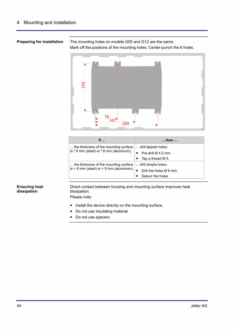
The mounting holes on models G05 and G12 are the same. Mark off the positions of the mounting holes. Center-punch the 6 holes.
170
14179
220
If ... ... then ...
... the thickness of the mounting surface is ³ 6 mm (steel) or ³ 8 mm (aluminum),
... drill tapped holes:
Pre-drill Ø 4.2 mm. Tap a thread M 5.
... the thickness of the mounting surface is < 6 mm (steel) or < 8 mm (aluminum),
... drill simple holes:
Drill the holes Ø 6 mm. Deburr the holes.
Direct contact between housing and mounting surface improves heat dissipation. Please note:
Install the device directly on the mounting surface. Do not use insulating material. Do not use spacers.
Preparing for installation
Ensuring heat dissipation
Jetter AG 45
JCM-350-E01/E02 Mounting and installation
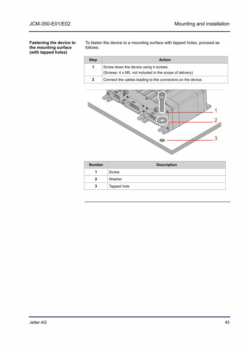
To fasten the device to a mounting surface with tapped holes, proceed as follows:
Step Action
1 Screw down the device using 4 screws. (Screws: 4 x M5, not included in the scope of delivery)
2 Connect the cables leading to the connectors on the device.
2
1
3
Number Description
1 Screw
2 Washer
3 Tapped hole
Fastening the device to the mounting surface (with tapped holes)

46 Jetter AG
4 Mounting and installation
Screw down the device as shown in the illustration:
21
3
45
Number Description
1 Screw
2 Washer
3 Through hole
4 Washer
5 Screw nut
Physical dimensions (see page 23)
Fastening the device to the mounting surface (with drilled holes)
Related topics

Jetter AG 47
JCM-350-E01/E02 Mounting and installation
4.2 Wiring
This chapter describes how to wire the JCM-350-E01/E02 and covers the following topics:
Wiring principle Example of wiring Power supply Pin assignment Technical specifications
Topic Page Wiring principle ............................................................................................. 48 JCM-350-E01/E02 - Power supply ............................................................... 50 Connecting peripheral devices to the JCM-350-E01/E02 ............................ 58 JCM-350-E01/E02 - I²t monitoring ................................................................ 81
Purpose of this chapter
Table of Contents
48 Jetter AG
4 Mounting and installation
Wiring principle
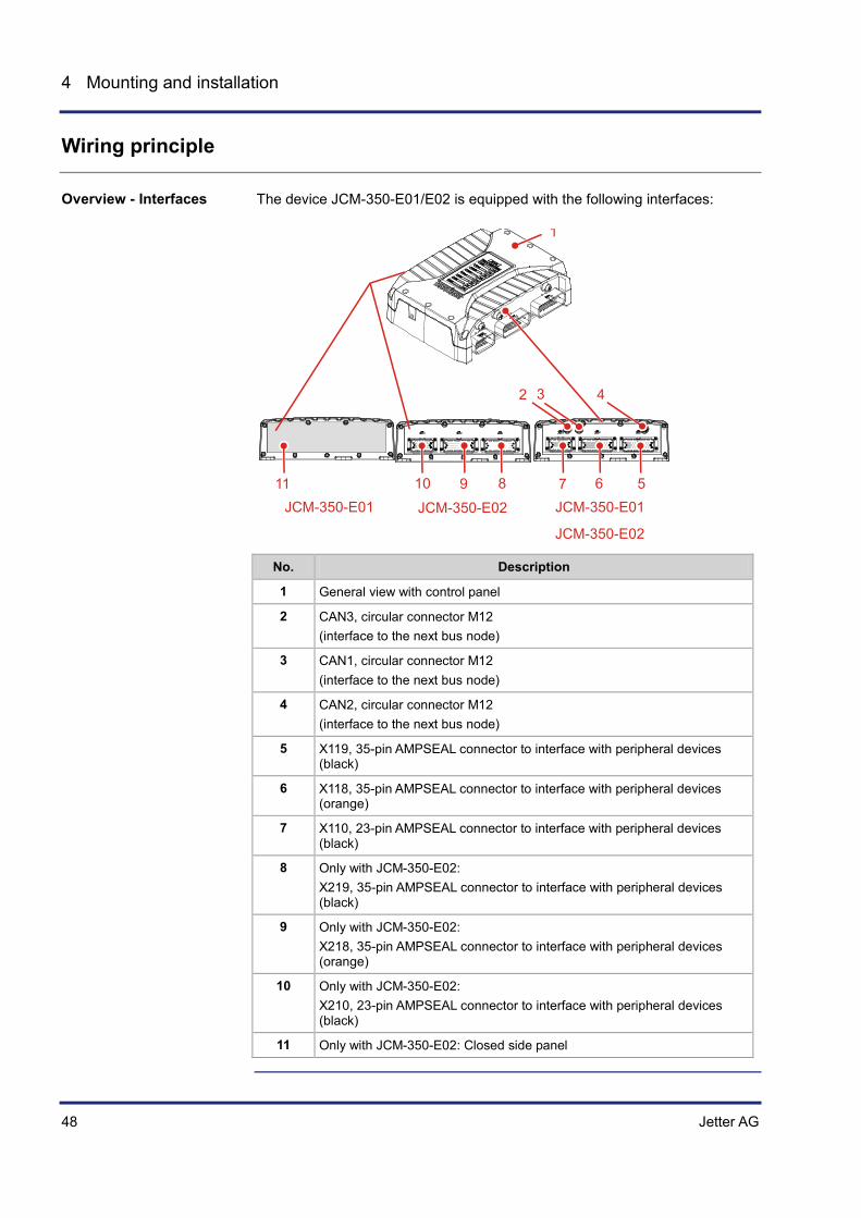
The device JCM-350-E01/E02 is equipped with the following interfaces:
79
2 3 4
5678910
JCM-350-E02JCM-350-E01
1
11JCM-350-E01
JCM-350-E02
No. Description
1 General view with control panel
2 CAN3, circular connector M12 (interface to the next bus node)
3 CAN1, circular connector M12 (interface to the next bus node)
4 CAN2, circular connector M12 (interface to the next bus node)
5 X119, 35-pin AMPSEAL connector to interface with peripheral devices (black)
6 X118, 35-pin AMPSEAL connector to interface with peripheral devices (orange)
7 X110, 23-pin AMPSEAL connector to interface with peripheral devices (black)
8 Only with JCM-350-E02: X219, 35-pin AMPSEAL connector to interface with peripheral devices (black)
9 Only with JCM-350-E02: X218, 35-pin AMPSEAL connector to interface with peripheral devices (orange)
10 Only with JCM-350-E02: X210, 23-pin AMPSEAL connector to interface with peripheral devices (black)
11 Only with JCM-350-E02: Closed side panel
Overview - Interfaces
Jetter AG 49
JCM-350-E01/E02 Mounting and installation
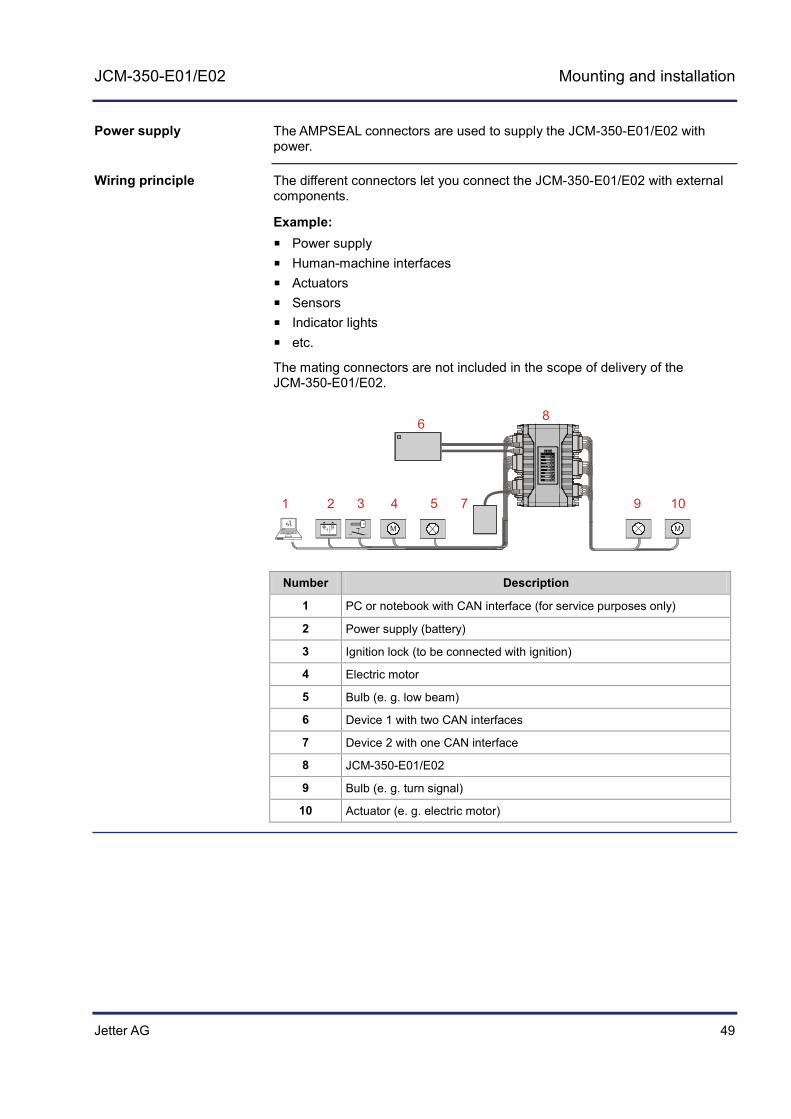
The AMPSEAL connectors are used to supply the JCM-350-E01/E02 with power.
The different connectors let you connect the JCM-350-E01/E02 with external components.
Example: Power supply Human-machine interfaces Actuators Sensors Indicator lights etc.
The mating connectors are not included in the scope of delivery of the JCM-350-E01/E02.
M M
2 53
86
1 74 9 10
Number Description
1 PC or notebook with CAN interface (for service purposes only)
2 Power supply (battery)
3 Ignition lock (to be connected with ignition)
4 Electric motor
5 Bulb (e. g. low beam)
6 Device 1 with two CAN interfaces
7 Device 2 with one CAN interface
8 JCM-350-E01/E02
9 Bulb (e. g. turn signal)
10 Actuator (e. g. electric motor)
Power supply
Wiring principle

50 Jetter AG
4 Mounting and installation
4.2.1 JCM-350-E01/E02 - Power supply
This chapter describes how to supply the JCM-350-E01/E02 with power.
The electronic system of the JCM-350-E01/E02 can be supplied with voltage (UC_UBAT) in different ways. When you engineer the voltage supply, take the following aspects into account:
Power supply directly from the battery (terminal 30) Power supply via ignition lock (terminal 15) Maximum current per supply line
Connecting the power supply to a JCM-350-E01/E02:
Connect the power supply of a JCM-350-E01 to connectors X118 and X119.
Connect the power supply of a JCM-350-E02 to connectors X118, X119, X218 and X219.
Differences in ground reference:
The ground reference of G05 models is connected with the enclosure. The ground reference of G12 models is isolated from the enclosure.
When you power up the JCM-350-E01/E02, the inrush current may several times exceed the normal operating current. Take this fact into account when defining the fuse rating.
If the power supply of the controller JCM-350 via X119.12 or X219.12 (only on JCM-350-E02) is interrupted, for example due to a broken wire, the controller is supplied through the following external power supplies:
• Power supply of H-bridges • Power supply of digital ouputs • Power supply of PWM outputs
You are free to choose to supply the controller via ignition (terminal 15) or directly from the battery (terminal 30).
Topic Page Connecting the supply voltage to X118/X218 ............................................... 51 Connecting the supply voltage to X119/X219 ............................................... 53 Sensor supply voltage ................................................................................... 56
Introduction
Power supply of electronic system
Properties of JCM-350-E01/E02
Table of Contents

Jetter AG 51
JCM-350-E01/E02 Mounting and installation
Connecting the supply voltage to X118/X218
This chapter describes the pin assignment of AMPSEAL connector X118/X218 for supplying the JCM-350-E01/E02 with power. The mating connector is a 35-pin AMPSEAL jack.
The illustration below shows the pin assignment of the connector X118/X218 with power supply and reference potentials: Connect the power supply from the battery as shown below:
1 12
13 23
24 35
X118
X218
Pin Description
2 Power supply of digital outputs 5 ... 8
3 Power supply of digital outputs 5 ... 8
6 Power supply of H-bridge 1
7 Power supply of H-bridge 1
10 Power supply of H-bridge 2
11 Power supply of H-bridge 2
17 Reference potential
18 Reference potential
28 Reference potential
29 Reference potential
The connecting cable must meet the following requirements:
Parameter Description
Core cross-section From 0.75 mm2 to 1.5 mm2 (AWG 20 ... 16)
Minimum insulation diameter 1.7 mm
Maximum insulation diameter 2.7 mm
Parameter Description
Permissible voltage range DC 7.5 V ... DC 32 V
Current consumption Sum of output currents of digital outputs 5 ... 8
Connecting pins X118.2, X118.3/ X218.2, X218.3
Introduction
Power supply via X118/X218
Note on cables
Power supply of digital outputs 5 ... 8 - Technical specifications

52 Jetter AG
4 Mounting and installation
Parameter Description
Permissible voltage range DC 7.5 V ... DC 32 V
Input current Total output current - H-bridge 1
Maximum output current 16 A
Connecting pins X118.6, X118.7/ X218.6, X218.7
Parameter Description
Permissible voltage range DC 7.5 V ... DC 32 V
Input current Total output current - H-bridge 2
Maximum output current 16 A
Connecting pins X118.10, X118.11/ X218.10, X218.11
Pin assignment X118 (see page 248) Pin assignment X218 (see page 255)
Power supply of H-bridge 1 - Technical specifications
Power supply of H-bridge 2 - Technical specifications
Related topics

Jetter AG 53
JCM-350-E01/E02 Mounting and installation
Connecting the supply voltage to X119/X219
This chapter describes the pin assignment of AMPSEAL connector X119/X219 for supplying the JCM-350-E01/E02 with power. The mating connector is a 35-pin AMPSEAL jack.
The illustration below shows the pin assignment of the connector X119/X219 with power supply and reference potentials: Connect the power supply from the battery as shown below:
1 12
13 23
24 35
X119
X219
Pin Description
10 Power supply of digital outputs 1 ... 4
11 Power supply of digital outputs 1 ... 4
12 Power supply of electronic system and pins X119.31, X219.31, X110.18 and X210.18.
17 Reference potential
18 Reference potential
19 Power supply of analog outputs
20 Reference potential
21 Power supply of PWM outputs
22 Output: Power supply of external analog peripheral devices
23 Power supply of digital inputs
28 Reference potential
29 Reference potential
The size of the power supply unit line must be rated at a minimum current of 2.2 A.
Pins X119.12 and X219.12 supply the following components:
Electronic system of JCM-350-E01/E02 Pins X119.31, X219.31 supply the sensors of external analog peripherals
with power, maximum current 1 A Pins X110.18, X210.18 supply the sensors of external digital peripherals
with power, maximum current 1 A
Introduction
Power supply via X119/X219
Note on power supply

54 Jetter AG
4 Mounting and installation
The connecting cable must meet the following requirements:
Parameter Description
Core cross-section From 0.75 mm2 to 1.5 mm2 (AWG 20 ... 16)
Minimum insulation diameter 1.7 mm
Maximum insulation diameter 2.7 mm
Parameter Description
Permissible voltage range DC 7.5 V ... DC 32 V
Current consumption Sum of output currents of digital outputs 1 ... 4
Connecting pins X119.10, X119.11/ X219.10, X219.11
Parameter Description
Operating voltage - device DC 7 V ... 32 V
Operating voltage - controller ≥ DC 5.5 V
Typical input current (at 24 V power supply) 200 mA + encoder supply (only for G12 models)
Connecting pins X119.12/X219.12
Parameter Description
Permissible voltage range DC 7.5 V ... DC 32 V
Input current Corresponds to the total output power of all analog outputs
Maximum input current 400 mA
Connecting pins X119.19/X219.19
Parameter Description
Permissible voltage range DC 7.5 V ... DC 32 V
Input current (at PWM power supply = 24 V)
Corresponds to the total output power of all PWM outputs
Maximum total output current of all PWM outputs
8 A
Connecting pins X119.21/X219.21
Note on cables
Power supply of digital outputs 1 ... 4 - Technical specifications
Power supply UC_UBAT - Technical specifications
Power supply of analog output - Technical specifications
Power supply of PWM outputs - Technical specifications

Jetter AG 55
JCM-350-E01/E02 Mounting and installation
Parameter Description
Permissible voltage range DC 7.5 V ... DC 32 V
Input current (at 24 V power supply) 150 mA
Connecting pins X119.23/X219.23
The following information applies only to JCM-350-G05:
Parameter Description
Permissible voltage range DC 7.5 V ... DC 32 V
Peak current 1 A
Connecting pins X119.22/X219.22
Pin assignment X119 (see page 258) Pin assignment X219 (see page 258)
Power supply of digital inputs - Technical specifications
Power supply of analog inputs - Technical data
Related topics

56 Jetter AG
4 Mounting and installation
Sensor supply voltage
There are two sensor supply systems for supplying external analog and digital electronic circuits. Both sensor supply systems can be activated from the JCM-350-E01/E02.
Parameter Description
Protection Electronic activation (only on G12 models)
Maximum current for digital electronics
1 A continuous current 2.5 A maximum current
Maximum current for analog electronics
1 A continuous current 2.5 A maximum current
Overload behavior If the maximum current per output is exceeded, the sensor supplies start to pulsate (only on G12 models)
Ensure that on a G05 model the maximum current does not exceed the following limits:
1 A for digital peripherals 1 A for analog peripherals
The illustration below shows the pins used for sensor supply:
1 12
13 23
24 35
X119
X219
1 8
9 15
16 23
X110
X210
Pin Socket Description
31 X119 Sensor supply for analog peripherals
31 X219 Sensor supply for analog peripherals
18 X110 Sensor supply for digital peripherals
18 X210 Sensor supply for digital peripherals
Introduction
Sensor supply properties
Sensor supply - Pins

Jetter AG 57
JCM-350-E01/E02 Mounting and installation
Pin assignment X110 (see page 253) Pin assignment X210 (see page 253) Pin assignment X119 (see page 258) Pin assignment X219 (see page 258)
Related topics

58 Jetter AG
4 Mounting and installation
4.2.2 Connecting peripheral devices to the JCM-350-E01/E02
This chapter describes how to use the inputs/outputs of the JCM-350-E01/E02.
Topic Page Connecting analog inputs ............................................................................. 59 Connecting analog outputs ........................................................................... 61 CAN interfaces - Connection ........................................................................ 63 Connecting digital frequency/pulse inputs .................................................... 65 Connecting digital inputs ............................................................................... 67 Connecting digital outputs ............................................................................. 70 Connecting H-bridges ................................................................................... 73 Connecting PWM outputs ............................................................................. 75 Connecting relays ......................................................................................... 78
Introduction
Table of Contents
Jetter AG 59
JCM-350-E01/E02 Mounting and installation
Connecting analog inputs
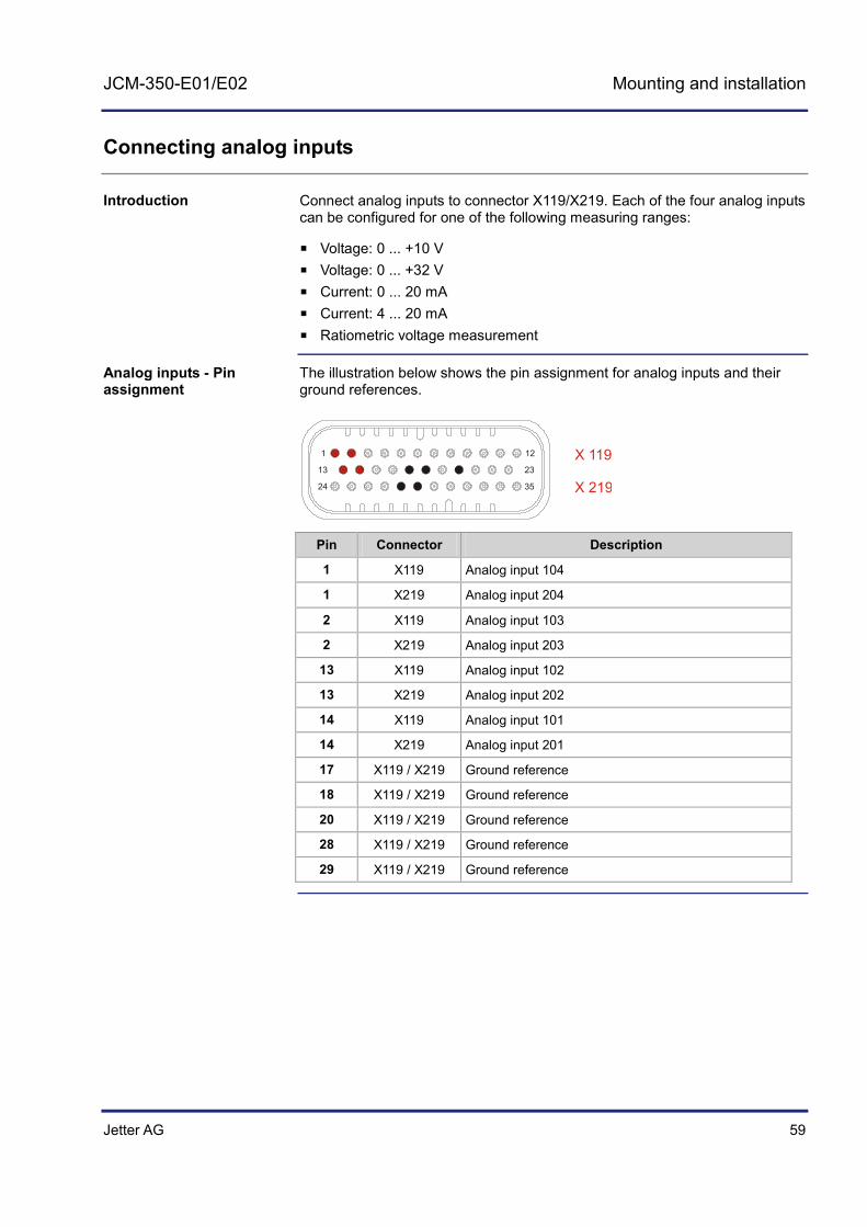
Connect analog inputs to connector X119/X219. Each of the four analog inputs can be configured for one of the following measuring ranges:
Voltage: 0 ... +10 V Voltage: 0 ... +32 V Current: 0 ... 20 mA Current: 4 ... 20 mA Ratiometric voltage measurement
The illustration below shows the pin assignment for analog inputs and their ground references.
1 12
13 23
24 35
X 119
X 219
Pin Connector Description
1 X119 Analog input 104
1 X219 Analog input 204
2 X119 Analog input 103
2 X219 Analog input 203
13 X119 Analog input 102
13 X219 Analog input 202
14 X119 Analog input 101
14 X219 Analog input 201
17 X119 / X219 Ground reference
18 X119 / X219 Ground reference
20 X119 / X219 Ground reference
28 X119 / X219 Ground reference
29 X119 / X219 Ground reference
Introduction
Analog inputs - Pin assignment
60 Jetter AG
4 Mounting and installation
Parameter Description
Maximum input voltage for voltage measurements
+32 V
Maximum input current for current measurements
22.5 mA (+9 V)
Resolution 12 bits
Accuracy 99.5 %
Input frequency 50 Hz
Limit frequency of 10 V range 250 Hz, 3 dB attenuation of input signal, Input impedance: 43 kΩ
Limit frequency of 32 V range 660 Hz, 3 dB attenuation of input signal, Input impedance: 35 kΩ
Input impedance (voltage) 35 kΩ / 43 kΩ
Input impedance (current) 400 Ω
The following information applies only to JCM-350-G05:
Parameter Description
Permissible voltage range DC 7.5 V ... DC 32 V
Peak current 1 A
Connecting pins X119.22/X219.22
Connecting the supply voltage to X119/X219 (see page 53) Programming: Retrieving analog values (see page 226)
Analog inputs - Technical specifications
Power supply of analog inputs - Technical data
Related topics
Jetter AG 61
JCM-350-E01/E02 Mounting and installation
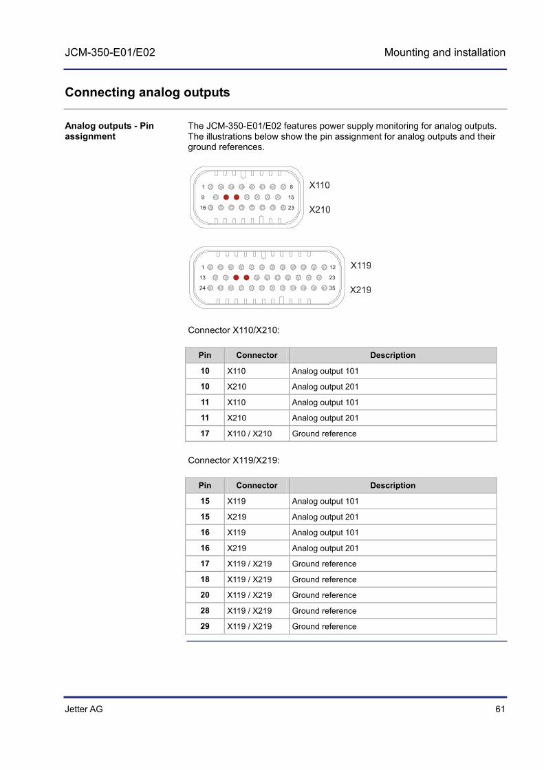
Connecting analog outputs
The JCM-350-E01/E02 features power supply monitoring for analog outputs. The illustrations below show the pin assignment for analog outputs and their ground references.
1 12
13 23
24 35 X219
X119
1 8
9 15
16 23 X210
X110
Connector X110/X210:
Pin Connector Description
10 X110 Analog output 101
10 X210 Analog output 201
11 X110 Analog output 101
11 X210 Analog output 201
17 X110 / X210 Ground reference Connector X119/X219:
Pin Connector Description
15 X119 Analog output 101
15 X219 Analog output 201
16 X119 Analog output 101
16 X219 Analog output 201
17 X119 / X219 Ground reference
18 X119 / X219 Ground reference
20 X119 / X219 Ground reference
28 X119 / X219 Ground reference
29 X119 / X219 Ground reference
Analog outputs - Pin assignment
62 Jetter AG
4 Mounting and installation
Parameter Description
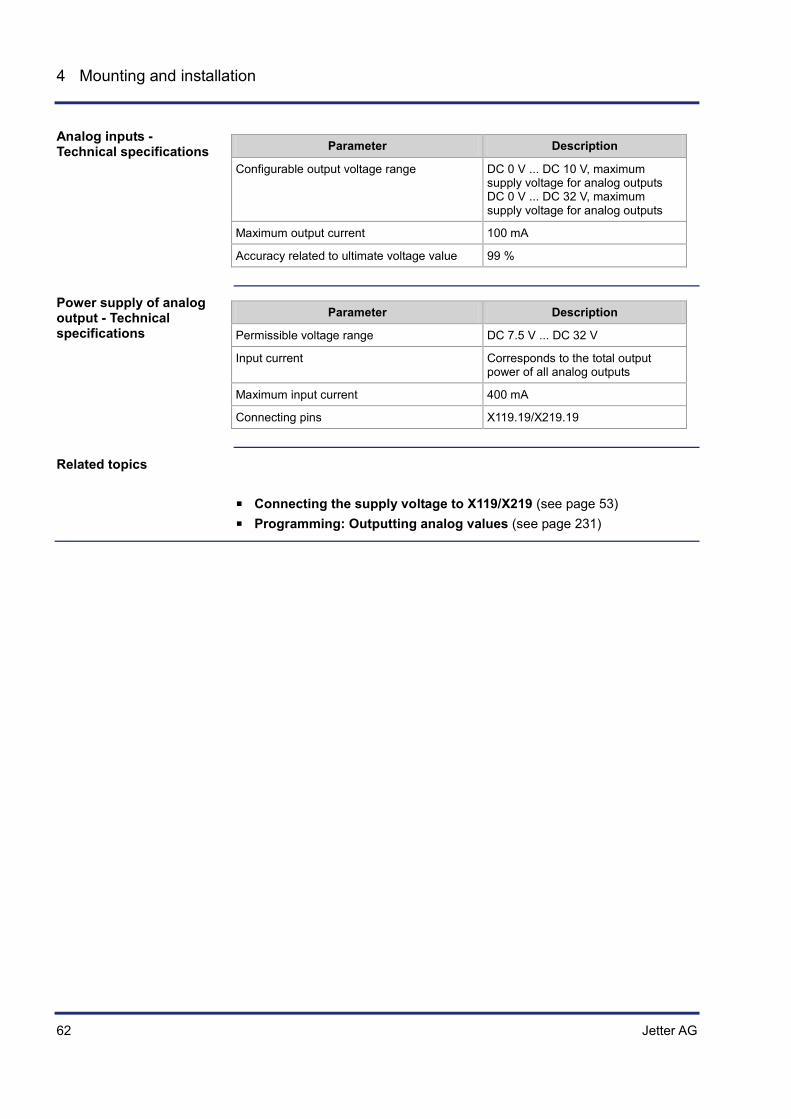
Configurable output voltage range DC 0 V ... DC 10 V, maximum supply voltage for analog outputs DC 0 V ... DC 32 V, maximum supply voltage for analog outputs
Maximum output current 100 mA
Accuracy related to ultimate voltage value 99 %
Parameter Description
Permissible voltage range DC 7.5 V ... DC 32 V
Input current Corresponds to the total output power of all analog outputs
Maximum input current 400 mA
Connecting pins X119.19/X219.19
Connecting the supply voltage to X119/X219 (see page 53) Programming: Outputting analog values (see page 231)
Analog inputs - Technical specifications
Power supply of analog output - Technical specifications
Related topics

Jetter AG 63
JCM-350-E01/E02 Mounting and installation
CAN interfaces - Connection
This chapter describes the pin assignment of the different CAN ports (interfaces). The JCM-350-E01/E02 has five separate CAN interfaces.
The illustration below shows the CAN connectors of the JCM-350-E01/E02:
1 2
345
CAN 1
CAN 2
CAN 3
1 2
345
1 2
345
These connectors are 5-pin male connectors (thread M12) by Binder.
The illustration below shows the pin assignment of the CAN interface. The pin assignment is identical for connectors 1 ... 3. Letter x is used in the table as placeholder for the corresponding CAN interface: x = 1 ... 3.
1 2
345
Pin Description
1 -
2 -
3 On G05 models: Ground reference and enclosure On G12 models: Not used
4 CAN-High of interface x
5 CAN-Low of interface x
Introduction
Overview - CAN Interfaces
M12 CAN interface

64 Jetter AG
4 Mounting and installation
The cable of the mating connector must meet the following requirements:
Parameter Description
Cable type CAN 5-pin (CAN-H and CAN-L twisted, shielded)
Minimum core cross-section 0.34 mm²
Maximum cable length at 250 kbits/s < 50 m
The following mating connectors are compatible with the 5-pin connector M12:
5-pin connector (female) M12 by Binder 5-pin connector (female) M12 by Escha
These mating connectors are not included in the scope of delivery.
CAN interfaces 4 and 5 are implemented in connector X119.
1 12
13 23
24 35
X119
Pin Signal Description
34 CAN-H CAN High, interface 4
32 CAN-L CAN Low, interface 4
35 CAN-H CAN High, interface 5
30 CAN-L CAN Low, interface 5
Parameter Description
Baud rates 250 kBaud
Bus termination None
External termination recommended 120 Ω
Note on cables
Mating parts
CAN interfaces 4 and 5
CAN interface - Technical specifications

Jetter AG 65
JCM-350-E01/E02 Mounting and installation
Connecting digital frequency/pulse inputs
Frequency/pulse inputs let you capture the frequency of digital signals. The illustrations below show the pin assignment for frequency/pulse inputs and their ground references.
1 12
13 23
24 35
1 8
9 15
16 23
X118
X218
X110
X210
Connector X118/X218:
Pin Connector Description
12 X118 Frequency input 101
12 X218 Frequency input 201
17 X118 / X218 Ground reference
18 X118 / X218 Ground reference
20 X118 Frequency input 102
20 X218 Frequency input 202
28 X118 / X218 Ground reference
29 X118 / X218 Ground reference
Connector X110/X210:
Pin Connector Description
17 X110 / X210 Ground reference
19 X110 Frequency input 103
19 X210 Frequency input 203
20 X110 Frequency input 104
20 X210 Frequency input 204
Connecting digital frequency/pulse inputs

66 Jetter AG
4 Mounting and installation
Parameter Description
Type of inputs Active-low inputs with pull-down resistor
Permissible voltage range DC 0 V ... DC 32 V
Threshold level OFF < 0.3 x supply voltage of digital inputs for JCM-350-Exx-G05
< 0.2 x supply voltage of digital inputs for JCM-350-Exx-G12
Threshold level ON > 0.7 x supply voltage of digital inputs for JCM-350-Exx-G05
> 0.3 x supply voltage of digital inputs for JCM-350-Exx-G12
Typical input resistance 3.2 kΩ
Typical input current 7.5 mA
Maximum input frequency 50 kHz
Connecting the supply voltage to X119/X219 (see page 53) Programming: Retrieving frequency inputs (see page 202)
Frequency/pulse inputs - Technical specifications
Related topics
Jetter AG 67
JCM-350-E01/E02 Mounting and installation
Connecting digital inputs
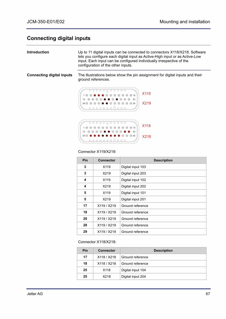
Up to 11 digital inputs can be connected to connectors X118/X218. Software lets you configure each digital input as Active-High input or as Active-Low input. Each input can be configured individually irrespective of the configuration of the other inputs.
The illustrations below show the pin assignment for digital inputs and their ground references.
1 12
13 23
24 35
1 12
13 23
24 35
X119
X219
X118
X218
Connector X119/X219:
Pin Connector Description
3 X119 Digital input 103
3 X219 Digital input 203
4 X119 Digital input 102
4 X219 Digital input 202
5 X119 Digital input 101
5 X219 Digital input 201
17 X119 / X219 Ground reference
18 X119 / X219 Ground reference
20 X119 / X219 Ground reference
28 X119 / X219 Ground reference
29 X119 / X219 Ground reference
Connector X118/X218:
Pin Connector Description
17 X118 / X218 Ground reference
18 X118 / X218 Ground reference
25 X118 Digital input 104
25 X218 Digital input 204
Introduction
Connecting digital inputs

68 Jetter AG
4 Mounting and installation
Pin Connector Description
26 X118 Digital input 105
26 X218 Digital input 205
27 X118 Digital input 106
27 X218 Digital input 206
28 X118 / X218 Ground reference
29 X118 / X218 Ground reference
30 X118 Digital input 107
30 X218 Digital input 207
31 X118 Digital input 108
31 X218 Digital input 208
32 X118 Digital input 109
32 X218 Digital input 209
23 X118 Digital input 110
23 X218 Digital input 210
22 X118 Digital input 111
22 X218 Digital input 211
Active-high and active-low inputs are evaluated in different ways:
Active-high inputs are measured against reference ground. Active-low inputs are measured against the digital supply voltage.
Depending on the configuration (active-high or active-low) the following switching statuses are possible:
Configuration State Result in register R 600y001xx
0 = Active-low input n.c. 0
24 V 0
0 V 1
1 = Active-high input n.c. 0
24 V 1
0 V 0
Note: The abbreviation "n.c." stands for "not connected". The placeholder "xx" stands for digital input 01 ... 11.
Note on power supply
Switching status

Jetter AG 69
JCM-350-E01/E02 Mounting and installation
Parameter Description
Type of inputs Active-high or active-low input (programmable)
Permissible voltage range DC 7.5 V ... DC 32 V
Typical threshold level OFF Active-high: < 0.3 x supply voltage of digital inputs Active-low: > 0.7 x supply voltage of digital inputs
Typical threshold level ON Active-high: > 0.7 x supply voltage of digital inputs Active-low: < 0.3 x supply voltage of digital inputs
Typical input resistance 3.2 kΩ
Typical input current (U = 24 V) 7.5 mA
Maximum input frequency 50 Hz
Parameter Description
Permissible voltage range DC 7.5 V ... DC 32 V
Input current (at 24 V power supply) 150 mA
Connecting pins X119.23/X219.23
Pin assignment X119 (see page 250) Pin assignment X219 (see page 258) Connecting the supply voltage to X119/X219 (see page 53) Programming: Retrieving digital values (see page 197)
Digital Inputs - Technical Data
Power supply of digital inputs - Technical specifications
Related topics
70 Jetter AG
4 Mounting and installation
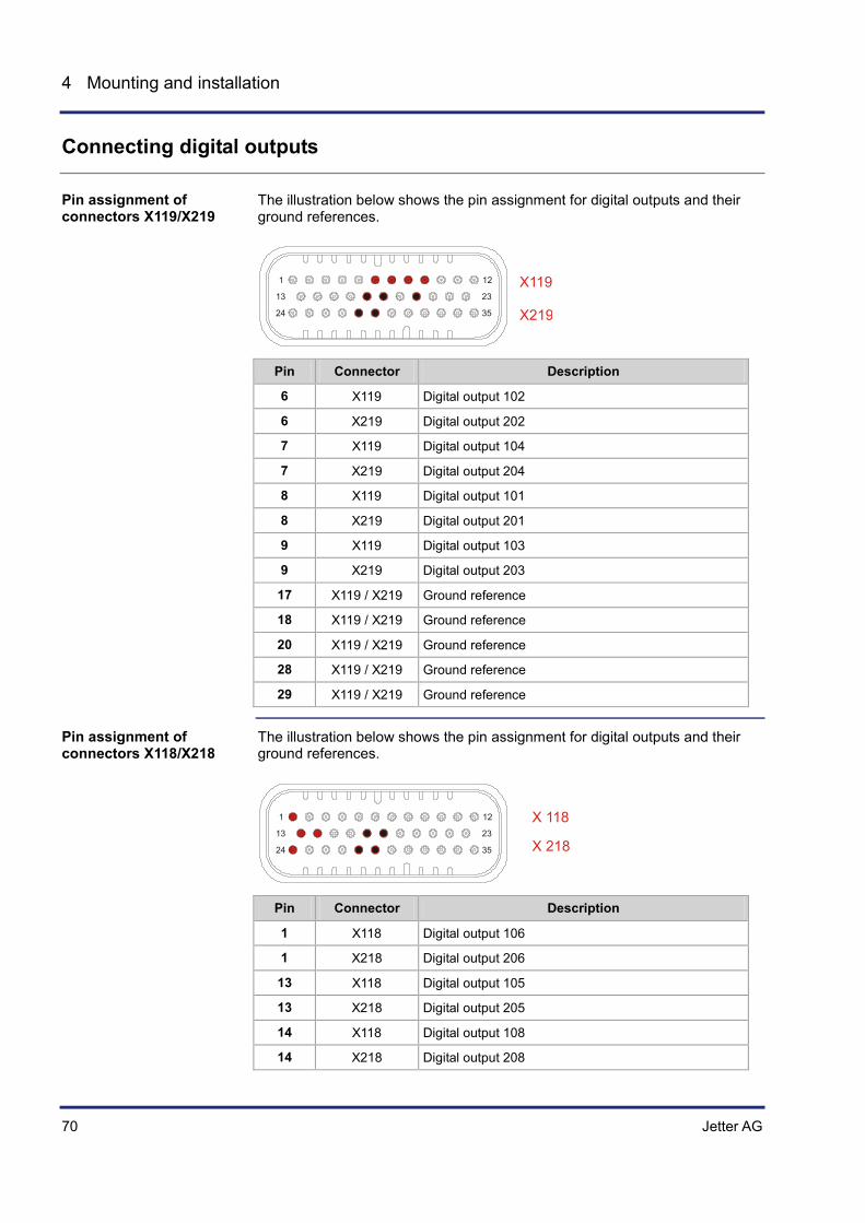
Connecting digital outputs
The illustration below shows the pin assignment for digital outputs and their ground references.
1 12
13 23
24 35
X119
X219
Pin Connector Description
6 X119 Digital output 102
6 X219 Digital output 202
7 X119 Digital output 104
7 X219 Digital output 204
8 X119 Digital output 101
8 X219 Digital output 201
9 X119 Digital output 103
9 X219 Digital output 203
17 X119 / X219 Ground reference
18 X119 / X219 Ground reference
20 X119 / X219 Ground reference
28 X119 / X219 Ground reference
29 X119 / X219 Ground reference
The illustration below shows the pin assignment for digital outputs and their ground references.
1 12
13 23
24 35
X 118
X 218
Pin Connector Description
1 X118 Digital output 106
1 X218 Digital output 206
13 X118 Digital output 105
13 X218 Digital output 205
14 X118 Digital output 108
14 X218 Digital output 208
Pin assignment of connectors X119/X219
Pin assignment of connectors X118/X218
Jetter AG 71
JCM-350-E01/E02 Mounting and installation
Pin Connector Description
17 X118 / X218 Ground reference
18 X118 / X218 Ground reference
24 X118 Digital output 107
24 X218 Digital output 207
28 X118 / X218 Ground reference
29 X118 / X218 Ground reference
Parameter Description
Maximum rated current per output 8 A
Total current for outputs 101 ... 104 16 A
Total current for outputs 105 ... 108 16 A
Total current for outputs 201 ... 204 16 A
Total current for outputs 205 ... 208 16 A
Switching frequency 100 Hz
Allowed overload current per output during power-up
40 A for 500 ms
Allowed overload current per output during power-up
16 A for 4 s
Minimum voltage per output; dependent on the supply voltage for digital outputs
7.0 V
Maximum voltage per output; dependent on the supply voltage for digital outputs
32 V
Parameter Description
Permissible voltage range DC 7.5 V ... DC 32 V
Current consumption Sum of output currents of digital outputs 1 ... 4
Connecting pins X119.10, X119.11/ X219.10, X219.11
Parameter Description
Permissible voltage range DC 7.5 V ... DC 32 V
Current consumption Sum of output currents of digital outputs 5 ... 8
Connecting pins X118.2, X118.3/ X218.2, X218.3
Digital outputs - Technical specifications
Power supply of digital outputs 1 ... 4 - Technical specifications
Power supply of digital outputs 5 ... 8 - Technical specifications

72 Jetter AG
4 Mounting and installation
Connecting the supply voltage to X118/X218 (see page 51) Connecting the supply voltage to X119/X219 (see page 53) Programming: Outputting digital values (see page 192)
Related topics

Jetter AG 73
JCM-350-E01/E02 Mounting and installation
Connecting H-bridges
The block diagram below is a simplified illustration of the H-bridges. These H-bridges are controlled by electronic switches.
UBAT_BRUE[1..2]
0R003
BRUE[1..2]_OUTLI
BRUE[1..2]_OUTRE
DIAG
1
2
3
Number Description
1 A shunt resistor in the H-bridge supply line measures the total current
2 Symbolically depicted: H-bridge switch
3 H-bridge outputs
The controller JCM-350-E01/E02 monitors the power supply of H-bridges. The illustration below shows the pin assignment for H-bridges and their ground references.
1 12
13 23
24 35
X118
X218
Pin Connector Description
4, 15 X118 H-bridge output 101, right
4, 15 X218 H-bridge output 201, right
5, 16 X118 H-bridge output 101, left
5, 16 X218 H-bridge output 201, left
6 X118 / X218 H-bridge ground reference
7 X118 / X218 H-bridge ground reference
8, 19 X118 H-bridge output 102, right
8, 19 X218 H-bridge output 202, right
Block diagram
Connecting H-bridges

74 Jetter AG
4 Mounting and installation
Pin Connector Description
9, 21 X118 H-bridge output 102, left
9, 21 X218 H-bridge output 202, left
10 X118 / X218 H-bridge ground reference
11 X118 / X218 H-bridge ground reference
Parameter Description
Voltage supply of outputs 0.3 V
Overload behavior 80 A for 500 ms 32 A for 4 s
Current measurement, resolution 12 bits
Accuracy related to twice the rated current 95 %
Switching frequency (1/period length) 100 Hz ... 4 kHz
Frequency accuracy 100 ppm
Resolution of pulse control factor 20 ns
Parameter Description
Permissible voltage range DC 7.5 V ... DC 32 V
Input current Total output current - H-bridge 1
Maximum output current 16 A
Connecting pins X118.6, X118.7/ X218.6, X218.7
Parameter Description
Permissible voltage range DC 7.5 V ... DC 32 V
Input current Total output current - H-bridge 2
Maximum output current 16 A
Connecting pins X118.10, X118.11/ X218.10, X218.11
Connecting the supply voltage to X118/X218 (see page 51) Connecting the supply voltage to X119/X219 (see page 53) Programming: H-bridge (see page 217)
H-bridges 1/2 - Technical specifications
Power supply of H-bridge 1 - Technical specifications
Power supply of H-bridge 2 - Technical specifications
Related topics
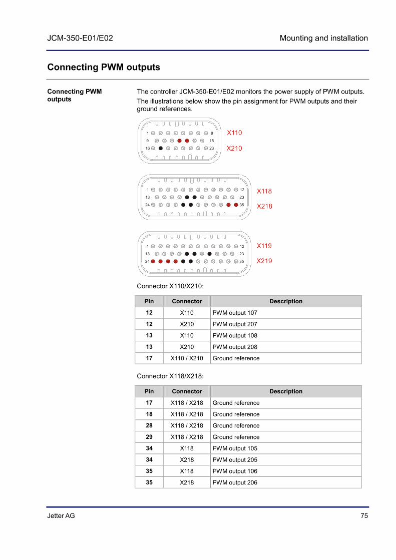
Jetter AG 75
JCM-350-E01/E02 Mounting and installation
Connecting PWM outputs
The controller JCM-350-E01/E02 monitors the power supply of PWM outputs. The illustrations below show the pin assignment for PWM outputs and their ground references.
1 8
9 15
16 23
X110
X210
1 12
13 23
24 35
X118
X218
1 12
13 23
24 35
X119
X219
Connector X110/X210:
Pin Connector Description
12 X110 PWM output 107
12 X210 PWM output 207
13 X110 PWM output 108
13 X210 PWM output 208
17 X110 / X210 Ground reference
Connector X118/X218:
Pin Connector Description
17 X118 / X218 Ground reference
18 X118 / X218 Ground reference
28 X118 / X218 Ground reference
29 X118 / X218 Ground reference
34 X118 PWM output 105
34 X218 PWM output 205
35 X118 PWM output 106
35 X218 PWM output 206
Connecting PWM outputs

76 Jetter AG
4 Mounting and installation
Connector X119/X219:
Pin Connector Description
17 X119 / X219 Ground reference
18 X119 / X219 Ground reference
20 X119 / X219 Ground reference
24 X119 PWM output 101
24 X219 PWM output 201
25 X119 PWM output 102
25 X219 PWM output 202
26 X119 PWM output 103
26 X219 PWM output 203
27 X119 PWM output 104
27 X219 PWM output 204
28 X119 / X219 Ground reference
29 X119 / X219 Ground reference
Parameter Description
Type of outputs High-side
Nominal current of individual outputs 2 A
Typical output voltage at nominal current Power supply PWM -200
Overload protection at power-up 10 A for 500 ms 4 A for 4 s
Total current of all 8 PWM outputs 8 A
Clock frequency 25 Hz ... 1 KHz Can be configured in steps of 25 Hz
Frequency accuracy 95 %
Resolution of pulse control factor 20.083 ns
Accuracy of pulse control factor ±2 µs
Switch-on frequency under overload conditions
Depending on thermal overall condition
Switch-on frequency without overload No restriction
Load Resistive, inductive, lamps
Protective circuitry Capacitive, free-wheeling diode
Diagnostic functions Overload, short circuit
PWM outputs - Technical specifications
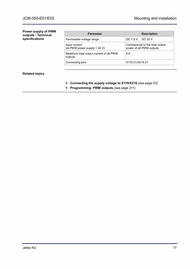
Jetter AG 77
JCM-350-E01/E02 Mounting and installation
Parameter Description
Permissible voltage range DC 7.5 V ... DC 32 V
Input current (at PWM power supply = 24 V)
Corresponds to the total output power of all PWM outputs
Maximum total output current of all PWM outputs
8 A
Connecting pins X119.21/X219.21
Connecting the supply voltage to X119/X219 (see page 53) Programming: PWM outputs (see page 211)
Power supply of PWM outputs - Technical specifications
Related topics

78 Jetter AG
4 Mounting and installation
Connecting relays
Connector X110/X210 lets you connect four relay contacts. The JCM-350-E01/E02 is equipped with two different relay types. These two relay types are rated at different breaking currents.
Relay 101, 102, 201, 202 High-current relay Relay 103, 104, 203, 204 Standard relay
Abbreviations used in the block diagram:
COMM for Common NO for Normally Open NC for Normally Closed
X y10.01
X y10.04
X y10.05
X y10.15
X y10.09
X y10.03
X y10.08
X y10.14
X y10.16
X y10.02
X y10.06
X y10.07
REL1_COMM
REL2_COMM
REL3_COMM
REL4_COMM
REL1_NO
REL2_NO
REL3_NO
REL4_NO
REL1_NC
REL2_NC
REL3_NC
REL4_NC
µC
µC
µC
µC
y = 1 : JCM-350-E01-xxxy = 2 : JCM-350-E02-xxx
Introduction
Block diagram

Jetter AG 79
JCM-350-E01/E02 Mounting and installation
The illustration below shows the pin assignment of the relays.
1 8
9 15
16 23
X 110X 210
Pin Socket Description
1 X110 Common - relay 101
1 X210 Common - relay 201
9 X110 NO - relay 101
9 X210 NO - relay 201
16 X110 NC - relay 102
16 X210 NC - relay 202
4 X110 Common - relay 102
4 X210 Common - relay 202
3 X110 NO - relay 102
3 X210 NO - relay 202
2 X110 NC - relay 102
2 X210 NC - relay 202
5 X110 Common - relay 103
5 X210 Common - relay 203
8 X110 NO - relay 103
8 X210 NO - relay 203
6 X110 NC - relay 103
6 X210 NC - relay 203
15 X110 Common - relay 104
15 X210 Common - relay 204
14 X110 NO - relay 104
14 X210 NO - relay 204
7 X110 NC - relay 104
7 X210 NC - relay 204
Connecting relays
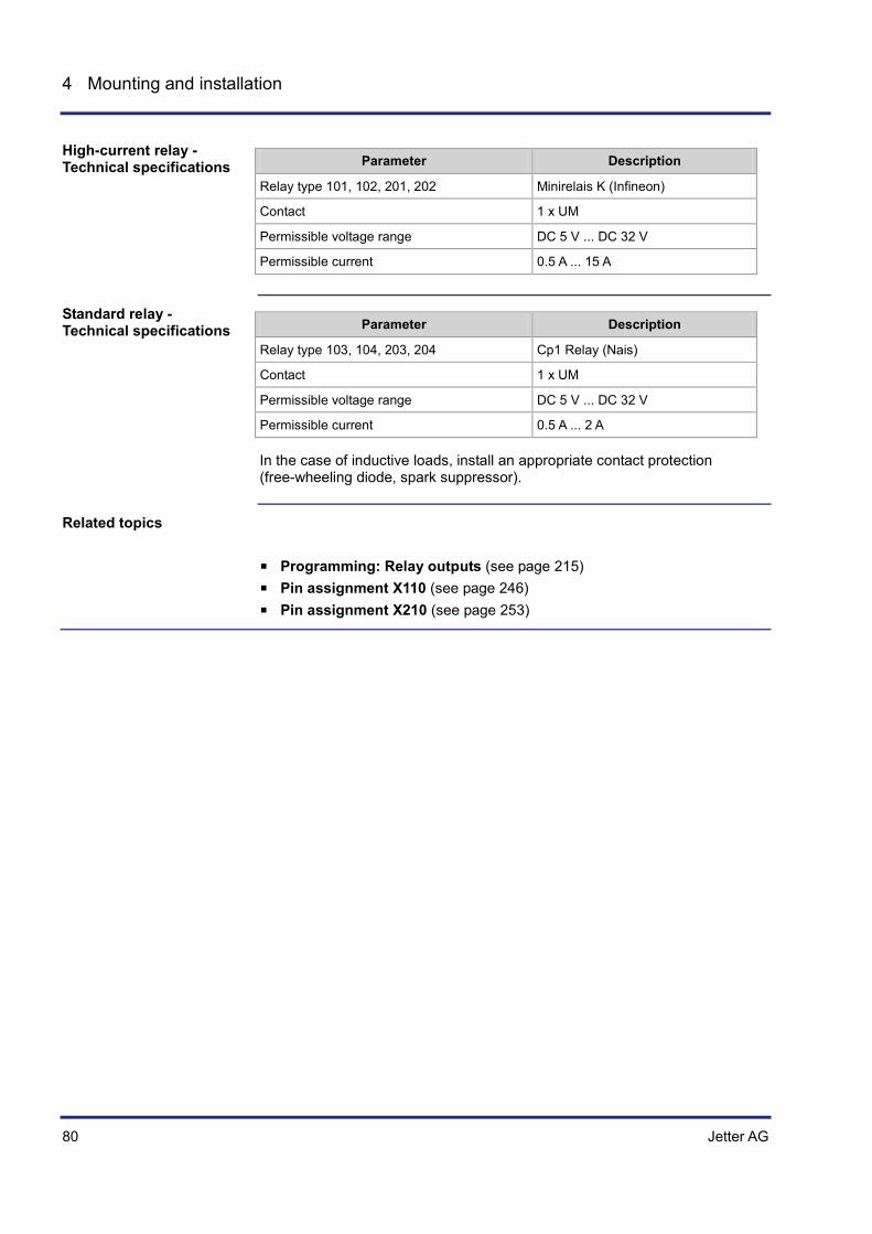
80 Jetter AG
4 Mounting and installation
Parameter Description
Relay type 101, 102, 201, 202 Minirelais K (Infineon)
Contact 1 x UM
Permissible voltage range DC 5 V ... DC 32 V
Permissible current 0.5 A ... 15 A
Parameter Description
Relay type 103, 104, 203, 204 Cp1 Relay (Nais)
Contact 1 x UM
Permissible voltage range DC 5 V ... DC 32 V
Permissible current 0.5 A ... 2 A
In the case of inductive loads, install an appropriate contact protection (free-wheeling diode, spark suppressor).
Programming: Relay outputs (see page 215) Pin assignment X110 (see page 246) Pin assignment X210 (see page 253)
High-current relay - Technical specifications
Standard relay - Technical specifications
Related topics

Jetter AG 81
JCM-350-E01/E02 Mounting and installation
4.2.3 JCM-350-E01/E02 - I²t monitoring
This chapter describes I2t monitoring implemented in JCM-350-E01/E02. This feature uses I2t graphs for monitoring purposes. If the current per unit of time exceeds the limit, the controller issues an error message.
Topic Page Retrieving I²t monitoring data ....................................................................... 82 Digital outputs - I²t monitoring of H-bridges and power supply ..................... 84 I²t monitoring of digital outputs ..................................................................... 87
Introduction
Table of Contents

82 Jetter AG
4 Mounting and installation
Retrieving I²t monitoring data
The I2t curve is a measure of load and internal heating-up of the device. I2t monitoring is available for the following outputs:
H-bridges Digital outputs 1 ... 8 Total current of power supply for digital outputs 1 ... 4 Total current of power supply for digital outputs 5 ... 8
The device calculates the current load per output and adds a factor I2 per time t. The value can be read out as percentage ranging from 0 ... 100 %.
The JCM-350-E01/E02 calculates the average power dissipation by the following formula:
Variable Description
x(t) Proportional value of average power dissipation in per cent (0 ... 100 %)
avg_I Average current
nom_I Rated current
t Elapsed time
T Time constant
Output Parameter Description
H-bridge Rated current nom_I Time constant
I = 16 A T = 13.9 s
Digital output Rated current nom_I Time constant
I = 8 A T = 13.9 s
Total current - digital outputs 1 ... 4
Rated current nom_I Time constant
I = 16 A T = 13.9 s
Total current - digital outputs 5 ... 8
Rated current nom_I Time constant
I = 16 A T = 13.9 s
I2t curve
I2t calculation
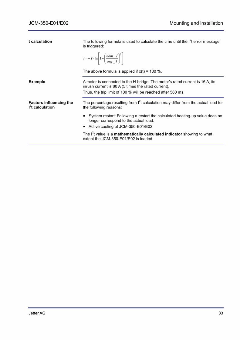
Jetter AG 83
JCM-350-E01/E02 Mounting and installation
The following formula is used to calculate the time until the I2t error message is triggered:
The above formula is applied if x(t) = 100 %.
A motor is connected to the H-bridge. The motor's rated current is 16 A, its inrush current is 80 A (5 times the rated current). Thus, the trip limit of 100 % will be reached after 560 ms.
The percentage resulting from I2t calculation may differ from the actual load for the following reasons:
System restart: Following a restart the calculated heating-up value does no longer correspond to the actual load.
Active cooling of JCM-350-E01/E02
The I2t value is a mathematically calculated indicator showing to what extent the JCM-350-E01/E02 is loaded.
t calculation
Example
Factors influencing the I2t calculation
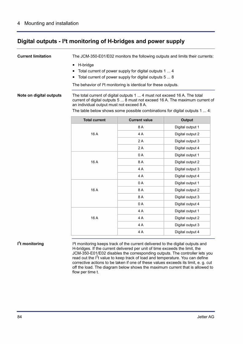
84 Jetter AG
4 Mounting and installation
Digital outputs - I²t monitoring of H-bridges and power supply
The JCM-350-E01/E02 monitors the following outputs and limits their currents:
H-bridge Total current of power supply for digital outputs 1 ... 4 Total current of power supply for digital outputs 5 ... 8
The behavior of I²t monitoring is identical for these outputs.
The total current of digital outputs 1 ... 4 must not exceed 16 A. The total current of digital outputs 5 ... 8 must not exceed 16 A. The maximum current of an individual output must not exceed 8 A. The table below shows some possible combinations for digital outputs 1 ... 4:
Total current Current value Output
8 A Digital output 1
16 A 4 A Digital output 2
2 A Digital output 3
2 A Digital output 4
0 A Digital output 1
16 A 8 A Digital output 2
4 A Digital output 3
4 A Digital output 4
0 A Digital output 1
16 A 8 A Digital output 2
8 A Digital output 3
0 A Digital output 4
4 A Digital output 1
16 A 4 A Digital output 2
4 A Digital output 3
4 A Digital output 4
I²t monitoring keeps track of the current delivered to the digital outputs and H-bridges. If the current delivered per unit of time exceeds the limit, the JCM-350-E01/E02 disables the corresponding outputs. The controller lets you read out the I2t value to keep track of load and temperature. You can define corrective actions to be taken if one of these values exceeds its limit, e. g. cut off the load. The diagram below shows the maximum current that is allowed to flow per time t.
Current limitation
Note on digital outputs
I2t monitoring

Jetter AG 85
JCM-350-E01/E02 Mounting and installation
Number Description
1 I²t curve for a rated current of 16 A and an internal temperature of the device of 105 °C.
2 I²t curve for a rated current of 21.4 A and an internal temperature of the device of 90 °C.
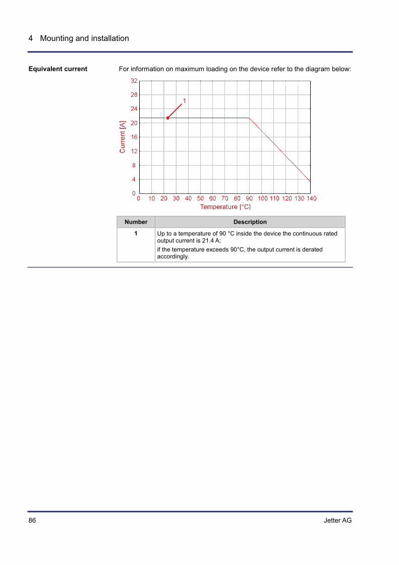
86 Jetter AG
4 Mounting and installation
For information on maximum loading on the device refer to the diagram below:
Number Description
1 Up to a temperature of 90 °C inside the device the continuous rated output current is 21.4 A; if the temperature exceeds 90°C, the output current is derated accordingly.
Equivalent current

Jetter AG 87
JCM-350-E01/E02 Mounting and installation
I²t monitoring of digital outputs
The controller JCM-350-E01/E02 monitors and limits the current of digital outputs 1 ... 8.
If the current delivered per unit of time exceeds the limit, the JCM-350-E01/E02 disables the digital outputs. The controller lets you read out the I2t value to keep track of load and temperature. You can define corrective actions to be taken if one of these values exceeds its limit, e. g. cut off the load. The diagram below shows the maximum current of the digital outputs that is allowed to flow per time t:
Number Description
1 I²t curve for a rated current of 8 A and an internal temperature of the device of 105 °C.
2 I²t curve for a rated current of 10.7 A and an internal temperature of the device of 90 °C.
Current limitation
I2t monitoring

88 Jetter AG
4 Mounting and installation
For information on maximum loading on the device resulting from digital outputs refer to the diagram below:
Number Description
1 Up to a temperature of 90 °C inside the device the continuous rated output current is 10.7 A; If the temperature inside the device exceeds 90 °C, the output current is derated accordingly.
Equivalent total current of digital outputs

Jetter AG 89
JCM-350-E01/E02 Initial commissioning
5 Initial commissioning
This chapter provides a compact description on how to commission the JCM-350-E01/E02 and covers the following functions:
Topic Page Preparatory work for initial commissioning ................................................... 90 Initial Commissioning in JetSym ................................................................... 92 Enabling the device in the application program ............................................ 98
Purpose of this chapter
Table of Contents
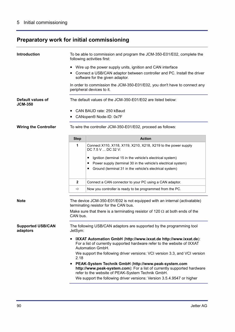
90 Jetter AG
5 Initial commissioning
Preparatory work for initial commissioning
To be able to commission and program the JCM-350-E01/E02, complete the following activities first:
Wire up the power supply units, ignition and CAN interface Connect a USB/CAN adaptor between controller and PC. Install the driver
software for the given adaptor.
In order to commission the JCM-350-E01/E02, you don't have to connect any peripheral devices to it.
The default values of the JCM-350-E01/E02 are listed below:
CAN BAUD rate: 250 kBaud CANopen® Node-ID: 0x7F
To wire the controller JCM-350-E01/E02, proceed as follows:
Step Action
1 Connect X110, X118, X119, X210, X218, X219 to the power supply DC 7.5 V ... DC 32 V:
Ignition (terminal 15 in the vehicle's electrical system) Power supply (terminal 30 in the vehicle's electrical system) Ground (terminal 31 in the vehicle's electrical system)
2 Connect a CAN connector to your PC using a CAN adaptor.
Now you controller is ready to be programmed from the PC.
The device JCM-350-E01/E02 is not equipped with an internal (activatable) terminating resistor for the CAN bus. Make sure that there is a terminating resistor of 120 Ω at both ends of the CAN bus.
The following USB/CAN adaptors are supported by the programming tool JetSym:
IXXAT Automation GmbH (http://www.ixxat.de http://www.ixxat.de): For a list of currently supported hardware refer to the website of IXXAT Automation GmbH. We support the following driver versions: VCI version 3.3, and VCI version 2.18
PEAK-System Technik GmbH (http://www.peak-system.com http://www.peak-system.com): For a list of currently supported hardware refer to the website of PEAK-System Technik GmbH. We support the following driver versions: Version 3.5.4.9547 or higher
Introduction
Default values of JCM-350
Wiring the Controller
Note
Supported USB/CAN adaptors

Jetter AG 91
JCM-350-E01/E02 Initial commissioning
Prerequisites: Before installing the USB CAN adaptor, JetSym 4.3 or higher must be installed on the PC to be used. To install the adaptor proceed as follows:
Step Action
1 Insert the USB CAN adaptor into a USB port of your PC.
2 If the Hardware Wizard opens, close it.
3 Install the driver for the USB CAN adaptor.
4 Install the corresponding JetSym driver depending on the USB CAN adaptor used.
If ... ... then ...
... you use an adaptor by PEAK-Systems
... proceed with step 5.
... you do not use an adaptor by PEAK-Systems
... proceed with step 7.
5 Navigate in Windows Explorer to the directory PcanDrv located in the JetSym installation. Default location: C:\Programme\Jetter\JetSym\Tools\PcanDrv
6 Execute the file PcanDrv.exe. Follow the steps of the installation routine.
7 Plug the Sub-D connector of the adaptor into the IN_CAN port of the JCM-350-E01/E02 (female Sub-D connector).
Result: In the case of an error-free installation the CANopen® connection between PC and controller is established.
Simultaneously pressing function keys F1 and F6 on the JCM-350-E01/E02 during power-up will prevent the application program from being launched.
Power Supply of the Device (see page 50) Initial Commissioning in JetSym (see page 92)
Installing the USB CAN adaptor
Behavior after power-up
Related topics
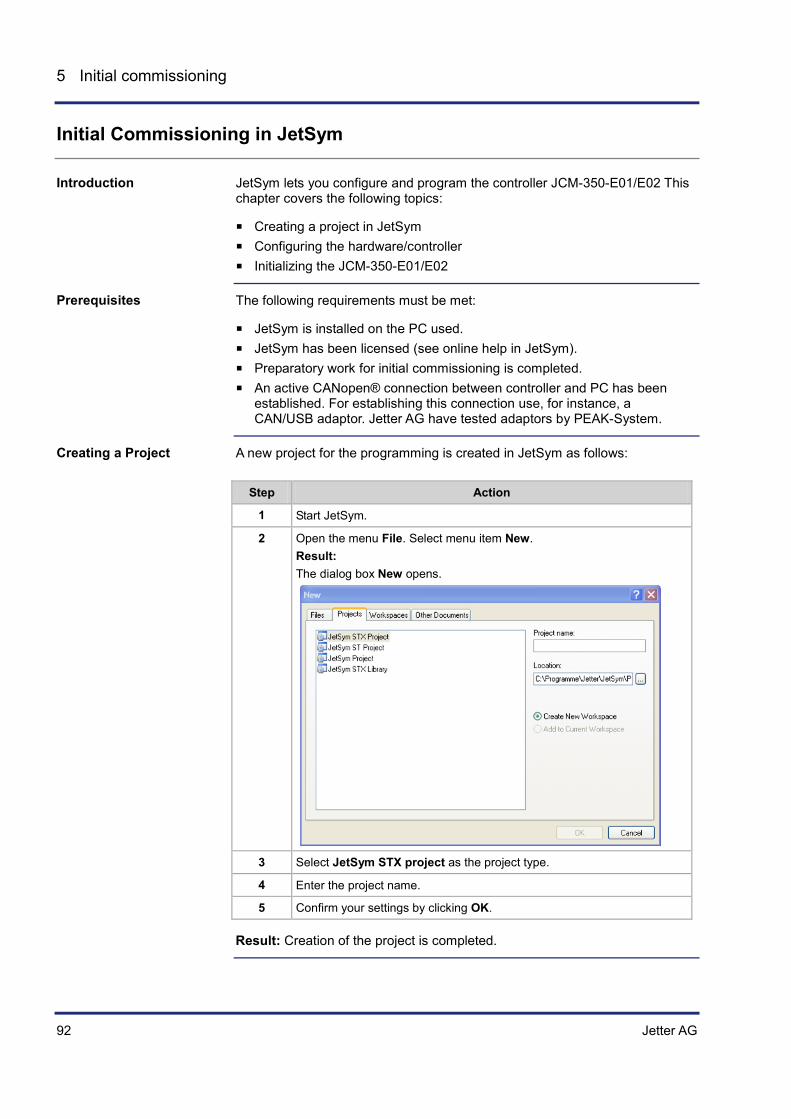
92 Jetter AG
5 Initial commissioning
Initial Commissioning in JetSym
JetSym lets you configure and program the controller JCM-350-E01/E02 This chapter covers the following topics:
Creating a project in JetSym Configuring the hardware/controller Initializing the JCM-350-E01/E02
The following requirements must be met:
JetSym is installed on the PC used. JetSym has been licensed (see online help in JetSym). Preparatory work for initial commissioning is completed. An active CANopen® connection between controller and PC has been
established. For establishing this connection use, for instance, a CAN/USB adaptor. Jetter AG have tested adaptors by PEAK-System.
A new project for the programming is created in JetSym as follows:
Step Action
1 Start JetSym.
2 Open the menu File. Select menu item New. Result: The dialog box New opens.
3 Select JetSym STX project as the project type.
4 Enter the project name.
5 Confirm your settings by clicking OK.
Result: Creation of the project is completed.
Introduction
Prerequisites
Creating a Project

Jetter AG 93
JCM-350-E01/E02 Initial commissioning
To establish a connection between JetSym and the controller, you must configure the hardware:
Step Action
1 Switch to the Hardware view by clicking on the tab with the same name.
2 Fully expand the Hardware tree.
3 Double-click on CPU. Result: The dialog box Configuration opens.
4 Under Controller/Type select JCM-350.
5 Under Interface/Type select JetCAN.
6 Test the connection to the controller by pressing the button Test. If the test fails, check the mechanical CAN connection between PC and JCM-350-E01/E02 (refer to the next topic "Possible Error Messages").
7 Save your settings using the shortcut Ctrl + S.
Result: The hardware settings are configured in JetSym.
Configuring the Hardware

94 Jetter AG
5 Initial commissioning
Error message # 1:
Possible cause
Fix for this Problem
Selection of wrong controller type
Check whether your selection matches the controller type. If it does not match the type, open the configuration dialog and re-select the controller.
Wrong Baud rate Check whether a Baud rate of 250 kBaud is set. If not, set it to 250 kBaud.
Possible Error Messages

Jetter AG 95
JCM-350-E01/E02 Initial commissioning
Possible cause
Fix for this Problem
Wrong node ID If you don't know the node ID of your controller, scan the CAN bus for nodes:
Select the hardware that has been found as a result of the scan:
Select the controller that has been found as a result of the scan:
Result: The node ID of the controller is automatically entered into the corresponding box of the configuration mask.
Error message # 2:

96 Jetter AG
5 Initial commissioning
Possible cause
Fix for this Problem
Wrong Baud rate Check whether a Baud rate of 250 kBaud is set. Where necessary, restart JetSym. Enter the correct Baud rate. Test the connection to the controller again.
Note: If this error message is displayed after the restart of JetSym, re-boot your PC.
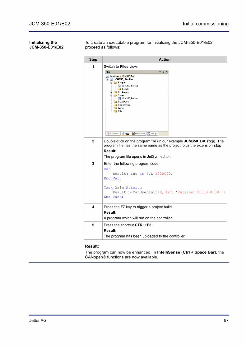
Jetter AG 97
JCM-350-E01/E02 Initial commissioning
To create an executable program for initializing the JCM-350-E01/E02, proceed as follows:
Step Action
1 Switch to Files view.
2 Double-click on the program file (in our example JCM350_BA.stxp). The program file has the same name as the project, plus the extension stxp. Result: The program file opens in JetSym editor.
3 Enter the following program code: Var Result: Int at %VL 1000000; End_Var; Task Main Autorun Result := CanOpenInit(0, 127, 'Version: 01.00.0.00'); End_Task;
4 Press the F7 key to trigger a project build. Result: A program which will run on the controller.
5 Press the shortcut CTRL+F5. Result: The program has been uploaded to the controller.
Result: The program can now be enhanced. In IntelliSense (Ctrl + Space Bar), the CANopen® functions are now available.
Initializing the JCM-350-E01/E02

98 Jetter AG
5 Initial commissioning
Enabling the device in the application program
After power-up the JCM-350-E01/E02 is ready for operation. The peripheral connections, such as digital outputs, are not yet active. You must enable the device in the application program.
The following requirements must be met:
The JCM-350-E01/E02 is connected to a power supply unit. The device is connected to the PC via CANopen® interface. A JetSym project is open or has been created.
To commission the JCM-350-E01/E02, proceed as follows:
Step Action
1 In the tree structure Files open a setup pane.
2 Enter the value 11 into R 600000401:
Communication for I/O module 1 is enabled. The setup pane lets you access all registers on I/O module 1. To enable I/O module 2, enter the value 12 into R 600000401. This enabling procedure applies only to JCM-350-E02.
Initial Commissioning in JetSym (see page 92) Status and Instructions (see page 169)
Introduction
Prerequisites
Commissioning from within the application program
Related topics

Jetter AG 99
JCM-350-E01/E02 CANopen® STX API
6 CANopen® STX API
This chapter describes the STX functions of the CANopen® STX API.
CANopen® is an open standard for networking and communication, for instance, in the automobile sector. The CANopen® protocol has been further developed by the CiA e.V. (CAN in Automation) and works on the physical layer with CAN Highspeed in accordance with ISO 11898.
The CANopen® specifications can be obtained from the CiA e.V. http://www.can-cia.org homepage. The key specification documents are:
CiA DS 301 - This document is also known as the communication profile and describes the fundamental services and protocols used under CANopen®.
CiA DS 302 - Framework for programmable devices (CANopen® Manager, SDO Manager)
CiA DR 303 - Information on cables and connectors CiA DS 4xx - These documents describe the behavior of a number of
device classes in, what are known as, device profiles.
These STX functions are used in communication between the JCM-350-E01/E02 and other CANopen® nodes.
In this chapter we use the point of view from the higher-level controller, whereas in the document CiA DS 301 the point of view from the devices is used. This is why you need, for example, a PDO-RX macro to invoke the function CanOpenAddPDORx().
In this chapter, the following terms and abbreviations are used:
Term Description
Node ID Node identification number of the device: This ID lets you address the device.
ro Read only access
rw Read/write access
Introduction
The CANopen® standard
Documentation
Application
Note: Take into account the point of view!
Terms and abbreviations:

100 Jetter AG
6 CANopen® STX API
Topic Page STX Function CanOpenInit ......................................................................... 101 STX Function CanOpenSetCommand ........................................................ 103 STX Function CanOpenUploadSDO .......................................................... 106 STX Function CanOpenDownloadSDO ....................................................... 111 STX function CanOpenAddPDORx ............................................................ 116 STX Function CanOpenAddPDOTx ........................................................... 123 Heartbeat monitoring .................................................................................. 130 CANopen® object dictionary for JCM-350-E01/E02 ................................... 134
Table of contents

Jetter AG 101
JCM-350-E01/E02 CANopen® STX API
STX Function CanOpenInit
The function CanOpenInit() lets you initialize one of the CAN busses. The JCM-350-E01/E02 then automatically sends the heartbeat message every second with the following communication object identifier (COB-ID): Node ID + 0x700.
Function CanOpenInit(
CANNo:Int,
NodeID:Int,
const ref SWVersion:String,
) :Int;
The function CanOpenInit() has got the following parameters.
Parameter Description Value
CANNo CAN bus number 0 ... CANMAX
NodeID Own node ID 1 ... 127
SWVersion Reference to own software version This software version is entered into the index 0x100A in the object directory.
String up to 255 characters
This function transfers the following return values to the higher-level program.
Return value
0 OK
-1 Error when checking parameters
-3 Initialization has not worked
The value of the CANMAX parameter depends on the device. The following table provides information on this point.
Device CANMAX
BTM 07 2
BTM 012 1 - 2
BTM 011 0
JCM-350 4
JCM-620 2
JVM-104 0
JVM-407 2
JVM-407B 2
Introduction
Function declaration
Function parameters
Return value
Parameter CANNo

102 Jetter AG
6 CANopen® STX API
Initializing the CAN-Bus 0. The JCM-350-E01/E02 has Node-ID 20 (0x14). Result := CanOpenInit(0, 20, 'Version: 01.00.0.00');
During initialization, the JCM-350-E01/E02 processes the following process steps:
Level Description
1 First, the bootup message is sent as a heartbeat message.
2 As soon as the JCM-350-E01/E02 goes into preoperational status, it sends the heartbeat message "preoperational".
If the JCM-350-E01/E02 is in "preoperational" state, it lets you access the object directory using SDO.
After initialization, NMT messages can be sent and received. The own heartbeat status can be changed with the function CanOpenSetCommand.
STX Function CanOpenSetCommand (see page 103)
How to use this function
Operating principle
Access to the object directory
NMT messages
Related topics

Jetter AG 103
JCM-350-E01/E02 CANopen® STX API
STX Function CanOpenSetCommand
The function CanOpenSetCommand() lets you change the own heartbeat status and the heartbeat status for all other devices (NMT slaves) on the CAN bus.
Function CanOpenSetCommand(
CANNo:Int,
iType:Int,
Value:Int,
) :Int;
The function CanOpenSetCommand() has got the following parameters.
Parameter Description Value
CANNo CAN bus number 0 ... CANMAX
iType Command selection See table below.
iType Description: Value
CAN_CMD_HEARTBEAT Only the own heartbeat status is changed. Selecting heartbeat states: CAN_HEARTBEAT_STOPPED (0x04) CAN_HEARTBEAT_OPERATIONAL (0x05) CAN_HEARTBEAT_PREOPERATIONAL (0x7F)
CAN_CMD_NMT The heartbeat status is changed for all other devices or for a specific device on the CAN bus. Selecting heartbeat states (NMT master): CAN_NMT_OPERATIONAL (0x01) or CAN_NMT_START (0x01) CAN_NMT_STOP (0x02) CAN_NMT_PREOPERATIONAL (0x80) CAN_NMT_RESET (0x81) CAN_NMT_RESETCOMMUNICATION (0x82)
CAN_CMD_TIME_CONSUMER
This command lets you set the device to ready-to-receive state to allow time synchronization via CAN bus (CAN ID 0x100). Refer to document by CiA e.V. DS301 V402, page 59. Enabling/disabling synchronization: CAN_TIME_CONSUMER_DISABLE = 0 CAN_TIME_CONSUMER_ENABLE = 1
CAN_CMD_TIME_PRODUCER
The time is published on the CAN bus. For more information on structure refer to document DS301 by CiA e.V., CAN ID 0x100: CAN_TIME_PRODUCER_SEND = 1 (for sending TIME_OF_DAY once)
Introduction
Function declaration
Function parameters
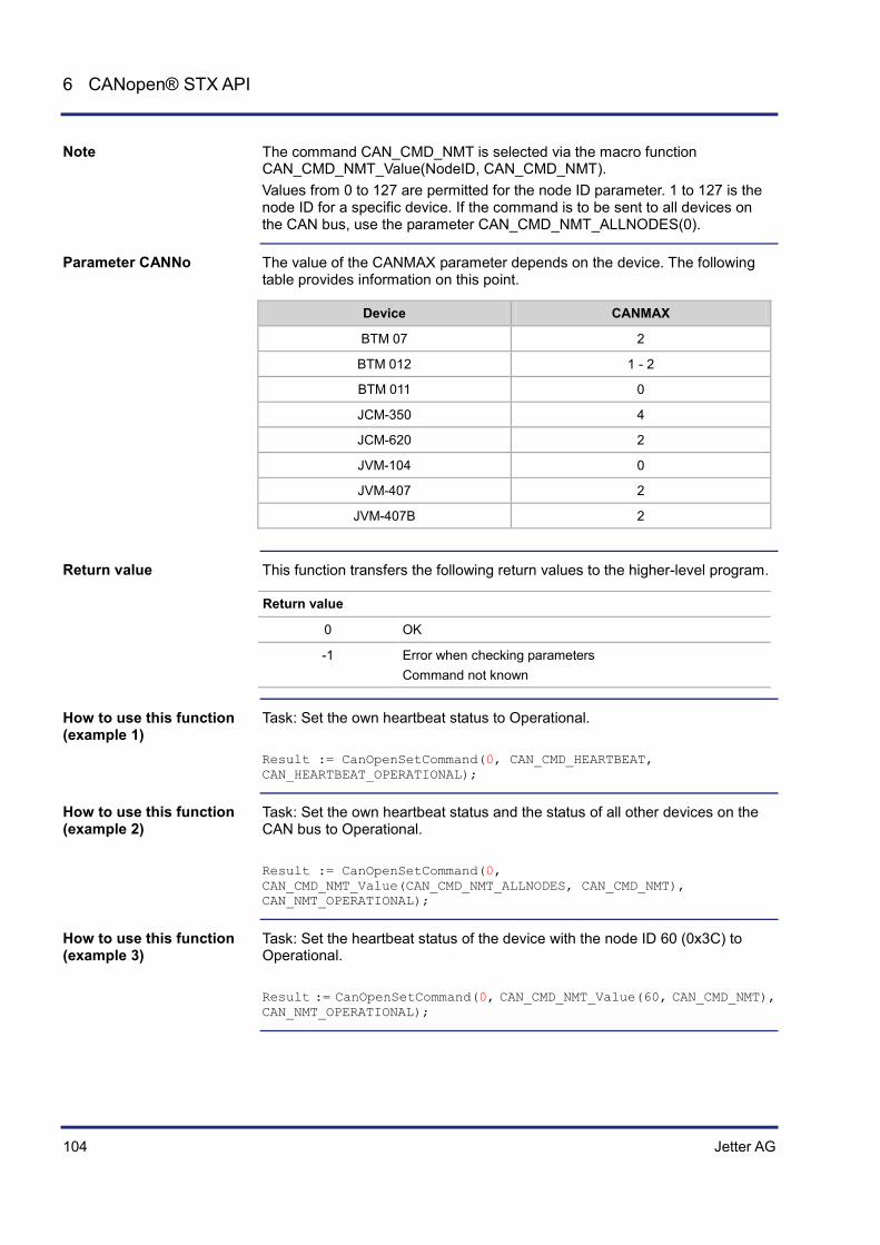
104 Jetter AG
6 CANopen® STX API
The command CAN_CMD_NMT is selected via the macro function CAN_CMD_NMT_Value(NodeID, CAN_CMD_NMT). Values from 0 to 127 are permitted for the node ID parameter. 1 to 127 is the node ID for a specific device. If the command is to be sent to all devices on the CAN bus, use the parameter CAN_CMD_NMT_ALLNODES(0).
The value of the CANMAX parameter depends on the device. The following table provides information on this point.
Device CANMAX
BTM 07 2
BTM 012 1 - 2
BTM 011 0
JCM-350 4
JCM-620 2
JVM-104 0
JVM-407 2
JVM-407B 2
This function transfers the following return values to the higher-level program.
Return value
0 OK
-1 Error when checking parameters Command not known
Task: Set the own heartbeat status to Operational. Result := CanOpenSetCommand(0, CAN_CMD_HEARTBEAT, CAN_HEARTBEAT_OPERATIONAL);
Task: Set the own heartbeat status and the status of all other devices on the CAN bus to Operational. Result := CanOpenSetCommand(0, CAN_CMD_NMT_Value(CAN_CMD_NMT_ALLNODES, CAN_CMD_NMT), CAN_NMT_OPERATIONAL);
Task: Set the heartbeat status of the device with the node ID 60 (0x3C) to Operational. Result := CanOpenSetCommand(0, CAN_CMD_NMT_Value(60, CAN_CMD_NMT), CAN_NMT_OPERATIONAL);
Note
Parameter CANNo
Return value
How to use this function (example 1)
How to use this function (example 2)
How to use this function (example 3)

Jetter AG 105
JCM-350-E01/E02 CANopen® STX API
Task: Enable time synchronization via CAN bus (CAN ID 0x100). Result := CanOpenSetCommand(0, CAN_CMD_HEARTBEAT, CAN_HEARTBEAT_OPERATIONAL);
Task: Publish the time on the CAN bus. Result := CanOpenSetCommand(0, CAN_CMD_HEARTBEAT, CAN_HEARTBEAT_OPERATIONAL);
How to use this function (example 4)
How to use this function (example 5)

106 Jetter AG
6 CANopen® STX API
STX Function CanOpenUploadSDO
The function CanOpenUploadSDO() lets you access a particular object in the Object Directory of the message recipient and read the value of the object. Data is exchanged in accordance with the SDO upload protocol. Supported transfer types are "segmented" (more than 4 data bytes) and "expedited" (up to 4 data bytes).
Function CanOpenUploadSDO (
CANNo:Int, // Number of the bus line
NodeID:Int, // Node ID
wIndex:Word,
SubIndex:Byte,
DataType:Int, // Type of the data to be received
// Volume of data for the global variable DataAddr DataLength:Int,
// Global variable holding the received value const ref DataAddr,
ref Busy: Int, // Status or the SDO transmission
) :Int;
The CanOpenUploadSDO() function has got the following parameters.
Parameter Description Value
CANNo CAN bus number 0 ... CANMAX
NodeID Node ID of the message recipient
1 ... 127
wIndex Index number of the object 0 ... 0xFFFF
SubIndex Sub-index number of the object 0 ... 255
DataType Type of data to be received 2 ... 27
DataLength Volume of data for the global variable DataAddr
DataAddr Global variable into which the received value is to be entered
Busy Status of the SDO transmission
This function transfers the following return values to the higher-level program.
Return value
0 OK
-1 Error in checking parameters
-2 Device in Stop status
-3 DataType is greater than DataLength
-4 Insufficient memory
Introduction
Function declaration
Function parameters
Return value

Jetter AG 107
JCM-350-E01/E02 CANopen® STX API
The value of the CANMAX parameter depends on the device. The following table provides information on this point.
Device CANMAX
BTM 07 2
BTM 012 1 - 2
BTM 011 0
JCM-350 4
JCM-620 2
JVM-104 0
JVM-407 2
JVM-407B 2
The following data types can be received.
Byte types CANopen® format Jetter format
1 CANOPEN_INTEGER8 CANOPEN_UNSIGNED8
Byte
2 CANOPEN_INTEGER16 CANOPEN_UNSIGNED16
Word
3 CANOPEN_INTEGER24 CANOPEN_UNSIGNED24
-
4 CANOPEN_INTEGER32 CANOPEN_UNSIGNED32 CANOPEN_REAL
Int
5 CANOPEN_INTEGER40 CANOPEN_UNSIGNED40
-
6 CANOPEN_INTEGER48 CANOPEN_UNSIGNED48 CANOPEN_TIME_OF_DAY CANOPEN_TIME_DIFFERENCE
-
7 CANOPEN_INTEGER56 CANOPEN_UNSIGNED46
-
8 CANOPEN_INTEGER64 CANOPEN_UNSIGNED64 CANOPEN_REAL64
-
n CANOPEN_VISIBLE_STRING CANOPEN_OCTET_STRING CANOPEN_UNICODE_STRING CANOPEN_DOMAIN
String
Parameter CANNo
Parameter DataType

108 Jetter AG
6 CANopen® STX API
After calling up the function, the Busy parameter is set to SDOACCESS_INUSE. With an error in transmission, Busy is set to SDOACCESS_ERROR. With a successful transmission, the number of bytes transmitted is returned.
With an error in transmission, Busy returns an error code. The following error codes are available: SDOACCESS_STILLUSED Another task is communicating with the same node ID. SDOACCESS_TIMEOUT The task has been timed out because the device with the specified node ID is not responding. If the specified node ID does not respond within 1 second, the timeout bit is set. SDOACCESS_ILLCMD The response to the request is invalid. SDOACCESS_ABORT Access to the device with the specified node ID was aborted. SDOACCESS_SYSERROR General internal error
The following macros have been defined in connection with this function: SDOACCESS_FINISHED (busy) This macro checks whether communication has finished. SDOACCESS_ERROR (busy) This macro checks whether an error has occurred.
Result := CanOpenUploadSDO(
0, // CANNo
66, // NodeID
0x100A, // wIndex
0, // SubIndex
CANOPEN_STRING, // DataType
sizeof(var_Versionstring), // DataLength
var_Versionstring, // DataAddr
busy); // Busy
Busy
"Busy" Error Codes
Macro Definitions
How to use this function

Jetter AG 109
JCM-350-E01/E02 CANopen® STX API
In the following example, the manufacturer's software version is read from the CANopen® Object Directory of the device with the addressed node ID.
Const
CANNo = 0; // Number of the bus line
NodeID_Node_0 = 10; // Device ID of node 1
NodeID_Node_1 = 66; // Device ID of node 2
End_Const;
Var
busy: Int;
Version string: String;
Objectindex: Word;
Subindex: Byte;
End_Var;
Task main autorun
Var
SW_Version: String;
End_Var;
SW_Version := 'v4.3.0.2004';
// Initializing CAN 0 CanOpenInit(CANNo, // Number of the bus line
NodeID_Node_0, // Node ID
SW_Version); // Manufacturer's software version
// All devices on the CAN bus have the status of PREOPERATIONAL
// Request manufacturer's software version per SDO Objectindex := 0x100A;
Subindex := 0;
CanOpenUploadSDO(CANNo, // Number of the bus line
NodeID_Node_1, // Node ID
Objectindex, // wIndex
Subindex, // SubIndex
CANOPEN_STRING, // DataType
sizeof(Versionstring), // DataLength
Versionstring, // DataAddr
busy); // Busy
// Waiting until communication is completed When SDOACCESS_FINISHED(busy) Continue;
// Checking for errors If (SDOACCESS_ERROR(busy)) Then
// Troubleshooting
JetSym STX program

110 Jetter AG
6 CANopen® STX API
End_If;
// ... // ... // ...
End_Task;

Jetter AG 111
JCM-350-E01/E02 CANopen® STX API
STX Function CanOpenDownloadSDO
The function CanOpenDownloadSDO() lets you access a particular object in the Object Directory of the message recipient and specify the value of the object. Data is exchanged in accordance with the SDO upload protocol. Supported transfer types are "segmented" or "block" (more than 4 data bytes) and "expedited" (up to 4 data bytes).
Function CanOpenDownloadSDO(
CANNo:Int, // Number of the bus line
NodeID:Int, // Node ID
wIndex:Word,
SubIndex:Byte,
DataType:Int, // Type of the data to be sent
// Volume of data for the global variable DataAddr DataLength:Int,
// Global variable holding the value to be sent const ref DataAddr,
ref Busy: Int, // Status or the SDO transmission
) :Int;
The CanOpenDownloadSDO() function has got the following parameters.
Parameter Description Value
CANNo CAN bus number 0 ... CANMAX
NodeID Node ID of the message recipient 1 ... 127
wIndex Index number of the object 0 ... 0xFFFF
SubIndex Sub-index number of the object 0 ... 255
DataType Type of data to be sent 2 ... 27
DataLength Volume of data for the global variable DataAddr
DataAddr Global variable into which the value to be sent is to be entered
Busy Status of the SDO transmission
This function transfers the following return values to the higher-level program.
Return value
0 OK
-1 Error when checking parameters
-2 Device in Stop status (own heartbeat status)
-3 DataType is greater than DataLength
-4 Insufficient memory
Introduction
Function declaration
Function parameters
Return value

112 Jetter AG
6 CANopen® STX API
The value of the CANMAX parameter depends on the device. The following table provides information on this point.
Device CANMAX
BTM 07 2
BTM 012 1 - 2
BTM 011 0
JCM-350 4
JCM-620 2
JVM-104 0
JVM-407 2
JVM-407B 2
The following data types can be received.
Byte types CANopen® format Jetter format
1 CANOPEN_INTEGER8 CANOPEN_UNSIGNED8
Byte
2 CANOPEN_INTEGER16 CANOPEN_UNSIGNED16
Word
3 CANOPEN_INTEGER24 CANOPEN_UNSIGNED24
-
4 CANOPEN_INTEGER32 CANOPEN_UNSIGNED32 CANOPEN_REAL
Int
5 CANOPEN_INTEGER40 CANOPEN_UNSIGNED40
-
6 CANOPEN_INTEGER48 CANOPEN_UNSIGNED48 CANOPEN_TIME_OF_DAY CANOPEN_TIME_DIFFERENCE
-
7 CANOPEN_INTEGER56 CANOPEN_UNSIGNED46
-
8 CANOPEN_INTEGER64 CANOPEN_UNSIGNED64 CANOPEN_REAL64
-
n CANOPEN_VISIBLE_STRING CANOPEN_OCTET_STRING CANOPEN_UNICODE_STRING CANOPEN_DOMAIN
String
Parameter CANNo
Parameter DataType

Jetter AG 113
JCM-350-E01/E02 CANopen® STX API
After calling up the function, the Busy parameter is set to SDOACCESS_INUSE. With an error in transmission, Busy is set to SDOACCESS_ERROR. With a successful transmission, the number of bytes transmitted is returned.
With an error in transmission, Busy returns an error code. The following error codes are available: SDOACCESS_STILLUSED Another task is communicating with the same node ID. SDOACCESS_TIMEOUT The task has been timed out because the device with the given node ID is not responding. If the specified node ID does not respond within 1 second, the timeout bit is set. SDOACCESS_ILLCMD The response to the request is invalid. SDOACCESS_ABORT Access to the device with the specified node ID was aborted. SDOACCESS_BLKSIZEINV Communication error with Block Download SDOACCESS_SYSERROR General internal error
The following macros have been defined in connection with this function: SDOACCESS_FINISHED (busy) This macro checks whether communication has finished. SDOACCESS_ERROR (busy) This macro checks whether an error has occurred.
Result := CanOpenDownloadSDO(
0, // CANNo
68, // NodeID
0x1017, // wIndex
0, // SubIndex
CANOPEN_WORD, // DataType
sizeof(var_Heartbeat_time), // DataLength
var_Heartbeat_time, // DataAddr
busy); // Busy
Busy
"Busy" Error Codes
Macro Definitions
How to use this function
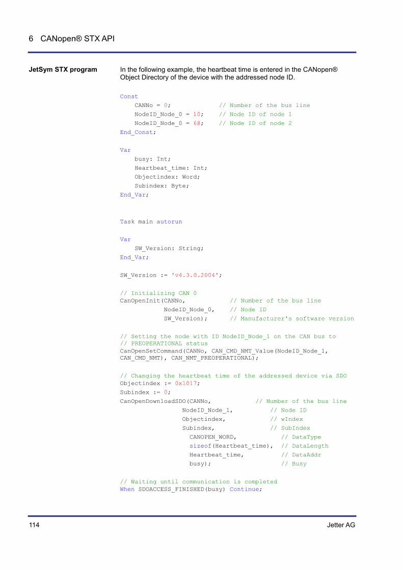
114 Jetter AG
6 CANopen® STX API
In the following example, the heartbeat time is entered in the CANopen® Object Directory of the device with the addressed node ID. Const
CANNo = 0; // Number of the bus line
NodeID_Node_0 = 10; // Node ID of node 1
NodeID_Node_0 = 68; // Node ID of node 2
End_Const;
Var
busy: Int;
Heartbeat_time: Int;
Objectindex: Word;
Subindex: Byte;
End_Var;
Task main autorun
Var
SW_Version: String;
End_Var;
SW_Version := 'v4.3.0.2004';
// Initializing CAN 0 CanOpenInit(CANNo, // Number of the bus line
NodeID_Node_0, // Node ID
SW_Version); // Manufacturer's software version
// Setting the node with ID NodeID_Node_1 on the CAN bus to // PREOPERATIONAL status CanOpenSetCommand(CANNo, CAN_CMD_NMT_Value(NodeID_Node_1, CAN_CMD_NMT), CAN_NMT_PREOPERATIONAL);
// Changing the heartbeat time of the addressed device via SDO Objectindex := 0x1017;
Subindex := 0;
CanOpenDownloadSDO(CANNo, // Number of the bus line
NodeID_Node_1, // Node ID
Objectindex, // wIndex
Subindex, // SubIndex
CANOPEN_WORD, // DataType
sizeof(Heartbeat_time), // DataLength
Heartbeat_time, // DataAddr
busy); // Busy
// Waiting until communication is completed When SDOACCESS_FINISHED(busy) Continue;
JetSym STX program

Jetter AG 115
JCM-350-E01/E02 CANopen® STX API
// Checking for errors If (SDOACCESS_ERROR(busy)) Then
// Troubleshooting End_If;
// Resetting all devices on the CAN bus to OPERATIONAL status CanOpenSetCommand(CANNo, CAN_CMD_NMT_Value(CAN_CMD_NMT_ALLNODES, CAN_CMD_NMT), CAN_NMT_OPERATIONAL);
// ... // ... // ...
End_Task;

116 Jetter AG
6 CANopen® STX API
STX function CanOpenAddPDORx
By calling up the CanOpenAddPDORx() function, process data, sent by other CANopen® devices, can be entered on receipt. Process data can be received only when a CANopen® device is sending them.
Only if the CANopen® devices on the bus are in state "operational", the PDO telegram is transmitted.
The smallest time unit for the Event Time is 1 ms. The smallest time unit for the Inhibit Time is 1 ms.
Function CanOpenAddPDORx(
CANNo:Int, // Number of the bus line
CANID:Int, // CAN identifier
// Starting position of the data to be received BytePos:Int,
DataType:Int, // Data type of the data to be received
// Volume of data for the global variable VarAddr DataLength:Int,
// Global variable holding the received value const ref VarAddr,
// Cycle time for receiving telegrams (Event Time) EventTime: Int,
// Minimum time lag between two telegrams received // (Inhibit Time) InhibitTime: Int,
Paramset: Int, // Bit-coded parameter
) :Int;
The CanOpenAddPDORx() function has got the following parameters:
Parameter Description Value
CANNo CAN bus number 0 ... CANMAX
CANID CAN identifier 11-bit CAN identifier 29-bit
0 ... 0x7FF 0 ... 0x1FFFFFFF
BytePos Starting position of data to be received
0 ... 7
DataType Data type of data to be received 2 ... 13, 15 ... 27
DataLength Volume of data for the global variable VarAddr
VarAddr Global variable into which the received value is entered
EventTime Time lag between two telegrams (> Inhibit Time)
InhibitTime Minimum time lag between two telegrams received (< EventTime)
Introduction
Notes
Function declaration
Function parameters

Jetter AG 117
JCM-350-E01/E02 CANopen® STX API
Parameter Description Value
Paramset Bit-coded parameter
This function transfers the following return values to the higher-level program.
Return value
0 OK
-1 Error when checking parameters
-3 DataType is greater than DataLength
-4 Insufficient memory
The value of the CANMAX parameter depends on the device. The following table provides information on this point.
Device CANMAX
BTM 07 2
BTM 012 1 - 2
BTM 011 0
JCM-350 4
JCM-620 2
JVM-104 0
JVM-407 2
JVM-407B 2
In this chapter we use the point of view from the higher-level controller, whereas in the document CiA DS 301 the point of view from the devices is used. This is why you need a PDO-RX macro to invoke the function CanOpenAddPDORx() from the controller.
Return value
Parameter CANNo
Note: Take into account the point of view!

118 Jetter AG
6 CANopen® STX API
The CANID parameter is used to transfer the CAN identifier. The CAN identifier is generated with a macro. The CAN identifier depends on the node ID of the other communicating user and on whether it is a PDO1, PDO2, PDO3 or PDO4 message. Macro definitions: #Define CANOPEN_PDO1_RX (NodeID) ((NodeID) + 0x180) #Define CANOPEN_PDO2_RX (NodeID) ((NodeID) + 0x280) #Define CANOPEN_PDO3_RX (NodeID) ((NodeID) + 0x380) #Define CANOPEN_PDO4_RX (NodeID) ((NodeID) + 0x480) #Define CANOPEN_PDO1_TX (NodeID) ((NodeID) + 0x200) #Define CANOPEN_PDO2_TX (NodeID) ((NodeID) + 0x300) #Define CANOPEN_PDO3_TX (NodeID) ((NodeID) + 0x400) #Define CANOPEN_PDO4_TX (NodeID) ((NodeID) + 0x500) Example for calling up the macro: CANOPEN_PDO2_RX (64) The resulting CAN identifier is: 2C0h = 40h + 280h
For CANopen® the following CAN identifier distribution is predefined. In this case, the node number is embedded in the identifier.
11-bit identifier (binary)
Identifier (decimal)
Identifier (hexadecimal
Description
000000000000 0 0 Network Management
000100000000 128 80h Synchronization
0001xxxxxxxx 129 - 255 81h - FFh Emergency
0011xxxxxxxx 385 - 511 181h - 1FFh PDO1 (tx)
0100xxxxxxxx 513 - 639 201h - 27Fh PDO1 (rx)
0101xxxxxxxx 641 - 767 281h - 2FFh PDO2 (tx)
0110xxxxxxxx 769 - 895 301h - 37Fh PDO2 (rx)
0111xxxxxxxx 897 - 1023 381h - 3FFh PDO3 (tx)
1000xxxxxxxx 1025 - 1151 401h -47Fh PDO3 (rx)
1001xxxxxxxx 1153 - 1279 481h - 4FFh PDO4 (tx)
1010xxxxxxxx 1281 - 1407 501h - 57Fh PDO4 (rx)
1011xxxxxxxx 1409 - 1535 581h - 5FFh Send SDO
1100xxxxxxxx 1537 - 1663 601h - 67Fh Receive SDO
1110xxxxxxxx 1793 - 1919 701h - 77Fh NMT Error Control
xxxxxxxx = Node number 1 - 127
Parameter CANID
Default CAN Identifier Distribution

Jetter AG 119
JCM-350-E01/E02 CANopen® STX API
The following data types can be received.
Byte types CANopen® format Jetter format
1 CANOPEN_INTEGER8 CANOPEN_UNSIGNED8
Byte
2 CANOPEN_INTEGER16 CANOPEN_UNSIGNED16
Word
3 CANOPEN_INTEGER24 CANOPEN_UNSIGNED24
-
4 CANOPEN_INTEGER32 CANOPEN_UNSIGNED32 CANOPEN_REAL
Int
5 CANOPEN_INTEGER40 CANOPEN_UNSIGNED40
-
6 CANOPEN_INTEGER48 CANOPEN_UNSIGNED48 CANOPEN_TIME_OF_DAY CANOPEN_TIME_DIFFERENCE
-
7 CANOPEN_INTEGER56 CANOPEN_UNSIGNED46
-
8 CANOPEN_INTEGER64 CANOPEN_UNSIGNED64 CANOPEN_REAL64
-
n CANOPEN_VISIBLE_STRING CANOPEN_OCTET_STRING CANOPEN_UNICODE_STRING CANOPEN_DOMAIN
String
The following parameters can be transferred to the function. Several parameters can be linked together using the Or function. CANOPEN_ASYNCPDORTRONLY Receive asynchronous PDOs by sending an RTR frame to the sender (after each expired EventTime). If there is no response to RTR frames, the request time increases to five times the EventTime. CANOPEN_ASYNCPDO Receive asynchronous PDOs. CANOPEN_PDOINVALID PDO not received. Disk space is reserved. CANOPEN_NORTR PDO cannot be requested by RTR (Remote Request).
Parameter DataType
Parameter Paramset

120 Jetter AG
6 CANopen® STX API
Only if CANOPEN_ASYNCPDORTROnly has been set, an RTR is sent. CANOPEN_29BIT Use 29-bit identifier Default: 11-bit identifier
Result := CanOpenAddPDORx(
0, // CANNo
662, // CANID
0, // BytePos
CANOPEN_DWORD, // DataType
sizeof(var_Data_1_of_Node_1), // DataLength
var_Data_1_of_Node_1, // VarAddr
1000, // Event time
10, // Inhibit time
CANOPEN_ASYNCPDO | CANOPEN_NORTR); // Paramset
JCM-350-E01/E02 with node ID 10 wants to receive a PDO from two CANopen® devices with node ID 64 and 102. The function CanOpenAddPDORx() is called up for this purpose. After running the program, the JCM-350-E01/E02 receives cyclic PDO telegrams.
120 Ohm 120 Ohm
CAN-Bus
CAN 0
NodeID_Node_0 NodeID_Node_2 NodeID_Node_1
Controller/HMI Device/Module Device/Module
Const
CANNo = 0; // Number of the bus line
NodeID_Node_0 = 10; // Device ID of node 1
NodeID_Node_1 = 64; // Device ID of node 2
NodeID_Node_2 = 102; // Device ID of node 3
Event_Time = 1000; // Event time in ms
Inhibit_Time = 10; // Inhibit time in ms
End_Const;
How to use this function
JetSym STX program

Jetter AG 121
JCM-350-E01/E02 CANopen® STX API
Var
Data_1_of_Node_1: Int;
Data_2_of_Node_1: Int;
Data_1_of_Node_2: Int;
End_Var;
Task main autorun
Var
SW_Version: String;
End_Var;
SW_Version := 'v4.3.0.2004';
// Initializing CAN 0 CanOpenInit(CANNo, // Number of the bus line
NodeID_Node_0, // Node ID
SW_Version); // Manufacturer's software version
// Entering process data to be sent CanOpenAddPDORx(
CANNo, // Number of the bus line
CANOPEN_PDO2_RX(NodeID_Node_1), // CANID
0, // BytePos
CANOPEN_DWORD, // DataType
sizeof(Data_1_of_Node_1), // DataLength
Data_1_of_Node_1, // VarAddr
Event_Time, // Event time
Inhibit_Time, // Inhibit time
CANOPEN_ASYNCPDORTRONLY); // Paramset
CanOpenAddPDORx(
CANNo, // Number of the bus line
CANOPEN_PDO2_RX(NodeID_Node_1), // CANID
4, // BytePos
CANOPEN_DWORD, // DataType
sizeof(Data_2_of_Node_1), // DataLength
Data_2_of_Node_1, // VarAddr
Event_Time, // Event time
Inhibit_Time, // Inhibit time
CANOPEN_ASYNCPDORTRONLY); // Paramset
CanOpenAddPDORx(
CANNo, // Number of the bus line
CANOPEN_PDO3_RX(NodeID_Node_2), // CANID
0, // BytePos
CANOPEN_BYTE, // DataType
sizeof(Data_1_of_Node_2), // DataLength

122 Jetter AG
6 CANopen® STX API
Data_1_of_Node_2, // VarAddr
Event_Time, // Event time
Inhibit_Time, // Inhibit time
CANOPEN_ASYNCPDO | CANOPEN_NORTR); // Paramset
// All devices on the CAN bus have the status of PREOPERATIONAL
// Setting all devices on the CAN bus to OPERATIONAL status CanOpenSetCommand(CANNo, CAN_CMD_NMT_Value(CAN_CMD_NMT_ALLNODES, CAN_CMD_NMT), CAN_NMT_START);
// As of now, PDO telegrams are received/sent from the higher-level // controller // ... // ... // ...
End_Task;

Jetter AG 123
JCM-350-E01/E02 CANopen® STX API
STX Function CanOpenAddPDOTx
By calling up the CanOpenAddPDOTx() function, process data can be deposited on the bus. However, that should not mean that other CANopen® devices on the bus can also read this process data.
Only if the CANopen® devices on the bus are in state "operational", the PDO telegram is transmitted.
As soon as there are any changes to the process data, another PDO telegram is transmitted immediately.
The smallest time unit for the Event Time is 1 ms. The smallest time unit for the Inhibit Time is 1 ms. Any unused bytes of a telegram are sent as null.
Function CanOpenAddPDOTx(
CANNo:Int, // Number of the bus line
CANID:Int, // CAN identifier
BytePos:Int, // Starting position of the data to be sent
DataType:Int, // Data type of the data to be sent
// Volume of data for the global variable VarAddr DataLength:Int,
// Global variable holding the value to be sent const ref VarAddr,
// Cycle time for sending telegrams (Event Time) EventTime: Int,
// Minimum time lag between two telegrams to be sent // (Inhibit Time) InhibitTime: Int,
Paramset: Int, // Bit-coded parameter
) :Int;
The CanOpenAddPDOTx() function has got the following parameters:
Parameter Description Value
CANNo CAN bus number 0 ... CANMAX
CANID CAN identifier 11-bit CAN identifier 29-bit
0 ... 0x7FF 0 ... 0x1FFFFFFF
BytePos Starting position of data to be sent
0 ... 7
DataType Data type of data to be sent 2 ... 13, 15 ... 27
DataLength Volume of data for the global variable VarAddr
VarAddr Global variable into which the value to be sent is entered
Introduction
Notes
Function declaration
Function parameters
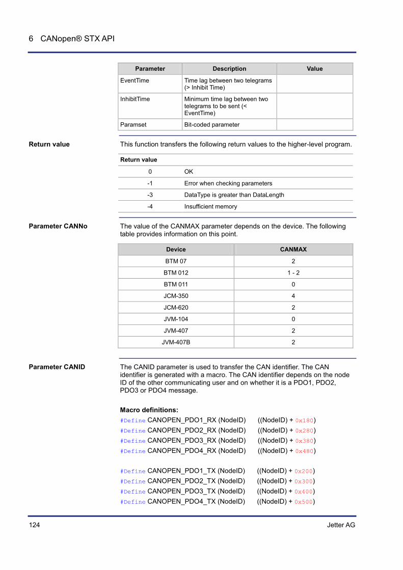
124 Jetter AG
6 CANopen® STX API
Parameter Description Value
EventTime Time lag between two telegrams (> Inhibit Time)
InhibitTime Minimum time lag between two telegrams to be sent (< EventTime)
Paramset Bit-coded parameter
This function transfers the following return values to the higher-level program.
Return value
0 OK
-1 Error when checking parameters
-3 DataType is greater than DataLength
-4 Insufficient memory
The value of the CANMAX parameter depends on the device. The following table provides information on this point.
Device CANMAX
BTM 07 2
BTM 012 1 - 2
BTM 011 0
JCM-350 4
JCM-620 2
JVM-104 0
JVM-407 2
JVM-407B 2
The CANID parameter is used to transfer the CAN identifier. The CAN identifier is generated with a macro. The CAN identifier depends on the node ID of the other communicating user and on whether it is a PDO1, PDO2, PDO3 or PDO4 message. Macro definitions: #Define CANOPEN_PDO1_RX (NodeID) ((NodeID) + 0x180) #Define CANOPEN_PDO2_RX (NodeID) ((NodeID) + 0x280) #Define CANOPEN_PDO3_RX (NodeID) ((NodeID) + 0x380) #Define CANOPEN_PDO4_RX (NodeID) ((NodeID) + 0x480) #Define CANOPEN_PDO1_TX (NodeID) ((NodeID) + 0x200) #Define CANOPEN_PDO2_TX (NodeID) ((NodeID) + 0x300) #Define CANOPEN_PDO3_TX (NodeID) ((NodeID) + 0x400) #Define CANOPEN_PDO4_TX (NodeID) ((NodeID) + 0x500)
Return value
Parameter CANNo
Parameter CANID

Jetter AG 125
JCM-350-E01/E02 CANopen® STX API
Example for calling up the macro: CANOPEN_PDO2_RX (64) The resulting CAN identifier is: 2C0h = 40h + 280h
For CANopen® the following CAN identifier distribution is predefined. In this case, the node number is embedded in the identifier.
11-bit identifier (binary)
Identifier (decimal)
Identifier (hexadecimal
Description
000000000000 0 0 Network Management
000100000000 128 80h Synchronization
0001xxxxxxxx 129 - 255 81h - FFh Emergency
0011xxxxxxxx 385 - 511 181h - 1FFh PDO1 (tx)
0100xxxxxxxx 513 - 639 201h - 27Fh PDO1 (rx)
0101xxxxxxxx 641 - 767 281h - 2FFh PDO2 (tx)
0110xxxxxxxx 769 - 895 301h - 37Fh PDO2 (rx)
0111xxxxxxxx 897 - 1023 381h - 3FFh PDO3 (tx)
1000xxxxxxxx 1025 - 1151 401h -47Fh PDO3 (rx)
1001xxxxxxxx 1153 - 1279 481h - 4FFh PDO4 (tx)
1010xxxxxxxx 1281 - 1407 501h - 57Fh PDO4 (rx)
1011xxxxxxxx 1409 - 1535 581h - 5FFh Send SDO
1100xxxxxxxx 1537 - 1663 601h - 67Fh Receive SDO
1110xxxxxxxx 1793 - 1919 701h - 77Fh NMT Error Control
xxxxxxxx = Node number 1 - 127
The following data types can be received.
Byte types CANopen® format Jetter format
1 CANOPEN_INTEGER8 CANOPEN_UNSIGNED8
Byte
2 CANOPEN_INTEGER16 CANOPEN_UNSIGNED16
Word
3 CANOPEN_INTEGER24 CANOPEN_UNSIGNED24
-
4 CANOPEN_INTEGER32 CANOPEN_UNSIGNED32 CANOPEN_REAL
Int
5 CANOPEN_INTEGER40 CANOPEN_UNSIGNED40
-
Default CAN Identifier Distribution
Parameter DataType

126 Jetter AG
6 CANopen® STX API
Byte types CANopen® format Jetter format
1 CANOPEN_INTEGER8 CANOPEN_UNSIGNED8
Byte
6 CANOPEN_INTEGER48 CANOPEN_UNSIGNED48 CANOPEN_TIME_OF_DAY CANOPEN_TIME_DIFFERENCE
-
7 CANOPEN_INTEGER56 CANOPEN_UNSIGNED46
-
8 CANOPEN_INTEGER64 CANOPEN_UNSIGNED64 CANOPEN_REAL64
-
n CANOPEN_VISIBLE_STRING CANOPEN_OCTET_STRING CANOPEN_UNICODE_STRING CANOPEN_DOMAIN
String
The following parameters can be transferred to the function. Several parameters can be linked together using the Or function. CANOPEN_ASYNCPDORTRONLY Send asynchronous PDOs by receiving an RTR frame. This feature is not yet supported at the moment. CANOPEN_ASYNCPDO Send asynchronous PDO. CANOPEN_PDOINVALID PDO not sent. The required disk space is reserved. CANOPEN_NORTR PDO cannot be requested by RTR (Remote Request). CANOPEN_29BIT Use 29-bit identifier Default: 11-bit identifier
Result := CanOpenAddPDOTx(
0, // CANNo
842, // CANID
0, // BytePos
CANOPEN_DWORD, // DataType
sizeof(var_Data_1_of_Node_3), // DataLength
var_Data_1_of_Node_3, // VarAddr
1000, // Event time
Parameter Paramset
How to use this function

Jetter AG 127
JCM-350-E01/E02 CANopen® STX API
100, // Inhibit time
CANOPEN_ASYNCPDO | CANOPEN_NORTR); // Paramset
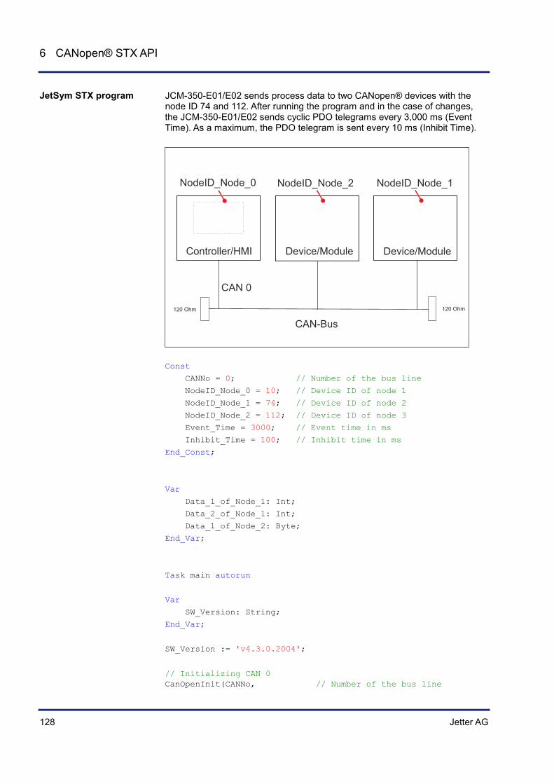
128 Jetter AG
6 CANopen® STX API
JCM-350-E01/E02 sends process data to two CANopen® devices with the node ID 74 and 112. After running the program and in the case of changes, the JCM-350-E01/E02 sends cyclic PDO telegrams every 3,000 ms (Event Time). As a maximum, the PDO telegram is sent every 10 ms (Inhibit Time).
120 Ohm 120 Ohm
CAN-Bus
CAN 0
NodeID_Node_0 NodeID_Node_2 NodeID_Node_1
Controller/HMI Device/Module Device/Module
Const
CANNo = 0; // Number of the bus line
NodeID_Node_0 = 10; // Device ID of node 1
NodeID_Node_1 = 74; // Device ID of node 2
NodeID_Node_2 = 112; // Device ID of node 3
Event_Time = 3000; // Event time in ms
Inhibit_Time = 100; // Inhibit time in ms
End_Const;
Var
Data_1_of_Node_1: Int;
Data_2_of_Node_1: Int;
Data_1_of_Node_2: Byte;
End_Var;
Task main autorun
Var
SW_Version: String;
End_Var;
SW_Version := 'v4.3.0.2004';
// Initializing CAN 0 CanOpenInit(CANNo, // Number of the bus line
JetSym STX program
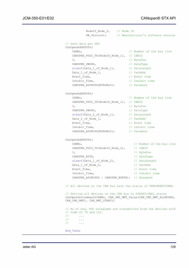
Jetter AG 129
JCM-350-E01/E02 CANopen® STX API
NodeID_Node_0, // Node ID
SW_Version); // Manufacturer's software version
// Send data per PDO CanOpenAddPDOTx(
CANNo, // Number of the bus line
CANOPEN_PDO2_TX(NodeID_Node_1), // CANID
0, // BytePos
CANOPEN_DWORD, // DataType
sizeof(Data_1_of_Node_1), // DataLength
Data_1_of_Node_1, // VarAddr
Event_Time, // Event time
Inhibit_Time, // Inhibit time
CANOPEN_ASYNCPDORTRONLY); // Paramset
CanOpenAddPDOTx(
CANNo, // Number of the bus line
CANOPEN_PDO2_TX(NodeID_Node_1), // CANID
4, // BytePos
CANOPEN_DWORD, // DataType
sizeof(Data_2_of_Node_1), // DataLength
Data_2_of_Node_1, // VarAddr
Event_Time, // Event time
Inhibit_Time, // Inhibit time
CANOPEN_ASYNCPDORTRONLY); // Paramset
CanOpenAddPDOTx(
CANNo, // Number of the bus line
CANOPEN_PDO3_TX(NodeID_Node_2), // CANID
0, // BytePos
CANOPEN_BYTE, // DataType
sizeof(Data_1_of_Node_2), // DataLength
Data_1_of_Node_2, // VarAddr
Event_Time, // Event time
Inhibit_Time, // Inhibit time
CANOPEN_ASYNCPDO | CANOPEN_NORTR); // Paramset
// All devices on the CAN bus have the status of PREOPERATIONAL
// Setting all devices on the CAN bus to OPERATIONAL status CanOpenSetCommand(CANNo, CAN_CMD_NMT_Value(CAN_CMD_NMT_ALLNODES, CAN_CMD_NMT), CAN_NMT_START);
// As of now, PDO telegrams are transmitted from the devices with // node ID 74 and 112. // ... // ... // ...
End_Task;

130 Jetter AG
6 CANopen® STX API
Heartbeat monitoring
The heartbeat protocol is for monitoring the activity of communication partners. If the inactivity exceeds the set interval (Heartbeat consumer time), the status is set to "offline". The application program lets you define heartbeat functions, such as
Displaying information to the user Rebooting the device Ignoring process data
Heartbeat monitoring is available only for specific devices and its availability depends on the OS version.
Device OS version
FMC-01 1.18.1.00 or higher
JVM-C02 4.00.0.00 or higher
JCM-350 1.09.0.215 or higher
JCM-620 JVER bersion 3.2.2.645 and JetVM version 3.04.0.00 or higher
Heartbeat monitoring uses the following registers:
Register Description Data type Attributes
40x001 Own heartbeat status of the device; value range: 0 = Bootup 4 = Stopped 5 = Operational 127 = Preoperational 255 = Offline (default value)
Int ro (read only)
40x100 The heartbeat status of all monitored node IDs has changed. Value range: 0 = False 1 = True
Bool rw (read and write)
40x101 ... 40x227
Heartbeat status of nodes with ID 1 ... 127; value range: 0 = Bootup 4 = Stopped 5 = Operational 127 = Preoperational 255 = Offline (default value)
Byte ro
40x229 ... 40x355
Heartbeat timeout of nodes with ID 1 ... 127; value range: 0 ... 65535 [ms]
Word rw
In the register number, the letter "x" represents the number of the CAN bus line used: x = 0 ... CANMAX.
Introduction
Prerequisites
Registers for heartbeat monitoring
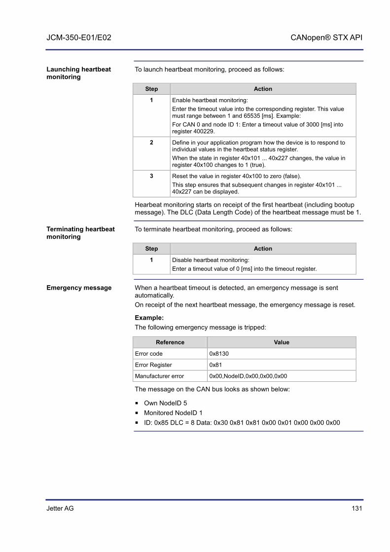
Jetter AG 131
JCM-350-E01/E02 CANopen® STX API
To launch heartbeat monitoring, proceed as follows:
Step Action
1 Enable heartbeat monitoring: Enter the timeout value into the corresponding register. This value must range between 1 and 65535 [ms]. Example: For CAN 0 and node ID 1: Enter a timeout value of 3000 [ms] into register 400229.
2 Define in your application program how the device is to respond to individual values in the heartbeat status register. When the state in register 40x101 ... 40x227 changes, the value in register 40x100 changes to 1 (true).
3 Reset the value in register 40x100 to zero (false). This step ensures that subsequent changes in register 40x101 ... 40x227 can be displayed.
Hearbeat monitoring starts on receipt of the first heartbeat (including bootup message). The DLC (Data Length Code) of the heartbeat message must be 1.
To terminate heartbeat monitoring, proceed as follows:
Step Action
1 Disable heartbeat monitoring: Enter a timeout value of 0 [ms] into the timeout register.
When a heartbeat timeout is detected, an emergency message is sent automatically. On receipt of the next heartbeat message, the emergency message is reset.
Example: The following emergency message is tripped:
Reference Value
Error code 0x8130
Error Register 0x81
Manufacturer error 0x00,NodeID,0x00,0x00,0x00
The message on the CAN bus looks as shown below:
Own NodeID 5 Monitored NodeID 1 ID: 0x85 DLC = 8 Data: 0x30 0x81 0x81 0x00 0x01 0x00 0x00 0x00
Launching heartbeat monitoring
Terminating heartbeat monitoring
Emergency message

132 Jetter AG
6 CANopen® STX API
The declaration of the emergency message Rx consists of the following elements:
CanOpenAddEmergencyRx(
// Number of the bus line CANNo:int,
// Node ID NodeID:int,
// Status, number of valid messages ref stCanOpenEmergencyStat:CanOpenEmergencyStat,
// Emergency message array ref CanOpenEmergencyMSG:CanOpenEmergencyArray,
):int
Example: The above program lines must be included into the corresponding tasks of your application program.The example below shows an emergency message from a device with node ID 21.
...
// Initializing the CAN bus once. ...
// Defining global variables VAR
stCanOpenEmergencyMsg : ARRAY[5] of CanOpenEmergencyMsg;
stCanOpenEmergencyStat : CanOpenEmergencyStat;
End_VAR;
stCanOpenEmergencyStat.lBuffer := sizeof(stCanOpenEmergencyMsg);
iRet:= CanOpenAddEmergencyRx(0, // CANNo.
21, // NodeID
stCanOpenEmergencyStat, // Status
stCanOpenEmergencyMsg); // Array
...
The above program lines produce the following result: When the device with node ID 21 receives an emergency message, the value in register 400100 switches from 0 to 1 (true). Reset this value always to 0 (false). In doing so, you make sure that new emergency messages are displayed.
Emergency message Rx

Jetter AG 133
JCM-350-E01/E02 CANopen® STX API
The declaration of the emergency message Tx consists of the following elements:
CanOpenAddEmergencyTx(
// Number of the bus line CANNo:int,
// Error code see CiA DS 301 V4.02, page 60 // or CiA DS 4xx (device profile) ErrorCode:word,
// Error register (object 0x1001) ErrorRegister:byte,
// 5 byte freely available ManufacturerArray:ByteArray5,
// True = Error has ocurred // False = Error does no longer exist (acknowledged) bSet:bool
):Int;
Emergency message Tx

134 Jetter AG
6 CANopen® STX API
CANopen® object dictionary for JCM-350-E01/E02
The operating system of JCM-350-E01/E02 supports the following objects:
Index (hex)
Object (Code)
Object name Type Attributes
1000 VAR Device Type Unsigned32 ro (read only)
1001 VAR Error Register Unsigned8 ro
1002 VAR Manufacturer Status Unsigned32 ro
1003 ARRAY Pre-defined Error Field Unsigned32 ro
1008 VAR Manufacturer Device Name String const
1009 VAR Manufacturer Hardware Version String const
100A VAR Manufacturer Software Version String const
100B VAR Node ID Unsigned32 ro
1017 VAR Producer Heartbeat Time Unsigned16 rw (read & write)
1018 RECORD Identity Identity ro
1200 RECORD Server 1 - SDO parameter SDO parameter
ro
1201 RECORD Server 2 - SDO parameter SDO parameter
rw
1203 RECORD Server 3 - SDO parameter SDO parameter
rw
1203 RECORD Server 4 - SDO parameter SDO parameter
rw
The structure of the "Device Type Object" is shown in the following table.
Index Sub-Index Default Description
0x1000 0 0x0000012D Device Type (Read-Only)
Supported Objects
Device Type Object (Index 0x1000)

Jetter AG 135
JCM-350-E01/E02 CANopen® STX API
The function CanOpenAddEmergencyTx() lets you set the bits in this register. The structure of the "Error Register Object" is shown in the following table.
Index Sub-Index Default Description
0x1001 0 0 Error Register (Read-Only)
This object implements the CANopen® Error Register functionality. The following error messages may be appear:
Bit 0 = Generic error Bit 1 = Current error Bit 2 = Voltage error Bit 3 = Temperature error Bit 4 = Communication error (overrun, error state) Bit 5 = Specific device profile error Bit 6 = Reserved (always 0) Bit 7 = Manufacturer-specific error
The structure of the "Pre-defined Error Field Object" is shown in the following table.
Index Sub-Index Default Description
0x1003 0 0 Number of errors entered in the Array's Standard Error Field
1 0 Most recent error 0 indicates no error
2 ... 254 - Earlier errors
This object shows a history list of errors that have been detected by the JCM-350-E01/E02. The maximum length of the list is 254 errors. The list content is deleted on restart. Composition of standard error field 2-byte LSB: Error Code 2-byte MSB: Additional information
The structure of the "Manufacturer Device Name Object" is shown in the following table.
Index Sub-Index Default Description
0x1008 0 JCM-350-E01/E02
Hardware name
Error Register Object (Index 0x1001)
Pre-defined Error Field Object (Index 0x1003)
Manufacturer Device Name Object (Index 0x1008)

136 Jetter AG
6 CANopen® STX API
The structure of the "Manufacturer Hardware Version Object" is shown in the following table.
Index Sub-Index Default Description
0x1009 0 OS version of the device
The structure of the "Manufacturer Software Version Object" is shown in the following table.
Index Sub-Index Default Description
0x100A 0 Software version of the application program that runs on the JCM-350-E01/E02
The entry in this index is made via the parameter "SWVersion" of the STX function CanOpenInit().
The structure of the "Node ID Object" is shown in the following table.
Index Sub-Index Default Description
0x100B 0 Own node ID
The structure of the "Producer Heartbeat Time Object" is shown in the following table.
Index Sub-Index Default Description
0x1017 0 1,000 [ms] Heartbeat time
The table below lists the JCM-350-E01/E02 registers associated with the CANopen® Object Dictionary. The letter x in the register number represents the CAN bus number ranging from 0 ... CANMAX.
Register number
Description Value range Attributes Data type
40x000 Own node ID 1 ... 127 rw (read & write)
Int
40x001 Own heartbeat status
0 = Bootup 4 = Stopped 5 = Operational 127 = Preoperational 255 = Offline
ro (read only)
Int
40x002 Refer to object 0x1001
ro Int
40x019 ro Int (IP format)
Manufacturer Hardware Version Object (Index 0x1009)
Manufacturer Software Version Object (Index 0x100A)
Node ID Object (Index 0x100B)
Producer Heartbeat Time Object (Index 0x1017)
CANopen® registers - JCM-350-E01/E02
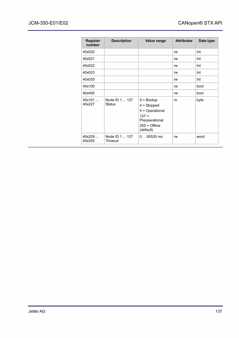
Jetter AG 137
JCM-350-E01/E02 CANopen® STX API
Register number
Description Value range Attributes Data type
40x020 rw Int
40x021 rw Int
40x022 rw Int
40x023 rw Int
40x030 rw Int
40x100 rw bool
40x400 rw bool
40x101 ... 40x227
Node ID 1 ... 127 Status
0 = Bootup 4 = Stopped 5 = Operational 127 = Preoperational 255 = Offline (default)
ro byte
40x229 ... 40x355
Node ID 1 ... 127 Timeout
0 ... 65535 ms rw word


Jetter AG 139
JCM-350-E01/E02 SAE J1939 STX API
7 SAE J1939 STX API
This chapter describes the STX functions of the SAE J1939 STX API.
SAE J1939 is an open standard for networking and communication in the commercial vehicle sector. The focal point of the application is the networking of the power train and chassis. The J1939 protocol originates from the international Society of Automotive Engineers (SAE) and works on the physical layer with CAN high-speed according to ISO 11898.
These STX functions are used in communication between the controller JCM-350-E01/E02 and other ECUs in the vehicle. As a rule, engine data, such as RPM, speed or coolant temperature are read and displayed.
The key SAE J1939 specifications are:
J1939-11 - Information on the physical layer J1939-21 - Information on the data link layer J1939-71 - Information on the application layer vehicles J1939-73 - Information on the application layer range analysis J1939-81 - Network management
Topic Page Content of a J1939 Message ...................................................................... 140 STX Function SAEJ1939Init ....................................................................... 142 STX Function SAEJ1939SetSA .................................................................. 144 STX Function SAEJ1939GetSA ................................................................. 145 STX Function SAEJ1939AddRx ................................................................. 146 STX Function SAEJ1939AddTx ................................................................. 149 STX Function SAEJ1939RequestPGN ...................................................... 152 STX Function SAEJ1939GetDM1 .............................................................. 155 STX Function SAEJ1939GetDM2 .............................................................. 158 STX Function SAEJ1939SetSPNConversion ............................................. 161 STX Function SAEJ1939GetSPNConversion ............................................ 163
Introduction
The SAE J1939 Standard
Application
Documentation
Contents

140 Jetter AG
7 SAE J1939 STX API
Content of a J1939 Message
The following diagram shows the content of a J1939 message:
Abbreviation Description
DA Destination Address
GE Group Extensions
PDU Protocol Data Unit
PGN Parameter Group Number
SA Source Address
The PGN is a number defined in the SAE J1939 standard that groups together several SPNs into a meaningful group. The PGN is part of the CAN identifier. The 8-byte data (PDU) contain the values of individual SPNs. The example below shows a PGN 65262 (0xFEEE): PGN 65262 Engine Temperature 1 - ET1
Part of the PGN Value Remarks
Transmission Repetition Rate 1 s
Data Length 8
Extended Data Page 0
Data Page 0
PDU Format 254
PDU Specific 238 PGN Supporting Information
Default Priority 6
Parameter Group Number 65262 in hex: 0xFEEE
Content of a J1939 Message
Meaning of the Parameter Group Number (PGN)

Jetter AG 141
JCM-350-E01/E02 SAE J1939 STX API
Start position Length Parameter name SPN
1 1 byte Engine Coolant Temperature 110
2 1 byte Engine Fuel Temperature 1 174
3 - 4 2 bytes Engine Oil Temperature 1 175
5 - 6 2 bytes Engine Turbocharger Oil Temperature 176
7 1 byte Engine Intercooler Temperature 52
8 1 byte Engine Intercooler Thermostat Opening 1134

142 Jetter AG
7 SAE J1939 STX API
STX Function SAEJ1939Init
Calling up the SAEJ1939Init () function initializes one of the CAN busses (not CAN 0 as this is reserved for CANopen®) for use with the J1939 protocol. From then on, the JCM-350-E01/E02 has got the SA (Source Address) assigned by the function parameter mySA. Thus, it has got its own device address on the bus.
Function SAEJ1939Init (
CANNo:Int,
mySA:Byte,
) :Int;
The function SAEJ1939Init () has the following parameters.
Parameter Description Value
CANNo CAN channel number 1 ... CANMAX
mySA Own source address 0 ... 253
This function transfers the following return values to the higher-level program.
Return value
0 OK
-1 Error when checking parameters
-3 Insufficient memory for SAE J1939
The value of the CANMAX parameter depends on the device. The following table provides information on this point.
Device CANMAX
BTM 07 2
BTM 012 1 - 2
BTM 011 n/a
JCM-350 4
JCM-620 2
JVM-104 n/a
JVM-407 2
JVM-407B 2
Initializing the CAN-Bus 1. The JCM-350-E01/E02 has got Node SA 20 (0x14). The JCM-350-E01/E02 can now send messages with the set SA (and only these messages).
Result := SAEJ1939Init(1, 20);
Introduction
Function declaration
Function parameters
Return value
Parameter CANNo
How to use this function

Jetter AG 143
JCM-350-E01/E02 SAE J1939 STX API
Address Claiming has not been implemented.
Address Claiming

144 Jetter AG
7 SAE J1939 STX API
STX Function SAEJ1939SetSA
The function SAEJ1939SetSA lets you change the own SA (Source Address) during runtime.
Function SAEJ1939SetSA (
CANNo:Int,
mySA:Byte,
) :Int;
The function SAEJ1939SetSA () includes the following parameters.
Parameter Description Value
CANNo CAN channel number 1 ... CANMAX
mySA New SA 0 ... 253
This function transfers the following return values to the higher-level program.
Return value
0 OK
-1 Error when checking parameters
The value of the CANMAX parameter depends on the device. The following table provides information on this point.
Device CANMAX
BTM 07 2
BTM 012 1 - 2
BTM 011 n/a
JCM-350 4
JCM-620 2
JVM-104 n/a
JVM-407 2
JVM-407B 2
Changing the SA during runtime. Result := SAEJ1939SetSA(1, 20);
Messages are immediately sent/received using the new SA.
Introduction
Function declaration
Function parameters
Return value
Parameter CANNo
How to use this function
Important note
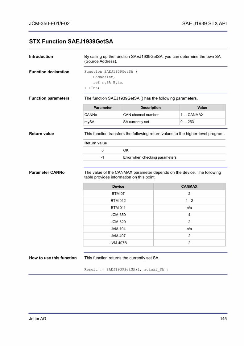
Jetter AG 145
JCM-350-E01/E02 SAE J1939 STX API
STX Function SAEJ1939GetSA
By calling up the function SAEJ1939GetSA, you can determine the own SA (Source Address).
Function SAEJ1939GetSA (
CANNo:Int,
ref mySA:Byte,
) :Int;
The function SAEJ1939GetSA () has the following parameters.
Parameter Description Value
CANNo CAN channel number 1 ... CANMAX
mySA SA currently set 0 ... 253
This function transfers the following return values to the higher-level program.
Return value
0 OK
-1 Error when checking parameters
The value of the CANMAX parameter depends on the device. The following table provides information on this point.
Device CANMAX
BTM 07 2
BTM 012 1 - 2
BTM 011 n/a
JCM-350 4
JCM-620 2
JVM-104 n/a
JVM-407 2
JVM-407B 2
This function returns the currently set SA. Result := SAEJ1939SetSA(1, actual_SA);
Introduction
Function declaration
Function parameters
Return value
Parameter CANNo
How to use this function
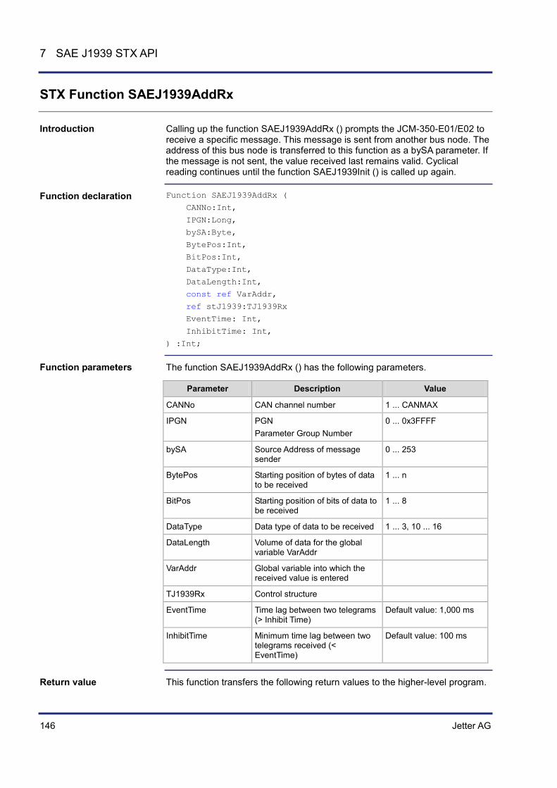
146 Jetter AG
7 SAE J1939 STX API
STX Function SAEJ1939AddRx
Calling up the function SAEJ1939AddRx () prompts the JCM-350-E01/E02 to receive a specific message. This message is sent from another bus node. The address of this bus node is transferred to this function as a bySA parameter. If the message is not sent, the value received last remains valid. Cyclical reading continues until the function SAEJ1939Init () is called up again.
Function SAEJ1939AddRx (
CANNo:Int,
IPGN:Long,
bySA:Byte,
BytePos:Int,
BitPos:Int,
DataType:Int,
DataLength:Int,
const ref VarAddr,
ref stJ1939:TJ1939Rx
EventTime: Int,
InhibitTime: Int,
) :Int;
The function SAEJ1939AddRx () has the following parameters.
Parameter Description Value
CANNo CAN channel number 1 ... CANMAX
IPGN PGN Parameter Group Number
0 ... 0x3FFFF
bySA Source Address of message sender
0 ... 253
BytePos Starting position of bytes of data to be received
1 ... n
BitPos Starting position of bits of data to be received
1 ... 8
DataType Data type of data to be received 1 ... 3, 10 ... 16
DataLength Volume of data for the global variable VarAddr
VarAddr Global variable into which the received value is entered
TJ1939Rx Control structure
EventTime Time lag between two telegrams (> Inhibit Time)
Default value: 1,000 ms
InhibitTime Minimum time lag between two telegrams received (< EventTime)
Default value: 100 ms
This function transfers the following return values to the higher-level program.
Introduction
Function declaration
Function parameters
Return value

Jetter AG 147
JCM-350-E01/E02 SAE J1939 STX API
Return value
0 OK
-1 Error when checking parameters
The value of the CANMAX parameter depends on the device. The following table provides information on this point.
Device CANMAX
BTM 07 2
BTM 012 1 - 2
BTM 011 n/a
JCM-350 4
JCM-620 2
JVM-104 n/a
JVM-407 2
JVM-407B 2
Data types include the following types:
Byte types Bit types SAEJ1939
1 - SAEJ1939_UNSIGNED8 SAEJ1939_BYTE
2 - SAEJ1939_UNSIGNED16 SAEJ1939_WORD
4 - SAEJ1939_UNSIGNED32 SAEJ1939_DWORD
n - SAEJ1939_STRING
- 1 SAEJ1939_1BIT
- 2 SAEJ1939_2BIT
- 3 SAEJ1939_3BIT
- 4 SAEJ1939_4BIT
- 5 SAEJ1939_5BIT
- 6 SAEJ1939_6BIT
- 7 SAEJ1939_7BIT
TJ1939Rx: Struct
// Status of received message byStatus : Byte;
// Priority of received message byPriority : Byte;
End_Struct;
Parameter CANNo
Parameter DataType
Control Structure TJ1939Rx

148 Jetter AG
7 SAE J1939 STX API
Result := SAEJ1939AddRx (
1,
0xFEEE,
0x00,
2
0
SAEJ1939_BYTE,
sizeof(var_Fueltemp),
var_Fueltemp,
struct_TJ1939Rx_EngineTemperatureTbl,
1500,
120);
The device JCM-350-E01/E02 with the own SA of 20 wants to receive and display the current fuel temperature. The parameters InhibitTime and EventTime are not explicitly specified when calling up the function. In this case, the default values are used. The controller acquiring the fuel temperature has got SA 0. In practice, the address of the controller can be found in the engine manufacturer's documentation. The fuel temperature has the SPN 174 and is a component (byte 2) of the PGN 65262 Engine Temperature 1.
#Include "SAEJ1939.stxp"
Var
bySAEJ1939Channel : Byte;
own_Source_Address : Byte;
// PGN 65262 Engine Temperature 1 Fueltemp : Byte;
EngineTemperatureTbl : TJ1939Rx;
End_Var;
Task main autorun
// Initializing CAN 1 bySAEJ1939Channel := 1;
own_Source_Address := 20;
SAEJ1939Init (bySAEJ1939Channel, own_Source_Address);
// Receiving fuel temperature SAEJ1939AddRx (bySAEJ1939Channel, 65262, 0x00, 2, 1, SAEJ1939_BYTE, sizeof(Fueltemp), Fueltemp, EngineTemperatureTbl);
End_Task;
For information on the data (priority, PGN, SA and data byte structure) refer to the manual provided by the engine manufacturer.
How to use this function
JetSym STX program
Engine manufacturer's manual

Jetter AG 149
JCM-350-E01/E02 SAE J1939 STX API
STX Function SAEJ1939AddTx
Calling up the function SAEJ1939AddTx () prompts the device JCM-350-E01/E02 to cyclically send a specific message via the bus. Cyclical sending continues until the function SAEJ1939Init () is called up again. Date are sent once the Event Time has elapsed or the given variables have changed and Inhibit Time has elapsed.
Function SAEJ1939AddTx (
CANNo:Int,
IPGN:Long,
BytePos:Int,
BitPos:Int,
dataType:Int,
DataLength:Int,
const ref VarAddr,
ref stJ1939:TJ1939Tx
EventTime: Int,
InhibitTime: Int,
) :Int;
The function SAEJ1939AddTx () has the following parameters.
Parameter Description Value
CANNo CAN channel number 1 ... CANMAX
IPGN PGN Parameter Group Number
0 ... 0x3FFFF
BytePos Starting position of the byte of data to be sent
1 ... n
BitPos Starting position of the bit of data to be sent
1 ... 8
dataType Data type of data to be sent 1 ... 3, 10 ... 16
DataLength Volume of data for the global variable VarAddr
VarAddr Global variable into which the value to be sent is entered
TJ1939Tx Control structure
EventTime Time lag between two telegrams (> Inhibit Time)
Default value: 1,000 ms
InhibitTime Minimum time lag between two telegrams received (< EventTime)
Default value: 100 ms
Introduction
Function declaration
Function parameters

150 Jetter AG
7 SAE J1939 STX API
This function transfers the following return values to the higher-level program.
Return value
0 OK
-1 Error when checking parameters
The value of the CANMAX parameter depends on the device. The following table provides information on this point.
Device CANMAX
BTM 07 2
BTM 012 1 - 2
BTM 011 n/a
JCM-350 4
JCM-620 2
JVM-104 n/a
JVM-407 2
JVM-407B 2
Data types include the following types:
Byte types Bit types SAEJ1939
1 - SAEJ1939_UNSIGNED8 SAEJ1939_BYTE
2 - SAEJ1939_UNSIGNED16 SAEJ1939_WORD
4 - SAEJ1939_UNSIGNED32 SAEJ1939_DWORD
n - SAEJ1939_STRING
- 1 SAEJ1939_1BIT
- 2 SAEJ1939_2BIT
- 3 SAEJ1939_3BIT
- 4 SAEJ1939_4BIT
- 5 SAEJ1939_5BIT
- 6 SAEJ1939_6BIT
- 7 SAEJ1939_7BIT
TJ1939Tx : Struct
// Status of sent message byStatus : Byte;
// Priority of sent message byPriority : Byte;
Return value
Parameter CANNo
Parameter DataType
Control Structure TJ1939Tx

Jetter AG 151
JCM-350-E01/E02 SAE J1939 STX API
End_Struct;
Result := SAEJ1939AddTx (
1,
0xFEEE,
0x00,
2
0
SAEJ1939_BYTE,
sizeof(var_Fueltemp),
var_Fueltemp,
struct_TJ1939Tx_EngineTemperatureTbl,
1500,
120);
Redefining the priority. Priority value 0 has the highest priority, priority value 7 has the lowest priority. A message with priority 6 can be superseded by a message with priority 4 (if the messages are sent at the same time). The parameters InhibitTime and EventTime are not explicitly specified when calling up the function. In this case, the default values are used. #Include "SAEJ1939.stxp"
Var
bySAEJ1939Channel : Byte;
own_Source_Address : Byte;
// PGN 65262 Engine Temperature 1 Fueltemp : Byte;
EngineTemperatureTbl : TJ1939Tx;
End_Var;
Task main autorun
// Initializing CAN 1 bySAEJ1939Channel := 1;
own_Source_Address := 20;
SAEJ1939Init (bySAEJ1939Channel, own_Source_Address);
// PGN 65262 Engine Temperature // Setting a new priority EngineTemperatureTbl.byPriority := 6;
SAEJ1939AddTx (bySAEJ1939Channel, 65262, 0x00, 2, 1, SAEJ1939_BYTE, sizeof(Fueltemp), Fueltemp, EngineTemperatureTbl);
End_Task;
For information on the data (priority, PGN, SA and data byte structure) refer to the manual provided by the engine manufacturer.
How to use this function
JetSym STX program
Engine manufacturer's manual

152 Jetter AG
7 SAE J1939 STX API
STX Function SAEJ1939RequestPGN
Calling up the function SAEJ1939RequestPGN () sends a request to the DA (Destination Address) following a PGN. This function is terminated only if a valid value has been received or the timeout of 1,250 ms has elapsed. To obtain the value of the requested message its receipt must be scheduled using the function SAEJ1939AddRx (). This function must constantly be recalled in cycles.
Function SAEJ1939RequestPGN (
CANNo:Int,
byDA:Byte,
ulPGN:Long,
byPriority:Byte,
) :Int;
The function SAEJ1939RequestPGN () has the following parameters.
Parameter Description Value
CANNo CAN channel number 1 ... CANMAX
byDA Destination Address Address from which the message is requested
0 ... 253 The own SA cannot be used
uIPGN PGN Parameter Group Number
0 ... 0x3FFFF
byPriority Priority 0 ... 7 Default value: 6
This function transfers the following return values to the higher-level program.
Return value
0 Message has been received
-1 Timeout, as no reply has been received
The value of the CANMAX parameter depends on the device. The following table provides information on this point.
Device CANMAX
BTM 07 2
BTM 012 1 - 2
BTM 011 n/a
JCM-350 4
JCM-620 2
JVM-104 n/a
Introduction
Function declaration
Function parameters
Return value
Parameter CANNo
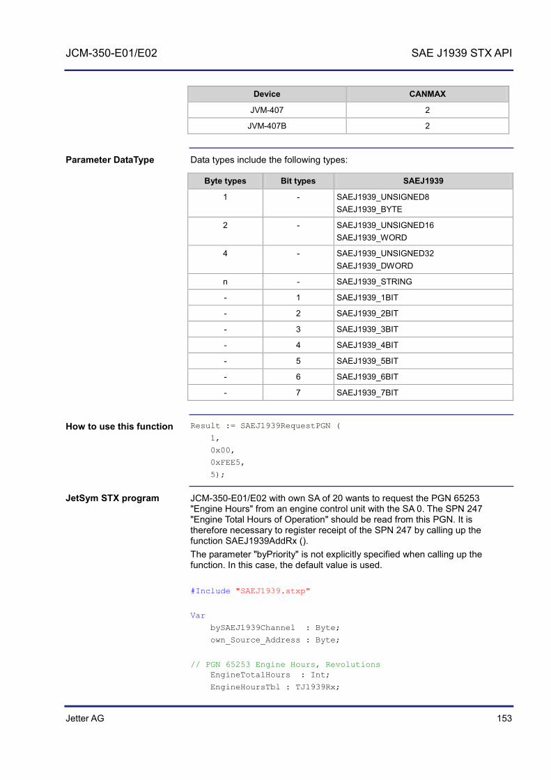
Jetter AG 153
JCM-350-E01/E02 SAE J1939 STX API
Device CANMAX
JVM-407 2
JVM-407B 2
Data types include the following types:
Byte types Bit types SAEJ1939
1 - SAEJ1939_UNSIGNED8 SAEJ1939_BYTE
2 - SAEJ1939_UNSIGNED16 SAEJ1939_WORD
4 - SAEJ1939_UNSIGNED32 SAEJ1939_DWORD
n - SAEJ1939_STRING
- 1 SAEJ1939_1BIT
- 2 SAEJ1939_2BIT
- 3 SAEJ1939_3BIT
- 4 SAEJ1939_4BIT
- 5 SAEJ1939_5BIT
- 6 SAEJ1939_6BIT
- 7 SAEJ1939_7BIT
Result := SAEJ1939RequestPGN (
1,
0x00,
0xFEE5,
5);
JCM-350-E01/E02 with own SA of 20 wants to request the PGN 65253 "Engine Hours" from an engine control unit with the SA 0. The SPN 247 "Engine Total Hours of Operation" should be read from this PGN. It is therefore necessary to register receipt of the SPN 247 by calling up the function SAEJ1939AddRx (). The parameter "byPriority" is not explicitly specified when calling up the function. In this case, the default value is used. #Include "SAEJ1939.stxp"
Var
bySAEJ1939Channel : Byte;
own_Source_Address : Byte;
// PGN 65253 Engine Hours, Revolutions EngineTotalHours : Int;
EngineHoursTbl : TJ1939Rx;
Parameter DataType
How to use this function
JetSym STX program

154 Jetter AG
7 SAE J1939 STX API
End_Var;
Task main autorun
// Initializing CAN 1 bySAEJ1939Channel := 1;
own_Source_Address := 20;
SAEJ1939Init (bySAEJ1939Channel, own_Source_Address);
// Engine Hours, Revolutions -- on Request SAEJ1939AddRx (bySAEJ1939Channel, 65253, 0x00, 1, 0, SAEJ1939_DWORD, sizeof(EngineTotalHours), EngineTotalHours, EngineHoursTbl, 5000, 150);
// Required for a cyclical task TaskAllEnableCycle ();
EnableEvents;
End_Task;
Task t_RequestPGN_5000 cycle 5000
Var
Return_value : Int;
End_Var;
// Requesting total machine operating hours Return_value := SAEJ1939RequestPGN (bySAEJ1939Channel, 0x00, 65253);
If Return_value Then
Trace ('PGN Request failed');
End_If;
End_Task;

Jetter AG 155
JCM-350-E01/E02 SAE J1939 STX API
STX Function SAEJ1939GetDM1
Calling up the function SAEJ1939GetDM1 () requests the current diagnostics error codes (also see SAE J1939-73 No. 5.7.1). The corresponding PGN number is 65226. This function must constantly be recalled in cycles.
Function SAEJ1939GetDM1 (
CANNo:Int,
bySA:Byte,
ref stJ1939DM1stat:TJ1939DM1STAT
ref stJ1939DM1msg:TJ1939DM1MSG
) :Int;
The function SAEJ1939GetDM1 () has the following parameters.
Parameter Description Value
CANNo CAN channel number 1 ... CANMAX
bySA Source Address of message sender
0 ... 253 The own SA cannot be used
stJ1939DM1stat lStatus lMsgCnt lBuffer
Lamp Status Number of received messages Size of variable stJ1939DM1msg
stJ1939DM1msg lSPN byOC byFMI
Error Code Error counter Error Type
This function transfers the following return values to the higher-level program.
Return value
0 OK
-1 Error when checking parameters
The value of the CANMAX parameter depends on the device. The following table provides information on this point.
Device CANMAX
BTM 07 2
BTM 012 1 - 2
BTM 011 n/a
JCM-350 4
JCM-620 2
JVM-104 n/a
Introduction
Function declaration
Function parameters
Return value
Parameter CANNo
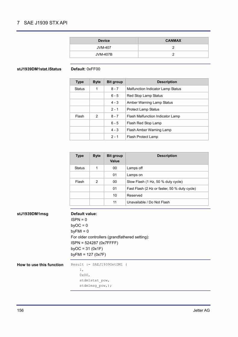
156 Jetter AG
7 SAE J1939 STX API
Device CANMAX
JVM-407 2
JVM-407B 2
Default: 0xFF00
Type Byte Bit group Description
Status 1 8 - 7 Malfunction Indicator Lamp Status
6 - 5 Red Stop Lamp Status
4 - 3 Amber Warning Lamp Status
2 - 1 Protect Lamp Status
Flash 2 8 - 7 Flash Malfunction Indicator Lamp
6 - 5 Flash Red Stop Lamp
4 - 3 Flash Amber Warning Lamp
2 - 1 Flash Protect Lamp
Type Byte Bit group Value
Description
Status 1 00 Lamps off
01 Lamps on
Flash 2 00 Slow Flash (1 Hz, 50 % duty cycle)
01 Fast Flash (2 Hz or faster, 50 % duty cycle)
10 Reserved
11 Unavailable / Do Not Flash
Default value: ISPN = 0 byOC = 0 byFMI = 0 For older controllers (grandfathered setting): ISPN = 524287 (0x7FFFF) byOC = 31 (0x1F) byFMI = 127 (0x7F)
Result := SAEJ1939GetDM1 (
1,
0x00,
stdm1stat_pow,
stdm1msg_pow,);
stJ1939DM1stat.lStatus
stJ1939DM1msg
How to use this function

Jetter AG 157
JCM-350-E01/E02 SAE J1939 STX API
By calling up the function SAEJ1939GetDM1 (), the JCM-350-E01/E02 requests the current diagnostics error code (PGN 65226). #Include "SAEJ1939.stxp"
Var
bySAEJ1939Channel : Byte;
own_Source_Address : Byte;
stdm1stat_pow : TJ1939DM1STAT;
stdm1msg_pow : Array[10] of STJ1939DM1MSG;
MyTimer : TTimer;
End_Var;
Task main autorun
// Initializing CAN 1 bySAEJ1939Channel := 1;
own_Source_Address := 20;
SAEJ1939Init (bySAEJ1939Channel, own_Source_Address);
TimerStart (MyTimer, T#2s);
Loop
When (TimerEnd (MyTimer)) Continue;
stdm1stat_pow.lBuffer := sizeof (stdm1msg_pow);
SAEJ1939GetDM1 (bySAEJ1939Channel, 0x00, stdm1stat_pow, stdm1msg_pow);
TimerStart (MyTimer, T#2s);
End_Loop;
End_Task;
JetSym STX program

158 Jetter AG
7 SAE J1939 STX API
STX Function SAEJ1939GetDM2
Calling up the function SAEJ1939GetDM2 () requests the diagnostics error codes that preceded the current ones (also see SAE J1939-73 No. 5.7.2). The corresponding PGN number is 65227.
Function SAEJ1939GetDM2 (
CANNo:Int,
bySA:Byte,
ref stJ1939DM2stat:TJ1939DM2STAT
ref stJ1939DM2msg:TJ1939DM2MSG
) :Int;
The function SAEJ1939GetDM2 () has the following parameters.
Parameter Description Value
CANNo CAN channel number 1 ... CANMAX
bySA Source Address of message sender
0 ... 253 The own SA cannot be used
stJ1939DM2stat lStatus lMsgCnt lBuffer
Lamp status Number of received messages Size of variable stJ1939DM2msg
stJ1939DM2msg lSPN byOC byFMI
Error Code Error counter Error Type
This function transfers the following return values to the higher-level program.
Return value
0 OK
-1 Error when checking parameters
The value of the CANMAX parameter depends on the device. The following table provides information on this point.
Device CANMAX
BTM 07 2
BTM 012 1 - 2
BTM 011 n/a
JCM-350 4
JCM-620 2
JVM-104 n/a
Introduction
Function declaration
Function parameters
Return value
Parameter CANNo
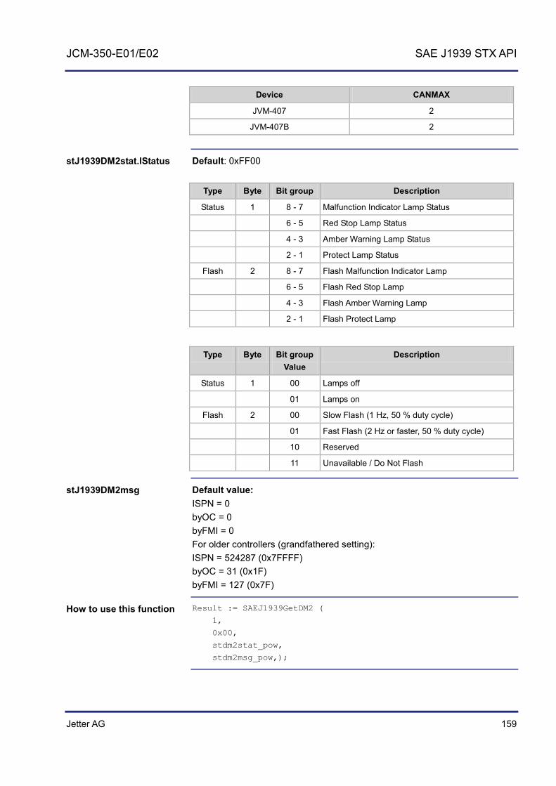
Jetter AG 159
JCM-350-E01/E02 SAE J1939 STX API
Device CANMAX
JVM-407 2
JVM-407B 2
Default: 0xFF00
Type Byte Bit group Description
Status 1 8 - 7 Malfunction Indicator Lamp Status
6 - 5 Red Stop Lamp Status
4 - 3 Amber Warning Lamp Status
2 - 1 Protect Lamp Status
Flash 2 8 - 7 Flash Malfunction Indicator Lamp
6 - 5 Flash Red Stop Lamp
4 - 3 Flash Amber Warning Lamp
2 - 1 Flash Protect Lamp
Type Byte Bit group Value
Description
Status 1 00 Lamps off
01 Lamps on
Flash 2 00 Slow Flash (1 Hz, 50 % duty cycle)
01 Fast Flash (2 Hz or faster, 50 % duty cycle)
10 Reserved
11 Unavailable / Do Not Flash
Default value: ISPN = 0 byOC = 0 byFMI = 0 For older controllers (grandfathered setting): ISPN = 524287 (0x7FFFF) byOC = 31 (0x1F) byFMI = 127 (0x7F)
Result := SAEJ1939GetDM2 (
1,
0x00,
stdm2stat_pow,
stdm2msg_pow,);
stJ1939DM2stat.lStatus
stJ1939DM2msg
How to use this function

160 Jetter AG
7 SAE J1939 STX API
By calling up the function SAEJ1939GetDM2 (), the JCM-350-E01/E02 requests the current diagnostics error codes (PGN 65227). #Include "SAEJ1939.stxp"
Var
bySAEJ1939Channel : Byte;
own_Source_Address : Byte;
stdm2stat_pow : TJ1939DM2STAT;
stdm2msg_pow : Array[10] of STJ1939DM2MSG;
End_Var;
// Initializing CAN 1 bySAEJ1939Channel := 1;
own_Source_Address := 20;
SAEJ1939Init (bySAEJ1939Channel, own_Source_Address);
// Required for a cyclical task TaskAllEnableCycle ();
EnableEvents;
End_Task;
Task t_RequestPGN_5000 cycle 5000
Var
Return_value : Int;
End_Var;
// Requesting diagnostics error codes DM2 POW stdm2stat_pow.lBuffer := sizeof (stdm2msg_pow);
Return_value := SAEJ1939GetDM2 (bySAEJ1939Channel, 0x00, stdm2stat_pow, stdm2msg_pow);
If Return_value Then
Trace ('DM2 Request failed');
End_If;
End_Task;
JetSym STX program
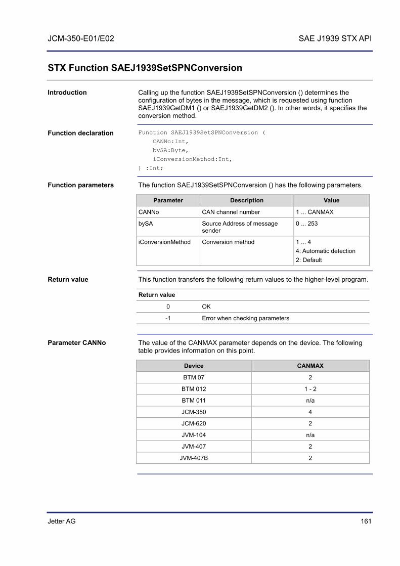
Jetter AG 161
JCM-350-E01/E02 SAE J1939 STX API
STX Function SAEJ1939SetSPNConversion
Calling up the function SAEJ1939SetSPNConversion () determines the configuration of bytes in the message, which is requested using function SAEJ1939GetDM1 () or SAEJ1939GetDM2 (). In other words, it specifies the conversion method.
Function SAEJ1939SetSPNConversion (
CANNo:Int,
bySA:Byte,
iConversionMethod:Int,
) :Int;
The function SAEJ1939SetSPNConversion () has the following parameters.
Parameter Description Value
CANNo CAN channel number 1 ... CANMAX
bySA Source Address of message sender
0 ... 253
iConversionMethod Conversion method 1 ... 4 4: Automatic detection 2: Default
This function transfers the following return values to the higher-level program.
Return value
0 OK
-1 Error when checking parameters
The value of the CANMAX parameter depends on the device. The following table provides information on this point.
Device CANMAX
BTM 07 2
BTM 012 1 - 2
BTM 011 n/a
JCM-350 4
JCM-620 2
JVM-104 n/a
JVM-407 2
JVM-407B 2
Introduction
Function declaration
Function parameters
Return value
Parameter CANNo

162 Jetter AG
7 SAE J1939 STX API
Result := SAEJ1939SetSPNConversion (
1,
0xAE,
4);
How to use this function

Jetter AG 163
JCM-350-E01/E02 SAE J1939 STX API
STX Function SAEJ1939GetSPNConversion
Calling up the function SAEJ1939GetSPNConversion () ascertains the current conversion method set.
Function SAEJ1939SetSPNConversion (
CANNo:Int,
bySA:Byte,
iConversionMethod:Int,
) :Int;
The function SAEJ1939GetSPNConversion () has the following parameters.
Parameter Description Value
CANNo CAN channel number 1 ... CANMAX
bySA Source Address of message sender
0 ... 253
iConversionMethod Conversion method 1 ... 4 4: Automatic detection 2: Default
This function transfers the following return values to the higher-level program.
Return value
0 OK
-1 Error when checking parameters
The value of the CANMAX parameter depends on the device. The following table provides information on this point.
Device CANMAX
BTM 07 2
BTM 012 1 - 2
BTM 011 n/a
JCM-350 4
JCM-620 2
JVM-104 n/a
JVM-407 2
JVM-407B 2
Introduction
Function declaration
Function parameters
Return value
Parameter CANNo

164 Jetter AG
7 SAE J1939 STX API
Result := SAEJ1939GetSPNConversion (
1,
0xAE,
actual_conversion_method);
How to use this function

Jetter AG 165
JCM-350-E01/E02 Programming the JCM-350-E01/E02
8 Programming the JCM-350-E01/E02
This chapter supports you in programming a JCM-350-E01/E02 to be installed in a vehicle. It covers the following topics:
Programming the JCM-350-E01/E02 Examples of how to use individual registers of a JCM-350-E01/E02
To avoid repetitions and to simplify representation we use the following placeholders:
Placeholder Usage Description
x Several similar registers or similar I/Os
Simplifies description. Digital outputs, for example, have the same properties when used with different registers and outputs.
y If the JCM-350-E02 is equipped with two I/O modules to distinguish between:
I/O module 1 I/O module 2
Here "y" stands for value "1" or "2". Value "1" relates to connectors X110, X118, X119. Value "2" relates to connectors X210, X218, X219. Note: In the case of JCM-350-E01 "y" is always 1.
The following example refers to the value of digital input 7: Register number 600y001xx represents the register of the digital input.
If you wish to address digital input 7 on connector X218, replace the placeholder as follows:
Replace "y" by "2" and "xx" by "07"
The resulting register number R 600200107 refers to the following:
"2" stands for model JCM-350-E02 "07" stands for digital input 7 at pin 30 of connector X218
If you wish to address digital input 7 on connector X118, replace the placeholder as follows:
Replace "y" by "1" and "xx" by "07"
The resulting register number R 600100107 refers to the following:
"1" stands for model JCM-350-E01 "07" stands for digital input 7 at pin 30 of connector X118
To be able to program the JCM-350-E01/E02, the following prerequisites must be fulfilled:
A USB CAN adaptor between PC and JCM-350-E01/E02 and the driver software for this adaptor have been installed.
Purpose of this chapter
Use of placeholders
Example of how to use placeholders
Prerequisites

166 Jetter AG
8 Programming the JCM-350-E01/E02
The device is now connected to a PC via CAN bus. The programming tool JetSym 4.3 or higher is installed on the PC.
Topic Page Abbreviations, module register properties and formats .............................. 167 Programming the device ............................................................................. 168 Programming the operator panel ................................................................ 176 Programming digital inputs and outputs ...................................................... 186 Programming analog inputs and outputs .................................................... 222
Table of contents

Jetter AG 167
JCM-350-E01/E02 Programming the JCM-350-E01/E02
Abbreviations, module register properties and formats
The abbreviations used in this document are listed in the following table:
Abbreviation Description
R 100 Register 100
MR 150 Module register 150
Each module register is characterized by certain properties. For many module registers most properties are identical. For example, their value after reset is zero. In the following description, module register properties are mentioned only if a property deviates from the following default properties.
Module register properties Default property for most module registers
Type of access Read/write
Value after reset 0 or undefined (e.g. the release number)
Takes effect Immediately
Write access Always
Data type Integer
The number formats used in this document are listed in the following table:
Notation Numerical format
100 Decimal
0x100 Hexadecimal
0b100 Binary
The notation for sample programs used in this document is listed in the following table:
Notation Description Var, When, Task Keyword BitClear(); Commands 100 0x100 0b100 Constant numerical values
// This is a comment Comment
// ... Further program processing
Abbreviations
Module register properties
Number formats
JetSym sample programs

168 Jetter AG
8 Programming the JCM-350-E01/E02
8.1 Programming the device
This chapter describes how to program cross-module registers and the state of I/O modules 1 and 2. These registers let you enable communication and enable or disable, for example, analog or digital peripherals.
Topic Page Overview of Registers: JCM-350-E01/E02 - Status and instructions ......... 169
Introduction
Table of contents

Jetter AG 169
JCM-350-E01/E02 Programming the JCM-350-E01/E02
Overview of Registers: JCM-350-E01/E02 - Status and instructions
Launching the STX program
The value of this register defines the operating mode of the controller.
Register properties
Values 0 STOP
1 RUN
2 LOAD
Type of access Read access: Present value
Write access: New value; becomes effective after restart
Communication status
Register R 600000400 indicates in bit-coded format the status of communication enabling:
Register properties
Values 00 Communication is not enabled.
01 Communication for I/O module 1 is enabled.
10 Communication for I/O module 2 is enabled.
Communication is enabled
Communication enabling applies to the following:
Digital I/Os Relay Frequency inputs To enable communication, enter the following values into register R 600000401: Value "11" for I/O module 1, or value "12" for I/O module 2.
Commands
11 Communication for I/O module 1 is enabled.
12 Communication for I/O module 2 is enabled.
Status register of I/O module 1/2
This register indicates the status of the I/O module in bit-coded format.
R 600000020
R 600000400
R 600000401
R 600y44000
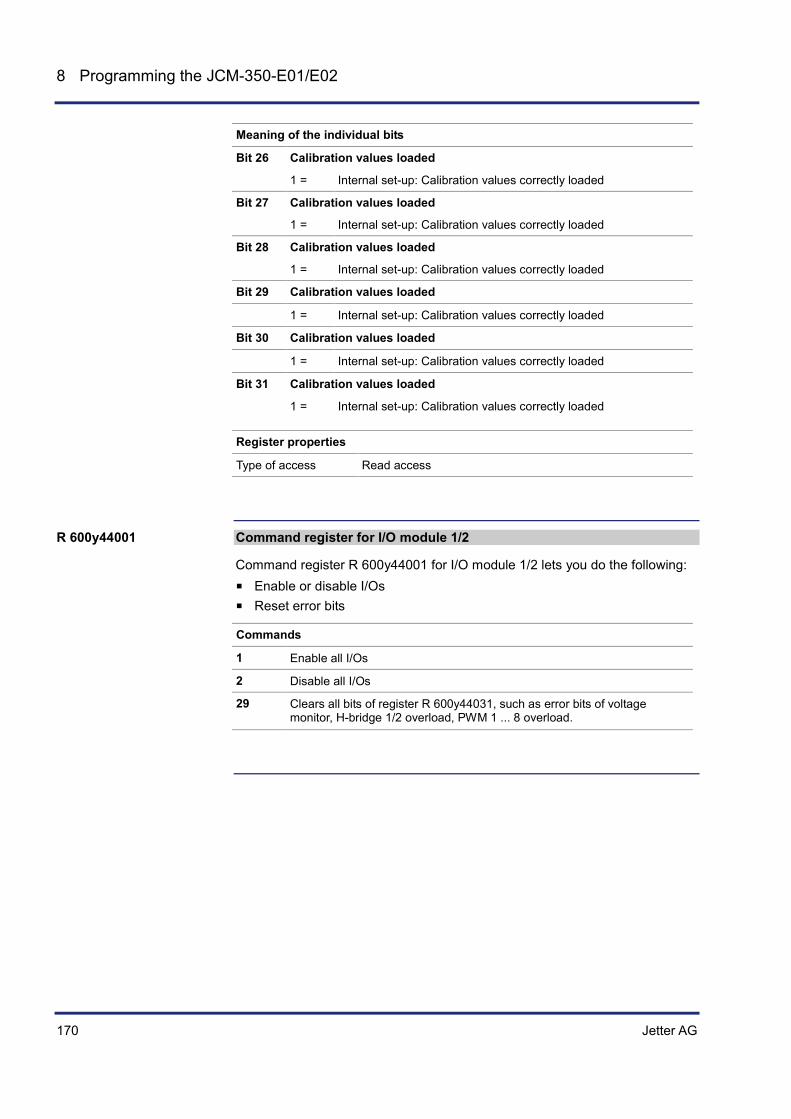
170 Jetter AG
8 Programming the JCM-350-E01/E02
Meaning of the individual bits
Bit 26 Calibration values loaded
1 = Internal set-up: Calibration values correctly loaded
Bit 27 Calibration values loaded
1 = Internal set-up: Calibration values correctly loaded
Bit 28 Calibration values loaded
1 = Internal set-up: Calibration values correctly loaded
Bit 29 Calibration values loaded
1 = Internal set-up: Calibration values correctly loaded
Bit 30 Calibration values loaded
1 = Internal set-up: Calibration values correctly loaded
Bit 31 Calibration values loaded
1 = Internal set-up: Calibration values correctly loaded
Register properties
Type of access Read access
Command register for I/O module 1/2
Command register R 600y44001 for I/O module 1/2 lets you do the following:
Enable or disable I/Os Reset error bits
Commands
1 Enable all I/Os
2 Disable all I/Os
29 Clears all bits of register R 600y44031, such as error bits of voltage monitor, H-bridge 1/2 overload, PWM 1 ... 8 overload.
R 600y44001
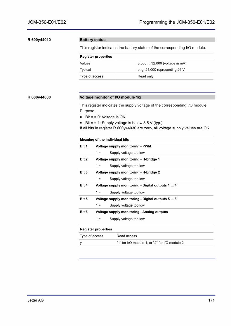
Jetter AG 171
JCM-350-E01/E02 Programming the JCM-350-E01/E02
Battery status
This register indicates the battery status of the corresponding I/O module.
Register properties
Values 8,000 ... 32,000 (voltage in mV)
Typical e. g. 24,000 representing 24 V
Type of access Read only
Voltage monitor of I/O module 1/2
This register indicates the supply voltage of the corresponding I/O module. Purpose:
Bit n = 0: Voltage is OK Bit n = 1: Supply voltage is below 8.5 V (typ.) If all bits in register R 600y44030 are zero, all voltage supply values are OK.
Meaning of the individual bits
Bit 1 Voltage supply monitoring - PWM
1 = Supply voltage too low
Bit 2 Voltage supply monitoring - H-bridge 1
1 = Supply voltage too low
Bit 3 Voltage supply monitoring - H-bridge 2
1 = Supply voltage too low
Bit 4 Voltage supply monitoring - Digital outputs 1 ... 4
1 = Supply voltage too low
Bit 5 Voltage supply monitoring - Digital outputs 5 ... 8
1 = Supply voltage too low
Bit 6 Voltage supply monitoring - Analog outputs
1 = Supply voltage too low
Register properties
Type of access Read access
y "1" for I/O module 1, or "2" for I/O module 2
R 600y44010
R 600y44030

172 Jetter AG
8 Programming the JCM-350-E01/E02
Voltage monitor with latch function - I/O module 1/2
This register indicates the supply voltage of the corresponding I/O module. Purpose:
Bit n = 0: Voltage is OK Bit n = 1: Supply voltage is below 8.5 V (typ.) If all bits in register R 600y44031 are zero, all voltage supply values are OK. The function of this register is identical with that of register R 600y44030. The only difference is that you must clear individual bits yourself (e. g. in the application program).
Meaning of the individual bits
Bit 1 Voltage supply monitoring - PWM
1 = Supply voltage too low
Bit 2 Voltage supply monitoring - H-bridge 1
1 = Supply voltage too low
Bit 3 Voltage supply monitoring - H-bridge 2
1 = Supply voltage too low
Bit 4 Voltage supply monitoring - Digital outputs 1 ... 4
1 = Supply voltage too low
Bit 5 Voltage supply monitoring - Digital outputs 5 ... 8
1 = Supply voltage too low
Bit 6 Voltage supply monitoring - Analog outputs
1 = Supply voltage too low
Register properties
Read access Actual value
Write access Clearing value
R 600y44031

Jetter AG 173
JCM-350-E01/E02 Programming the JCM-350-E01/E02
Timeout counter - Data protocol
This register is a timeout counter for the internal data protocol. When the event "Busy Timeout" occurs, the error counter is incremented by one. This register allows read/write access.
Register properties
Name Error Busy Timeout Counter
Value range 32 bits
Read access Actual value
Write access New value
FrameCheckSequence_Wrong Counter
This register is a counter for the internal data protocol. When the event "FrameCheckSequence" occurs, the error counter is incremented by one. This register allows read/write access.
Register properties
Name FrameCheckSequence_Wrong Counter
Value range 32 bits
Read access Actual value
Write access New value
IP address
This register lets you set the IP address. This register allows read/write access. This register is remanent.
Register properties
Name IP address
Value range 32 bits
Read access Actual value
Write access New value
R 600000010
R 600000011
R 104531

174 Jetter AG
8 Programming the JCM-350-E01/E02
IP mask
This register lets you set the IP mask. This register allows read/write access. This register is remanent.
Register properties
Name IP mask
Value range 32 bits
Read access Actual value
Write access New value
IP gateway
This register lets you set the IP gateway. This register allows read/write access. This register is remanent.
Register properties
Name IP gateway
Value range 32 bits
Read access Actual value
Write access New value
Unscaled temperature measurement in [°C] at location 1/2/3 of I/O module 1/2
The device measures its PCB temperature at three locations. Register R 600y21x102 indicates the unscaled value ranging 0 ... 4.095 (where x = 1 ... 3).
Register properties
Name Temperature 1 / 2 / 3
Value range 0 ... 4,095
Read access Allowed
Write access Disabled
R 104532
R 104533
R 600y21x02
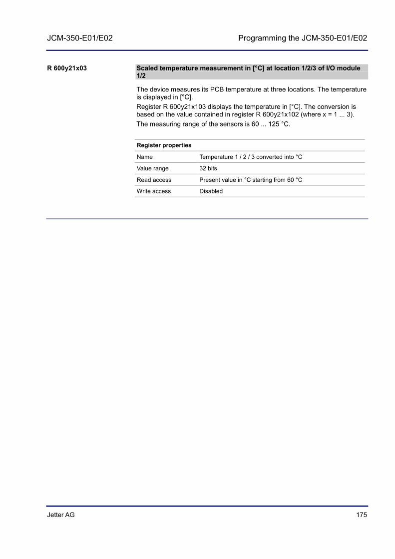
Jetter AG 175
JCM-350-E01/E02 Programming the JCM-350-E01/E02
Scaled temperature measurement in [°C] at location 1/2/3 of I/O module 1/2
The device measures its PCB temperature at three locations. The temperature is displayed in [°C]. Register R 600y21x103 displays the temperature in [°C]. The conversion is based on the value contained in register R 600y21x102 (where x = 1 ... 3). The measuring range of the sensors is 60 ... 125 °C.
Register properties
Name Temperature 1 / 2 / 3 converted into °C
Value range 32 bits
Read access Present value in °C starting from 60 °C
Write access Disabled
R 600y21x03

176 Jetter AG
8 Programming the JCM-350-E01/E02
8.2 Programming the operator panel
This chapter describes how to program the operator panel. The JCM-350-E01/E02 is available with two different operator panels. These two models differ in their appearance and in the way they are programmed:
Operator panel mode 1 has dual-color LEDs Operator panel mode 2 has single-color LEDs
Topic Page Operator panel: Programming, variant 1 .................................................... 177 Description of Registers: Operator panel, variant 1 .................................... 178 Operator panel: Programming, variant 2 .................................................... 182 Description of Registers: Operator panel, variant 2 .................................... 183
Introduction
Table of contents

Jetter AG 177
JCM-350-E01/E02 Programming the JCM-350-E01/E02
Operator panel: Programming, variant 1
Jetter AG do no longer ship this model of the operator panel. The illustration below shows a JCM-350-E01/E02:
The illustration below shows how the operator panel is arranged:
F1
F2
F3
F4
F5
F6
F7
F8
MODE
CAN 5
FAILURE
SUPPLY
NODE
CAN 4
CAN 3
CAN 2
CAN 1
RUN TEACHCONFIG
1
2
Number Description
1 Dual-color mode LED (green/red)
2 Keys F1 through F8
The operator panel uses the third color to indicate a further mode (e. g. CONFIG). If you mix the two colors by activating green and red at the same time, you get a third color, i. e. amber.
Operator panel
Operator panel, variant 1

178 Jetter AG
8 Programming the JCM-350-E01/E02
Description of Registers: Operator panel, variant 1
Keyboard
Register "Keyboard" indicates the key state of the operator panel in bit-coded format. This register is write-protected, not remanent and contains the current state of the keyboard.
Meaning of the individual bits
Bit 0 State of key "F1"
1 = Key F1 pressed
Bit 1 State of key "F2"
1 = Key F2 pressed
Bit 2 State of key "F3"
1 = Key F3 pressed
Bit 3 State of key "F4"
1 = Key F4 pressed
Bit 4 State of key "F5"
1 = Key F5 pressed
Bit 5 State of key "F6"
1 = Key F6 pressed
Bit 6 State of key "F7"
1 = Key F7 pressed
Bit 7 State of key "F8"
1 = Key F8 pressed
Bit 8 State of key "MODE"
1 = Key MODE pressed
Register properties
Type of access Read only
R 600000312

Jetter AG 179
JCM-350-E01/E02 Programming the JCM-350-E01/E02
LED_green
Register "LED_green" indicates the state of the green LEDs on the operator panel. This register allows read/write access.
Meaning of the individual bits
Bit 0 Status of green LED "NODE"
1 = Green LED "NODE" is lit
Bit 1 Status of green LED "SUPPLY"
1 = Green LED "SUPPLY" is lit
Bit 2 Status of green LED "FAILURE"
1 = Green LED "FAILURE" is lit
Bit 3 Status of green LED "CAN 5"
1 = Green LED "CAN 5" is lit
Bit 4 Status of green LED "CAN 4"
1 = Green LED "CAN 4" is lit
Bit 5 Status of green LED "CAN 3"
1 = Green LED "CAN 3" is lit
Bit 6 Status of green LED "CAN 2"
1 = Green LED "CAN 2" is lit
Bit 7 Status of green LED "CAN 1"
1 = Green LED "CAN 1" is lit
Register properties
Read access Actual value
Write access New value
R 600000320

180 Jetter AG
8 Programming the JCM-350-E01/E02
LED_red
Register "LED_red" indicates the state of the red LEDs on the operator panel. This register allows read/write access.
Meaning of the individual bits
Bit 0 Status of red LED "NODE"
1 = Red LED "NODE" is lit
Bit 1 Status of red LED "SUPPLY"
1 = Red LED "SUPPLY" is lit
Bit 2 Status of red LED "FAILURE"
1 = Red LED "FAILURE" is lit
Bit 3 Status of red LED "CAN 5"
1 = Red LED "CAN 5" is lit
Bit 4 Status of red LED "CAN 4"
1 = Red LED "CAN 4" is lit
Bit 5 Status of red LED "CAN 3"
1 = Red LED "CAN 3" is lit
Bit 6 Status of red LED "CAN 2"
1 = Red LED "CAN 2" is lit
Bit 7 Status of red LED "CAN 1"
1 = Red LED "CAN 1" is lit
Register properties
Read access Actual value
Write access New value
R 600000321
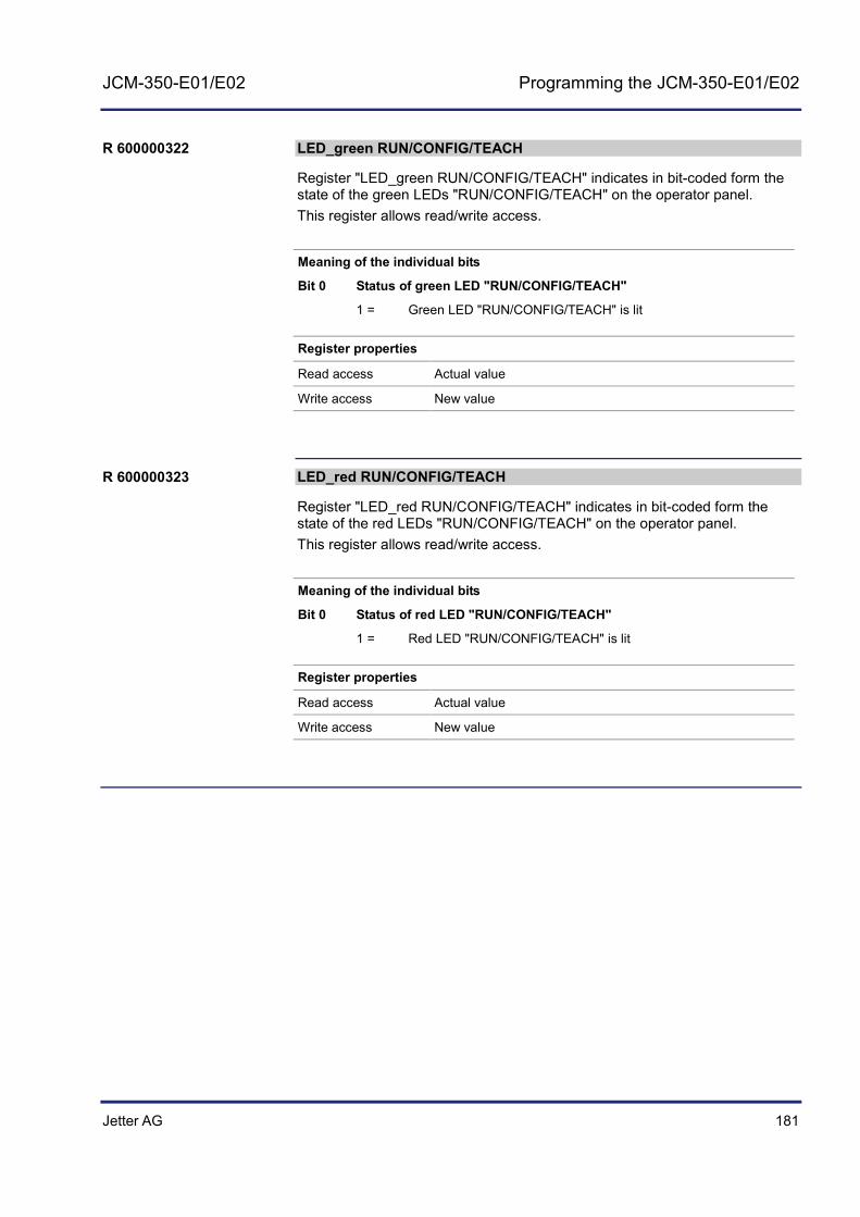
Jetter AG 181
JCM-350-E01/E02 Programming the JCM-350-E01/E02
LED_green RUN/CONFIG/TEACH
Register "LED_green RUN/CONFIG/TEACH" indicates in bit-coded form the state of the green LEDs "RUN/CONFIG/TEACH" on the operator panel. This register allows read/write access.
Meaning of the individual bits
Bit 0 Status of green LED "RUN/CONFIG/TEACH"
1 = Green LED "RUN/CONFIG/TEACH" is lit
Register properties
Read access Actual value
Write access New value
LED_red RUN/CONFIG/TEACH
Register "LED_red RUN/CONFIG/TEACH" indicates in bit-coded form the state of the red LEDs "RUN/CONFIG/TEACH" on the operator panel. This register allows read/write access.
Meaning of the individual bits
Bit 0 Status of red LED "RUN/CONFIG/TEACH"
1 = Red LED "RUN/CONFIG/TEACH" is lit
Register properties
Read access Actual value
Write access New value
R 600000322
R 600000323

182 Jetter AG
8 Programming the JCM-350-E01/E02
Operator panel: Programming, variant 2
The illustration below shows a JCM-350-E01/E02:
The illustration below shows how the operator panel is arranged:
F1
F2
F3
F4
F5
F6
F7
F8
MODE
FAILURE
SUPPLY
NODE
CAN 3
CAN 2
CAN 1
CAN 5 /
CAN 4 /
RUN TEACHCONFIG
1
2
Number Description
1 Single-color mode LEDs (green or red)
2 Keys F1 through F8
Operator panel
Operator panel, variant 2

Jetter AG 183
JCM-350-E01/E02 Programming the JCM-350-E01/E02
Description of Registers: Operator panel, variant 2
Keyboard
Register "Keyboard" indicates the key state of the operator panel in bit-coded format. This register is write-protected, not remanent and contains the current state of the operator panel.
Meaning of the individual bits
Bit 0 State of key "F1"
1 = Key F1 pressed
Bit 1 State of key "F2"
1 = Key F2 pressed
Bit 2 State of key "F3"
1 = Key F3 pressed
Bit 3 State of key "F4"
1 = Key F4 pressed
Bit 4 State of key "F5"
1 = Key F5 pressed
Bit 5 State of key "F6"
1 = Key F6 pressed
Bit 6 State of key "F7"
1 = Key F7 pressed
Bit 7 State of key "F8"
1 = Key F8 pressed
Bit 8 State of key "MODE"
1 = Key MODE pressed
Register properties
Type of access Read only
R 600000312
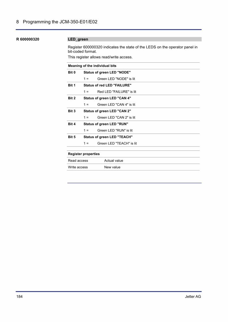
184 Jetter AG
8 Programming the JCM-350-E01/E02
LED_green
Register 600000320 indicates the state of the LEDS on the operator panel in bit-coded format. This register allows read/write access.
Meaning of the individual bits
Bit 0 Status of green LED "NODE"
1 = Green LED "NODE" is lit
Bit 1 Status of red LED "FAILURE"
1 = Red LED "FAILURE" is lit
Bit 2 Status of green LED "CAN 4"
1 = Green LED "CAN 4" is lit
Bit 3 Status of green LED "CAN 2"
1 = Green LED "CAN 2" is lit
Bit 4 Status of green LED "RUN"
1 = Green LED "RUN" is lit
Bit 5 Status of green LED "TEACH"
1 = Green LED "TEACH" is lit
Register properties
Read access Actual value
Write access New value
R 600000320

Jetter AG 185
JCM-350-E01/E02 Programming the JCM-350-E01/E02
LED_red
Register 600000321 indicates the state of the LEDS on the operator panel in bit-coded format. This register allows read/write access.
Meaning of the individual bits
Bit 0 Status of red LED "SUPPLY"
1 = Red LED "SUPPLY" is lit
Bit 1 Status of green LED "CAN 5"
1 = Green LED "CAN 5" is lit
Bit 2 Status of green LED "CAN 3"
1 = Green LED "CAN 3" is lit
Bit 3 Status of green LED "CAN 1"
1 = Green LED "CAN 1" is lit
Bit 4 Status of green LED "CONFIG"
1 = Green LED "CONFIG" is lit
Register properties
Read access Actual value
Write access New value
R 600000321
186 Jetter AG
8 Programming the JCM-350-E01/E02
8.3 Programming digital inputs and outputs
This chapter describes how digital input and output signals are processed.
Each digital input and output can be configured and operated regardless of the configuration of the other digital inputs and outputs.
Topic Page Digital output 1 ... 8 ..................................................................................... 187 Digital input 1 ... 11...................................................................................... 194 Digital input 12 ... 15 (frequency input) ....................................................... 201 Frequency measurement ............................................................................ 204 PWM outputs 1 ... 8 .................................................................................... 210 Relay outputs 1 ... 4 .................................................................................... 214 H-bridges 1 ... 2 .......................................................................................... 216
Introduction
Independence of digital inputs and outputs
Table of contents
Jetter AG 187
JCM-350-E01/E02 Programming the JCM-350-E01/E02
8.3.1 Digital output 1 ... 8
This chapter describes how digital outputs are used.
Monitoring of outputs Bit-coded access to digital outputs 1 ... 8 Special functions:
• Bit-coded access to analog outputs as digital outputs • Bit-coded access to PWM outputs as digital outputs
The table below shows how placeholders are used to address individual digital outputs. Throughout this chapter the following rules apply:
Placeholder Value Purpose
y 1 ... 2 I/O module 1 ... 2
x 1 ... 8 Digital output 1 ... 8
Topic Page Registers for monitoring digital values ........................................................ 188 Registers for digital value output ................................................................ 192
Introduction
Addressing by means of placeholders
Table of contents

188 Jetter AG
8 Programming the JCM-350-E01/E02
Registers for monitoring digital values
Status of digital outputs 1 ... 8
This register contains the value of the individual digital output.
Meaning of the individual bits
Bit 0 Collective message "I2t overload"
1 = At least one output has an I2t overload
Bit 1 Status of digital output 1
1 = Output is short-circuited
Bit 2 Status of digital output 2
1 = Output is short-circuited
Bit 3 Status of digital output 3
1 = Output is short-circuited
Bit 4 Status of digital output 4
1 = Output is short-circuited
Bit 5 Status of digital output 5
1 = Output is short-circuited
Bit 6 Status of digital output 6
1 = Output is short-circuited
Bit 7 Status of digital output 7
1 = Output is short-circuited
Bit 8 Status of digital output 8
1 = Output is short-circuited
Register properties
Name Status of digital outputs
Type of access Read only
R 600y00000

Jetter AG 189
JCM-350-E01/E02 Programming the JCM-350-E01/E02
Status of I2t monitoring of digital outputs 1 ... 8
This register contains the value of I2t monitoring of digital outputs. Command 22 lets you clear the state "Overload". Bit 9 and bit 10 are I2t collective bits for digital outputs 1 ... 4 and 5 ... 8.
Meaning of the individual bits
Bit 1 Status of digital output 1
1 = Output is overloaded
Bit 2 Status of digital output 2
1 = Output is overloaded
Bit 3 Status of digital output 3
1 = Output is overloaded
Bit 4 Status of digital output 4
1 = Output is overloaded
Bit 5 Status of digital output 5
1 = Output is overloaded
Bit 6 Status of digital output 6
1 = Output is overloaded
Bit 7 Status of digital output 7
1 = Output is overloaded
Bit 8 Status of digital output 8
1 = Output is overloaded
Bit 9 Status of overcurrent monitoring, collective bit for 1 ... 4
1 = I2t overcurrent (total current) trip for digital outputs 1 ... 4
Bit 10 Status of overcurrent monitoring, collective bit for 5 ... 8
1 = I2t overcurrent (total current) trip for digital outputs 5 ... 8
Register properties
Name Status of I2t monitoring for each output
Type of access Read access
R600y01000

190 Jetter AG
8 Programming the JCM-350-E01/E02
Status of I2t monitoring of digital outputs 1 ... 8
This register indicates the status of I2t monitoring of the digital outputs.
Register properties
Values 0 Digital output x - No overload
1 I2t monitoring signals overload
Value of I2t monitoring of individual digital outputs
This register contains a value indicating the heating of each digital output.
Register properties
Values 0% ... Digital output x - No overload
100% I2t monitoring signals overload
Value of I2t monitoring of digital outputs 1 ... 4
This register indicates the status of overcurrent protection for outputs 1 ... 4.
Register properties
Values 0% ... Digital outputs 1 ... 4 - No overload.
100% I2t monitoring signals overload
Value of I2t monitoring of individual digital outputs
This register indicates the status of overcurrent protection for outputs 5 ... 8.
Register properties
Values 0% ... Digital outputs 5 ... 8 - No overload.
100% I2t monitoring signals overload
R 600y01001x
R 600y0010x
R 600y00109
R 600y00110

Jetter AG 191
JCM-350-E01/E02 Programming the JCM-350-E01/E02
Current of digital output 1 ... 8
The value in this register is output in mA, where a value of 1,230 corresponds to an amperage of 1.23 A.
Register properties
Value In mA 0 ... 40,000
R 600y22x03
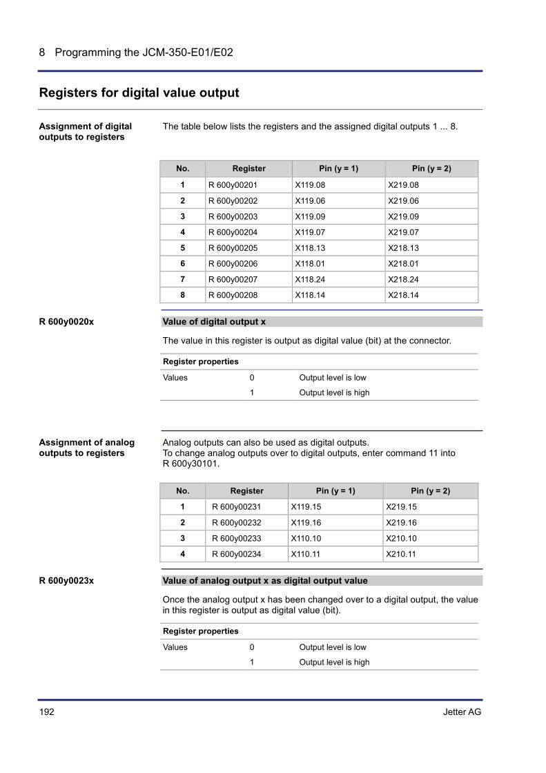
192 Jetter AG
8 Programming the JCM-350-E01/E02
Registers for digital value output
The table below lists the registers and the assigned digital outputs 1 ... 8.
No. Register Pin (y = 1) Pin (y = 2)
1 R 600y00201 X119.08 X219.08
2 R 600y00202 X119.06 X219.06
3 R 600y00203 X119.09 X219.09
4 R 600y00204 X119.07 X219.07
5 R 600y00205 X118.13 X218.13
6 R 600y00206 X118.01 X218.01
7 R 600y00207 X118.24 X218.24
8 R 600y00208 X118.14 X218.14
Value of digital output x
The value in this register is output as digital value (bit) at the connector.
Register properties
Values 0 Output level is low
1 Output level is high
Analog outputs can also be used as digital outputs. To change analog outputs over to digital outputs, enter command 11 into R 600y30101.
No. Register Pin (y = 1) Pin (y = 2)
1 R 600y00231 X119.15 X219.15
2 R 600y00232 X119.16 X219.16
3 R 600y00233 X110.10 X210.10
4 R 600y00234 X110.11 X210.11
Value of analog output x as digital output value
Once the analog output x has been changed over to a digital output, the value in this register is output as digital value (bit).
Register properties
Values 0 Output level is low
1 Output level is high
Assignment of digital outputs to registers
R 600y0020x
Assignment of analog outputs to registers
R 600y0023x

Jetter AG 193
JCM-350-E01/E02 Programming the JCM-350-E01/E02
PWM outputs can also be used as digital outputs. To change PWM outputs over to digital outputs, enter command 11 into R600y40101.
No. Register Pin (y = 1) Pin (y = 2)
1 R 600y00241 X119.24 X219.24
2 R 600y00242 X119.25 X219.25
3 R 600y00243 X119.26 X219.26
4 R 600y00244 X119.27 X219.27
5 R 600y00245 X118.34 X218.34
6 R 600y00246 X118.35 X218.35
7 R 600y00247 X110.12 X210.12
8 R 600y00248 X110.13 X210.13
Value of PMW output x as digital output value
Once the PWM output x has been changed over to a digital output, the value in this register is output as digital value (bit).
Register properties
Values 0 Output level is low
1 Output level is high
Connecting digital outputs (see page 70)
Assignment of PWM outputs to registers
R 600y0024x
Related topics

194 Jetter AG
8 Programming the JCM-350-E01/E02
8.3.2 Digital input 1 ... 11
This chapter describes how to use digital inputs. The application program lets you configure each digital input as Active-High input or as Active-Low input. Depending on the configuration the input channel may be inverted.
Command 11 lets you switch over analog inputs 1 ... 4 to digital inputs. If this function is used, the following thresholds apply:
All voltages at the analog input falling below 60 % of battery voltage are regarded as logic 0.
All voltages at the analog input exceeding 60 % of battery voltage are regarded as logic 1.
All currents at the analog input falling below 12 mA (60 % the maximum value of 20 mA) are regarded as logic 0.
All currents at the analog input exceeding 12 mA (60 % the maximum value of 20 mA) are regarded as logic 1.
To disable this function use command 12.
The table below shows how placeholders are used to address individual digital inputs. The following values are possible:
Placeholder Value Purpose
y 1 ... 2 I/O module 1 ... 2
x 1 ... 11 Digital input 1 ... 11
Topic Page Switching a digital input: Active-low or active-high. .................................... 195 Registers for retrieving digital values .......................................................... 197 Registers for retrieving analog values as digital values .............................. 198
Introduction
Analog inputs as digital inputs
Use of placeholders
Table of contents

Jetter AG 195
JCM-350-E01/E02 Programming the JCM-350-E01/E02
Switching a digital input: Active-low or active-high.
Take into account that addressing differs depending on the value of x.
If ... ... then ...
... x < 10 (x = 1 ... 9), ... use R 600y0015x.
... x = 10, ... use R 600y00160.
... x = 11, ... use R 600y00161.
Depending on the configuration (active-low or active-high) in register R 600y0015x the following switching statuses are possible:
Configuration Signal R 600y0015x
0 = Active-low input n.c. 0
24 V 0
0 V 1
1 = Active-high input n.c. 0
0 V 0
24 V 1
Note: "n.c." is short for "not connected".
Mode of digital inputs 1 ... 9
This value lets you define the operating mode of the digital inputs 1 ... 9: Active-low or active-high.
Register properties
Values 0 Input in active-low mode
1 Input in active-high mode
Exceptions with regard to addressing
Switching statuses
R 600y0015x

196 Jetter AG
8 Programming the JCM-350-E01/E02
Mode of digital input 10
This register lets you define the operating mode of digital input 10: Active-low or active-high.
Register properties
Values 0 Input in active-low mode
1 Input in active-high mode
Mode of digital input 11
This register lets you define the operating mode of digital input 11: Active-low or active-high.
Register properties
Values 0 Input in active-low mode
1 Input in active-high mode
R 600y00160
R 600y00161

Jetter AG 197
JCM-350-E01/E02 Programming the JCM-350-E01/E02
Registers for retrieving digital values
The table below lists the registers and the assigned digital inputs.
Number Register Pin (y = 1) Pin (y =2)
1 R 600y00101 X119.05 X219.05
2 R 600y00102 X119.04 X219.04
3 R 600y00103 X119.03 X219.03
4 R 600y00104 X118.25 X218.25
5 R 600y00105 X118.26 X218.26
6 R 600y00106 X118.27 X218.27
7 R 600y00107 X118.30 X218.30
8 R 600y00108 X118.31 X218.31
9 R 600y00109 X118.32 X218.32
10 R 600y00110 X118.23 X218.23
11 R 600y00111 X118.22 X218.22
Mode of digital input xx = 1 ... 11
The value in this register is retrieved as digital value (bit).
Register properties
Values 0 Input level is low
1 Input level is high
Connecting digital inputs (see page 67) Connecting digital frequency/pulse inputs (see page 65)
Assignment of digital inputs to registers
R 600y001xx
Related topics
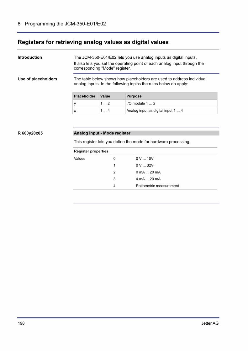
198 Jetter AG
8 Programming the JCM-350-E01/E02
Registers for retrieving analog values as digital values
The JCM-350-E01/E02 lets you use analog inputs as digital inputs. It also lets you set the operating point of each analog input through the corresponding "Mode" register.
The table below shows how placeholders are used to address individual analog inputs. In the following topics the rules below do apply:
Placeholder Value Purpose
y 1 ... 2 I/O module 1 ... 2
x 1 ... 4 Analog input as digital input 1 ... 4
Analog input - Mode register
This register lets you define the mode for hardware processing.
Register properties
Values 0 0 V ... 10V
1 0 V ... 32V
2 0 mA ... 20 mA
3 4 mA ... 20 mA
4 Ratiometric measurement
Introduction
Use of placeholders
R 600y20x05

Jetter AG 199
JCM-350-E01/E02 Programming the JCM-350-E01/E02
The threshold is set to 60 % of the maximum value. For current measurements this threshold is a fixed value, for voltage measurements it depends on the applied supply voltage.
Parameter Description
Voltage 60 % of supply voltage
Current 60 % of the maximum value of 20 mA = 12 mA
Evaluation of analog inputs used as digital inputs may differ depending on their mode.
If ... ... and ... ... then ...
... the mode is 0 ... 10 V, ... the measured analog value is < 60 % of supply voltage,
... the level is considered as digital "low".
... the mode is 0 ... 10 V, ... the measured analog value is > 60 % of supply voltage,
... the level is considered as digital "high".
... the mode is 0 ... 32 V, ... the measured analog value is < 60 % of supply voltage,
... the level is considered as digital "low".
... the mode is 0 ... 32 V, ... the measured analog value is > 60 % of supply voltage,
... the level is considered as digital "high".
... the mode is 0 ... 20 mA, ... the measured analog value is < 12 mA,
... the level is considered as digital "low".
... the mode is 0 ... 20 mA, ... the measured analog value is > 12 mA,
... the level is considered as digital "high".
... the mode is 4 ... 20 mA, ... the measured analog value is < 12 mA,
... the level is considered as digital "low".
... the mode is 4 ... 20 mA, ... the measured analog value is > 12 mA,
... the level is considered as digital "high".
... the mode is ratiometric, ... the measured analog value is < 60 % of supply voltage,
... the level is considered as digital "low".
... the mode is ratiometric, ... the measured analog value is > 60 % of supply voltage,
... the level is considered as digital "high".
Analog inputs - Threshold values

200 Jetter AG
8 Programming the JCM-350-E01/E02
Analog input 1 - Digital values
The value in this register is treated as digital value (bit) from analog input 1.
Register properties
Values 0 Signal is < 60 % of maximum value
1 Signal is > 60 % of maximum value
Analog input 2 - Digital values
The value in this register is treated as digital value (bit) from analog input 2.
Register properties
Values 0 Signal is < 60 % of maximum value
1 Signal is > 60 % of maximum value
Analog input 3 - Digital values
The value in this register is treated as digital value (bit) from analog input 3.
Register properties
Values 0 Signal is < 60 % of maximum value
1 Signal is > 60 % of maximum value
Analog input 4 - Digital values
The value in this register is treated as digital value (bit) from analog input 4.
Register properties
Values 0 Signal is < 60 % of maximum value
1 Signal is > 60 % of maximum value
Connecting analog inputs (see page 59)
R 600y00121
R 600y00122
R 600y00123
R 600y00124
Related topics

Jetter AG 201
JCM-350-E01/E02 Programming the JCM-350-E01/E02
8.3.3 Digital input 12 ... 15 (frequency input)
This chapter describes how digital frequency inputs are used. You cannot set these inputs as they are active-low inputs.
Topic Page Description of Registers: Retrieving frequency inputs ................................ 202
Introduction
Table of contents

202 Jetter AG
8 Programming the JCM-350-E01/E02
Description of Registers: Retrieving frequency inputs
The table below shows how placeholders are used to address individual frequency inputs. Throughout this chapter the following rules apply:
Placeholder Value Purpose
y 1 ... 2 I/O module 1 ... 2
Value of digital frequency input 1
This input can be regarded as logical input # 12. The physical input is frequency input # 1.
Register properties
Values 0 Input level is low
1 Input level is high
Value of digital frequency input 2
This input can be regarded as logical input # 13. The physical input is frequency input # 2.
Register properties
Values 0 Input level is low
1 Input level is high
Value of digital frequency input 3
This input can be regarded as logical input # 14. The physical input is frequency input # 3.
Register properties
Values 0 Input level is low
1 Input level is high
Register Addressing
R 600y00112
R 600y00113
R 600y00114

Jetter AG 203
JCM-350-E01/E02 Programming the JCM-350-E01/E02
Value of digital frequency input 4
This input can be regarded as logical input # 15. The physical input is frequency input # 4.
Register properties
Values 0 Input level is low
1 Input level is high
Connecting digital frequency/pulse inputs (see page 65)
R 600y00115
Related topics

204 Jetter AG
8 Programming the JCM-350-E01/E02
8.3.4 Frequency measurement
This chapter describes how to carry out frequency and pulse measurements using the JCM-350-E01/E02. The JCM-350-E01/E02 lets you toggle between pulse and frequency measurement using simple commands.
The table below shows how placeholders are used to address individual frequency inputs 1 ... 4. Throughout this chapter the following rules apply:
Placeholder Value Purpose
y 1 ... 2 I/O module 1 ... 2
x 1 ... 4 Frequency inputs 1 ... 4
Frequency measurement is split into the following two frequency bands:
0.5 Hz ... 500 Hz 500 Hz ... 50 kHz
For lower frequencies between 0.5 Hz and 500 Hz the period length is displayed in microseconds (µs). Frequency measurements in the frequency band between 500 Hz and 50 kHz are displayed in Hertz (Hz). The latter is the default setting.
The frequency measurement function lets you toggle between low and high frequency band. If the frequency is higher than 1 kHz, this function automatically switches over to the higher frequency band of 500 Hz ... 50 kHz.
Frequency Period Register Display
0.5 Hz 2 s 600y43x05 2,000,000
250 Hz 4 ms 600y43x05 4,000
500 Hz 2 ms 600y43x05 2,000
1 kHz 1 ms 600y43x05 -1
500 Hz 2 ms 600y43x03 500
20 kHz 50 µs 600y43x03 20,000
50 kHz 20 µs 600y43x03 50,000
60 kHz 16.67 µs 600y43x03 -1
Introduction
Use of placeholders
Frequency bands
Toggling between frequency bands

Jetter AG 205
JCM-350-E01/E02 Programming the JCM-350-E01/E02
Command 12 lets you activate the mode "pulse width measurement". Register R 600y43x08 lets you set the resolution (in microseconds) for pulse width measurements.
R 600y43x08 Resolution in µs Maximum period in ms
8 1 8.191
65 2 65.535
262 8 262
1048 32 1047
Topic Page Description of Registers: Frequency measurement ................................... 206
Measuring the pulse width
Table of contents

206 Jetter AG
8 Programming the JCM-350-E01/E02
Description of Registers: Frequency measurement
Status of frequency input x
The status indicates which mode is active at the moment.
R600y43x00
Bit 1 Period overflow for pulse width measurement
1 = Period overflow for
pulse width measurement frequency band 0.5 Hz ... 500 Hz
Bit 2 Period overflow for frequency measurement 1 kHz ... 60 kHz
1 = Overflow has occured: The measured frequency exceeds 60 kHz
Bit 10 Measuring range 0.5 Hz ... 500 Hz is enabled
1 = Status bit: Measuring range 0.5 Hz ... 500 Hz is enabled
Bit 11 Measuring range 500 Hz ... 50 kHz is enabled
1 = Status bit: Measuring range 500 Hz ... 50 kHz is enabled
Bit 12 Pulse width measurement is enabled
1 = Pulse width measurement is enabled
Register properties
Type of access Read access
Frequency input - Commands
Commands let you select low or high frequency band or pulse width measurement.
Command register
10 Command 10 lets you activate frequency band 0.5 Hz ... 500 Hz.
11 Command 11 lets you activate frequency band 500 Hz ... 50 kHz.
12 Command 12 lets you activate pulse width measurement. Command 10 or 11 lets you go back to frequency measurement.
22 Command 22 lets you clear all error bits in R 600y43x00.
R 600y43x00
R 600y43x01
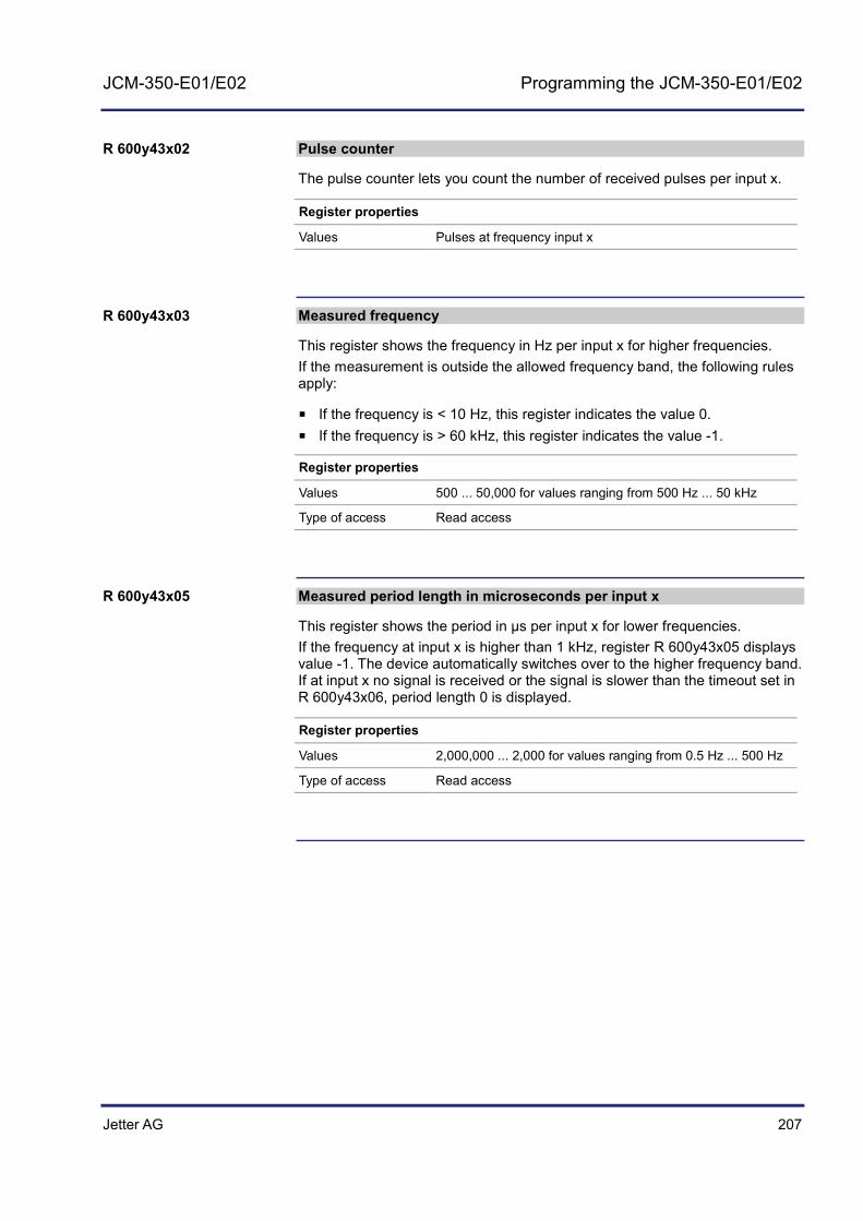
Jetter AG 207
JCM-350-E01/E02 Programming the JCM-350-E01/E02
Pulse counter
The pulse counter lets you count the number of received pulses per input x.
Register properties
Values Pulses at frequency input x
Measured frequency
This register shows the frequency in Hz per input x for higher frequencies. If the measurement is outside the allowed frequency band, the following rules apply:
If the frequency is < 10 Hz, this register indicates the value 0. If the frequency is > 60 kHz, this register indicates the value -1.
Register properties
Values 500 ... 50,000 for values ranging from 500 Hz ... 50 kHz
Type of access Read access
Measured period length in microseconds per input x
This register shows the period in µs per input x for lower frequencies. If the frequency at input x is higher than 1 kHz, register R 600y43x05 displays value -1. The device automatically switches over to the higher frequency band. If at input x no signal is received or the signal is slower than the timeout set in R 600y43x06, period length 0 is displayed.
Register properties
Values 2,000,000 ... 2,000 for values ranging from 0.5 Hz ... 500 Hz
Type of access Read access
R 600y43x02
R 600y43x03
R 600y43x05
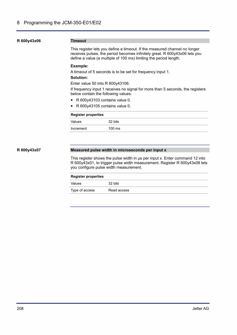
208 Jetter AG
8 Programming the JCM-350-E01/E02
Timeout
This register lets you define a timeout. If the measured channel no longer receives pulses, the period becomes infinitely great. R 600y43x06 lets you define a value (a multiple of 100 ms) limiting the period length.
Example: A timeout of 5 seconds is to be set for frequency input 1. Solution: Enter value 50 into R 600y43106. If frequency input 1 receives no signal for more than 5 seconds, the registers below contain the following values:
R 600y43103 contains value 0. R 600y43105 contains value 0.
Register properties
Values 32 bits
Increment 100 ms
Measured pulse width in microseconds per input x
This register shows the pulse width in µs per input x. Enter command 12 into R 600y43x01, to trigger pulse width measurement. Register R 600y43x08 lets you configure pulse width measurement.
Register properties
Values 32 bits
Type of access Read access
R 600y43x06
R 600y43x07

Jetter AG 209
JCM-350-E01/E02 Programming the JCM-350-E01/E02
Pulse width configuration
This register lets you configure the resolution for pulse width measurement. Resolution means the minimum internal time interval used by JCM-350-E01/E02 for pulse width measurement. The measuring range is independent of the output value in R 600y43x07.
Value Resolution Maximum measurable period length
8 1 µs 8.192 ms
65 2 µs 65.535 ms
262 8 µs 262 ms
1048 32 µs 1,047 ms
Register properties
Takes effect Once a value has been entered into the register.
Example: Set the value in R 600y43x08 to 262. The resolution has been set to 8 µs. Thus, the frequency input picks up signal level changes at an interval of 8 µs. The maximum measurable period length is a time interval; in the given case 262 ms.
Number Description
1 Any pulse at the frequency input
2 Resolution: here sampling interval of 8 µs
3 Maximum period length of measurement: here 262 ms
Connecting digital frequency/pulse inputs (see page 65)
R 600y43x08
Related topics

210 Jetter AG
8 Programming the JCM-350-E01/E02
8.3.5 PWM outputs 1 ... 8
This chapter describes how to use the PWM feature.
Topic Page Description of Registers: PWM outputs 1 ... 8 ............................................ 211
Introduction
Table of contents

Jetter AG 211
JCM-350-E01/E02 Programming the JCM-350-E01/E02
Description of Registers: PWM outputs 1 ... 8
The table below shows how placeholders are used to address PWM outputs 1 ... 8. Throughout this chapter the following rules apply:
Placeholder Value Purpose
y 1 ... 2 I/O module 1 ... 2
x 1 ... 8 PWM output 1 ... 8
Example: Addressing the setpoint (0 ... 100 %) of pulse width modulation for output 5 on I/O module 2: R 600240503
Status register of all 8 PWM outputs
This register indicates the status of the PWM outputs in bit-coded format.
Meaning of the individual bits
Bit 1 Status of PWM output 1
1 = Output is overloaded
Bit 2 Status of PWM output 2
1 = Output is overloaded
Bit 3 Status of PWM output 3
1 = Output is overloaded
Bit 4 Status of PWM output 4
1 = Output is overloaded
Bit 5 Status of PWM output 5
1 = Output is overloaded
Bit 6 Status of PWM output 6
1 = Output is overloaded
Bit 7 Status of PWM output 7
1 = Output is overloaded
Bit 8 Status of PWM output 8
1 = Output is overloaded
Register properties
Type of access Read access
Addressing PWM registers
R 600y40000

212 Jetter AG
8 Programming the JCM-350-E01/E02
Command register for all 8 PWM outputs
The global command register lets you clear the status "Overload" for all 8 PWM outputs.
Command
11 Enable PWM mode for digital output
12 Disable PWM mode for digital output
22 Clear the status "Overload" for all 8 PWM outputs
Status register of PWM output x
This status register indicates whether PWM is enabled or disabled.
Register properties
Values Bit 0 = 0 PWM disabled
Bit 0 = 1 PWM enabled
Command register of PWM output x
This command register lets you enable or disable PWM output x.
Commands
1 Enable PWM
2 Disable PWM
Period length of PWM output x
This register lets you set the period length for the PWM function.
Register properties
Values 12,000 ... 2,147,483,647 48,000 corresponds to a period length of 1 ms.
The period length may range from 250 µs to 44 s.
R 600y40001
R 600y40x00
R 600y40x01
R 600y40x02

Jetter AG 213
JCM-350-E01/E02 Programming the JCM-350-E01/E02
Setpoint of PWM output x
This register lets you define the setpoint. To set this value to its maximum (100 %), enter the value contained in register R 600y40x02 (maximum period length) into register R 600y40x03.
Register properties
Values 0 ... <R 600y40x02> 0 ... 100 % of R 600y40x02
Connecting PWM outputs (see page 75)
R 600y40x03
Related topics

214 Jetter AG
8 Programming the JCM-350-E01/E02
8.3.6 Relay outputs 1 ... 4
This chapter describes how to use and program relay outputs.
Topic Page Description of Registers: Relay outputs 1 ... 4 ............................................ 215
Introduction
Table of contents
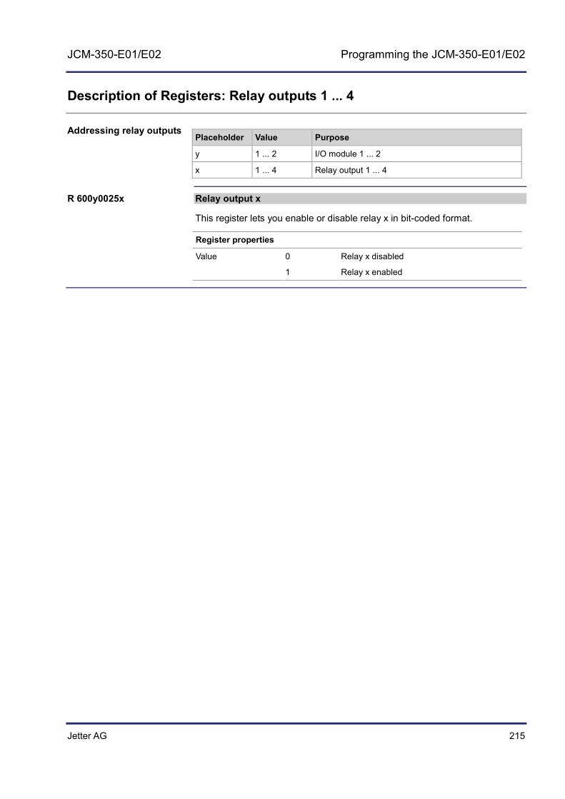
Jetter AG 215
JCM-350-E01/E02 Programming the JCM-350-E01/E02
Description of Registers: Relay outputs 1 ... 4
Placeholder Value Purpose
y 1 ... 2 I/O module 1 ... 2
x 1 ... 4 Relay output 1 ... 4
Relay output x
This register lets you enable or disable relay x in bit-coded format.
Register properties
Value 0 Relay x disabled
1 Relay x enabled
Addressing relay outputs
R 600y0025x

216 Jetter AG
8 Programming the JCM-350-E01/E02
8.3.7 H-bridges 1 ... 2
This chapter describes how to use and program H-bridges.
Depending on the application, you may use the H-bridge in digital or in analog mode. A simple command lets you toggle between digital and analog H-bridge mode.
The default H-bridge setting is analog mode.
Topic Page Description of Registers: H-bridge .............................................................. 217
Introduction
Table of contents

Jetter AG 217
JCM-350-E01/E02 Programming the JCM-350-E01/E02
Description of Registers: H-bridge
The table below shows how placeholders are used to address an H-bridge. Throughout this chapter the following rules apply:
Placeholder Value Purpose
y 1 ... 2 I/O module 1 ... 2
x 1 ... 2 H-bridge 1 ... 2
Example: To address the period length of the second H-bridge on I/O module 2, enter the following register number R 600242202
To commission an H-bridge in analog mode, proceed as follows:
Step Action
1 Set the period length in R 600y42102, and R 600y42202, e. g. by entering value 48,000 into R 600y42102, and value 50,000 into R 600y42202.
2 To activate the H-bridge, enter command 1 into R 600y42x01.
3 Enter the desired setpoint into R 600y42x03. For example, a setpoint ranging from -48,000 ... +48,000 for H-bridge 1, and a setpoint ranging from -50,000 ... +50,000 for H-Bridge 2.
Result: H-bridge 1 is controlled at a rate of 50 % in positive direction. H-bridge 2 is controlled at a rate of 25.6 % in negative direction.
To commission an H-bridge as digital output, proceed as follows:
Step Action
1 Enter command 11 into R 600y42x01 to switch over the H-bridge to "digital mode".
2 Depending on direction and behavior, configure the output as follows:
If ... ... then ...
... you wish to configure H-bridge x as high-side output, right-hand,
... enter command 13 into R 600y42x01.
... you wish to configure H-bridge x as low-side output, right-hand,
... enter command 14 into R 600y42x01.
... you wish to configure H-bridge x as high-side output, left-hand,
... enter command 15 into R 600y42x01.
... you wish to configure H-bridge x as low-side output, left-hand,
... enter command 16 into R 600y42x01.
3 To enable H-bridge x, enter command 1 into R 600y42x01.
H-bridge configuration is completed.
Addressing the H-bridge
Commissioning an H-bridge in analog mode
Commissioning an H-bridge in digital mode

218 Jetter AG
8 Programming the JCM-350-E01/E02
Step Action
4 Registers R 600y00261 ... R 600y00264 let you enable or disable H-bridge x.
H-bridge status
This register indicates the status of the H-bridges in bit-coded format.
Meaning of the individual bits
Bit 0 H-bridge enabled or disabled
0 = H-bridge is disabled
1 = H-bridge is enabled
Bit 2 Direction
0 = Negative direction
1 = Positive direction
Bit 3 Overload monitoring enabled or disabled
0 = Overload monitoring is disabled
1 = Overload monitoring is enabled
Bit 4 I2t overload monitoring
0 = No I²t overload
1 = I2t overload is present If this bit is set, the I²t value exceeds its limit. As a result, the output (H-bridge) gets disabled.
Bit 5 H-bridge as digital output
0 = The H-bridge is set to a value between 0 ... 100 %.
1 = H-bridge is configured to output 0 % or 100 %
Bit 6 H-bridge as digital output, right
0 = Low-side output, right
1 = High-side output, right
Bit 7 H-bridge as digital output, left
0 = Low-side output, left
1 = High-side output, left
Register properties
Type of access Read access
R 600y42x00

Jetter AG 219
JCM-350-E01/E02 Programming the JCM-350-E01/E02
Command register - H-bridges
This command register lets you set the H-bridge mode (digital or analog) and select the direction (positive or negative).
Commands
1 Enable H-bridge x
2 Disable H-bridge x
11 Enable mode "Digital output" for H-bridge x (fixed PWM setpoint of 100%)
12 Disable mode "Digital output" for H-bridge x
13 Enable mode "Digital output" for H-bridge x, low-side output, right
14 Enable mode "Digital output" for H-bridge x, high-side output, right
15 Enable mode "Digital output" for H-bridge x, low-side output, left
16 Enable mode "Digital output" for H-bridge x, high-side output, left
20 Positive direction
21 Negative direction
22 Acknowledge overload (clear short-circuit and I2t trip)
Setting/resetting the H-bridge as digital output
Once you have configured the H-bridge as digital output, you can set/reset the corresponding output in register R 600y00261 ... R 600y00264. If you enter the value 1 into one of these registers, the corresponding H-bridge is set as digital output. If you enter 0 into this register, the H-Bridge is reset. Note: It is not possible to set/reset the H-bridge as digital output in register R 600y42x03 H-bridge setpoint.
Register Description
R 600y00261 H-bridge 1, right
R 600y00262 H-bridge 1, left
R 600y00263 H-bridge 2, right
R 600y00264 H-bridge 2, left
If a signed setpoint is used, commands 20 and 21 are not required.
R 600y42x01
R 600y0026x
Note on "Analog mode"

220 Jetter AG
8 Programming the JCM-350-E01/E02
H-bridge period length
This register lets you set the period length of the H-bridge.
Register properties
Values 12,000 ... 2,147,483,647 20,833 ns
48,000 corresponds to a period length of 1 ms. The period length may range from 250 µs to 44 s.
H-bridge setpoint
This register lets you define the setpoint of the H-bridges (+/- | 0 ... 100 % | ). For example, to set this value to its maximum (100 %), enter the value contained in register R 600y40x02 (maximum period length) into register R 600y40x03. Evaluation of register 600y42x03 is sign-dependent. A positive value causes the motor to rotate forwards. A negative value causes the motor to rotate backwards.
Register properties
Values +/- | 0 ... maximum in <R 600y42x02> |
-100 % ... 100 %
H-bridge I2t overcurrent protection
This register shows the average power dissipation of the H-bridge. The I2t calculation is based on a model that is in proportion to the actual power dissipation.
Register properties
Values 0 ... 100 0 % ... 100 %
Current measurement - H-bridge 1
Register R 600y22903 shows the current for H-bridge 1 in mA.
Register properties
Values Displayed in mA e. g. 1,000 representing 1 A
R 600y42x02
R 600y42x03
R 600y42x06
R 600y22903

Jetter AG 221
JCM-350-E01/E02 Programming the JCM-350-E01/E02
Current measurement - H-bridge 2
Register R 600y23003 shows the current for H-bridge 2 in mA.
Register properties
Values Displayed in mA e. g. 1,000 representing 1 A
Connecting H-bridges (see page 73)
R 600y23003
Related topics

222 Jetter AG
8 Programming the JCM-350-E01/E02
8.4 Programming analog inputs and outputs
This chapter describes how analog voltage and current signals are processed.
Each analog input and output can be configured regardless of the configuration of the other analog inputs and outputs.
Topic Page A/D converter - Converting electrical signals into digital values ................. 223 D/A conversion - Converting digital values into electrical signals ............... 229
Introduction
Independency
Table of contents

Jetter AG 223
JCM-350-E01/E02 Programming the JCM-350-E01/E02
8.4.1 A/D converter - Converting electrical signals into digital values
This chapter describes how electrical signals are converted into digital values.
Topic Page Converting analog voltages into digital values ........................................... 224 Configuring A/D conversion for several measuring ranges ........................ 225 Description of Registers: Converting analog values into digital values ...... 226 Description of Registers: Analog current/voltage values ............................ 228
Introduction
Table of contents

224 Jetter AG
8 Programming the JCM-350-E01/E02
Converting analog voltages into digital values
The A/D converter converts electrical levels at analog inputs of pin X119 and X219 to digital values.
The illustration below shows the process of A/D conversion. Register R 600y20x05 lets you configure individual channels.
R 600y20x05
X y19.04
X y19.13
X y19.02
X y19.01
AD
AD
AD
AD
AD
AD
AD
y = 1: JCM-350-E01-xxxy = 2: JCM-350-E02-xxx
12
3
4
0..10V0..32V0..20mA4..20mA
R 600y20102
0..10V0..32V0..20mA4..20mA
R 600y20202
0..10V0..32V0..20mA4..20mA
R 600y20302
0..10V0..32V0..20mA4..20mA
R 600y20402
Cha
nnel
1C
hann
el 2
Cha
nnel
3C
hann
el 4
MulDiv
-Ofsa =n R 600y21103
MulDiv
-Ofsa =n R 600y21203
MulDiv
-Ofsa =n R 600y21303
MulDiv
-Ofsa =n R 600y21403
56
x = 1 .. 4
No. Description
1 Connector X119 or connector X219
2 Individual A/D conversion, 12-bit; values 0 ... 4,095
3 R 600y20x05 for selecting the corresponding channel
4 R 600y20x02 containing the uncalibrated result
5 Calibration depending on mode
6 R 600y20x03 containing the calibrated result. Where x = 1 ... 4
Introduction
A/D conversion
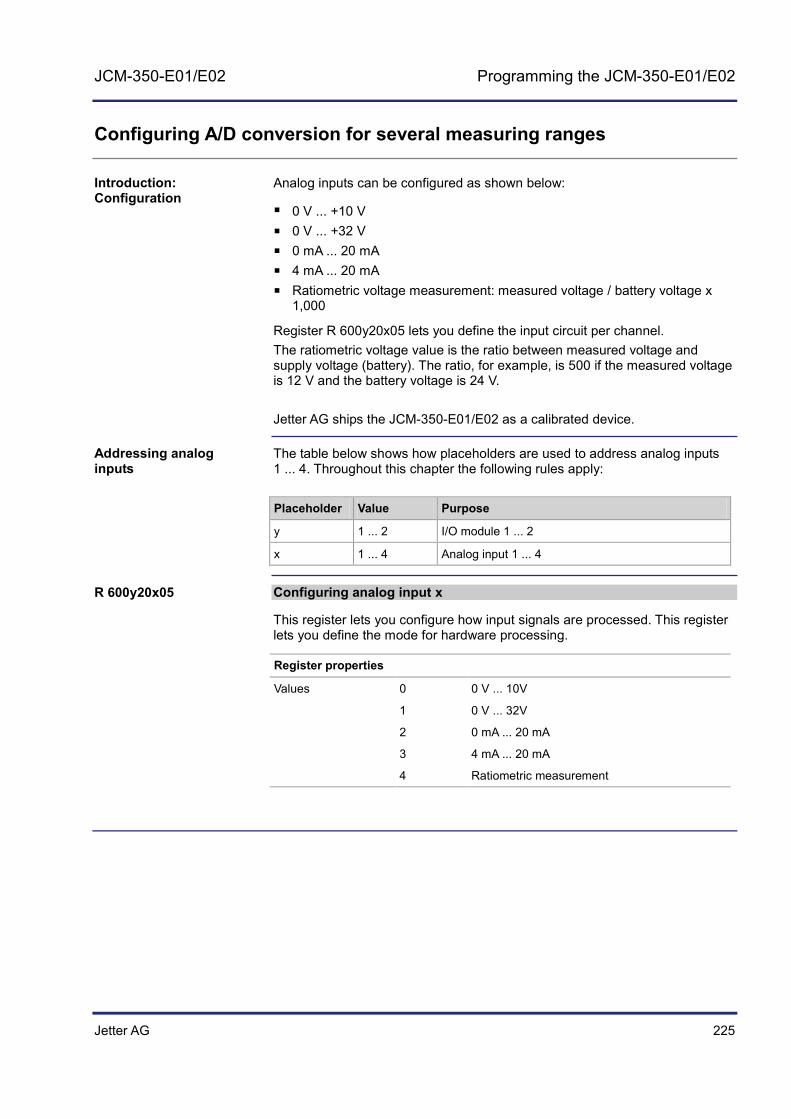
Jetter AG 225
JCM-350-E01/E02 Programming the JCM-350-E01/E02
Configuring A/D conversion for several measuring ranges
Analog inputs can be configured as shown below:
0 V ... +10 V 0 V ... +32 V 0 mA ... 20 mA 4 mA ... 20 mA Ratiometric voltage measurement: measured voltage / battery voltage x
1,000
Register R 600y20x05 lets you define the input circuit per channel. The ratiometric voltage value is the ratio between measured voltage and supply voltage (battery). The ratio, for example, is 500 if the measured voltage is 12 V and the battery voltage is 24 V. Jetter AG ships the JCM-350-E01/E02 as a calibrated device.
The table below shows how placeholders are used to address analog inputs 1 ... 4. Throughout this chapter the following rules apply:
Placeholder Value Purpose
y 1 ... 2 I/O module 1 ... 2
x 1 ... 4 Analog input 1 ... 4
Configuring analog input x
This register lets you configure how input signals are processed. This register lets you define the mode for hardware processing.
Register properties
Values 0 0 V ... 10V
1 0 V ... 32V
2 0 mA ... 20 mA
3 4 mA ... 20 mA
4 Ratiometric measurement
Introduction: Configuration
Addressing analog inputs
R 600y20x05

226 Jetter AG
8 Programming the JCM-350-E01/E02
Description of Registers: Converting analog values into digital values
Status of analog input x
If the mode is "4 ... 20 mA", this register shows whether the value is less than 4 mA. This feature lets you detect no-load conditions, such as a broken cable. This bit is set if the current falls below 4 mA. If you enter the value 0 into register R 600y20x00, the bit is cleared.
Register properties
Values Bit 0 = 1 The value in R 600y20x03 is less than 4,000, i.e. 4 mA
Value of the measured input signal
This register contains the measured physical value of the analog input depending on the set mode.
Register properties
Values The content of this register depends on the mode set.
R 600y20x00
R 600y20x03

Jetter AG 227
JCM-350-E01/E02 Programming the JCM-350-E01/E02
Configuring the A/D channel
To switch over the configuration of analog input x, enter a value between 0 ... 4 into register R 600x20x05.
Register properties
Register Values Configuration
R 600y20x05 = 0 0 ... 10,000 0 ... 10 V
R 600y20x05 = 1 0 ... 32,000 0 ... 32 V
R 600y20x05 = 2 0 ... 20,000 0 ... 20 mA
R 600y20x05 = 3 0 ... 20,000 4 ... 20 mA
R 600y20x05 = 4 0 ... 1,000 Ratiometric
Connecting analog inputs (see page 59)
R 600y20x05
Related topics
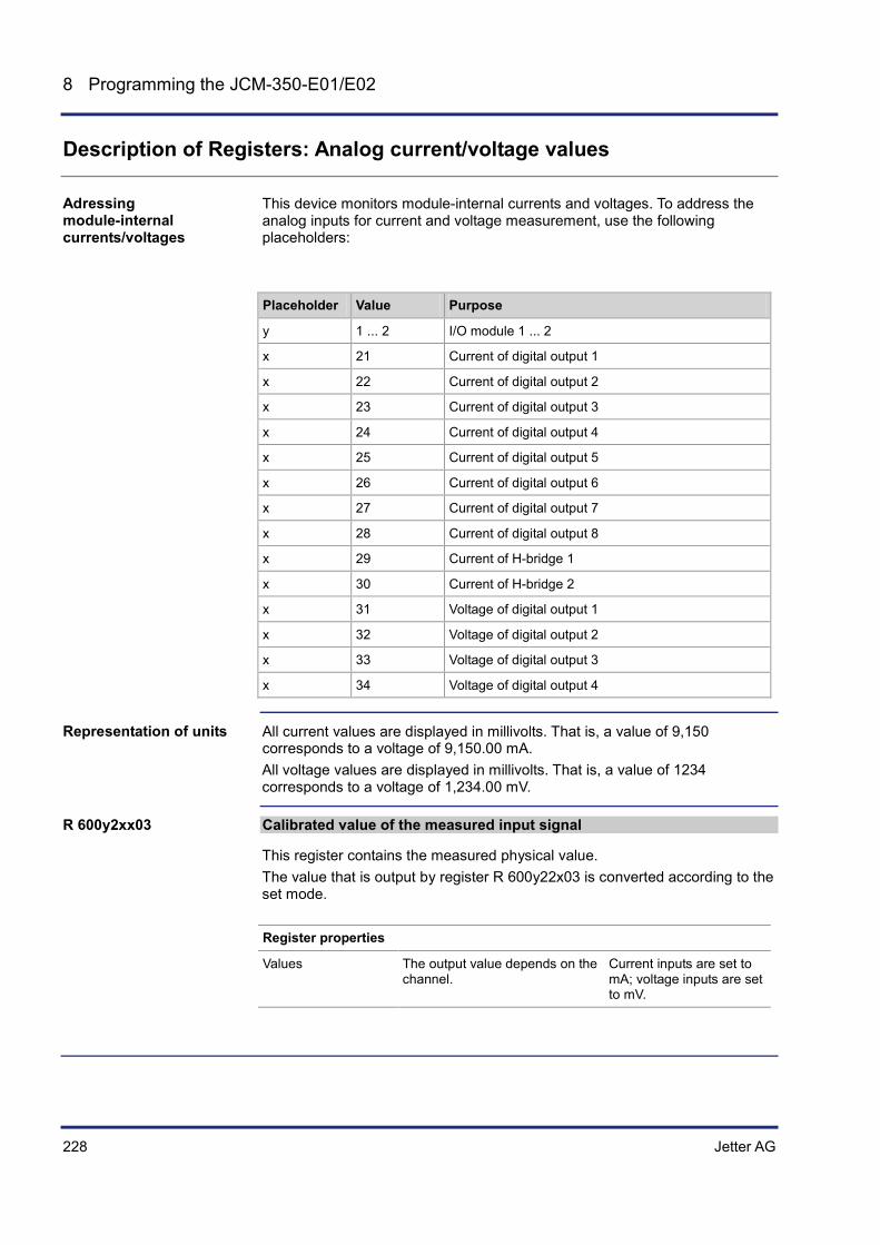
228 Jetter AG
8 Programming the JCM-350-E01/E02
Description of Registers: Analog current/voltage values
This device monitors module-internal currents and voltages. To address the analog inputs for current and voltage measurement, use the following placeholders:
Placeholder Value Purpose
y 1 ... 2 I/O module 1 ... 2
x 21 Current of digital output 1
x 22 Current of digital output 2
x 23 Current of digital output 3
x 24 Current of digital output 4
x 25 Current of digital output 5
x 26 Current of digital output 6
x 27 Current of digital output 7
x 28 Current of digital output 8
x 29 Current of H-bridge 1
x 30 Current of H-bridge 2
x 31 Voltage of digital output 1
x 32 Voltage of digital output 2
x 33 Voltage of digital output 3
x 34 Voltage of digital output 4
All current values are displayed in millivolts. That is, a value of 9,150 corresponds to a voltage of 9,150.00 mA. All voltage values are displayed in millivolts. That is, a value of 1234 corresponds to a voltage of 1,234.00 mV.
Calibrated value of the measured input signal
This register contains the measured physical value. The value that is output by register R 600y22x03 is converted according to the set mode.
Register properties
Values The output value depends on the channel.
Current inputs are set to mA; voltage inputs are set to mV.
Adressing module-internal currents/voltages
Representation of units
R 600y2xx03
Jetter AG 229
JCM-350-E01/E02 Programming the JCM-350-E01/E02
8.4.2 D/A conversion - Converting digital values into electrical signals
This chapter describes how digital values are converted into electrical signals. You can configure D/A conversion as follows:
Analog output Digital output
An analog value is output either as minimum, or as maximum.
Topic Page Digital/analog conversion ........................................................................... 230 Registers for digital-to-analog conversion .................................................. 231
Introduction
Table of contents

230 Jetter AG
8 Programming the JCM-350-E01/E02
Digital/analog conversion
The D/A converter converts digital values into analog voltages.
The illustration below shows how D/A conversion works:
X y19.15CH1
CH2
CH3
CH4
X y10.10
X y10.11
y = 1: JCM-350-E01-xxxy = 2: JCM-350-E02-xxx
PWM1
PWM2
PWM3
PWM4
State,CommandPeriodSetpoint
State,CommandPeriodSetpoint
State,CommandPeriodSetpoint
State,CommandPeriodSetpoint
1 2 3
No. Description
1 Registers for configuring the related D/A channel
2 The underlying D/A conversion
3 Analog output pins, e.g. X210.10 (channel 3)
Introduction
D/A conversion

Jetter AG 231
JCM-350-E01/E02 Programming the JCM-350-E01/E02
Registers for digital-to-analog conversion
Placeholder Values Purpose
y 1 ... 2 I/O module 1 ... 2
x 1 ... 4 D/A channel 1 ... 4
z 0 Status
z 1 Command
z 3 Set value
z 5 Mode switching
Addressing an output
600y30x0z where x = 1 - D/A output 1
600y30x0z where x = 2 - D/A output 2
600y30x0z where x = 3 - D/A output 3
600y30x0z where x = 4 - D/A output 4
Example: D/A output 3 on I/O module 2 is to be set to 16 V: 600230303 := 16000;
Command 11 lets you switch over from analog output mode to digital. If the output mode of the D/A converter has been set to digital, the output value is either 0, or 1. Command 12 lets you switch over from digital to analog output mode.
Status of D/A output x
This register returns the status of D/A conversion for output x.
Register properties
Values Bit 0 = 0 Analog output disabled
Bit 0 = 1 Analog output enabled
Addressing analog outputs
Addressing an D/A output
Switching over from analog to digital output
R 600y30x00

232 Jetter AG
8 Programming the JCM-350-E01/E02
Command register for D/A conversion
This register lets you enable, disable or switch over D/A conversion.
Commands
1 Enable mode "Analog output"
2 Disable mode "Analog output"
11 Switch over from mode "Analog output" to "Digital output": The analog value is output either as 0, or maximum value.
12 Disable mode "Digital output"
Register "Setpoint" for D/A output x
This register contains the setpoint
Register properties
Values 0 ... 10,000 0 ... 10 V
0 ... 32,000 0 ... 32 V
Mode 0 ... 10 V or 0 ... 32 V
This register lets you select the mode. To enable a voltage output of up to 32 V, enter 1.
Register properties
Values 0 0 ... 10 V
1 0 ... 32 V
Connecting analog outputs (see page 61)
R 600y30x01
R 600y30x03
R 600y30x05
Related topics
Jetter AG 233
JCM-350-E01/E02 Betriebssystemupdate
9 Betriebssystemupdate
Jetter AG are continuously striving to enhance the operating systems for their controllers and peripheral modules. Enhancing means adding new features, upgrading existing functions and fixing bugs. This chapters describes how to perform an operating system update for a system equipped with a JCM-350-E01/E02 controller.
You can download operating systems from the Jetter AG homepage at www.jetter.de http://www.jetter.de. You get to the OS files by clicking on the quick link "Operating System Download" on the website of the corresponding controller or module.
The operating system of the following mobile controllers can be updated:
Controller JCM-350-E01/E02
Topic Page Updating the Operating System of the Controller ....................................... 234
Introduction
Downloading an Operating System
Mobile controllers
Contents

234 Jetter AG
9 Betriebssystemupdate
9.1 Updating the Operating System of the Controller
This chapter describes how to update the OS of the controller JCM-350-E01/E02. To transfer the OS file to the controller the following options are available:
From within the programming tool JetSym
Topic Page OS update by means of JetSym ................................................................. 235
Introduction
Contents

Jetter AG 235
JCM-350-E01/E02 Betriebssystemupdate
OS update by means of JetSym
The programming tool JetSym offers an easy way to transfer an OS file to the JCM-350-E01/E02.
An OS file for the JCM-350-E01/E02 must be available. An active CAN connection between JetSym and the device is set up. During booting, the controller is waiting for the OS update (boot loader), or
the OS is already running. The controller must not be de-energized during the OS update process.
To update the OS, proceed as follows:
Step Action
1 In JetSym, click on the menu Build and select item Update OS..., or click in the configuration window of the Hardware Manager on OS Update. Result: The file selection dialog opens.
2 Select the new OS file here. Result: In JetSym, a confirmation dialog opens.
3 Launch the OS upload by clicking the button Yes.
4 Wait until the update process is completed.
5 To activate the transferred OS, re-boot the controller.
Introduction
Prerequisites
Updating the OS


Jetter AG 237
JCM-350-E01/E02 Quick reference - JCM-350
10 Quick reference - JCM-350
Operating system version
This quick reference summarizes the registers and flags of the controller JCM with OS version 1.12.0.06
General overview - Registers
100000 ... 100999 Electronic Data Sheet (EDS) 101000 ... 101999 Configuration
200000 ... 209999 General system registers 210000 ... 219999 Application program 310000 ... 319999 File system / data files
1000000 ... 1005999 JCM-350: Application registers (remanent; Int/Float)
General overview - Flags
0 ... 255 Application flags (remanent) 256 ... 2047 Overlaid by registers 1000000 through
1000055 2048 ... 2303 Special flags
Electronic Data Sheet (EDS)
100500 Interface (0 = CPU) [Identification] 100600 Internal version number 100601 Module ID 100602 ... 100612
Module name (register string)
100613 PCB revision 100614 PCB options [Production] 100700 Internal version number 100701 ... 100707
Serial number (register string)
100708 Day 100709 Month 100710 Year 100711 TestNum. 100712 TestRev. [Features] I/O Module
100808 Features 100809 Diagnostics mask [Features] JCM-350 100800 Internal version number 100801 MAC Address (Jetter) 100802 MAC Address (device) 100803 Serial port 100804 Switch 100805 STX 100806 Remanent registers 100808 CAN bus 100811 Intelligent slave modules 100812 HTTP / e-mail 100813 Modbus/TCP 100817 RTC 100992 Item number 100993 Hardware revision of the device as a whole
Configuration
From file /system/config.ini
101100 IP address
101101 Subnet mask 101102 Default gateway 101103 DNS server 101132 Host name suffix type 101133 ... 101151
Host name (register string)
101164 JetIP port number 101165 STX debugger port number Used by the system
101200 IP address 101201 Subnet mask 101202 Default gateway 101203 DNS server 101232 Host name suffix type 101233 ... 101251
Host name (register string)
101264 JetIP port number 101265 STX debugger port number
General system registers
200000 OS version (major * 100 + minor) 200001 Application program is running (bit 0 = 1) 200008 Error register (identical with 210004) Bit 1: Error on JX3 bus
Bit 2: Error on JX2 bus
Bit 8: Illegal jump
Bit 9: Illegal call
Bit 10: Illegal index
Bit 11: Illegal opcode
Bit 12: Division by 0
Bit 13: Stack overflow
Bit 14: Stack underflow
Bit 16: Error when loading application program
Bit 24: Timeout - cycle time
Bit 25: Timeout - task lock
Bit 31: Unknown error
200168 Bootloader version (IP format) 200169 OS version (IP format) 200170 Controller type (340/350) 201000 Runtime registers in milliseconds (rw) 201001 Runtime registers in seconds (rw) 201002 Runtime register in register 201003 Units (rw)
201003 * 10 ms units for register 201002 (rw) 201004 Runtime registers in milliseconds (ro) 202930 Web status (bit-coded) Bit 0 = 1: FTP server available
Bit 1 = 1: HTTP-server available
Bit 2 = 1: E-mail available
Bit 3 = 1: Data file function available
Bit 4 = 1: Modbus/TCP has been licensed
Bit 5 = 1: Modbus/TCP available
Bit 6 = 1: Ethernet/IP available
202936 Control register - File System 0xc4697a4b: Formatting the flash disk
202960 Password for system command register (0x424f6f74) 202961 System command register

238 Jetter AG
10 Quick reference - JCM-350
202980 Error history: Number of entries 202981 Error history: Index 202982 Error history: Entry 203000 Interface monitoring: JetIP 203001 Interface monitoring: SER 203005 Interface monitoring: Debug server 203100 ... 203107
32-bit overlaying - Flag 0 ... 255
203108 ... 203123
16-bit overlaying - Flag 0 ... 255
203124 ... 203131
32-bit overlaying - Flag 2048 ... 2303
203132 ... 203147
16-bit overlaying - Flag 2048 ... 2303
209700 System logger: Global enable 209701 ... 209739
Enabling system components
Application program
210000 Application program is running (bit 0 = 1) 210004 Error register (bit-coded) Bit 1: Error on JX3 bus
Bit 2: Error on JX2 bus
Bit 8: Illegal jump
Bit 9: Illegal call
Bit 10: Illegal index
Bit 11: Illegal opcode
Bit 12: Division by 0
Bit 13: Stack overflow
Bit 14: Stack underflow
Bit 15: Illegal stack
Bit 16: Error when loading application program
Bit 24: Timeout - cycle time
Bit 25: Timeout - task lock
Bit 31: Unknown error
210006 Highest task number 210007 Minimum program cycle time 210008 Maximum program cycle time 210009 Current program cycle time 210011 Current task number 210050 Current program position within a execution unit 210051 ID of the execution unit being processed 210056 Desired total cycle time in µs 210057 Calculated total cycle time in µs 210058 Maximum time slice per task in µs 210060 Task ID (for register 210061) 210061 Task priority for the task [reg. 210060] 210063 Length of scheduler table 210064 Index in scheduler table 210065 Task ID in scheduler table 210070 Task ID (for register 210071) 210071 Timer number (0 ... 31) 210072 Manual triggering of a timer event (bit-coded) 210073 End of cyclic task (task ID) 210074 Command for cyclic tasks 210075 Number of timers 210076 Timer number (for register 210077) 210077 Timer value in milliseconds 210100 ... 210199
Task state
210400 ... 210499
Task - programm address
210600 Task ID of a cyclic task (for register 210601) 210601 Processing time of a cyclical task in per mil figure 210609 Task lock timeout in ms -1: Monitoring disabled
210610 Timeout (bit-coded, bit 0 -> timer 0, etc.)
File system / data file function
312977 Status of file operation 312978 Task ID
Application Registers
1000000 ... 1005999
JC-350: 32-bit integer or floating point number (remanent)
Special flags - Interface monitoring
2088 OS flag - JetIP 2089 User flag - JetIP 2090 OS flag - SER 2091 User flag - SER 2098 OS flag - Debug server 2099 User flag - Debug server
32 combined flags
203100 0 ... 31 203101 32 ... 63 203102 64 ... 95 203103 96 ... 127 203104 128 ... 159 203105 160 ... 191 203106 192 ... 223 203107 224 ... 255
16 combined flags
203108 0 ... 15 203109 16 ... 31 203110 32 ... 47 203111 48 ... 63 203112 64 ... 79 203113 80 ... 95 203114 96 ... 111 203115 112 ... 127 203116 128 ... 143 203117 144 ... 159 203118 160 ... 175 203119 176 ... 191 203120 192 ... 207 203121 208 ... 223 203122 224 ... 239 203123 240 ... 255
32 combined special flags
203124 2048 ... 2079 203125 2080 ... 2111 203126 2112 ... 2143 203127 2144 ... 2175 203128 2176 ... 2207 203129 2208 ... 2239 203130 2240 ... 2271 203131 2272 ... 2303

Jetter AG 239
JCM-350-E01/E02 Quick reference - JCM-350
16 combined special flags
203132 2048 ... 2063 203133 2064 ... 2079 203134 2080 ... 2095 203135 2096 ... 2111 203136 2112 ... 2127 203137 2128 ... 2143 203138 2144 ... 2159 203139 2160 ... 2175 203140 2176 ... 2191 203141 2192 ... 2207 203142 2208 ... 2223 203143 2224 ... 2239 203144 2240 ... 2255 203145 2256 ... 2271 203146 2272 ... 2287 203147 2288 ... 2303
Overlaid application registers/flags
1000000 256 ... 287 1000001 288 ... 319 1000002 320 ... 351 1000003 352 ... 383 1000004 384 ... 415 1000005 416 ... 447 1000006 448 ... 479 1000007 480 ... 511 1000008 512 ... 543 1000009 544 ... 575 1000010 576 ... 607 1000011 608 ... 639 1000012 640 ... 671 1000013 672 ... 703 1000014 704 ... 735 1000015 736 ... 767 1000016 768 ... 799 1000017 800 ... 831 1000018 832 ... 863 1000019 864 ... 895 1000020 896 ... 927 1000021 928 ... 959 1000022 960 ... 991 1000023 992 ... 1023 1000024 1024 ... 1055 1000025 1056 ... 1087 1000026 1088 ... 1119 1000027 1120 ... 1151 1000028 1152 ... 1183 1000029 1184 ... 1215 1000030 1216 ... 1247 1000031 1248 ... 1279 1000032 1280 ... 1311 1000033 1312 ... 1343 1000034 1344 ... 1375 1000035 1376 ... 1407 1000036 1408 ... 1439 1000037 1440 ... 1471 1000038 1472 ... 1503 1000039 1504 ... 1535 1000040 1536 ... 1567 1000041 1568 ... 1599 1000042 1600 ... 1631 1000043 1632 ... 1663 1000044 1664 ... 1695 1000045 1696 ... 1727 1000046 1728 ... 1759 1000047 1760 ... 1791 1000048 1792 ... 1823 1000049 1824 ... 1855 1000050 1856 ... 1887 1000051 1888 ... 1919 1000052 1920 ... 1951 1000053 1952 ... 1983 1000054 1984 ... 2015 1000055 2016 ... 2047
System Functions
4 Conversion from BCD to HEX 5 Conversion from HEX to BCD 20 Square root 21 Sine 22 Cosine 23 Tangent 24 Arc Sine 25 Arc cosine 26 Arc tangent 27 Exponential function 28 Natural logarithm 29 Absolute value 30 Separation of digits before and after the decimal point 60 CRC generation for Modbus RTU 61 CRC check for Modbus RTU 65/67 Reading register block via Modbus/TCP 66/68 Writing register block via Modbus/TCP 80/85 Initializing RemoteScan 81 Starting RemoteScan 82 Stopping RemoteScan 90 Writing data file 91 Appending data file 92 Reading data file 96 Deleting data file 110 E-mail feature 150 Configuring NetCopyList 151 Deleting NetCopyList 152 Sending NetCopyList

240 Jetter AG
10 Quick reference - JCM-350

Jetter AG 241
JCM-350-E01/E02 Quick reference - JCM-350-E01/E02, I/O module
11 Quick reference - JCM-350-E01/E02, I/O module
Operating system version
This quick reference summarizes the registers of the I/O modules on a JCM-350-E01/E02 with OS version 1.00.0.76 or higher.
Placeholder definition
The register numbers used in this chapter contain placeholders. They make it easier to search for similar functions shifted by an offset. The following rule applies: y = 1 for I/O module 1 y = 2 for I/O module 2
Default addresses
The JCM-350-E01/E02 is shipped with the following default address: Node ID: 127 (0x7F)
General overview - Registers
600y00000 Status of digital output: Bit 0 = 1: Collective message "Short circuit" Bit 1 ... Bit 8: Short circuit of digital output 1 ... 8
600y44000 Module state 600y44001 Module command
600y44010 Battery voltage 600y44030 BER_Signal 600000400.0 Status bit 0 = 1: Communication enabled - I/O module 1 600000400.1 Status bit 1 = 1: Communication enabled - I/O module 2 600000401 Command 11: Enabling communication - I/O module 1
Command 12: Enabling communication - I/O module 2 600000020 Launching STX program with value 0 = Stop
value 1 = Run
value 2 = Load
600000010 Timeout counter - Data protocol 600000011 FCS error counter - Data protocol
104531 Changing the IP address (remanent) 104532 Changing the IP mask (remanent) 104533 Changing the IP gateway (remanent)
Description of registers - Control panel
600000312 Keyboard, bit-coded Bit 0 = 1: Key "F1" pressed
Bit 7 = 1: Key "F8" pressed
Bit 8 = 1: Key "Mode" pressed
600000320 LED green, bit-coded Bit 0 = 1: Node
Bit 1 = 1: Supply
Bit 2 = 1: Failure
Bit 3 = 1: CAN5
Bit 4 = 1: CAN4
Bit 5 = 1: CAN3
Bit 6 = 1: CAN2
Bit 7 = 1: CAN1
600000321 LED red, bit-coded Bit 0 = 1: Node
Bit 1 = 1: Supply
Bit 2 = 1: Failure
Bit 3 = 1: CAN5
Bit 4 = 1: CAN4
Bit 5 = 1: CAN3
Bit 6 = 1: CAN2
Bit 7 = 1: CAN1
600000322 LED green, bit-coded Bit 0 = 1: Run/Config/Teach
600000323 LED red, bit-coded
Bit 0 = 1: Run/Config/Teach
Command register - I/O module
600y44001 Command register
Command 1: Energizing all I/O components
Command 2: De-energizing all I/O components
Command 11: Enabling communication - I/O module 1
Command 12: Enabling communication - I/O module 2
Command 29: Clearing current error bits in R 600y44031
Basic address sorted by functional blocks
600y20102 Analog/digital conversion 600y30100 Digital/analog conversion 600y00201 Digital outputs 600y001xx Digital inputs 600y43103 Frequency measurement 600y44000 Global registers 600y42100 H-bridge 600y40000 PWM outputs, digital 600y00251 Relay outputs
Analog inputs
600y20102 Input 1 - Results register 600y20202 Input 2 - Results register 600y20302 Input 3 - Results register 600y20402 Input 4 - Results register
Digital outputs
600y0000x Overload I2t - Output x
600y0020x Output x 0 = Output disabled
1 = Output enabled
x = 1 ... 8: Output 1 ... 8
y = 1: I/O module 1
y = 2: I/O module 2
600y0023x Analog output 1 ... 4 as digital output x = 1 ... 4: Following switchover output can be used as
digital output

242 Jetter AG
11 Quick reference - JCM-350-E01/E02, I/O module
600y0024x PWM output as digital output x = 1 ... 8: Following switchover output can be used as
digital output
600y01000 Status of I2t overcurrent protection bit 1 ... 8 600y0100x Value of I2t overcurrent protection per output x x = 1 ... 8: Output 1 ... 8
600y01011 Command register for digital outputs Command 22: Reset short-circuit and I2t
Digital inputs
600y001xx Input xx Value 0: Enabling input (active-low) at 0 V
Value 1: Disabling input (active-low) at 24 V or n.c.
Value 0: Disabling input (active-high) at 0 V or n.c.
Value 1: Enabling input (active-high) at 24 V
Active-high: R 600y0015x = 1
Active-low: R 600y0015x = 0
Range R 600y00151 ... R 600y00161
n.c. = not connected
xx = 1 ... 11: Input 1 ... 11
y = 1: I/O module 1 y = 2: I/O module 2
Frequency measurement
600y43x00 Frequency status Bit 1 = 1: Period overflow for pulse width measurement
Measuring range 0.5 ... 500 Hz Bit 2 = 1: Overflow: The measured frequency exceeds
60 kHz Bit 10 = 1: Measuring range 0.5 Hz ... 500 Hz enabled
Bit 11 = 1: Measuring range 500 Hz ... 50 kHz enabled
Bit 12 = 1: Pulse-width measurement is enabled
600y43x01 Command register Command 10: Set measuring range to 0.5 ... 500 Hz
Command 11: Set measuring range to 500 Hz ... 50 kHz
Command 12: Enable pulse-width measurement
Command 22: Clear all error bits in R 600y43x00
600y43x02 Pulse counter 600y43x03 Measured frequency in Hz 600y43x05 Measured period in µs 600y43x06 Timeout: 16-bit counter, unit is ms, e.g. 100 ms grid
period limitation 600y43x07 Measured pulse width in µs 600y43x08 Pulse width configuration Value Resolution Measuring range
8 1 µs 8,192 ms
65 2 µs 65,535 ms
262 8 µs 262 ms
1048 32 µs 1,047 s
x = 1 ... 4: Output 1 ... 4
Value range: 0.5 Hz ... 50 kHz
PWM outputs 1 ... 8
600y40x00 Global status register Bit 0 = 0: PWM disabled
Bit 0 = 1: PWM enabled
600y40x01 Command register 600y40x02 PWM period length 48,000 corresponds to a period length of 1 ms.
600y40x03 PWM setpoint (0 ... 100 %) where x = 1 ... 8: Output 1 ... 8
Relay outputs 1 ... 4
600y00251 Relay output 1 Value 0: Relay output open
Value 1: Relay output closed
600y00252 Relay output 2 Value 0: Relay output open
Value 1: Relay output closed
600y00253 Relay output 3 Value 0: Relay output open
Value 1: Relay output closed
600y00254 Relay output 4 Value 0: Relay output open
Value 1: Relay output closed
H-bridge
600y42x00 H-bridge status register Bit 0 = 0: H-bridge disabled
Bit 0 = 1: H-bridge enabled
Bit 2 = 1: Positive Direction
Bit 3 = 1: Short-circuit has occurred
Bit 4 = 1: I2t overload has occurred
Bit 5 = 1: Mode: H-bridge as digital output
Bit 6 = 0: H-bridge as digital output, low-side output right
Bit 6 = 1: H-bridge as digital output, high-side output right
Bit 7 = 0: H-bridge as digital output, low-side output left
Bit 7 = 1: H-bridge as digital output, high-side output left
600y42x01 Command register Command 1: Enable bridge
Command 2: Disable bridge
Command 11: Enable mode: H-bridge as digital output
Command 12: Disable mode: H-bridge as digital output
Command 13: Configure digital output, low-side right
Command 14: Configure digital output, high-side right
Command 15: Configure digital output, low-side left
Command 16: Configure digital output, high-side left
Command 20: Direction = 1
Command 21: Direction = 0
Command 22: Clear short-circuit and I2t status
600y42x02 H-bridge period length

Jetter AG 243
JCM-350-E01/E02 Quick reference - JCM-350-E01/E02, I/O module
600y42x03 H-bridge setpoint (0 ... 100 %) 600y42x06 Bridge x I2t overcurrent value (0 ... 100 %)
x= 1: H-bridge 1 x= 2: H-bridge 2
600y00261 H-bridge 1 Value 1: Set right side as digital output
600y00262 H-bridge 1 Value 1: Set left side as digital output
600y00263 H-bridge 2 Value 1: Set right side as digital output
600y00264 H-bridge 2 Value 1: Set left side as digital output
Analog/digital conversion
600y21x03 Analog Output Registers where x = 1 ... 4: Output 1 ... 4
Port : Connected to X119, X219
600y20x05 Mode selection Bit 0: 0 V ... +10 V in R 600y20x03
Bit 1: 0 V ... +32 V in R 600y20x03
Bit 2: 0 mA ... +20 mA in R 600y20x03
Bit 3: 4 mA ... +20 mA in R 600y20x03
Bit 4: Ratiometric voltage measurement: measured voltage / voltage supply x 1,000
where x = 1 ... 4: Output 1 ... 4
600y2210z Current read back - digital output 1 600y2220z Current read back - digital output 2 600y2230z Current read back - digital output 3 600y2240z Current read back - digital output 4 600y2250z Current read back - digital output 5 600y2260z Current read back - digital output 6 600y2270z Current read back - digital output 7 600y2280z Current read back - digital output 8
600y2290z Current read back - H-bridge 1 600y2300z Current read back - H-bridge 2 600y2310z Voltage read back - analog output 1 600y2320z Voltage read back - analog output 2 600y2330z Voltage read back - analog output 3 600y2340z Voltage read back - analog output 4 600y2350z Battery voltage read back
where z = 3 Scaled value: Voltage in mV; (1,000 = 1 V) where z = 4 Scaled value: Current in mA; (1,000 = 1 A)
Digital/analog conversion
Registers Purpose 600y30x00 Status register für D/A output x Bit 0 = 0: D/A disabled
Bit 0 = 1: D/A enabled
600y30x01 Command register für D/A output x Value 1: Enable D/A
Value 2: Disable D/A
600y30x03 Setting the setpoint for D/A output x (0 ... 100 %) 600y30x05 Mode selection Bit 0: 0 ... 10 V
Bit 1: 0 ... 32 V
where x = 1 ... 4: Output 1 ... 4
EDS of I/O module
Retrieving EDS data on the I/O module
600y99081 EDS page selection
Value 0: Selecting page 0
Value 1: Selecting page 1
Page 0
600y99082 Version of EDS page 0 600y99083 Module code 600y99084 Module name 600y99095 Hardware revision 600y99096 Hardware revision 600y99097 Minimum OS version required to match the given
hardware Page 1
600y99082 Version of EDS page 1 600y99083 Serial number 600y99090 Production date: Day 600y99091 Production date: Month 600y99092 Production date: Year 600y99093 Assembly test number 600y99094 Assembly test revision

244 Jetter AG
Appendix
Appendix
This appendix contains electrical and mechanical data, as well as operating data.
Topic Page JCM-350-E01/E02 - Pin assignment .......................................................... 245 Technical Data............................................................................................. 261 Index ........................................................................................................... 272
Introduction
Contents

Jetter AG 245
JCM-350-E01/E02 Appendix
A: JCM-350-E01/E02 - Pin assignment
This chapter covers the pin assignment of all interfaces. It will give you an overview of all ports on the JCM-350-E01/E02.
Topic Page Connector X110 - Pin assignment .............................................................. 246 Connector X118 - Pin assignment .............................................................. 248 Connector X119 - Pin assignment .............................................................. 250 Connector X210 - Pin assignment .............................................................. 253 Connector X218 - Pin assignment .............................................................. 255 Connector X219 - Pin assignment .............................................................. 258
Introduction
Table of Contents

246 Jetter AG
Appendix
Connector X110 - Pin assignment
The pin assignment of connectors X110 and X210 is the same. The signals going through the pins of these two connectors are functionally independent of each other and are not interconnected. There is no complete electrical isolation. Connector X110 features the following interfaces:
Relay contacts # 101 ... 104 Analog outputs # 103 ... 104 Frequency/pulse inputs # 103 ... 104 PWM outputs # 107 ... 108
The diagram shows the pin assignment of connector X110:
1 8
9 15
16 23
X110
Pin Description
1 Relay 101: common contact
2 Relay 102: NC contact
3 Relay 102: NO contact
4 Relay 102: common contact
5 Relay 103: common contact
6 Relay 103: NC contact
7 Relay 104: NC contact
8 Relay 103: NO contact
9 Relay 101: NO contact
10 Analog output # 103
11 Analog output # 104
12 PWM output # 107
13 PWM output # 108
14 Relay 104: NO contact
Interface
Pin assignment

Jetter AG 247
JCM-350-E01/E02 Appendix
Pin Description
15 Relay 104: common contact
16 Relay 101: NC contact
17 Reference potential
18 Power supply for external digital encoders short-circuit proof, thermal tripping in the case of overload
19 Frequency/pulse input 103
20 Frequency/pulse input 104
21 Unused
22 Unused
23 Unused
Type AMPSEAL Automotive Plug Connector
Number of pins 23
Jetter item # 60874422
Name BU_23_T_AMPSEAL_WI_RM4_SCHWARZ
Compatible mating part of 23-pin AMPSEAL connector:
Manufacturer AMPSEAL
Item number - housing 770680-4
Item number - crimp contact (jack)
0-0770520-1
Diameter of the cable apt for connecting
0.75 mm² ... 1.5 mm² (AWG 20 ... 16)
Connector specification
Mating part of connector

248 Jetter AG
Appendix
Connector X118 - Pin assignment
The pin assignment of connectors X118 and X218 is the same. The signals going through the pins of these two connectors are functionally independent of each other and are not interconnected. There is no complete electrical isolation. Connector X118 features the following interfaces:
Digital outputs # 105 ... 108 Voltage supply for digital outputs # 105 ... 108 Voltage supply for H-bridges # 101 ... 102 H-bridge outputs # 101 ... 102 Programmable digital active-high/active-low inputs # 104 ... 111 PWM outputs # 105 ... 106 Frequency inputs # 101 ... 102
The diagram shows the pin assignment of connector X118:
1 12
13 23
24 35
X118
Pin Description
1 Digital output # 106, current-sourcing
2 Voltage supply for digital outputs # 105 ... 108
3 Voltage supply for digital outputs # 105 ... 108
4 Bridge output # 101, right
5 Bridge output # 101, left
6 Voltage supply for bridge # 101
7 Voltage supply for bridge # 101
8 Bridge output # 102, right
9 Bridge output # 102, left
10 Voltage supply for bridge # 102
11 Voltage supply for bridge # 102
12 Frequency input # 101
13 Digital output # 105, current-sourcing
Interfaces
Pin assignment
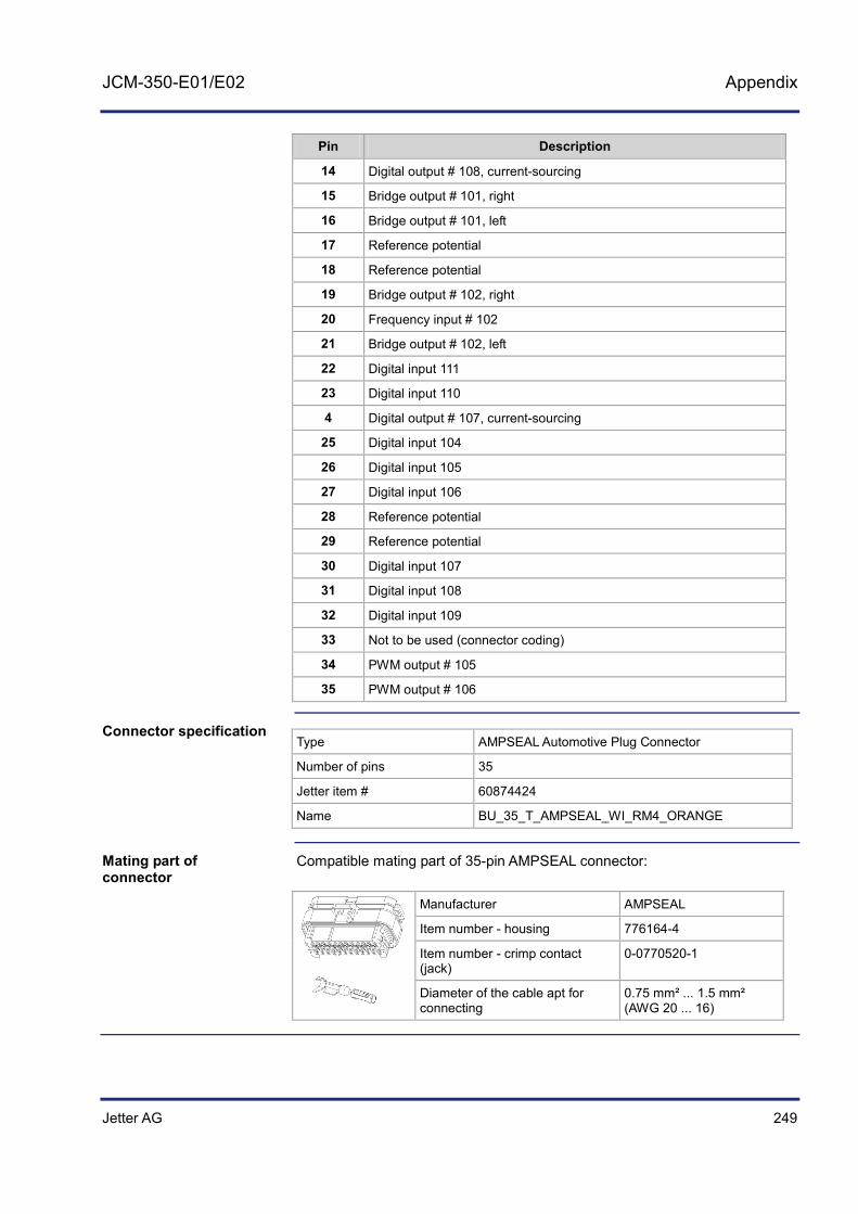
Jetter AG 249
JCM-350-E01/E02 Appendix
Pin Description
14 Digital output # 108, current-sourcing
15 Bridge output # 101, right
16 Bridge output # 101, left
17 Reference potential
18 Reference potential
19 Bridge output # 102, right
20 Frequency input # 102
21 Bridge output # 102, left
22 Digital input 111
23 Digital input 110
4 Digital output # 107, current-sourcing
25 Digital input 104
26 Digital input 105
27 Digital input 106
28 Reference potential
29 Reference potential
30 Digital input 107
31 Digital input 108
32 Digital input 109
33 Not to be used (connector coding)
34 PWM output # 105
35 PWM output # 106
Type AMPSEAL Automotive Plug Connector
Number of pins 35
Jetter item # 60874424
Name BU_35_T_AMPSEAL_WI_RM4_ORANGE
Compatible mating part of 35-pin AMPSEAL connector:
Manufacturer AMPSEAL
Item number - housing 776164-4
Item number - crimp contact (jack)
0-0770520-1
Diameter of the cable apt for connecting
0.75 mm² ... 1.5 mm² (AWG 20 ... 16)
Connector specification
Mating part of connector

250 Jetter AG
Appendix
Connector X119 - Pin assignment
The pin assignment of connectors X119 and X219 is the same. The signals going through the pins of these two connectors are functionally independent of each other and are not interconnected. There is no complete electrical isolation. Connector X119 features the following interfaces:
Analog inputs # 101 ... 104 Digital pull-down inputs # 101 ... 103 Digital outputs # 101 ... 104 CAN interfaces # 4 and 5 PWM outputs # 101 ... 104 Voltage supply for digital outputs # 101 ... 104 Voltage supply for digital inputs Voltage supply for analog inputs Voltage supply for PWM outputs
The diagram shows the pin assignment of connector X119:
1 12
13 23
24 35
X119
Pin Description
1 Analog input # 104
2 Analog input # 103
3 Digital input 103
4 Digital input 102
5 Digital input 101
6 Digital output # 102, current-sourcing
7 Digital output # 104, current-sourcing
8 Digital output # 101, current-sourcing
9 Digital output # 103, current-sourcing
10 Voltage supply for digital outputs # 101 ... 104
11 Voltage supply for digital outputs # 101 ... 104
Interfaces
Pin assignment

Jetter AG 251
JCM-350-E01/E02 Appendix
Pin Description
12 Voltage supply for electronic circuits
13 Analog input # 102
14 Analog input # 101
15 Analog output # 101
16 Analog output # 102
17 Reference potential
18 Reference potential
19 Voltage supply for analog outputs
20 Reference potential
21 Voltage supply for PWM outputs
22 Voltage supply for analog inputs
23 Voltage supply for digital inputs
24 PWM output # 101
25 PWM output # 102
26 PWM output # 103
27 PWM output # 104
28 Reference potential
29 Reference potential
30 CAN-L CAN interface # 5
31 Sensor power supply for analog peripheral devices
32 CAN-L CAN interface # 4
33 Do not connect
34 CAN-H CAN interface # 4
35 CAN-H CAN interface # 5
Type AMPSEAL Automotive Plug Connector
Number of pins 35
Jetter item # 60874423
Name BU_35_T_AMPSEAL_WI_RM4_SCHWARZ
Connector specification

252 Jetter AG
Appendix
Compatible mating part of 35-pin AMPSEAL connector:
Manufacturer AMPSEAL
Item number - housing 776164-4
Item number - crimp contact (jack)
0-0770520-1
Diameter of the cable apt for connecting
0.75 mm² ... 1.5 mm² (AWG 20 ... 16)
Mating part of connector

Jetter AG 253
JCM-350-E01/E02 Appendix
Connector X210 - Pin assignment
Only JCM-350-E02-xxx is equipped with connector X210. The pin assignment of connectors X110 and X210 is the same. The signals going through the pins of these two connectors are functionally independent of each other and are not interconnected. There is no complete electrical isolation. Connector X210 features the following interfaces:
Relay contacts # 201 ... 204 Analog outputs 203 ... 204 Frequency/pulse inputs # 202 ... 203 PWM outputs # 207 ... 208
The diagram shows the pin assignment of connector X210:
X210
1 8
9 15
16 23
Pin Description
1 Relay 201: common contact
2 Relay 202: NC contact
3 Relay 202: NO contact
4 Relay 202: common contact
5 Relay 203: common contact
6 Relay 203: NC contact
7 Relay 204: NC contact
8 Relay 203: NO contact
9 Relay 201: NO contact
10 Analog output # 203
11 Analog output # 204
12 PWM output # 207
13 PWM output # 208
Interfaces
Pin assignment

254 Jetter AG
Appendix
Pin Description
14 Relay 204: NO contact
15 Relay 204: common contact
16 Relay 201: NC contact
17 Reference potential
18 Power supply for external digital encoders short-circuit proof, thermal tripping
19 Frequency/pulse input 203
20 Frequency/pulse input 204
21 Unused
22 Unused
23 Unused
Type AMPSEAL Automotive Plug Connector
Number of pins 23
Jetter item # 60874422
Name BU_23_T_AMPSEAL_WI_RM4_SCHWARZ
Compatible mating part of 35-pin AMPSEAL connector:
Manufacturer AMPSEAL
Item number - housing 776164-4
Item number - crimp contact (jack)
0-0770520-1
Diameter of the cable apt for connecting
0.75 mm² ... 1.5 mm² (AWG 20 ... 16)
Connector specification
Mating part of connector

Jetter AG 255
JCM-350-E01/E02 Appendix
Connector X218 - Pin assignment
Only JCM-350-E02-xxx is equipped with connector X218. The pin assignment of connectors X118 and X218 is the same. The signals going through the pins of these two connectors are functionally independent of each other and are not interconnected. There is no complete electrical isolation. Connector X218 features the following interfaces:
Digital outputs # 205 ... 208 Voltage supply for digital outputs # 205 ... 208 Voltage supply for H-bridges # 201 ... 202 H-bridge outputs # 201 ... 202 Programmable digital active-high/active-low inputs # 204 ... 211 PWM outputs # 205 ... 206 Frequency Inputs 200 and 201
The diagram shows the pin assignment of connector X218:
X218
1 12
13 23
24 35
Pin Description
1 Digital output # 206, current-sourcing
2 Voltage supply for digital outputs # 205 ... 208
3 Voltage supply for digital outputs # 205 ... 208
4 Bridge output # 201, right
5 Bridge output # 201, left
6 Voltage supply for bridge # 201
7 Voltage supply for bridge # 201
8 Bridge output # 202, right
9 Bridge output # 202, left
10 Voltage supply for bridge # 202
11 Voltage supply for bridge # 202
Interfaces
Pin assignment

256 Jetter AG
Appendix
Pin Description
12 Frequency input # 201
13 Digital output # 205, current-sourcing
14 Digital output # 208, current-sourcing
15 Bridge output # 201, right
16 Bridge output # 201, left
17 Reference potential
18 Reference potential
19 Bridge output # 202, right
20 Frequency input # 202
21 Bridge output # 202, left
22 Digital input 211
23 Digital input 210
24 Digital output # 207, current-sourcing
25 Digital input 204
26 Digital input 205
27 Digital input 206
28 Reference potential
29 Reference potential
30 Digital input 207
31 Digital input 208
32 Digital input 209
33 Not to be used (connector coding)
34 PWM output # 205
35 PWM output # 206
Type AMPSEAL Automotive Plug Connector
Number of pins 35
Jetter item # 60874424
Name BU_35_T_AMPSEAL_WI_RM4_ORANGE
Connector specification

Jetter AG 257
JCM-350-E01/E02 Appendix
Compatible mating part of 35-pin AMPSEAL connector:
Manufacturer AMPSEAL
Item number - housing 776164-4
Item number - crimp contact (jack)
0-0770520-1
Diameter of the cable apt for connecting
0.75 mm² ... 1.5 mm² (AWG 20 ... 16)
Mating part of connector
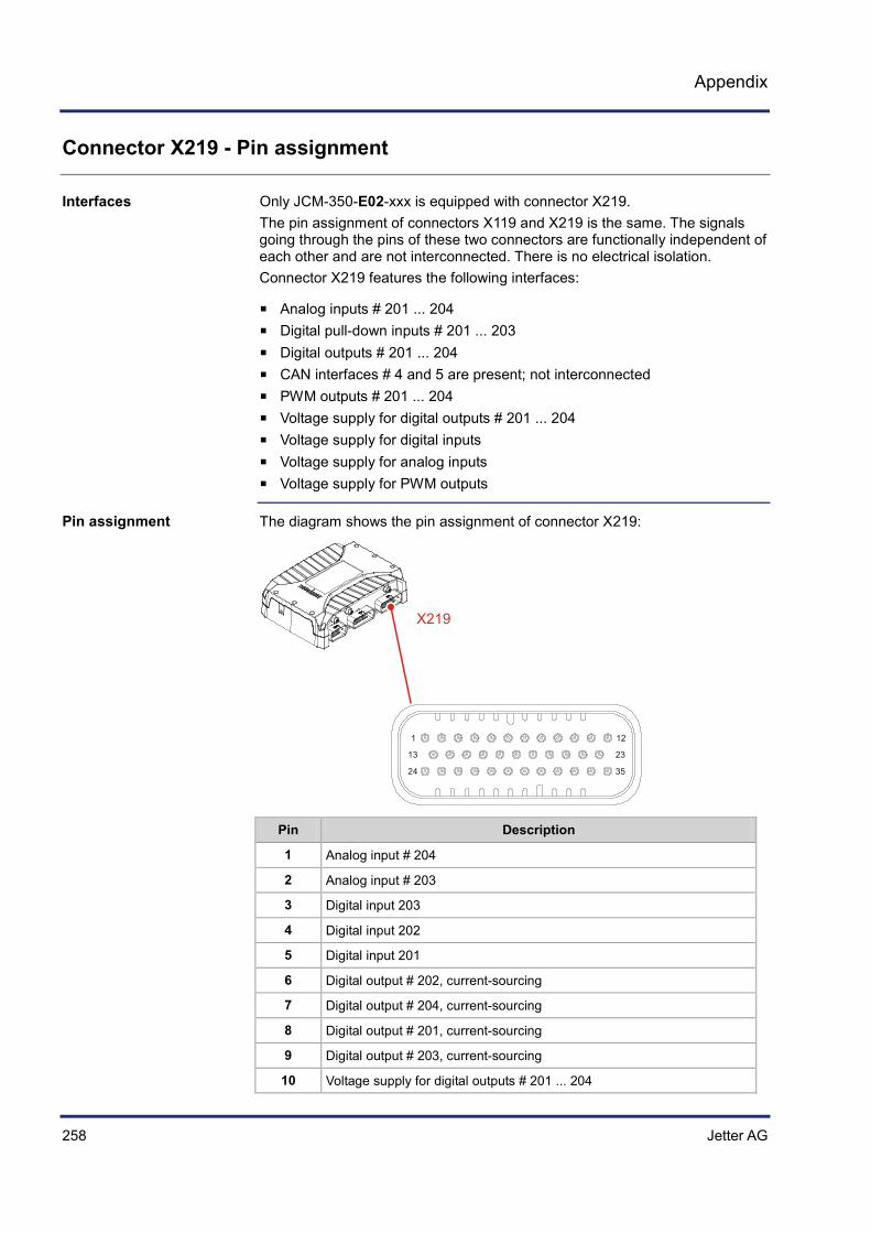
258 Jetter AG
Appendix
Connector X219 - Pin assignment
Only JCM-350-E02-xxx is equipped with connector X219. The pin assignment of connectors X119 and X219 is the same. The signals going through the pins of these two connectors are functionally independent of each other and are not interconnected. There is no electrical isolation. Connector X219 features the following interfaces:
Analog inputs # 201 ... 204 Digital pull-down inputs # 201 ... 203 Digital outputs # 201 ... 204 CAN interfaces # 4 and 5 are present; not interconnected PWM outputs # 201 ... 204 Voltage supply for digital outputs # 201 ... 204 Voltage supply for digital inputs Voltage supply for analog inputs Voltage supply for PWM outputs
The diagram shows the pin assignment of connector X219:
X219
1 12
13 23
24 35
Pin Description
1 Analog input # 204
2 Analog input # 203
3 Digital input 203
4 Digital input 202
5 Digital input 201
6 Digital output # 202, current-sourcing
7 Digital output # 204, current-sourcing
8 Digital output # 201, current-sourcing
9 Digital output # 203, current-sourcing
10 Voltage supply for digital outputs # 201 ... 204
Interfaces
Pin assignment

Jetter AG 259
JCM-350-E01/E02 Appendix
Pin Description
11 Voltage supply for digital outputs # 201 ... 204
12 Voltage supply for electronic circuits
13 Analog input # 202
14 Analog input # 201
15 Analog output # 201
16 Analog output # 202
17 Reference potential
18 Reference potential
19 Voltage supply for analog outputs
20 Reference potential
21 Voltage supply for PWM outputs
22 Voltage supply for analog inputs
23 Voltage supply for digital inputs
24 PWM output # 201
25 PWM output # 202
26 PWM output # 203
27 PWM output # 204
28 Reference potential
29 Reference potential
30 Not interconnected
31 Sensor power supply for analog peripheral devices
32 Not interconnected
33 Do not connect
34 Not interconnected
35 Not interconnected
Type AMPSEAL Automotive Plug Connector
Number of pins 35
Jetter item # 60874423
Name BU_35_T_AMPSEAL_WI_RM4_SCHWARZ
Connector specification

260 Jetter AG
Appendix
Compatible mating part of 35-pin AMPSEAL connector:
Manufacturer AMPSEAL
Item number - housing 776164-4
Item number - crimp contact (jack)
0-0770520-1
Diameter of the cable apt for connecting
0.75 mm² ... 1.5 mm² (AWG 20 ... 16)
Mating part of connector

Jetter AG 261
JCM-350-E01/E02 Appendix
B: Technical Data
This section of the appendix contains both electrical and mechanical data, as well as operating data of the JCM-350-E01/E02 module.
Topic Page Technical specifications .............................................................................. 262 Physical dimensions ................................................................................... 268 Operating parameters - Environment and mechanics ................................ 270 Operating Parameters - EMC ..................................................................... 271
Introduction
Contents

262 Jetter AG
Appendix
Technical specifications
Parameter Description
Configurable output voltage range DC 0 V ... DC 10 V, maximum supply voltage for analog outputs DC 0 V ... DC 32 V, maximum supply voltage for analog outputs
Maximum output current 100 mA
Accuracy related to ultimate voltage value 99 %
Parameter Description
Maximum input voltage for voltage measurements
+32 V
Maximum input current for current measurements
22.5 mA (+9 V)
Resolution 12 bits
Accuracy 99.5 %
Input frequency 50 Hz
Limit frequency of 10 V range 250 Hz, 3 dB attenuation of input signal, Input impedance: 43 kΩ
Limit frequency of 32 V range 660 Hz, 3 dB attenuation of input signal, Input impedance: 35 kΩ
Input impedance (voltage) 35 kΩ / 43 kΩ
Input impedance (current) 400 Ω
Analog inputs - Technical specifications
Analog inputs - Technical specifications

Jetter AG 263
JCM-350-E01/E02 Appendix
Parameter Description
Maximum rated current per output 8 A
Total current for outputs 101 ... 104 16 A
Total current for outputs 105 ... 108 16 A
Total current for outputs 201 ... 204 16 A
Total current for outputs 205 ... 208 16 A
Switching frequency 100 Hz
Allowed overload current per output during power-up
40 A for 500 ms
Allowed overload current per output during power-up
16 A for 4 s
Minimum voltage per output; dependent on the supply voltage for digital outputs
7.0 V
Maximum voltage per output; dependent on the supply voltage for digital outputs
32 V
Parameter Description
Type of inputs Active-high or active-low input (programmable)
Permissible voltage range DC 7.5 V ... DC 32 V
Typical threshold level OFF Active-high: < 0.3 x supply voltage of digital inputs Active-low: > 0.7 x supply voltage of digital inputs
Typical threshold level ON Active-high: > 0.7 x supply voltage of digital inputs Active-low: < 0.3 x supply voltage of digital inputs
Typical input resistance 3.2 kΩ
Typical input current (U = 24 V) 7.5 mA
Maximum input frequency 50 Hz
Digital outputs - Technical specifications
Digital Inputs - Technical Data

264 Jetter AG
Appendix
Parameter Description
Type of inputs Active-low inputs with pull-down resistor
Permissible voltage range DC 0 V ... DC 32 V
Threshold level OFF < 0.3 x supply voltage of digital inputs for JCM-350-Exx-G05
< 0.2 x supply voltage of digital inputs for JCM-350-Exx-G12
Threshold level ON > 0.7 x supply voltage of digital inputs for JCM-350-Exx-G05
> 0.3 x supply voltage of digital inputs for JCM-350-Exx-G12
Typical input resistance 3.2 kΩ
Typical input current 7.5 mA
Maximum input frequency 50 kHz
Parameter Description
Voltage supply of outputs 0.3 V
Overload behavior 80 A for 500 ms 32 A for 4 s
Current measurement, resolution 12 bits
Accuracy related to twice the rated current 95 %
Switching frequency (1/period length) 100 Hz ... 4 kHz
Frequency accuracy 100 ppm
Resolution of pulse control factor 20 ns
Parameter Description
Relay type 101, 102, 201, 202 Minirelais K (Infineon)
Contact 1 x UM
Permissible voltage range DC 5 V ... DC 32 V
Permissible current 0.5 A ... 15 A
Parameter Description
Relay type 103, 104, 203, 204 Cp1 Relay (Nais)
Contact 1 x UM
Permissible voltage range DC 5 V ... DC 32 V
Permissible current 0.5 A ... 2 A
In the case of inductive loads, install an appropriate contact protection (free-wheeling diode, spark suppressor).
Frequency/pulse inputs - Technical specifications
H-bridges 1/2 - Technical specifications
High-current relay - Technical specifications
Standard relay - Technical specifications
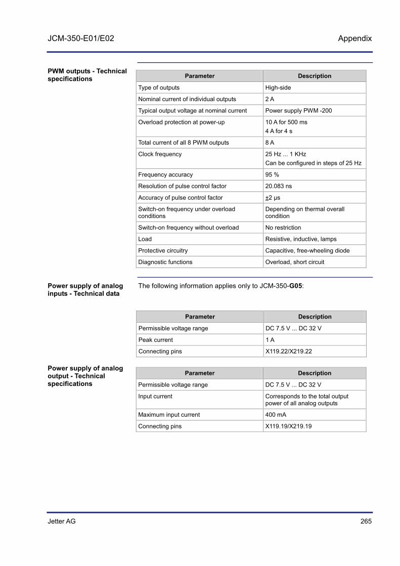
Jetter AG 265
JCM-350-E01/E02 Appendix
Parameter Description
Type of outputs High-side
Nominal current of individual outputs 2 A
Typical output voltage at nominal current Power supply PWM -200
Overload protection at power-up 10 A for 500 ms 4 A for 4 s
Total current of all 8 PWM outputs 8 A
Clock frequency 25 Hz ... 1 KHz Can be configured in steps of 25 Hz
Frequency accuracy 95 %
Resolution of pulse control factor 20.083 ns
Accuracy of pulse control factor ±2 µs
Switch-on frequency under overload conditions
Depending on thermal overall condition
Switch-on frequency without overload No restriction
Load Resistive, inductive, lamps
Protective circuitry Capacitive, free-wheeling diode
Diagnostic functions Overload, short circuit
The following information applies only to JCM-350-G05:
Parameter Description
Permissible voltage range DC 7.5 V ... DC 32 V
Peak current 1 A
Connecting pins X119.22/X219.22
Parameter Description
Permissible voltage range DC 7.5 V ... DC 32 V
Input current Corresponds to the total output power of all analog outputs
Maximum input current 400 mA
Connecting pins X119.19/X219.19
PWM outputs - Technical specifications
Power supply of analog inputs - Technical data
Power supply of analog output - Technical specifications

266 Jetter AG
Appendix
Parameter Description
Permissible voltage range DC 7.5 V ... DC 32 V
Input current Total output current - H-bridge 1
Maximum output current 16 A
Connecting pins X118.6, X118.7/ X218.6, X218.7
Parameter Description
Permissible voltage range DC 7.5 V ... DC 32 V
Input current (at 24 V power supply) 150 mA
Connecting pins X119.23/X219.23
Parameter Description
Permissible voltage range DC 7.5 V ... DC 32 V
Current consumption Sum of output currents of digital outputs 1 ... 4
Connecting pins X119.10, X119.11/ X219.10, X219.11
Parameter Description
Permissible voltage range DC 7.5 V ... DC 32 V
Current consumption Sum of output currents of digital outputs 5 ... 8
Connecting pins X118.2, X118.3/ X218.2, X218.3
Parameter Description
Permissible voltage range DC 7.5 V ... DC 32 V
Input current (at PWM power supply = 24 V)
Corresponds to the total output power of all PWM outputs
Maximum total output current of all PWM outputs
8 A
Connecting pins X119.21/X219.21
Power supply of H-bridge 1 - Technical specifications
Power supply of digital inputs - Technical specifications
Power supply of digital outputs 1 ... 4 - Technical specifications
Power supply of digital outputs 5 ... 8 - Technical specifications
Power supply of PWM outputs - Technical specifications

Jetter AG 267
JCM-350-E01/E02 Appendix
Parameter Description
Operating voltage - device DC 7 V ... 32 V
Operating voltage - controller ≥ DC 5.5 V
Typical input current (at 24 V power supply) 200 mA + encoder supply (only for G12 models)
Connecting pins X119.12/X219.12
Parameter Description
Flash 16 MB
SDRAM 16 MB
FRAM (remanent) 32 kB
Parameter Description
Baud rates 250 kBaud
Bus termination None
External termination recommended 120 Ω
Power supply UC_UBAT - Technical specifications
Memory - Technical Data
CAN interface - Technical specifications
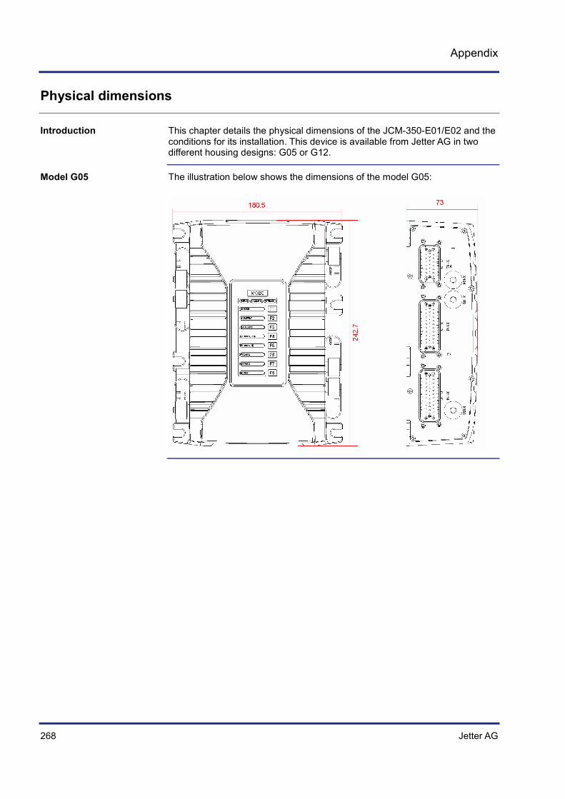
268 Jetter AG
Appendix
Physical dimensions
This chapter details the physical dimensions of the JCM-350-E01/E02 and the conditions for its installation. This device is available from Jetter AG in two different housing designs: G05 or G12.
The illustration below shows the dimensions of the model G05:
Introduction
Model G05

Jetter AG 269
JCM-350-E01/E02 Appendix
The illustration below shows the dimensions of the model G12:
When you select a place for installing the JCM-350-E01/E02, consider the following facts:
The JCM-350-E01/E02 increases the temperature of the environment as a result of heat emission under load.
The JCM-350-E01/E02 design enables excess heat to be dissipated via base plate. Ensure an unobstructed heat conduction.
Consider the heat emission from the JCM-350-E01/E02, in particular when installing it in a critical environment:
In the vicinity of the fuel tank In the vicinity of the fuel pipe In the vicinity of flammable vehicle components In the vicinity of thermally malleable vehicle components
When you select a place for installing the JCM-350-E01/E02, consider the following facts:
Ensure there is enough space around the connector for servicing requirements. It should be possible to disconnect the connector at any time.
Ensure there is enough space around the operator interface for servicing requirements. The operator interface must be visible and accessible.
Model G12
Protection against overheating
Space required for installation and service
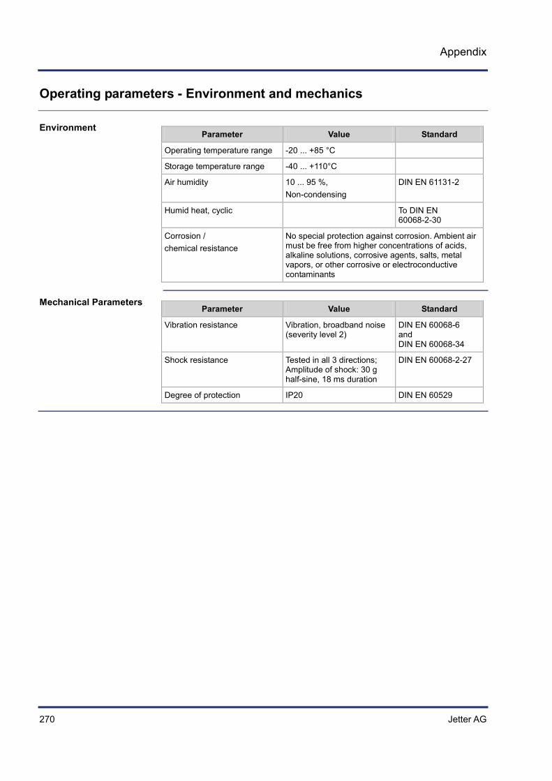
270 Jetter AG
Appendix
Operating parameters - Environment and mechanics
Parameter Value Standard
Operating temperature range -20 ... +85 °C
Storage temperature range -40 ... +110°C
Air humidity 10 ... 95 %, Non-condensing
DIN EN 61131-2
Humid heat, cyclic To DIN EN 60068-2-30
Corrosion / chemical resistance
No special protection against corrosion. Ambient air must be free from higher concentrations of acids, alkaline solutions, corrosive agents, salts, metal vapors, or other corrosive or electroconductive contaminants
Parameter Value Standard
Vibration resistance Vibration, broadband noise (severity level 2)
DIN EN 60068-6 and DIN EN 60068-34
Shock resistance Tested in all 3 directions; Amplitude of shock: 30 g half-sine, 18 ms duration
DIN EN 60068-2-27
Degree of protection IP20 DIN EN 60529
Environment
Mechanical Parameters

Jetter AG 271
JCM-350-E01/E02 Appendix
Operating Parameters - EMC
This device has been checked as per Directive 72/245/EEC with all amendments up to 2009/19/EC and meets all test criteria.
Parameter Value Standard
Emitted interference Requirements of Appendix 6 and 7 are met
Directive 72/245/EEC with all amendments including 2009/19/EC
Anechoic chamber / electromagnetic fields
Fulfilled ISO 11452-2
Parameter Value Standard
Interference immunity to conducted faults
Fulfilled Directive 72/245/EEC with all amendments including 2009/19/EC
Interference immunity to external magnetic field
20 ... 2,000 MHz: Irradiation up to 100 V/m
Directive 72/245/EEC with all amendments including 2009/19/EC
Electrostatical Discharge Severity level 2 ISO 10605
Electromagnetic disturbance caused by power and coupling
Type of test pulses: 1, 2a, 2b, 3a, 3b, 4
ISO 7637-2
Anechoic chamber / electromagnetic fields
Fulfilled ISO 11452-2
Load dump Pulse 5b 120 V with 4 Ω ISO 7637-2
EMC - Emitted interference
EMC - immunity to interference

272 Jetter AG
Index
C: Index
A A/D conversion - 223
Configuring several measuring ranges - 225 Processing analog voltages - 224
C CANopen® objects - 99
PDO parameters - 116, 123 SDO parameters - 106, 111
CANopen® STX API - 99 Components of the JCM-350-E01/E02 - 19 Connecting and wiring - 47 Connector specification - 51, 53
D D/A conversion - 229, 230 Diagnostic feature - 82 Digital outputs - 70
E EDS registers
Controller 350 - 29 I/O Module - 31
Electrical connection - 16, 19 Enabling the I/O module - 98 Example of wiring layout - 48
I I²t monitoring - 81 Identification - 31, 33, 37 Initial commissioning - 90, 98 Installation - 41 Interfaces - 19, 245
CAN - 63 Operator panel - 16 Pin assignment of connectors - 58, 245
M Maintenance - 14
N Nameplate - 26, 27
O Operating parameters - 262
EMC - 271 Environment and mechanics - 270
Operator panel - 16 Order reference - 22
P Physical dimensions - 23 Pin assignment of connectors - 58, 245
Connector X110 - 246 Connector X118 - 248 Connector X119 - 250 Connector X210 - 253 Connector X218 - 255 Connector X219 - 258
Power supply - 50, 51, 53 Product description - 15, 19 Product models - 16, 22 Programming - 168
Analog - 222, 223, 229 Relay - 214
Digital Digital I/Os - 187, 194, 201 Frequency measurement - 204 H-bridge - 216 Operator panel - 176 PWM - 210 Relay - 214
Protective features - 82
Q Quick reference - 241
R Residual Dangers - 14
S SAE J1939 STX API - 139 Safety Instructions
Residual Dangers - 14 Software version - 31, 37
T Technical Specifications - 23, 262


274 Jetter AG
Jetter AG
Graeterstrasse 2
D-71642 Ludwigsburg
Germany
Phone: +49 7141 2550-0
Phone - Sales:
+49 7141 2550-433
Fax - Sales:
+49 7141 2550-484
Hotline: +49 7141 2550-444
Internet: http://www.jetter.de
E-Mail: [email protected]
Jetter Subsidiaries
Jetter (Switzerland) AG Jetter Automation Technology (Shanghai) Co., Ltd.
Jetter USA Inc.
Wilerstr. 15 NO.49, Lane 2927, Lai Yang Road, 13075 US Highway 19 North
CH-9602 Bazenheid Pudong New District Florida - 33764 Clearwater
CN-200137 Shanghai
Switzerland China U.S.A
Phone: +41 71 91879-50 Phone: +86 215 869-1233 Phone: +1 727 532-8510
Fax: +41 71 91879-59 Fax: - Fax: +1 727 532-8507
E-Mail: [email protected] E-Mail: [email protected] E-Mail: [email protected]
Internet: http://www.jetterag.ch Internet: http://www.jetterat.cn Internet: http://www.jetter.de


