Copyright 2009 Outpost Enterprises LTD Page 2 The world’s largest catalog of quality model stirling engines, atmospheric engine, gas engine, and other model engineering projects. Also hard-to-find part sets, transistor ignition system kits, bearings, complete Boehm Engine Kits, and other supply items for the hobby, educational and experimental engine Machinist. All plans sets are bar stock projects with no castings required. This is the lowest cost way for you to build these projects as the material can usually be purchased from salvage yards at very attractive prices. However, most of the engines are designed to look like they were in fact built from castings instead of rectangular blocks of metal! All plans are high quality computer generated and printed on 8 1/2 x 11” sheets with a laser printer. This permits you to make workshop copies that are sure to get soiled, and you can keep the originals like new or put originals in plastic sheet protectors to use. Dimensions are in U.S. inch decimals—no fractions—which makes it easy for you to change the scale of your model to suit your machine tool capacity or the materials you have on hand or have access to. The prototype models are thoroughly tested, improvements made where possible, and were re-tested until satisfied. Then the model were disassembled for precise measuring of each part to create the plans you get. This assures that the plans exactly represent the prototype model at the final stage of development. There are more tips, pictures and a wealth of information on the website as well as other products and surplus items & tools you may not see included in this catalog. www.model-engine-plans.com JE Howell Model Engine Plans Operated & Owned by Outpost Enterprises, LTD 695 Godfrey Road Hollansburg OH 45332 [email protected]
Transcript
Copyright 2009 Outpost Enterprises LTD
Page 2
The world’s largest catalog of quality model stirling engines, atmospheric engine, gas engine, and other model engineering projects. Also hard-to-find part sets, transistor ignition system kits, bearings, complete Boehm Engine Kits, and other supply items for
the hobby, educational and experimental engine Machinist.
All plans sets are bar stock projects with no castings required. This is the lowest cost way for you to build these projects as the material can usually be purchased from salvage yards at very attractive prices. However, most of the engines are designed to look like they were in fact built from castings instead of rectangular blocks of metal!
All plans are high quality computer generated and printed on 8 1/2 x 11” sheets with a laser printer. This permits you to make workshop copies that are sure to get soiled, and you can keep the originals like new or put originals in plastic sheet protectors to use.
Dimensions are in U.S. inch decimals—no fractions—which makes it easy for you to change the scale of your model to suit your machine tool capacity or the materials you have on hand or have access to.
The prototype models are thoroughly tested, improvements made where possible, and were re-tested until satisfied. Then the model were disassembled for precise measuring of each part to create the plans you get. This assures that the plans exactly represent the prototype model at the final stage of development.
There are more tips, pictures and a wealth of information on the website as well as other products and surplus items & tools you may not see included in this catalog.
This modified Heinrici stirling cycle engine doesn’t need a fire to operate it. It has
no valves, ignition system, carburetor, or exhaust. It will run on any of heat source such as on top of a cup of warm water (coffee), from the TV, VCR, and a zillion other sources. It runs on as about 90 RPM when held in the palm of a hand and
much faster with the other heat sources. It will also operate in reverse from a cold
source such as ice or snow. As can be seen, the possibilities are almost endless.
Folks who are not ordinarily interested in engines of any kind are always curious about this one. Unlike other low temperature engines, I designed Miser to actually
look like an engine! Isn’t that a novel idea! It is not as hard to build as it may look,
but you can simplify the styling if you are in a hurry to get yours running.
Miser is built mostly from aluminum alloy bar stock and plate, while most of the
smaller parts are of brass or steel. A few parts that can’t be metal because they need to be good heat insulators are made from clear acrylic (so the works can be
seen) or delrin.
The plans set: consists of 10 sheets of quality laser printed CAD drawings and 2
sheets of construction and assembly notes.
Materials Set: (1) Graphite rod to make piston (2) 5/32" ID x 5/16" OD x 1/8" thick,
flanged precision ball bearings. Materials Kit sold separately.
Miser Engine Plans Item ID: Miser-P
Miser Materials Set Item ID: Miser-Set
Miser Displacer Ring Item ID: Miser-Ring
1/2 Size “Mini Miser” Parts Set Item ID: 1/2 Miser-Kit
*** See separate pricing sheet for all prices in this catalog ***
"Your Miser engine looks good, not like some half finished scientific experiment." -
Mal Horsfall (Quakers Hill, NSW Australia)
The Miser engine type is the best conversation piece
ever invented. It will run on a cup of warm coffee, the
warmth of your hand, or even an ice cream cone! Here is an engine that you can actually operate in bed
with no danger of setting the sheets on fire!
Vickie Victorian Stirling
Cycle Engine
Page 6
Specifications
Flywheel Dia.: 4 5/8” Cylinder Bore: .600”
Piston Stroke: 1” Overall Length: 10”
Experience Level: 8
Stirling engines have no valves, carburetor, ignition system or boilers and they run
almost ghostly silent. Properly made, they will run flawlessly every time a source of
heat is applied!
“Vickie” is a stirling cycle engine of modified Heinrici type with elegant Victorian styling designed for pleasing looks as was applied to 18th and 19th century
engines and machines. Three fluted columnar legs and two stylish crossheads of differing style blend perfectly with the curved and angular lines of the engine
frames.
The engine is primarily made of aluminum with accents of polished brass and stainless steel and trimmed in dark green & maroon paint. A belt brass cooling fan competes with the rod and crosshead action for attention. Vicki is powered by an
attractive horizontal brass alcohol burner which sports an integral fuel level sight
glass.
Vicki is considered by many to be one of the most beautiful stirling engines ever designed. I hope that you’ll agree too! She is a true heirloom engine which will
surely be handed down from generation to generation.
The plans set: consists of 16 sheets of drawing and 3 sheets of construction and
assembly notes.
Materials Set: (1) 5/8" dia. x 1.4" long graphite for piston (2) .250" x .500" x .187"
thick ball bearings. Materials Kit sold separately.
Vickie Engine Plans Item ID: Vickie-P
Vickie Materials Set Item ID: Vickie-Set
"Thanks for the quick return of the plans I ordered, now I intend to make a small
family of your designs........ The local model engineering club is well acquainted with your work and were very impressed with the "Vickie", the first of your engines I
have built." - John L. Saunders, Shoreham-by-Sea (West Sussex, England)
Beamer represents a large Victorian style beam engine that could have existed in the mid to late 1800’s. It is an unique design and noting lik eit has ever been done before. A belt driven cooling fan allows the engine to operate continuously at a temperature only slightly above ambient! All shafts are fitted with ball bearings for a smooth running and maintenance free engine. An operating flyball governor which is driven by the fan belt adds much interest to the engine, but it doesn’t regulate the engine speed. The engine runs at a nice leisurely pace from a 1/4” dia. X 5/16” tall flame of an alcohol lamp, or one of my mini propane burners.
The plans set: consists of 15 sheets of drawings & 2 sheets of construction notes.
Materials Set: (1) 5/8" dia. x 2" long graphite rod for piston (2) .250" x .500" x .187" ball bearings (2) .187" x .375" flanged bearings (4) .156" x .312" flanged bearings (1) 1/2" dia. x 1-1/2" long delrin rod (1) 1/4" dia. x 1-1/2" long delrin rod. Materials
Kit sold separately.
Beamer Engine Plans Item ID: Beamer-P
Beamer Materials Set Item ID: Beamer-Set
"Just thought I'd let you know I received the Beamer plans & kit. As usual they are
very nice." - Chris Anthony (Howard, Ohio)
Page 8
Duplex Vacuum Stirling
Cycle Engine
This engine is not a “vacuum” engine, it is a “beta” type stirling engine. Beta means that the power piston and the displacer are both working in the same cylinder. This arrangement gives greater power output than the typical two cylinder engine. The reason for this is that the compression ratio can be higher due to less “dead” space inside the engine.
The Duplex Vacuum Company of Chicago, Illinois made this type of engine about 100 years ago. They were widely used in popcorn wagons and to operate dental drills among other applications due to their silent operation and reliability.
A unique feature of the Duplex engines is the oscillating shaft and linkage which produces an interesting motion in operating the displacer.
The plans set: consists of 8 sheets of drawings and 2 sheets of construction and
assembly notes.
Materials Set: (1) Graphite rod to make piston (2) 3/16" ID x 3/8" OD x 1/8" thick
precision ball bearings. Materials Kit sold separately.
Duplex Engine Plans Item ID: Duplex-P
Duplex Materials Set Item ID: Duplex-Set
"I would like to thank you for all your years of coming to the PRIME Exhibition, you were always one of the most popular builders and your work is so beautiful." - Ram
The Ringbom stirling cycle engine is unique in that there is no mechanical connection to the displacer. The displacer operates itself from the pulsating pressure variations within the engine. The engine has only four moving parts.
The engine makes a distinctive thumping sound like no other engine and runs at a fairly constant speed of around 700 RPM when powered by my Mini Propane burner which is highly recommended. This is a water cooled model and the plans also include an engine driven oscillating water pump that has only three moving parts and no check valves! It is your choice to build the pump or to supple cooling water to the engine by other means.
Ringbom engines and the plans are very rare but now you can build a Ringbom engine of your own!
The plans set: consists of 11 sheets of drawings & 2 sheets of construction and
assembly notes.
Materials Set: (1) 5/8" dia. x 1.9" long graphite for piston (2) .156" x .312" flanged
bearings. Materials Kit sold separately.
Ringbom Engine Plans Item ID: Ringbom-P
Ringbom Materials Set Item ID: Ringbom-Set
"Thanks for ALL that you contribute to the model engine world and the machining
hobby in general with your great plans and designs." - John Guenther (Sterling, Virginia)
4-in-1 Vacuum Engine
Specifications
Flywheel Diameter: 4” Cylinder Bore: 1”
Piston Stroke: 1 3/8” Overall Length: 9”
Experience Level: 3
Page 10
The correct terminology is “atmospheric engine”. But anyway, here is a “flame
eater” engine you can build any of four ways: (1) Air Cooled Side Crank as shown, (2) Water Cooled Side Crank, (3) Air Cooled Center Crank or (4) Water Cooled
Center Crank!
The cooled engines have an optional belt driven cooling fan which provides cooling
for long running sessions. The engine runs fine without it. With the fan, the engine will run all day long and never get hot. But long runs or not, the fan also adds much interest to the engine. All four versions use my oscillating (twisting) side shaft
mechanism to operate the head valve. My unique valve seat is of self lubricating non-metallic material which greatly reduces valve sliding friction and virtually
eliminates wear. The engine speed range is from 60 to 600 RPM or so.
Then engine can be ran on an alcohol flame, but for easy and accurate speed
control, use my Mini Propane Burner.
The plans set: consists of 19 sheets of drawings & 2 sheets of construction and assembly notes.
Materials Set: (1) 1.045" dia. x 1.5" long graphite for piston. (2) .250" x .500" x .187" thick ball bearings. (3) .156" x .312" flanged ball bearings for fan hub and connecting rod end. Materials Kit sold separately.
4 in 1 Vacuum Engine Plans Item ID: 4in1-P
4 in 1 Vacuum Materials Set Item ID: 4in1-Set
"All I can say is WOW! I can now truly appreciate why everyone who has bought
your model plans speaks so highly of you!" - Robert Schenk (San Francisco, CA)
These are also known by some as “Fire Eaters” or “Flame Suckers” but
technically, they are “Atmospheric” engines.
My unique valve mechanism operates from an oscillating side shaft. The engine is shown powered by one of my Mini Propane Burners (a separate plans set) at the front of the engine. You can run yours with an alcohol lamp if you like. A belt driven
fan provides some air cooling, it also adds considerable interest to the engine. There is no ignition or carburetor to cause problems. The engine can operate from 200 RPM up to 3,000 RPM or more! As hot-air engines—not stirling cycle— they
are unusual in that they make a popping sound not unlike an internal combustion
engine.
I built this engine 25 years ago. It is easy to build, but it is small and has some
small parts in it. For a larger refined “atmospheric” engine, see the “4-in-1” Vacuum
Engine on page 10.
The plans set: consists of 4 sheets of drawings and I sheet of construction and
assembly notes.
Materials Set: (1) Graphite rod to make piston, (2) 3/16" ID x 3/8" OD x 1/8" thick
precision ball bearings. Materials Kit sold separately.
Sideshaft Engine Plans Item ID: Sideshaft-P
Sideshaft Materials Item ID: Sideshaft-Set
"Thanks for the great tips on your web site. I have ordered plans from you in the past, great quality, prices more than reasonable. Keep up the good work." - Mike
In the late 1800’s and the early decades of the 1900’s fans of this type were used the world over in areas where there was no electricity.
This model has a 5 1/4” diameter fan powered by a miniature modified Heinrici stirling cycle engine. This is one project that has practical value! The fan runs at about 900 RPM and blows a nice breeze considering it’s small size. The fan is cute in this small size, but if you want to move more air you ought to check out the “Super Stirling Cycle Engine Fan” on the next page.
I made the alcohol lamp from an old coffee creamer jar that was once used in restaurants. It powers the fan for nearly two hours. The wick is a cotton “pipe stem cleaner”.
The plans set: consists of 5 sheets of drawings and 2 sheets of construction
notes.
Materials Set: (1) Graphite rod to make piston (2) 5/32" ID x 5/16" OD x 1/8" thick
flanged precision ball bearings. Materials Kit sold separately.
Mini Fan Engine Plans Item ID: Minifan-P
Mini Fan Materials Set Item ID: Minifan-Set
"I am VERY pleased with your service and the quality and value of your products." -
Rene Inman (Wigam, Lancashire, United Kingdom)
"Your drawings are art. Just gorgeous!" - Sylvan Heumann (Hillsboro, California)
Super Stirling Engine Fan
This fan was designed to be a real workhorse. Every effort was made to reduce
friction to an absolute minimum while at the same time making the unit extremely reliable, maintenance free, quiet and very long lived. My fan has many hundreds of running hours on it while at shows and in my office during summer months with no
maintenance, service or repairs of any kind done, or needed.
In addition to the crankshaft running in ball bearings, the power piston rod is fitted with precision ball bearings. All of the reciprocating parts use very low friction non-metallic components and never need oiled. The hot cap is specially designed to
absorb heat from the flame. The carefully shaped and angled concave fan blades
improve the overall air moving efficiency.
The fan operated nicely on an alcohol flame only 1/4” diameter and 5/16” tall,
moving a very respectable amount of air. During a day long run, the displacer cylinder will never get more than just luke warm. One other design consideration
was to make the fan an attractive piece of machinery. You will be the judge of that!
The plans set: consists of 9 sheets of drawings and 2 sheets of construction and
assembly notes.
Materials Set: (1) 5/8" dia. x 1.9" long graphite rod for piston, (2) .187" x .375" flanged bearings, (1) .156" x .312" flanged bearing, (1) 3/8" dia. x 2-1/4" long delrin
rod, (4) 1/16" x 1/2" roll pins. Materials Kit sold separately.
Super Fan Engine Plans Item ID: Superfan-P
Super Fan Materials Set Item ID: Superfan-Set
"Your designs are always 'the best'." - Ron Colonna (McKeesport, Pennsylvania)
Flywheel Diameter: 3" Height on Skid: 7.07" Overall Width: 5.75"
Length w/Radiator: 7.6" Experience Level: 5
The engine plans include everything in this photo except the stainless steel
exhaust pipes. The engine is 1.95 Cu. In. (32ccin displacement. Cylinders are 90 degrees apart in order to have the engine balanced for vibration free running. The cylinder bore is .875" and the piston stroke is .812". The cylinder banks are not
staggered and robust knife and fork connecting rods are used. The multi segment built-up crankshaft and twin cam shafts are amazingly easy to make. A Hall Effect distributor is driven off the end of one of the cam shafts. The distributor body is
linked to the throttle arm for spark advance/retard with the throttle setting. The throttle is my newest proven 2-jet design with an oiled foam air cleaner. Pressure lubrication to the rod ends is by an external gear oil pump which feeds oil through
the drilled crankshaft. There is an oil pressure adjuster and an oil pressure gauge port. The engine is water cooled using my unique magnetic drive water pump which has no seals to leak, and a proper looking and effective shop made radiator.
The fan blade shroud insures that the 5 curved blade fan actually pulls air through the radiator fins and not just circulate the air around behind the radiator as would otherwise result without one. There are ball bearings on the crankshaft, timing
gears, camshaft, distributor, rocker arms, water pump, oil pump and fan shaft. All external parts are sealed using "O" rings which prevent any oil seepage from the engine. A crankcase vent/check valve maintains negative crankcase pressure. A
dipstick is provided to monitor the oil level and also an easy to get to oil drain plug. Checking the RPM with a Laser Digital Tachometer on initial test runs show an idle speed of approximately 1,000 RPM and a top speed of 6,500+ RPM. Both of these
are expected to improve after the engine is fully broken-in.
The plans set: consists of 65 detailed sheets of quality laser printed CAD drawings
and 5 sheets of Construction Notes. Every feature of the engine as shown is
included in the plans set including 2-Jet Throttle, Air Cleaner, Water Pump, Oil
Pump, Hall Effect Distributor, Radiator, Skid, Etc. EXCEPT the stainless steel
exhaust pipes and manifolds. A full-size drawing of the manifolds is included but
does not contain dimensions. A new page with manifold dimensions is pending,
however, we have no estimated completion date.
Howell V4 Engine Plans Item ID: V4-P *more items available on price sheet*
The Howell V-Four is the Sherline Craftsmanship Museum Group Build
*see separate order page for more information and additional items available*
"I built the 'Howell' V-Twin' last year. Runs great!! Fabulous engine!!" - Jim Billings
(Fort Worth, Texas)
Page 18
Advertised by the Downing Engine Works of Des Plains, Illinois in 1906 for $125.00, the 3 horsepower "Bill" engine is somewhat of an enigma. A patent was issued to William A. Downing for the design but it is not known how many were actually produced, if any. The very simple and attractive engine was probably intended for light duty work such as pumping water, powering a grinding wheel or a small dynamo, etc. A listing for the "Bill" can be found on page 141 of American Gasoline Engines Since 1872 by C.H. Wendel. This is an approximate 1/3 scale model of the 1906 "Bill" engine. It runs on propane gas. On liquid fuel, due to the remoteness from the engine, the mixer soon gets cold from liquid fuel vaporization and after that the fuel doesn't vaporize very well which results in ragged operation. A propane demand valve was made for it and running on propane solves that problem. I have to presume that the prototype engine encountered the same problems (it may have ran on illuminating gas), but there was no propane to the rescue back in those days! Engine operation on propane is a big plus. Valves and spark plug stay very clean and there is no smelly exhaust! I have been changing the crankcase oil every 10 running hours since break-in but it still looks new, so I am going to extend it to 20 hours. This wouldn't be the case using a liquid fuel. "Bill" is machined and fabricated primarily of brass bar stock. The only castings used are the pipe elbows. The crankshaft runs on ball bearings, the cylinder has a cast iron liner and the piston is aluminum alloy. The plans set: consists of 18 pages of drawings plus a page of construction notes. Included in the plans are a propane demand valve, radiator/water pump/fan and details on mounting a Hall sensor and magnet so that electronic ignition can be
used without contact points.
Bill Engine Plans Item ID: BILL-P
Bill Ball Bearings (2) R6ZZ Item ID: BL-BB
*see separate order form for additional items available for Bill*
Plunket Jr. is about a 1/2 scale model of the 1/2 H.P. Plunket Jr. engine
manufactured by the J.E. Plunket Company of Chicago, Illinois around
1909. It was used to power washing machines, sewing machines and
other household chores. It is shown on page 395 of "American Gasoline
Engines Since 1872" by C.H. Wendel.
The model is machined mostly from brass bar stock. You will need a 6"
lathe and at least a medium size milling machine with a 6" diameter rotary
table. Lots of prior shop experience is required. This engine is not for be-
ginners.
The model runs from 350 RPM idle to around 3,000 RPM or so wide open
and the sound is really neat with the right exhaust pipe at about 900 RPM.
The plans set: consists of 25 sheets of drawings and include a 2-jet throt-
tle carburetor, water pump, fan and radiator core that I designed to cool
my engine - you will want to design your own radiator housing, piping and
fuel tank. Plus, there are 2 sheets of construction and assembly notes.
Plunket Jr. Engine Plans Item ID: PLUNKET-P
Plunket Jr. Ball Bearings (3) R1212ZZ Item ID: PL-BB
*see separate order form for additional items available for Plunket*
"I got your plans, thanks. Excellent quality. They are much better than the
usual sort of rubbish I find in the UK." - Danny Quinlan (Brentwood, Es-
sex, England)
1/2 Scale Plunket Jr. 4-Cycle
Gas Engine
Specifications
Flywheel Dia.: 5" Cylinder Bore: 1"
Piston Stroke: 1-1/2" Overall Length: 10-1/2"
Experience Level: 4
WWW.MODEL-ENGINE-PLANS.COM
Page 21
These are the throttle plans that are included in my V-Twin and V-Four engine plan
sets. The photos and the drawings show the angled fuel inlet used on my V-Twin engine. There is also a drawing of the throttle body with the fuel inlet parallel to the throttle shaft which will suit most other engine types. Both configurations are includ-
ed in the plans. It is small in physical size, very adjustable and not nearly as difficult to build as it looks. The configuration and size of mounting flange (or a spigot) at the base of the unit is easily modified to suit your engine requirements. The two
threaded holes at the top are for mounting an air filter (included in the plans) if desired. Otherwise, a trumpet shape velocity stack may be used instead - or your
own special treatment.
The through air passage is .250" in diameter. The throttle is large enough to oper-ate engines up to 1" bore (25.4mm) and 1-1/4" stroke (31.75mm) with a provision for higher performance than I use on my V-Twin engine. This is the throttle recom-
mended by Lee Hodgen for his radial engines up to and including his 9 cylinder engine and included with his plan sets under license from me. Multi cylinder en-gines don't need larger throttles than a single cylinder engine because the throttle
only supplies one cylinder at a time and does nothing when there is no intake stroke demand on it. For larger or smaller cylinders the plans can be scaled up or
down in size to suit.
The throttle has two fuel adjustment needles - one for idle fuel mixture and one for high speed fuel mixture. In photo #1 above, the fuel needle knob on the left is the
idle mixture adjustment and the fuel needle knob on the right is the high speed mixture adjustment. Only one fuel inlet is needed to serve both fuel jets. In photo #2 the two socket head screws to the right of the high speed mixture adjustment
are the idle stop and high speed throttle stop screws. The throttle is .975" high including the mounting flange, and .925" by .765" exclud-
ing the fuel needles.
The plans set: consists of 5 sheets of drawings plus a sheet of construction notes.
Howell 2-Jet Throttle Plans Item ID: THROTTLE-P
*see separate order form for additional items available for 2 Jet Throttle*
This is the high performance water pump I designed for my "Howell V-Four" engine. Ordinary pumps have a shaft that enters the case to drive the impeller. This requires a lubricated shaft seal to prevent leakage. In miniature sizes it can be a challenge to have a seal that prevents leaks, not create excessive friction on the shaft and be reliable over long periods of time. I designed this pump to satisfy all these requirements. There is no shaft that enters the pump case, so no seal is needed at all. It takes very little power to turn even at high water delivery rates. The pump housing internal has an easy to produce simulated involute spiral shape with a cutwater for efficient operation and high delivery. The pump is made almost entirely of brass. I nickel plated mine for looks, but that has nothing at all to do with operation or anything else.
The plans set: consists of two sheets of drawings and one sheet of construction notes.
Water Pump Plans Item ID: PUMP-P
Water Pump Materials Set Item ID: PUMP-SET
"What a pleasure to do business with an honest man, thanks so much for the $10.00 returned. I received the kit in good shape - the plans arrived today and the drawings are beautiful. I feel as if I have gone back in time to a period when quality was important." - Fred Bruce
(Boca Raton, Florida)
Book Shelf Models
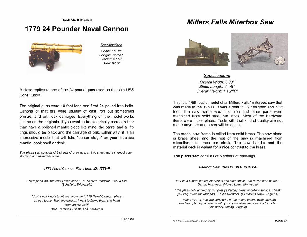
1779 24 Pounder Naval Cannon
Page 23
Specifications
Scale: 1/10th Length: 12-1/2" Height: 4-1/4"
Bore: 9/16"
A close replica to one of the 24 pound guns used on the ship USS
Constitution.
The original guns were 10 feet long and fired 24 pound iron balls.
Canons of that era were usually of cast iron but sometimes
bronze, and with oak carriages. Everything on the model works
just as on the originals. If you want to be historically correct rather
than have a polished mantle piece like mine, the barrel and all fit-
tings should be black and the carriage of oak. Either way, it is an
impressive model that will take "center stage" on your fireplace
mantle, book shelf or desk.
The plans set: consists of 8 sheets of drawings, an info sheet and a sheet of con-
struction and assembly notes.
1779 Naval Cannon Plans Item ID: 1779-P
"Your plans look the best I have seen." - H. Schultz, Industrial Tool & Die
(Schofield, Wisconsin)
"Just a quick note to let you know the "1779 Naval Cannon" plans
arrived today. They are great!!!. I want to frame them and hang
them on the wall!"
Dale Trammell - Santa Ana, California
WWW.MODEL-ENGINE-PLANS.COM Page 24
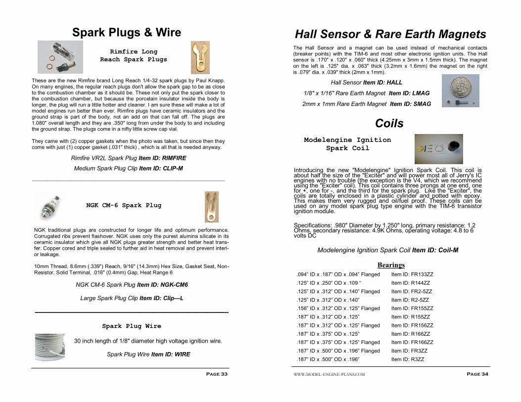
This is a 1/6th scale model of a "Millers Falls" miterbox saw that was made in the 1950's. It was a beautifully designed and built tool. The saw frame was cast iron and other parts were machined from solid steel bar stock. Most of the hardware items were nickel plated. Tools with that kind of quality are not made anymore and never will be again. The model saw frame is milled from solid brass. The saw blade is brass sheet and the rest of the saw is machined from miscellaneous brass bar stock. The saw handle and the material deck is walnut for a nice contrast to the brass. The plans set: consists of 5 sheets of drawings.
Miterbox Saw Item ID: MITERBOX-P
"You do a superb job on your prints and instructions, I've never seen better." -
Dennis Halverson (Moose Lake, Minnesota)
"The plans duly arrived by first post yesterday. What excellent service! Thank
you very much for your part." - Mike Durnford (Pembroke Dock, England)
"Thanks for ALL that you contribute to the model engine world and the machining hobby in general with your great plans and designs." - John
Guenther (Sterling, Virginia)
Millers Falls Miterbox Saw
Specifications
Overall Width: 3 38” Blade Length: 4 1/8”
Overall Height: 1 15/16"
Western Electric Telegraph Key &
Sounder
Page 25
Specifications
Key Sounder
Length-- 5-5/8" 5-1/2"
Width--- 2-1/8" 3"
Hight---- 1-3/4" 4-3/8"
The telegraph was the only long distance instant communication device until radio and other means came along. Railroads were always the largest users of the telegraph and utilized them for more than a century. The railroads would have had a very hard time operating safely and efficiently without them. The full size plans will allow you to make an exact replica of the key and sounder. The photo above is the "real thing" antique originals. The originals were made in a time when quality was of prime importance and esthetics ran a close second! These instruments were made of brass and steel, as were all manner of other types of instruments. You will want to make yours of these materials as well. You can make an operating set, or as non-operating shelf models. Either way, you can make them full size or reduce the size for really neat items to put in your curio cabinet or as a unique desk ornament set. The plans set: consists of 10 sheets of drawings.
Telegraph Key Plans Item ID: TELEGRAPH-P
"Just to let you know that the plans have arrived and I am very pleased with them,
they are very detailed and I am looking forward to building the key and sounder. Many thanks! - John Wellings, Birmingham, United Kingdom.
WWW.MODEL-ENGINE-PLANS.COM Page 26
Attachments & Tools
Precision Mini Drill
Specifications
Recommended Chuck Albrecht 65-J1 Drilling Capacity 0 - 1/4"
The Precision Mini Drill Press is designed to handle up to 1/4" (.250") drill bits. It fills a need for a drill press between my Micro Drill Press and the regular commercial 1/2" to 5/8" bench drill presses. The unit is machined primarily from aluminum alloy bar stock and drill rod and the base is machined from a cast iron lifting weight. The drill press features an adjustable quill depth stop, quill lock, a shop made electro-magnetic base/table and provisions for a 2" travel dial drilling depth indicator for high precision drilling depth. It is powered by a high torque 2-1/2" diameter permanent magnet field DC ball bearing motor. Speed can be adjusted using a variable voltage DC power supply, and/or also by choosing one of three steps on the pulleys. There are a lot of other ways that you can think of to power yours. One is to use a universal type AC motor such as on a sewing machine and a light dimmer to vary the RPM. The quill feed is by standard rack and pinion gear. The plans set: consists of 10 sheets of drawings and 1 sheet of construction notes.
Mini Drill Press Plans Item ID: MINIDRILL-P
"As an experienced mechanical draftsman (in a past career!), I can appreciate the
detail and quality of the drawings." - Lawrence Keating (Victoria, British Columbia, Canada)
Page 27
Micro Drill Press
Specifications
Quill Diameter: 1/2" Quill Travel: 1/2"
Throat Depth: 1-3/4" Drill Capacity: 1/16"
Height: Approx. 7"
How many times have you tried to drill really small holes using a big clumsy drill press? Oh, and how many broken drill bits & ruined work pieces? Well, having been there and done all that; in the early 1970's I designed and built this really sensitive miniature drill press for the small work. I use it on a regular basis and it has served me very well over the years. There is zero backlash in the quill feed and with just 3/8" quill travel with each turn of the down feed knob, control of the drill bit is a cinch! There is a graduated depth stop and if desired, you could mount a small dial indicator for precise depth control on yours. An optional shop made electro-magnet is built into the base directly below the spindle to hold ferrous workpieces or your own holding device for non ferrous materials. This has proven to be a valuable asset to the utility of the drill press. The magnet pole is not visible in this photo. The drill head moves up and down and will swivel around the column to accommodate the work. I routinely drill .006" holes with my drill press you will be able to reliably drill holes in metal down to .004" diameter should the need arise. It is capable of drilling holes up to .063" (1/16"). Many shops will have lots of uses for this easy to build bar stock tool. The plans set: consists of 6 sheets of drawings and a sheet of construction and assembly notes.
Micro Drill Press Plans Item ID: MICRODRILL-P
"I just received my plans, they are great!!" - O.H. Wachsmuth (Laguna Niguel, CA)
Page 28 WWW.MODEL-ENGINE-PLANS.COM
High Speed Auxiliary Mill Spindle
An easy to make auxiliary high speed spindle that will allow you to utilize very small diameter end mills without a high probability of breakage. Spin-dle RPM's of most home shop milling machines are simply too slow for end mills smaller than around 1/16" (1.6mm). Depending on the motor used and the pulley ratio, speeds of 8,000 RPM and much higher are available. The spindle is designed to accept 3/16” shank diameter end mills which is common for end mills from 1/32" to 3/16" diameter. The spindle body is mounted in a standard 3/4" or 7/8" R-8 collet. The drive belt is a standard low cost "O" ring. The unit is adaptable to a wide range of modifications to suit any user. The plans set also includes an oversize computer grade precision lower ball bearing, a high quality upper ball bearing and a bearing preload wave washer.
The plans set: consists of 5 sheets of drawings, 1 sheet of helpful notes, spindle
bearings & preload washer.
Mill Spindle Plans Item ID: SPINDLE-P
"I remember seeing your display at the 1995 NAMES show and was very im-
pressed with the quality of your plans and designs." - Michael A. Latcha
(Farmington Hills, Michigan)
“I’ve checked over the very excellent drawings and am impressed. I'm an ex-
Boeing design engineer, and I've worked with a lot of drawings and yours impress
me.” - Jack M. Nuckols (Hanson, Idaho)
"Your drawings and instructions are very clear and concise. My background was in aviation and aerospace manufacturing and I really appreciate prints that are clearly
presentable." - Jim Headberg, Headberg Aviation (Wellington, Florida)
Page 29
Mini Propane Burner & Regulator
I needed the ability to adjust flame size over a wide range and to be able to "set it
and leave it" for a half dozen or so engines that I have running at shows and not have one of them run out of fuel and come to a stop while I was talking to builders like you.
I also wanted the ability to have a sideways flame for my "Sideshaft" and "4-in-1" Vacuum Engines and some future projects. These low pressure burners have an
air adjustment that allows control of the flame (yellow tipped - to blue with an intense light blue inner cone) as well as the flame size.
There is also design information and a cut-away drawing of a neat and compact pressure regulator. Gas pressure can be adjusted from zero to more than the burner needs - about 8 lbs. per square inch. There is also a parts layout for an
excess flow valve which will permit safe use of flexible tubing rather than piping to supply gas to the burner.
You can have accurate speed control of your stirling and atmospheric engines. Also, your atmospheric engines will stay clean inside instead of getting gummed up from using an alcohol flame. A $2.00 bottle of propane will operate a burner for
around 70 hours! You and your "hot-air" engine projects will benefit from being operated with a powerful mini propane burner that is only 2" high! 1/8" bore x 1/4 OD silicone tubing should be used with the burners. The burners
can get fairly warm in use and the vinyl aquarium tubing or other plastic tubing that you might be inclined to use to connect the burner to the propane source will soften
and may come off the burner hose fitting. The silicone tubing is very soft and flexible, will withstand the temperature of molten solder, really clings to metal hose fittings and will not take a set or become hard with age. Hobby shops that sell
model airplanes and engines will have this.
The plans set: consists of 3 sheets of drawings and a sheet of construction and
assembly notes.
Propane Burner Plans Item ID: BURNER-P
"I got your plans, thanks. Excellent quality. They are much better than the usual
sort of rubbish I find in the UK." - Danny Quinlan (Brentwood, Essex, England)
WWW.MODEL-ENGINE-PLANS.COM Page 30
Gear Cutting Without Index Plates
Do accurate gear cutt ing (or other c irc le div id-
ing) up to 100 teeth (or div is ions) on your rotary
table without use of expensive index plates.
(For the folks who do not have computers to do
the calculations!)
Tables of direct dial settings calculated to 18 decimal places and are accurate to 1 second of arc, which is only 1/3600th degree! There are no cumulative errors as you cut gears or divide circles. You could calculate these yourself, but for just a 26 tooth gear you will have to make 78 calculations and hope that they are all correct! Degrees, minutes and seconds are needed for each tooth. If your rotary table dial doesn't include seconds, just round them to the nearest 1/4 or 1/2 degree.
The tables include the direct dial settings for every gear from 8 to 100 teeth, plus tables of gear pitch diameters for 14 pitches in a range from 6 to 120. Also, there are formulas and examples to calculate various other aspects of gears.
Gear Cutting Plans Item ID: GEAR-T
Metal Lathe Ball & Radius Turning Attachment
This heavy duty radius attachment was designed
for an Emco Maier "Maximat Super 11" lathe but it can be resized and/or modified to fit most 9"and larger machines.
It will turn convex radii up to 3" diameter and con-cave radii up to 4-1/2". There are fine feed screws
on both X and Y axis movement for accurate con-trol of radii on the work piece, allowing for flanges on hemispheres and other circumstances. The unit features dovetail slides with integral adjustable gibs.
The tool holder is designed for maximum flexibility in positioning the tool. All com-ponent parts are very heavily designed and the pivot system has a very large
bearing area. Sooner or later most machinists will need this type of attachment for the lathe.
The plans set: consists of 6 sheets of drawings.
Metal Lathe Ball Plans Item ID: BALL-P
Page 31
Gas Engine Propane Demand Valve
"Propane is burned in some miniature engines rather than gasoline or alcohol. The exhaust produced is not as offensive and the engine runs cleaner. Small propane cylinders are used. A pressure regulator is fastened to the bottle to allow a regulated flow. The flow is then attached to the inlet side of the demand valve where it cannot escape. The outlet side of the demand valve is attached to the engine carburetor. During the intake stroke of the engine a vacuum demand is created. This demand (suction) trips the needle in the demand valve and allows a flow of propane to the engine. When the demand stops so does the propane flow. Scuba divers have a similar device on their tanks to allow a flow of air on demand." - Chuck Harty Disclaimer: These plans are for basic information only and are not intended to be "plans for construction". These drawings represent what the author has done and we have no way to supervise your design, workmanship or selection of materials. If you purchase these plans and/or make any similar devices based on these drawings, we will not be held responsible in any way if for any reason if accident occurs. The plan set: consist of one sheet with drawings, assembly and operation notes.
propane can be hazard-ous! Conversely, when proper care and pre-
cautions are taken and common sense is used,
it can also be very
safe.
Page 32 WWW.MODEL-ENGINE-PLANS.COM
Ignition Systems
Transistor Ignition Modules
Building Transistor Ignition Modules - You can
build them yourself from kits for peanuts.
TIM-6c
For use with 6 volt batteries (or 4.8 minimum to 7 volts maximum) on any engine type.
Kit contains: (1) TIP42C Transistor, (1) 2N2907A Transistor, (4) Resis-tors, (1) LED Timing Light, (1) 3 Amp. 40 volt reverse polarity protection diode, (1) Hall Effect Magnetic Sensor, (1) Length of Heat small plastic tubing to insulate the Hall Sensor leads, (1) Rare Earth Magnet, (1) Drilled Printed Circuit Board, Circuit Diagrams and Construction Notes.
The circuit board is approximately 1.35" wide by 1.70" long. Just to the left of the circuit board is the Hall Effect sensor and the dot just above it is the rare earth magnet which is just 1/8" in diameter and 1/16" thick (3.2mm x 1.6mm).
Same as above, except also includes a high quality PCB Screw Type Terminal Strip for ease of connecting or removing your battery, coil, and other wires.
Deluxe TIM-6c Item ID: TIM-6CD
Deluxe TIM-6c Fully Assembled and Tested Item ID: TIM-6CDA
Page 33
Spark Plugs & Wire
Rimfire Long
Reach Spark Plugs
These are the new Rimfire brand Long Reach 1/4-32 spark plugs by Paul Knapp.
On many engines, the regular reach plugs don't allow the spark gap to be as close to the combustion chamber as it should be. These not only put the spark closer to the combustion chamber, but because the porcelain insulator inside the body is
longer, the plug will run a little hotter and cleaner. I am sure these will make a lot of model engines run better than ever. Rimfire plugs have ceramic insulators and the ground strap is part of the body, not an add on that can fall off. The plugs are
1.080" overall length and they are .350" long from under the body to and including the ground strap. The plugs come in a nifty little screw cap vial.
They came with (2) copper gaskets when the photo was taken, but since then they come with just (1) copper gasket (.031" thick) , which is all that is needed anyway.
NGK traditional plugs are constructed for longer life and optimum performance.
Corrugated ribs prevent flashover. NGK uses only the purest alumina silicate in its ceramic insulator which give all NGK plugs greater strength and better heat trans-fer. Copper cored and triple sealed to further aid in heat removal and prevent interi-
Resistor, Solid Terminal, .016" (0.4mm) Gap, Heat Range 6
NGK CM-6 Spark Plug Item ID: NGK-CM6
Large Spark Plug Clip Item ID: Clip—L
————————————————————————————————--
Spark Plug Wire
30 inch length of 1/8" diameter high voltage ignition wire.
Spark Plug Wire Item ID: WIRE
WWW.MODEL-ENGINE-PLANS.COM
Page 34
Hall Sensor & Rare Earth Magnets The Hall Sensor and a magnet can be used instead of mechanical contacts (breaker points) with the TIM-6 and most other electronic ignition units. The Hall sensor is .170" x .120" x .060" thick (4.25mm x 3mm x 1.5mm thick). The magnet
on the left is .125" dia. x .063" thick (3.2mm x 1.6mm) the magnet on the right
is .079" dia. x .039" thick (2mm x 1mm).
Hall Sensor Item ID: HALL
1/8" x 1/16" Rare Earth Magnet Item ID: LMAG
2mm x 1mm Rare Earth Magnet Item ID: SMAG
Coils
Modelengine Ignition
Spark Coil
Introducing the new "Modelengine" Ignition Spark Coil. This coil is about half the size of the "Exciter" and will power most all of Jerry's IC engines with no trouble (the exception is the V4, which we recommend using the "Exciter" coil). This coil contains three prongs at one end, one for +, one for -, and the third for the spark plug. Like the "Exciter", the coils are totally enclosed in a plastic cylinder and potted with epoxy. This makes them very rugged and oil/fuel proof. These coils can be used on any model spark plug type engine with the TIM-6 transistor ignition module.
Specifications: .980" Diameter by 1.250" long, primary resistance: 1.2 Ohms, secondary resistance: 4.9K Ohms, operating voltage: 4.8 to 6 volts DC
Modelengine Ignition Spark Coil Item ID: Coil-M
Bearings .094” ID x .187” OD x .094” Flanged Item ID: FR133ZZ
.125” ID x .250” OD x .109 “ Item ID: R144ZZ
.125” ID x .312” OD x .140” Flanged Item ID: FR2-5ZZ
.125” ID x .312” OD x .140” Item ID: R2-5ZZ
.156” ID x .312” OD x .125” Flanged Item ID: FR155ZZ
.187” ID x .312” OD x .125” Item ID: R155ZZ
.187” ID x .312” OD x .125” Flanged Item ID: FR156ZZ
.187” ID x .375” OD x .125” Item ID: R166ZZ
.187” ID x .375” OD x .125” Flanged Item ID: FR166ZZ
.187” ID x .500” OD x .196” Flanged Item ID: FR3ZZ
.187” ID x .500” OD x .196” Item ID: R3ZZ
Page 35
Bearings—cont.
.250” ID x .375” OD x .125” Item ID: R168ZZ
.250” ID x .375” OD x .125 Flanged Item ID: FR168ZZ
.250” ID x .500” OD x .187” Item ID: R188ZZ
8mm ID x 22mm OD x 7mm Item ID: 608ZZ
.375” ID x .625” OD x .157” Item ID: R1038ZZ
.375” ID x .875” OD x .281” Item ID: R6ZZ
.375” ID x .875” OD x .281” Sealed Item ID: R6-2RS
10mm x 19mm x 5mm Item ID: 6800ZZ
12mm x 21mm x 5mm Item ID: 6801ZZ
12mm x 28mm x 8mm Item ID: 6001ZZ
.500” ID x .750” OD x .156” Item ID: R1212ZZ
.500” ID x 1.125” OD x .312” Item ID: R82RS
.500” ID x 1.375” OD x .437” Item ID: 1621ZZ
Miscellaneous Items
Super Fine .001" Fuel Filter Almost all fuel has some very fine lint in it and your model gas engine needle jets are too small for some of it to pass. These filters will not pass any particle larger than .001" and will probably solve those "mysterious" fuel adjustment problems you may now have. Size: 1" dia x .005" thick with drawing.
Graphite is great material to use for your Stirling/Atmospheric engine power piston. This is the same graphite used in all our Graphite & Bearing sets (see article on website.) You can
now order additional quantities for other projects as well. Quantities over 5" in length will be cut to fit in our 5" long shipping boxes.
1" Length of 5/8" Dia Graphite ITEM-ID: GRAPHITE58
1" Length of 1" Dia Graphite ITEM-ID: GRAPHITE1
V4 Distributor Cap
This cap is slightly different than the one used in the original plans. This cap has 'ears' to
fasten it to the distributor body instead of the two clips. Should be simple enough to adjust the plans to accommodate this cap, as the old style cap is no longer available.
Includes 5 contact eyelets.
V4 Distributor Cap ITEM-ID: V4-DIST
BOOKS
Ignition Coils and Magnetos in Miniature
by Bob Shores
“The most significant contribution I have made to the small gas engine hobby was to publish this book in 1997.” The book was written to correct many misconceptions concerning ignition coils and magnetos and to provide working information to design, build, apply and troubleshoot ignition systems. This book also provides information to build miniature ignition coils, magnetos and a coil winder. It is a 281
page, 21 chapters, library quality handbook with gold lettering containing 116 drawings and illustrations. The book is written in layman’s terms. Technical terms and “buzz words” are avoided for easy understanding.
Ignition Coils & Mag. Miniatures Item ID: COIL-BK
________________________________________
The Home Machinist Handbook (Beginners)
Here’s everything the do-it-yourselfer needs to set up, and operate a handy-man’s machine shop. Areas covered range from shop requirements and proper lighting to buying, using, and storing tools. A lot has been written about machine tools and how they are used to make parts. Most books and literature on the subject are written in very technical terms for the professional machinist,
someone interested in obtaining high volume production rates at the lowest cost. These books assume that the machinist has unlimited funds and can equip his shop with the very latest and best equipment. This book is different. It is written for the nonprofessional, the man who wants to work on a few projects at home. Or the hobbyist who wants to make a few parts for his radio-controlled airplane or boat, the model railroader or anyone repairing a clock. It is intended for the inventor who needs to try out his latest idea, or the engineer.
Machinists use machine tools, such as lathes, mill-ing machines, and spindles, to produce precision metal parts and the machine operator or vocational student must know the basics to succeed as a ma-chinists. This title helps you define tools and use them properly and safely. It offers review questions
for students, and answers your needs on the job and to use the right tool the right way. Here, fully updated to include new ma-chines and electronic/digital controls, is the ultimate guide to basic machine shop equipment and how to use it. Whether you’re a pro-fessional machinist, an apprentice, a trade student, or a handy homeowner, this fully illustrated volume helps you define tools and use them properly and safely. (more info on this book http://www.model-engine-plans.com/books/index.htm )
Machine Shop Basics Item ID: SHOPBASIC-BK
_______________________________________
Machine Shop Tools & Operations (Intermediate)
The primary focus for a machinist is the machines themselves. This book covers machine tools, such as lathes, milling machines, and spindles, to pro-duce precision metal parts. Make your shop safe and smart. If you’re a machinist or a student of the trade, this second volume in Audel’s machine shop
library offers concise, to-the-point coverage of everything you need to know. You’ll find definitions of all the shop tools; guide-lines for set-up, safe operation, maintenance, and repair; illustra-tions and diagrams; review questions for students, and much more. Expect it to become one of your most used tools. Master all types of saws, drills, lathes, milling machinery, metal-finishing ma-chines, and more. Learn safe operating procedures for cutting tools and how to mount work in the machines. Find current details on new machines with electronic/digital controls. Understand how ultrasonic is used in metalworking. Explore information on ma-chine shop robotics and electronics. Discover valuable tips for hobbyists, woodworkers, and home-shop owners.
Jerry Howell has been well known in the model engineering hobby for a number of years. He regularly attended shows almost every year with a beautiful display of engines he has de-signed. The engines he has designed no doubt grace many a desk or mantel of proud builders around the world. Jerry always went the extra step beyond just making engines to that of de-signing and producing plans and kits so that others can make them as well. His plans go an extra step not usually found in engine kits, and that is to show complicated parts at several stages of completion, making it easier for a novice to take a raw block of metal to a finished engine block.
His legacy will carry on through his sons as they continue the business/hobby their Dad loved. Those who met and knew Jerry felt his passion for his work and made everyone feel at ease with his gift of knowledge and communi-cation through his work and skills. Jerry was a very gifted craftsman and his life and work will never be forgotten as he left the world a better place with his passion and zeal for life and in what he did and believed in.