53
Jerrik Inc. A CONESYS COMPANY Filter and Transient Suppression Connectors MILITARY AEROSPACE TRANSPORTATION GEOPHYSICAL INDUSTRIAL

Jerrik Inc.A CONESYS COMPANY
Filter and TransientSuppression Connectors
MILITARY AEROSPACE TRANSPORTATION GEOPHYSICAL INDUSTRIAL

1www.conesys.com [email protected]
Jerrik Inc.Table of Contents
Filter and Transient Suppression Connectors
– –
Introduction . . . . . . . . . . . . . . . . . . . . . . . . . . . . . . . . . . . . . . . . . . . . . . . . . . . . . . . . . . . . . . . . . . . . 2Why Filters in a Connector? . . . . . . . . . . . . . . . . . . . . . . . . . . . . . . . . . . . . . . . . . . . . . . . . . . . . . . . . . 2 – 3Design Guide – Termination Selection . . . . . . . . . . . . . . . . . . . . . . . . . . . . . . . . . . . . . . . . . . . . . . . . . . . 4Circular Filter Connector Part Number Development . . . . . . . . . . . . . . . . . . . . . . . . . . . . . . . . . . . . . . 5MIL-DTL-38999 Insert Arrangement . . . . . . . . . . . . . . . . . . . . . . . . . . . . . . . . . . . . . . . . . . . . . . . . . . . 6 – 8Mechanical and Environmental Performance . . . . . . . . . . . . . . . . . . . . . . . . . . . . . . . . . . . . . . 9Electrical Performance . . . . . . . . . . . . . . . . . . . . . . . . . . . . . . . . . . . . . . . . . . . . . . . . . . . . . 10 –11Typical ‘Pi’ Filter Construction . . . . . . . . . . . . . . . . . . . . . . . . . . . . . . . . . . . . . . . . . . . . . . . . . . . . . 12Sealed Connectors . . . . . . . . . . . . . . . . . . . . . . . . . . . . . . . . . . . . . . . . . . . . . . . . . . . . . . . . . . . 13TVS Connectors . . . . . . . . . . . . . . . . . . . . . . . . . . . . . . . . . . . . . . . . . . . . . . . . . . . . . . . . . . . 14MIL-DTL-38999 Filter Connectors . . . . . . . . . . . . . . . . . . . . . . . . . . . . . . . . . . . . . . . . . . . . . .15 – 24MS27468 (Series I) Jam Nut Receptacle . . . . . . . . . . . . . . . . . . . . . . . . . . . . . . . . . . . . . . . . . . . . . . . . . . 16MS27466 and MS27496 (Series I) Wall Mount Receptacles . . . . . . . . . . . . . . . . . . . . . . . . . . . . . . . . . 17MS27505 (Series I) Box Mount Receptacle . . . . . . . . . . . . . . . . . . . . . . . . . . . . . . . . . . . . . . . . . . . . . . . . . 18MS27474 (Series II) Jam Nut Receptacle . . . . . . . . . . . . . . . . . . . . . . . . . . . . . . . . . . . . . . . . . . . . . . . . . . . 19MS27508 and MS27497 (Series II) Wall and Box Mount Receptacles . . . . . . . . . . . . . . . . . . . . . . 20M38999/20 (Series III) Wall Mount Receptacle . . . . . . . . . . . . . . . . . . . . . . . . . . . . . . . . . . . . . . . . . . . . . .2 1M38999/24 (Series III) Jam Nut Receptacle . . . . . . . . . . . . . . . . . . . . . . . . . . . . . . . . . . . . . . . . . . . . . . . . 22M38999/40 (Series IV) Wall Mount Receptacle . . . . . . . . . . . . . . . . . . . . . . . . . . . . . . . . . . . . . . . . . . . . . 23M38999/44 (Series IV) Jam Nut Receptacle . . . . . . . . . . . . . . . . . . . . . . . . . . . . . . . . . . . . . . . . . . . . . . . . 24MIL-DTL-26482 Series 2 Filter Connectors . . . . . . . . . . . . . . . . . . . . . . . . . . . . . . . . . . . . . 25 – 31MIL-DTL-26482 Series 2 Part Number Development . . . . . . . . . . . . . . . . . . . . . . . . . . . . . . . . . . . . . . . 26Insert Arrangement . . . . . . . . . . . . . . . . . . . . . . . . . . . . . . . . . . . . . . . . . . . . . . . . . . . . . . . . . . . . . . . . 27 – 28MS 3470 (Series 2) Wall Mount Receptacle . . . . . . . . . . . . . . . . . . . . . . . . . . . . . . . . . . . . . . . . . . 29MS 3474 (Series 2) Jam Nut Receptacle . . . . . . . . . . . . . . . . . . . . . . . . . . . . . . . . . . . . . . . . . . . 30MIL-DTL-24308 D-Sub and MIL-DTL-83513 Part Number Development . . . . . . . . . . . . . . . . . 31MIL-DTL-24308 Filter Connectors . . . . . . . . . . . . . . . . . . . . . . . . . . . . . . . . . . . . . . . . . . . . . . 32 – 35MIL-DTL-24308 D-Sub . . . . . . . . . . . . . . . . . . . . . . . . . . . . . . . . . . . . . . . . . . . . . . . . . . . . . . . 33MIL-DTL-83513 Filter Connectors . . . . . . . . . . . . . . . . . . . . . . . . . . . . . . . . . . . . . . . . . . . . . 36 – 37MIL-DTL-83513 Micro-D . . . . . . . . . . . . . . . . . . . . . . . . . . . . . . . . . . . . . . . . . . . . . . . . . . . . . . . . 37ARINC 404, ARINC 600, and EPX® Part Number Development . . . . . . . . . . . . . . . . . . . . . . . . . . . . . . 38ARINC 404 Filter Connectors . . . . . . . . . . . . . . . . . . . . . . . . . . . . . . . . . . . . . . . . . . . . . . . . . 39 – 43ARINC 404 Insert Arrangement . . . . . . . . . . . . . . . . . . . . . . . . . . . . . . . . . . . . . . . . . . . . . . . . . . . . . . . . . . 40ARINC 404/MIL-C-81659 Size 1 and Size 2 . . . . . . . . . . . . . . . . . . . . . . . . . . . . . . . . . . . . . . . . . . . . . . . . 41ARINC 404/MIL-C-81659 Size 3. . . . . . . . . . . . . . . . . . . . . . . . . . . . . . . . . . . . . . . . . . . . . . . . . . . . . . . . . . . 42ARINC 404/MIL-C-81659 Size 4 . . . . . . . . . . . . . . . . . . . . . . . . . . . . . . . . . . . . . . . . . . . . . . . . . . . . . . . . . . 43ARINC 600 Filter Connectors . . . . . . . . . . . . . . . . . . . . . . . . . . . . . . . . . . . . . . . . . . . . . . . . . . 44 – 48Insert Arrangement . . . . . . . . . . . . . . . . . . . . . . . . . . . . . . . . . . . . . . . . . . . . . . . . . . . . . . . . . . . . . . . . . . . . 45ARINC 600 Size 1 . . . . . . . . . . . . . . . . . . . . . . . . . . . . . . . . . . . . . . . . . . . . . . . . . . . . . . . . . . . . . . . . . . . . . . . . 46ARINC 600 Size 2 . . . . . . . . . . . . . . . . . . . . . . . . . . . . . . . . . . . . . . . . . . . . . . . . . . . . . . . . . . . . . . . . . . . . . . . . 47ARINC 600 Size 3 . . . . . . . . . . . . . . . . . . . . . . . . . . . . . . . . . . . . . . . . . . . . . . . . . . . . . . . . . . . . . . . . . . . . . . . . 48EPX® Filter Connectors . . . . . . . . . . . . . . . . . . . . . . . . . . . . . . . . . . . . . . . . . . . . . . . . . . . . . . 49 – 50

2www.conesys.com [email protected]
Jerrik Inc.IntroductionFilter and Transient Suppression Connectors
– –2
Jerrik Inc.
Jerrik, located in Tempe Arizona, is a premiere designer andmanufacturer of EMI filter and transient suppression con-nectors. Our high reliability, high performance productsserve many industries including commercial and militaryavionics, transportation, automotive and telecommunications.The Jerrik facility is certified to ISO9001:2000/AS9100 aswell as other customer specific requirements.We specializein manufacturing connectors that meet various militaryspecifications and custom configurations. These productstake advantage of the latest design, material and manufac-turing standards in our industry.
Jerrik is continually looking to improve our products andour processes. Our filter connectors offer planar array andchip capacitor solutions for design flexibility orcustomer preference. In addition, we employ severalgenerations of diode and MOV designs to offer the marketthe best transient voltage suppression solutions.
We are committed to excellence and quality in our productsas well as responsiveness and integrity in our customer service.
As a part of the Conesys family, Jerrik can offer the marketeven more strengths in connector manufacturing. Ourproducts ship all over the globe, and we take pride in ourcustomer service both domestic and international. Thiscatalog covers many aspects of filter connector selection.Please feel free to contact our facility if you have a customapplication or need more information.
[email protected]: 480-730-5700
Why Filters in a Connector?
Theory and TypesIf your circuitry is suffering the ill effects of interferencefrom radio waves, stray transmissions, electric power linesor electric motor noise, you are experiencing EMI (electro-magnetic interference). This leads the circuit designer toconsider EMI filters. A second issue, EMP (electromagneticpulse) is driven from the catastrophic effects of extremelyhigh voltage, short duration pulses of energy. Traditionally,concern for nuclear attack was high priority and now in themilitary and aerospace environments, protection fromlightning strikes and similar high energy sources are a toppriority. Protection from this sudden unwanted over-voltagesituation is more commonly referred to as TVS (transientvoltage suppression).
EMI and EMP are looking for a path to your circuits and thatpath is usually an antenna or a cable set running to the circuitthat is acting as an antenna.
The key warrior against EMI is a capacitor element. Typically,we battle transient voltage with a zener diode.Where is the bestplace to put these elements? Often military and avionics boxeshouse the critical circuitry. If the cable set is the antenna thenthe best placement for the filter is at the cable/box interface,preventing the unwanted signals from entering the system.A multi-pin filter or TVS connector is the ideal solution.

Components for EMIMost filters are low pass, allowing signal to pass while elimi-nating high frequency noise. In circuit design, two capacitorsin parallel running from source to ground, surrounding aninductor in series, is the most effective EMI filter. This is knownas a Pi filter (shown below). The advantage of the Pi filter isthat it generates the fastest roll-off and highest attenuationlevels of any of the popular filter types. The second mostpopular type, the ‘C’ filter, is comprised of one capacitorelement from signal to ground.With fewer components, the‘C’ filter can often generate the best performance/price ratio.
Other filter types that Jerrik can package include ‘T’ filters,‘LC’, and ‘CL’. Consult with your Jerrik factory representativefor advice on which circuit is best for your application.
Since the connector is the best place for the filter, packagingthe ceramic capacitor inside the shell is the design goal. Toachieve the maximum filtering performance Jerrik uses planararray capacitors. These monolithic devices have the entirepattern drilled in the ceramic, thus supporting capacitancefrom signal to ground at every pin in the connector. To buildthe Pi filter, two arrays are used with a tubular ferromagneticinductor on every pin (see page 12 for typical connectorconstruction).
Jerrik also filters using off the shelf chip capacitors on printedcircuit boards (PCB). This PCB design offers the advantagesof lower price at the sacrifice of performance. The attenuationperformance will start high at low frequency but will not stayhigh at higher frequencies, thus demonstrating a ‘knee’ shapedcurve. For high frequency applications Jerrik recommendsplanar capacitors construction.
3www.conesys.com [email protected]
Jerrik Inc.Why Filters in a Connector?
Filter and Transient Suppression Connectors
– –
Components for EMP/TVSZener diodes are packaged in the Jerrik TVS connectors fora number of applications. On average every commercialaircraft is struck by lightning twice a year. Aircraft are nowbeing designed structurally with up to 50% compositecontent and have ‘all electric’ flight control systems. Today’sindustry standard for lightning testing of electronics isRTCA DO-160, written for conventional aluminum airframes.As such, it may prove lacking for next generation aircraft.Jerrik designs TVS connectors application specific andmeeting industry’s changing requirements. Jerrik TransientVoltage Suppression connectors save space, are lighter, morereliable and more cost effective than current industrystandards. Consult with your Jerrik factory representativefor the very latest design technology.
Your applicationMeeting your EMI/EMP or TVS needs electrically is only halfof the Jerrik SOLUTION. You’ll need the connector to fit andfunction mechanically as well. With filters housed at the boxinterface, over 90% of our products are box mount or jam nutreceptacle style connectors. This is true for circular connectorsas well as our high-end ARINC blind mate filter connectors.In addition, Jerrik provides the customer with exact fits forboard mounting PC tail contacts. See page 4 for availablecontact termination styles.
38999 QualificationJerrik designs filter connectors to meet today’s military andcommercial connector standards. MIL-DTL-38999 is a ‘gold’standard for performance in many environments. As appli-cable, all Jerrik connectors are designed with this level ofquality and performance. Today’s aerospace and ground troopapplications demand even higher performance. Consult yourJerrik factory representative if your application requirestesting above and beyond this standard.
‘Pi’ �lter ‘C’ �lter

Solder Cup PC Tail Crimp
4www.conesys.com [email protected]
Jerrik Inc.Design Guide – Termination SelectionFilter and Transient Suppression Connectors
– –
Design Considerations
Circular or Rectangular
MIL-DTL-38999 SeriesI,II,III,IV
MIL-DTL-26482Series 2
MIL-DTL-24308MIL-DTL-83513
ARINC 404ARINC 600
EPX®
Mating End Contacts
Pin or Socket
Filter Type
C and/or Pi and/or TVS
Maximum or Mixed Capacitance Requirement? _______ pF
Other Electrical?
Feed Thru Contacts Ground Contacts DWV min ______ VDC
Other Environmental?
Thermal Cycle, Thermal Shock, Burn-In, SEALED
Other Mechanical?
Mounting Hardware (clinch nut, helicoil, board mount shell features)
Contact Terminations
Soldercup or PC Tails (or wirewrap) or Crimp
.260
.220
[ B [ C
A
[ E
D STANDARD MSTERMINATEDCRIMP CONTACT
FRONT BACKPACKINSULATOR
REAR BACKPACKINSULATOR
RETAINING CLIP
GROMMETFIXED FILTERPACKAGE
Contact Size
A � B � C D � E
inch mm inch mm inch mm inch mm inch mm
#22 .110/.094 2.79/2.39 .040/.035 1.02/0.89 .049 .047 1.24/1.19 .180/.120 4.57/3.05 .022/.018 0.56/0.46
#20 .110/.094 2.79/2.39 .048/.042 1.22/1.07 .061/.057 1.55/1.45 .180/.120 4.57/3.05 .032/.028 0.81/0.71
#16 .172/.141 4.37/3.58 .082/.069 2.08/1.75 .103/.097 2.62/2.46 .180/.120 4.57/3.05 .042/.038 1.07/0.97
#12 .172/.141 4.37/3.58 .120/.112 3.05/2.85 .142/.136 3.61/3.45 .180/.120 4.57/3.05 .065/.061 1.65/1.55

5www.conesys.com [email protected]
MIL-DTL-38999Part Number DevelopmentCircular Filter Connectors
Jerrik Part Number Development
– –
Filter J 99 1 B S C N 35 B P A N
Shell Configuration
99 = MIL-DTL-38999
Series
1, 2, 3, 4, (for I, II, III, IV)
Shell Style
B = Back Panel Mount Wall/Box Mount Receptacle (Series I, II)
W = Wall Mount Receptacle (Series III, IV)
J = Jam Nut Receptacle
F = Front Panel Mount Wall/Box Receptacle (Series I, II)
Termination Type
S = Solder Cup
P = PC Tail
C = Crimp
W = Wire Wrap
Shell Sizes
A=8/9, B =10/11, C=12/13, D=14/15, E=16/17, F=18/19, G=20/21, H=22/23, J=24/25
Shell Finish
N = Electroless Nickel
O = Olive Drab Cadmium Nickel
P = Passivated Stainless Steel
D = Electro-deposited Nickel over Stainless Steel
Y = Yellow Chromate Cadmium
Contact Arrangement or Number of Contacts
See pages 5–7
Filter Characteristics
A = PL, B = PM, C = PT, D = PH, E = PVH, F = CL, G = CM, H = CT, J = CH, K = CVH (see pages 10–11)
Contact Type
P = Pin
S = Socket
Modifier
A = N/A
B = #4-40 Clinch Nut
C = #6-32 Clinch Nut
D = #4-40 Helicoil
E = #6-32 Helicoil
Polarization
K, N, W, X, Y, Z, A, B, C, or D

6www.conesys.com [email protected]
MIL-STD-1560Insert Arrangement (Pin Front View)for MIL-DTL-38999 Series I, II, III, and IV Connectors
Insert Arrangement Views
– –
1
23
4
56
9-35/8-35A35,
6 #22D
A
B
C
9-98/8-98A98,3 # 20
AB
11-2B2,
2 # 16
A
BC
D
11-4B4,
4 # 20
A
BC
D
E
11-5/10-5B5,
5 # 20
12
3
45
67
8
9
10 11
1213
11-35/10-35B35,
13 # 22D
A
B
CD
E F
11-98/10-98B98,6 # 20
A
B
CD
E
FG
11-99/10-99B99,7 # 20
A
B
C
12-3
3 # 16
A
B
C
D
13-4/12-4C4,
4 # 16
A
B
CD
E
F
G
H
13-8/12-8C8,8 # 20
13-35/12-35C35,
22 # 22D
AB
C
D
E
F
G
H
JK
13-98/12-98C98,
10 # 20
A
B
CD
E
15-5/14-5D5,
5 # 16
A
B
C
D
E
F
G
H
J
K
L
MR N
15-15/14-15D15,
1 # 16, 14 # 20
A
B
C
D
EFG
H
J
K
L
M N
P
RS
T U
15-18/14-18D18,
18 # 20
A B
C
D
E
FG
H
J
K
L
M
N P
R
ST
U V
15-19D19,
19 # 20
15-35/14-35D35,
37 # 22D
A
B
C
D
EF
G
H
J
K
L
M
15-97/14-97D97,
4 # 16, 8 # 20
A
B
C
D
E
F
17-6/16-6E6,
6 # 12
A
B
C
DE
F
G
H
17-8/16-8E8,
8 # 16
AB
C
D
E
F
G
HJK
LM
N
P
RS T
U
V
WX
Y
Z
a b
c
17-26/16-26E26,
26 # 20
17-35/16-35E35,
55 # 22D
P
1
3
4
9
10
16
17
24
25
31
32
39
40
46
47
52
53
55
1
15
22
21
14
21
1
31

7www.conesys.com [email protected]
MIL-STD-1560Insert Arrangement (Pin Front View)
for MIL-DTL-38999 Series I, II, III, and IV Connectors
Insert Arrangement Views
– –
17-99/16-99E99,
2 # 16, 21 # 20
19-11/18-11F11,
11 # 16
19-35/18-35F35,
66 #22D
18-53*
53 #22
21-11G11,
11 # 12
21-16/20-16G16,
16 # 16
21-75G75,
4 # 8 Twinax
A
B
C
D
E
L
F
G
H
J
K
AB
C
D
E
FG
HJK
L
M
N
P
RS T
U
V
W
X
Y Z
19-28/18-28F28,
2 # 16, 26 # 20
A
B
C
D
E
F
G
JKL
M
N
P
R
S
T
U
V
W
X
Y
Z
a
b
c
d
e
19-30/18-30F30,
1 # 16, 29 # 20
A
B
C
D
E
F
GH
J
K
L
M
N
P
RS
T
U
V
W
X
Y
Z
a
b
c
d
e
fg
1
3
4
9
10
16
17
24
25
33
34
42
43
50
51
57
58
63
64
66
19-32/18-32F32,
32 # 20
A
B
C
D
E
F
GJ
HKL
M
N
P
R
S
T
U
V
W
X
Y
Zab
c
d
e
f
g
h
j
A
B
C
DE
F
G
H
J
K
L
A
B
C
D
EF
G
H
J
K
L
M
N
P
R
S
21-41/20-41G41,
41 # 20
21-48**G48**,
4 # 8 Power
AB
CD
E
F
G
H
J
KLM
N
P
R
S
T
U
V
W
XY
Z
a
b
c
def
g
h
i
j
km
tn
pq
r
s
21-39/20-39G39,
2 # 16, 37 # 20
AB
C
D
E
F
G
H
JKL
M
N
P
RS
T
U
VX
YZ
W
a
b
c
de
f
g
h
ij
k
m
n
p
q
r
A
BC
D
A
B
C
D
23-21/22-21H21,
21 # 16
23-2*/22-2*
85 # 22
A
B
C
D
E
FG
H
J
K
L
M
N
P
R
S
TU
V
W
X
21-35/20-35G35,
79 # 22D
1
11
7121
31
41
51
61
79
1
11
21
31
52
51
53
1
4
5
11
12
19
20
28
29
38
39
47
48
57
58
66
67
74
75
81
82
85
*Inactive for new design (not available in series III).
**Not MIL-STD-1560 layout.

8www.conesys.com [email protected]
MIL-STD-1560Insert Arrangement (Pin Front View)for MIL-DTL-38999 Series I, II, III, and IV Connectors
– –
Insert Arrangement Views
J88 # 8 Twinax,
J119 # 10, 2 # 20,
25-24/24-24J24,
12 # 12, 12 # 16
23-53/22-53H53,
53 # 20
23-35/22-35H35,
100 # 22D
AB
C
D
E
F
G
HJ
K
L
M
N
P
RS
T
UV
W
X
Y
Za
bc
d
ef
g
h
km
n
pq
r
s
tu
vw
x
y
z
AABB
CC
DDEE
FF
GGHH
23-55/22-55H55,
55 # 20
a
bc
de
fg
H
i
j
km
np
qr
s
t
uv
wx
y
z
AB
C
D
E
F
G
HJK
L
M
N
P
R
S
TU
VW
XY
Z
AA
BB
CC
DDEEFF
GGHH
25-4/24-4J4,
8 # 16, 48 # 20
e
AB
CD
E
F
G
H
J
KL
MN
X
YZ
a
bc
d
f
g
h
k
mnP
R
S
T
U
V
W
p
q
r
s
t
uv
w
x
y
z
AA
BBCC
DD
EE
FF
GG
HH
JJ
KKLL
25-19/24-19J19,
19 # 12
A B
C
D
E
FGH
J
K
L
M
N P
R
ST
U V
25-43J43,
20 # 16, 23 # 20
AB
C
D
E
F
G
H
J
KLM
N
P
R
S
T
U
V
W
XY
Z
a
b
c
d
efg
h
k
m
n p
r
stu
v
w
x
q
25-29/24-29J29,
29# 16
AB
C
D
E
F
GHJ
K
L
M
N
P
RS T
U
V
W
XY
Z
a
b c
d
e
f
a
AB
C
D
E
F
GHJ
K
L
M
N
P
R
S
T
UV
W
X
Y
Z
25-46J46,
40 # 20, 4 # 16, 2 # 8 Coax
AB
C
D
E
F
G
H
JKL
M
N
P
R
S
T
U
VW
XY
Za
b
cd
efg
h
k
m
n
p
r
s
t u
v
w
xy
z
AA
q
25-61/24-61J61,
61 # 20
A
B
C
D
E
F
G
H
JK
LMN
P
R
S
T
U
V
W
X
YZa b
cd
e
f
g
h
jkm
n
P
r
s
t
uv
w
x
y
z
AABB
CC
DD
EE
FF
GGHH
JJ
KKLL
MM
NNPP
i
q
J90,40 # 20, 4 # 16, 2 # 8 Twinax
A
B
C
DE
F
GH
A
B
C
D
EF
G
H
L
J
K
J2010 # 20,13 # 16, 4 # 12, 3 # 8 Twinax,
AB
C
D
E
F
G
H
JKL
M
N
P
R
S
T
U
VW
XY
Za
b
cd
efg
h
k
m
n
p
r
s
t u
v
w
xy
z
AA
q
AB
C
D
E
F
G
H
J
K
L
M
N
P
R
S
T
U
VWX
Y
Z
1
23
4
5
67
1
2
3
5
6
8
715
16
24
25
34
35
45
46
55
4
56
66
67
76
77
85
86
93
94
95
9697
98
99
10 0
25-35/24-35J35,
128 # 22D
1
4
7
8
14
15
24
25
35
36
47
48
58
59
70
71
81
8294
105
115
122
125
12111 4
10493
23-32/22-32H32,
32 # 20
A
B
C
D
E
FG
H
J
K
L
M
N
PR
S
T
U
V
W
X
Y
Z
a
b
c
d
ef
g
h
i

9www.conesys.com [email protected]
Jerrik Inc.Performance Specifications
Filter and Transient Suppression Connectors
– –
Typical Mechanicaland EnvironmentalPerformance
Jerrik connectors are designed to meet customer specificationsand the applicable MIL Specification requirements. Thefollowing are the typical requirements for M38999 filterconnectors.
Temperature Range –55°C to +125°CVoltage Range 100 VDC to 2500 VDC
Test Description Procedure
Temperature Cycling Method 1003, MIL-Std-1344, Condition A
Moisture Resistance MIL-STD-202, Method 106
Durability 500 Matings at a rate of 200 ± 100 cycles per hour
Shock Method 2004, MIL-STD-1344, Test Condition D
Vibration Method 2005, MIL-STD-1344, Test Condition VI, Letter J, 8 Hours longitudinal and perpendicular axes
Fluid Immersion MIL-STD-1344, Method 1016, Fluids (a) and (d)
Salt Spray MIL-STD-202, Method 101, Condition B
Humidity MIL-STD-1344, Method 1002, Condition B
Cleaning Recommendations1. Always cap the front of the connector or mate the
connector. The mating face of the connector is notsealed until the connector is mated and the seal putin compression.
2. Never submerge the connector in any cleaning fluid.3. Always position the connector so that cleaning fluids
will run off the connector termination area (and willnot puddle on the connector).
4. In an aqueous cleaning machine avoid hot cleaningfollowed by cold rinse cycles (clean and rinse at the sametemperature). A hot wash will expand the shell forcinggasses out of the interior of the connector (creating apartial vacuum), a cold rinse will then tend to pullmoisture into the connector.
Please see our SEALED connector options to prevent damageto your filter connectors during cleaning operations.
Note: Jerrik often designs for stricter environments to meet customer needs.If you have specific requirements, consult the factory.

10www.conesys.com [email protected]
Jerrik Inc.Electrical Design Data‘Pi’ and ‘C’ Filters (Planar Construction)
– –
* Micro-D contacts, 5000 MΩ min. at 100 VDC
* Micro-D contacts, 5000 MΩ min. at 100 VDC
‘Pi’Type Filter Characteristics
Standard OperatingTemperature Range
-55°C to +125°C
Contact Current Rating Size 12 Size 16 Size 20 Size 22 Micro-D
23A 15A 7.5A 5A 3A
‘Pi’Type Filter Characteristics PL PM PT PH PVH
Standard Operating Voltage 100 VDC 200 VDC
Insulation Resistance / DWV 5000 MΩ min. at 100 VDC 5000 MΩ min. at 500 VDC*
Capacitance (pF) at 1KHz, .1 VRMS32,00045,000
8,00012,000
3,3005,000
9001,300
400600
Attenuationminimums per
MIL-STD-220 at 25°Cwithout bias voltage
or current
Frequency (MHz) Insertion Loss (dB)
1 8 2 – – –
5 20 10 6 – –
10 40 18 14 3 2
100 60 60 45 32 23
500-1000 62 62 55 50 38
‘C’Type Filter Characteristics
Standard OperatingTemperature Range
-55°C to +125°C
Contact Current Rating(DC)
Size 12 Size 16 Size 20 Size 22 Micro-D
23A 15A 7.5A 5A 3A
C' Type Filter Characteristics CL CM CT CH CVH
Standard Operating Voltage 100 VDC 200 VDC
Insulation Resistance / DWV 5000 MΩ min. at 100 VDC 5000 MΩ min. at 500 VDC*
Capacitance (pF) at 1KHz, .1 VRMS16,00022,500
4,0006,000
1,6502,500
450650
200300
Attenuationminimums per
MIL-STD-220 at 25°Cwithout bias voltage
or current
Frequency (MHz) Insertion Loss (dB)
1 5 – – – –
5 15 2 – – –
10 26 8 5 2 –
100 42 30 25 20 15
500-1000 50 43 40 33 30

11www.conesys.com [email protected]
Jerrik Inc.‘Pi’ and ‘C’ Insertion Loss Diagrams
‘Pi’ and ‘C’ Filters (Planar Construction)
– –
'Pi' Type Filter Attenuation
-70.0
-60.0
-50.0
-40.0
-30.0
-20.0
-10.0
0.01 10 100 1000
Frequency (MHz)
PL PM PT PH PVH
Inse
rtio
nLo
ss(d
B)
'C' Type Filter Attenuation
-70.0
-60.0
-50.0
-40.0
-30.0
-20.0
-10.0
0.01 10 100 1000
Frequency (MHz)
CL CM CT CH CVH
Inse
rtio
nLo
ss(d
B)
12www.conesys.com [email protected]
MIL-DTL-38999Typical ‘Pi’ Filter Construction
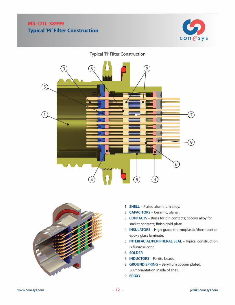
Typical ‘Pi’ Filter Construction
– –
1. SHELL – Plated aluminum alloy.
2. CAPACITORS – Ceramic, planar.
3. CONTACTS – Brass for pin contacts; copper alloy for
socket contacts; finish gold plate.
4. INSULATORS – High-grade thermoplastic/thermoset or
epoxy glass laminate.
5. INTERFACIAL/PERIPHERAL SEAL – Typical construction
is fluorosilicone.
6. SOLDER
7. INDUCTORS – Ferrite beads.
8. GROUND SPRING – Beryllium copper plated.
360º orientation inside of shell.
9. EPOXY
1 7
9
5
263
48
6
4

13www.conesys.com [email protected]– –
Note: Most leak testing is preceded by various levelsof temperature cycling
• MIL-STD-1344, Method 1008 Differential Pressure• MIL-STD-202, Method 112• 1 Meter Water Immersion at Various Durations
Sealed ConnectorsFor years filter connectors have been protectedfrom the elements with classic potting methodsand materials, both front and rear. The downfallis that following thermal cycling these connectorsallowed intrusion of moisture. Today’s sophisticatedapplications demand total prevention of any foreignmaterials inside the connector housing. Jerrik ismeeting these needs.
• Commercial and Military Aircraft• Extreme Temperature Environments• Ground BasedWarfighter Dunks• Aggressive PC Board Cleaning• Sprays & Aqueous Solutions
JERRIK offers:• Front Sealagainst outside of box environments
• Rear Sealagainst immersion and cleaning environments
• Bothcomplete protection of your box or filteredcircuitry
Show us your challenging environment and we’ll develop aSEALED connector SOLUTION for your application.

14www.conesys.com [email protected]– –
High voltage and lightning protection where it counts!
TVS ConnectorsThe ideal location for diodes to act as Transient VoltageSuppression devices for modern avionics boards and boxes isinside the interface connectors. When considering the higherdensity multi-pin connectors commonly used, finding theroom to package these diodes is a challenge.
Previous generations of ‘cord wood’ stacked leaded diodeconnectors double the size of a non TVS equivalent. Dependingon the screening level specified for the diodes, lead times andcosts for the diodes can be excessive. The solution to theseissues is packaging the diodes with the PCBs and treating thePCB assembly like a planar capacitor. By using this concept ofembedding the diodes with the PCBs the designer can makeuse of tighter packaging and off the shelf die to create aconnector that matches the size of EMI filter connectors.Consult with your Jerrik factory representative today and let usput lightning protectionWHERE IT COUNTS!
• Jerrik TVS packages are equivalent in sizeto standard EMI filter connectors
• Off the shelf devices support your project’sdelivery requirements
• Patent pending design provides requiredprotection for aircraft and helicopterapplications in smaller, lighter packaging
• Ready to meet and exceed requirements ofRTCA DO-160 lightning tests
• Proven, available lightning protection for‘all electric’ control systems

15www.conesys.com [email protected]
MIL-DTL-38999 Filter ConnectorsFeatures and Application
Series I, II, III, and IV
– –
MIL-DTL-38999 Filter Connectors
Incorporating all the mating dimensions, performance andenvironmental features of the military specification, Jerrik offersall four series of M38999 connectors filtered. See pages 18-26 foroutline dimension detail by series. Each connector is comprisedof pin or socket contacts, using the MIL-STD-1560 insertarrangements up to 128 contacts. While most projects requirereceptacle connectors, Jerrik can filter plug style connectors aswell. Consult with the factory for more details.
Series IMIL-DTL-38999 Series I is a bayonet coupling sub-miniatureconnector design offering high contact density ideal for small wiregauge signal pin applications. This series is environment resistingand the mating is “scoop-proof.” Pins are recessed in elongatedshells to prevent the possibility of bending contacts when plugsare scooped across the mating receptacles. Jerrik offers threestandard shell styles of receptacle, the front wall mount, the rearbox mount and the jam nut. Please see the Conesys/Aero-Electriccatalog, Military Specified Circular Connectors, for non-filtered plugmates. The Series I connectors offer over 50 insert arrangements,from MIL-STD-1560, to choose from. Contact sizes include 22D,20, 16, 12, 10 and 8. Jerrik customers can use the sizes 12, 10, or8 for power based on load requirements. Shells are aluminumbase material with electroless nickel or olive drab cadmium,standard. Consult the factory as Jerrik can provide other finishesas well as passivated stainless steel when necessary. The Series Ioffer closed entry socket inserts raised moisture barriers aroundeach pin for full environment resisting capability.
Series IIFeaturing the bayonet coupling system with a low profile design,the Series II are perfect where the external shell should be lowerand lighter weight.When filtered, Jerrik offers both the box mountand jam nut receptacles. Typically shells are aluminum basematerial with electroless nickel or olive drab cadmium, however,Jerrik can provide other finishes as well as passivated stainless
Series I Series II Series III Series IV
steel. Jerrik can offer over 50 insert arrangements for thisfamily, with contact sizes including 22D, 20, 16, 12. Seethe Aero-Electric catalog for plug style mates. While notscoop-proof this series does offer the closed-entry socketinserts and raised moisture barriers around each pin contactlike the series I. Jerrik offers all the shell key/keywaypositions found in the military specification.
Series IIIMIL-DTL-38999 Series III is the cylindrical connectordesigned for highest performance in general purpose andsevere environment applications. These connectors featurean improved ‘one-turn’ coupling system, utilizing a self-locking acme thread. Blunting the threads of both plug andreceptacle eliminates cross threading. Jerrik offers standarddesigns for both the wall mount and jam-nut receptacles.The Series III connectors offer insert arrangements commonto Series I, from MIL-STD-1560. Jerrik can offer more than50 insert arrangements for this family, with contact sizesincluding 22D, 20, 16, 12, 10 and 8. Jerrik customers can usethe sizes 12, 10, or 8 for power based on load. This familyoffers scoop-proof design, closed entry socket inserts andraised moisture barriers on the pin interfacial seals. Normallyplated aluminum, this series from Jerrik can also be firewallcapable by specifying stainless steel shells.
Series IVJerrik. Inc offers the receptacle style for filtered Series IVonly. The Series IV family makes a logical next generation toprevious 38999 families. The quarter turn mate and releaseare designed with rack and panel and warfighter applicationsin mind. Due to the scoop-proof design and the shellgrounding prior to engagement of contacts, reliability isvery high. The Series IV performs very well in settings wherevibration and shock are critical. Meanwhile, the nature ofthe mechanics of the quick lock coupling also offers goodEMI performance, further enhanced with our internal lowband pass filter.

16www.conesys.com [email protected]
MIL-DTL-38999 Series IJ991J (based on MS27468)Jam Nut Receptacle
– –
Page 5 Completed Part NumberPages 6–8 Insert ArrangementsPages 10–11 Electrical PerformancePage 9 Mechanical and Environmental PerformancePages 10–11 Filter Selection
O THREAD FLAT
S
[ DD
[ F [ J
.920 [23.37]
.910 [23.11]
.125 [3.18]MAX PANEL THICKNESS
.607 [15.41]REF.
D
1.400 [35.56]1.394 [35.41]
SEE WIRETERMINATIONDETAILSPAGE 4
M THREAD
Shell Size
� F � J K S � DD M O±.003 ±.08 Maximum ±.010 ±.25 ±.016 ±.40 ±.010 ±.25 Thread ±.005 ±.13
inch mm inch mm inch mm inch mm inch mm Class 2A inch mm
9 .570 14.48 .486 12.34 .109 2.77 1.062 26.97 1.188 30.18 .6875-24 UNEF .650 16.51
11 .698 17.73 .595 15.11 .109 2.77 1.250 31.75 1.375 34.93 .8125-20 UNEF .750 19.05
13 .848 21.54 .720 18.29 .109 2.77 1.375 34.93 1.500 38.10 1.0000-20 UNEF .937 23.80
15 .973 24.71 .876 22.25 .109 2.77 1.500 38.10 1.625 41.28 1.1250-18 UNEF 1.061 26.95
17 1.098 27.89 .986 25.04 .109 2.77 1.625 41.28 1.750 44.45 1.2500-18 UNEF 1.186 30.12
19 1.205 30.61 1.111 28.22 .140 3.56 1.812 46.02 1.938 49.23 1.3750-18 UNEF 1.311 33.30
21 1.330 33.78 1.236 31.39 .140 3.56 1.938 49.23 2.062 52.37 1.5000-18 UNEF 1.436 36.47
23 1.455 36.96 1.345 34.16 .140 3.56 2.062 52.37 2.188 55.58 1.6250-18 UNEF 1.561 39.65
25 1.580 40.13 1.454 36.93 .140 3.56 2.188 55.58 2.312 58.72 1.7500-18 UNS 1.686 42.82

17www.conesys.com [email protected]
MIL-DTL-38999 Series IJ991F (based on MS27466 and/or MS27496)
Wall Mount, Square Flange Receptacle
– –
Page 5 Completed Part NumberPages 6–8 Insert ArrangementsPages 10–11 Electrical PerformancePage 9 Mechanical and Environmental PerformancePages 10–11 Filter Selection
RR
S
4x [ P
[ F [ J
K
M1.400 [35.56]1.394 [35.41]
SEE WIRETERMINATIONDETAILSPAGE 4
Shell Size
� F � J M K S RR � P
+.000 +.00±.003 ±.08 Maximum –.005 –.13 ±.005 ±.13 ±.020 ±.50 Basic ±.005 ±.13
inch mm inch mm inch mm inch mm inch mm inch mm inch mm
9 .570 14.48 .486 12.34 .632 16.05 .090 2.29 .938 23.83 .719 18.26 .128 3.25
11 .698 17.73 .595 15.11 .632 16.05 .090 2.29 1.031 26.19 .812 20.62 .128 3.25
13 .848 21.54 .720 18.29 .632 16.05 .090 2.29 1.125 28.58 .906 23.01 .128 3.25
15 .973 24.71 .876 22.25 .632 16.05 .090 2.29 1.219 30.96 .969 24.61 .128 3.25
17 1.098 27.89 .986 25.04 .632 16.05 .090 2.29 1.312 33.32 1.062 26.97 .128 3.25
19 1.205 30.61 1.111 28.22 .632 16.05 .090 2.29 1.438 36.53 1.156 29.36 .128 3.25
21 1.330 33.78 1.236 31.39 .602 15.29 .120 3.05 1.562 39.67 1.250 31.75 .128 3.25
23 1.455 36.96 1.345 34.16 .602 15.29 .120 3.05 1.688 42.88 1.375 34.93 .147 3.73
25 1.580 40.13 1.454 36.93 .602 15.29 .120 3.05 1.812 46.02 1.500 38.10 .147 3.73

18www.conesys.com [email protected]
MIL-DTL-38999 Series IJ991B (based on MS27505)Back Panel, Box Mount, Square Flange Receptacle
– –
Page 5 Completed Part NumberPages 6–8 Insert ArrangementsPages 10–11 Electrical PerformancePage 9 Mechanical and Environmental PerformancePages 10–11 Filter Selection
RR
S
4x [ P
[ F [ J
K
M1.400 [35.56]1.394 [35.41]
SEE WIRETERMINATIONDETAILSPAGE 4
Shell Size
� F � J M K S RR � P
+.000 +.00±.003 ±.08 Maximum –.005 –.13 ±.005 ±.13 ±.020 ±.50 Basic ±.005 ±.13
inch mm inch mm inch mm inch mm inch mm inch mm inch mm
9 .570 14.48 .486 12.34 .820 20.83 .090 2.29 .938 23.83 .719 18.26 .128 3.25
11 .698 17.73 .595 15.11 .820 20.83 .090 2.29 1.031 26.19 .812 20.62 .128 3.25
13 .848 21.54 .720 18.29 .820 20.83 .090 2.29 1.125 28.58 .906 23.01 .128 3.25
15 .973 24.71 .876 22.25 .820 20.83 .090 2.29 1.219 30.96 .969 24.61 .128 3.25
17 1.098 27.89 .986 25.04 .820 20.83 .090 2.29 1.312 33.32 1.062 26.97 .128 3.25
19 1.205 30.61 1.111 28.22 .820 20.83 .090 2.29 1.438 36.53 1.156 29.36 .128 3.25
21 1.330 33.78 1.236 31.24 .790 20.07 .120 3.05 1.562 39.67 1.250 31.75 .128 3.25
23 1.455 36.96 1.345 34.16 .790 20.07 .120 3.05 1.688 42.88 1.375 34.93 .147 3.73
25 1.580 40.13 1.454 36.93 .790 20.07 .120 3.05 1.812 46.02 1.500 38.10 .147 3.73

19www.conesys.com [email protected]
MIL-DTL-38999 Series IIJ992J (based on MS27474)
Jam Nut Receptacle
– –
Page 5 Completed Part NumberPages 6–8 Insert ArrangementsPages 10–11 Electrical PerformancePage 9 Mechanical and Environmental PerformancePages 10–11 Filter Selection
NTHREAD FLAT
[ Q
S
[ F [ J
C1.061 [26.95]
.109 [2.77] MAX PANEL THICKNESS
M THREAD
SHELL AVAILABLEWITH OR WITHOUTACCESSORY HARDWARETHREAD
.106 [2.69]
.084 [2.13]
SEE WIRETERMINATIONDETAILSPAGE 4
Shell Size
� F � J C S � Q M N±.003 ±.08 Maximum ±.003 ±.08 ±.010 ±.25 ±.010 ±.25 Thread ±.003 ±.08
inch mm inch mm inch mm inch mm inch mm 2A inch mm
8 .471 11.96 .486 12.34 .438 11.13 1.250 31.75 1.375 34.93 .875-20 UNEF .814 20.68
10 .588 14.94 .595 15.11 .438 11.13 1.375 34.93 1.500 38.10 1.000-20 UNEF .938 23.83
12 .748 19.00 .720 18.29 .438 11.13 1.500 38.10 1.625 41.28 1.125-18 UNEF 1.062 26.97
14 .873 22.17 .876 22.25 .438 11.13 1.625 41.28 1.750 44.45 1.250-18 UNEF 1.187 30.15
16 .998 25.35 .986 25.04 .438 11.13 1.781 45.24 1.938 49.23 1.375-18 UNEF 1.317 33.45
18 1.123 28.52 1.111 28.22 .438 11.13 1.890 48.01 2.016 51.21 1.500-18 UNEF 1.437 36.50
20 1.248 31.70 1.236 31.39 .464 11.79 2.016 51.21 2.141 54.38 1.625-18 UNEF 1.562 39.67
22 1.373 34.87 1.345 34.16 .464 11.79 2.140 54.36 2.265 57.53 1.750-18 UNS 1.687 42.85
24 1.498 38.05 1.454 36.93 .464 11.79 2.265 57.53 2.390 60.71 1.875-16 UN 1.812 46.02

20www.conesys.com [email protected]
MIL-DTL-38999 Series IIJ992B (based on MS27508 and/or MS27497)Back Panel, Wall and Box Mount, Square Flange Receptacle
– –
Page 5 Completed Part NumberPages 6–8 Insert ArrangementsPages 10–11 Electrical PerformancePage 9 Mechanical and Environmental PerformancePages 10–11 Filter Selection
RR
S
4x [ T
[ F[ AB [ J
.322 [8.18]
.317 [8.05]
1.061 [26.95]
.447 [11.35]
.442 [11.23]
.069 [1.75]
.058 [1.47]
SEE WIRETERMINATIONDETAILSPAGE 4
Shell Size
� F � J S RR � T � AB±.003 ±.08 Maximum ±.005 ±.13 Basic ±.005 ±.13 Maximum
inch mm inch mm inch mm inch mm inch mm inch mm
8 .471 11.96 .486 12.34 .808 20.52 .594 15.09 .120 3.05 .547 13.89
10 .588 14.94 .595 15.11 .934 23.72 .719 18.26 .120 3.05 .672 17.07
12 .748 19.00 .720 18.29 1.027 26.09 .812 20.62 .120 3.05 .844 21.44
14 .873 22.17 .876 22.25 1.121 28.47 .906 23.01 .120 3.05 .969 24.61
16 .998 25.35 .986 25.04 1.214 30.84 .969 24.61 .120 3.05 1.094 27.79
18 1.123 28.52 1.111 28.22 1.308 33.22 1.062 26.97 .120 3.05 1.219 30.96
20 1.248 31.70 1.236 31.39 1.433 36.40 1.156 29.36 .120 3.05 1.344 34.14
22 1.373 34.87 1.345 34.16 1.558 39.57 1.250 31.75 .120 3.05 1.469 37.31
24 1.498 38.05 1.454 36.93 1.683 42.75 1.375 34.93 .147 3.73 1.594 40.49

21www.conesys.com [email protected]
MIL-DTL-38999 Series IIIJ993W (based on 38999/20)
Wall Mount, Square Flange Receptacle
– –
Page 5 Completed Part NumberPages 6–8 Insert ArrangementsPages 10–11 Electrical PerformancePage 9 Mechanical and Environmental PerformancePages 10–11 Filter Selection
S
R1
R2
PP
P
[ B
A THREADSEE WIRETERMINATIONDETAILSPAGE 4
35.81 [1.410]
V W
ShellSize
A � B S R1 R2 P PP V WThread Maximum ±.010 ±.25 Basic Basic ±.005 ±.13 ±.005 ±.13 Maximum
0.1P-0.3L-2A inch mm inch mm inch mm inch mm inch mm inch mm inch mm inch mm
9 .6250 0.486 12.34 0.937 23.80 0.719 18.26 0.594 15.09 0.128 3.25 0.216 5.49 0.82 20.83 .098/.083 2.50/2.10
11 .7500 0.595 15.11 1.031 26.20 0.812 20.62 0.719 18.26 0.128 3.25 0.194 4.93 0.82 20.83 .098/.083 2.50/2.10
13 .8750 0.72 18.29 1.126 28.60 0.906 23.01 0.812 20.62 0.128 3.25 0.194 4.93 0.82 20.83 .098/.083 2.50/2.10
15 1.0000 0.876 22.25 1.220 31.00 0.969 24.61 0.906 23.01 0.128 3.25 0.173 4.39 0.82 20.83 .098/.083 2.50/2.10
17 1.1875 0.986 25.04 1.311 33.30 1.062 26.97 0.969 24.61 0.128 3.25 0.194 4.93 0.82 20.83 .098/.083 2.50/2.10
19 1.2500 1.111 28.22 1.437 36.50 1.156 29.36 1.062 26.97 0.128 3.25 0.194 4.93 0.82 20.83 .098/.083 2.50/2.10
21 1.3750 1.236 31.39 1.563 39.70 1.250 31.75 1.156 29.36 0.128 3.25 0.194 4.93 0.79 20.07 .125/.083 3.20/2.10
23 1.5000 1.345 34.16 1.689 42.90 1.375 34.93 1.250 31.75 0.154 3.91 0.242 6.15 0.79 20.07 .125/.083 3.20/2.10
25 1.6250 1.454 36.93 1.811 46.00 1.5 38.10 1.375 34.93 0.154 3.91 0.242 6.15 0.79 20.07 .125/.083 3.20/2.10

22www.conesys.com [email protected]
MIL-DTL-38999 Series IIIJ993J (based on 38999/24)Jam Nut Receptacle
– –
Page 5 Completed Part NumberPages 6–8 Insert ArrangementsPages 10–11 Electrical PerformancePage 9 Mechanical and Environmental PerformancePages 10–11 Filter Selection
BTHREAD FLAT
S
[ A
35.81 [1.410]
22.58 [.889]22.20 [.874] W
[ F
BB THREAD
G THREAD
SEE WIRETERMINATIONDETAILSPAGE 4
Shell Size
BB � F W S � A G BThread Maximum ±.005 ±.13 ±.005 ±.13 ±.005 ±.13 Thread ±.004 ±.10
-01P-0.3L-2A inch mm inch mm inch mm inch mm x1.0-6g 0.100R inch mm
9 .6250 .486 12.34 .100 2.54 1.062 27.00 1.188 30.20 M17 .650 16.53
11 .7500 .595 15.11 .100 2.54 1.250 31.80 1.375 34.90 M20 .750 19.07
13 .8750 .720 18.29 .100 2.54 1.375 34.90 1.500 38.10 M25 .937 23.82
15 1.0000 .876 22.25 .100 2.54 1.500 38.10 1.625 41.30 M28 1.062 26.97
17 1.1875 .986 25.04 .100 2.54 1.625 41.30 1.750 44.50 M32 1.187 30.15
19 1.2500 1.111 28.22 .130 3.30 1.812 46.00 1.938 49.20 M35 1.312 33.32
21 1.3750 1.236 31.39 .130 3.30 1.938 49.20 2.062 52.40 M38 1.437 36.50
23 1.5000 1.345 34.16 .130 3.30 2.062 52.40 2.188 55.60 M41 1.562 39.67
25 1.6250 1.454 36.93 .130 3.30 2.188 55.60 2.312 58.70 M44 1.687 42.85

23www.conesys.com [email protected]
MIL-DTL-38999 Series IVJ994W (based on 38999/40)
Wall Mount, Square Flange Receptacle
– –
Page 5 Completed Part NumberPages 6–8 Insert ArrangementsPages 10–11 Electrical PerformancePage 9 Mechanical and Environmental PerformancePages 10–11 Filter Selection
RR
S
4x [ P
[ J [ F
28.19 [1.110]27.69 [1.090]
W0.5 [.020]
36.14 [1.423] SEE WIRETERMINATIONDETAILSPAGE 4
Shell Size
� J � F W S RR � P±.003 ±.08 Maximum ±.005 ±.25 ±.005 ±.13 ±.005 ±.13 ±.005 ±.13
inch mm inch mm inch mm inch mm inch mm inch mm
11 .506 12.85 .595 15.11 .093 2.35 1.375 34.93 .812 20.62 .129 3.28
13 .631 16.02 .720 18.29 .093 2.35 1.500 38.10 .906 23.02 .129 3.28
15 .756 19.20 .876 22.25 .093 2.35 1.625 41.28 .969 24.62 .129 3.28
17 .882 22.40 .986 25.04 .093 2.35 1.750 44.45 1.062 26.98 .129 3.28
19 1.006 25.55 1.111 28.22 .093 2.35 1.938 49.23 1.156 29.36 .129 3.28
21 1.131 28.72 1.236 31.39 .124 3.15 2.062 52.37 1.250 31.76 .129 3.28
23 1.256 31.90 1.345 34.16 .124 3.15 2.188 55.58 1.375 34.92 .150 3.81
25 1.381 35.08 1.454 36.93 .124 3.15 2.312 58.72 1.500 38.10 .150 3.81

24www.conesys.com [email protected]
MIL-DTL-38999 Series IVJ994J (based on 38999/44)Jam Nut Receptacle
– –
Page 5 Completed Part NumberPages 6–8 Insert ArrangementsPages 10–11 Electrical PerformancePage 9 Mechanical and Environmental PerformancePages 10–11 Filter Selection
BTHREAD FLAT
S
[ A
[ J [ F
36.14 [1.423]
2.54 [.100]2.03 [.080]
3.20 [.126] MAX PANEL THICKNESS28.19 [1.110]27.69 [1.090]
G THREAD
SEE WIRETERMINATIONDETAILSPAGE 4
Shell Size
� J � F S � A G B±.003 ±.08 ±.005 ±.13 ±.005 ±.13 ±.005 ±.13 Thread ±.004 ±.08
inch mm inch mm inch mm inch mm 1.0-6g±0.100R inch mm
11 .506 12.85 .584 14.83 1.374 34.90 1.500 38.10 M25 .938 23.83
13 .631 16.02 .702 17.83 1.500 38.10 1.622 41.20 M28 1.062 26.97
15 .756 19.20 .860 21.84 1.622 41.20 1.748 44.40 M31 1.188 30.18
17 .882 22.40 .978 24.84 1.779 45.20 1.937 49.20 M34 1.318 33.48
19 1.006 25.55 1.0966 27.84 1.889 48.00 2.016 51.20 M38 1.438 36.53
21 1.131 28.72 1.214 30.84 2.016 51.20 2.138 54.30 M41 1.562 39.67
23 1.256 31.90 1.332 33.83 2.138 54.30 2.264 57.50 M44 1.688 42.88
25 1.381 35.08 .1450 36.83 2.264 57.50 2.390 60.70 M47 1.812 46.02
25www.conesys.com [email protected]
MIL-DTL-26482 Filter ConnectorsFeatures and Application
Series 2
– –
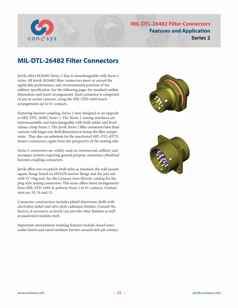
MIL-DTL-26482 Filter Connectors
Jerrik offers M26482 Series 2 that is interchangeable with Series 1styles. All Jerrik M26482 filter connectors meet or exceed theapplicable performance and environmental portions of themilitary specification. See the following pages for standard outlinedimensions and insert arrangements. Each connector is comprisedof pin or socket contacts, using the MIL-STD-1669 insertarrangements up to 61 contacts.
Featuring bayonet coupling, Series 2 were designed as an upgradeto MIL-DTL-26482 Series 1. The Series 2 mating interfaces areintermountable and interchangeable with both solder and frontrelease crimp Series 1. The Jerrik Series 2 filter connectors have fixedcontacts with larger rear shell dimensions to house the filter compo-nents. They also can substitute for the inactivated MIL-DTL-83723Series I connectors, again from the perspective of the mating side.
Series 2 connectors are widely used on commercial, military andaerospace systems requiring general purpose, miniature cylindricalbayonet coupling connectors.
Jerrik offers two receptacle shell styles as standard, the wall mountsquare flange based on MS3470 narrow flange and the jam nutwith ‘O’-ring seal. See the Conesys Aero-Electric catalog for theplug style mating connectors. This series offers insert arrangementsfrom MIL-STD-1669 in patterns from 2 to 61 contacts. Contactsizes are 20, 16 and 12.
Connector construction includes plated aluminum shells withelectroless nickel and olive drab cadmium finishes. Consult thefactory, if necessary, as Jerrik can provide other finishes as wellas passivated stainless steel.
Important environment resisting features include closed entrysocket inserts and raised moisture barriers around each pin contact.

26www.conesys.com [email protected]
MIL-DTL-26482 Series 2Part Number DevelopmentCircular Filter Connectors
Jerrik Part Number Development
– –
Filter J 82 2 W S B N 6 A P A N
Shell Configuration
82 = MIL-DTL-26482
Series
2
Shell Style
W = Wall Mount Receptacle (Narrow based on MS 3470)
J = Jam Nut Receptacle
Termination Type
S = Solder Cup
P = PC Tail
C = Crimp
W = Wire Wrap
Shell Sizes
A=8, B =10, C=12, D=14, E=16, F=18, G=20, H=22, J=24
Shell Finish
N = Electroless Nickel
O = Olive Drab Cadmium Nickel
P = Passivated Stainless Steel
D = Electro-deposited Nickel over Stainless Steel
Y = Yellow Chromate Cadmium
Contact Arrangement or Number of Contacts
See pages 27–28
Filter Characteristics
A = PL, B = PM, C = PT, D = PH, E = PVH, F = CL, G = CM, H = CT, J = CH, K = CVH (see pages 10–11)
Contact Type
P = Pin
S = Socket
Modifier
A = N/A
B = #4-40 Clinch Nut
C = #6-32 Clinch Nut
D = #4-40 Helicoil
E = #6-32 Helicoil
Polarization
N,W, X, Y, Z, A, B, C, or D

27www.conesys.com [email protected]– –
MIL-STD-1669Insert Arrangement (Pin Front View)
for MIL-DTL-26482 Series 2 Connectors
Insert Arrangement Views
A
B
CABA
B C
D A
BC
A
B
C AB
CD
E
F
AB
G
CD
E
F A
B
C
A
H B
CD
E
F
G
A B
C
DEF
G
H
JK
A
B
C
D
AB
CD
E
A
B
C
D
E
F
G
H
J
A
B
C
DE
F
G
M
H
J
K
L
A
B
R C
D
EF
G
H
J
K
L
M
N
P
A
B
C
D
EFG
H
J
K
L
M N
P
RS
T U
A B
C
D
E
FGH
J
K
L
M
N P
R
ST
U V
A
B
C
DE
F
G
H
A
B
C
D
E
F
G
H
J
K
L
M
N P
A
B
C
D
E
FGH
J
K
L
M
NP
RS
T
UV
W
X
Y
Z
AB
C
D
E
F
GHJ
K
L
M
N
P
R
S T
U
V
WX
Y
Z
a b
c
A
B
C
DE
F
G
H
A
B
C
DE
G
H
J
K
L
F
AB
C
D
E
F
GHJ
K
L
M
N
P
RS
T
U
V
W
XY
Z
a
b
c
d
e
fg
AB
C
D
E
F
G
HJK
L
M
N
P
R
ST
UV
W
X
YZa
b
c
d
e
f
g
h
J
A
B
C
D
EF
G
H
J
K
L
M
N
PR
S
8-33 # 20
8-22 # 20
8-44 # 20
8-333 # 20
8-983 # 20
10-66 # 20
10-7*7 # 20
12-33 # 16
12-88 # 20
12-1010 # 20
14-44 # 12
14-55 # 16
14-95 # 20, 4 # 12
14-124 # 16, 8 # 20
14-151 # 16, 14 # 20
14-1818 # 20
14-1919 # 20
16-88 # 16
16-148 # 20, 6 # 12
16-231 # 16, 22 # 20
16-2626 # 20
18-88 # 12
18-1111 # 16
20-1616 # 16
18-3232 # 20
18-301 # 16, 29 # 20
AB
14-2*2 # 12
*Not MIL-STD-1669 layout.

28www.conesys.com [email protected]– –
MIL-STD-1669Insert Arrangement (Pin Front View)for MIL-DTL-26482 Series 2 Connectors
Insert Arrangement Views
A
B
C
D
EF
G
H
J
K
LM
N
P
R
ST
U
V
W X
Y
Z
a
20-2424 # 20
AB
C
D
E
F
G
H
JKL
M
N
P
R
S
T
UV
W
XY
Z
a
b
cde
f
g
h
Jk
m
nP
r
i
q
20-392 # 16, 37 # 20
20-4141 # 20
A
B
C
D
E
FGH
J
K
L
M
N
P
R
S
TU
V
W
X
22-2121 # 16
A
B
C
D
EF
G
H
J
K
L
M
22-1212 # 12
a
b
c
d
ef
g
H
j
k
m
n
Pr
s
t
AB
C
D
E
F
GH
JK
LMN
R
S
T
U
V
W
XY
Z
P
i
q
22-4114 # 16, 27 # 20
AB
C
D
E
F
GH
JKL
M
N
P
R
ST
UV
WX
Y
Zl
a
b
c
de
fg
h
k
m
np
r
s
t
uv
wx
y
z
i
qAABB
CC
DDEE
FF
GGHH
22-5555 # 20
A B
C
D
E
F
G
H
JK
LMN
P
R
S
T
U
V
WX
Y Z
a
b
c
d
ef
g
h
j
22-956 # 12, 26 # 20
A B
C
D
E
FGH
J
K
L
M
N P
R
ST
U V
24-1919 # 12
A
B
C
D
E
FG
H
J
K
L
M
N
P
R
S
TU
V
W
X
Y
Z
a
b
cd
e
f
g
Q
24-3131 # 16
AB
C
D
E
F
G
H
J
KL
MNP
R
S
T
U
V
W
X
YZ
AABB
CC
DD
EE
FF
GGHH
JJ
LL
KKMM
NN
PP
a bc
d
e
f
g
h
jkmn
p
r
s
tu
vw
x
y
z
i
q
24-6161 # 20
AB
C
D
E
F
G
H
JK
LM
N
P
R
S
T
U
VW
XY
Z
a
b
c
de
f
g
h
jk
m
n
p
r
si
q
t

29www.conesys.com [email protected]
MIL-DTL-26482 Series 2J822W (based on MS3470)
Wall Mount, Square Flange Receptacle
– –
Page 26 Completed Part NumberPages 27–28 Insert ArrangementsPages 10–11 Electrical PerformancePage 9 Mechanical and Environmental PerformancePages 10–11 Filter Selection
F
E
4x [ G
[ A [ B
L
D
C*
SEE WIRETERMINATIONDETAILSPAGE 4
ShellSize
� A � B C D E F � G L±.003 ±.08 ±.003 ±.08 ±.005 ±.13 ±.005 ±.13 ±.005 ±.13 Basic ±.005 ±.13 ±.005 ±.13
inch mm inch mm inch mm inch mm inch mm inch mm inch mm inch mm
8 .471 11.96 .495 12.57 .457 11.61 .073 1.85 .823 20.90 .594 15.09 .120 3.05 1.210 30.73
10 .588 14.94 .625 15.87 .457 11.61 .073 1.85 .949 24.10 .719 18.26 .120 3.05 1.210 30.73
12 .748 19.00 .745 18.92 .457 11.61 .073 1.85 1.042 26.46 .812 20.62 .120 3.05 1.210 30.73
14 .873 22.17 .870 22.10 .457 11.61 .073 1.85 1.136 28.85 .906 23.01 .120 3.05 1.210 30.73
16 .998 25.35 .995 25.27 .457 11.61 .073 1.85 1.229 31.22 .969 24.61 .120 3.05 1.210 30.73
18 1.123 28.52 1.058 26.87 .457 11.61 .073 1.85 1.323 33.60 1.062 26.97 .120 3.05 1.210 30.73
20 1.248 31.70 1.183 30.05 .582 14.78 .105 2.67 1.448 36.78 1.156 29.36 .120 3.05 1.270 32.26
22 1.373 34.87 1.308 33.22 .582 14.78 .105 2.67 1.573 39.95 1.250 31.75 .120 3.05 1.270 32.26
24 1.498 38.05 1.433 36.40 .615 15.62 .105 2.67 1.698 43.13 1.375 34.93 .147 3.73 1.270 32.26

30www.conesys.com [email protected]– –
Page 26 Completed Part NumberPages 27–28 Insert ArrangementsPages 10–11 Electrical PerformancePage 9 Mechanical and Environmental PerformancePages 10–11 Filter Selection
MIL-DTL-26482 Series 2J822J (based on MS3474)Jam Nut Receptacle
E
HTHREAD FLAT
[ F
[ A [ B
C*D
L SEE WIRETERMINATIONDETAILSPAGE 4
ShellSize
� A � B C D E � F G H L
Thread±.003 ±.08 ±.003 ±.08 ±.003 ±.08 ±.003 ±.08 ±.003 ±.08 ±.005 ±.13 UNEF-2A ±.003 ±.08 ±.003 ±.08
inch mm inch mm inch mm inch mm inch mm inch mm inch inch mm inch mm
8 .471 11.96 .495 12.57 .690 17.53 .108 2.74 0.939 23.85 1.062 26.97 .5625-24 .525 13.34 1.210 30.73
10 .588 14.94 .625 15.87 .700 17.78 .108 2.74 1.062 26.97 1.187 30.15 .6875-24 .650 16.51 1.210 30.73
12 .748 19.00 .745 18.92 .690 17.53 .108 2.74 1.25 31.75 1.375 34.93 .875-20 .813 20.65 1.210 30.73
14 .873 22.17 .870 22.10 .690 17.53 .108 2.74 1.375 34.93 1.500 38.10 1.000-20 .937 23.80 1.210 30.73
16 .998 25.35 .995 25.27 .690 17.53 .108 2.74 1.500 38.10 1.625 41.28 1.125-18 1.061 26.95 1.210 30.73
18 1.123 28.52 1.058 26.87 .690 17.53 .108 2.74 1.625 41.28 1.75 44.45 1.250-18 1.186 30.12 1.210 30.73
20 1.248 31.70 1.183 30.05 .760 19.30 .143 3.63 1.812 46.02 1.938 49.23 1.375-18 1.311 33.30 1.270 32.26
22 1.373 34.87 1.308 33.22 .760 19.30 .143 3.63 1.938 49.23 2.062 52.37 1.500-18 1.436 36.47 1.270 32.26
24 1.498 38.05 1.433 36.40 .760 19.30 .143 3.63 2.062 52.37 2.187 55.55 1.625-18 1.561 39.65 1.270 32.26

31www.conesys.com [email protected]– –
MIL-DTL-24308 D-Sub and MIL-DTL-83513 Micro-DPart Number Development
Jerrik Part Number Development
Filter J 08 5 P S 3 N 25 A P A
Shell Configuration
08 = MIL-DTL-24308
13 = MIL-DTL-83513
Series
5 = NA
Shell Style
P = Plug (Pin)
R = Receptacle (Socket)
Termination Type
S = Solder Cup
P = PC Tail
C = Crimp
W = Wire Wrap
T = InsulatedWire
U = UninsulatedWire
Shell Sizes
1, 2, 3, 4, 5, or 6
Shell Finish
N = Electroless Nickel
G = Gold
P = Passivated Stainless Steel
D = Electro-deposited Nickel over Stainless Steel
Y = Yellow Chromate Cadmium
Contact Arrangement or Number of Contacts
9, 15, 21, 25, 26, 31, 37, 44, 50, 62, 78, or 104
Filter Characteristics
A = PL, B = PM, C = PT, D = PH, E = PVH, F = CL, G = CM, H = CT, J = CH, K = CVH
Contact Type
P = Pin (Plug)
S = Socket (Receptacle)
Modifier
A = N/A
B = #4-40 Clinch Nut
C = #6-32 Clinch Nut
D = #4-40 Helicoil
E = #6-32 Helicoil
32www.conesys.com [email protected]– –
MIL-DTL-24308 Filter ConnectorsFeatures and ApplicationPlug and Receptacle
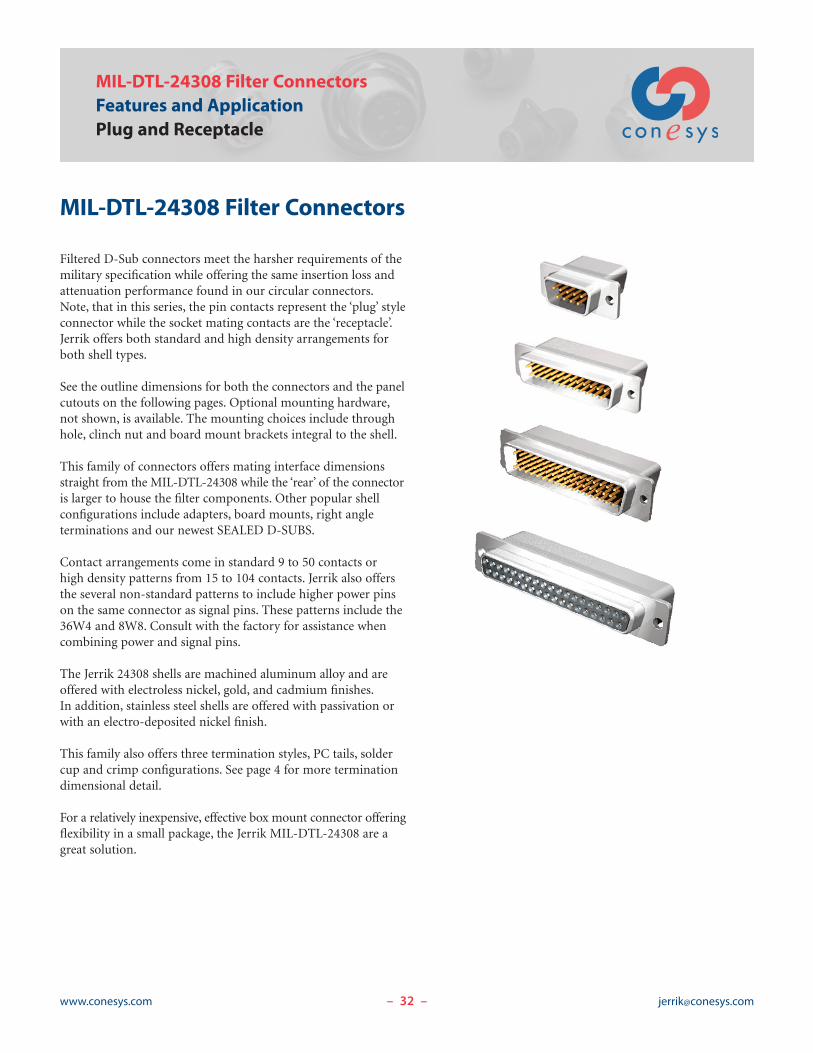
MIL-DTL-24308 Filter Connectors
Filtered D-Sub connectors meet the harsher requirements of themilitary specification while offering the same insertion loss andattenuation performance found in our circular connectors.Note, that in this series, the pin contacts represent the ‘plug’ styleconnector while the socket mating contacts are the ‘receptacle’.Jerrik offers both standard and high density arrangements forboth shell types.
See the outline dimensions for both the connectors and the panelcutouts on the following pages. Optional mounting hardware,not shown, is available. The mounting choices include throughhole, clinch nut and board mount brackets integral to the shell.
This family of connectors offers mating interface dimensionsstraight from the MIL-DTL-24308 while the ‘rear’ of the connectoris larger to house the filter components. Other popular shellconfigurations include adapters, board mounts, right angleterminations and our newest SEALED D-SUBS.
Contact arrangements come in standard 9 to 50 contacts orhigh density patterns from 15 to 104 contacts. Jerrik also offersthe several non-standard patterns to include higher power pinson the same connector as signal pins. These patterns include the36W4 and 8W8. Consult with the factory for assistance whencombining power and signal pins.
The Jerrik 24308 shells are machined aluminum alloy and areoffered with electroless nickel, gold, and cadmium finishes.In addition, stainless steel shells are offered with passivation orwith an electro-deposited nickel finish.
This family also offers three termination styles, PC tails, soldercup and crimp configurations. See page 4 for more terminationdimensional detail.
For a relatively inexpensive, effective box mount connector offeringflexibility in a small package, the Jerrik MIL-DTL-24308 are agreat solution.

33www.conesys.com [email protected]– –
Page 31 Completed Part Number(See Table) Insert ArrangementsPages 10–11 Electrical PerformancePage 9 Mechanical and Environmental PerformancePages 10–11 Filter Selection
MIL-DTL-24308 D-SubJ085P/R
Standard Dimensions
ShellSize
StandardLayout
#20 Contact
High DensityLayout
#22D Contact
A B B C D D E F G
for pin for socket for pin for socket±.015 ±.38 ±.005 ±.13 ±.005 ±.13 ±.005 ±.13 ±.005 ±.13 ±.005 ±.13 ±.015 ±.38 ±.010 ±.25 ±.010 ±.25
inch mm inch mm inch mm inch mm inch mm inch mm inch mm inch mm inch mm
1 9 15 1.213 30.81 .666 16.92 .643 16.33 .984 24.99 .329 8.36 .309 7.85 .494 12.55 .759 19.28 .422 10.72
2 15 26 1.541 39.14 .994 25.25 .971 24.66 1.312 33.32 .329 8.36 .309 7.85 .494 12.55 1.083 27.51 .422 10.72
3 25 44 2.088 53.04 1.534 38.96 1.511 38.38 1.852 47.04 .329 8.36 .309 7.85 .494 12.55 1.625 41.28 .422 10.72
4 37 62 2.729 69.32 2.182 55.42 2.159 54.84 2.500 63.50 .329 8.36 .309 7.85 .494 12.55 2.272 57.71 .422 10.72
5 50 78 2.635 66.93 2.079 52.81 2.064 52.43 2.406 61.11 .441 11.20 .423 10.74 .605 15.37 2.178 55.32 .534 13.56
6 – 104 2.729 69.32 2.212 56.18 2.189 55.60 2.500 63.50 .503 12.78 .485 12.32 .668 16.97 2.302 58.47 .596 15.14
A
BPBS
C
E DPDS
11°/9°
.236/.229PIN CONTACTS
.070/.055
.238/.228SOCKET CONTACTS
.615/.603
F
G
4xR.090/.062
2x [ .133/.123#4-40 CLINCH NUTS ALSO AVAILABLE
FRONT VIEW
REAR VIEW
SEE WIRETERMINATIONDETAILSPAGE 4

34www.conesys.com [email protected]– –
10°
C
.122/.1182x [
[ .122/.118
A
EJ RADIUS(4 PLACES)
FULL RADIUS
FRONT MOUNTING
REAR MOUNTING
OPTIONAL CUTOUT (for Rear Mounting)
C
STANDARD CUTOUT (Front or Rear Mount)
MIL-DTL-24308 D-SubJ085P/RMounting Dimensions
D-Subminiature Connectors
ShellSize
A A C C E E J J
Front Mount Rear Mount Front Mount Rear Mount Front Mount Rear Mount Front Mount Rear Mount±.005 ±.13 ±.005 ±.13 ±.005 ±.13 ±.005 ±.13 ±.005 ±.13 ±.005 ±.13 ±.005 ±.13 ±.005 ±.13
inch mm inch mm inch mm inch mm inch mm inch mm inch mm inch mm
1 .833 21.16 .806 20.47 .984 24.99 .984 24.99 .485 12.32 .449 11.40 .065 1.65 .132 3.35
2 1.161 29.49 1.134 28.80 1.312 33.32 1.312 33.32 .485 12.32 .449 11.40 .065 1.65 .132 3.35
3 1.700 43.18 1.674 42.52 1.852 47.04 1.852 47.04 .485 12.32 .449 11.40 .065 1.65 .132 3.35
4 2.349 59.66 2.326 59.08 2.500 63.50 2.500 63.50 .485 12.32 .449 11.40 .065 1.65 .132 3.35
5 2.254 57.25 2.218 56.34 2.406 61.11 2.406 61.11 .593 15.06 .555 14.10 .065 1.65 .132 3.35
6 2.372 60.25 2.250 57.15 2.500 63.50 2.500 63.50 .655 16.64 .617 15.67 .065 1.65 .132 3.35
35www.conesys.com [email protected]– –
.127
.097
.150 MIN
.725
.705
.150 MIN
.725
.705
.127
.097
.127
.097.328.308
.127
.097
.150 MIN
.127
.097
.328
.308
.122
.102
.150 MIN
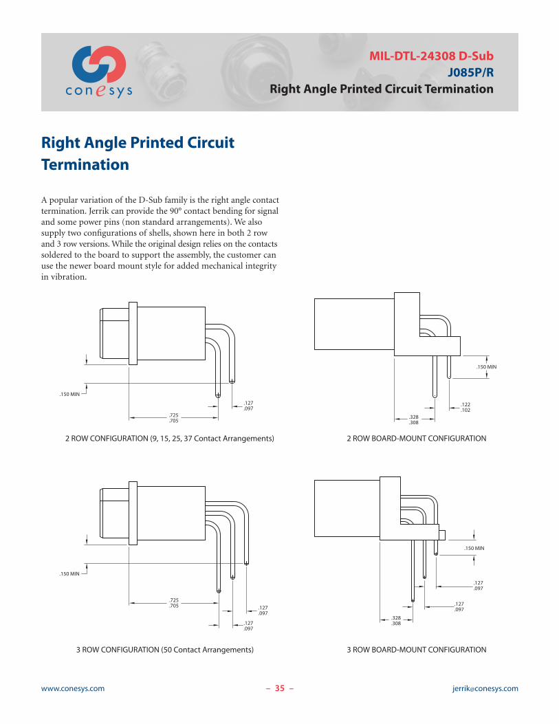
2 ROW CONFIGURATION (9, 15, 25, 37 Contact Arrangements) 2 ROW BOARD-MOUNT CONFIGURATION
3 ROW CONFIGURATION (50 Contact Arrangements) 3 ROW BOARD-MOUNT CONFIGURATION
MIL-DTL-24308 D-SubJ085P/R
Right Angle Printed Circuit Termination
Right Angle Printed CircuitTermination
A popular variation of the D-Sub family is the right angle contacttermination. Jerrik can provide the 90° contact bending for signaland some power pins (non standard arrangements). We alsosupply two configurations of shells, shown here in both 2 rowand 3 row versions.While the original design relies on the contactssoldered to the board to support the assembly, the customer canuse the newer board mount style for added mechanical integrityin vibration.

36www.conesys.com [email protected]– –
MIL-DTL-83513 Micro-DFeatures and ApplicationPlug and Receptacle
MIL-DTL-83513 Filter Connectors
Offering space savings over the more popular D-Sub connectors,these filtered Micro-D connectors meet the harsher requirementsof the military specification while offering the same insertion lossand attenuation performance found in our circular connectors.Note, that in this series, the pin contacts represent the ‘plug’ styleconnector while the socket mating contacts are the ‘receptacle’.Jerrik offers a full complement of shell sizes and arrangementsfor both shell types. See the outline dimensions for both on thefollowing pages.
Like the D-Sub family, the shell size varies based on the numberof contacts specified. This family offers six arrangements from9 to 37 pins. Jerrik offers a variety of contact tail lengths that arespecified by the customer. The bases for the standard JerrikMicro-D family are the M83513/03 pin and M83513/04 socketconnectors, pre-wired with straight wire tails. Other higher pincount configurations are available but require special packaging.Please consult the factory with your requirements. In addition tostraight wire tails, the customer can also request pig tail cableterminations for longer cable stretches inside their next levelassembly.
High quality dielectric materials include a Liquid Crystal Polymerinsulator over the pins. The interfacial seals are fluoro-siliconerubber. Contact materials are copper and beryllium copper withgold over nickel plating for pins and copper alloy with gold overnickel plating for sockets. Current rating for these very highdensity connectors is 3 amps maximum. The insulation resistanceis 5000 Meg-ohms at 500 volts DC.
Plated aluminum alloy shells and stainless steel shells are offeredwith various finish detail, just like the D-Sub family. Shell optionsalso include board mount styles and hex nut mounting accessories.Let us know your needs.
Advantages of this family include space savings and enhancedEMI protection via shell design and the twist pin male contact.This style of pin offers reliability of continuous contact in severevibration and temperature environments while maintaining lowelectrical resistance for mated pairs.

37www.conesys.com [email protected]– –
A
E
FB
Pin Plug shown with ‘Pi’ !lter shell length
D
.186
.180
.600 MAX
C
F
E
B
A
Socket Receptacle shown with ‘C’ !lter shell length
.429 MAX
.198
.192
.098
.088
C
G D
G
.098
.088
MIL-DTL-83513 Micro-DJ135P/R
Standard Dimensions
Page 31 Completed Part Number(See Table) Insert ArrangementsPages 10–11 Electrical PerformancePage 9 Mechanical and Environmental PerformancePages 10–11 Filter Selection
*Dimensions shown are inside shell dimensions for socket receptacle and outside shell dimensions for pin plug.
Shell Size Arrangement
A B* C D* E F G±.010 ±.25 Basic ±.014 ±.36 Basic ±.010 ±.25 ±.005 ±.13 ±.010 ±.25
inch mm inch mm inch mm inch mm inch mm inch mm inch mm
1 9 .775 19.69 .334 8.48 .386 9.80 .185 4.70 .298 7.57 .565 14.35 .260 6.60
2 15 .925 23.50 .484 12.29 .536 13.61 .185 4.70 .298 7.57 .715 18.16 .260 6.60
3 21 1.075 27.31 .634 16.10 .686 17.42 .185 4.70 .298 7.57 .865 21.97 .260 6.60
4 25 1.175 29.85 .734 18.64 .786 19.96 .185 4.70 .298 7.57 .965 24.51 .260 6.60
5 31 1.325 33.66 .884 22.45 .936 23.77 .185 4.70 .298 7.57 1.115 28.32 .260 6.60
6 37 1.475 37.47 1.034 26.26 1.086 27.58 .185 4.70 .298 7.57 1.265 32.13 .260 6.60

38www.conesys.com [email protected]– –
ARINC 404, ARINC 600, and EPX®Part Number DevelopmentRack and Panel Filter Connectors
Jerrik Part Number Development
Filter J 4 1 R 2 XXX C 121 B P * Y DSeries
4 = ARINC 4046 = ARINC 6007 = EPX
Class (Class 1 only for EPX)1 = Environmental2 = Non-Environmental (without Interfacial Seal)
Shell StyleR = ReceptacleP = Plug
Shell Sizes1, 2, 3, or 4 (ARINC 404)1, 2, or 3 (ARINC 600)2 (EPX)
Polarization (See Diagram Below)XXX = ARINC 404 and ARINC 600 Left (1–6), Center (1–6), Right (1–6)002 = EPX Shell Size 2 Device A to F delivered unassembled003 = EPX Shell Size 2 Device N to Z delivered unassembled
Termination TypeS = Solder CupP = PC TailC = CrimpW = Wire Wrap
Contact ArrangementARINC 404 = D8, 26, 40, 45, 57, 67, 106, 33C4, 33C2, 32C2, 32T2, 32C4, 32T4, 36C7, 36T7ARINC 600 = 5C2, 40, 60, 30T2, 100, 85, 34, 59, 13C2, 6T6, 150, 120T2, 60, 71C1, 121, C4, C2EPX = C3, 06, 13C1, 14, 17, 20C1, 22, 28, 30, 34, 40
Filter TypeA = PL, B = PM, C = PT, D = PH, E = PVH, F = CL, G = CM, H = CT, J = CH, K = CVH (see pages 10–11)
Contact TypeP = PinS = Socket
* = Repeat Contact Arrangement, Filter Type and Contact Type for each gang, as needed, respectively
Shell FinishN = Electroless Nickel (ARINC 404, ARINC 600, or EPX)A = Aladine 1200 (ARINC 600)Y = Yellow Chromate Cadmium (ARINC 404)
Modifier MountingA = All Holes (ARINC 404 = .122 inch diameter; ARINC 600 = .148 inch diameter; EPX = 3.10 millimeter diameter)B = EPX with No Mounting HolesC = #4-40 Clinch Nut All HolesD = #6-32 Clinch Nut All Holes
Polarization Coding: Dark area represents the polarizing post. Clear portion represents the key hole. Left, Center,Right shall be determined viewing the mating side of the connector with the ‘A’ gang at the top, as shown here.
1 2 3 4 5 6L C R

39www.conesys.com [email protected]– –
ARINC 404 Filter ConnectorsFeatures and Application
Rack and Panel Filter Connectors
ARINC 404 FilterConnectors
The Jerrik ARINC 404 filter connectors feature the complete lineof standard ARINC layouts and meet the applicable performanceand environmental portions of the ARINC and SAE specifications.These connectors provide the key interface for rack and panelavionics equipment. As with all avionics boxes, signal integrity isparamount and filtering is a must. Our designs feature a modularapproach using standard shells and inserts and a filtered backpack.This approach allows the backpack to be removable and, ifnecessary, the #22 socket contacts can be front release and frontremovable.
Due to the rack and panel mating ARINC 404 connectors are usedin commercial and military aircraft, including helicopters. Theyare also found in in-flight instrumentation, flight simulators andradar systems. Combining power and signal contacts are commonto this family.
Jerrik offers all shell sizes (1 thru 4) and a wide variety of insertarrangements that include all standard contact sizes including coax.
Aluminum shell construction is offered with yellow chromatecadmium or electroless nickel finish.
Contact terminations include PC tail, solder cup and crimpconfigurations. See page 4 for more termination dimensionaldetail.
40www.conesys.com [email protected]– –
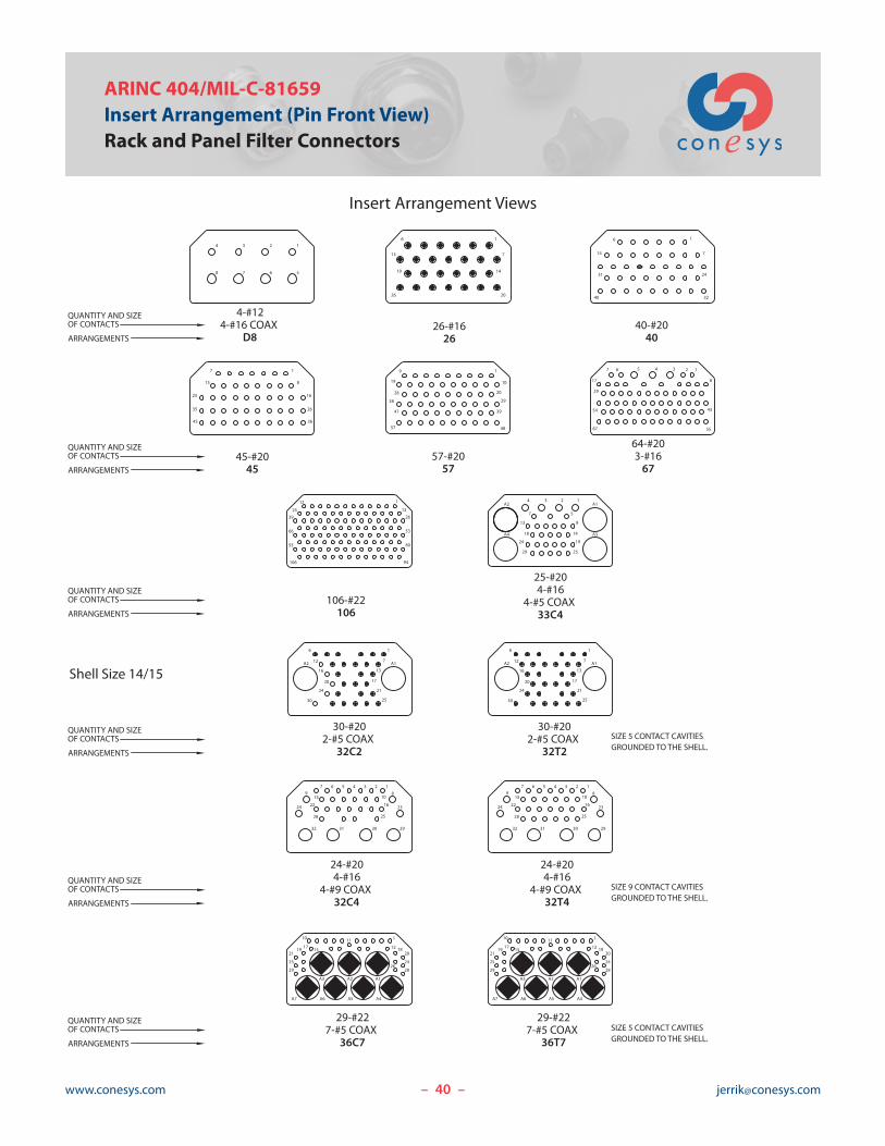
ARINC 404/MIL-C-81659Insert Arrangement (Pin Front View)Rack and Panel Filter Connectors
Insert Arrangement Views
QUANTITY AND SIZEOF CONTACTS
ARRANGEMENTS
64-#203-#1667
106-#22106
25-#204-#16
4-#5 COAX33C4
26-#1626
40-#2040
45-#2045
Shell Size 14/15
17
5567
43
8
29
1
54
234567
3925
12
2613
1 A2
14
25
5
19
8
1
5366
8093
94106
A4 A3
A1234
7
13
18
24
29
7
14
1
20
6
13
26
19
6
14
40
31 24
32
7
1
1
8
16
26
3645
35
25
7
15
57-#2057
30-#202-#5 COAX
32C2
1
10
20
4857
47
19
9
29
39
28
38
17
13
7
1
A2 A1
21
25
6
16
20
24
30
12
30
24
20
16
12A2
6
A1
25
21
17
13
7
1
30-#202-#5 COAX
32T2
23
29
24
24-#204-#16
4-#9 COAX32C4
24-#204-#16
4-#9 COAX32T4
19 8
234567
1015
1622
2528
303132
7 6 5 4 3 2 18
10
2316
29
25
3031
159
24 22
28
32
1
4-#124-#16 COAX
D8
234
5678
29-#227-#5 COAX
36C7
17 15 12
110 11
A7 A6 A5 A4
A1A2A3
20
24
28
19 18
29
25
21
26
29-#227-#5 COAX
36T7
29
25
211719
A3
A6A7
15
10
2628
24
201812
A1
A4
1
A2
A5
11
SIZE 5 CONTACT CAVITIESGROUNDED TO THE SHELL.
SIZE 9 CONTACT CAVITIESGROUNDED TO THE SHELL.
SIZE 5 CONTACT CAVITIESGROUNDED TO THE SHELL.
QUANTITY AND SIZEOF CONTACTS
ARRANGEMENTS
QUANTITY AND SIZEOF CONTACTS
ARRANGEMENTS
QUANTITY AND SIZEOF CONTACTS
ARRANGEMENTS
QUANTITY AND SIZEOF CONTACTS
ARRANGEMENTS
QUANTITY AND SIZEOF CONTACTS
ARRANGEMENTS

41www.conesys.com [email protected]– –
Page 38 Completed Part NumberPage 40 Insert ArrangementsPages 10–11 Electrical PerformancePage 9 Mechanical and Environmental PerformancePages 10–11 Filter Selection
ARINC 404/MIL-C-81659J4*R1 and J4*R2
Rack and Panel Filter Connectors
Size 1 Receptacle
Size 2 Receptacle
.720±.005
2.000
2.012
1.437
1.720±.005
4 MOUNTING HOLES[ .120 FOR #4-40 SCREWS
4 MOUNTING HOLES[ .120 FOR #4-40 SCREWS
.125
.060
OR CLINCH NUTS
.718±.005
2.000
3.075
2.783±.005
2.468
1.437
2 HOLES [ .120 FOR MOUNTINGREFERENCE ONLY
.060
.125
1.600 MAX.
OR CLINCH NUTS
R.189 TYP.
1.600 MAX

42www.conesys.com [email protected]– –
Page 38 Completed Part NumberPage 40 Insert ArrangementsPages 10–11 Electrical PerformancePage 9 Mechanical and Environmental PerformancePages 10–11 Filter Selection
ARINC 404/MIL-C-81659J4*R3Rack and Panel Filter Connectors
Size 3 Receptacle
4.315
.718 ±.005
R .189 TYP.
4.025
1.437
2.000
.125
.060
1.600 MAX
OR CLINCH NUTS
2 HOLES [ .120FOR MOUNTING
REFERENCE ONLY
4 MOUNTING HOLES [ .120FOR #4-40 SCREWS

43www.conesys.com [email protected]– –
Page 38 Completed Part NumberPage 40 Insert ArrangementsPages 10–11 Electrical PerformancePage 9 Mechanical and Environmental PerformancePages 10–11 Filter Selection
ARINC 404/MIL-C-81659J4*R4
Rack and Panel Filter Connectors
Size 4 Receptacle
3.8703.846
.930
1.648
2.783 3.0803.060
R .189 TYP.
6 MOUNTING HOLES [ .120FOR #4-40 SCREWS
.125
.060
1.600 MAX
OR CLINCH NUTS
4 HOLES [ .120FOR MOUNTING
REFERENCE ONLY
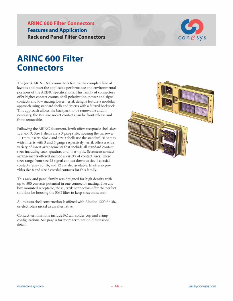
44www.conesys.com [email protected]– –
ARINC 600 Filter ConnectorsFeatures and ApplicationRack and Panel Filter Connectors
ARINC 600 FilterConnectors
The Jerrik ARINC 600 connectors feature the complete line oflayouts and meet the applicable performance and environmentalportions of the ARINC specifications. This family of connectorsoffer higher contact counts, shell polarization, power and signalcontacts and low mating forces. Jerrik designs feature a modularapproach using standard shells and inserts with a filtered backpack.This approach allows the backpack to be removable and, ifnecessary, the #22 size socket contacts can be front release andfront removable.
Following the ARINC document, Jerrik offers receptacle shell sizes1, 2 and 3. Size 1 shells are a 3 gang style, housing the narrower11.1mm inserts. Size 2 and size 3 shells use the standard 26.34mmwide inserts with 3 and 6 gangs respectively. Jerrik offers a widevariety of insert arrangements that include all standard contactsizes including coax, quadrax and fiber optic. Seventeen contactarrangements offered include a variety of contact sizes. Thesesizes range from size 22 signal contact down to size 1 coaxialcontacts. Sizes 20, 16, and 12 are also available. Jerrik also pro-vides size 8 and size 5 coaxial contacts for this family.
This rack and panel family was designed for high density withup to 800 contacts potential in one connector mating. Like anybox mounted receptacle, these Jerrik connectors offer the perfectsolution for housing the EMI filter to keep stray noise out.
Aluminum shell construction is offered with Alodine 1200 finish,or electroless nickel as an alternative.
Contact terminations include PC tail, solder cup and crimpconfigurations. See page 4 for more termination dimensionaldetail.

45www.conesys.com [email protected]– –
ARINC600Insert Arrangement (Pin Front View)
Rack and Panel Filter Connectors
Insert Arrangement Views
106-#22106
4-#20, 3-#16, 4-#122-#5 COAX
13C2
40-#2240
60-#2260
100-#22100
80-#22, 4-#20, 1-#1685
150-#22150
2-#16, 1-#12,2-#5 COAX
5C260-#2260
24-#20, 10-#1634
6-#8 TWINAX ORCOAX6T6
1
2
4
3
5
1 A B C D
2
3
4
5
6
7
8
9
10
CBA1
10
5
15
10
15
5
1
A B C
1
7
6
5
4
3
2
A B C D
1T
2T
A B C D E F G H J
JHGFEDCBA
1
5
10
5
1
10
JHGFEDCBA
1
5
8
1
5
8
1 2 4 53
1 2 3 4 5 6
7 8 9 10 11 12
13 14 15 16 17 18
19 20 21 22 23 24
25
30
26
31
27
32
28
33
29
34
JHGFEDCBA1
2
3
4
5
51
56
52 53 54 55
57 58 59
1234
6
8 7
5
91011
1213
1T
2T 3T
4T
6T5T
JHGFEDCBA1
5
JHGFEDCBA
10
15
1
5
10
15
2-#8 TWINAX, 118-#22120T2
10
5
1 DCBA JHGFE
1T 2T
4
3
2
9
8
7
6
11
12
13
14
15
60-#2060
1 2 3 4 5 6
121110987
13 14 15 16 17 18
212019 242322
272625 302928
333231 363534
393837 424140
454443 484746
515049 545352
575655 605958
70-#22, 1-#1 COAX71C1
5 5
1DCBA
1JHGFE
7 7
71
2
110-#22, 6-#20, 5-#16121
114
120116 117 118 119
10
111 112
5
113
CA1
B D E F
121
5
10
115
1HG J
4-#1 COAXC4
2-#1 COAXC2
1
4
3
C1
C2
Shell Size 14/15
QUANTITY AND SIZEOF CONTACTS
ARRANGEMENTS
QUANTITY AND SIZEOF CONTACTS
ARRANGEMENTS
QUANTITY AND SIZEOF CONTACTS
ARRANGEMENTS
QUANTITY AND SIZEOF CONTACTS
ARRANGEMENTS
QUANTITY AND SIZEOF CONTACTS
ARRANGEMENTS

46www.conesys.com [email protected]– –
Page 38 Completed Part NumberPage 45 Insert ArrangementsPages 10–11 Electrical PerformancePage 9 Mechanical and Environmental PerformancePages 10–11 Filter Selection
ARINC 600J6*R1Rack and Panel Filter Connectors
Size 1 Receptacle1.010.990
.655
.645
7.4557.425
6.3556.345
.360
1.580
.065
.055
.130
.120
5.6255.585
6.0796.019
OR CLINCH NUTS
4 MOUNTING HOLES[ .148±.003 FOR #6-32 SCREWS

47www.conesys.com [email protected]– –
Page 38 Completed Part NumberPage 45 Insert ArrangementsPages 10–11 Electrical PerformancePage 9 Mechanical and Environmental PerformancePages 10–11 Filter Selection
ARINC 600J6*R2
Rack and Panel Filter Connectors
Size 2 Receptacle1.8101.790
1.4311.421
.655
.645
6.9756.945
6.3556.345
2.1352.125
1.580
.130
.120
.065
.060
5.8305.770
5.6255.585
OR CLINCH NUTS
4 HOLES [ .148±.003 FORMOUNTING REFERENCE ONLY 6 MOUNTING HOLES [ .148±.003
FOR #6-32 SCREWS

48www.conesys.com [email protected]– –
Page 38 Completed Part NumberPage 45 Insert ArrangementsPages 10–11 Electrical PerformancePage 9 Mechanical and Environmental PerformancePages 10–11 Filter Selection
ARINC 600J6*R3Rack and Panel Filter Connectors
Size 3 Receptacle3.2753.245
2.8912.881
1.9551.945
.655
.645
6.9756.945
6.3556.345
2.1352.125
1.580
.130
.120
.065
.060
5.8305.770
5.6255.585
OR CLINCH NUTS
4 HOLES [ .148±.003 FORMOUNTING REFERENCE ONLY 6 MOUNTING HOLES [ .148±.003
FOR #6-32 SCREWS
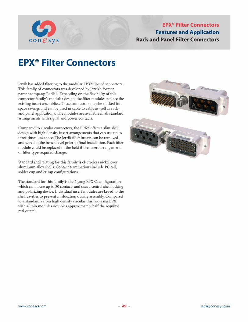
49www.conesys.com [email protected]– –
EPX® Filter ConnectorsFeatures and Application
Rack and Panel Filter Connectors
EPX® Filter Connectors
Jerrik has added filtering to the modular EPX® line of connectors.This family of connectors was developed by Jerrik’s formerparent company, Radiall. Expanding on the flexibility of thisconnector family’s modular design, the filter modules replace theexisting insert assemblies. These connectors may be stacked forspace savings and can be used in cable to cable as well as rackand panel applications. The modules are available in all standardarrangements with signal and power contacts.
Compared to circular connectors, the EPX® offers a slim shelldesign with high density insert arrangements that can use up tothree times less space. The Jerrik filter inserts can be removedand wired at the bench level prior to final installation. Each filtermodule could be replaced in the field if the insert arrangementor filter type required change.
Standard shell plating for this family is electroless nickel overaluminum alloy shells. Contact terminations include PC tail,solder cup and crimp configurations.
The standard for this family is the 2 gang EPXB2 configurationwhich can house up to 80 contacts and uses a central shell lockingand polarizing device. Individual insert modules are keyed to theshell cavities to prevent mislocation during assembly. Comparedto a standard 79 pin high density circular this two gang EPXwith 40 pin modules occupies approximately half the requiredreal estate!
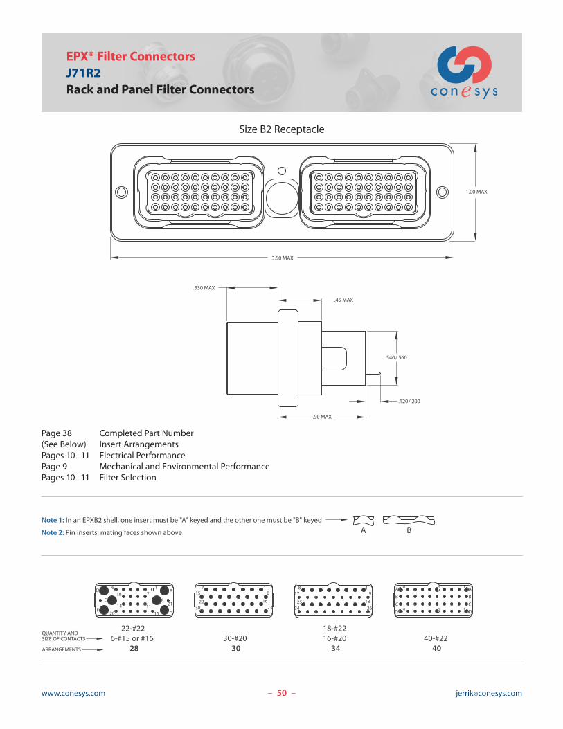
Page 38 Completed Part Number(See Below) Insert ArrangementsPages 10–11 Electrical PerformancePage 9 Mechanical and Environmental PerformancePages 10–11 Filter Selection
50www.conesys.com [email protected]
Size B2 Receptacle
– –
EPX® Filter ConnectorsJ71R2Rack and Panel Filter Connectors
Note 1: In an EPXB2 shell, one insert must be "A" keyed and the other one must be "B" keyed
D
F
Note 2: Pin inserts: mating faces shown above
QUANTITY ANDSIZE OF CONTACTS
ARRANGEMENTS
22-#226-#15 or #16
28
14
10E
20
6
B7
1115
1
C21
A
3022
157
30-#2030
1623
18 17
3425
8
18-#2216-#20
34
9
1826
1
A
DC
B
A
10
10
40-#2240
5
5
B
D1C
A1
B
3.50 MAX
.45 MAX
.90 MAX
.530 MAX
.540/.560
.120/.200
1.00 MAX

Jerrik Inc., A Conesys CompanyJerrik Inc. – CAGE CODE: 4KVE4
Catalog JK101 (9/2008)Specifications are subject to change without notice. Consult Jerrik Inc. for latest design specifications. All statements, information and data provided hereinare believed to be accurate and reliable but are presented without guarantee, warranty or responsibility of any kind, expressed or implied. The user shouldnot assume that all safety measures are indicated or that other measures may not be required.

Aero-Electric Connector548 Amapola Ave.
Torrance, California 90501Tel: 310.618.3737Fax: 310.618.3738
EMP Connectors1631 E. St. Andrew Place
Santa Ana, California 92705Tel: 714.665.2085Fax: [email protected]
J-Tech1631 E. St. Andrew Place
Santa Ana, California 92705Tel: 714.665.2080Fax: [email protected]
Jerrik102 West Julie DriveTempe, Arizona 85283Tel: 480.730.5700Fax: [email protected]
Conesys Europe20, avenue Jean-Monnet31770 Colomiers. FranceTel: 33.5.61.15.34.20Fax: 33.5.61.15.48.11
Aero Industrial Products10138 Radiance Drive
Ira Township, Michigan 48023Tel: 586.716.1257Fax: [email protected]
www.conesys.com


