24
LOCATING METHODS AND DEGREE OF FREEDOM
| Date post: | 10-Aug-2015 |
| Category: |
Documents |
| Upload: | jes-thomas |
| View: | 73 times |
| Download: | 2 times |
LOCATING METHODS AND DEGREE OF
FREEDOM
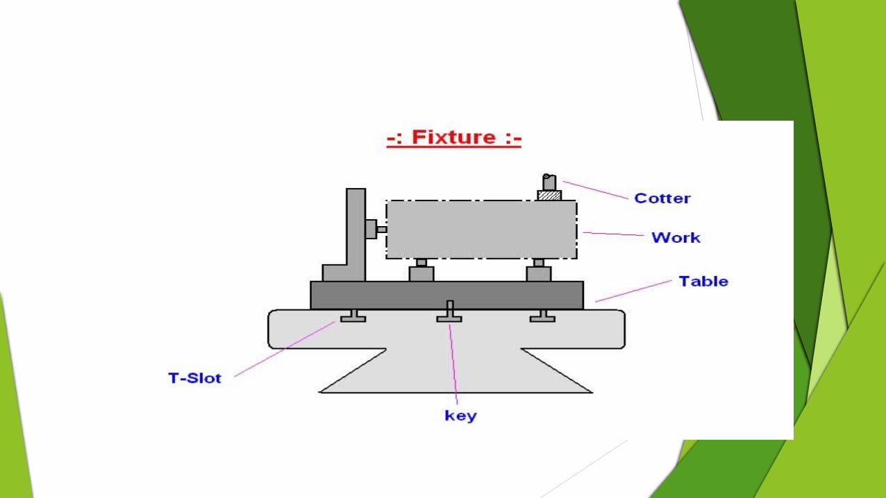
FIXTURES AND JIGS
FIXTURES
Fixtures used in machine shop, are strong and rigid mechanical devices which enables easy, quick and consistently accurate locating, supporting and clamping workpieces against cutting tools and result faster and accurate machining with consistent quality, functional ability and interchangeability.
JIGS
Jig is a type of custom-made tool used to control the location and/or motion of another tool. A jig's primary purpose is to provide repeatability, accuracy, and interchangeability in the manufacturing of products.
eg:drill jig , pcb(printed circuit board) jig
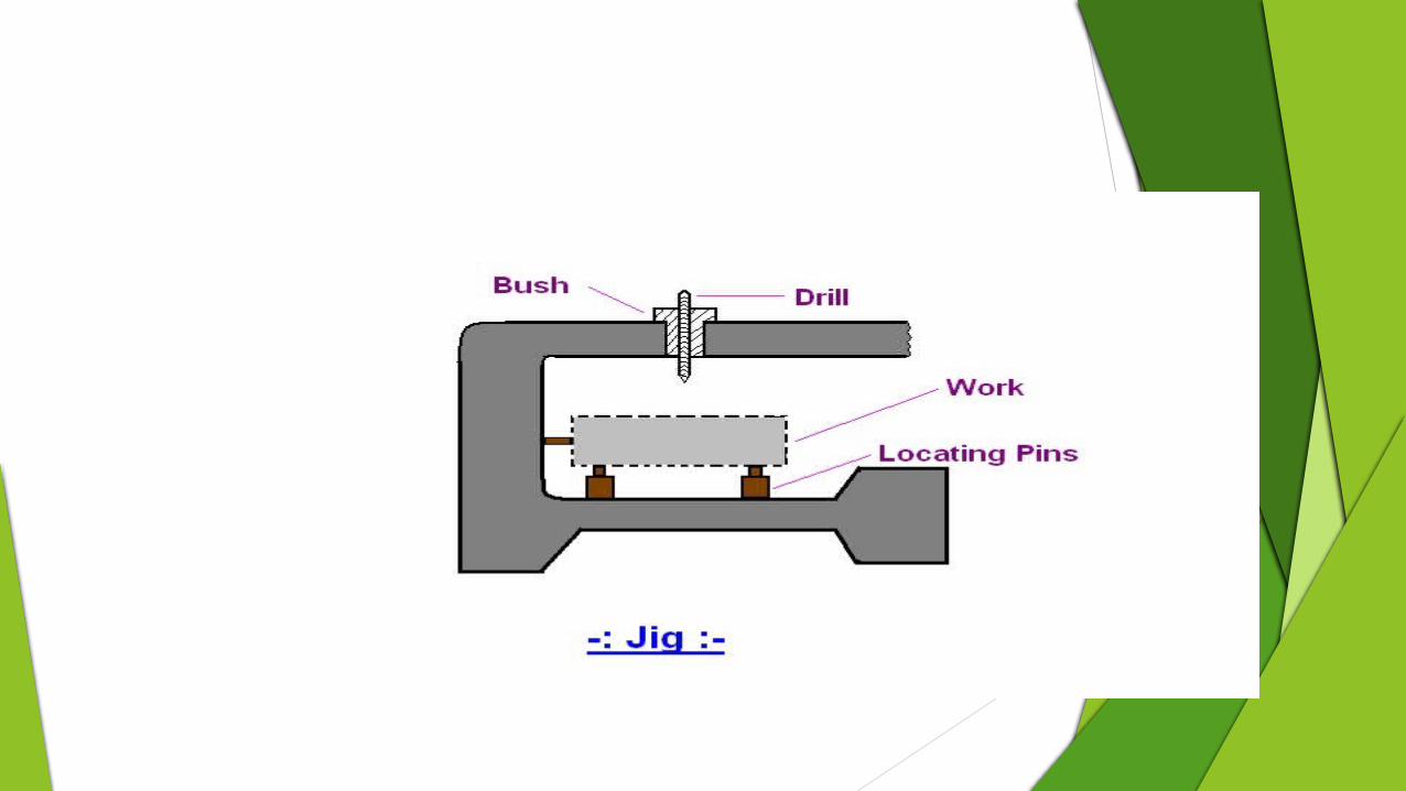
A jig is often confused with a fixture; a fixture holds the work in a fixed location. A device that does both functions (holding the work and guiding a tool) is called a jig.
A jig is a type of tool that is used to control the location and/or motion of another tool.
A fixture, on the other hand, is a work-holding or support device, used to hold the work in place.
PRINCIPLES OR RULES OF LOCATING IN JIGS AND FIXTURES
For accurate machining, the workpiece is to be placed and held in correct position and orientation in the fixture (or jig) which is again appropriately located and fixed with respect to the cutting tool and the machine tool.
The workpiece is free to revolve around or move parallel to any axis in either direction
Any solid body may have maximum twelve degrees of
freedom as indicated in Figure.
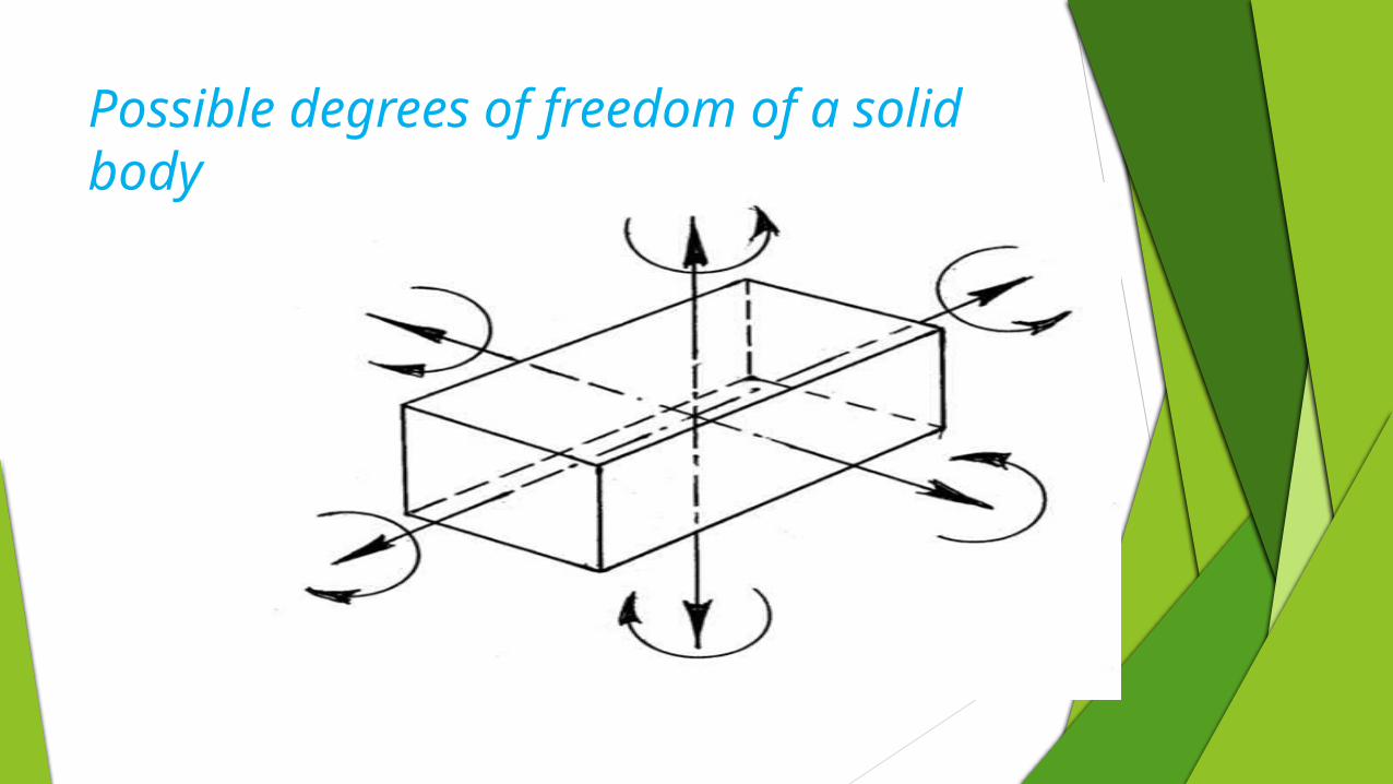
Possible degrees of freedom of a solid body
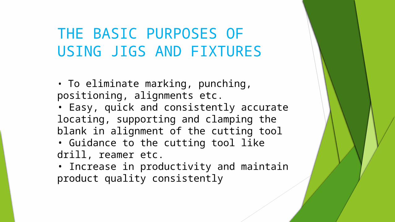
THE BASIC PURPOSES OF USING JIGS AND FIXTURES
• To eliminate marking, punching, positioning, alignments etc. • Easy, quick and consistently accurate locating, supporting and clamping the blank in alignment of the cutting tool • Guidance to the cutting tool like drill, reamer etc. • Increase in productivity and maintain product quality consistently
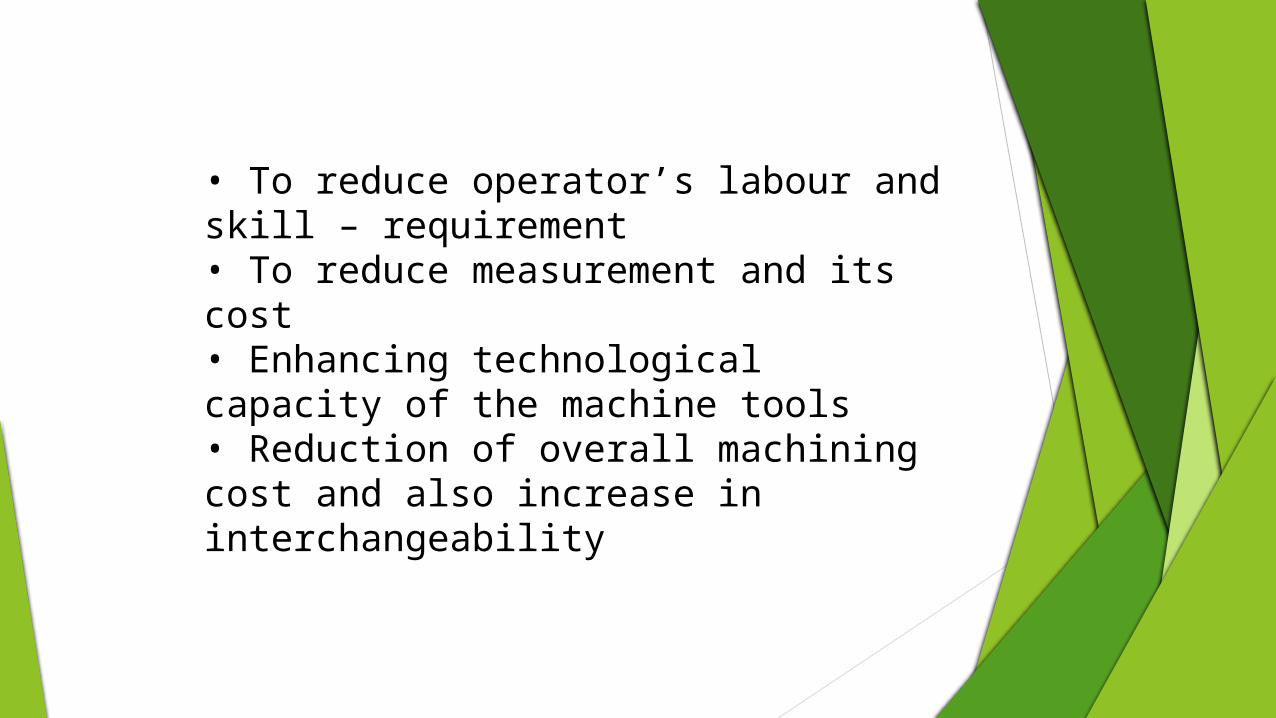
• To reduce operator’s labour and skill – requirement • To reduce measurement and its cost • Enhancing technological capacity of the machine tools • Reduction of overall machining cost and also increase in interchangeability
SOME BASIC PRINCIPLES
Some basic principles or rules are usually followed while
designing for locating, supporting and clamping of blank in
fixtures.
One or more surfaces (preferably machined) and / or
drilled / bored hole(s) are to be taken for reference
The reference surfaces should be significant and
important feature(s) based on which most of the
dimensions are laid down
Locating should be easy, quick and accurate
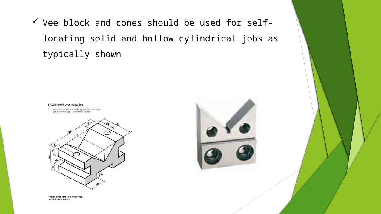
Vee block and cones should be used for self-locating
solid and hollow cylindrical jobs as typically shown
In case of locating by pin, the pins and their
mounting and contact points should be strong,
rigid and hard
The locating pins should be as far apart as feasible
A minimum of three point must be used to locate a
horizontal flat surface
Sight location is applicable to first – operation
location of blank with irregular surfaces produced
by casting, forging etc.
LOCATING
Placing a work piece in a machine for machining is called locating
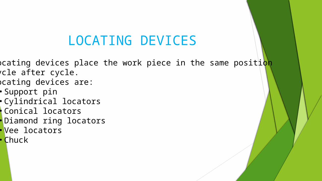
LOCATING DEVICES
Locating devices place the work piece in the same positionCycle after cycle.Locating devices are:
• Support pin• Cylindrical locators• Conical locators• Diamond ring locators• Vee locators• Chuck
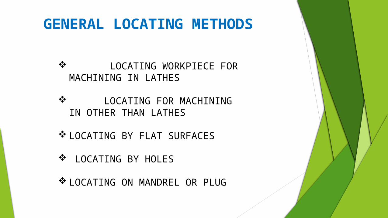
LOCATING WORKPIECE FOR MACHINING IN LATHES
LOCATING FOR MACHINING IN OTHER THAN LATHES
LOCATING BY FLAT SURFACES
LOCATING BY HOLES
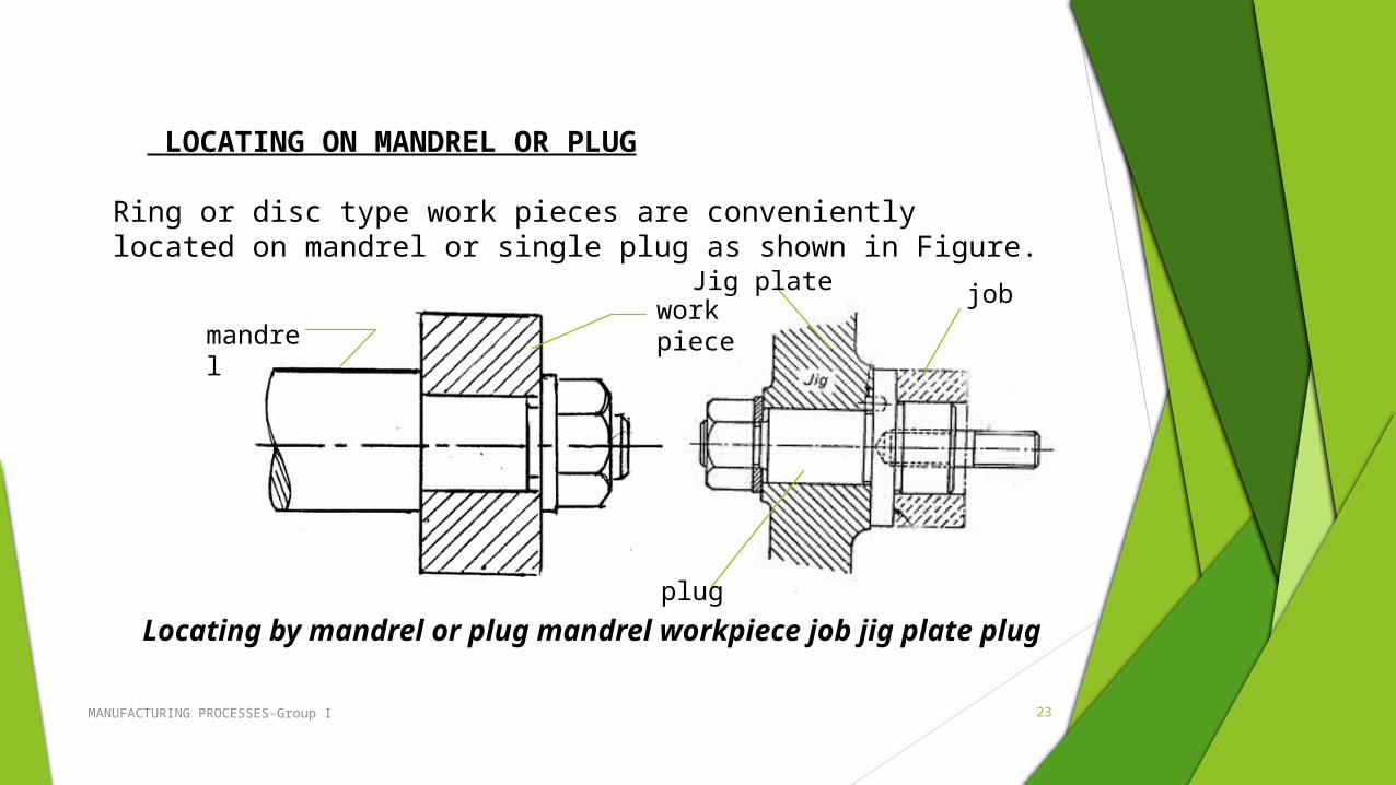
LOCATING ON MANDREL OR PLUG
GENERAL LOCATING METHODS
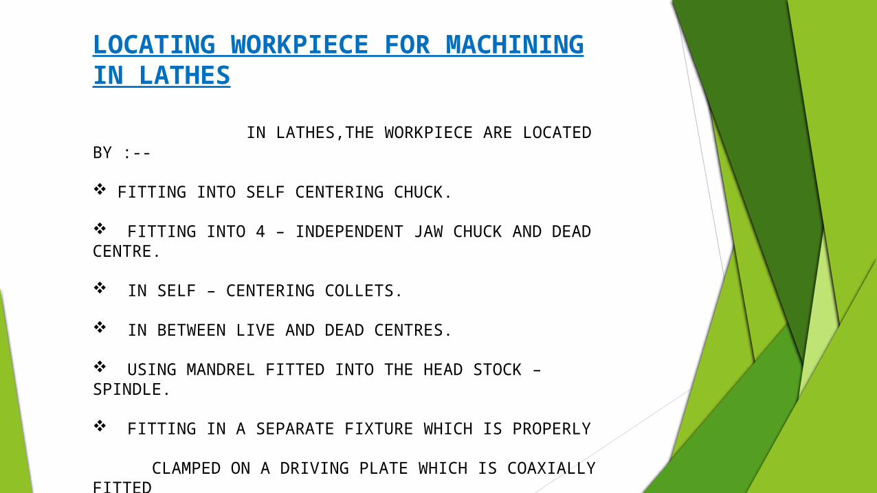
LOCATING WORKPIECE FOR MACHINING IN LATHES
IN LATHES,THE WORKPIECE ARE LOCATED BY :--
FITTING INTO SELF CENTERING CHUCK.
FITTING INTO 4 – INDEPENDENT JAW CHUCK AND DEAD CENTRE.
IN SELF – CENTERING COLLETS.
IN BETWEEN LIVE AND DEAD CENTRES.
USING MANDREL FITTED INTO THE HEAD STOCK –SPINDLE.
FITTING IN A SEPARATE FIXTURE WHICH IS PROPERLY CLAMPED ON A DRIVING PLATE WHICH IS COAXIALLY FITTED INTO THE LATHE SPINDLE.
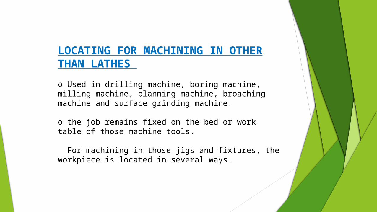
LOCATING FOR MACHINING IN OTHER THAN LATHES
o Used in drilling machine, boring machine, milling machine, planning machine, broaching machine and surface grinding machine.
o the job remains fixed on the bed or work table of those machine tools.
For machining in those jigs and fixtures, the workpiece is located in several ways.
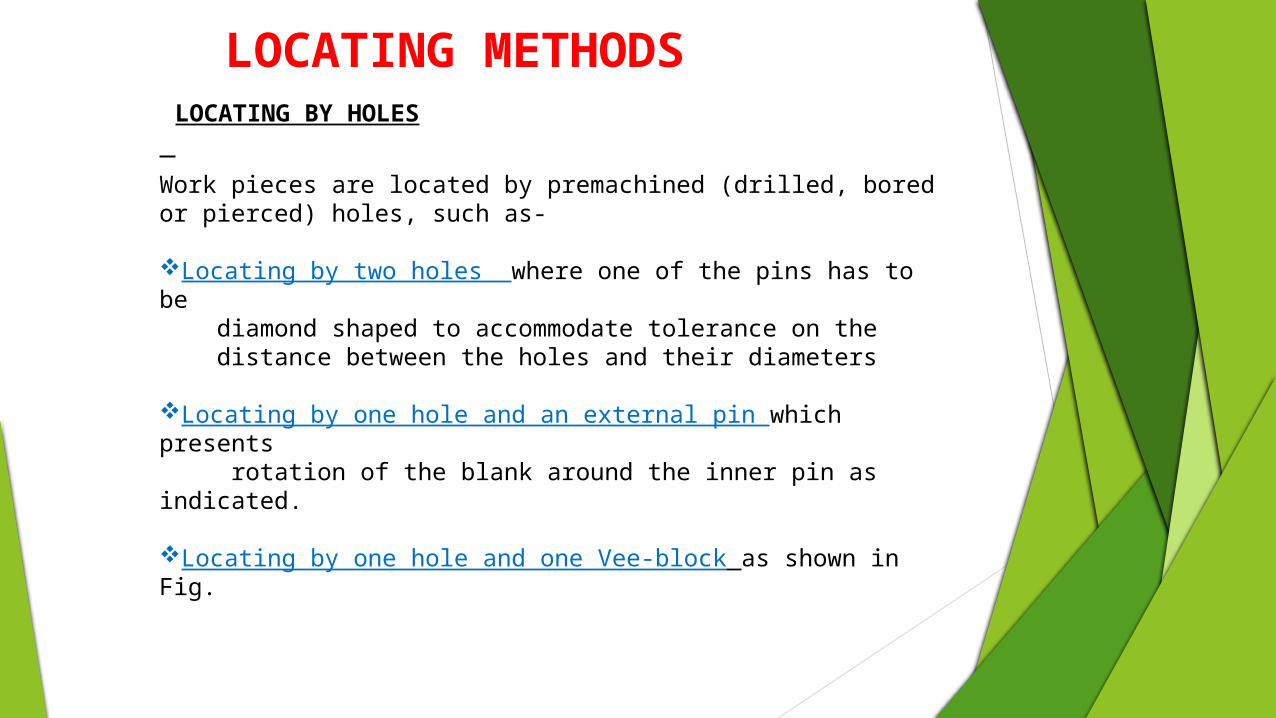
Work pieces are located by premachined (drilled, bored or pierced) holes, such as-
Locating by two holes where one of the pins has to be diamond shaped to accommodate tolerance on the distance between the holes and their diameters
Locating by one hole and an external pin which presents rotation of the blank around the inner pin as indicated.
Locating by one hole and one Vee-block as shown in Fig.
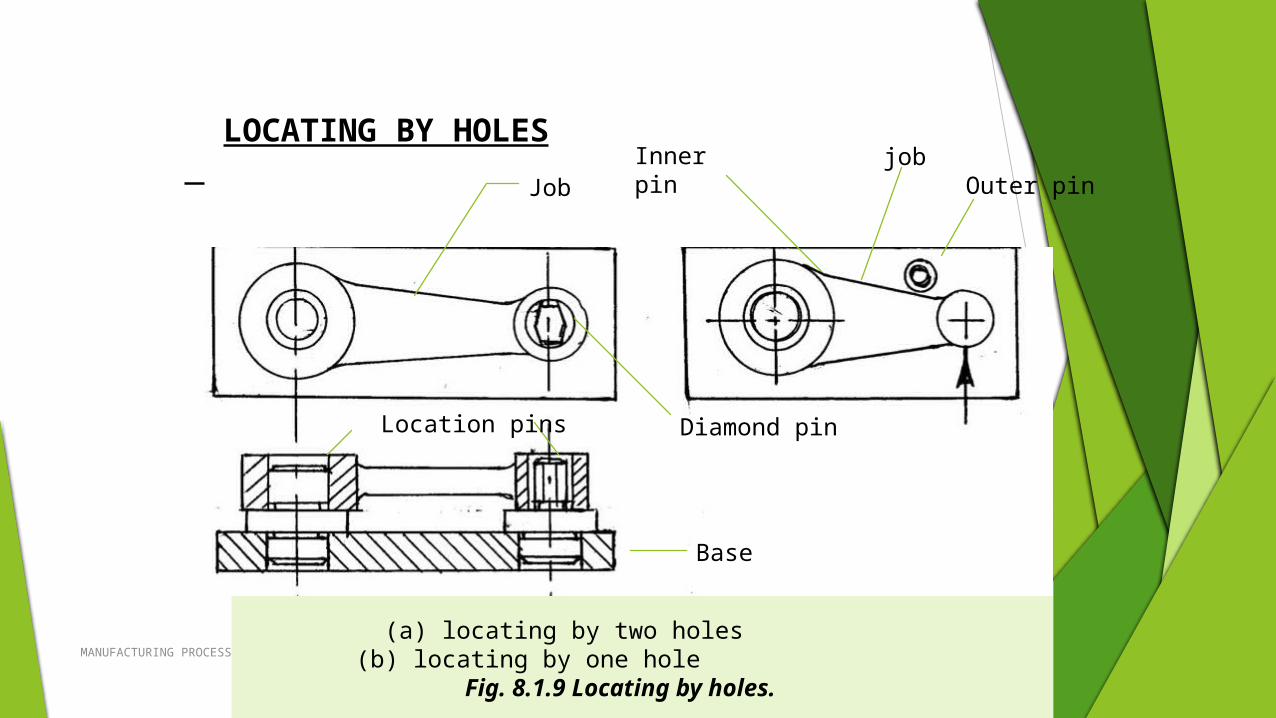
LOCATING BY HOLES
LOCATING METHODS
MANUFACTURING PROCESSES-Group I 22
(a) locating by two holes (b) locating by one hole Fig. 8.1.9 Locating by holes.
LOCATING BY HOLES
Job
Diamond pin
Inner pin jobOuter pin
Location pins
Base
MANUFACTURING PROCESSES-Group I 23
LOCATING ON MANDREL OR PLUG
Ring or disc type work pieces are conveniently located on mandrel or single plug as shown in Figure.
Locating by mandrel or plug mandrel workpiece job jig plate plug
mandrel
work pieceJig plate job
plug

THANK YOU!


