JITeR: Just-In-Time Application-Layer Routing 1 Alysson Bessani, 1 Nuno F. Neves, 2 Paulo Ver´ ıssimo, 3 Wagner Dantas, 4 Alexandre Fonseca, 4 Rui Silva, 4 Pedro Luz, 4 Miguel Correia 1 LaSIGE/FCUL, Portugal 2 Uni.Lu, Luxembourg 3 UFSC, Brazil 4 INESC-ID/IST, Portugal Abstract The paper addresses the problem of providing message latency and reliability assurances for control traffic in wide-area IP networks. This is an important problem for cloud services and other geo-distributed information infrastruc- tures that entail inter-datacenter real-time communication. We present the design and validation of JITeR (Just-In-Time Routing ), an algorithm that timely routes messages at application-layer using overlay networking and multihoming, leveraging the natural redundancy of wide-area IP networks. We implemented a prototype of JITeR that we evaluated experimentally by placing nodes in several regions of Amazon EC2. We also present a scenario- based (geo-distributed utility network) evaluation comparing JITeR with alternative overlay/multihoming routing algorithms that shows that it pro- vides better timeliness and reliability guarantees. Preprint submitted to Computer Networks February 25, 2016
1LaSIGE/FCUL, Portugal 2Uni.Lu, Luxembourg 3UFSC, Brazil 4INESC-ID/IST,Portugal
Abstract
The paper addresses the problem of providing message latency and reliabilityassurances for control traffic in wide-area IP networks. This is an importantproblem for cloud services and other geo-distributed information infrastruc-tures that entail inter-datacenter real-time communication. We present thedesign and validation of JITeR (Just-In-Time Routing), an algorithm thattimely routes messages at application-layer using overlay networking andmultihoming, leveraging the natural redundancy of wide-area IP networks.We implemented a prototype of JITeR that we evaluated experimentally byplacing nodes in several regions of Amazon EC2. We also present a scenario-based (geo-distributed utility network) evaluation comparing JITeR withalternative overlay/multihoming routing algorithms that shows that it pro-vides better timeliness and reliability guarantees.
Preprint submitted to Computer Networks February 25, 2016
1LaSIGE/FCUL, Portugal 2Uni.Lu, Luxembourg 3UFSC, Brazil 4INESC-ID/IST,Portugal
1. Introduction
An increasing number of applications over wide-area IP networks exhibittimeliness requirements. Many of them can be served by protocols thatprovide those guarantees most of the time, for example by guaranteeing agiven average throughput and accepting occasional violations of deadlines(e.g., video streaming). However, other applications exhibit more stringentrequirements, i.e., the need that some of their messages meet individual dead-lines in the presence of faults like congestion and omissions. Whilst solutionsexist to the problem within over-provisioned datacenter networks, we knowof no solution for generic wide-area IP networks.
This paper addresses the problem of providing latency and reliabilityassurances for control traffic – not for all traffic – in wide-area IP networks.Two examples show the relevance of the work for what we designate by geo-distributed information infrastructures (GDII).
First, cloud services with soft real-time requirements often span multipledatacenters in different geographical locations, implying deadline propaga-tion amongst them, hampered by the wide-area IP network interconnects [58].An example are cloud services that need to exchange control traffic such asGoogle’s Megastore coordination service access [8] and Amazon’s Dynamofailure detection protocol [17].
The second example is the context of critical information infrastructures,such as power generation, transport and distribution. Such cyber-physicalsystems are spread over large geographical areas and controlled remotelyfrom command and control centers using SCADA/PCS1 systems, over com-
1Supervisory Control and Data Acquisition (SCADA) and Process Control Systems
Preprint submitted to Computer Networks February 25, 2016
munication networks usually based on wide-area IP networks [20, 31, 37, 10].Despite the use of IP, the timeliness of critical remote commands is essentialto maintain the integrity of the infrastructure (e.g., to avoid power out-ages). Several examples of such applications and commands were describedin project CRUTIAL [23].
We present the design and validation of a novel algorithm for Just-In-Time Routing, JITeR (pronounced “jitter”), which routes deadline con-strained messages –control messages– at application layer, using an overlaynetwork created on top of a multihomed communication infrastructure, lever-aging the natural communication redundancy that exists in geo-distributedinformation infrastructures [37]. JITeR uses a set of nodes located in differ-ent sites of the GDII to route messages among them, instead of following theroutes imposed by the network-level routing. For instance, if the network-level routing makes a message sent by node ra to node rb pass through theautonomous system AS1, ra may send the message to rc and this node sendit to rb, letting the message pass alternatively through AS2 and AS3.
Our scheme is based on two important assumptions. The first is thatamongst a collection of alternative overlay routes between two sites, therewill be a subset which will be fast enough to perform reliable and timelycommunication in the presence of faults. The second is that it is used tosend only control traffic and that that traffic consumes negligible resources(e.g., bandwidth) in comparison to the rest of the traffic.
The key objective of our work is to devise a practical and non-intrusivesolution to achieve timely and reliable communication with high probabilityin current GDIIs, taking three requirements into consideration: (1.) Com-patibility with current GDIIs: JITeR should allow seamless integration withcurrent GDIIs, without requiring major changes to the operation and orga-nization of existing networks; (2.) No wide-area IP network changes: thesolution should not require any special support from the underlying network(e.g., resource reservation). Timeliness should be obtained on top of best-effort communication channels such as those provided by IP-based networks,and therefore, JITeR cannot ensure strict hard real-time properties (e.g.,like in small-scale real-time networks); and (3) Cost consciousness: JITeRshould use redundancy parsimoniously, avoiding expensive solutions like traf-fic flooding.
(PCS).
3
Unlike previous works on overlay networks, which aim to improve relia-bility by detecting and deviating communication from faulty and congestedpaths, JITeR aims to provide soft real-time communication by securing in-dividual message delivery deadlines with high probability. To achieve thisgoal, JITeR uses temporal and spatial redundancy judiciously. In a nut-shell, each message is sent through several overlay channels, possibly fromdifferent service providers: one base channel plus a few backup channels. Inthe presence of delays or omissions, the message may be retransmitted. Anovel channel scheduling policy in the JITeR algorithm, which we call just-in-time, selects the base and backup channels not to be the fastest, but theones which match each message’s deadline needs (some faster, some slower).The reader may wonder that it is impossible to guarantee real-time behav-ior on best-effort IP networks. As a matter of fact, not even hard real-timesystems have 100% coverage: they have to achieve sufficient coverage [53].
We implemented JITeR and evaluated it experimentally by placing nodesin several regions of the Amazon AWS cloud offering (in the EC2 service).Moreover, we evaluated the strategy by simulation of scenarios over a realisticmodel of a wide-area utility network (the Italian electric power infrastructure)with both accidental and malicious faults (DDoS attacks). Its effectivenessand costs were compared with several other overlay/multihoming routingalgorithms in the literature. The evaluation showed that JITeR providesbetter timeliness and reliability guarantees than the other schemes, very closeto those of a flooding strategy but sending much fewer messages.
The paper provides the following contributions:
1. JITeR, the first (to the best of our knowledge) wide-area IP over-lay network algorithm and architecture with the objective of providingmessage latency and reliability guarantees;
2. A comparative analysis of several overlay networks proposed in theliterature, showing that JITeR provides better timeliness;
3. The description and modelling of a representative critical informationinfrastructure, the Italian power system utility network, which we be-lieve to be of use as a benchmark for future studies.
4. An evaluation of JITeR and other techniques in providing timely com-munication between Amazon EC2 regions. This analysis also shows thecommunication latency and path diversity between the EC2 availabilityzones.
4
2. Related Work
There is a vast bibliography on the topic of the paper, so this sectionis necessarily a summary. It presents work along the following axes: theproperties we want to provide (QoS, timeliness); existing challenges (net-work failures), the techniques we use (overlay networks, multihoming); thescenarios we consider (clouds, critical information infrastructures).
QoS in multimedia networks. We assume that the network provides only abest-effort service, with no latency and bandwidth guarantees. It is possibleto have these guarantees, e.g., by using DiffServ [38] or ATM [16]. However,these services are not provided by the generality of Internet service providers(ISPs), especially in a geo-distributed context, which would constrain theapplicability of our solution. It is also possible to use leased lines, whichare rather expensive. On the other hand, many ISPs provide phone and TVover IP, which have timeliness requirements. These providers usually employfast convergence mechanisms for sub-second recovery from link and routerfailures: bidirectional forwarding detection [33], stateful switchover [12], andfast hello packets [11]. Nevertheless, deadlines are frequently missed, causingimage freezes of several seconds. We propose a solution that does not requiresuch guarantees from the network, only plain Internet-like IP network service.
Peer-to-peer networks have been proposed as a solution to stream multi-media over best-effort networks such as the Internet. CoopNet is one of thefirst of this line of research [39]. It focus on live streaming and leverages thenotion of multiple description coding, i.e., of encoding audio and video intoseparate streams. Zigzag provides scalable single-source media streaming us-ing an application-layer multicast tree [51]. Promise is a peer-to-peer mediastreaming system that supports multiple senders and allows one recipient toreceive media from several senders [27]. These systems aim to provide QoSguarantees, but not specifically the delivery of messages before a certain, pos-sibly short, deadline. Moreover these systems tolerate some level of packetloss, whereas we are interested in delivering all messages. On the other hand,these systems handle much more traffic, as they are targeted at continuousmedia (audio, video).
Timeliness in networks. When the web started to be adopted for commercialpurposes, it became clear that there are limits on the time users are willingto accept for replies to arrive, i.e., that there are timeliness (maximum la-tency) requirements for web communication. Content distribution networks
5
(CDNs) like Akamai [19] appeared as a solution to this problem [7, 40]. Theapproach consists essentially in placing content geographically near its con-sumers, reducing the latency. This solution is unfeasible for the applicationswe envision as they do not have content to distribute, but control messagesthat have to be sent over a distance that cannot be reduced. There arecommon issues though, e.g., ensuring path diversity [7].
Recently there has been some work on the problem of ensuring time-liness in datacenter networks (e.g., [52, 57]). The fundamental differenceof these works in relation to ours is that they require modifications of thenetwork devices. Consequently, these solutions can not be easily adaptedto public/legacy networks, like the Internet and other WANs. However,they increase the significance of our work, since they motivate the needfor solving the deadline propagation problem in the geo-distributed inter-datacenter communication, for applications that span multiple datacenters,without modifying the network.
Network failures in IP backbones. Network backbone failures may adverselyaffect IP routing and delay or disrupt information infrastructure communi-cation. Studies on the impact of failures in IP backbones have shown thatthey occur daily, being often the result of problems either at or under theIP level [35]. Some of these problems can lead to network instability pe-riods and disrupt applications [30]. Other failures come from interferenceof misconfigured or obsolete routing protocols running in customer networksconnected to the ISP backbone [55]. Even stable core routing infrastructures,BGP-based, are prone to failures [46, 48]. Malicious faults can also happenas a result of acts of hacktivism, cyber-crime or cyber-terrorism [56], such asdistributed denial-of-service (DDoS) attacks, in which the attacker(s) use alarge number of computers (bots or zombies) to generate traffic and causecongestion [29, 36]. Depending on the capabilities of the attacker, the rate ofmessages delayed and lost can be alarmingly high. Research on this matteris vast and many ways of countering those attacks have appeared [44], but afinal solution is still to be found.
Overlay routing. Nodes of an overlay network relay messages through thevirtual paths among them, according to application-level criteria. This fitsquite well with applications with specific requirements, hard to satisfy by nor-mal wide-area networks. Therefore, over the years application-aware overlayrouting solutions have been proposed, with various virtual channel selection
6
schemes [2, 4, 6, 49, 50]. However, to the best of our knowledge none ofthese works aims to provide latency guarantees, which is the objective of ourwork. The most common objective of overlay routing algorithms is to de-viate traffic from channels that are faulty or congested. For instance, RONmonitors the network to decide to route messages directly or through anoverlay channel [4]. The works nearest to ours have the objective of improv-ing end-to-end communication latency, not of attaining individual messagedelivery deadlines [2, 49]. Spines, uses a dense overlay network with severaloverlay nodes per-channel, recovering missing packets in a per-hop basis [2].This recovery is attempted only once, since Spines targets video transmission,in which missing packets are undesirable, but acceptable to a certain level.Mesh-routing uses XML routers and the Diversity Control Protocol for mul-ticasting data [49]. Although timeliness appears to be a requisite, it is notclear whether or how it would be achieved in stringent scenarios with, for ex-ample, persistent packet losses caused by long-term congestions [6]. OverQoSexplores the controlled loss virtual link abstraction to provide statistical lossand bandwidth guarantees [50]. Han et al. introduced the idea of topology-aware overlay routing to improve the diversity of paths when detouring trafficto escape congestion or failures [26]. However, the topology may change dueto changes at network (IP) layer routing, so we do not create an overlay net-work based on the topology, but instead select overlay channels dynamicallytaking diversity into account.
We defer to Section 5.1 and Table 1 a more detailed comparison of RON,Mesh-routing and other overlay routing strategies with JITeR.
Multihoming. Multihoming allows hosts to access a WAN through two ormore redundant links, to resist network failures like those exemplified aboveand improve properties such as availability and performance [9]. Informationinfrastructure stakeholders frequently deploy IP connections contracted withmore than one ISP [1]. The work closest to ours in the sense of exploitingoverlays and multihoming is MONET [5], but its objective is to mask faultsand improve the availability perceived by web clients. On the contrary toJITeR, MONET does not take latency explicitly into consideration, as itdoes not aim to meet message deadlines.
The initial ideas of JITeR appeared in a workshop position paper someyears ago [15]. That paper also explored overlay networks and multihoming.The present paper thoroughly improves on that earlier version in severalways: the algorithm was improved, is now formalized and its properties dis-
7
cussed; we compare it analytically with other representative routing strate-gies; we implemented it and have experimental results; the simulations isway more complete and realistic (e.g., underlying network routing effects areaccounted for, more strategies are compared) and provide more results.
Cloud communication and SDNs. The popularity of software defined net-works (SDNs) promises to increase the possibility to control the networkfabric by applications. In particular, recently Google showed how it managesits dedicated inter-datacenter backbone (a WAN) using SDN technology toachieve impressive levels of bandwidth utilization without sacrificing appli-cation SLAs (including latency) [32]. Their design is based on a centralizedtraffic engineering algorithm that controls the network. Although not ex-plicitly designed for timeliness, this solution can solve or at least alleviatethe need for an application level solution like JITeR. However, we do notenvision solutions like that being used for systems spanning multiple admin-istrative domains (without centralized control) or for critical information in-frastructures (GDIIs) that usually do not own the communication backbone(e.g., power grid operators).
Critical information infrastructure communication. Ratatoskr [54] exploitsseveral channels and retransmissions to provide communication timelinessin critical infrastructures, but on the contrary of JITeR it does not try toenforce deadlines explicitly and it is based on a publish-subscribe middle-ware, GridStat [24]. Esposito et al. present a broadcast protocol for publish-subscribe systems [22]. This protocol aims to support reliable communicationamong the nodes of an overlay network based on network coding and gos-siping [21]. Although the paper mentions timeliness as a desirable property,the protocol neither considers the existence of deadlines nor takes into ac-count communication delays. The protocol is similar to flooding as it aimsto deliver the messages to all nodes. Todai is a peer-to-peer data dissemina-tion scheme for large-scale complex critical infrastructures [10]. Similarly toJITeR, it leverages an overlay network in order to improve communicationin GDIIs. However, its main goals are to provide reliability, scalability, andresilience (using semi-active replication for this purpose), whereas JITeR’smain goals are timeliness and reliability, as it is focused on delivering controlmessages only.
8
3. The JITeR Algorithm
This section presents JITeR, a channel selection scheme that leveragesthe available connection redundancy and diversity to provide timely andreliable delivery of critical messages with high probability.
3.1. Design Rationale
WAN-of-LANs structure. The design rationale of JITeR is driven by the ar-chitecture of modern GDIIs. GDIIs are geo-distributed over several facilities,following a WAN-of-LANs model (see Figure 1). In this model, dependingon the kind of infrastructure (e.g., utilities, cloud providers), facilities can beany of: cloud datacenters, corporate offices, substations, SCADA commandand control centers, etc. Facilities generally have high connectivity links, theLAN-type part, interconnected by a point-to-point wide-area network, theWAN-type part. Each LAN (or set thereof) of a facility is logically connectedto the WAN through a JITeR node, which executes the overlay and mul-tihoming channel selection algorithm. If the company has too few facilities,helper JITeR nodes can be placed somewhere else, e.g., in cloud services.JITeR nodes, however, are neither access routers nor used to send all thefacilities’ traffic, only time-critical control messages. That traffic is assumedto have negligible impact in terms of bandwidth. The JITeR architecturemakes no modification to the existing WAN network, and preserves legacyfeatures of internal subnetworks and systems, only requiring the introductionof the JITeR nodes.
Stable overlay network. Contrary to classical uses of overlay networks, e.g.,in the context of peer-to-peer applications, whose granularity is often at thelevel of individual hosts, and whose dynamics is quite high, overlay network-ing in GDIIs is best performed at the inter-facility level, i.e., amongst JITeRnodes. These are pretty stable in time as well (it is unlikely to have GDIIfacilities join and leave the system frequently) and this comes for free as adesign principle which presents several advantages. In consequence, we as-sume each node knows all the other nodes of the overlay network. This allowsaggressive re-routing and monitoring policies, fundamental for providing thestrong timeliness properties desired. Finally, a JITeR node can be replicatedfor fault tolerance and scalability reasons.
9
Facility 2
Facility 1
Facility 3
Facility 4
LAN
LAN
LAN
LAN
WAN
ISPc
ISPaISPb
ISPd
JITeRNode
JITeRNode
JITeRNode
JITeRNode
Figure 1: WAN-of-LANs model of an information infrastructure using JITeR.
One-hop source overlay routing. JITeR nodes define an overlay networkatop a general IP network, and run the JITeR algorithm to select overlaychannels that are expected to provide timely communication. The JITeRalgorithm is a one-hop source routing scheme. The overlay route of each mes-sage is defined at the sender (source routing), based on the local knowledgeof the state of the links, and is composed of at most one intermediate relay-ing JITeR node (one-hop). The option of having a single hop, i.e., a singleintermediate node, is due to its simplicity and the conclusion of Gummadiet al. [25] that there is no considerable benefit in using more hops.
Proactive monitoring. JITeR does monitoring proactively in order to to dealwith network changes. JITeR nodes may be connected to the WAN via mul-tihoming, i.e., by two or more access links provided by distinct ISPs, allowingmessages to be transmitted through several overlay channels. Multihomingcan only guarantee fault tolerance effectively if the ISPs’ networks share aminimum amount of resources. GDIIs normally try to ensure this link inde-pendence in a best-effort and ad-hoc manner when selecting the ISPs. TheJITeR algorithm uses route inspection mechanisms to assess the degree ofindependence among the overlay channels [13], and keeps a metric of the sta-
10
tus and quality of the links between pairs of JITeR nodes, measured bythe latency or transmission time2 (TXT ). Both kinds of information areupdated periodically and used to guide routing decisions. In fact there is atradeoff involved: if the periodicity is high the algorithm adapts slowly tothe network conditions; if low more messages are sent.
Deadline-aware multichannel transmission. Since IP offers only best-effortcommunication guarantees, JITeR has to use temporal and spatial redun-dancy to obtain the desired message latency and reliability assurances. Eachmessage is transmitted using one or more tries, until either an ACK is re-ceived or the message reception deadline is reached.
In each try, the message is sent through one base channel plus B backupchannels . These channels are selected in a way that improves the number ofpossible retransmissions of the message before the deadline. For each mes-sage, JITeR starts by using a base channel that does not offer the bestTXT but is fast enough to still permit messages to arrive in time and beretransmitted through other channels. This approach leaves the best TXTchannels to be used: (1) for retransmissions, as the available time for deliver-ing the message becomes shorter; (2) for transmitting other messages with ashorter deadline. This solution achieves some load balancing among messageswith different deadlines scheduled for transmission within a given short inter-val. Messages with stringent deadlines are transmitted through the fastestchannels, while messages allowing larger delivery times go through slowerchannels.
The backup channels are selected in such a way that they have as littlecorrelation as possible with the base channel and between themselves (basedon monitoring information about the used links and routers), while still beingable to deliver the message within the time constraints. As a result, themessages are not sent as fast as possible, but fast enough, or just in time.
Immediate and incremental deployment. From the deployment point of view,using baseline IP protocols ensures immediate deployment, without the needfor global changes at the network level. In consequence, GDII stakeholders donot need to add the JITeR nodes immediately to all facilities: deployment
2This time includes not only the physical-level transmission delay at the sender, butalso other delays such as transmission delays, propagation delays, queuing and processingdelays at routers
11
may be incremental.
3.2. System model
The system is composed by a set of JITeR nodes R = {r0, ..., rn−1}.A JITeR logical overlay channel interconnects two JITeR nodes, and isimplemented either by a direct channel or by a one-hop indirect channel. Inthis sense, each pair of nodes ri, rj (with i 6= j) is connected by at least onedirect channel cij, provided by routing across the network IP level. When twonodes are connected by an indirect channel, another JITeR node works as arelay. In this sense, an indirect channel connecting ri to rj passing throughrk, is the composition of two direct channels cik and ckj, and denoted by cikj.
The notion of channel is, however, deeper than this. A channel is anabstraction defined at each JITeR node. The algorithm takes advantage ofmultihoming, so each channel begins with the connection to one of the ISPsthe node is connected to, from the ISP set I = {p0, ..., pn′−1}. Wheneverneeded, we use a superscript to indicate the ISP. For example, if the directchannel is cpij, then when ri sends a message through this channel the messageis first passed to ISP p. The recipient rj typically receives the message froma different ISP q (the message can pass through several ISPs / autonomoussystems, see Section 5.3); if it replies to the message, it sends the replythrough q. For indirect channels, we employ a superscript with the ISPsto which the sender and the relay pass the messages. For instance, if thechannel is cpqikj, then the sender ri passes the messages to ISP p and the relayrk passes the messages to ISP q. If p = q we abuse of the notation and writeonly one letter.
The algorithm is used to exchange control messages m = 〈data, d〉 ∈ M,where data is the content of the message and d the deadline by which it hasto be delivered, relative to the instant when it was sent (it is a time interval,not an instant). These messages are assumed to be sporadic (do not createcongestion) and small (fit in one IP datagram). In this work we disregardthe delays that occur within the LANs of the facilities (typically smaller than0.2ms, much less than the values in a WAN), and we also ignore the processingdelays in the JITeR nodes, since these delays are usually much smaller thanthe WAN transmission times. In the cases where this is not true, one canassume a bound on these two delays Textra, and use it to update the deadlined accordingly (one would use a deadline d
′= d − 2 × Textra). A message is
said to be sent when it is placed in the external transmission queue at thesender JITeR node, and is said to be delivered when it is put in the internal
12
transmission queue of the destination JITeR node, to be forwarded to itsdestination by the receiver node.
We assume that channels are lossy and asynchronous, i.e., they can losemessages and there are no bounds on the communication delays within theWAN links. We also assume that corrupted messages are detected anddropped (e.g., using cyclic redundancy checks or message authenticationcodes), allowing only correct messages to be delivered.
Channel correlation. Pairs of channels are assigned correlation numbers inthe range [0, 1]. 0 means that there is no correlation at all, i.e., that thereare no transmission media, equipment or administration common to bothchannels; 1 means that these items are common to both channels.
There are several possibilities for the data employed to compute the cor-relation. A practical solution is to use the set of routers common to bothchannels, which can be obtained by running tools like traceroute. We con-sider that each channel c is characterized in terms of a set of routers routsuch that, given the set of routers of another channel c′, the correlation of thetwo channels can be computed from rout and rout ′ using the Sørensen-Dicecoefficient: s = 2|rout
⋂rout ′|/(|rout |+ |rout ′|). Data about routes has to be
updated periodically to account for route changes.An alternative solution is to consider diversity in terms of autonomous
systems. The concept of AS has been evolving [45], but it suggests a setof routers under the same technical administration, so it can be used as aunit of diversity. This makes sense especially in world-wide networks, as ourexperiments with Amazon EC2 show that pairs of regions are connected bya considerable number of ASs. The correlation of ASs can be calculatedsimilarly to what was given for routers.
A third solution would be to compute channel correlation based on pathavailability history, as proposed by Zhang and Perrig [59].
Channel latency. Each node keeps information about the transmission time(TXT ) of every overlay channel. The actual measurement method of TXTis independent from the algorithm, but currently we approximate it as half ofthe round-trip-time (TXT = RTT/2). Measuring one-way delays is knownto be difficult as it requires strict time synchronization between hosts [41].For the sake of example, in the experiments for this paper we have used amethod similar to the TCP protocol [42], estimating TXT using an expo-nential weighted moving average: TXT = (1−α)×TXT +α×TXTmeasured.
13
If no normal traffic is being exchanged between the nodes, then messages areexchanged periodically to support these measurements. The protocol usedto send these messages is UDP instead of ICMP, because JITeR sends mes-sages over UDP. Moreover, it was recently shown that the use of ICMP forthis purpose is problematic due at least in part to strange processing thatsome routers do to packets [43]. If round-trip-time measurement messagesfor a direct channel take more than a certain threshold TXTmax to be an-swered more than Odmax times, we assume this channel to have TXT = +∞,and the algorithm stops using it. Notice that since these measurements aredone periodically, if a channel is reestablished, it will again be considered fortransmission.
If a message takes more than the current estimate TXT to be delivered (oris not delivered) then there is a communication timing fault. More formally,given any two nodes ri and rj and the estimate TXT ij of the transmissiontime between them maintained at ri, there is a communication timing faultif ri sends a message to rj at instant tsend and the message is not received atrj by tsend + TXT ij.
3.3. Supporting Data Structures
Every node ri keeps a copy of a system-wide matrix DC that stores dataabout all direct channels cpjk, for rj, rk ∈ R and p ∈ I. Each entry DC[j, k, p]has two fields: txt is an estimate of the TXT of the channel cpjk; and routis the vector with the routers that messages traverse on this channel (asexplained above).3 Node ri periodically updates the entries DC[i, ∗, ∗] withthe new values estimated locally, and then disseminates this submatrix tothe other nodes. Whenever a node rk receives such a submatrix from ri,it updates the entries corresponding to DC[i, ∗, ∗] in its own matrix. It isimportant to notice that different nodes do not need to have exactly thesame DC matrix, but only converge to the same, just like in distance vectorrouting protocols.
The data in the DC matrix is used to populate the overlay channel matrixOC (see a representation in Figure 2). A node ri stores in the OC matrixdata about all overlay channels, direct and indirect, available to connectitself and all other nodes rj. Each entry of the matrix represents an overlay
3Although there is at most one relay per channel, there can be an arbitrary of (network-layer) routers per channel.
14
Entry OC[j-1,0]
txt = 6
…
Entry OC[j-1,1]
txt = 12
…
Entry OC[j,0]
txt = 8
…
Entry OC[j,1]
txt = 11
…
Entry OC[j,2]
txt = 14
…
Entry OC[j+1,0]
txt = 7
…
Destination
Node
j-1
j+1
j
Entry OC[j,1]
txt = 11
relay = rk
isp1 = p
isp2 = q
rout = {router1, router5, router7}
ccikjikj
pqpq
Entry OC[j,1]
txt = 11
relay = rk
isp1 = p
isp2 = q
rout = {router1, router5, router7}
cikj
pq
Entry OC[j,0]
txt = 8
relay = NULL
isp1 = p
isp2 = NULL
rout = {router1, router8}
ccijij
pp
Entry OC[j,0]
txt = 8
relay = NULL
isp1 = p
isp2 = NULL
rout = {router1, router8}
cij
p
direct channel
indirect channel
Figure 2: The Overlay Channel (OC) matrix of a node ri. A row j of the matrixcontains the channels for sending messages from ri to rj ordered by TXT . Eachmatrix entry can represent either a direct channel (e.g., OC[j, 0]) or an indirectchannel (e.g., OC[j, 1]).
channel and contains a structure with the following fields: txt is the TXTof the channel (the sum of the TXT s of the two sub-channels if it is anindirect channel); relay is the node that relays the message (or NULL fordirect channels); isp1 is the ISP to which ri is connected; isp2 is the ISP towhich the relay node is connected (or NULL for direct channels); and routis the vector with the routers that have to be traversed. The entries OC[j, ∗]in the array correspond to the overlay channels towards the destination noderj, and they are ordered from the lowest TXT to the highest, which placesslow (i.e., high-latency) channels in the last columns.
3.4. The Algorithm
The algorithm works in a loop. Each cycle consists in sending the messagethough one or more channels, then waiting for an acknowledgment. If theacknowledgment is not received until a certain timeout, a new iteration ofthe loop is executed.
When node ri wants to send a message to rj, the algorithm selects from
15
row j of the OC matrix a number of channels accordingly to the followingrules:
Base channel: The base channel is chosen to maximize the possible num-ber of retransmissions of the message through different channels before thedeadline expires, and to allow some level of load balancing among messageswith different deadlines, leaving the best channels for the messages withshortest deadline. Therefore, the base channel is not the one that providesthe best TXT , only a TXT that is enough for the message to be deliveredin time.
Backup channels: A total of B backup channels are selected in a way that:(i) minimizes the correlation with the base channel and between themselves;(ii) preserves their ability to deliver the message before the deadline.
Upon a transmission, a timeout of 2× TXT sets the waiting time for anacknowledgment of the message delivery. If no acknowledgment is received,then the selection process is executed again to allow for the retransmissionof the message, possibly through other channels.
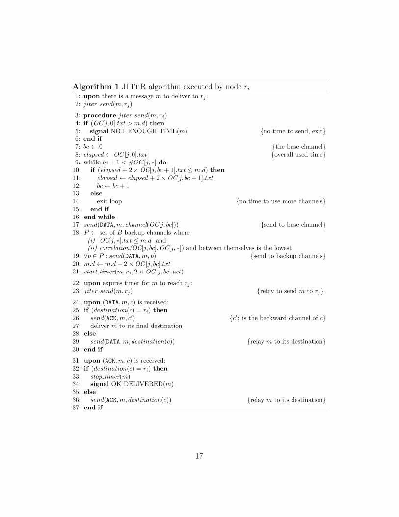
Algorithm 1 contains the pseudo-code executed by node ri when a mes-sage m = 〈data, d〉 is to be sent to node rj. The algorithm uses primi-tive send(TYPE,m, c) to transmit message m of type TYPE through an over-lay channel c (TYPE is one of DATA or ACK). The destination node is im-plicit in c, and can be obtained with function destination(c). Functionchannel(OC[j, i]) returns the overlay channel of the corresponding entry ofOC, while function correlation() gives the correlation between the routes oftwo OC entries. The number of channels in an OC matrix row j is denotedby #OC[j, ∗]. The deadline of message m relative to the instant in whichthe message was sent is in the field m.d.
The main part of the algorithm is in procedure jiter send (Lines 3-21).This procedure is executed in two cases: (i) when ri receives a message mto be transmitted through the WAN (Lines 1-2); (ii) when the timer that isstarted when the message is sent (Line 21) expires (Lines 22-23). Node rifirst checks if the fastest channel has a TXT low enough to allow the messageto be received before the deadline, i.e., if TXT is at least equal to the timeavailable to send the message (Line 4). If the TXT is not low enough, anerror signal is raised (Line 5).
Otherwise, the algorithm will find the base channel by testing the OC[j, ∗]entries in ascending TXT order (Lines 7-16). The algorithm predicts themaximum possible number of future retransmissions of m through differentbase channels based on the reference deadline value m.d. It progressively
16
Algorithm 1 JITeR algorithm executed by node ri1: upon there is a message m to deliver to rj :2: jiter send(m, rj)
3: procedure jiter send(m, rj)4: if (OC[j, 0].txt > m.d) then5: signal NOT ENOUGH TIME(m) {no time to send, exit}6: end if7: bc← 0 {the base channel}8: elapsed ← OC[j, 0].txt {overall used time}9: while bc + 1 < #OC[j, ∗] do
10: if (elapsed + 2×OC[j, bc + 1].txt ≤ m.d) then11: elapsed ← elapsed + 2×OC[j, bc + 1].txt12: bc← bc + 113: else14: exit loop {no time to use more channels}15: end if16: end while17: send(DATA,m, channel(OC[j, bc])) {send to base channel}18: P ← set of B backup channels where
(i) OC[j, ∗].txt ≤ m.d and(ii) correlation(OC[j, bc],OC[j, ∗]) and between themselves is the lowest
22: upon expires timer for m to reach rj :23: jiter send(m, rj) {retry to send m to rj}
24: upon (DATA,m, c) is received:25: if (destination(c) = ri) then26: send(ACK,m, c′) {c′: is the backward channel of c}27: deliver m to its final destination28: else29: send(DATA,m, destination(c)) {relay m to its destination}30: end if
31: upon (ACK,m, c) is received:32: if (destination(c) = ri) then33: stop timer(m)34: signal OK DELIVERED(m)35: else36: send(ACK,m, destination(c)) {relay m to its destination}37: end if
17
takes advantage of the distinct overlay channels available in the entries ofOC, each of which with latency cost OC[j, ∗].txt. The algorithm chooses asbase channel the one with the highest TXT , from those that in principleallow the transmission of the message , and sends the message through thatchannel (Lines 17).
Next, a set P of B backup channels is created (Line 18). Backup channelssatisfy two conditions: (i) they expectedly allow the delivery of m before itsdeadline; and (ii) they have the lowest correlation with the base channeland between themselves. The message is sent through the backup channels(Line 19), and then the algorithm updates the message deadline and starts atimer (Lines 20-21). If the timer expires, the message is resent (Lines 22-23).Notice that the message can be resent without need due to a late ACK, butthis is not problematic4.
When the node receives a DATA message m, it either delivers it to itsfinal destination in the LAN, sending an ACK to the sender node (Lines 26-27), or relays m to its destination JITeR node (Line 29), depending on itsdestination. If ri receives an ACK message from node rj, the timer is stoppedand the algorithm terminates with success (Lines 33-34). Notice that theerror signaled in Line 5 can be pessimistic, as the message may be deliveredbut the acknowledgment lost or received later, after the signal is raised.
3.5. Properties
The main property that the algorithm guarantees is timely message de-livery with high probability, despite communication timing faults. Considerthat bc is the index of the base channel (starting with 0) when a message mis first transmitted (Algorithm 1, Line 17) and that B is the number of addi-tional backup channels used on each try (Line 18). The algorithm transmitsm through 1 +B diverse channels in each try (execution of jiter send), andat most bc+ 1 tries are executed to send m. It means that the system toler-ates at most (1 + B)× (bc+ 1)− 1 communication timing faults on overlaychannels. This expression reflects the main idea of JITeR: to explore spaceand time redundancy to increase the probability of timely message transmis-sion. Naturally, the effectiveness of the redundancy employed is dependent
4Instead of setting the timeout to 2×TXT , line 21 might add to that value four timesan estimative of the deviation, similarly to what is done for TCP’s retransmission timer[42]. However, this would waste time that could be used to resend the message through adifferent channel and improve the chances of reception on time.
18
on the characteristics of the network. If the network is very unstable (thechannels’ TXT estimates do not reflect the actual transmission times) and/orif the links exhibit a high correlation, neither JITeR nor any other routingstrategy can effectively ensure timely communication. However, given ISP di-versity and considering the natural redundancy of well-engineered networks,our algorithm will explore both quite effectively, even under harsh scenariosof disasters or DDoS attacks, as we show in Section 5.2.
3.6. An Example
This section presents an example to show: (1) the way a JITeR nodeselects channels to transmit a message; (2) that bad channels are not used;and (3) that load balancing is achieved and the best channels are left forthe messages with shortest deadline. We consider an overlay with four nodes{ri, rj, rk, rl} and B = 1. Node ri is connected to two ISPs, p and q, and sendstwo messages m1 and m2 to node rk in a row, with deadlines respectively of30ms and 70ms. Figure 3 represents the line of the OC matrix with channelsconnecting ri to rj (line j of Figure 2). Each column corresponds to a channel.The channel id was added to help our explanation.
Message m1 has a deadline of 30ms. Lines 7-16 of the algorithm concludethat to send m1 there is time to use channels 0 and 1 (2× 11 + 8 ≤ 30), butnot channel 2 (2 × 14 + 2 × 11 + 8 > 30). Therefore, the first base channelused for m1 is channel 1. For backup channel it chooses the less correlatedchannel that allows achieving the deadline, channel 5, which has correlations = 0.33 with channel 1. Channel 9 is excluded because its TXT is toohigh. If an acknowledgment is not received until 2× TXT 2 = 22ms, then ripicks the second base channel (channel 0) and another backup channel andretransmits the message.
For m2 something similar happens. The deadline is 70ms, so it has timeto use channels 0 to 2 (2× 14 + 2× 11 + 8 ≤ 70), but not channel 3, so thefirst base channel is 2. For backup channel it chooses among channels 1, 3,7 and 9, all with correlation s = 0.5 with channel 2.
This example shows how nodes select channels. It also demonstratesthat bad channels are never selected (channel 9 is never selected to sendm1). Finally, it shows load balancing in action: the two messages are sentthrough different base channels the first time they are sent. Its is importantto recall that the OC matrix is quite dynamic: our aggressive monitoringstrategy ensures that the values of this table (and the order of the channels)
Figure 3: Line of the OC matrix at Jiter node ri with the channels connecting itto rj .
are constantly being updated, ensuring the system adapts to changes in thenetwork conditions.
4. JITeR Implementation
Current implementation. We implemented the JITeR nodes in Java (around6000 lines of code). The prototype uses the JGroups toolkit5 to manage mem-bership, i.e., to keep and update views of the JITeR nodes that are active.The prototype uses the functions of that toolkit to allow nodes to enter thegroup of JITeR nodes, to leave that group, and to be removed automati-cally in case they become inaccessible, similarly to membership services inthe literature [3]. Otherwise the prototype does not use the communicationprimitives provided by JGroups, but sends messages on top of UDP. Theprototype also implements the Flooding and Primary-Backup strategies (seeTable 1).
In normal operation the nodes constantly monitor the TXT betweenthemselves, either explicitly by sending heartbeat messages, or implicitly bymeasuring the time taken to get replies to the data messages they send. Thediversity among channels is periodically assessed using information aboutrouters obtained using traceroute.
Scalability and node replication. The JITeR node of a facility can be repli-cated to cope with more messages (scalability) and to tolerate faults. Thebasic idea is to replicate each JITeR node in a set of hosts in the same
5http://www.jgroups.org/
20
Strategies Technique Basic idea Reference
Best-Path OV Send message through the best overlay channel. In case of fail-ure, retransmit message at most 3 times using a timeout of 3seconds using the best overlay channel.
RON [4]
JITeR0 OV/MH JITeR without backup channels. This work
JITeR1 OV/MH JITeR with 1 backup channel. This workFlooding OV/MH Send message a single time using all available overlay channels. N/AMulti-Path OV Send message through 2 overlay channels: the direct channel and
a randomly chosen overlay channel (direct or not).Mesh-routing [49]with variationin [6]
Hybrid OV Send message through one direct channel. If failure, send mes-sage via 4 randomly chosen overlay channels (direct or not).
SOSR [25]
Round-Robin MH Send message in a circular fashion alternating among all existentaccess links. Retransmit 3 times at most using a timeout of 3seconds.
N/A
Primary-Backup MH Send message always through one specific access link until itfails. In case of failure and if there are redundant links, pickanother one. Retransmission scheme as RR.
Used in the Ital-ian backbone
Table 1: List of the strategies evaluated. OV and MH means that an overlay ormultihoming are used.
geo-location. Each replica handles a fraction of the messages and availabilityis ensured by the other replicas if some of them crash.
The implementation is basically the following. Each replica has soft statereflecting cached data structures that are maintained in a coordination ser-vices such as Zookeeper [28]. The membership (list of replicas) of each nodeis also kept in Zookeeper, that can trivially detect replica failure and supportreplica addition and removal.6 All replicas will monitor different channels ofthe network in order to update the data structures on Zookeeper, and willread this matrix to memory periodically (e.g., every few seconds). A clientthat wants to send a message using such replicated node will choose one ofthe replicas randomly and use it as its JITeR node. The same thing hap-pens when other JITeR nodes want to use this node as a relay. This solutionallows scaling up as long as Zookeeper is not the bottleneck, which is unlikelyas it scales well with the number of read operations [28].
Access and admission control. JITeR improves the timeliness of control traf-fic that we assume to be negligible in comparison to the overall networktraffic. However, in practice access control and admission control have tobe implemented to limit, respectively, who can send messages using JITeRand how much traffic can be sent. There are several options to implementboth mechanisms. For instance, access control can be based on SOCKS5 andadmission control similar to ATM’s [16].
Table 2: Analytical comparison of the algorithms. Refer to Table 1 for the evaluatedalgorithms descriptions (#ch is the number of overlay channels available).
5. Evaluation
This section evaluates JITeR analytically, using simulations, and exper-imentally. These three evaluations complement each other and shed light onthe fundamental characteristic of JITeR and related strategies.
5.1. Analytical Comparison of Strategies
This section compares analytically JITeR with other potential candi-dates to improve the timeliness of control traffic in wide-area IP networks,whether with overlays, multihoming or both. Table 1 describes the strategies,where we consider two possible configurations for JITeR: using B = 0 orB = 1 backup overlay channels, dubbed JITeR0 and JITeR1, respectively.Results are not presented for higher numbers of backup channels because ourexperiments have not shown benefits in relation to JITeR1.
The various strategies can be roughly characterized in terms of three met-rics: the number of times they can resend messages; the number of channelsthey use (overlaying); and the number of access ISPs they exploit (multi-homing). Notice that these numbers are not constant, as they depend on theactual physical configuration of the network (e.g., the number of ISPs) andthe runtime conditions (e.g., the message deadlines and the channels’ TXTactually define how many retransmissions are possible in JITeR). In anycase, it is still possible to calculate a level of fault tolerance of each strategy:the number of faulty channels (channels that are interrupted or with veryhigh delay) and access ISPs that are tolerated. These metrics mean thatif that number of channels or ISPs fail altogether it is still possible for amessage to be received in time, because there is still redundancy in the sys-tem (assuming that failures are independent). They do not mean that themessage will actually be received because they disregard temporary issues,
22
like short duration congestion that can affect the other channel/ISP and de-lay the message. It is also possible to obtain values of cost in terms of thenumber of extra messages transmitted.
These metrics and numbers are shown in Table 2. The symbol # means“number of” and bc is the index of the base channel when the message isfirst transmitted (Algorithm 1, Line 17), which gives the number of timesthe message can be sent through base channels minus one. Notice that #Re-sends accounts for tries to resend the message; for instance JITeR resendsa message up to bc times. Briefly, the table was obtained the following way.The 3rd to 5th columns come from Table 1. The number of faulty channelstolerated (6th column) is equal to the number of channels used (4th column)minus 1. The number of faulty access ISPs tolerated (7th column) is thenumber of ISPs used by the scheme (5th column) minus 1. The cost withno faults (8th column) is the number of packets sent without faults (e.g.,JITeR1 always sends two packets per application-level message and flood-ing sends as many as the number of channels). With omissions this numberincreases (9th/10th column).
The table clearly shows that JITeR1 and JITeR0 explore all the di-mensions of diversity, considering time, channel and access ISP redundancy.This suggests that they are able to achieve better timeliness than alternativeschemes that do not explore all those options. Flooding exploits channel andISP redundancy to the extreme, with the associated high cost of transmit-ting messages through all available channels (#channels). The Best-Path,Multi-Path and Hybrid strategies explore time and/or channel redundancywithin a single ISP. Round-Robing and Primary-Backup explore time andISP redundancy, but not channel redundancy through other facilities.
5.2. Scenario-based Simulation: Critical Information Infrastructure
This section presents a simulation-based evaluation of the strategies de-scribed in Table 1 using a model of a real-world critical information infras-tructure. We developed a detailed model of the Italian power grid GDIIusing information publicly available [18, 47]. We opted for simulation be-cause it would be virtually impossible to have access to any GDII productionenvironment.
The evaluation aims to answer two important questions: (1) Given aset of messages with different deadlines, to what extent are these messagesreceived in time when employing the various strategies? (2) What are thetransmission costs incurred by these strategies?
23
Simulated network environment. Simulations were carried out on the J-Simsimulator7. The simulated network is based on a ISP backbone topologythat is used by the largest Italian power grid company for control communi-cation [47]. This topology is composed of 31 routers and 51 direct channels,as depicted in Figure 4(a). Each router is capable of pushing data at 1Gbps, and network channels provide a propagation delay of 50ms. To rep-resent multihoming, we replicate the network topology to create two fullydecoupled ISP backbones.
(a) Italian ISP topology [47]. (b) Simulation topology.
Figure 4: ISP network topology: reality and simulation.
On the underlying network topology, we considered 17 candidate gate-ways (the polygons in Figure 4(b)), each corresponding to an Italian region.Gateways are located at a control center (CC) or a substation (SS), and theycan send data at 100Mbps. Four special gateways (circles in the figure) arelocated in the main Italian cities in different regions. They connect regionalremote controller stations, thus being responsible for passing along all traffic
7http://sites.google.com/site/jsimofficial/.
24
related to them (e.g., receive monitoring data from various SSs and transmitcommands to reconfigure a SS). The remainder gateways (squares in the fig-ure) are in charge of traffic relative to a SS (e.g., signaling messages sent bythe SS to the respective CC). The gateways correspond to the JITeR nodes, but they can run any of the strategies of Table 1. To limit the number oftransmitted messages, we used only 7 of the 17 gateways in the simulations:the 4 CCs and 3 other well positioned nodes (dark squares in Figure 4(b)).Every node had access to the WAN through two redundant links, each oneprovided by a distinct ISP.
Workload. The traffic of each CC and SS nodes involved in the setup wasgenerated separately. We created 17 different traffic sources with the sameduration of a simulation, totalizing 90,134 messages sent. The same trafficsources were used in all strategies.
The workload was generated based on information about typical powercontrol traffic [18]. Traffic can be periodic or sporadic and have differentdeadlines, according to the type of operation. Five distinct traffic patternswere identified, as shown in Table 3. All these patterns are applied in thesimulation, with periodic messages starting to be sent after a random initialdelay.
Message Deadline Period Description
CC-STATE 4s 4s CCs state info exchangeSS-STATE 1s 2s SS state info to its CCSS-ALARM 1s sporadic SS alarm to its CCCC-CMD 2s sporadic CC command to a SS
CC-HPCMD 1s sporadicCC high-priority com-mand to a SS
Table 3: Power control messages of the simulation.
Faultloads. The faultloads were generated for the simulation interval of 5hours. A faultload has a total number of faults f = 148 to be injectedacross all network components. Faults are injected in backbone routers, linksand gateway interfaces (to emulate the effect of a failure on the ISP accessrouters). A fault number fc was defined for each component class, followingthe distribution of unplanned ISP IP backbone failures shown in [35].
• Faultload 1 (fault-free). Ideal, no failures.
25
• Faultload 2 (accidental faults). A scenario where there are accidentalproblems in the WAN. Accidental faults are generated using a combi-nation of three network failure models from the literature. The modelin [35] is used to determine the failure starting time and localizationper network component, and the failure duration is based on the mod-els in [14, 34]. The resulting model states that (1) the starting timeof failures is randomly picked following a Weibull distribution over thenetwork-wide simulated time window [35]; (2) 30% of all failures lastmore than 30 seconds according to a Pareto truncated distribution [14],while the remainder ones last up to 30 seconds following an Exponen-tial distribution [34]; (3) for each class of network devices, an individualelement is selected according to a Power-Law based distribution [35] toinject the fault.
• Faultload 3 (crisis). A more stringent scenario where the WAN is sub-ject to accidental and malicious faults. This faultload is similar tofaultload 2, but it also includes faults that have a longer duration andaffect more components to simulate DDoS attacks. After analyzingdata about real DDoS attacks in the literature [29, 36], a model wasbuilt with the following characteristics: (1) the initial time of a singlefailure is obtained by uniformly selecting a random number within thesimulation interval; (2) 80% of all failures last more than 30 secondsaccording to a Pareto truncated distribution, and the remainder 20%last up to 30 seconds following an Exponential distribution; (3) for eachclass of network components, an element is uniformly chosen for faultinjection.
Simulation results. Table 4 shows the results of the simulations. Two met-rics are used to evaluate the strategies of Table 1 in the simulations: thenumber of missed deadlines, which is a measure of the effectiveness of thescheme to achieve timely communication; and the percentage of extra mes-sages sent, which is a measure of cost. This last metric is the total numberof messages sent by the scheme minus the number of messages transmittedby the application, divided by the number of messages sent.
The table shows that there were no deadlines missed in the simulations ofany of the strategies in the failure-free (FF) scenario. However, a few of theschemes incurred in additional costs in terms of extra messages. Not surpris-ingly, Flooding was the most expensive scheme, as it sends messages through
26
StrategyMissed deadlines % of extra messages sentFF AF C FF AF C
Table 4: Simulation results in terms of missed deadlines (effectiveness) and % extramessages sent (cost) considering fault-free (FF), accidental faults (AF) and crisis(C) scenarios.
all channels. Its cost was several orders of magnitude higher than those ofJITeR0 and JITeR1. However, on the contrary of JITeR, Flooding doesnot need to keep information about the transmission time of the overlaychannels, so there is a tradeoff involved. Comparing our strategies with theothers, one can conclude that applying an additional backup channel im-plied an increase in the overhead, since JITeR1 duplicates each transmittedmessage by always exploring the backup channel (like Multi-Path). JITeR0
does not use a backup channel, so the cost is negligible.When accidental faults (AF) are considered, we observe that the Hybrid
algorithm had the highest amount of deadlines missed. Flooding missedno deadlines, but also did not JITeR0 and JITeR1 at much lower costs.Interestingly, the non-overlay primary-backup scheme that is used by mostGDIIs outperformed some of the overlay strategies, confirming that often itcan cope with accidental fault scenarios.
In the crisis (C) scenario the non-overlay Round-Robin scheme exhibitedthe highest number of deadlines missed: 9,600 out of 90,134, which is morethan 10%. Similarly to the previous scenario, Primary-Backup had betterefficiency at a lower cost than both Hybrid and Multi-Path. Flooding had asmall number of deadlines missed (5), which shows that there were cases inwhich it was impossible to mask all faults (there were network partitions).When our solution was employed without backup channels (JITeR0), itmissed 97 deadlines, which is about 1% of the missed deadlines by the RRscheme (the worst performing strategy) and 6% of those missed by BP (the
27
Figure 5: Number of messages delivered by JITeR1 and Best-Path (RON) perrange of latencies (faultload 3; log scale).
best strategy excluding our solution and flooding). These percentages de-crease further with JITeR1 since it adds one backup channel to the basicscheme – here, the fraction is about 0.4% of the missed deadlines by RR and2.4% of those missed by Best-Path (i.e., RON).
The results for missed deadlines of JITeR are not as good as flooding’s inthis scenario, but the cost of the latter is much higher. The JITeR approachallows a tradeoff by setting the number of backup channels, as shown by theimprovement from JITeR0 (no backups) to JITeR1 (one backup) from 97to 37 missed deadlines.
Just as observed with fautload 2, JITeR had a higher overhead thansome other strategies. However, even though Multi-Path and Hybrid explorethe spatial redundancy as JITeR1, they could not exhibit the same progressin terms of reducing the number of missed deadlines. The difference comesfrom the overlay channel selection algorithm employed by our strategy.
Best-Path either delivers the messages in the initial 0.2s interval or toolate. JITeR1 instead does not try to achieve the best latency, so only abouthalf of the messages are delivered in the first 0.2s, and the rest is distributedover the bins, but it delivers more messages on time.
Figure 5 compares in more detail the behavior of JITeR1 and Best-Path(BP) in the crisis scenario (Faultload 3). Recall that the BP strategy aims tominimize the communication latency by picking the channels with the lowestTXT to send the messages. Notice that the y-axis is logarithmic and that
28
this figure only displays data for messages with deadlines of 2 seconds. Thegraph shows the number of messages that arrived with different latencies tothe destination using bins with size of 0.2s. It can be observed that Best-Path either delivers the messages in the initial 0.2s interval or too late (1,527messages miss the deadline of two seconds). JITeR1 instead does not tryto achieve the best latency, so only about half of the messages are deliveredin the first 0.2s, and the rest is distributed over the bins with increasinglyhigher latencies. However, when compared with Best-Path, JITeR1 onlymisses a few deadlines (37 messages arrive after two seconds), showing thatbeing just-in-time is a better strategy than being early in a utility networkapplication scenario.
5.3. Amazon EC2 Experiments
We run the JITeR prototype in the Amazon EC2 service. We deployed 5nodes (micro instances) in 5 different Amazon AWS regions: Ireland, Tokyo,S. Paulo, Oregon, and N. Virginia. We run experiments continuously foraround 100 hours with more than 55 thousand messages sent. Each node sentmessages to each of the other nodes in round-robin, using JITeR0, JITeR1,Flooding and Primary-Backup, with deadlines of 250ms, 500ms, and 1s. Allmessages had a payload of 1kB. We considered a single access ISP per node,as to the best of our knowledge it is not possible to use multihoming inAmazon EC2.
A difficulty in the experiments is the assessment if a message is received bythe deadline or not. To escape this issue, in the experiments we interpretedthe deadline as being the deadline for the sender to receive an acknowledg-ment of the reception of the message, not for the receiver delivering themessage.
Experimental results. Table 5 summarizes the experimental results. Themain conclusion that can be extracted from the table is aligned with the simu-lations: Flooding, JITeR0 and JITeR1 obtain similar results, with JITeR1
slightly better than Flooding, and this one slightly better than JITeR0.Primary-Backup gives worse results (with 250ms deadlines). Notice thatalthough Flooding uses all overlay channels it does not retransmit the mes-sage, which explains why JITeR1 performs better. In terms of additionalmessages sent the results are almost the opposite: Primary-Backup is thecheapest, very closely followed by JITeR0 – only 19% more messages for avery low number of deadlines missed –, then JITeR1 and Flooding.
Table 6: Average TXT between Amazon EC2 pairs of nodes during the period of theexperiments (in milliseconds). The distances between nodes are rough estimates(in Km).
A second observation is that only messages with deadline of 250ms missthe deadline. To understand this we need to have an idea of the TXT ofthe communication between the nodes during the period of the experiments.This information is provided in Table 6. This table shows clearly that 250msis short for sending and getting back an acknowledgment between the mostfar apart nodes (plus S. Paulo-Ireland).
Path diversity. We wanted to understand the path diversity existing betweenthe 5 Amazon EC2 regions, as diversity is important to tolerate faults thataffect several routes. We ran the lft command between the 5 regions everyhour for two weeks in August 2013. lft is essentially a version of traceroutethat shows the ASs traversed. There were occasional changes but the ISPsand ASs crossed remained mostly constant during that period, so we show
30
From \ To Ireland N. Virginia Oregon S. Paulo Tokyo
Ireland — Tinet (2),Amazon (4)
Tinet (3),Amazon (4)
Level3 (3),Amazon (4)
Level3 (3),BTN (1),Amazon (5)
N. Virginia NTT (2),Telia (3),Amazon (4)
— Amazon (5) NTT (2),Level3 (3),Amazon (2)
Qwest (2),BTN (1),Amazon (4)
Oregon NTT (2),Telia (3),Amazon (4)
Amazon (5) — NTT (1),Level3 (2),Amazon (3)
NTT (3),Amazon (3)
S. Paulo SeaBone (1),Tinet (3),Amazon (3)
SeaBone (2),Amazon (4)
Telefonica(2), NTT(2), Amazon(3)
— SeaBone (2),Tata (1),Amazon (3)
Tokyo NTT (2),Telia (2),Amazon (4)
NTT (3),Amazon (5)
KDDI (4),Amazon (5)
NTT (2),SeaBone (2),Amazon (3)
—
Table 7: ISPs and number of ASs (between parentheses) connecting Amazon’sregions obtained using lft on August 2nd 2013.
data taken at a single day, August 2nd.Table 7 presents the ISPs connecting the nodes deployed in the regions
of Amazon EC2. A first observation is that there is much diversity of ISPsused, 10 for connecting the 5 nodes. A second interesting conclusion is thatthe paths between two nodes are often different depending on the direction.For instance, from N. Virginia to Ireland the path traverses NTT and Telia,whereas from in the opposite direction it crosses Tinet, not NTT or Telia.The network connecting N. Virginia and Oregon (and North California, notshown) has only routers from Amazon.
The diversity of ASs is shown in the same table. The number after eachISP (and Amazon) is the number of ASs of that ISP crossed by the path.The number of ASs varies between 5 and 9. Again this suggests a consider-able level of diversity, creating opportunities for the deployment of overlaysolutions such as JITeR.
5.4. Control Costs
JITeR has some control overhead in relation to the simplest alternativestrategy: flooding. This session evaluates this overhead.
In terms of memory footprint, nodes store two matrices, DC and OC(Section 3.3). Matrix DC stores TXT and rout for every other node overall ISPs. This matrix has an average size provided by the formula in the
31
Cost Formula 5 nodes 17 nodes 50 nodes
Size of MatrixDC at a node
(#Nodes− 1)#ISPs(4 + 4(AvgRouters)) 352 B 1408 B 4312 B
Table 8: JITeR control overhead. #Nodes is the number of nodes. The valueswere calculated considering IPv4, 2 ISPs, average of 10 routers in direct chan-nels (AvgRouters), 3 requests/replies to measure TXT (Rep), and size of thesemessages of 50 B (PingSize).
second row of Table 8, where #Nodes is the number of nodes, AvgRoutersis the average number of routers of a direct channel, 4 bytes is the size ofthe integers that represent TXT , and 4 bytes is the size of IPv4 addressthat represent a router (a public IP address of one of the router’s interfaces).Matrix OC has data about the overlay channels between the node and all theothers (see Figure 2). This matrix has (#Nodes−1)(#Nodes−2)(#ISPs)2
cells that store the same data as the cells of matrix DC, the IP of the relaynode, and the two ISPs. The size of the matrix is shown in the third row ofthe table, assuming a single byte is used to store the identifier of the ISP.
In terms of communication overhead, each node has to measure the TXTand send the DC matrix to all other nodes periodically. This cost is providedby the formula in the last row of the table, where Rep is the number ofmessages sent to measure the TXT to each node (ping), PingSize the sizeof that message, and SizeOfDC the size of the DC matrix at a node (secondrow of the same table). The communication overhead depends strongly onthe period considered; it is higher if the period is short, and smaller if theperiod is long, as already pointed out.
The last 3 columns of the table provide concrete values for the memoryfootprint and the communication overhead. 5 nodes is the number of JITeRnodes we used in the AWS experiments, so it expresses the overheads in thatscenario. Next, 17 nodes is the number used in the simulations of Section 5.2.Finally, 50 nodes is a value that we consider large for this kind of scenario,which we depicted simply to show that the costs are reasonable. Traffic of11 MB (bottom right) may seem considerable, but recall that this is not persecond, but per whatever period is used (e.g., per minute or 10 minutes).Nevertheless, this value grows exponentially with the number of nodes.
32
6. Conclusion
We presented the design and validation of an algorithm, called JITeR(Just-In-Time Routing), which routes deadline constrained messages at ap-plication level, using novel overlay and multihoming channel selection strate-gies, leveraging the natural redundancy of geo-distributed GDII’s networks.
JITeR solves an important problem, of providing real-time message la-tency and reliability assurances for traffic in wide-area networks offering non-differentiated IP services, although not with 100% coverage of the timelinessproperties. Design goals met in our approach, in order to improve its ap-plicability, included: practicality and non-intrusiveness; compatibility withcurrent GDIIs; no wide-area IP network changes; cost consciousness.
Analytical, scenario-based and experimental evaluations with an imple-mentation of JITeR nodes have show the main benefits of JITeR in relationto other approaches. We believe JITeR can be a important contribution tosolving timeliness problems for control traffic in inter-datacenter communi-cation, or distributed control of critical infrastructures.
Acknowledgments
This work was partially supported by the EC through project FP7-607109(SEGRID), Alban scholarship E07D401192BR, and by national funds throughFundacao para a Ciencia e a Tecnologia (FCT) with references UID/CEC/50021/2013 (INESC-ID) and PEst-OE/EEI/UI0408/2014 (LaSIGE). We thankthe anonymous reviewers and Fabrizio Garrone for the discussions and de-tailed information on the Italian power grid in the context of EC projectCRUTIAL.
References
[1] Akella, A., Maggs, B., Seshan, S., Shaikh, A., Sitaraman, R., 2003. Ameasurement-based analysis of multihoming. In: Proc. SIGCOMM’03.
[2] Amir, Y., Danilov, C., Goose, S., Hedqvist, D., Terzis, A., Dec. 2006. Anoverlay architecture for high quality VoIP streams. IEEE Transactionson Multimedia 8 (6).
[3] Amir, Y., Dolev, D., Kramer, S., Malkhi, D., Nov. 1992. Membershipalgorithms for multicast communication groups. In: Proc. 6th WDAG.pp. 292–312.
33
[4] Andersen, D., Balakrishnan, H., Kaashoek, M. F., Morris, R., 2001.Resilient overlay networks. In: Proc. SOSP’01.
[5] Andersen, D., Balakrishnan, H., Kaashoek, M. F., Rao, R., 2005. Im-proving web availability for clients with MONET. In: Proc. NSDI’05.
[6] Andersen, D., Snoeren, A., Balakrishnan, H., Oct. 2003. Best-pathvs. multi-path overlay routing. In: Proc. IMC’03.
[7] Apostolopoulos, J., Wong, T., Tan, W.-t., Wee, S., 2002. On multipledescription streaming with content delivery networks. In: Proc. INFO-COM’02. pp. 1736–1745.
[8] Baker, J., Bond, C., Corbett, J., Furman, J., Khorlin, A., Larson, J.,Leon, J.-M., Li, Y., Lloyd, A., Yushprakh, V., 2011. Megastore: Provid-ing scalable, highly available storage for interactive services. In: Proc.CIDR’11.
[9] Blanchet, M., Seite, V. P., Nov. 2011. Multiple Interfaces and Provision-ing Domains Problem Statement. IETF RFC 6418.
[10] Cinque, M., Di Martino, C., Esposito, C., 2012. On data dissemina-tion for large-scale complex critical infrastructures. Computer Networks56 (4), 1215–1235.
[11] Cisco Systems, 2010. IP Routing: OSPF Configuration Guide, CiscoIOS Release 15.1MT. Cisco Systems, Ch. OSPF Support for Fast HelloPackets, pp. 117–122.
[13] Cui, W., Stoica., I., Katz, R., 2002. Backup path allocation based on acorrelated link failure probability model in overlay networks. In: Proc.ICNP’02.
[14] Dahlin, M., Chandra, B., Gao, L., Nayate, A., 2003. End-to-end WANservice availability. IEEE/ACM Transactions on Networking 11 (2).
34
[15] Dantas, W., Bessani, A., Correia, M., Jun. 2009. Not quickly, just intime: Improving the timeliness and reliability of control traffic in utilitynetworks. In: Proc. HotDep’09.
[16] de Prycker, M., 1995. Asynchronous Transfer Mode: Solution for Broad-band ISDN, 3rd Edition. Prentice Hall.
[17] DeCandia, G., Hastorun, D., Jampani, M., Kakulapati, G., Lakshman,A., Pilchin, A., Sivasubramanian, S., Vosshall, P., Vogels, W., 2007.Dynamo: Amazon’s highly available key-value store. In: Proc. SOSP’07.
[20] Dzung, D., Naedele, M., Hoff, T. V., Crevatin, M., 2005. Security forindustrial communication systems. Proc. of the IEEE 93 (6), 1152–1177.
[21] Esposito, C., Cotroneo, D., Russo, S., Apr. 2013. Survey on reliabilityin publish/subscribe services. Computer Networks 57 (5), 1318–1343.
[22] Esposito, C., Russo, S., Beraldi, R., Platania, M., Baldoni, R., 2012.Achieving reliable and timely event dissemination over WAN. In: Dis-tributed Computing and Networking. pp. 265–280.
[23] Garrone (editor), F., Jan. 2007. Analysis of new control applications.Deliverable D2, EC Project CRUTIAL, IST-2004-27513.
[24] Gjermundrod, H., Bakken, D. E., Hauser, C. H., Bose, A., 2009. Grid-Stat: A flexible QoS-managed data dissemination framework for thepower grid. IEEE Transactions on Power Delivery 24 (1), 136.
[25] Gummadi, K., Madhyastha, H., Gribble, S., Levy, K., Wetherall, D.,2004. Improving the reliability of Internet paths with one-hop sourcerouting. In: Proc. OSDI’04.
[26] Han, J., Watson, D., Jahanian, F., March 2005. Topology aware overlaynetworks. Proc. INFOCOM’05 4, 2554–2565.
35
[27] Hefeeda, M., Habib, A., Botev, B., Xu, D., Bhargava, B., 2003. Promise:peer-to-peer media streaming using collectcast. In: Proc. of ACM Mul-timedia. pp. 45–54.
[28] Hunt, P., Konar, M., Junqueira, F., Reed, B., Jun. 2010. Zookeeper:Wait-free coordination for Internet-scale services. In: Proc. ATC’10.
[29] Hussain, A., Heidemann, J., Papadopoulos, C., 2003. A framework forclassifying denial of service attacks. In: Proc. SIGCOMM’03.
[30] Iannaccone, G., Chuah, C., Mortier, R., Bhattacharyya, S., Diot, C.,2002. Analysis of link failures in an IP backbone. In: Proc. IMW’02.
[31] Igure, V., Laughter, S., Williams, R., 2006. Security issues in SCADAnetworks. Computers & Security 25.
[32] Jain, S. et al, 2013. B4: Experiences with a globally-deployed softwaredefined WAN. In: Proc. SIGCOMM’13.
[33] Katz, D., Ward, D., Jun. 2010. Bidirectional Forwarding Detection(BFD). IETF RFC 5880.
[34] Li, Z., Yuan, L., Mohapatra, P., Chuah, C.-N., 2007. On the analysis ofoverlay failure detection and recovery. Computer Networks 51 (13).
[35] Markopoulou, A., Iannaccone, G., Bhattacharyya, S., Chuah, C., Gan-jali, Y., Diot, C., 2008. Characterization of failures in an operational IPbackbone network. IEEE/ACM Transactions on Networking 16 (4).
[36] Moore, D., Shannon, C., Brown, D., Voelker, G., Savage, S., May 2006.Inferring Internet denial-of-service activity. ACM Transactions on Com-puter Systems 24 (2).
[37] Neves, N., (editors), P. V., Mar. 2009. Architecture, services and proto-cols for CRUTIAL. Deliverable D18, EC Project CRUTIAL, IST-2004-27513.
[38] Nichols, K., Blake, S., Baker, F., Black, D., Dec. 1998. Definition of theDifferentiated Services Field (DS Field) in the IPv4 and IPv6 Headers.IETF RFC 2474.
36
[39] Padmanabhan, V. N., Wang, H. J., Chou, P. A., Sripanidkulchai, K.,2002. Distributing streaming media content using cooperative network-ing. In: Proc. NOSSDAV. pp. 177–186.
[40] Pallis, G., Vakali, A., 2006. Insight and perspectives for content deliverynetworks. Communications of the ACM 49 (1), 101–106.
[41] Pathak, A., Pucha, H., Zhang, Y., Hu, Y. C., Mao, Z. M., 2008. Ameasurement study of internet delay asymmetry. In: Proc. PAM’08. pp.182–191.
[43] Pelsser, C., Cittadini, L., Vissicchio, S., Bush, R., May 2013.On the suitability of ping to measure latency. RIPE 66 Meeting.https://ripe66.ripe.net/presentations/128-130513.tokyo-ping.pdf.
[44] Peng, T., Leckie, C., Ramamohanarao, K., 2007. Survey of network-based defense mechanisms countering the DoS and DDoS problems.ACM Computing Surveys 39 (1).
[45] Rekhter, Y., Li, T., Mar. 1995. A Border Gateway Protocol 4 (BGP-4).IETF RFC 1771.
[46] Romijn, E., Aug. 2010. RIPE NCC and Duke University BGPexperiment, https://labs.ripe.net/Members/erik/ripe-ncc-and-duke-university-bgp-experiment.
[47] Rosato, V., et al., 2007. Final report on analysis and modelling of LCCItopology, vulnerability and decentralised recovery strategies. DeliverableD2.1.2, EC Project IRRIIS.
[48] Segall, L., Nov. 2011. Internet routing glitch kicks millions offline.http://money.cnn.com/2011/11/07/technology/juniper internet outage/?hpt=hp t3.
[49] Snoeren, A., Conley, K., Gifford, D., 2001. Mesh-based content routingusing XML. In: Proc. SOSP’01.
37
[50] Subramanian, L., Stoica, I., Balakrishnan, H., Katz, R. H., 2004.OverQoS: An overlay based architecture for enhancing internet QoS.In: Proc. NSDI’04.
[51] Tran, D. A., Hua, K., Do, T., 2003. Zigzag: An efficient peer-to-peerscheme for media streaming. In: Proc. INFOCOM’03. pp. 1283–1292.
[52] Vamanan, B., Hasan, J., Vijaykumar, T. N., 2012. Deadline-aware dat-acenter TCP (D2TCP). In: Proc. SIGCOMM’12.
[53] Verissimo, P., Rodrigues, L., 2001. Distributed Systems for System Ar-chitects. Kluwer Academic Publishers.
[54] Viddal, E., Abelsen, S., Bakken, D. E., Hauser, C. H., 2007. Ratatoskr:Wide-area actuator RPC over GridStat with timeliness, redundancy,and safety. Tech. Rep. EECS-GS-011, Washington State University.
[55] Watson, D., Jahaniam, F., Labovitz, C., 2003. Experiences withmonitoring OSPF on a regional service provider network. In: Proc.ICDCS’03.
[56] Wilson, C., 2006. Terrorist capabilities for cyber-attack. In: Interna-tional CIIP Handbook 2006. Vol. II. Center for Security Studies, ETHZurich, pp. 69–88.
[57] Wilson, C., Ballani, H., Karagiannis, T., Rowstron, A., 2011. Betternever than late: Meeting deadlines in datacenter networks. In: Proc.SIGCOMM’11.
[58] Xu, H., Li, B., 2013. Joint request mapping and response routing forgeo-distributed cloud services. In: Proc. INFOCOM’13. pp. 854–862.
[59] Zhang, X., Perrig, A., 2010. Correlation-resilient path selection in multi-path routing. In: Proc. of GLOBECOM’10.