JM-1000 ™ Jet-Set Mini-Jet Operating Instructions For 1-1/2” to 3” lines up to 50 ft. long Your JM-1000 Jet-Set electric water jet is designed to give you years of trouble- free, profitable service. However, no ma- chine is better than its operator. Read, understand and follow all safety warnings and instructions provided with the product. Failure to follow the warnings and instructions may result in electric shock and/or serious injury. Save all warn- ings and instructions for future reference. SAVE THESE INSTRUCTIONS!
Transcript
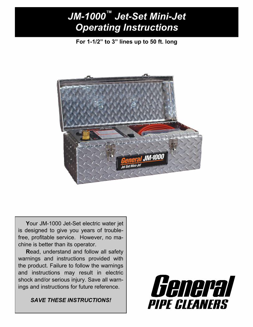
JM-1000™
Jet-Set Mini-Jet Operating Instructions
For 1-1/2” to 3” lines up to 50 ft. long
Your JM-1000 Jet-Set electric water jet
is designed to give you years of trouble-
free, profitable service. However, no ma-
chine is better than its operator.
Read, understand and follow all safety
warnings and instructions provided with
the product. Failure to follow the warnings
and instructions may result in electric
shock and/or serious injury. Save all warn-
ings and instructions for future reference.
SAVE THESE INSTRUCTIONS!
WARNING! Read and understand all instructions. Failure to follow all instructions listed below may result in electric shock, fire and/or serious personal injury. Replacement manuals are available upon request at no charge, or may be downloaded from our website, www.drainbrain.com. Instructional videos are available for download on our website, and may be ordered. If you have any questions or problems, please call General’s customer service department at 412-771-6300.
SAVE THESE INSTRUCTIONS!
SAFETY SYMBOLS
Jet-Set JM-1000™
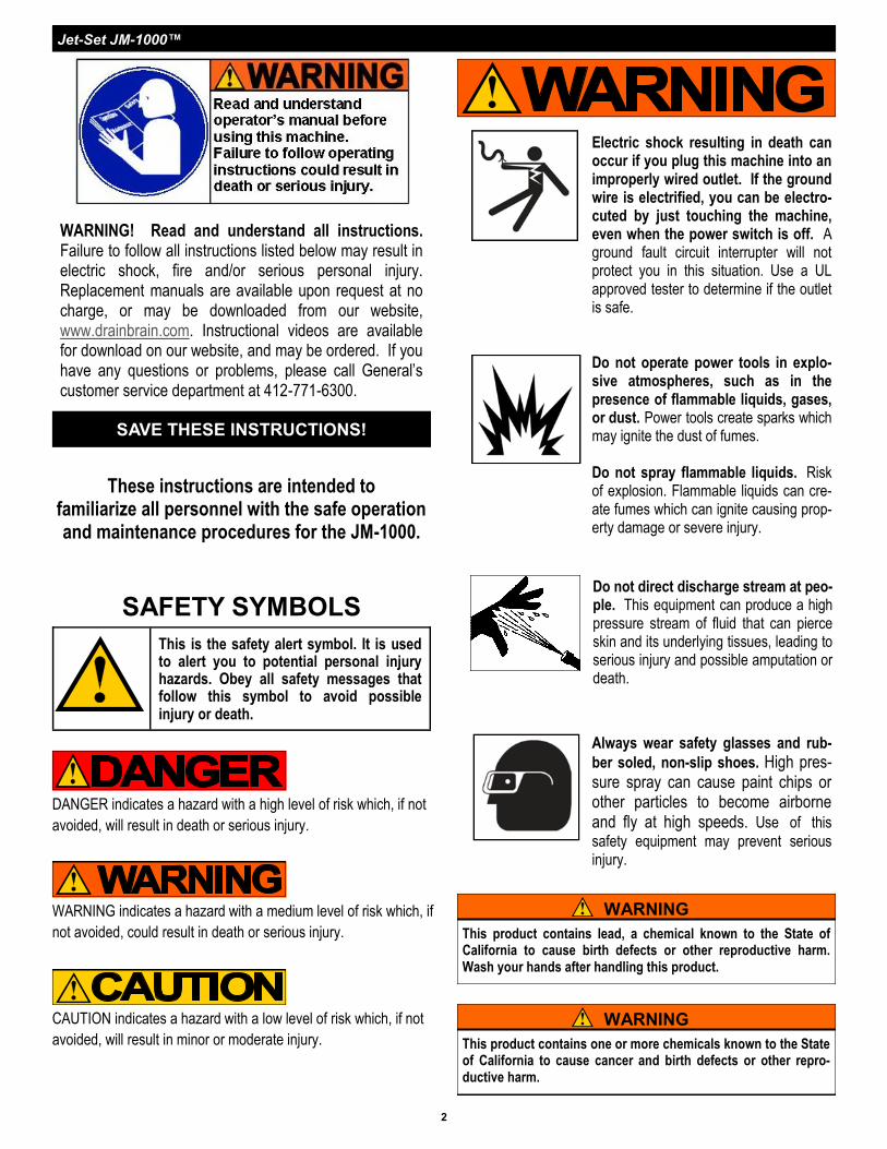
Electric shock resulting in death can occur if you plug this machine into an improperly wired outlet. If the ground wire is electrified, you can be electro-cuted by just touching the machine, even when the power switch is off. A ground fault circuit interrupter will not protect you in this situation. Use a UL approved tester to determine if the outlet is safe.
Do not operate power tools in explo-sive atmospheres, such as in the presence of flammable liquids, gases, or dust. Power tools create sparks which may ignite the dust of fumes. Do not spray flammable liquids. Risk of explosion. Flammable liquids can cre-ate fumes which can ignite causing prop-erty damage or severe injury.
Always wear safety glasses and rub-
ber soled, non-slip shoes. High pres-sure spray can cause paint chips or other particles to become airborne and fly at high speeds. Use of this
safety equipment may prevent serious injury.
These instructions are intended to familiarize all personnel with the safe operation and maintenance procedures for the JM-1000.
DANGER indicates a hazard with a high level of risk which, if not
avoided, will result in death or serious injury.
CAUTION indicates a hazard with a low level of risk which, if not
avoided, will result in minor or moderate injury.
This is the safety alert symbol. It is used to alert you to potential personal injury hazards. Obey all safety messages that follow this symbol to avoid possible injury or death.
WARNING indicates a hazard with a medium level of risk which, if
not avoided, could result in death or serious injury.
Do not direct discharge stream at peo-ple. This equipment can produce a high pressure stream of fluid that can pierce skin and its underlying tissues, leading to serious injury and possible amputation or death.
WARNING
This product contains lead, a chemical known to the State of California to cause birth defects or other reproductive harm. Wash your hands after handling this product.
WARNING
This product contains one or more chemicals known to the State of California to cause cancer and birth defects or other repro-ductive harm.
WORK AREA SAFETY 1. All installations must comply with local codes. Contact your
electrician, plumber, utility company or the selling distributor for specific details. To comply with the National Electrical code (NFPA 70) and provide additional protection from risk of electric shock, the machines are equipped with a UL approved ground fault circuit
interrupter (GFCI) power cord.
2. Risk of explosion. Do not spray flammable liquids or operate in an area where flammable or explosive materials are used or stored. Power tools create sparks which may ignite dust and
fumes.
3. Keep bystanders, children, and visitors away while operating
machine. Distractions can cause you to lose control.
ELECTRICAL SAFETY 1. Grounded tools must be plugged into an outlet, properly in-
stalled and grounded in accordance with all codes and ordi-nances. Never remove the grounding prong or modify the plug in any way. Do not use any adapter plugs. Check with a qualified electrician if you are in doubt as to whether the out-let is properly grounded. If the tool should electrically malfunc-tion or break down, grounding provides a low resistance path to
carry electricity away from the user.
2. Avoid body contact with grounded surfaces such as pipes, radiators, ranges and refrigerators. There is an increased risk
of electric shock if your body is grounded.
3. Do not expose power tools to rain or wet conditions. Water
entering a power tool will increase the risk of electric shock.
4. When operating a power tool outside use an outdoor exten-sion cord marked “W-A” or “W”. These cords are rated for out-
door use and reduce the risk of electric shock.
5. Test the Ground Fault Circuit Interrupter (GFCI) provided with the power cord to insure it is operating correctly before oper-ating machine. Machine must have a properly functioning ground fault circuit interrupter on the power cord. GFCI reduces the risk of
electric shock.
6. Extension cords are not recommended unless they are plugged into a Ground Fault Circuit Interrupter (GFCI) found in circuit boxes or outlet receptacles. The GFCI on the ma-chine power cord will not prevent electric shock from the extension
cords.
7. Only use proper three-wire extension cords in good condition of no more than 50 ft. in length which have three-prong grounding plugs and three-pole receptacles which accept the tools plug. Use of damaged, inferior, or other extension cords will not ground the tool, increases the risk of damage to the machine,
electric shock, bodily injury or death.
8. Keep all electric connections dry and off the ground. Reduces
the risk of electric shock.
9. DO NOT touch plugs or tools with wet hands. Reduces the risk
of electric shock.
GROUND FAULT CIRCUIT INTERRUPTER (GFCI) Your machine is equipped with a ground fault circuit interrupter, which protects you against shock if a short circuit should occur. Check that
receptacle is properly grounded. Test the GFCI before each use.
1. Plug into 120-volt receptacle.
2. Push test button. Indicator light will go out and power to machine
should cut off.
3. If light does not go out when test button is pushed, DO NOT USE
THE MACHINE until proper repairs can be made.
4. To restore power after test, push reset button. With the reset but-ton depressed, if the machine doesn't start, stops while running, or if the operator experiences a mild shock, DO NOT USE THE MA-CHINE! Tag the machine out of service and take it to a motor
repair center or return it to the factory for repairs.
PERSONAL SAFETY 1. High pressure developed by jet machines will cause personal
injury. Water spray should not be pointed at any person. High pressure spray can result in serious injury. If fluid seems to have
penetrated the skin, seek emergency medical attention at once.
2. Grip jet hose or spray wand securely with both hands before starting the machine. Failure to do so could result in injury from a
whipping hose or wand.
3. Always wear eye protection and rubber gloves. Safety equip-ment, eye safety devices, non-skid safety shoes and protective
clothing must be worn when using this equipment.
4. Stay alert, watch what you are doing and use common sense when operating a power tool. Do not use tool while tired or under the influence of drugs, alcohol, or medication. A mo-ment of inattention while operating power tools may result in seri-
ous personal injury.
5. Dress properly. Do not wear loose clothing or jewelry. Con-tain long hair. Keep your hair, clothing, and gloves away from moving parts. Loose clothes, jewelry, or long hair can be caught
in moving parts.
SERVICE 1. Tool service must only be performed by qualified service
personnel. Service or maintenance performed by untrained per-
sonnel could result in injury and damage to the equipment.
2. When servicing tool, use only identical replacement parts. Follow instructions in maintenance section of this manual. Use of unauthorized parts or failure to follow maintenance instruc-
tions may cause injury or damage to equipment.
JET SAFETY 1. Clean nozzles before each use.
2. Flush water supply hose to clear debris before connecting to jet.
3. Flush jet hose to clear debris before attaching nozzle.
4. Do not use hot water. Run only cool water through pump. Do not operate jet above rate pressure or above 90°F (32°C) Operating jet above rate specifications risks damage to the pump
and related components, and will void the warranty.
WARNING
Read and understand all instructions. Failure to follow all in-structions listed below may result in electric shock, fire, and/or serious injury.
SAVE THESE INSTRUCTIONS!
Jet-Set JM-1000™
4
5. Do not operate jet with the output valve in the OFF position for extensive periods of time. This will cause the water to over-
heat and damage the pump.
6. Never run pump without water in it. Operating the machine
without water will cause the pump to fail and void the warranty.
7. Check for worn hose and components before each use. Check that all fittings are secured before using jet. Worn or lose fittings can cause damage to the machine and injure the op-
erator.
8. Protect machine and pump from freezing. Storing or operating the jet in temperatures below freezing can damage pump, hose and other jet components. Store unit indoors or protect with anti-
freeze when not in use.
9. Do not sit or stand on carrying case.
10. General Wire Spring Co. will not be liable for any changes made to our standard machines or any components not pur-chased from General Wire Spring Co.
AUTOMATIC UNLOADER The JM-1000 Mini Jet is equipped with an Automatic Unloader to pro-tect the pump. It prevents pressure overload in the event that the noz-zle is clogged or spray wand trigger is off. A water sensor in the pump will "sense" if the water is flowing and automatically turn off the power off if the water stops flowing to protect the pump from damage. The unit may shut off for 1 - 2 seconds while in operation to allow water to prime the pump. When using the Spray Wand assembly, the Auto-matic Unloader will engage when Trigger is released. Do not run the jet for more than 5 minutes with the pump in bypass mode. Continuing to operate in bypass mode for extended periods will cause damage to the pump. Excessive temperatures will damage the pump and void the warranty.
HOSE GUIDE
Hose Size (ID*) Pipe Size Typical Applications
1/8” (3.175mm) Available in 30’ &
50’ lengths
1-1/2” - 2” (38mm - 51mm)
Small lines, bathroom sinks, tight bends
* Inside Diameter
JET NOZZLES 1. A variety of jet nozzles are available for drain cleaning. Each has a
different spray pattern and purpose. Some nozzles may have an orifice in the front to cut through the stoppage. All will have holes in the back to drive the hose down the line and clean the walls of the pipe. A tight spray pattern (15°) has more driving power for long runs, a wide spray pattern (30°) does a better job of cutting the grease off of the walls of the pipe. A combination of nozzles may be required to clear a line. Always turn off the machine and
turn off output valve before changing nozzles.
2. Make sure the nozzle you are using matches the pump size. A 3000 psi pump requires a different nozzle orifice than a 1500 psi pump. Mismatching nozzles with pump size will either cause too little pressure, which may not clear the drain, or too much pres-
sure, which may damage the machine.
3. Check nozzles before and after each use for clogged holes which can cause pressure to increase to dangerously high levels and damage the pump. A clogged hole can be cleared by simply using
the NCT Nozzle Cleaning Tool.
4. Use the nozzle selection guide to determine what nozzle you will
need for various applications.
JET HOSE When selecting hose size, consider that pressure is lost as the water travels down the length of the hose. As the length increases, the pressure decreases. In addition, the smaller the diameter of the hose, the greater the loss of pressure per foot will be. As an exam-ple, a 2 GPM a 1/4” hose will lose 180 lbs. of pressure over 100 ft. of hose, yet a 3/8” hose will only lose 25 lbs. of pressure over the same length and at the same flow rate. It is important to select the largest possible hose size in order to have as much pressure as possible at the end of the hose.
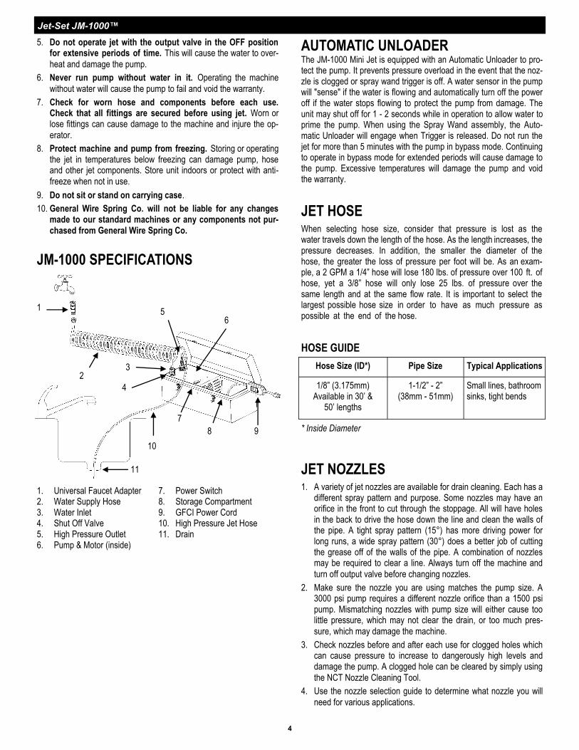
JM-1000 SPECIFICATIONS
1. Universal Faucet Adapter 2. Water Supply Hose 3. Water Inlet 4. Shut Off Valve 5. High Pressure Outlet 6. Pump & Motor (inside)
7. Power Switch 8. Storage Compartment 9. GFCI Power Cord 10. High Pressure Jet Hose 11. Drain
3
5
2
1
10
7
6
8
11
9
4
Jet-Set JM-1000™
5
OPERATION SET-UP
1. Locate the jet near the drain line on a level surface with drainage.
Tip: Ideally, the drain line should be cleared from the downstream
side; that is, from the street back toward the house. If you must
clear the line from the drain toward the street, you may need to
use a siphon pump to clear away excess water.
2. Check the inlet screen to make sure it’s clean before each
use.
3. Check that the incoming water supply is clean and free of debris.
Turn the water source on for at least 15 seconds to remove any
possible debris in the water before connecting hose to water inlet.
4. Connect one end of a water supply hose to the water supply and
the other end to the water inlet of the jet machine. Water supply
must be a minimum of 20 psi and not to exceed 100 psi. or dam-
age to the pump can occur. Use only heavy duty 5/8” hose of no
more than 50 ft. in length. If operated without an adequate
water supply, the pump will cavitate. Cavitation causes the pump
to vibrate, causing damage to the pump. Note: Lack of water
supply can lead to seal damage, causing a loss of pressure
and will void the warranty to the pump.
5. Maximum temperature from the water source should not exceed
90°F (32°C). Using water hotter than 90°F (32°C) can cause
damage to the pump and void the warranty. If jet is being used
to clear ice blockages, see instructions on Ice Blockages.
6. Select the proper hose diameter for the line to be cleaned. When
using a new hose, run water through it to clean it out before at-
taching the nozzle.
NOZZLE SELECTION GUIDE
HOSE SIZE—1/8”
CAT #
15° Rear Jets w/No Forward Jet JN-1
15° Rear Jets w/One Forward Jet JN-2
30° Rear Jets w/No Forward Jet JN-3
Spring Leader JNSL-1
Down Head Nozzle (Optional) JNDH-1
Rotary Nozzle* (Optional) JN-RA-2 JN-RB-2
* Rotary Nozzles can be adapted to 1/8” using AD-3 adapter.
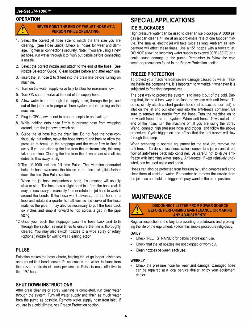
JET ASSEMBLY Upon arrival, inspect the shipping carton for damages. Unbox and
examine all parts. Note any damage to machine or components
for claims against freight carrier.
Jet machines are meant to be used at or near the working area and under operator supervision. If machine must be located out of sight of operator, special controls may be required for proper ma-
chine operation and operator safety
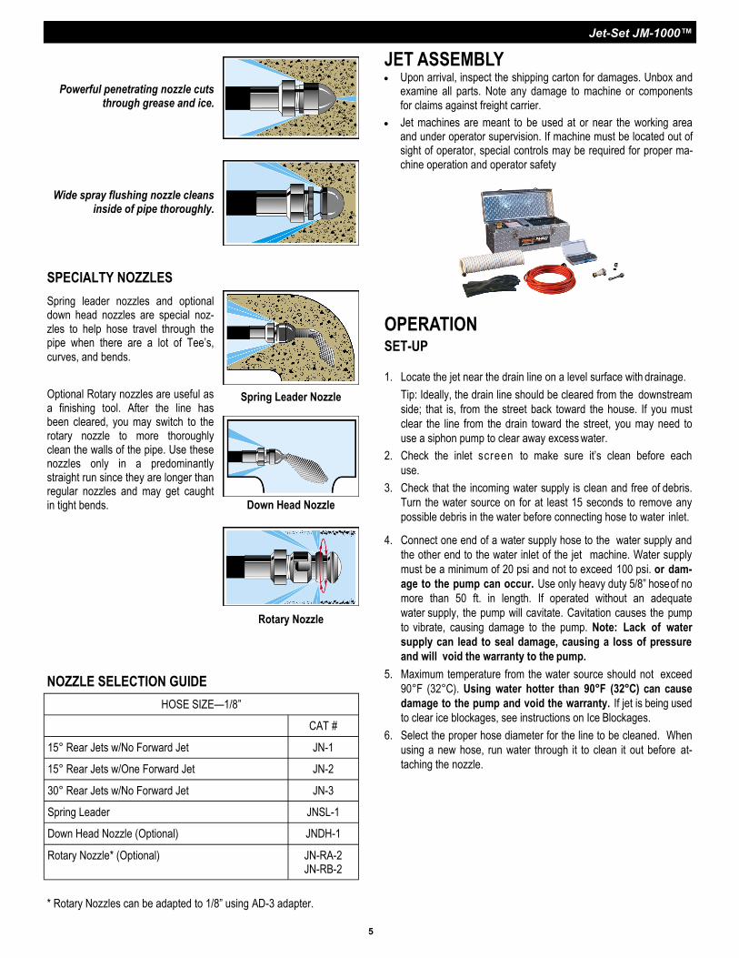
Wide spray flushing nozzle cleans inside of pipe thoroughly.
Powerful penetrating nozzle cuts through grease and ice.
Spring leader nozzles and optional down head nozzles are special noz-zles to help hose travel through the pipe when there are a lot of Tee’s,
curves, and bends.
Optional Rotary nozzles are useful as a finishing tool. After the line has been cleared, you may switch to the rotary nozzle to more thoroughly clean the walls of the pipe. Use these nozzles only in a predominantly straight run since they are longer than regular nozzles and may get caught in tight bends.
Down Head Nozzle
SPECIALTY NOZZLES
Spring Leader Nozzle
Rotary Nozzle
Jet-Set JM-1000™
6
SPECIAL APPLICATIONS ICE BLOCKAGES High pressure water can be used to clear an ice blockage. A 3000 psi
gas jet can clear a 4” line at an approximate rate of one foot per min-
ute. The smaller, electric jet will take twice as long. Ambient air tem-
perature will effect these times. Use a 15° nozzle with a forward jet.
DO NOT allow the incoming water supply to exceed 90°F (32°C) or it
could cause damage to the pump. Remember to follow the cold
weather precautions found in the Freeze Protection section.
FREEZE PROTECTION To protect your machine from severe damage caused by water freez-ing inside the components, it is important to winterize it whenever it is
subjected to freezing temperatures.
The best way to protect the system is to keep it out of the cold. Bar-ring that, the next best way is to flush the system with anti-freeze. To do so, simply attach a short garden hose (not to exceed four feet) to inlet on the jet and put other end into the anti-freeze container. Be sure to remove the nozzle from the hose. Turn the machine on to draw anti-freeze into the system. When anti-freeze flows out of the end of the hose, turn the machine off. If you are using the Spray Wand, connect high pressure hose and trigger, and follow the above procedure. Cycle trigger on and off so that the anti-freeze will flow
through the pump.
When preparing to operate equipment for the next job, remove the anti-freeze. To do so, reconnect water source, turn jet on and direct flow of anti-freeze back into container. Be careful not to dilute anti-freeze with incoming water supply. Anti-freeze, if kept relatively undi-
luted, can be used again and again.
Hoses can also be protected from freezing by using compressed air to clear them of residual water. Remember to remove the nozzle from
the jet hose and hold the trigger of spray wand in the open position.
SHUT DOWN INSTRUCTIONS After drain cleaning or spray washing is completed, run clear water
through the system. Turn off water supply and drain as much water
from the pump as possible. Remove water supply hose from inlet. If
you are in a cold climate, see Freeze Protection section.
PULSE
Pulsation makes the hose vibrate, helping the jet go longer distances
and around tight bends easier. Pulse causes the water to burst from
the nozzle hundreds of times per second. Pulse is most effective in
the 1/8” hose.
1. Select the correct jet hose size to match the line size you are
clearing. (See Hose Guide) Check all hoses for wear and dam-
age. Tighten all connections securely. Note: If you are using a new
jet hose, run water through it to flush out debris before connecting
a nozzle.
2. Select the correct nozzle and attach to the end of the hose. (See
Nozzle Selection Guide) Clean nozzles before and after each use.
3. Insert the jet hose 2 to 3 feet into the drain line before turning on
machine.
4. Turn on the water supply valve fully to allow for maximum flow.
5. Turn ON shut-off valve at the end of the supply hose.
6. Allow water to run through the supply hose, through the jet, and
out of the jet hose to purge air from system before turning on the
machine.
7. Plug in GFCI power cord to proper receptacle and voltage.
8. While holding onto hose firmly to prevent hose from whipping
around, turn the jet power switch on.
9. Guide the jet hose into the drain line. Do not feed the hose con-
tinuously, but rather, move the hose forward and back to allow the
pressure to break up the stoppage and the water flow to flush it
away. If you are clearing the line from the upstream side, this may
take more time. Clearing the line from the downstream side allows
debris to flow away easily.
10. The JM-1000 includes full time Pulse. The vibration generated
helps to hose overcome the friction in the line and glide farther
down the line. See Pulse section.
11. When the jet hose encounters a bend, it’s advance will usually
slow or stop. The hose has a slight bend in it from the hose reel. It
may be necessary to manually feed or rotate the jet hose to work it
around the bends. If the hose won’t advance, put the hose in a
loop and rotate it a quarter to half turn so the curve of the hose
matches the pipe. It may also be necessary to pull the hose back
six inches and snap it forward to hop across a gap in the pipe
fitting.
12. Once you reach the stoppage, pass the hose back and forth
through the section several times to ensure the line is thoroughly
cleared. You may also switch nozzles to a wide spray or rotary
(optional) nozzle for wall to wall cleaning action.
OPERATION
NEVER POINT THE END OF THE JET HOSE AT A PERSON WHILE OPERATING.
MAINTENANCE
Regular inspection is the key to preventing breakdowns and prolong-
ing the life of the equipment. Follow this simple procedure religiously.
DAILY
Check INLET STRAINER for debris before each use.
Check that the jet nozzles are not clogged or worn out.
Clean nozzles between each use.
WEEKLY Check the pressure hose for wear and damage. Damaged hose
can be repaired at a local service dealer, or by your equipment
dealer.
DISCONNECT JETTER FROM POWER SOURCE BEFORE PERFORMING MAINTENANCE OR MAKING
ANY ADJUSTMENTS.
Jet-Set JM-1000™
7
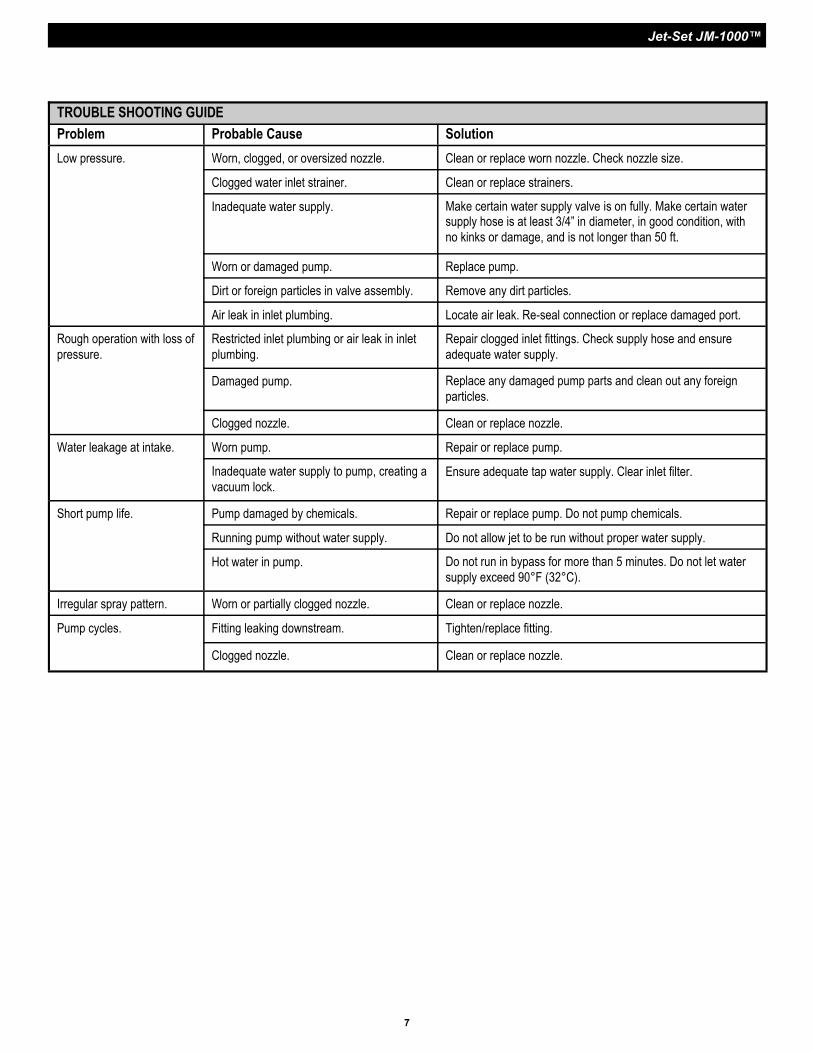
TROUBLE SHOOTING GUIDE
Problem Probable Cause Solution
Low pressure. Worn, clogged, or oversized nozzle. Clean or replace worn nozzle. Check nozzle size.
Clogged water inlet strainer. Clean or replace strainers.
Inadequate water supply. Make certain water supply valve is on fully. Make certain water supply hose is at least 3/4” in diameter, in good condition, with
no kinks or damage, and is not longer than 50 ft.
Worn or damaged pump. Replace pump.
Dirt or foreign particles in valve assembly. Remove any dirt particles.
Air leak in inlet plumbing. Locate air leak. Re-seal connection or replace damaged port.
Rough operation with loss of
pressure.
Restricted inlet plumbing or air leak in inlet
plumbing.
Repair clogged inlet fittings. Check supply hose and ensure
adequate water supply.
Damaged pump. Replace any damaged pump parts and clean out any foreign
particles.
Clogged nozzle. Clean or replace nozzle.
Water leakage at intake. Worn pump. Repair or replace pump.
Inadequate water supply to pump, creating a
vacuum lock. Ensure adequate tap water supply. Clear inlet filter.
Short pump life. Pump damaged by chemicals. Repair or replace pump. Do not pump chemicals.
Running pump without water supply. Do not allow jet to be run without proper water supply.
Hot water in pump. Do not run in bypass for more than 5 minutes. Do not let water
supply exceed 90°F (32°C).
Irregular spray pattern. Worn or partially clogged nozzle. Clean or replace nozzle.