JNCIAJuniper™ Networks Certified Internet Associate
Study Guide - Chapter 9
by Joseph M. Soricelliwith John L. Hammond, Galina Diker Pildush,Thomas E. Van Meter, and Todd M. Warble
This book was originally developed by Juniper Networks Inc. in conjunction with Sybex Inc. It is being offered in electronic format because the original book (ISBN: 0-7821-4071-8) is now out of print. Every effort has been made to remove the original publisher's name and references to the original bound book and its accompanying CD. The original paper book may still be available in used book stores or by contacting, John Wiley & Sons, Publishers. www.wiley.com.
This publication may be used in assisting students to prepare for a Juniper JNCIA exam but Juniper Networks Inc. cannot warrant that use of this publication will ensure passing the relevant exam.
Chapter
9
Multicast
JNCIA EXAM OBJECTIVES COVERED IN THIS CHAPTER:
�
Identify the differences between the operation of a dense-
mode and a sparse-mode protocol
�
Define the reverse path forwarding (RPF) process and
explain its importance
�
Describe the operation of the IGMP protocol
�
Describe the operation of the PIM protocol
�
Describe PIM-SM RP options—static; Auto-RP; bootstrap
router
In this chapter, we examine the concepts and operation of a multicast routing network. You’ll get a high-level view of why we use multicast forwarding, and you’ll learn the basic com-
ponents of a multicast network.We start by taking a look at the special addressing structure for multicast addresses. We fol-
low this with a detailed discussion on how a multicast router prevents forwarding loops. The differences between a dense-mode network and a sparse-mode network are then covered. Next, we examine the details of the Internet Group Management Protocol (IGMP) and how it oper-ates. This includes a look at the capabilities available with each version of the specification. We also discuss the details of the Protocol Independent Multicast (PIM) specification and explain the various methods for electing a rendezvous point.
Next, we show you a configuration example from a sample network operating in the differ-ent multicast modes. Finally, we review some helpful JUNOS software commands you can use to troubleshoot and verify your network.
Multicast Overview
In a networking environment, you have three main methods for transmitting data from one host to another: unicast, broadcast, and multicast. Up to this point in the book, we have been assuming that the data transmissions are unicast in nature. A single source sends a stream of traffic to a single destination. The intervening routers forward the traffic based on the desti-nation IP address encoded in the IP packet.
Both broadcast and multicast follow a one-to-many forwarding paradigm where a single host transmits a single data stream and multiple hosts receive the traffic. The difference between a broadcast and a multicast transmission lies in which hosts process the traffic. A broadcast transmission assumes that all hosts wish to receive the data stream. Each host must process the broadcast packet before deciding if it wants the traffic. Unwanted transmissions are discarded, but the host’s resources (CPU and memory) are wasted in making this decision.
A multicast transmission is also a single stream of traffic, but it assumes that only certain hosts on the network wish to receive the traffic. These hosts request a connection from the net-work, and the intervening routers forward the traffic to just those devices. This concept is very similar to the operation of both television and radio transmissions. The stations send their data (TV show or radio program) into the airwaves. Interested devices tune into the appropriate channel to receive just the programming they desire. Other devices in the same domain need not receive the traffic if they don’t want to—they simply tune to a different channel or turn them-selves off.
Multicast Overview
375
Let’s explore the options for transmitting data to multiple end stations and see why multicast is the best option available.
Unicast Transmissions
In a unicast network, the source of the traffic needs to generate multiple sets of the same infor-mation when it wants to send that traffic to multiple hosts.
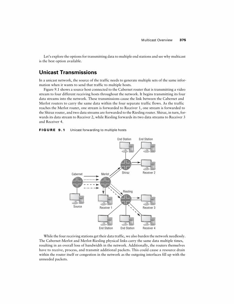
Figure 9.1 shows a source host connected to the Cabernet router that is transmitting a video stream to four different receiving hosts throughout the network. It begins transmitting its four data streams into the network. These transmissions cause the link between the Cabernet and Merlot routers to carry the same data within the four separate traffic flows. As the traffic reaches the Merlot router, one stream is forwarded to Receiver 1, one stream is forwarded to the Shiraz router, and two data streams are forwarded to the Riesling router. Shiraz, in turn, for-wards its data stream to Receiver 2, while Riesling forwards its two data streams to Receiver 3 and Receiver 4.
F I G U R E 9 . 1
Unicast forwarding to multiple hosts
While the four receiving stations get their data traffic, we also burden the network needlessly. The Cabernet-Merlot and Merlot-Riesling physical links carry the same data multiple times, resulting in an overall loss of bandwidth in the network. Additionally, the routers themselves have to receive, process, and transmit additional packets. This could cause a resource drain within the router itself or congestion in the network as the outgoing interfaces fill up with the unneeded packets.
Cabernet Merlot Shiraz
Riesling
Source Receiver 1 Receiver 3
End Station End Station Receiver 4
Receiver 2
End Station End Station
376
Chapter 9 �
Multicast
Broadcast Transmissions
We can easily mitigate the bandwidth and resource problems in the network encountered with a unicast transmission by using a broadcast transmission instead. In this instance, the source host sends a single stream of data traffic into the network, addressed to all possible hosts.
Figure 9.2 shows our same network using a broadcast transmission from the source con-nected to Cabernet. The source PC sends a single stream of traffic into the network, which Cabernet forwards to Merlot. As the traffic is received, Merlot replicates the data into mul-tiple separate streams. A single stream is forwarded to Receiver 1, one stream is forwarded to the Shiraz router, and a third is forwarded to Riesling. Shiraz has multiple hosts connected to it and forwards the traffic to each of them, including Receiver 2. Riesling also forwards the traffic to all of its connected hosts, including Receiver 3 and Receiver 4.
F I G U R E 9 . 2
Broadcast forwarding to multiple hosts
Overall, this system works well for the network. The routers, their links, and their interfaces process each unique data packet only once. We save bandwidth in the network and lessen the resource consumption on the routers. Unfortunately, we introduced another burden. Some end-station devices in the network received and processed the data stream when they didn’t wish to receive it at all. While this may seem like a small consequence, remember that your PC has to expend CPU resource time to discard these unwanted packets. Additionally, we have scalability issues to worry about. As the number of traffic sources grows, the burden on the end stations grows proportionately.
Cabernet Merlot Shiraz
Riesling
Source Receiver 1 Receiver 3
End Station End Station Receiver 4
Receiver 2
End Station End Station
Multicast Addressing
377
Multicast Transmissions
Using a multicast transmission combines the best aspects of both unicasts and broadcasts. We get the network resource savings of the broadcast model while also gaining the end-station resource savings of the unicast model.
Figure 9.3 shows the benefits of using multicast to forward traffic to multiple hosts. Our same host connected to Cabernet is again transmitting the same data stream to the same receiving hosts. Like our broadcast network, the source sends only a single stream of traffic into the network. Cab-ernet forwards the data stream to Merlot, which replicates the packets into multiple streams. Mer-lot forwards one stream to Receiver 1, a second to Shiraz, and a third to Riesling. Shiraz forwards its traffic only to Receiver 2 and not to the other end stations. Riesling, like Merlot, replicates the data stream into two branches. One stream is forwarded to Receiver 3 and the other to Receiver 4.
F I G U R E 9 . 3
Multicast forwarding to multiple hosts
Multicast Addressing
To correctly forward multicast traffic to the appropriate hosts in the network, we need a special set of addressing rules. This allows the network routers to forward and replicate the traffic only where it is needed. In addition, it allows only specific end stations to receive and process the data
Cabernet Merlot Shiraz
Riesling
Source Receiver 1 Receiver 3
End Station End Station Receiver 4
Receiver 2
End Station End Station
378
Chapter 9 �
Multicast
stream. These two requirements are handled by special IP addresses and Ethernet MAC addresses, respectively.
IP Group Addresses
An end station wishing to receive a multicast transmission sends a request to the network that forwards packets matching a specific destination IP address to it. This address is similar to a TV or radio channel and can be requested by multiple hosts. The source station generates the data packets and places this special IP address, called a
group address
, in the destination field of the IP header. Each multicast data stream is uniquely identified by the combination of the traffic source and the group address, represented by the notation (S,G).
When the multicast source is not known, a 0.0.0.0 notation or the wildcard character * replaces the source field. The multicast representation becomes
(0.0.0.0,G), or more commonly (*,G).
The Internet Assigned Numbers Authority (IANA) has reserved a range of address space spe-cifically designed for use with multicasting. Any IP address containing a
1110
in the first four address bits is a multicast group address. In a classful addressing context, this address space is represented by Class D addresses. When you convert the group addresses to a decimal number, the first octet of the address is between 224 and 239. Specifically, the IANA multicast range is 224.0.0.0 through 239.255.255.255. Figure 9.4 shows the multicast group address in a binary format.
F I G U R E 9 . 4
Multicast group address
As is the case with the address space used for unicast transmissions, certain portions of the multicast group addresses are reserved for special purposes. One such group is all addresses within the 224.0.0.0 /24 subnet. These groups are restricted to a local physical media, which means that a router does not forward the datagram to other portions of the network. We enforce this restriction by setting the Time-to-Live (TTL) field to the value 1.
The group addresses in this range are often referred to as well-known addresses because many applications and routing protocols make use of its capability. Some of the more common addresses used from the 224.0.0.0 /24 subnet are:
224.0.0.1 /32
The 224.0.0.1 /32 address represents all IP hosts on the subnet. Each router and PC connected to the physical media receives the datagram and processes the packet.
0 1
1 1
2 3 4
28 bits
31
1 0 Multicast Group ID
Multicast Addressing
379
224.0.0.2 /32
The 224.0.0.2 /32 address is used to reach all IP routers on the subnet. Only connected routers receive packets addressed to this destination. End-user PCs do not listen for these packets.
224.0.0.5 /32
The Open Shortest Path First (OSPF) routing protocol uses the 224.0.0.5 /32 address to communicate with all OSPF-speaking routers on the subnet.
224.0.0.6 /32
OSPF also uses the 224.0.0.6 /32 group address. The designated router and backup designated router receive packets addressed to this destination.
224.0.0.9 /32
Version 2 of the Routing Information Protocol (RIP) uses this address to com-municate with other RIPv2 routers on the subnet.
224.0.0.13 /32
The 224.0.0.13 /32 group address is specifically used by multicast-speaking routers. All devices operating version 2 of the Protocol Independent Multicast (PIM) protocol receive packets addressed to this destination.
224.0.0.18 /32
The 224.0.0.18 /32 group address is used by routers operating the Virtual Router Redundancy Protocol (VRRP). This protocol allows multiple routers to share an IP address on an Ethernet subnet.
224.0.0.22 /32
Multicast-enabled routers also use the 224.0.0.22 /32 group address to com-municate with all devices using version 3 of the Internet Group Management Protocol.
A second address block reserved by IANA is the 232.0.0.0 /8 address space. These addresses are used for
source-specific multicasting (SSM)
, which is supported in version 3 of IGMP. SSM allows an end station to request and receive data streams for a multicast group from a specific source of the traffic. Under normal circumstances, an end host only requests a connection to the group address and it is connected to the metrically closest source of the traffic.
The 233.0.0.0 /8 address space was set aside by IANA to support an addressing scheme known as GLOP. This system provides you with the ability to map an Autonomous System number to a specific set of multicast group addresses, much like an IP subnetting scheme. The AS number is converted to binary and is placed into the middle two octets of the group address. The adminis-trators of the specific AS statically allocate the addresses in the final octet of the group address as needed. The purpose of the GLOP addressing scheme is to easily identify the source autonomous system of multicast traffic using an AS number for control and accounting purposes. While a Juni-per Networks router does not actively monitor and control the use of GLOP multicast addresses, we recommend that you do not use the 233.0.0.0 /8 address range unless you intend to implement GLOP addressing in your network.
The term GLOP is not an acronym, nor is it short for some other term. It is sim-
ply the name given to this method of allocating group addresses.
The final reserved address space we discuss here is the 239.0.0.0 /8 range. These addresses are locally assigned by an administrator and are locally significant to that specific multicast domain. They do not cross the boundaries of the domain. You can think of these addresses as being roughly equivalent to the RFC 1918 addresses for unicast IP traffic; you can use any of the addresses in the range as long as you use them only within domains that you control.
380
Chapter 9 �
Multicast
Please visit
www.iana.org/assignments/multicast-addresses
for a complete
list of reserved multicast addresses.
Ethernet Addresses
As multicast traffic reaches the edge of the network, the router transmits the data stream out each interface where hosts exist that have indicated their desire to receive the traffic. Generally speak-ing, this final transmission is over an Ethernet network where the multicast traffic is encapsulated in a Layer 2 frame. This situation carries with it the possibility of wasting resources on the local subnet. Let’s take a closer look.
In a unicast transmission, the router determines the destination Media Access Control (MAC) address of the end station by using the Address Resolution Protocol (ARP). An ARP request is broadcast onto the Ethernet network, and the appropriate end station responds with its MAC address. The router then forwards the frame using this MAC address as the destination address. Using ARP for multicast is problematic because the potential list of stations wishing to receive the multicast data can change at any time as hosts enter or leave the multicast group. To account for this, the router could perform an ARP on a regular basis. However, the ARP request is a broadcast to the network, and all hosts on the segment must process the packet. Again, this causes a burden on the end stations—the very thing we were trying to avoid. Regardless of how it determines the destination MAC address, when the router sends the data stream to each end station individually, we defeat the purpose of multicast altogether. In the end, we are transmit-ting the data multiple times on the segment.
The basic operation of an Ethernet network means that each end station begins to receive all traffic transmitted on the wire. After interpreting the destination MAC address of the frame, most stations stop receiving the packet altogether. This means that when the router sends the same data multiple times, not only is the bandwidth of the segment wasted but the hosts actually receive por-tions of the data multiple times. To explore this problem in some more detail, suppose that we have four hosts on the Ethernet segment that would like to receive the 224.7.7.7 /32 group address. The router encodes the data into the Ethernet frame, places the MAC address of Receiver 1 in the des-tination field, and transmits the frame onto the segment. All hosts on the network receive the frame, but only Receiver 1 processes the traffic. The router then repeats this process for the other receivers for the first packet of multicast data. This quadruple replication is repeated for each packet in the multicast data stream. Clearly, this is not a good use of our network resources.
To avoid these issues, we have a predefined process for encoding a specific multicast group address within an Ethernet destination MAC address. Once this occurs, the router needs to trans-mit each data packet onto the network only once and each interested end station receives the data only once. Finally, there is no need for the router or the hosts to perform an ARP request.
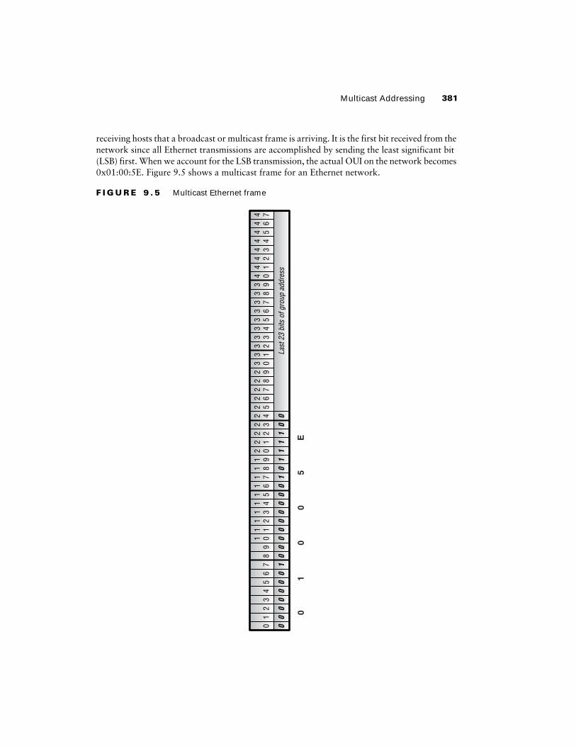
To determine the multicast MAC address for a specific group, we take the last 23 bits of the multicast group address and prepend a single 0 bit to them. These 24 bits now form the lower half of the 48-bit MAC address. The upper half of the address is derived from the assigned orga-nizationally unique identifier (OUI) of 0x00:00:5E. When we use this OUI for multicast on an Ethernet segment, we need to set the Broadcast/Multicast bit to the value 1. This bit alerts
Multicast Addressing
381
receiving hosts that a broadcast or multicast frame is arriving. It is the first bit received from the network since all Ethernet transmissions are accomplished by sending the least significant bit (LSB) first. When we account for the LSB transmission, the actual OUI on the network becomes 0x01:00:5E. Figure 9.5 shows a multicast frame for an Ethernet network.
F I G U R E 9 . 5
Multicast Ethernet frame
01
00
23
45
67
89
1 01 1
1 21 3
1 41 5
1 61 7
1 81 9
2 02 1
2 22 3
2 42 5
2 62 7
2 82 9
3 03 1
00
00
01
00
00
00
00
01
01
11
10
0La
st 2
3 bi
ts o
f gro
up a
ddre
ss
3 23 3
3 43 5
3 63 7
3 83 9
4 04 1
4 24 3
4 44 5
4 64 7
01
00
5E
382
Chapter 9 �
Multicast
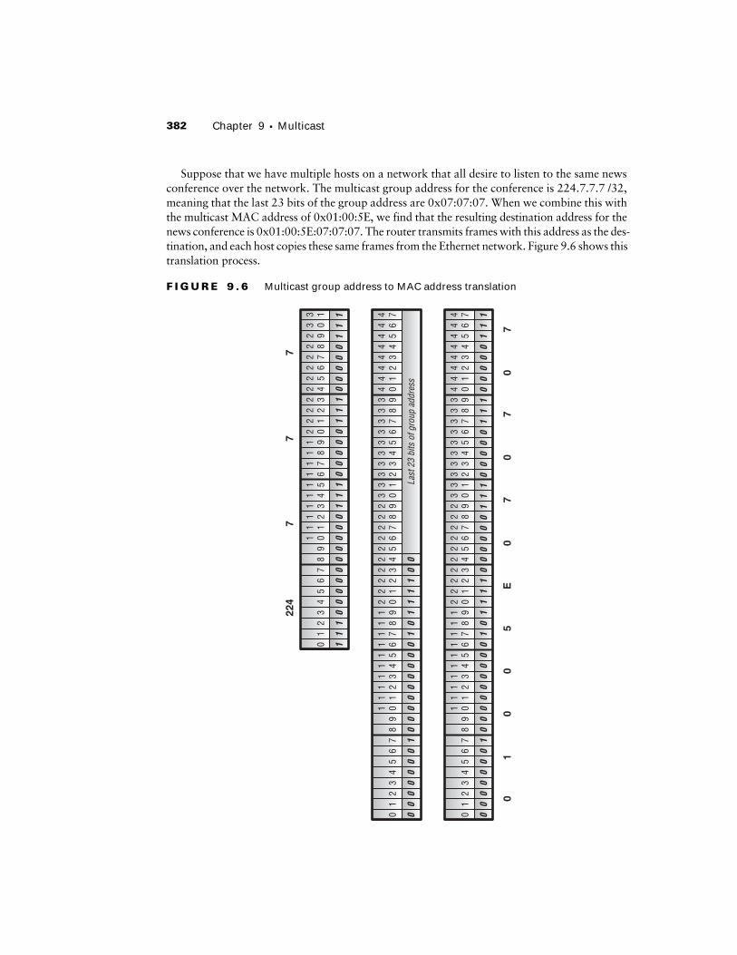
Suppose that we have multiple hosts on a network that all desire to listen to the same news conference over the network. The multicast group address for the conference is 224.7.7.7 /32, meaning that the last 23 bits of the group address are 0x07:07:07. When we combine this with the multicast MAC address of 0x01:00:5E, we find that the resulting destination address for the news conference is 0x01:00:5E:07:07:07. The router transmits frames with this address as the des-tination, and each host copies these same frames from the Ethernet network. Figure 9.6 shows this translation process.
F I G U R E 9 . 6
Multicast group address to MAC address translation
01
00
23
45
67
89
1 01 1
1 21 3
1 41 5
1 61 7
1 81 9
2 02 1
2 22 3
2 42 5
2 62 7
2 82 9
3 03 1
00
00
01
00
00
00
00
01
01
11
10
00
00
01
11
00
00
01
11
00
00
01
11
3 23 3
3 43 5
3 63 7
3 83 9
4 04 1
4 24 3
4 44 5
4 64 7
01
11
23
45
67
89
1 01 1
1 21 3
1 41 5
1 61 7
1 81 9
2 02 1
2 22 3
2 42 5
2 62 7
2 82 9
3 03 1
10
00
00
00
00
01
11
00
00
01
11
00
00
01
11
01
00
23
45
67
89
1 01 1
1 21 3
1 41 5
1 61 7
1 81 9
2 02 1
2 22 3
2 42 5
2 62 7
2 82 9
3 03 1
00
00
01
00
00
00
00
01
01
11
10
0La
st 2
3 bi
ts o
f gro
up a
ddre
ss
3 23 3
3 43 5
3 63 7
3 83 9
4 04 1
4 24 3
4 44 5
4 64 7
01
00
5E
07
07
07
224
77
7
Multicast Forwarding
383
Multicast Forwarding
So far, we’ve discussed the concept of using multicast in a network and explored the options for addressing the data packets. Let’s now begin to focus on how the network itself actually for-wards the data packets from the source to the receivers. We start by examining how to avoid a forwarding loop in the network. We then look at the two methods for transmitting multicast data in a network—dense mode and sparse mode.
Reverse Path Forwarding
The basic function of a router is the examination of an IP destination address and the forward-ing of data to the next-hop router along the path. In a multicast network, this process is not effective because the destination IP address of the packets is the multicast group address. From the perspective of the router, the packets may have to be sent out multiple interfaces. In fact, the default behavior of a multicast router is to forward the data packet out all interfaces except the one where the packet was received. This behavior has the potential for forming a forwarding loop in the network.
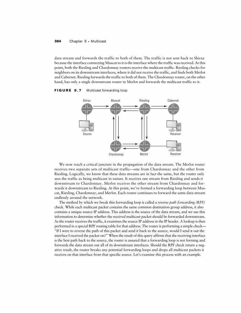
Figure 9.7 shows a multicast source connected to the Shiraz router transmitting a data stream into the network. Shiraz uses the default multicast forwarding mechanism described earlier and sends the traffic to the Muscat router. Muscat has two neighboring routers, so it replicates the
Can I Tune in the Wrong Channel?
A closer examination of how to build an Ethernet frame for multicast traffic might reveal a small problem. The uniqueness of each multicast group address is composed of the 28 bits following the common
1110
of the address range. We use only 23 of those 28 bits, however, in the multicast Ethernet frame. It is theoretically possible that a single host could receive two different multicast streams when it really wanted only one of them.
For example, the last 23 bits of the 230.129.16.1 /32 group address are 0x01:11:01. This is identical to the last 23 bits of the 224.1.16.1 /32 group address. When encoded within an Ethernet multicast frame, the destination MAC address for both groups is 0x01:00:5E:01:11:01. To the network inter-face card (NIC) on the PC, all frames with that destination MAC address are received and pro-cessed by the CPU. Most often, the end user does not notice this problem since the applications themselves won’t use traffic from another stream. However, the back-end resources of the PC are taxed by the extra burden, which might result in a slower response to the user.
The 5-bit difference between the multicast group address and the Ethernet MAC address results in 32 possible address overlaps. In the scope of 268,435,456 possible multicast group addresses, the chance of an overlap occurring on a single Ethernet network is about .00001 percent.
384
Chapter 9 �
Multicast
data stream and forwards the traffic to both of them. The traffic is not sent back to Shiraz because the interface connecting Muscat to it is the interface where the traffic was received. At this point, both the Riesling and Chardonnay routers receive the multicast traffic. Riesling checks for neighbors on its downstream interfaces, where it did not receive the traffic, and finds both Merlot and Cabernet. Riesling forwards the traffic to both of them. The Chardonnay router, on the other hand, has only a single downstream router in Merlot and forwards the multicast traffic to it.
F I G U R E 9 . 7
Multicast forwarding loop
We now reach a critical juncture in the propagation of the data stream. The Merlot router receives two separate sets of multicast traffic—one from Chardonnay and the other from Riesling. Logically, we know that these data streams are in fact the same, but the router only sees the traffic as being multicast in nature. It receives one stream from Riesling and sends it downstream to Chardonnay. Merlot receives the other stream from Chardonnay and for-wards it downstream to Riesling. At this point, we’ve formed a forwarding loop between Mus-cat, Riesling, Chardonnay, and Merlot. Each router continues to forward the same data stream endlessly around the network.
The method by which we break this forwarding loop is called a
reverse path forwarding
(RPF)
check. While each multicast packet contains the same common destination group address, it also contains a unique source IP address. This address is the source of the data stream, and we use this information to determine whether the received multicast packet should be forwarded downstream. As the router receives the traffic, it examines the source IP address in the IP header. A lookup is then performed in a special RPF routing table for that address. The router is performing a simple check—“If I were to reverse the path of this packet and send it back to the source, would I send it out the interface I received the packet on?” When the result of this query affirms that the receiving interface is the best path back to the source, the router is assured that a forwarding loop is not forming and forwards the data stream out all of its downstream interfaces. Should the RPF check return a neg-ative result, the router breaks any potential forwarding loops and drops all multicast packets it receives on that interface from that specific source. Let’s examine this process with an example.
Chardonnay Merlot
Shiraz Muscat Riesling Cabernet
Source
Receiver
Receiver
Multicast Forwarding
385
Figure 9.8 shows our same topology with the same multicast source, which begins to send out multicast traffic to Shiraz. As the traffic is received, Shiraz checks the source IP address of the packets against the RPF table. It finds that the receiving interface is in fact the best path back to the source because it is directly connected to the router. Shiraz then forwards the multicast traffic downstream to Muscat. Again, as Muscat receives the multicast packets, it performs an RPF check. The best path back to the source is through Shiraz, so the traffic is not forming a loop. Muscat forwards the traffic downstream to both Chardonnay and Riesling. The RPF check on both Chardonnay and Riesling finds that Muscat is the best path back to the multicast source, so they also forward the multicast data downstream.
F I G U R E 9 . 8
Reverse path forwarding check
It was at this point in our earlier example that the forwarding loop was formed. Merlot receives two copies of the same multicast data—one from Chardonnay and the other from Riesling. This time, however, the RPF check prevents the loop from forming. Merlot compares the source IP address of the traffic against the RPF table and finds that Chardonnay is the best path back to the source. Merlot begins to drop all multicast traffic from the source it receives on the interface to Riesling and informs the Riesling router to stop sending that particular traffic stream. Since the Chardonnay interface passes the RPF check, Merlot forwards the traffic downstream to Riesling. The data stream received on Riesling’s interface to Merlot is checked against the RPF table. We’ve already determined that the best path from Riesling to the source is through Muscat, so the pack-ets sent by Merlot are dropped from the network. Riesling also instructs Merlot to stop forward-ing the multicast data stream along that link. In the end, no multicast traffic is sent along the link connecting Riesling to Merlot.
The JUNOS software, by default, uses the
inet.0
routing table to perform RPF
checks.
Chardonnay Merlot
Shiraz Muscat Riesling Cabernet
Source
Receiver
Receiver
386
Chapter 9 �
Multicast
Dense-Mode Forwarding
Dense mode
multicast routing protocols assume that every user segment in the network wants to receive the data stream. The type of data forwarding used in a dense-mode environment is very efficient when you know that a large number of receivers exists.
Figure 9.9 shows a network consisting of 10 routers using a dense mode routing protocol. A multicast source is connected to the Shiraz router, and two receivers are currently connected to the group address—one each connected to Merlot and Cabernet. As the source begins transmit-ting data traffic destined for the multicast group address, the routers in the network flood the traffic to each segment in the network. This flooding process follows the rules of the RPF mech-anism for forwarding multicast traffic.
F I G U R E 9 . 9
Dense-mode flooding
A quick look at Figure 9.9 shows that every router in the network doesn’t need to receive the data stream. Only Merlot, Cabernet, and the routers along the path back to the source should be forwarding the traffic. Any router in a dense-mode network may prune itself from the for-warding path by sending a message to its upstream peer. This process occurs for all routers that do not need to receive the traffic.
Figure 9.10 shows the dense-mode prune process. The Chianti router has no connected receiv-ers, so it sends a prune message to Chablis, its upstream neighbor. (Prune messages are discussed in the section “Sparse-Mode Operation” later in this chapter.) The Chablis router also receives a prune message from Bordeaux, its other downstream neighbor. Because both routers downstream
Chianti Chablis Bordeaux Valpolicella
Chardonnay Merlot
Shiraz Muscat Riesling Cabernet
Source
Receiver
Receiver
Multicast Forwarding
387
of Chablis have pruned themselves from the forwarding path, Chablis sends its own prune mes-sage upstream to Chardonnay.
F I G U R E 9 . 1 0
Dense-mode pruning
The
flood and prune
process occurs in a dense-mode network every three minutes (JUNOS software default timer). This ensures that any new hosts arriving on the network begin to receive the multicast traffic during the next flood process. The downside of the flood and prune process is that routers have to explicitly request to stop receiving the data stream when they have no receivers connected downstream. When you have a smaller number of receivers, you also have a larger number of routers pruning themselves from the forwarding path. Hence, a dense-mode net-work is better suited for an environment where almost all connected hosts would like to receive the data stream.
Figure 9.11 shows the end result of a dense-mode flood and prune. This
source-based tree
has the multicast source at the top of a forwarding tree. Each network segment forwarding the traffic forms a branch of the tree while the end-station hosts form the leaves of the source-based tree.
Distance Vector Multicast Routing Protocol (DVMRP), PIM dense mode, and Multicast Open Shortest Path First (MOSPF) all use dense-mode forwarding to
send multicast packets to interested end stations.
Chianti Chablis Bordeaux Valpolicella
Chardonnay Merlot
Shiraz Muscat Riesling Cabernet
Source
Receiver
Receiver
388
Chapter 9 �
Multicast
F I G U R E 9 . 1 1
Source-based tree
Sparse-Mode Forwarding
Sparse mode
multicast routing protocols are exactly the opposite of dense-mode protocols in their assumptions. A sparse-mode multicast network assumes that very few receivers exist for each group address. As such, routers in a sparse-mode network must explicitly request that the data stream be forwarded to them. Additionally, one of the routers in the network performs a special function as a connection point between the source and the receiver. This
rendezvous point (RP)
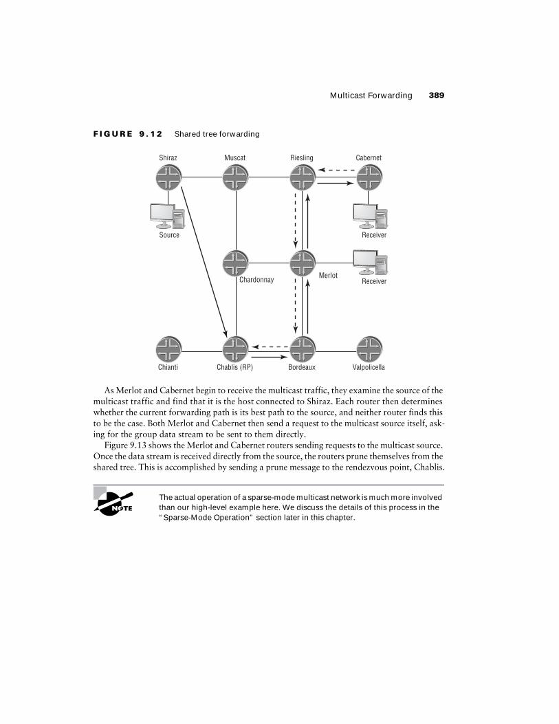
combines knowledge of the group’s source with the requests from the receiver.Figure 9.12 shows our network after we converted to a sparse-mode protocol, with the Chablis
router designated as the RP for the domain. The receivers connected to Merlot and Cabernet request a connection to the multicast group address. This prompts both Merlot and Cabernet to send a mes-sage to Chablis, the RP, requesting that they be added to the forwarding path of the group. Chablis also receives the data traffic from Shiraz, which is connected to the source, through a unicast tunnel. Once the multicast traffic from the source and the requests from the receivers connect at the rendez-vous point, the traffic is forwarded through the network. This
shared tree
has the RP at the top of the forwarding tree with the network segments and receivers as the branches and leaves, respectively. This is often referred to as the rendezvous point tree (RPT) in a sparse-mode network.
Chianti Chablis Bordeaux Valpolicella
Chardonnay Merlot
Shiraz Muscat Riesling Cabernet
Source
Receiver
Receiver
Multicast Forwarding 389
F I G U R E 9 . 1 2 Shared tree forwarding
As Merlot and Cabernet begin to receive the multicast traffic, they examine the source of the multicast traffic and find that it is the host connected to Shiraz. Each router then determines whether the current forwarding path is its best path to the source, and neither router finds this to be the case. Both Merlot and Cabernet then send a request to the multicast source itself, ask-ing for the group data stream to be sent to them directly.
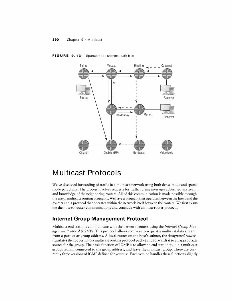
Figure 9.13 shows the Merlot and Cabernet routers sending requests to the multicast source. Once the data stream is received directly from the source, the routers prune themselves from the shared tree. This is accomplished by sending a prune message to the rendezvous point, Chablis.
The actual operation of a sparse-mode multicast network is much more involved than our high-level example here. We discuss the details of this process in the “Sparse-Mode Operation” section later in this chapter.
Chianti Chablis (RP) Bordeaux Valpolicella
Chardonnay Merlot
Shiraz Muscat Riesling Cabernet
Source
Receiver
Receiver
390 Chapter 9 � Multicast
F I G U R E 9 . 1 3 Sparse mode shortest path tree
Multicast ProtocolsWe’ve discussed forwarding of traffic in a multicast network using both dense-mode and sparse-mode paradigms. The process involves requests for traffic, prune messages advertised upstream, and knowledge of the neighboring routers. All of this communication is made possible through the use of multicast routing protocols. We have a protocol that operates between the hosts and the routers and a protocol that operates within the network itself between the routers. We first exam-ine the host-to-router communications and conclude with an intra-router protocol.
Internet Group Management Protocol
Multicast end stations communicate with the network routers using the Internet Group Man-agement Protocol (IGMP). This protocol allows receivers to request a multicast data stream from a particular group address. A local router on the host’s subnet, the designated router, translates the request into a multicast routing protocol packet and forwards it to an appropriate source for the group. The basic function of IGMP is to allow an end station to join a multicast group, remain connected to the group address, and leave the multicast group. There are cur-rently three versions of IGMP defined for your use. Each version handles these functions slightly
Chianti Chablis (RP) Bordeaux Valpolicella
Chardonnay Merlot
Shiraz Muscat Riesling Cabernet
Source
Receiver
Receiver
Multicast Protocols 391
differently, with the newer versions providing more features and functionality. Let’s examine the operation of each in more detail.
The designated router is the router with the lowest PIM priority value. The router with the highest interface IP address on the segment wins all priority ties.
IGMP Version 1
Version 1 of the IGMP specification, defined in RFC 1112, provides the most basic services to a multicast host. One message type allows the end stations to join and remain attached to a multi-cast group, while a second provides a multicast router the ability to retain knowledge of which groups are active on the network segment. The IGMPv1 message format is shown in Figure 9.14.
F I G U R E 9 . 1 4 IGMPv1 messages
The various field definitions are:
Version The Version field is set to the value 1 for all IGMPv1 messages.
Type The Type field designates the actual IGMPv1 message being sent. The value 1 is a Host Membership Query, and the value 2 represents a Host Membership Report.
Unused This 1-octet field is undefined and should contain all zeros.
Checksum This field displays a standard IP checksum value for the IGMP packet.
Group Address The multicast group address is encoded in this field when used in a Host Membership Report. A Host Membership Query contains all zeros in this field.
When a multicast receiver decides to join a particular group address, it generates a Host Membership Report message. This packet is addressed to the multicast group being joined and is received by all hosts in the group, including the designated router. The network routers then attempt to locate a source for the group and transmit the multicast stream to the local segment. To ensure that network resources are not being wasted, the querier router for the segment generates a Host Membership Query and transmits it on the segment every 125 seconds (JUNOS software default timer). The Query message is addressed to the 224.0.0.1 /32 group address representing all hosts on the segment. Each host that receives the Query message starts a random timer between 0 and 10 seconds. When the timer expires, the host generates a Report message for the group it is currently attached to. Should a host receive a Report for its group before the local timer expires, it knows that other hosts are active on the segment. The local host stops its timer and does not send its own Report message. This process helps keep the IGMP protocol traffic at a minimum on the segment.
32 bits
88
Group AddressUnused Checksum
8
Type
8
Version
392 Chapter 9 � Multicast
The querier router is the router with the lowest interface IP address on the segment.
The IGMPv1 specification does not provide an explicit notification method when a host leaves a multicast group. When this happens, the host silently stops listening to the group address and no longer responds to Query messages from the router. After 260 seconds (4 min-utes and 20 seconds), the querier router assumes that no hosts are left on the segment and the multicast data stream is stopped. This timeout value is calculated using the formula of (robust-ness variable × query interval) + (1 × query response interval). We already know the values of the query interval (125 seconds) and the query response interval (10 seconds). The JUNOS soft-ware default value of the robustness variable is 2, which means that the formula is (2 × 125) + (1 × 10) = 260 seconds.
IGMP Version 2
The potential for unneeded forwarding of multicast traffic with IGMPv1 led engineers to enhance the protocol with version 2, defined in RFC 2236. IGMPv2 is backward compatible with version 1 and includes the ability for a host to explicitly notify the router that it is leav-ing the group address. There is a similar message structure to IGMPv1, which we see in Fig-ure 9.15.
F I G U R E 9 . 1 5 IGMPv2 messages
The message fields include:
Type The Type field designates the actual IGMPv2 message being sent. The four possible val-ues are:
� 0x11 represents a Membership Query. This includes both a General Query as well as a Group-Specific Query.
� 0x12 is used for backward compatibility and is a Version 1 Membership Report.� 0x16 is used to send a Version 2 Membership Report.� 0x17 represents a Leave Group message from a host.
Max Response Time This 1-octet field informs the receiving hosts how long the router waits for a Membership Report for the multicast group. This field is set to a default value of 10 seconds.
Checksum This field displays a standard IP checksum value for the IGMP packet.
32 bits
88
Group Address
Max ResponseTime Checksum
8
Type
8
Multicast Protocols 393
Group Address The multicast group address is encoded in this field when used in all IGMPv2 messages except a General Query.
The initial join process for IGMPv2 does not change. The host generates a Version 2 Mem-bership Report message addressed to the multicast group. The local router locates an available source and begins transmitting the data stream onto the segment. The querier router also gen-erates a General Query message every 125 seconds and transmits it to the 244.0.0.1 /32 group address representing all hosts. The Query message contains the maximum response time value of 10 seconds, which the hosts use as their maximum random timer value before sending a Report message. As before, a Report message received by a host before its timer expires causes that host to not send its own Report message.
The most significant change to the IGMP specification comes when the host decides to leave the multicast group. The end station now generates a Leave Group message addressed to the 224.0.0.2 /32 group address representing all routers on the segment. When the querier router receives the Leave message, it generates a Group-Specific Query message addressed to the group being left. The maximum response time in the Group Query is set to 1 second. Should the router not receive a Report message in that 1-second time frame, it assumes that no hosts remain on the segment and it stops transmitting the multicast data.
IGMP Version 3
Version 3, the most recent modification of the IGMP specification, is defined in RFC 3376. Pre-vious versions of the protocol only allowed the end stations to request multicast traffic from any source using a (*,G) notation. IGMPv3 now allows the host to request traffic from a specific host in the network. In addition, the end system can also specify a list of sources that it should not receive the multicast traffic from. These changes provide support for the use of source-specific multicasting within the 232.0.0.0 /8 group address range.
Protocol Independent Multicast
While Protocol Independent Multicast (PIM) is not the only multicast routing protocol, it is the most popular and prevalent in the industry. Therefore, we focus solely on the operation of PIM in a multicast network. The independent portion of PIM arises from the fact that it relies on other sources of routing information (OSPF, BGP, etc.) to perform its RPF checks and other functions.
Calling PIM a routing protocol is technically a misnomer since it doesn’t actu-ally build a routing table itself. We refer to it in this way because it essentially replaced actual multicast routing protocols such as DVMRP and MOSPF.
PIM originally operated in two different modes for a single multicast group address: dense and sparse. We discussed the forwarding of multicast traffic using each of these modes in an ear-lier section in this chapter, “Multicast Forwarding.” Recall that a dense-mode network utilizes a flood and prune philosophy to forward its traffic while a sparse-mode network takes advan-tage of a common meeting point called the rendezvous point. The PIM operational modes are
394 Chapter 9 � Multicast
now completely separate protocol specifications where each PIM router maintains state infor-mation that includes the upstream interface (RPF interface), the downstream interface(s), and the multicast group information as either a (*,G) or a (S,G). Both PIM protocols use a common packet header as well as some common address encoding formats. Let’s explore these in more detail.
Specially formatted packets for PIM are a function of the version 2 specifica-tion. PIMv1 uses the frame format of IGMP to send information between neigh-bors. All future references to PIM protocol packets refer to PIMv2 only.
Common Protocol Components
Every PIM message contains a common header format, as shown in Figure 9.16.
F I G U R E 9 . 1 6 PIM header format
The field values are:
Version The Version field displays the current operating PIM version, which is set to the value 2.
Type This 4-bit field encodes the type of PIM message being sent. The possible values include:
0 The PIM Hello message is type code 0. It is addressed to the 224.0.0.13 /32 group address (all PIM routers).
1 The PIM Register message is type code 1. It is unicast to the rendezvous point for the multicast domain.
2 The PIM Register-Stop message is type code 2, and it is unicast to the router connected to the multicast source.
3 The PIM Join/Prune message is type code 3. It is sent to the 224.0.0.13 /32 group address (all PIM routers) to create or remove state in the network.
4 The PIM Bootstrap message is type code 4. It is sent to the 224.0.0.13 /32 group address (all PIM routers) by the domain’s bootstrap router to distribute RP information.
5 The PIM Assert message is type code 5. It is addressed to the 224.0.0.13 /32 group address (all PIM routers) and is used to determine which PIM router should forward multicast traffic to a broadcast network when multiple routers are present.
32 bits
88
Reserved Checksum
8
Type
8
Version
Multicast Protocols 395
6 The PIM Graft message is type code 6 and is used only in a dense-mode network. The Graft message reconnects a router to the forwarding tree. It is sent to the 224.0.0.13 /32 group address (all PIM routers).
7 The PIM Graft-Ack message is type code 7 and is also only used in a dense-mode net-work. The Graft-Ack message is unicast to the source of a Graft message and acknowledges its receipt.
8 The PIM Candidate-RP-Advertisement message is type code 8. It is unicast to the boot-strap router for the multicast domain and is used to help select the rendezvous point for the network.
Reserved This 1-octet field is not used and should be set to all zeros.
Checksum This field displays a standard IP checksum value for the entire PIM packet, except for the data field in a Register message.
Some portion of each PIM message pertains to specific multicast sources, group addresses, or destination routers (in the case of unicast transmissions). Each of these address types has a special encoding format that we’ll examine in turn.
While at first glance, this may seem like too much information, we hope that its inclusion here saves the repetitive listing of the same fields in each PIM packet definition.
A unicast address is encoded within PIM using the format shown in Figure 9.17.
F I G U R E 9 . 1 7 Encoded Unicast address
The various fields are:
Address Family This field displays the specific type of address encoded in the Address field. The value 1 represents IPv4.
Encoding Type This field represents a special encoding scheme for the address, if appropriate. The native IPv4 encoding (IP address) is represented by the value 0.
Address The actual unicast IP address is displayed in this field.
A multicast group address is encoded within PIM using the format shown in Figure 9.18.
32 bits
88
Encoding Type Address
88
Address FamilyAddress (Continued)
396 Chapter 9 � Multicast
F I G U R E 9 . 1 8 Encoded group address
The various fields are:
Address Family This field displays the specific type of address encoded in the Address field. A value of 1 represents IPv4.
Encoding Type This field represents a special encoding scheme for the address, if appropriate. The native IPv4 encoding (IP address) is represented by the value 0.
Reserved This 1-octet field is not used and must be set to all zeros.
Mask Length This field displays the length of the subnet mask for the multicast group address.
Group Address The multicast group address is displayed in this field.
A multicast source address is encoded within PIM using the format shown in Figure 9.19.
F I G U R E 9 . 1 9 Encoded source address
The various fields are:
Address Family This field displays the specific type of address encoded in the Address field. The value 1 represents IPv4.
Encoding Type This field represents a special encoding scheme for the address, if appropriate. The native IPv4 encoding (IP address) is represented by the value 0.
S/W/R Bits This 1-octet field is used to advertise information about how the PIM routers should handle the message. The first 5 bits in this field must be set to zero. They are followed by the Sparse bit, the Wildcard bit, and the RPT bit.
Sparse bit The S bit is set to the value 1 to represent the sparse-mode operation of PIM.
Wildcard bit The WC bit determines whether the source of the multicast group is known. The value 0 means that the state is (S,G), while an unknown source of (*,G) is represented by the value 1. All PIM messages sent to the RP must set this bit to 1.
32 bits
8
Mask Length
8
Reserved
8
Group AddressEncoding Type
8
Address Family
32 bits
8
Mask Length
8
S/W/R Bits
8
Source AddressEncoding Type
8
Address Family
Multicast Protocols 397
RPT bit The RPT bit determines where the message should be sent. The value 0 instructs the routers to forward the message to the source of the group. Messages sent to the RP for the net-work have the value 1.
Mask Length This field displays the length of the subnet mask for the multicast source address.
Source Address The multicast source address is displayed in this field.
Join and Prune Messages
The (S,G) state in a PIM sparse-mode network is maintained with a Join/Prune message. When a router wants to be added to a forwarding tree, it sends a Join message to its upstream router to the source of the traffic. Additionally, a Join message is sent to the rendezvous point when the exact source is not known, a (*,G) state. The Prune message has the opposite effect on the forwarding tree. It removes both the (*,G) and (S,G) PIM states from the upstream router.
A single message definition contains both join and prune information. The actual message may contain only join information (a Join message) or only prune information (a Prune message). The packet may also contain both join and prune information together. The format of the Join/Prune message is shown in Figure 9.20.
F I G U R E 9 . 2 0 PIM Join/Prune message
8 8 88
Join Source Address 1
Number of Join Sources Number of Prune Sources
Multicast Group Address 1
Reserved Number of Groups Hold Time
Upstream Neighbor Address
32 bits
Number of Prune SourcesNumber of Join Sources
Multicast Group Address n
Prune Source Address n
Prune Source Address 1
Join Source Address n
Join Source Address 1
Prune Source Address n
Prune Source Address 1
Join Source Address n
398 Chapter 9 � Multicast
The fields of a Join/Prune message are:
Upstream Neighbor Address The address of the upstream neighbor is placed here using the encoded unicast address format.
Reserved This 1-octet field is not used and must be set to all zeros.
Number of Groups This field displays the number of multicast group addresses present in the message.
Hold Time This field displays the amount of time, in seconds, that the upstream neighbor should maintain the PIM state. The range of values is between 0 and 65,535 seconds, with a default value of 210. This value is unique to the JUNOS software and is not configurable.
Multicast Group Address The group address of the multicast traffic is displayed in this field using the encoded group address format.
Number of Join Sources This field displays the number of source addresses associated with the particular multicast group to add PIM state for.
Number of Prune Sources This field displays the number of source addresses associated with the particular multicast group to remove PIM state for.
Join Source Address The source address for each join request is placed in this field using the encoded source address format.
Prune Source Address The source address for each prune request is placed in this field using the encoded source address format.
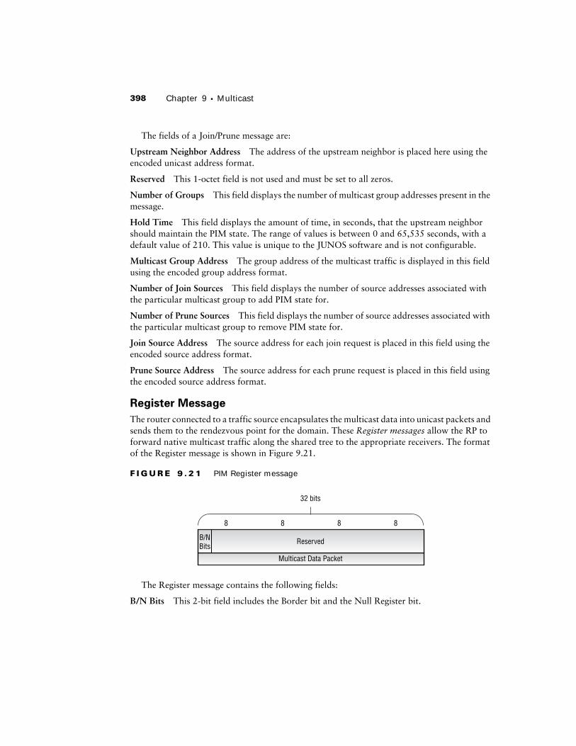
Register Message
The router connected to a traffic source encapsulates the multicast data into unicast packets and sends them to the rendezvous point for the domain. These Register messages allow the RP to forward native multicast traffic along the shared tree to the appropriate receivers. The format of the Register message is shown in Figure 9.21.
F I G U R E 9 . 2 1 PIM Register message
The Register message contains the following fields:
B/N Bits This 2-bit field includes the Border bit and the Null Register bit.
32 bits
88
Multicast Data Packet
Reserved
88
B/NBits
Multicast Protocols 399
Border bit When the router sending the Register message is directly connected to the source, it sets the Border bit to the value 0. Otherwise, the bit is set to 1, which means that the source is not directly connected.
Null Register bit The Null Register bit is normally set to the value 0. When the sending router wants to probe the RP, it sets the bit to 1. The probe process allows the router to check with the RP to see if it should actually send the multicast traffic in a Register message. This process continues until the multicast source stops generating its data stream and allows the RP to maintain knowledge of the active multicast source.
Multicast Data Packet The multicast packets from the source are placed in this field for trans-mission to the RP. A null register message does not populate this field.
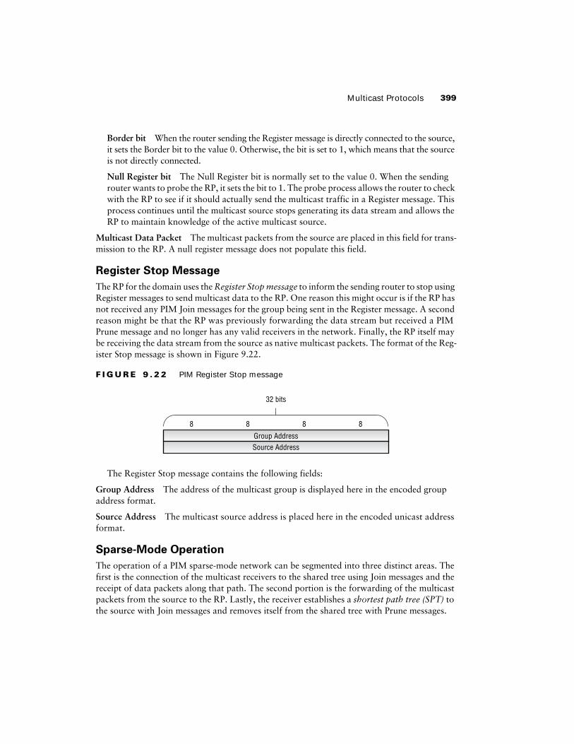
Register Stop Message
The RP for the domain uses the Register Stop message to inform the sending router to stop using Register messages to send multicast data to the RP. One reason this might occur is if the RP has not received any PIM Join messages for the group being sent in the Register message. A second reason might be that the RP was previously forwarding the data stream but received a PIM Prune message and no longer has any valid receivers in the network. Finally, the RP itself may be receiving the data stream from the source as native multicast packets. The format of the Reg-ister Stop message is shown in Figure 9.22.
F I G U R E 9 . 2 2 PIM Register Stop message
The Register Stop message contains the following fields:
Group Address The address of the multicast group is displayed here in the encoded group address format.
Source Address The multicast source address is placed here in the encoded unicast address format.
Sparse-Mode Operation
The operation of a PIM sparse-mode network can be segmented into three distinct areas. The first is the connection of the multicast receivers to the shared tree using Join messages and the receipt of data packets along that path. The second portion is the forwarding of the multicast packets from the source to the RP. Lastly, the receiver establishes a shortest path tree (SPT) to the source with Join messages and removes itself from the shared tree with Prune messages.
32 bits
88
Source AddressGroup Address
88
400 Chapter 9 � Multicast
Generally speaking, the establishment of the shared tree and the forwarding of packets to the RP can occur in any order. The RP might receive Register messages and have no Join state from receivers. Conversely, the RP might receive Join messages from a downstream neighbor, but have no multicast packets to send. Regardless of this fact, let’s cover the separate portions of the operation in the order we laid out earlier.
Establishing the Shared Tree
When an end station decides that it would like to receive multicast traffic, it generates an IGMP Report message for the group address it wishes to receive traffic for. The designated router for the segment (also the last-hop router on the forwarding path) generates a PIM Join message and for-wards it to the RP. Each router along the path to the RP establishes a (*,G) state for the group address. This state includes the address itself, the downstream interface to the receiver, and the upstream interface to the RP. When the RP receives the PIM Join from downstream, it also installs a (*,G) state. If a valid multicast source is known, the RP begins forwarding native multicast pack-ets to the receiver along the shared tree. At this point, each router along the path also installs an (S,G) state entry because an explicit source is now known. As the data stream reaches the last-hop router, it also installs an (S,G) state and forwards the packets to the receiver.
While multicast packets are flowing along the shared tree, all RPF checks are performed against the address of the RP, not the multicast source.
Forwarding Packets to the RP
When a multicast source has traffic to send, it begins to generate that traffic and forwards it to its local LAN. A PIM router on that network, the first-hop router in the forwarding path, encapsu-lates the traffic in a PIM Register message and sends it to the RP. If the RP has a current (*,G) state for the received group address, it de-encapsulates the traffic and forwards it along the shared tree. If no (*,G) state exists, the RP generates a Register Stop message and sends it to the first-hop router. This causes the first-hop router to stop sending the traffic to the RP and to start a 60-second timer. As the timer expires, the first-hop router generates a Register message that contains no multicast traffic, but has the Null Register bit set (often referred to as a Null Register message). The RP once again determines what state exists for the advertised group address and takes the appropriate action. If the first-hop router again receives a Register Stop, it starts its timer again.
This process of sending Null Register and Register Stop messages between the first-hop router and the RP continues until the source stops sending traffic.
Establishing the Shortest Path Tree
Once the last-hop router learns about a source for the data stream it is forwarding to the receiver, it connects itself to the shortest path tree for that (S,G). The last-hop router generates a PIM Join message with the (S,G) state defined and forwards it to an upstream router to the source. Each intermediate router forwards the Join message while also establishing an (S,G) state locally. When
Multicast Protocols 401
the first-hop router receives the Join message, it also establishes an (S,G) state and begins forward-ing native multicast packets along the newly created SPT.
When the last-hop router begins to receive the traffic stream from the SPT, it then removes itself from the shared tree. A PIM Prune message is generated and sent upstream along the shared tree towards the RP. The intermediate routers along the shared tree remove the (S,G) from their database and forward the Prune message to the RP. When the RP receives the mes-sage, it also removes its (S,G) state and stops forwarding the multicast traffic along the shared tree. If this leaves the RP with no receivers for the multicast group, it generates a Register Stop message and sends it to the first-hop router.
Rendezvous Point Options
We’ve discussed the function of the rendezvous point in a sparse-mode network many times thus far. In fact, it is a critical component of a multicast network. What we haven’t done is discuss how the routers in the network know what the RP address actually is. There are three ways for a sparse-mode network to learn the address of the RP: through a static configuration, through a dynamic process called Auto-RP, or through a PIM specification known as the bootstrap router. Let’s explore each of these options.
Static
As the name implies, a static RP configuration means that you manually configure the address of the RP on each router in your network. This approach carries with it similar advantages and disadvantages to using static routes as your Interior Gateway Protocol. The biggest advantage is that you know exactly which router will always be the RP. Additionally, there is no protocol overhead to be concerned about. Of course, the biggest disadvantage is the lack of dynamic fail-over. If the RP in your network fails, you need to reconfigure each router with the address of the new rendezvous point.
Auto-RP
Auto-RP is a proprietary dynamic advertisement mechanism developed by Cisco Systems that is supported in the JUNOS software. It is capable of supporting redundant candidate RP routers in the multicast domain. One router in the network, the mapping agent, performs a special func-tion. It selects the operational RP for the network and advertises this decision to the network. The PIM routers learn the RP address via this message.
Forwarding PIM Joins Upstream
We have assumed that no PIM state exists on any router during this discussion. This is not always the case, however. In the real world, it is entirely possible for some routers to have an existing (S,G) state for the requested multicast group address. When this happens, the inter-mediate router stops forwarding the Join upstream to the RP or first-hop router. Instead, it adds the neighbor to its list of downstream interfaces and begins to forward the multicast traffic to that neighbor.
402 Chapter 9 � Multicast
The operation of Auto-RP is fairly straightforward. Each router that you configure to be a ren-dezvous point begins generating Cisco-RP-Announce messages addressed to the 224.0.1.39 /32 group address. These Announce messages are transmitted through the network in a dense-mode fashion, ensuring that each router receives a copy. The mapping agent for the network listens for the various Announce messages and makes a decision as to which router is the RP. By default, the candidate RP with the highest IP address is chosen as the RP for the network. The mapping agent then advertises this decision to the network in a Cisco-RP-Discovery message addressed to the 224.0.1.40 /32 group address. Like the Announce message, the Discovery message is propagated in a dense-mode fashion throughout the network.
The dynamic fail-over capability of Auto-RP arises from the mapping functionality. If the selected RP stops operating, its Announce messages no longer arrive at the mapping agent. The mapping router then selects a new RP for the network and advertises that selection to the net-work in a Discovery message.
Bootstrap Router
The original specification of PIM version 2 defined a dynamic RP announcement mechanism called the bootstrap router (BSR). The end goal of the bootstrap router process is very similar to the outcome of the Auto-RP system. Multiple candidate RP routers advertise their capabili-ties to the network. A single router, the bootstrap router, collects the advertisements and adver-tises the RP information to the network.
The bootstrap router process is now defined in a separate Internet Draft. Please see www.ietf.org/ID.html for the latest version of this specification.
A multicast network can support only a single BSR at any point in time, but multiple candidate routers may be operational simultaneously. Each candidate BSR advertises a priority value to the network using PIM Bootstrap messages addressed to the 224.0.0.13 /32 group address (all PIM routers). The candidate BSR with the highest priority value is elected as the BSR for the domain.
Once elected, the BSR collects Candidate-RP-Advertisements from any router configured as a rendezvous point. The Advertisement messages are Unicast directly to the BSR by the can-didate RP routers. Unlike the Auto-RP mapping agent, which selects a single RP, the BSR advertises all valid RP routers in a message called the RP-Set. This message contains the address of the RP, the possible group addresses that RP supports, and a priority value. The BSR advertises the RP-Set to the network as a PIM message, where all of the multicast routers receive it. Each individual router then makes its own decision about which RP should be used for which multicast group address. This process allows multiple RP routers to operate simul-taneously and load-balances the protocol traffic across those routers.
While the description of the RP-Set may sound a little chaotic, there is actually a defined pro-cess for selecting the RP for a group address. The tie-breaking steps are:
1. Choose the candidate RP advertising the most specific range of addresses. For example, say a router receives an IGMP Report message for the 224.100.1.1 /32 group address. The two candidate RP routers in the RP-Set have advertised group ranges of 224.0.0.0 /4 and 224.100.0.0 /16, respectively. The PIM router chooses the RP advertising the 224.100.0.0 /16 range because it is more specific.
JUNOS software Commands 403
2. Choose the candidate RP with the highest advertised priority in the RP-Set.
3. Choose the candidate RP that is returned by the bootstrap hash algorithm. Each PIM router using the bootstrap router process has the capability to operate a hash mechanism to choose the RP. Information such as the candidate RP address and the group address is combined with a defined mask value and run through the algorithm.
4. Choose the candidate RP with the highest IP address from the remaining list of candidates.
It is possible to have multiple RP election mechanisms operating simulta-neously. In this instance, the JUNOS software prefers the RP found using bootstrap routing over Auto-RP, which is preferred to a static configuration.
JUNOS software CommandsWe’ve seen how to forward multicast traffic in a network, and we’ve covered the operational theory of IGMP and PIM. Let’s now examine the implementation of the multicast protocols within the JUNOS software, using Figure 9.23 as a reference for this section. We begin with the configuration of IGMP. Then we discuss the establishment of PIM on the router and examine the various options for configuring the rendezvous point. Finally, we explore some useful com-mands for verifying and troubleshooting your multicast network.
F I G U R E 9 . 2 3 Multicast network
Chardonnay192.168.40.1
Merlot192.168.56.1
Shiraz192.168.36.1
Muscat192.168.32.1
Riesling192.168.48.1
Cabernet192.168.52.1
Source1.1.1.1
Receiver10.200.200.16
10.2
22.3
.2
10.2
22.3
.1
10.2
22.6
0.1
10.2
22.6
0.2
10.2
22.4
4.2
10.2
22.4
4.1
10.2
22.6
.1
10.2
22.6
.2
10.2
22.4
5.1
10.2
22.4
5.2
10.2
22.6
1.1
10.2
22.6
1.2
10.200.200.11.1.1.2
404 Chapter 9 � Multicast
IGMP Configuration
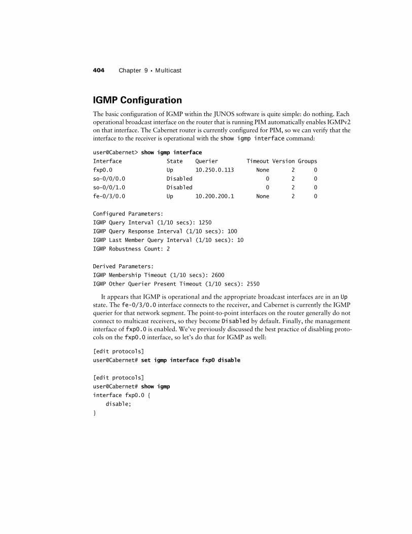
The basic configuration of IGMP within the JUNOS software is quite simple: do nothing. Each operational broadcast interface on the router that is running PIM automatically enables IGMPv2 on that interface. The Cabernet router is currently configured for PIM, so we can verify that the interface to the receiver is operational with the show igmp interface command:
user@Cabernet> show igmp interface
Interface State Querier Timeout Version Groups
fxp0.0 Up 10.250.0.113 None 2 0
so-0/0/0.0 Disabled 0 2 0
so-0/0/1.0 Disabled 0 2 0
fe-0/3/0.0 Up 10.200.200.1 None 2 0
Configured Parameters:
IGMP Query Interval (1/10 secs): 1250
IGMP Query Response Interval (1/10 secs): 100
IGMP Last Member Query Interval (1/10 secs): 10
IGMP Robustness Count: 2
Derived Parameters:
IGMP Membership Timeout (1/10 secs): 2600
IGMP Other Querier Present Timeout (1/10 secs): 2550
It appears that IGMP is operational and the appropriate broadcast interfaces are in an Up state. The fe-0/3/0.0 interface connects to the receiver, and Cabernet is currently the IGMP querier for that network segment. The point-to-point interfaces on the router generally do not connect to multicast receivers, so they become Disabled by default. Finally, the management interface of fxp0.0 is enabled. We’ve previously discussed the best practice of disabling proto-cols on the fxp0.0 interface, so let’s do that for IGMP as well:
[edit protocols]
user@Cabernet# set igmp interface fxp0 disable
[edit protocols]
user@Cabernet# show igmp
interface fxp0.0 {
disable;
}
JUNOS software Commands 405
We verify that the fxp0.0 interface is no longer operating IGMP:
user@Cabernet> show igmp interface
Interface State Querier Timeout Version Groups
fxp0.0 Disabled 0 2 0
so-0/0/0.0 Disabled 0 2 0
so-0/0/1.0 Disabled 0 2 0
fe-0/3/0.0 Up 10.200.200.1 None 2 0
Configured Parameters:
IGMP Query Interval (1/10 secs): 1250
IGMP Query Response Interval (1/10 secs): 100
IGMP Last Member Query Interval (1/10 secs): 10
IGMP Robustness Count: 2
Derived Parameters:
IGMP Membership Timeout (1/10 secs): 2600
IGMP Other Querier Present Timeout (1/10 secs): 2550
If you are required to use a different version of IGMP, individual interfaces can be config-ured with the version command. Suppose the receiver connected to the Cabernet router is now capable of using IGMPv3 and would like to utilize some of its features. We alter the con-figuration of interface fe-0/3/0.0 like so:
[edit protocols]
user@Cabernet# set igmp interface fe-0/3/0 version 3
[edit protocols]
user@Cabernet# show igmp
interface fxp0.0 {
disable;
}
interface fe-0/3/0.0 {
version 3;
}
[edit protocols]
user@Cabernet# run show igmp interface
Interface State Querier Timeout Version Groups
fxp0.0 Disabled 0 2 0
so-0/0/0.0 Disabled 0 2 0
so-0/0/1.0 Disabled 0 2 0
fe-0/3/0.0 Up 10.200.200.1 None 3 0
406 Chapter 9 � Multicast
Configured Parameters:
IGMP Query Interval (1/10 secs): 1250
IGMP Query Response Interval (1/10 secs): 100
IGMP Last Member Query Interval (1/10 secs): 10
IGMP Robustness Count: 2
Derived Parameters:
IGMP Membership Timeout (1/10 secs): 2600
IGMP Other Querier Present Timeout (1/10 secs): 2550
PIM Configuration
The most common configuration for PIM on a Juniper Networks router is simply enabling the interfaces themselves within the [edit protocols pim] hierarchy. Each interface is config-ured to operate in dense, sparse-dense, or sparse mode. Let’s briefly examine each of these con-figuration options and then explore the methods for configuring the PIM rendezvous point.
Dense Mode
Dense-mode PIM is the default operation mode in the JUNOS software for all interfaces. As such, the configuration is very straightforward. Referring back to Figure 9.23, let’s use the key-word all to enable dense-mode PIM on the Chardonnay router:
[edit protocols]
user@Chardonnay# set pim interface all
user@Chardonnay# set pim interface fxp0 disable
[edit protocols]
user@Chardonnay# show pim
interface all;
interface fxp0.0 {
disable;
}
We verify our configuration with the show pim interfaces command:
user@Chardonnay> show pim interfaces
Instance: PIM.master
Name Stat Mode V State Priority DR address Neighbors
at-0/1/1.0 Up Dense 2 P2P 0
lo0.0 Up Dense 2 DR 1 192.168.40.1 0
so-0/0/0.0 Up Dense 2 P2P 0
JUNOS software Commands 407
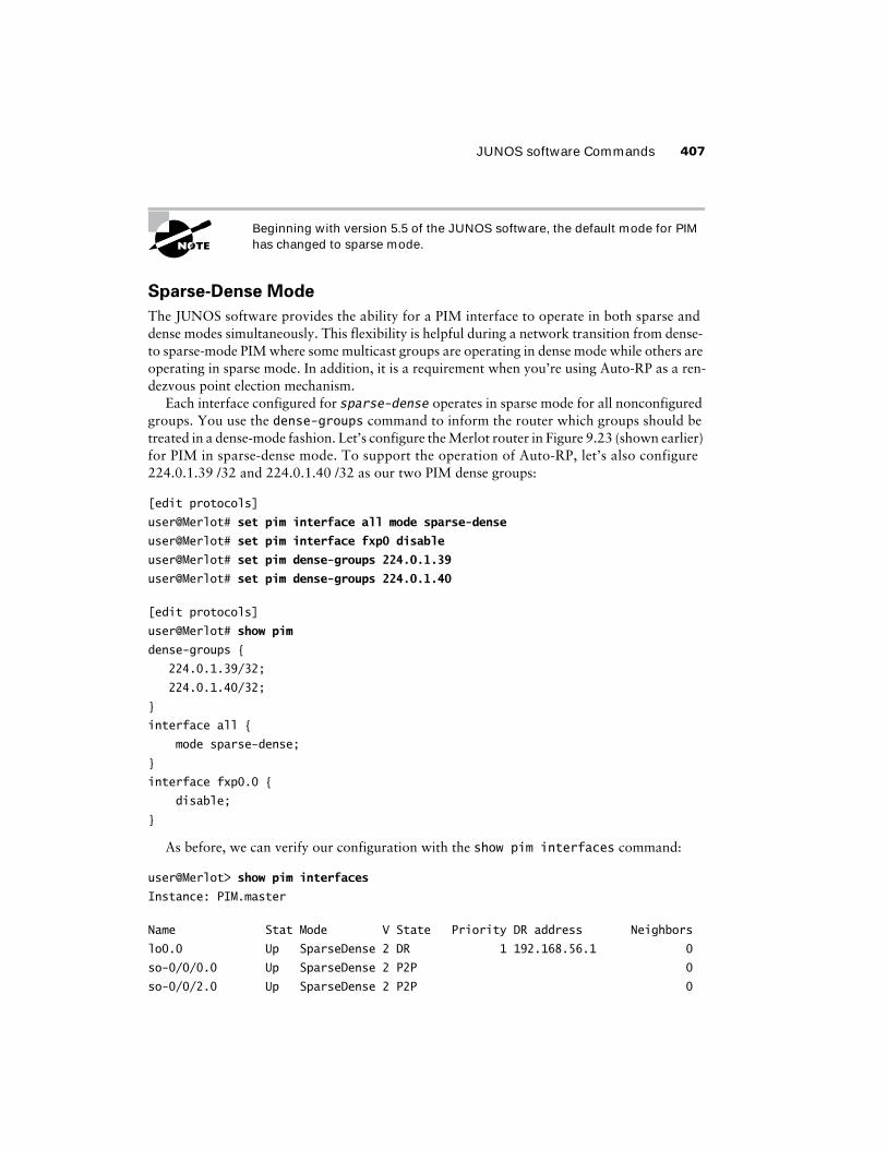
Beginning with version 5.5 of the JUNOS software, the default mode for PIM has changed to sparse mode.
Sparse-Dense Mode
The JUNOS software provides the ability for a PIM interface to operate in both sparse and dense modes simultaneously. This flexibility is helpful during a network transition from dense- to sparse-mode PIM where some multicast groups are operating in dense mode while others are operating in sparse mode. In addition, it is a requirement when you’re using Auto-RP as a ren-dezvous point election mechanism.
Each interface configured for sparse-dense operates in sparse mode for all nonconfigured groups. You use the dense-groups command to inform the router which groups should be treated in a dense-mode fashion. Let’s configure the Merlot router in Figure 9.23 (shown earlier) for PIM in sparse-dense mode. To support the operation of Auto-RP, let’s also configure 224.0.1.39 /32 and 224.0.1.40 /32 as our two PIM dense groups:
[edit protocols]
user@Merlot# set pim interface all mode sparse-dense
user@Merlot# set pim interface fxp0 disable
user@Merlot# set pim dense-groups 224.0.1.39
user@Merlot# set pim dense-groups 224.0.1.40
[edit protocols]
user@Merlot# show pim
dense-groups {
224.0.1.39/32;
224.0.1.40/32;
}
interface all {
mode sparse-dense;
}
interface fxp0.0 {
disable;
}
As before, we can verify our configuration with the show pim interfaces command:
user@Merlot> show pim interfaces
Instance: PIM.master
Name Stat Mode V State Priority DR address Neighbors
lo0.0 Up SparseDense 2 DR 1 192.168.56.1 0
so-0/0/0.0 Up SparseDense 2 P2P 0
so-0/0/2.0 Up SparseDense 2 P2P 0
408 Chapter 9 � Multicast
Sparse Mode
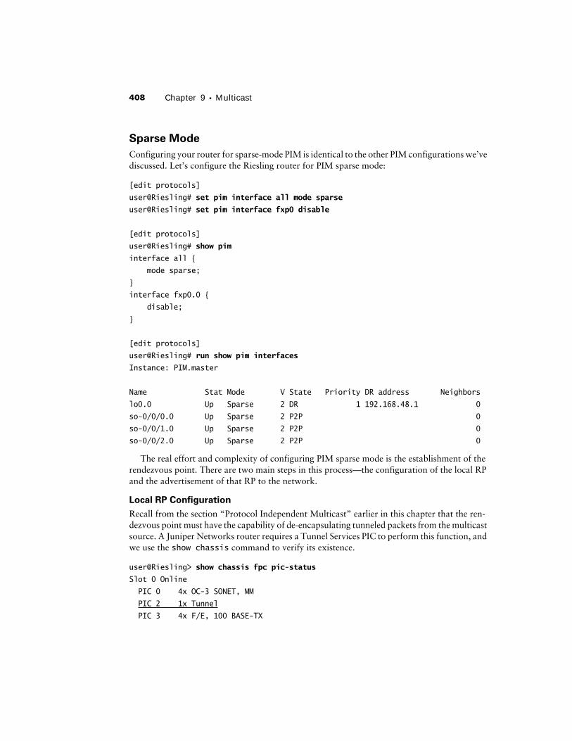
Configuring your router for sparse-mode PIM is identical to the other PIM configurations we’ve discussed. Let’s configure the Riesling router for PIM sparse mode:
[edit protocols]
user@Riesling# set pim interface all mode sparse
user@Riesling# set pim interface fxp0 disable
[edit protocols]
user@Riesling# show pim
interface all {
mode sparse;
}
interface fxp0.0 {
disable;
}
[edit protocols]
user@Riesling# run show pim interfaces
Instance: PIM.master
Name Stat Mode V State Priority DR address Neighbors
lo0.0 Up Sparse 2 DR 1 192.168.48.1 0
so-0/0/0.0 Up Sparse 2 P2P 0
so-0/0/1.0 Up Sparse 2 P2P 0
so-0/0/2.0 Up Sparse 2 P2P 0
The real effort and complexity of configuring PIM sparse mode is the establishment of the rendezvous point. There are two main steps in this process—the configuration of the local RP and the advertisement of that RP to the network.
Local RP Configuration
Recall from the section “Protocol Independent Multicast” earlier in this chapter that the ren-dezvous point must have the capability of de-encapsulating tunneled packets from the multicast source. A Juniper Networks router requires a Tunnel Services PIC to perform this function, and we use the show chassis command to verify its existence.
user@Riesling> show chassis fpc pic-status
Slot 0 Online
PIC 0 4x OC-3 SONET, MM
PIC 2 1x Tunnel
PIC 3 4x F/E, 100 BASE-TX
JUNOS software Commands 409
The Riesling router has a Tunnel Services PIC, so we make it the rendezvous point for the domain. Within the [edit protocols pim rp] configuration hierarchy, we inform Riesling that it should be the rendezvous point by using the loopback address in conjunction with the local command:
[edit protocols]
user@Riesling# set pim rp local address 192.168.48.1
[edit protocols]
user@Riesling# show pim
rp {
local {
address 192.168.48.1;
}
}
interface all {
mode sparse;
}
interface fxp0.0 {
disable;
}
Troubleshooting a Local RP Setup
Let’s assume that you’ve configured your new RP router with the pim rp local address address command and committed your configuration. Using one of the RP election mechanisms (static, Auto-RP, or BSR), each PIM router in your domain has learned that the local router is the RP. A multicast source begins to send traffic and several interested receivers are online. Unfortunately, the traffic is not getting from the source to the clients. There are several problems that might be causing this to occur.
One problem might be that the first-hop router is not receiving the multicast traffic from the directly connected source. We check the interface statistics on that router and see that it is receiv-ing large amounts of traffic on the appropriate interface. The first-hop router knows which router is the RP for the domain, so we can assume that it is forwarding the traffic in Register messages to the local RP router.
410 Chapter 9 � Multicast
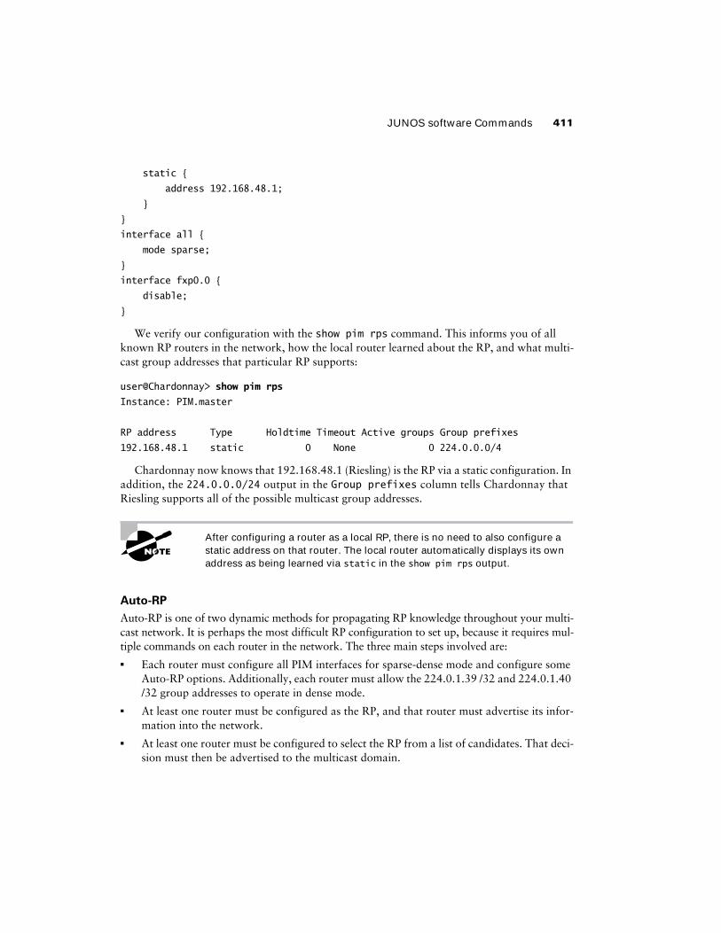
Static RP
Once the rendezvous point for the domain is configured, each router in the network needs to learn which router is the RP. Perhaps the simplest way to accomplish this goal is to explicitly configure every router with the address of the RP. Unfortunately, the static RP configuration carries with it the disadvantages of static routes. You have no dynamic fail-over available to you if the RP were to stop operating, and the configuration is active until you manually change it.
We’ve already made Riesling the RP for the domain. We now configure each router with the static command in the [edit protocols pim rp] configuration hierarchy. We supply the address of the RP (Riesling’s loopback address) to enable the routers to forward PIM Join and Prune messages as needed. Each of the routers in Figure 9.23 (shown earlier) contains an iden-tical configuration, so we examine just the Chardonnay router here:
[edit protocols]
user@Chardonnay# set pim rp static address 192.168.48.1
[edit protocols]
user@Riesling# show pim
rp {
A second problem might be that the (*,G) PIM state is not established from the last-hop routers toward the local RP. After examining the state on each router, we find that the correct (*,G) state is installed. Also, the correct interfaces (according to the RPF tables) have been used to send the Join messages to the RP.
The remaining issues reside at the local RP itself. The Join messages might not be reaching the RP from the last-hop routers, or the Register messages from the first-hop router are not arriv-ing. The obvious place to start checking is the PIM Join state and we find the appropriate (*,G) installed for the group address. This leaves us with the communication between the RP and the first-hop router.
Recall that native multicast data is encapsulated into a Register message by the first-hop router and is sent to the RP as a unicast packet. The RP must then de-encapsulate that Register mes-sage before forwarding any multicast traffic along the shared tree toward the receivers. We use the show chassis fpc pic-status command and find that our local RP router doesn’t have a Tunnel PIC installed. Without it, the RP can’t de-encapsulate the Register message.
The JUNOS software automatically creates encapsulation and de-encapsulation interfaces for this PIM function when a Tunnel PIC is installed. However, the lack of a Tunnel PIC doesn’t gen-erate an error message. While you may find this odd, remember that the router always allows you to enter configuration information for transient interfaces that are not physically present in the router. Once we insert our Tunnel PIC into the local RP router, the de-encapsulation inter-face (pd-1/0/1.32768, for example) is created, the Register messages are received, and the RP begins forwarding the multicast traffic down the shared tree toward the receivers.
JUNOS software Commands 411
static {
address 192.168.48.1;
}
}
interface all {
mode sparse;
}
interface fxp0.0 {
disable;
}
We verify our configuration with the show pim rps command. This informs you of all known RP routers in the network, how the local router learned about the RP, and what multi-cast group addresses that particular RP supports:
user@Chardonnay> show pim rps
Instance: PIM.master
RP address Type Holdtime Timeout Active groups Group prefixes
192.168.48.1 static 0 None 0 224.0.0.0/4
Chardonnay now knows that 192.168.48.1 (Riesling) is the RP via a static configuration. In addition, the 224.0.0.0/24 output in the Group prefixes column tells Chardonnay that Riesling supports all of the possible multicast group addresses.
After configuring a router as a local RP, there is no need to also configure a static address on that router. The local router automatically displays its own address as being learned via static in the show pim rps output.
Auto-RP
Auto-RP is one of two dynamic methods for propagating RP knowledge throughout your multi-cast network. It is perhaps the most difficult RP configuration to set up, because it requires mul-tiple commands on each router in the network. The three main steps involved are:� Each router must configure all PIM interfaces for sparse-dense mode and configure some
Auto-RP options. Additionally, each router must allow the 224.0.1.39 /32 and 224.0.1.40 /32 group addresses to operate in dense mode.
� At least one router must be configured as the RP, and that router must advertise its infor-mation into the network.
� At least one router must be configured to select the RP from a list of candidates. That deci-sion must then be advertised to the multicast domain.
412 Chapter 9 � Multicast
Within the [edit protocols pim rp] configuration hierarchy, you use the auto-rp com-mand to tell the router how to participate in the Auto-RP network. Three options are available for the command:
discovery The discovery option is the most basic Auto-RP configuration. It allows the router to listen for announcements from the mapping agent in the network and use any received RP information.
announce The announce option also allows the local router to listen for mapping announce-ments. In addition, the local router informs the network that it is configured to be a rendezvous point for the domain.
mapping The mapping option allows the router to perform all Auto-RP functions. It can listen for announcements from other mapping agents in the network, it can advertise a local RP con-figuration to the domain, and it can perform the Auto-RP mapping function.
In the network shown earlier in Figure 9.23, we configure Auto-RP for the domain. Riesling is the RP for the network, and Muscat is the Auto-RP mapping agent. All of the other routers should propagate the Auto-RP messages and listen for the mapping messages from Muscat. The Shiraz, Chardonnay, Merlot, and Cabernet routers all share a similar configuration, so we examine just the Merlot router as an example:
[edit protocols]
user@Merlot# set pim interface all mode sparse-dense
user@Merlot# set pim interface fxp0 disable
user@Merlot# set pim dense-groups 224.0.1.39
user@Merlot# set pim dense-groups 224.0.1.40
user@Merlot# set pim rp auto-rp discovery
[edit protocols]
user@Merlot# show pim
dense-groups {
224.0.1.39/32;
224.0.1.40/32;
}
rp {
auto-rp discovery;
}
interface all {
mode sparse-dense;
}
interface fxp0.0 {
disable;
}
JUNOS software Commands 413
The Riesling router is already configured as a local RP, so we add only the Auto-RP config-uration steps to it:
[edit protocols]
user@Riesling# set pim interface all mode sparse-dense
user@Riesling# set pim dense-groups 224.0.1.39
user@Riesling# set pim dense-groups 224.0.1.40
user@Riesling# set pim rp auto-rp announce
[edit protocols]
user@Riesling# show pim
dense-groups {
224.0.1.39/32;
224.0.1.40/32;
}
rp {
local {
192.168.48.1;
}
auto-rp announce;
}
interface all {
mode sparse-dense;
}
interface fxp0.0 {
disable;
}
Finally, we configure the Muscat router as the Auto-RP mapping agent for the domain:
[edit protocols]
user@Muscat# set pim interface all mode sparse-dense
user@Muscat# set pim interface fxp0 disable
user@Muscat# set pim dense-groups 224.0.1.39
user@Muscat# set pim dense-groups 224.0.1.40
user@Muscat# set pim rp auto-rp mapping
[edit protocols]
user@Muscat# show pim
dense-groups {
414 Chapter 9 � Multicast
224.0.1.39/32;
224.0.1.40/32;
}
rp {
auto-rp mapping;
}
interface all {
mode sparse-dense;
}
interface fxp0.0 {
disable;
}
We verify the operation of the network with the show pim rps command and the optional detail variable. A check of the Cabernet router shows that an RP has been learned through auto-rp:
user@Cabernet> show pim rps
Instance: PIM.master
RP address Type Holdtime Timeout Active groups Group prefixes
192.168.48.1 auto-rp 150 131 2 224.0.0.0/4
Riesling is the RP for the multicast domain and it is supporting all possible multicast group addresses. A non-zero value appears in the Active groups column, so it appears that some multicast traffic is actually flowing in the network. We can determine which group addresses are using this RP, from Cabernet’s perspective, by adding the detail option:
user@Cabernet> show pim rps detail
Instance: PIM.master
RP: 192.168.48.1
Learned from 192.168.32.1 via: auto-rp
Time Active: 00:04:05
Holdtime: 150 with 128 remaining
Group Ranges:
224.0.0.0/4
Active groups using RP:
224.7.7.7
224.8.8.8
total 2 groups active
JUNOS software Commands 415
We configured Muscat (192.168.32.1) as the Auto-RP mapping agent for the domain. The out-put from Cabernet tells us that the address of the RP was learned from Muscat using auto-rp. We see something interesting when we use the show pim rps command on Riesling:
user@Riesling> show pim rps
Instance: PIM.master
RP address Type Holdtime Timeout Active groups Group prefixes
192.168.48.1 auto-rp 150 136 2 224.0.0.0/4
192.168.48.1 static 0 None 2 224.0.0.0/4
Since Riesling was configured with the announce option, it also listened for the mapping messages from Muscat. It received those messages and installed 192.168.48.1 as an RP address. It also has that same address listed as being learned from a static configuration. We didn’t make a mistake earlier; this is a normal output for an RP router. The local configuration appears as a static-learned RP in the output of this command.
Bootstrap Router
The bootstrap router is the second method for dynamically propagating RP knowledge in your network. The configuration of a bootstrap router relies on a sparse-mode PIM network as con-figured in the “Sparse Mode” section earlier in this chapter. This provides the basis for sending PIM bootstrap messages between the routers in the network. The bootstrap election is depen-dent on the highest configured router priority in the multicast domain. In the case of a priority tie, the router with the highest router ID is elected the BSR.
For our sample network, Riesling is again the RP. Both the Chardonnay and Riesling routers are configured with a non-zero priority value. All other routers in the network do not configure a priority and inherit the default value of 0, making them ineligible to become the bootstrap router. The Riesling router already has its local RP and basic PIM configuration in place. We now assign a priority value of 50:
[edit protocols]
user@Riesling# set pim rp bootstrap-priority 50
[edit protocols]
user@Riesling# show pim
rp {
local {
192.168.48.1;
}
bootstrap-priority 50;
}
interface all {
416 Chapter 9 � Multicast
mode sparse;
}
interface fxp0.0 {
disable;
}
The Chardonnay router receives a priority value of 100:
[edit protocols]
user@Chardonnay# set pim rp bootstrap-priority 100
[edit protocols]
user@Chardonnay# show pim
rp {
bootstrap-priority 100;
}
interface all {
mode sparse;
}
interface fxp0.0 {
disable;
}
We verify the operation of the network with the show pim rps command. We check the Muscat router and see that an RP has been learned through bootstrap:
user@Muscat> show pim rps
Instance: PIM.master
RP address Type Holdtime Timeout Active groups Group prefixes
192.168.48.1 bootstrap 150 131 2 224.0.0.0/4
After configuring the routers with their bootstrap priorities, we can check the election pro-cess with the show pim bootstrap command. The output contains information about both the network bootstrap router as well as the local router’s configuration. We first examine the Mus-cat router:
user@Muscat> show pim bootstrap
Instance: PIM.master
BSR Pri Local address Pri State Timeout
192.168.40.1 100 192.168.32.1 0 InEligible 132
JUNOS software Commands 417
Both the BSR and the first Pri columns display information about the elected bootstrap router—Chardonnay (192.168.40.1) has a priority value of 100. The remaining columns rep-resent Muscat’s local configuration. Its priority value of 0 makes it InEligible to become the bootstrap router. We next view the output of the Riesling router.
user@Riesling> show pim bootstrap
Instance: PIM.master
BSR Pri Local address Pri State Timeout
192.168.40.1 100 192.168.48.1 50 Candidate 75
Again, we see that Chardonnay is the bootstrap router with its priority of 100. The local bootstrap configuration shows that Riesling has a bootstrap priority of 50 and is currently a Candidate. Finally, the output for Chardonnay shows that it is both the current bootstrap router and its local state is Elected:
user@Chardonnay> show pim bootstrap
Instance: PIM.master
BSR Pri Local address Pri State Timeout
192.168.40.1 100 192.168.40.1 100 Elected 95
show pim neighbors
To view the neighboring routers in the network, we use the show pim neighbors command. Each active PIM neighbor is displayed with its physical IP address. In addition, the output dis-plays the local router’s interfaces with a timeout value of 65,535:
user@Cabernet> show pim neighbors
Instance: PIM.master
Interface DR priority Neighbor addr V Mode Holdtime Timeout
lo0.0 1 192.168.52.1 2 SparseDense 65535 0
so-0/0/0.0 1 10.222.60.1 2 SparseDense 65535 0
so-0/0/0.0 1 10.222.60.2 2 Unknown 105 81
fe-0/3/0.0 1 10.200.200.1 2 SparseDense 65535 0
The Mode of the 10.222.60.2 neighbor is currently Unknown because this infor-mation is not transmitted in a PIM message into the network.
418 Chapter 9 � Multicast
show pim join extensive
The show pim join extensive command provides a wealth of information about the current state of your multicast network. In addition to the multicast group address and the multicast source, you gain visibility of the interfaces used to forward the data streams:
Each multicast group address is displayed with its source, if known. The 0.0.0.0 notation in our output informs us that the source address is not known to Cabernet. This coincides with the fact that the Upstream State: is currently listed as Join to RP. This tells you that the local router has forwarded PIM Join messages to the RP and has joined the shared tree (rptree). When the data traffic from the RP begins to flow, Cabernet expects to receive it on so-0/0/0.0, its upstream interface. The traffic is then forwarded out the downstream interface, fe-0/3/0.0, to its neighbor at 10.200.200.1.
show pim source
One method for viewing the active multicast sources in the network is by using the show pim source command. The address of each source is listed in addition to the interface the local router expects to receive traffic on:
The Shiraz router is connected to the multicast source of 1.1.1.1 /32, which is listed as Direct. Additionally, the address of the current RP, 192.168.48.1 /32, is listed because packets might be received when Shiraz connects to a shared tree for a particular group address.
show multicast rpf
To view the reverse path forwarding table used by the router during multicast forwarding, you use the show multicast rpf command. The output displays the IP subnet, the protocol install-ing the route, and the interface the multicast traffic should be received on. We can see the default usage of the inet.0 routing table.
user@Cabernet> show multicast rpf
Multicast RPF table: inet.0
Source prefix Protocol RPF interface RPF neighbor
1.1.1.0/24 OSPF so-0/0/0.0 (null)
10.200.200.0/24 Direct fe-0/3/0.0
10.200.200.1/32 Local
10.222.3.0/24 OSPF so-0/0/0.0 (null)
10.222.5.2/32 Local
10.222.6.0/24 OSPF so-0/0/0.0 (null)
10.222.44.0/24 OSPF so-0/0/0.0 (null)
10.222.45.0/24 OSPF so-0/0/0.0 (null)
10.222.60.0/24 Direct so-0/0/0.0
10.222.60.1/32 Local
10.222.61.0/24 OSPF so-0/0/0.0 (null)
10.250.0.0/16 Direct fxp0.0
10.250.0.119/32 Local
192.168.32.1/32 OSPF so-0/0/0.0 (null)
192.168.36.1/32 OSPF so-0/0/0.0 (null)
192.168.40.1/32 OSPF so-0/0/0.0 (null)
192.168.48.1/32 OSPF so-0/0/0.0 (null)
192.168.52.1/32 Direct lo0.0
192.168.56.1/32 OSPF so-0/0/0.0 (null)
200.200.200.1/32 OSPF so-0/0/0.0 (null)
224.0.0.2/32 PIM
224.0.0.5/32 OSPF
224.0.0.13/32 PIM
420 Chapter 9 � Multicast
show multicast route
The show multicast route command is one of two commands you use to verify known multicast group addresses and their sources. The output displays the group, its source, and information about incoming/outgoing interfaces on the router:
user@Cabernet> show multicast route
Group Source prefix Act Pru InIf NHid Session Name
224.7.7.7 1.1.1.1 /32 A F 4 56
224.8.8.8 1.1.1.1 /32 A F 4 56
show route table inet.1
The show route table inet.1 command is the other command you use to verify multicast group addresses and their sources known to your router. Like other routing table output, the installing protocol, a route preference, and the route itself are displayed:
Many multicast show commands provide insight into the operation of your domain. However, they often only prove that the PIM or IGMP protocols are operating correctly. To truly view the amount of multicast traffic flowing in your network, use the show multicast usage command. The output provides information on the number of packets and bytes seen for each multicast group address known to the router:
user@Cabernet> show multicast usage
Group Sources Packets Bytes
224.7.7.7 1 70 19880
224.8.8.8 1 68 19312
Exam Essentials 421
SummaryIn this chapter, we explored the operation of a multicast routing network. This included a high-level view of why multicast forwarding is more efficient to reach multiple hosts from a single source of traffic. We also discussed the basic components of a multicast network, which include identifying multicast group addresses and translating those addresses into an Ethernet MAC address.
We examined the forwarding functions of a dense-mode network, with its flood and prune process, as well as a sparse-mode network and the rendezvous point. We saw how a multicast receiver connects to and leaves a multicast group using IGMP. We then discussed the PIM spec-ification, the various message types, the interaction of multicast routers, and the basic operation of a sparse-mode network. Following that was a look at the three methods for choosing a ren-dezvous point in the network—static, Auto-RP, and bootstrap router.
We finished our multicast discussion by examining configuration examples from Juniper Networks routers operating in dense and sparse modes. In addition, we detailed some JUNOS software commands used to troubleshoot and verify the operation of a multicast network.
Exam EssentialsBe able to describe the characteristics of a dense-mode multicast network. A dense-mode multicast network floods and prunes data traffic every three minutes. Each router in the net-work must explicitly prune itself from the forwarding tree if it doesn’t wish to receive traffic. In addition, a dense-mode network assumes that a large number of interested receivers exist for each multicast group address.
Be able to describe the characteristics of a sparse-mode multicast network. A sparse-mode multicast network utilizes the services of a rendezvous point. This connection router receives traf-fic from a source and requests from receivers, and places them together. A sparse-mode network assumes that a small number of interested receivers exist for each multicast group address. This requires each multicast router to explicitly add itself to the forwarding tree to receive traffic.
Be able to define the function of the Reverse Path Forwarding check. Each multicast router performs a Reverse Path Forwarding (RPF) check for each multicast packet it receives. The source of the data stream is examined and checked against a table to determine whether the receiving interface is the best path back to the source. If the check returns positively, a forwarding loop is not forming and the router can forward the packet downstream.
Be able to identify the basic function of IGMP. IGMPv1 defines the Query and Report message types. This allows a host to join a multicast group and provides the router with a method to verify the continued existence of interested receivers. Hosts leave the group address silently, leading to potentially long periods of time before traffic stops flowing onto the seg-ment. IGMPv2 addresses this problem by defining Group-Specific Query and Leave messages. Hosts can then explicitly inform the router to stop forwarding traffic.
422 Chapter 9 � Multicast
Be able to describe the operation of a PIM sparse-mode network. A sparse-mode PIM net-work operates in three main phases. First, the last-hop router joins the shared tree and receives multicast packets from the RP. Next, the first-hop router forwards multicast packets over a tun-nel to the RP using Register messages. Finally, the last-hop router joins the shortest path tree rooted at the first-hop router and prunes itself off the shared tree.
Be able to identify the three rendezvous point advertisement mechanisms. The three meth-ods used to propagate RP information to the network are static configuration, Auto-RP, and the bootstrap router mechanism.
Key TermsBefore you take the exam, be certain you are familiar with the following terms:
Auto-RP Protocol Independent Multicast (PIM)
bootstrap router (BSR) Prune message
Candidate-RP-Advertisements querier router
Cisco-RP-Announce Register message
Cisco-RP-Discovery Register Stop message
dense mode rendezvous point (RP)
designated router rendezvous point tree (RPT)
flood and prune reverse path forwarding (RPF)
group address RP-Set
Host Membership Query shared tree
Host Membership Report shortest path tree (SPT)
Internet Group Management Protocol (IGMP) source-based tree
Join message source-specific multicasting (SSM)
mapping agent sparse mode
Null Register message static RP
Review Questions 423
Review Questions1. Which term accurately describes the operation of a dense-mode network?
A. Join and graft
B. Graft and join
C. Flood and prune
D. Prune and flood
2. A dense-mode forwarding tree is built from the source to each of the receivers. What is the name of this tree?
A. Shared tree
B. Source-based tree
C. Wildcard tree
D. Flooding tree
3. How often does a dense-mode flood occur?
A. Every 30 seconds
B. Every 1 minute
C. Every 3 minutes
D. Every 5 minutes
4. When a multicast host is receiving packets from the rendezvous point, what type of tree is it joined to?
A. Shared tree
B. Source-based tree
C. Wildcard tree
D. Flooding tree
5. What does RPF stand for in a multicast network?
A. Reverse protocol forwarding
B. Reverse protocol flooding
C. Reverse path forwarding
D. Reverse path flooding
424 Chapter 9 � Multicast
6. Which multicast group address range is reserved for source-specific multicast (SSM)?
A. 224.0.0.0 /8
B. 232.0.0.0 /8
C. 233.0.0.0 /8
D. 239.0.0.0 /8
7. When a multicast group address is placed in an Ethernet frame, how many bits of the address are used?
A. 21 bits
B. 23 bits
C. 26 bits
D. 28 bits
8. What is the OUI assigned to an Ethernet multicast frame?
A. 0x00:00:5E
B. 0x01:00:5E
C. 0x00:11:5E
D. 0x01:11:5E
9. Which version of IGMP provides support for source-specific multicast?
A. IGMP
B. IGMPv2
C. IGMPv3
D. IGMPv4
10. Which PIM message type does a router send to the RP to notify it about a multicast source?
A. Join
B. Prune
C. Graft
D. Register
11. Which PIM message type does a router send to the RP when it receives an IGMP message from a receiver requesting traffic?
A. Join
B. Prune
C. Graft
D. Register
Review Questions 425
12. Which PIM message type does a router send upstream to request that a neighbor stop sending multicast traffic?
A. Join
B. Prune
C. Graft
D. Register
13. What PIM state describes an unknown source for the 224.100.1.1 /32 multicast group address?
A. (*,224.100.1.1)
B. (*, *, 224.100.1.1)
C. (224.100.1.1, *)
D. (224.100.1.1, *, *)
14. Which version of IGMP first provided support for an end station to explicitly leave a multicast group?
A. IGMP
B. IGMPv2
C. IGMPv3
D. IGMPv4
15. Which rendezvous point mechanism is an integrated part of the PIMv2 specification?
A. Local RP
B. Static RP
C. Auto-RP
D. Bootstrap router
16. Which rendezvous point mechanism requires the flooding of information using dense-mode PIM?
A. Local RP
B. Static RP
C. Auto-RP
D. Bootstrap router
17. Which rendezvous point mechanism does not advertise information to neighboring PIM routers?
A. Local RP
B. Static RP
C. Auto-RP
D. Bootstrap router
426 Chapter 9 � Multicast
18. Four routers in a network have a bootstrap priority configured. Which router will become the bootstrap router for the network?
A. Router A = 5
B. Router B = 10
C. Router C = 15
D. Router D = 20
19. Which multicast group address does Auto-RP use to advertise a local RP configuration to the network?
A. 224.0.0.2
B. 224.0.0.13
C. 224.0.1.39
D. 224.0.1.40
20. Which multicast group address does Auto-RP use to advertise the mapping of the RP to the network?
A. 224.0.0.2
B. 224.0.0.13
C. 224.0.1.39
D. 224.0.1.40
Answers to Review Questions 427
Answers to Review Questions1. C. A dense-mode network floods multicast traffic into the network on a regular cycle. The
routers that don’t want to receive the traffic prune themselves from the forwarding tree.
2. B. When multicast traffic is flowing from a source to its receivers, it is using a source-based tree.
3. C. The dense mode flood and prune process occurs every 3 minutes.
4. A. A shared tree is built from the RP in the network to each multicast receiver.
5. C. The reverse path forwarding (RPF) check is performed before any multicast packets are transmitted to the network.
6. B. The 232.0.0.0 /8 address range is reserved by the IANA for use with source-specific multi-cast. The 224 /8 address space is not currently reserved. The 233 /8 range is for GLOP address-ing, and the 239 /8 range is reserved for local administrative use.
7. B. The last 23 bits of the multicast group address are used to complete the MAC address in an Ethernet frame used for multicast traffic.
8. B. All Ethernet frames carrying multicast traffic use the 0x01:00:5E OUI as part of the destination MAC address.
9. C. IGMPv3 is the first version to provide support for source-specific multicasting.
10. D. A PIM router sends a Register message to the RP when it detects a new multicast source in the network.
11. A. The receipt of an IGMP message by a PIM router causes the generation of a PIM Join mes-sage. The Join message is sent to either a source of the traffic or the RP for the domain.
12. B. To stop the flow of multicast traffic, a PIM router sends a Prune message upstream along either the shared tree or the shortest path tree.
13. A. PIM state is always displayed in a (Source, Group) fashion. Only option A uses this format.
14. B. IGMPv2 was the first version to provide support for group-specific leave messages from the end station.
15. D. The PIMv2 specification details the operation of the bootstrap router as a dynamic method for propagating knowledge of the RP in a multicast domain.
16. C. Auto-RP uses the 224.0.1.39 and 224.0.1.40 multicast groups to flood RP knowledge in a dense-mode fashion.
17. B. The static RP process requires configuration on each router. It does not dynamically adver-tise or receive information from neighboring routers.
428 Chapter 9 � Multicast
18. D. The router with the highest bootstrap priority is always the bootstrap router for the network.
19. C. Auto-RP advertises a local RP configuration using the 224.0.1.39 multicast group address.
20. D. Auto-RP advertises the RP mapping to the network using the 224.0.1.40 multicast group address.