Page 1
Johnson 1
Joshua C. Johnson
Documentation for Analog Computer
27-31 December, 2016
Design and Analysis of an Analog Computer: From Concept to Final System
Abstract:
This paper contains the result of research into analog computation, referring to the
computational method that involves constructing an electronic system that is analogous to the
system in the problem at hand, utilizing analog voltages to represent the quantities in this
problem, and operating on these quantities with operational amplifier circuits that can compute
summation, multiplication (by either a constant of another value set by a second voltage), and
integration with respect to time. It should be noticed that differences, division, and even arbitrary
functions can be implemented or approximated where necessary under this framework. This
paper constructs a system based on the above criteria and documents its strengths and
weaknesses as a computational paradigm. Finally, conclusions are drawn regarding the viability
of the construction of a large scale analog computer.
Introduction: Basic Concepts of Analog Computation
As introduced in ECE 2040 or equivalent courses, Kirchhoff’s laws can be utilized to
analyze circuits through node voltage analysis or mesh current analysis [1]. This theory can be
utilized with operational amplifier integrated circuits to construct useful electronic circuits that
can model certain operations and mathematical problems. In fact, analog circuits can be
constructed that model most mathematical operations, including multiplication, addition, and
integration. These three circuits were critical to the design of an analog computer, and thus they
are detailed below.
The summation amplifier
The summation amplifier, or summing amplifier, takes a sum of the voltages at its inputs
and scales the result. This works rather simply: essentially an operational amplifier has two
nodes as its inputs. The third pin, or output of the amplifier “does whatever is necessary” to
make the voltage on the two input nodes equal [2] (or, alternately, to make the voltage difference
between the two pins equal to zero [1]). This fact, with KCL and KVL, constitutes the basis of
the technique of analyzing operational amplifiers – at least when we assume the device is an
“ideal operational amp”. In this instance, such an assumption is valid to a first order.
Furthermore, it should be noticed that an ideal operational amplifier has inputs that have an
infinite input resistance and an output that has a thevenin equivalent resistance that is exactly
zero. Real devices are unable to reach this, but for the sake of this project it may be assumed that
these conditions hold.
Page 2
Johnson 2
The schematic of a summation amplifier is the following diagram.
𝑉1
𝑅1+
𝑉2
𝑅2+
𝑉3
𝑅3+ ⋯ +
𝑉𝑛
𝑅𝑛= 𝐼𝐼𝑛𝑡𝑜 𝐽𝑢𝑛𝑐𝑡𝑖𝑜𝑛 = 𝐼𝑡ℎ𝑟𝑜𝑢𝑔ℎ 𝑅𝑓 Eq.1.
Thus, the voltage at the inverting input must be held at ground potential. This implies that
the output voltage of this system obeys the equation below, Eq.2.
0 − 𝑅𝑓(𝑉1
𝑅1+
𝑉2
𝑅2+
𝑉3
𝑅3+ ⋯ +
𝑉𝑛
𝑅𝑛) = −𝑅𝑓(𝐼𝐼𝑛𝑡𝑜 𝐽𝑢𝑛𝑐𝑡𝑖𝑜𝑛) = −𝑅𝑓(𝐼𝑡ℎ𝑟𝑜𝑢𝑔ℎ 𝑅𝑓) = 𝑉𝑜𝑢𝑡 Eq.2.
Since the output voltage term, Vout, remains at a potential that is below ground potential
(zero volts), it must be set such that the above equations hold. In this way, the output voltage of
this circuit is established such that the output is the negated summation of the voltages on the
inputs, scaled by a constant factor that is proportional to Rf. Thus, an amplifier that multiplies by
a constant can be created, by using this circuit with only a single input.
It should be noticed that the reason that the “+” input (noninverting input) is connected to
ground is not arbitrary. The noninverting summation amplifier is more complicated and is likely
to suffer from low input impedance. This limits the utility of this circuit to the extent that it is not
considered or utilized in this project. Also, since the “differentiator” circuit is prone to the
generation of noise and other adverse effects, it is not included for the same reason [1,2].
If analog electronics could only perform addition and multiplication, there would not be
any reason to write this paper. Digital electronics can perform such operations with mush more
versatility and speed. The fascinating thing is that this is not the case, however. Analog
electronic circuits can be constructed to model differential equations, using a circuit that can take
the time integral of its inputs. This circuit, perhaps the most important one in this paper, makes
integration almost a trivial operation for an analog computer. In fact, it only takes a single
resistor, capacitor, and operational amplifier to perform time integration [1]. This fact, along
with the realization that many useful dynamic systems are modeled by differential equations, is
what lead me to work on analog computing and this project. Thus, we cover the integrator circuit
on the following page.
Summation Amplifier – Fig.1.
The operational amplifier with its two
inputs is the bottom right triangular shape. The
“-“ input is the “inverting” input and the “+”
input is the “noninverting” input, respectively.
The circuit’s output makes the inputs have an
equal voltage. Thus the “-“ input is at ground
potential [1]. From these details, its behavior
follows the equations below (Eq.1. and Eq.2.).
Page 3
Johnson 3
The Integrator
Utilizing the assumptions of the “ideal operational amplifier”, we may analyze the
integrator circuit below. Its behavior is then governed by the equations that follow.
𝐶𝑑𝑉
𝑑𝑡= 𝐼𝑐𝑎𝑝𝑎𝑐𝑖𝑡𝑜𝑟 Eq.3. I-V Equation – Capacitor (for reference)
The circuit above must maintain the inverting input (the “-“ on the operational amplifier)
at ground potential, and the only way it can maintain this state is by changing the output of the
operational amplifier [1]. This implies the following equations must apply:
𝐼𝑖𝑛𝑡𝑜 𝑐𝑖𝑟𝑐𝑢𝑖𝑡 (𝑡ℎ𝑟𝑜𝑢𝑔ℎ 𝑅) = 𝑉𝑖𝑛
𝑅= −𝐼𝑡ℎ𝑟𝑜𝑢𝑔ℎ 𝑐𝑎𝑝𝑎𝑐𝑖𝑡𝑜𝑟 Eq.4. Series RC Circuit in Integrator
This equation holds because the resistor and capacitor are in the circuit, and are
connected in series. Since the inputs of the operational amplifier do not influence the circuit, the
current must be equal through a series circuit. Hence, we may utilize Eq.3. and Eq.4. to find the
value of the output voltage, Vout.
𝑉𝑖𝑛
𝑅= 𝐼𝑡ℎ𝑟𝑜𝑢𝑔ℎ 𝑐𝑎𝑝𝑎𝑐𝑖𝑡𝑜𝑟/𝑟𝑒𝑠𝑖𝑠𝑡𝑜𝑟 = −𝐶
𝑑𝑉𝑜𝑢𝑡
𝑑𝑡 Eq.5. Substitution of Eq.3 and Eq.4
From the above equation, we may divide by C and then integrate to find the resulting
output of the output voltage for the above system. This leads to the sixth and final equation.
− ∫𝑉𝑖𝑛(𝑡)
𝑅𝐶
𝑡𝑠𝑡𝑜𝑝
𝑡𝑠𝑡𝑎𝑟𝑡 𝑑𝑡 + 𝑉𝑐 = 𝑉𝑜𝑢𝑡 Eq.6. Integrator, equation for Vout
The above equation states the output voltage explicitly, namely it is the time integral of
the input voltage from the time when the system was set up to the time of observation. In
addition, an arbitrary constant - equal to the voltage on the capacitor when the integration began
at tstart, is added to the output as a “constant of integration”. Thus, a simple three element circuit
can perform a rather difficult operation [1]. It should be realized that this circuit is very nearly
analogous to the electronic equivalent of a bucket that can store water fed through a pipe – as the
pressure through a pipe increases, a bucket’s water level gradually increases. The “bucket-water”
Integrator – Fig.2.
The circuit to the left performs the
time integration of the input voltage, Vin.
The values of the resistor and capacitor are
scale constants in the resulting output of
this circuit. This is the most important
analog circuit in this paper – as it makes
integration nearly trivial.
Page 4
Johnson 4
system, in this manner, can form an “integrator” of sorts. However, unlike the bucket, an
electronic integrator can integrate very quickly and can be reset nearly instantaneously. It is
interesting to note, however, that in the above analogy the constant of integration would be the
amount of water that was present in the bucket when the experiment began. Also, “resetting” a
“water-bucket” integrator, if such a silly thing were made, would be simply draining its contents.
The analogous system in the schematic above can be reset and have its initial conditions applied
by means of electromechanical relays, or FET transistors [3].
Although this circuit is not able to provide its initial conditions and reset these conditions,
a practical circuit can be designed to do this [3,4]. In practice, this circuit is relatively simple and
is shown in figure three below.
This circuit has two inputs, Vic for the initial condition and Vi for the input
voltage. The two switches in the center of the figure are the contacts to a relay system, or are
representative or an equivalent FET system which provides the same operation. When the system
is in the state in the figure, the noninverting input is at ground potential. Furthermore, the input
resistor and the left connection of the capacitor are at ground potential. The inverting input of the
operational amplifier, “-“ on the triangle above, must then be maintained at the ground potential
if possible. Hence, the following equations may apply.
𝑉𝑖𝑐
𝑅= −
𝑉𝑜
𝑅 ∴ 𝑉𝑖𝑐 = −𝑉𝑜 Eq.7. KCL applied to the series branch of the circuit above
From this point, it is possible to solve for the output voltage to find that the value of
the output voltage is simply the negation of the input voltage, Vic. In this manner, the circuit
sets the initial condition across the capacitor, whose other terminal is at ground potential
[3]. When the switches in the figure above are thrown into the opposite position, so that
they face upwards, the initial condition circuit is grounded and the integrator operates as
stated earlier. Thus, a practical integrator is created. Manipulation of the values of the
resistors and capacitors can change the rate at which the integration takes place as well [3].
Finally, the value of R in Fig.3. should be smaller than the value of Ri so the capacitor is
quickly set with the initial condition – which is the case when the RC time constant is short
[1].
From the two preceding circuits, it should be noticed that a “summing integrator”
can be designed by combining the two circuits [1,3]. Eq.4. can be rewritten to reflect the
Practical Integrator – Fig. 3.
This circuit is a practical
integrator, which works on the
same principles stated above for the
inverting amplifier with a capacitor
as its feedback element.
Page 5
Johnson 5
summation of the input currents at the inverting input of the amplifier, and the result of the
output voltage is the negative time integral of the sum of the input voltages, scaled by the
value of RinputCamplifier feedback for each input [3]. Such a circuit was utilized in this project to
allow for fewer amplifiers to be utilized and to minimize the cost of the designed circuit
boards.
From this point, it is possible to take sums, differences, products by a constant
scalar, and time integrals – all by electronic analog circuits. The next question is likely the
obvious “How can these be used to solve useful problems?” or “How does this do any
good?”. The first question is answered in the next section, and the second is obvious after
the first question is answered.
Solving Problems: The “Programming” of an Analog Computer
The circuits above are the “elements” that constitute an analog computer. In fact,
they perform mathematical “operations” – and this property gives the “operational
amplifier” its name. The operational amplifier networks can be utilized to solve problems
in a straightforward manner. The basic procedure is the following process.
This basic algorithm details essentially all there is to the utilization of an analog
computer. Essentially, every problem may be broken down like this. [3] This algorithm is
utilized latter in this paper to solve one such example problem from elementary physics. In
principle, it should be noted that computing itself is inherently analog – a “digital” computer is
very much an analog computer with the caveat that its computational elements operate as
saturated or cutoff [4]. In this light, it may be that a digital computer could be utilized that
samples the output of an analog computer, sets up the initial conditions, and even perhaps allows
for a FPGA like matrix to connect the relevant elements of the machine together. Scaling could
also be treated by a digital machine in such a manner. Such a “hybrid computer” is interesting,
because if the precision of an analog computer could be made very precise in the future, this may
allow for large dynamic systems to be modeled in real time [5]. Furthermore, it should be noted
Steps to Using an Analog Computer [3]
1. Identify the equations that must be solved in a problem.
2. Draw a flowchart stating how the elements of the computer
must be configured to model the desired problem.
3. Estimate the values of the quantities at hand and scale them
if required. If time must be scaled, scale it also.
4. Set up the actual computer to reflect step #3 and step #2.
5. Run the system, recording the results with a sampler or
oscilloscope.
6. Analyze the results for accuracy and utility, execute this
algorithm again until the desired results are established.
Page 6
Johnson 6
that the human mind itself is a “hybrid computer” in that it contains elements of both digital and
analog computation.
Design of an Analog Computer
The introduction and programming sections of this paper detail all the information about
this project, except for the exact details of how such a machine would really be constructed. To
this end, some research was conducted on the details of actual analog computers [6]. Such
machines utilize the elements presented earlier in this paper, and contained the same basic design
throughout various manufacturers [6,7]. Essentially, the machines contained the same set of
items: a series of amplifiers and integrators wired to a “patch panel” where the machine can be
manually wired to reflect a given problem, input devices – such as potentiometers which store
constant values and coefficients, and output devices – such as pen and ink recorders or storage
oscilloscopes [3,6,7]. In addition, a digital system was sometimes incorporated to control the
setup of the system’s initial conditions and the time for which the integrators operated [8]. An
image of such a machine is shown in figure four below.
Observations of historical analog computers lead to a similar modular design for the
printed circuit boards for the analog computer documented in this research paper. From this
point, the schematics of the Heathkit EC-1 [9], previous analog computers [10], and intuition
from previous electrical engineering courses at The Georgia Institute of Technology were
utilized to design the following schematics for the prototype analog computer. Each of the three
subunits has many terminals – which acted as the “patch panel” and allowed for the device to be
configured differently.
Analog Computer: EAI TR-48
Fig.4.
This machine is a
typical analog computer, Ca.
1963-4. The potentiometers to
the right provided constants or
coefficients, the patch panel in
the center was the machine’s
“program”, and the left of the
machine included a digital volt
meter for numerical output.
Potentiometers
I.E. Coefficients
Patch Panel
“program”
Voltmeter,
integrator
control
Page 7
Johnson 7
Schematics of the Analog Computer Prototype –
The schematic diagrams were written after a breadboard prototype was tested on several
different circuits. The one that functioned superior to the other designs, as determined by a trial
and error process, was utilized in the final schematic diagrams. The prototype functioned as one
of the three final units would in the final circuit, and a photograph of it is included on the
following page.
After the schematic diagram was written and tested, the board layout for the system was
completed in early-mid November, 2016. This final design was sent to the senior design
department of The Georgia Institute of Technology, where the generous assistance of David
Steinberg and Kevin Pham allowed for the final boards and parts to be ordered from OSH Park
and Digikey, respectively. The items were delivered by December 6th, 2016 and their
Prototype Schematics – Fig.5.
The schematic diagram above, made in Eagle 7.2 during November, 2016, was utilized in the
system that this paper documents. Several points about the design should be made. First, the
terminals allow for quantities to be represented by different factors of ten (for instance, the input
x10 to the integrator leads to this variable to be scaled by ten times what the x1 input would
yield) – resistors differing by a factor of ten were used to make this possible. In addition, a
follower was used to isolate the potentiometer from the low impedance, ten kilo-ohms, of the
initial condition circuit. Finally, the D connectors shown in the right of the schematic diagram
allowed for the connection of the three boards together without any difficulty. Thus, three
integrators and three summation amplifiers are available for use in the prototype analog
computer.
Page 8
Johnson 8
construction and testing began shortly thereafter – the three boards were completed by December
15th, after final’s week for the Fall semester of 2016 was completed and time was available.
For the sake of precision, the final board layouts for the printed circuit boards are copied
here. Gerber files were exported from these designs and sent to OSH park for fabrication. This
service did their job adequately, allowing for this prototype analog computer system to be
completed before the end of the Fall Semester of 2016. Notice how the power traces and relay
traces between the boards are thin – only 10 mils or so. This was a flaw on the part of the author.
The autorouter was employed, and it did a terrible job. This was done due to a lack of time,
considering my current studies. However, the boards function as desired despite this.
Breadboard Test Circuit for Prototype
Analog Computer Circuit Boards – Fig.6.
This circuit, photographed on
December 3rd, 2016, was the test apparatus
that was utilized to perfect the schematic
design for the final system. In this
photograph, the system is configured to
model the trajectory of a body in motion
under an initial velocity and the force of
gravity. The power supply is towards the
right, and the myDaq unit in the center right
read off the output voltage values.
Printed Circuit Board Plans – Fig.7.
The photograph to the left shows
the printed circuit board layout designed
for the analog computer prototype. The
red layer is on the top of the printed circuit
board, where the components are placed
and soldered, while the blue layer is on
the bottom of the board. The design is
inelegant and hasty, but gets the job done.
The square blocks with the two lines on
the right of their symbol are the terminal
blocks that the machine utilizes to connect
the operational amplifier circuits together.
Notice that the system allows for a single
pole double throw relay switch to alter the
feedback elements of the circuit –
allowing for different integration rates and
gain constants for the
integrator/summation amplifier,
respectively.
Page 9
Johnson 9
During the final days of the fall Semester of The Georgia Institute of Technology, the
system was assembled and tested. The final system, with some relevant remarks, is included
below. The device worked as specified, after a few soldering errors were discovered in one of the
first boards.
From this point, the final system was completed. Soon thereafter, the system was
programed to solve the equations of a bouncing ball – although this is not documented in this
paper. The completed system is shown in the following image – it was ready for its first
“program”. One such problem is detailed in the following section.
Final Assembled Circuit Board – Fig.8.
This photograph shows the first of
three printed circuit boards constructed for the
analog computer prototype. This unit was the
first one completed, and all of them were
assembled by December 15th, 2016. Shortly
thereafter, the system was utilized to model
the trajectory of a bouncing ball. However, I
did not have a storage oscilloscope – so the
results of calculations on the machine could
not be appreciated until latter. Finally, notice
how the operational amplifiers are not
inserted into their pin sockets yet in this
image. Such sockets were added so no
soldering would be required if one broke.
Printed Circuit Board During Assembly
- Fig. 9.
This image shows one of the three
printed circuit boards during assembly
– where through-hole components are
inserted into the board and soldered to
the back of it. Notice how the back of
this board’s traces coincide with the
blue traces on the earlier layout design
shown in Fig. 7.
Integrator
output
X0.1 input,
integrator
X1.0 input,
integrator
X10 input
integrator, &ct.
Initial Condition
Rheostat. (for
integrator).
Initial Condition Relay Terminals Summation Amp. Inputs
Page 10
Johnson 10
As the above images detail, the system was completed during mid-December 2016 and it
was possible to solve differential equations with the system, as detailed in the procedure above
[3,9]. Thus, this paper studies one such stereotypical system, the falling body problem from
introductory physics.
The Falling Body Problem solved on an Analog Computer – First Experiment
A body with an initial velocity under the influence of gravity is a common problem
solved in elementary physics. Such a system is given below, with its subsequent free body
diagram and equations. Notice that the problem assumes that the body is under the influence of a
constant acceleration due to gravity, meaning it is near the surface of the earth [10].
Final Analog Computer Prototype wired
to model bouncing ball system – Fig.10.
This image shows the completed
analog computer prototype. Notice that it
consists of three of the boards as detailed
in the schematic diagrams and board
layouts above. This particular system,
hastily constructed due to time constraints,
modeled the trajectory of a bouncing ball –
it actually utilized the exact same system
that was documented in the Heathkit EC-1
manual [7,9].
2 Kilogram Mass
Initial Velocity Vector:
10 meters/second at 45° angle
Surface of Earth
Initial Position: 2 Meters
Above Earth.
Fg
Falling Body Problem – Fig.11.
The two-kilogram mass in this
free body diagram initially has a
velocity of 10 meters/second at a
45-degree angle with the horizon.
It starts at a position that is two
meters above the ground. The
only force acting on the object is
the acceleration due to gravity.
The question that must be solved
is: “What is the trajectory of this
object given these initial
conditions?”. Such a problem is
easily solved by the prototype
analog computer designed in this
paper.
Page 11
Johnson 11
The problem may be solved as in physics I, where Newtonian mechanics was introduced.
First, the initial velocity must be divided into its x-axis and y-axis components. This is done as
follows:
𝑉𝑖𝑛𝑖𝑡𝑖𝑎𝑙−𝑥 𝑐𝑜𝑚𝑝𝑜𝑛𝑒𝑛𝑡 = 10(𝑚
𝑠) cos 45° = 7.071 𝑚𝑒𝑡𝑒𝑟𝑠/𝑠𝑒𝑐𝑜𝑛𝑑 Eq.8. Initial Velocity – x-axis
𝑉𝑖𝑛𝑖𝑡𝑖𝑎𝑙−𝑦 𝑐𝑜𝑚𝑝𝑜𝑛𝑒𝑛𝑡 = 10 (𝑚
𝑠) sin 45° = 7.071 𝑚𝑒𝑡𝑒𝑟𝑠/𝑠𝑒𝑐𝑜𝑛𝑑 Eq.9. Initial Velocity – y-axis
Since these components of the initial velocity are known, it is possible to utilize
Newton’s Second Law and known kinematic equations to model the trajectory of the object as it
moves through space [9]. Thus, the following equations may be stated.
𝐹 = 𝑀𝐴 = 𝑀 ∗ 9.8𝑚𝑒𝑡𝑒𝑟𝑠
𝑠𝑒𝑐𝑜𝑛𝑑→ 𝐹𝑜𝑟 𝑎𝑛 𝑜𝑏𝑗𝑒𝑐𝑡 𝑛𝑒𝑎𝑟 𝑡ℎ𝑒 𝑠𝑢𝑟𝑓𝑎𝑐𝑒 𝑜𝑓 𝑒𝑎𝑟𝑡ℎ. Eq.10. 2nd Law
It is known that the acceleration due to gravity is nearly 9.8 meters per second, constant,
on the surface of earth. Since this always points toward the ground, it acts in the y-axis direction.
There is no acceleration in the x-axis direction, at least for this problem where wind resistance
and friction are neglected. From this point, we realize that acceleration is the derivative of
velocity and velocity is the derivative of position. Thus, it is true to state the equations below.
𝑑𝑝
𝑑𝑡= 𝑣 ,
𝑑𝑣
𝑑𝑡=
𝑑2𝑝
𝑑𝑡2 = 𝑎 Eq.11.1-11.2 Velocity is the derivative of position, &ct.
Notice in the above equations, p is the position of an object, v is its velocity, and a is its
acceleration. From these equations, it seems that if acceleration were integrated twice, then the
position of an object would be known. Of course, the initial conditions of the problem at hand
would have to be known for this to work correctly. However, we may state Eq. 11. as stated
earlier below.
∫ 𝑎𝑐𝑐𝑒𝑙𝑒𝑟𝑎𝑡𝑖𝑜𝑛(𝑡)𝑑𝑡 + 𝐴 = 𝑣𝑒𝑙𝑜𝑐𝑖𝑡𝑦 Eq.12.1 – Finding velocity from acceleration.
∫ 𝑣𝑒𝑙𝑜𝑐𝑖𝑡𝑦(𝑡)𝑑𝑡 + 𝐵 = 𝑝𝑜𝑠𝑖𝑡𝑖𝑜𝑛 Eq.12.2 – Finding position from velocity
Notice in the above equations, A and B are the initial velocity and the initial position
respectively. For the analog computer utilized in this project, these are the initial conditions
applied to the operational amplifier integrators. From these observations, although we do not
know the analytic solution to the problem, we have stated all that is required to set up the analog
computer to solve the problem. From this point, we may draw a flow chart that reflects the
general idea written above: integrate acceleration (if nonzero) and add the initial velocity as its
initial condition, then integrate this value to find position. Notice that the initial condition of the
second integrator is the initial position of the object. This process may be done for the x-axis and
y-axis components, and with a storage oscilloscope the trajectory of the object may be found.
The next page shows the flow chart that details this idea schematically – the analog computer in
this project was set up based on this diagram and the solutions were recorded from this.
Flow Chart of Analog Computer for Falling Body Problem –
Y-Component of Motion Circuit
Page 12
Johnson 12
The flow chart above is the “program” for an analog computer. Note that each of the
boxes indicates an operation, constant, or another function that can be executed by the circuit
elements given earlier in this paper. From this work, it is possible to wire the analog computer to
− ∫ 𝐴(𝑡)𝑑𝑡 + 𝑉𝑖𝑛𝑖𝑡
Op Amp Integrator
Ag
-Vinitial-Y-Axis
− ∫ 𝑉(𝑡)𝑑𝑡 + 𝑃𝑖𝑛𝑖𝑡
Op Amp Integrator
-Pinitial-Y-Axis
Inverting
Amplifier
w/ unity gain.
-Pinitial-X-Axis
− ∫ 𝑉(𝑡)𝑑𝑡 + 𝑃𝑖𝑛𝑖𝑡
Op Amp Integrator
Y-Axis
To scope
X-Axis
To scope
-Vinitial-X-Axis
X-Component of Motion Circuit
Flow Chart of Falling Body Problem on Analog Computer – Fig.12.
For the topmost circuit, the acceleration due to gravity is integrated to give the negative of the
velocity in the y-axis direction. This is fed through a second integrator to find the position of the object
in the y-axis direction. The inverting amplifier is added to yield a sign change. Below this circuit is the
integrator that integrates the constant velocity in the x-axis direction to yield the x-axis position of the
projectile. Thus, the system models the problem of the falling object introduced earlier.
Page 13
Johnson 13
implement the problem at hand, in effect to become an “analog” of the problem – with voltage
analogous to the quantities in the actual problem. This is where the methodology of “analog
computing” gets its name, not from the use of analog electronics – but since the system models a
problem by this “analogous” construct.
A Note on Accuracy -
Before the program was set up and run, an analytic solution to the introduced falling body
problem is needed so that the accuracy of the analog computer can be determined relative to the
known solution. 1% tolerance components were used in the machine, and precision low drift and
high bandwidth operational amplifiers (LF 412’s) were utilized to minimize unideal analog
effects that the system may encounter. Furthermore, the voltage values in the system were
checked with a digital volt meter to ensure they are set to the precise values that are required.
Despite this, however, the system did have an issue with high-frequency noise and other
interference. A low-pass RC filter was added to the output of the final stages to prevent this noise
from damaging the output values as recorded by the Rigol 1102 storage oscilloscope. It appears
to yield results within a reasonable margin of precision and error – likely limited by the quality
of the components in the machine’s construction.
Analytic Solution to Falling Body Problem –
For certain problems, an analytic solution is difficult to impossible to find [11]. In such
cases, approximation by a digital computer program or an analog computer is the only means to
analyze such systems – which may be chaotic in nature. However, the falling body problem
introduced here is not such a system – it is possible to find an analytic solution for the problem.
This is found by direct integration as follows below.
∫ −9.8𝑑𝑡 + 𝑉𝑖𝑛𝑖𝑡−𝑌−𝐴𝑥𝑖𝑠 = 𝑉𝑒𝑙𝑜𝑐𝑖𝑡𝑦 = [−9.8𝑡 + 7.071]𝑚/𝑠 Eq. 13. Velocity – Y-Axis
When this function is integrated again, position along the y-axis may be found. That is:
∫ −9.8𝑡 + 7.071𝑑𝑡 + 𝑃𝑖𝑛𝑖𝑡−𝑌−𝐴𝑥𝑖𝑠 = −4.9𝑡2 + 7.071𝑡 + 𝑃𝑖𝑛𝑖𝑡−𝑌−𝐴𝑥𝑖𝑠 Eq. 14. Position, Y-Axis
From the initial condition that the object begins at 2 meters above the ground, it can be shown
that the value of the y-axis component of the position of the object is the equation stated as
follows.
𝑃𝑜𝑠𝑖𝑡𝑖𝑜𝑛𝑦−𝑎𝑥𝑖𝑠 = −4.9𝑡2 + 7.071𝑡 + 2 𝑚𝑒𝑡𝑒𝑟𝑠 Eq. 15. Position of the projectile, Y-Axis
This same idea may be used to solve for the x-axis position value as a function of time.
Proceeding as before, only a single integration is required since the x-component of acceleration
is zero. Thus, a single integration of velocity may yield the x-component of the projectile.
Page 14
Johnson 14
Analytic Solution of Falling Body Problem (continued)
∫ 7.071𝑑𝑡 + 𝑃𝑖𝑛𝑖𝑡−𝑋−𝑎𝑥𝑖𝑠 = 𝑃𝑜𝑠𝑖𝑡𝑖𝑜𝑛𝑥−𝑎𝑥𝑖𝑠 = 7.071𝑡 + 0 Eq. 16. Position X-Axis.
Scaling the Values for the Analog Computer
From this manipulation, an analytic solution is known for the system. Now the first two steps of
the earlier flow chart have been executed. Now the values for the analog computer must be
scaled if they do not fit into the range available to the machine, which is fixed by the power
supply voltages of +/- 12 Volts. The range of the values involved in the problem may be found
using established equations for projectile motion [12]. These are stated below.
𝐻𝑒𝑖𝑔ℎ𝑡𝑚𝑎𝑥 =(𝑉𝑚𝑎𝑔𝑛𝑖𝑡𝑢𝑑𝑒𝑆𝑖𝑛(𝜃))2
2∗𝑔=
(5∗√2)2
19.6= 2.55102 𝑀𝑒𝑡𝑒𝑟𝑠 Eq.17. Max Height Projectile.
Notice in the equation above, θ is the angle at which the initial velocity vector is positioned, in
this instance 45 degrees. Also, Magnitude is the magnitude of the velocity vector, or 10 m/s. The
rest of the variables follow from the earlier equations, for instance g is the acceleration due to
gravity.
Also of interest is the range at which the projectile travels, which sets the scale factors (if they
are required) on the x-axis quantities in the computer. The equation for the range that the
projectile travels is well known as the following equation [12].
𝑅𝑎𝑛𝑔𝑒 = 𝑀𝑎𝑥 − 𝑋 − 𝐴𝑥𝑖𝑠 𝐷𝑖𝑠𝑡𝑎𝑛𝑐𝑒 = 𝑉𝑚𝑎𝑔𝑛𝑒𝑡𝑢𝑑𝑒
2
𝑔sin(2𝜃) =
100
9.8= 10.204 𝑚𝑒𝑡𝑒𝑟𝑠 Eq.18.
The values are reasonable if a 1 volt = 1 meter scale factor is introduced. This is very easy for
this problem, a rather simple problem. However, this is always not the case and sometimes
several scale factors must be introduced. The process is the same, however. If the maximum
values in a problem are not known, then they can be estimated for this purpose [3]. If they are
not correct, and the output is too small to be reasonable or causes the amplifiers to saturate, then
the process can be repeated in a trial-and-error type of fashion.
Since the magnitude scale factor has been set (1volt = 1 meter for both x and y axis values), a
time scale value must be set for the system as well. One reasonable choice is to set the system to
run in “real time” where one second in the problem is also a single second in the computer’s
time. This need not be the case, however, and altering the value of the capacitors in the
machine’s integrators can scale time like other quantities in the machine. The system is run in
real time by using a 1µF capacitor as the feedback on the integrator and a 1Meg ohm resistor as
the inputs to the integrator – this leads to the time integration of the voltage with respect to time
in that the integrator increases its output value by one volt every second that a constant one volt
input is applied. Now that the scale quantities are set, all that is left is to run the system on the
machine and test the results that are ascertained. This is detailed in the next section.
Page 15
Johnson 15
Programming the Analog Computer
The machine must be wired to reflect the falling body problem system. This is
accomplished by manually wiring it to reflect the block diagram given on page 12. The x0.1
input of the y-axis velocity integrator is connected to a potentiometer that has +9.8 volts across
it. The initial condition of this integrator is -7.07 volts, of the initial y-axis velocity. The output
of the y-axis velocity integrator is then fed into the x0.1 input of a following integration stage,
see the figure on page nine to see where these input terminals are located on the machine. The
position integrator on the y-axis system is then set to have an initial condition of +2 volts, or the
initial condition for the y-axis position. This completes the y-axis circuit and the output is
connected to the y-channel input of the x-y storage oscilloscope, after it is passed through an
inverting amplifier (made with a summation amplifier, with only one input) and a low pass filter
made with a 10k Ohm resistor and a 0.1uF Capacitor. The output thus has the correct polarity
and is free from high frequency noise.
The x-axis system is wired in a similar fashion, the single integrator has a x0.1 input
(which uses a 1Meg Ohm resistor for the resistance connected to the input terminal of the
operational amplifier – see the schematic diagram given earlier) attached to a potentiometer
which feeds -7.07 volts into this input. The initial condition of this integrator is set to zero volts,
and the output is passed through an identical low-pass filter as detailed for the y-axis system.
Now the system is completed and ready to solve the established falling body problem. The
output plots are attached in the figure below, acquired when the system was run.
Results
Output of Prototype Analog
Computer – Fig.13.
This is the output of the analog
computer, as recorded by a Rigol
1102 storage oscilloscope. The
scale on this plot is two volts per
division for both the x and y axes.
Notice that the object is shown as
moving in a parabolic trajectory
that has a peak of about 2.25 volts
and a range of about 10 volts.
Since 1 volt = 1 meter in this
system, these agree with our
expectations.
The Origin – Shifted here.
The Body’s
Trajectory
Initial Position
X = 0, Y = 2 volts.
Scale Factors for Analog Computer:
1 Volt = 1 Meter, x and y axis. Plot: 2 volts/div.
Page 16
Johnson 16
The system was solved by the prototype analog computer, which answers the first
question of this project and part of the remaining questions. It is possible to model a dynamic
system with analog electronic circuits. The accuracy is imperfect, albeit decent. Notice how there
is a line on the right of the figure above. This is not an error on the computer’s part – instead the
x-axis integrator is saturating at this point and the system is unable to represent a further x-
position. This could be remedied by using higher voltages in the system, or by scaling the
problem as detailed earlier. Notice the projectile starts at one unit above the origin, or two volts.
This is the initial condition given earlier.
Comparison with the results with the actual solution
Error Analysis – First Experiment
Several characteristics are measured off both plots for comparison. From these values, the
percent error of the analog system can be found. This should, theoretically, be within 1% or so –
but could be better or worse in practice. Thus, the measurements and calculations are stated.
Error Analysis - Analog Computer vs. Actual Solution - Table.1.
Measurement Analog Plot Actual
Solution
Percent Error (%) Units - Measured
Quantity
Peak Value –
trajectory (Hmax)
2.3 2.55 9.803921569 Meters
Range - X-Axis 9.9 10.2 2.941176471 Meters
Run Time - Actual
System
1.7 1.44 18.05555556 Seconds
Solution to Falling Body Problem – Actual
solution as found by TI-84 – Fig. 14.
Notice how this plot shows the same
characteristics as the plot given by the analog
computer above. The scale is identical, at two
volts per division. It appears that the analog
computer computed a very similar trajectory to
what this digital device could do – with an
error of 8% or less (see error analysis section,
below). This experiment makes an analog
computer seem like an analog graphing
calculator, or electronic slide rule, which
essentially captures the central idea of what the
thing does. This plot was added here for
comparison with the results as posted in Fig.
13.
Initial Position
X = 0, Y = 2 (meters).
The Origin
The Body’s Trajectory
Page 17
Johnson 17
The percentage error is within 10%, at least for the measurements of the distance
quantities. The run-time is off by the largest margin, 18%. This might be due to the stopwatch
operation that was utilized to make this measurement. The reason for the discrepancy in the
dimension values may indeed be described by a voltage source that was later found to vary by
10% in its operation. The average percent error of the system is 10.26%, roughly equivalent to
that of a slide-rule calculation. However, an analog computer can model dynamic systems in real
time while a slide rule is limited to static calculations.
Before any major conclusions are drawn regarding the viability of analog computing,
another trial run was tested on the system. This serves two purposes, to determine if the above
results are indicative of the system’s behavior, and to show the use of an analog computer in a
problem where the parameters are varied to see the results of a certain theoretical situation.
Second Falling Body Problem – g is changed to 12.0 meters/second2
For the sake of brevity, the exact same problem parameters were kept, except for the
alteration of g to a value of 12.0 m/s2. The system was wired in the exact same manner, because
the equations were the exact same system. After the computer was run, the plot was taken and is
reprinted in the figure below.
The actual solution for this can be found by interchanging the constant of acceleration in
the earlier equations from 9.8 to 12.0 meters/second2. When these manipulations are made, a
graphing calculator can compute the resulting trajectory. This was accomplished for this problem
and the resulting plot is on the following page.
Falling Body Problem II – Fig.15.
This system is the exact same falling
body problem, with the corollary that the
acceleration due to gravity is fixed at
12.0 m/s2, as opposed to its previous
value of 9.8 m/s2. This would be the case
if a projectile were thrown on another
planet, with a different mass and
geometry than earth. Although such a
system may not be seen by terrestrial
human beings, the machine can still
model it readily.
Initial Position:
X = 0, Y = 2
The origin (shifted here).
The Body’s Trajectory
Range
H max
Page 18
Johnson 18
Error Analysis – Falling Body Problem II
Error Analysis - Analog Computer vs. Actual Solution - Table.1.
Measurement Analog Plot Actual
Solution
Percent Error (%) Units - Measured
Quantity
Peak Value –
trajectory (Hmax)
1.9
2.08 8.6538 Meters
Range - X-Axis 7.60 8.33 8.7635 Meters
For this instance, the run-time value was omitted as it is believed that human error and
oscilloscope sampling delay contributed to the discrepancy of this quantity. Notice how the error
values from this experiment are still close to 10%. It appears that a different design, better
workmanship, or more precision components would be required to construct a better machine.
Notice that although 1% resistors were utilized in this machine, since dozens of them were linked
together to build the machine it is possible that the error accumulated – resulting in the 10%
discrepancy reported in the table above.
An analog computer can be useful in its ability to simulate multiple solution trajectories
for a certain problem in very little time. For the above falling body problem, this is demonstrated
in the following figure. In this instance, the initial velocity of the body is altered while gravity is
left at a constant value, g. The different solution trajectories are shown, and their initial
conditions are related next to the figure. Such solution sets can be computed instantaneously if a
digital computer were utilized to provide the control signals for the machine, initial conditions,
and to time the operation of the integrators in the machine [8,10].
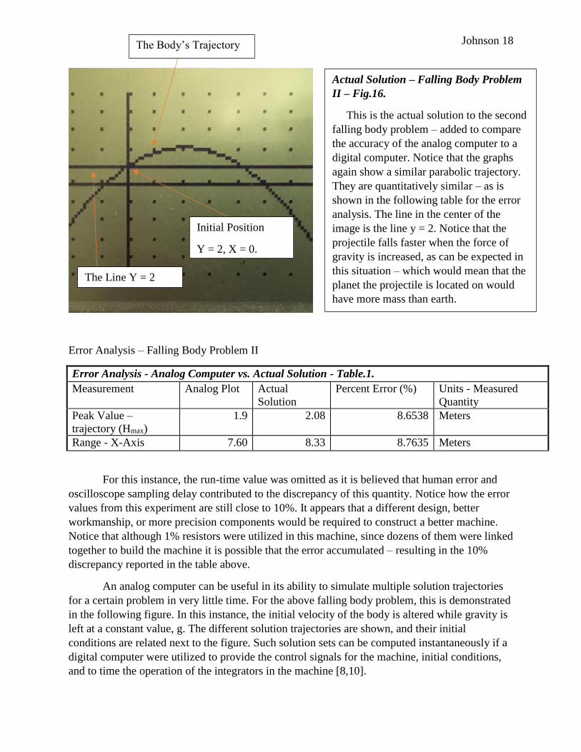
Actual Solution – Falling Body Problem
II – Fig.16.
This is the actual solution to the second
falling body problem – added to compare
the accuracy of the analog computer to a
digital computer. Notice that the graphs
again show a similar parabolic trajectory.
They are quantitatively similar – as is
shown in the following table for the error
analysis. The line in the center of the
image is the line y = 2. Notice that the
projectile falls faster when the force of
gravity is increased, as can be expected in
this situation – which would mean that the
planet the projectile is located on would
have more mass than earth.
The Body’s Trajectory
The Line Y = 2
Initial Position
Y = 2, X = 0.
Page 19
Johnson 19
Third Experiment – Falling body problem solution set for different initial conditions
In addition to being useful as a model of physical systems, analog electronic circuits can be
utilized as a useful classroom tool and apparatus for demonstration purposes. One such
application is detailed in the following section.
The use of Analog Computing with a Chaotic System of Equations
The Lorenz differential equations, a set of three linked differential equations, has a
chaotic solution trajectory under certain initial conditions and input parameters [11]. This system
of equations has the following form:
𝑑𝑥
𝑑𝑡= 10(−𝑥 + 𝑦) Eq. 19.1. Lorenz Equations First Equation.
𝑑𝑦
𝑑𝑡= 28𝑥 − 𝑦 − 𝑥𝑧 Eq. 19.2. Lorenz Equations Second Equation.
𝑑𝑧
𝑑𝑡= −
8
3𝑧 + 𝑥𝑦 Eq. 19.3. Lorenz Equations Third Equation.
These equations form a nonlinear, autonomous three-dimensional system [11]. Such a system
can be demonstrated with the utilization of analog circuits to model the system above.
Soln. #1. Vx = 7.07 m/s,
Vy = 10 m/s.
Soln. #2. Vx = 7.07 m/s,
Vy = 7.07 m/s.
Soln. #3. Vx = 7.07 m/s,
Vy = 3.00 m/s.
Soln. #4. Vx = 7.07 m/s,
Vy = 0.00 m/s.
Four Solution Curves for Falling Body Problem – Fig.17
The analog computer can compute many solution trajectories for the falling body
problem in response to different initial conditions. The y-component of the initial velocity
is altered above to yield a family of such curves. A digital computer can operate the
analog computer so that these solutions can be viewed at once on an oscilloscope/sampler.
Notice the acceleration due to gravity is fixed at 1g (9.8 meters/second = 9.8 volts) and the
initial condition is y = 2, x = 0 (the above graphs are shifted) for all solution trajectories.
Page 20
Johnson 20
The above circuit contains resistors that act as the coefficients in the Lorenz equations.
The first integrator contains two input resistors of 100k ohms each, which have their inputs from
the x and -y inputs. These are summed, negated, and then integrated. The result is ʃ10(-x+y)dt =
x. The same process is executed by the remainder of the circuit. Since each of the integrators has
an output that is proportional to the reciprocal of RinputCfeedback capacitor, the values of the
resistances in the circuit are altered to reflect the relative magnitudes in the above differential
equations. The equation that governs this “scaling” is below.
1
10−6𝑅= 𝑐𝑜𝑒𝑓𝑖𝑐𝑖𝑒𝑛𝑡 𝑖𝑛 𝑎𝑏𝑜𝑣𝑒 𝑒𝑞𝑢𝑎𝑡𝑖𝑜𝑛 Eq. 20. Lorenz Equation Scaled Resistance Values.
This equation leads to the values of 100k ohms in the first circuit above. Furthermore, it can be
utilized to determine that the y-integrator should have resistance values on its input of 35.7k
ohms, 1 Meg ohm, and 10k ohms for the x, -y, and product term -xz/100 respectively.
Furthermore, the values of the input resistances in the final integrator for the z variable are 10k
and 374k Ohms by the same principle.
Since this system is designed, it can be constructed to observe typical solution trajectories
for the differential equation. This was accomplished in November, 2016 for Dr. Chen’s 2552
Introduction to Differential Equations Course at The Georgia Institute of Technology. Dr. Chen
was very generous with his time and assistance, and it was a true honor to be able to show this
experiment to his students when the “chaos” section was studied latter in the fall, 2016 semester.
From this application, it is apparent that analog computers can be utilized in a variety of
settings and contexts. In addition, it is obvious that they can be utilized for demonstration
purposes. Their main limitations include difficulty of programming and limited accuracy. After
these two concerns, a limited range of quantities is also a difficulty to circumvent. However, if
these three problems could be rectified, then analog electronic circuits could be utilized for a
variety of tasks and purposes [10].
Schematic of Lorenz Equation Analog
Circuit Model – Fig. 18.
This image shows the schematic of the
Lorenz equation circuit model, which
calculates the x,-y, and z values of the
solutions to the above set of equations. The
terms are summed and then integrated by
the three summing integrators. The
multipliers on the left-hand side of the
figure provide the nonlinear terms that are
required by the system. The output can then
be viewed in real time on an oscilloscope.
Page 21
Johnson 21
Conclusions
Although analog computation is a viable means to simulate dynamic systems, differential
equations, and other operations, it remains plagued with difficulties. Despite much effort in this
area, the percent error for such machines remains at 10% or so. Perhaps this can be reduced,
maybe in the future. If this were to occur, then there may be specialized applications for such
devices – as in instances where power is at a minimum or where simplicity is required. Until
such time, this area represents a dead end as it is impossible to proceed without great difficulty.
However, this research was not in vain – as it shows that alternate computational paradigms are
possible with different systems of representation, operations on information, and input/output
devices. Furthermore, it was realized that analog computation can model the qualitative
information of a system within 10% of the correct values. Thus, for applications where this error
is negligible or can be tolerated, such devices can be utilized. In addition, analog computers can
show qualitative behavior of differential equations very close to the expected curves as graphed
by a digital computer. If it were possible to eliminate the “patch panel” nature of programing an
analog computer, and to use a digital system to minimize the machine’s error, then it would be
possible to utilize analog computation as a high-speed and concise engineering tool.
In conclusion, this project answered the questions asked in the introductory section. It is
possible, with some moderate difficulty, to design an analog computer and to solve physical
problems on it. It can solve these problems, with an error of about 8%-10% under normal
circumstances. If a large scale analog computer were constructed, great care would have to be
taken in regards to component precision, analog noise, and other unideal aspects, to make such a
system viable and able to perform better than a digital computer. Now in my studies, such a task
is beyond the realm of my abilities. However, this is a perfect springboard for such a future
project. Perhaps it is possible that a carefully designed analog computer may have some use in
the future of research and development, industry, or consumer electronics?
Page 22
Johnson 22
Works Cited
1. Svoboda, James A. and Richard C. Dorf. Introduction to Electric Circuits. Hoboken:
John Wiley & Sons, Inc., 2014. December 2016.
2. Horowitz, Paul, and Winfield Hill. The Art of Electronics. Second ed. New York, NY:
Cambridge UP, 1989.Print. An excellent general electronics reference. Notice the
fundamentals of this paper are based on work from this volume. Furthermore, chapters
three and thirteen touched on analog circuits.
3. Paz, Robert. Analog Computing Technique. Chicago, 2011.
4. Strong, John D. and George Hannauer. A Practical Approach to Analog Computers. Long
Beach, NJ: Electronic Associates Inc., 1962. Print
5. Bryant, Lawrence T. and Louis C. Just. Introduction to Electronic Analog Computing.
Argonne, Il: University of Chicago, 1966. Print.
6. Gililand, Maxwell. Handbook of Analog Computation. Concord, CA: Synchron, Donner,
1967. Print.
7. Goodsell, David. "Old Heathkits Never Die, They Just Get Restored." Nuts and Volts
May 2016: 40-45. Print. This article documented the restoration of a 1959 analog
computer that could run simulations of dynamic systems, ultimately a bouncing ball.
Published in the May, 2016 article of "Nuts and Volts", the operational amplifiers used in
the system employed vacuum tubes. Furthermore, analog op amp circuits were used in
this system with 1N4006 diodes. This article inspired this project, and subsequent
research paper.
8. Ulmann, Dr. Berndt. Hybrid Controller. 10 August 2016. Web Site Article. 28 December
2016.
Page 23
Johnson 23
9. Heathkit, Inc. Operational Manual for the Heath Educational Analog Computer.
Heathkit, 1959. Print.
10. Ulmann, Bernd. Analog Museum. 2016. Web Site. 5 December 2016.
<http://www.analogmuseum.org/english/>.
11. Brannan, James R., William E. Boyce, and Mark A. McKibben. Differential Equations:
An Introduction to Modern Methods and Applications. Third ed. Hoboken, N.J.: Wiley,
2015. Print.
12. George B. Thomas Jr., et al. Thomas' Calculus Early Transcendentals, 3rd ed. Boston,
MA: Pearson, 2014. Print.