Faculty of Engineering and Science Aalborg University Department of Computer Science Join/Leave Protocol for Structured Peer-to-Peer Networks Master Thesis Group B1-215e - 10th semester February 1st - June 10th, 2003
Transcript
Faculty of Engineering and ScienceAalborg University
Department of Computer Science
Join/Leave Protocol for StructuredPeer-to-Peer Networks
Master Thesis
Group B1-215e - 10th semester
February 1st - June 10th, 2003
Faculty of Engineering and ScienceAalborg University
Department of Computer Science
TITLE: Join/Leave Protocol for Structured P2P NetworksMaster Thesis
SEMESTER PERIOD:SSE4, 10th semesterFebruary 1st - June 10th, 2003
The aim of this project is to implement andtest a Peer-to-Peer communication pro-tocol, whose purpose is to assure a ba-sic connectivity in the structured Peer-to-Peer network. The protocol implementa-tion is based on the object-oriented anal-ysis and design (OO&D) methodologiesand it was implemented in C++ Program-ming Language using Standard TemplateLibrary (STL), POSIX threads and sock-ets Application Programmable Interfaces(APIs). Systems tests were conducted toverify conformance to the functional andnon-functional requirements, and its targetenvironment. The experimental results in-dicate that functional and non-functional(performance) requirements are met andfurther improvements are proposed.
Preface
This report has been written by project group B1-215e as a report for the second part ofthe Master Thesis in the International Masters Program in Software Systems Engineeringof the Faculty of Engineering & Science, in the Computer Science Department at AalborgUniversity, Denmark, during the period from the 1st of February to the 10th of June,2003.
This report is directed to people interested in distributed systems and peer-to-peer appli-cations.
Figures, tables and formulas in the report are numbered in succession inside each chapter.Cross-references to formulas, figures, tables and appendix are written directly in the text.Cross-references to source material are specified with square brackets after the part of thetext, where they are used, e.g. [2].
The source code of the Join/Leave protocol can be found at the following location:http://www.cs.auc.dk/∼aras/sse4/
In general, Peer-to-Peer (P2P) systems are distributed systems without any centralized control orhierarchical organization, where Peer-to-Peer is a system architecture model in which each partyhas the same capabilities and either party can initiate a communication session. Other models withwhich P2P system architecture model might be contrasted include the client/server model and themaster/slave model. In computer networking, master/slave is a model for a communication pro-tocol in which one device or process (known as the master) controls one or more other devices orprocesses (known as slaves). The client/server model describes the relationship between two com-puter programs in which one program, the client, makes a service request to another program, theserver, which fulfills the request. The main distinction between P2P and master/slave, client/servermodels is that in P2P system architecture model each machine can be both, a server and a clientwithin the context of a given application. The machine which can serve as a server and a clientis called the Peer. The analogy of a Peer-to-Peer system architecture model could be a telephonesystem where any person can call another person. Then the telephone model could be called aPerson-to-Person system architecture model, where Person could be a receiver of a call or a caller,and no other Person has more privileges to make a call or receive a call. Same ideology can beapplied to a P2P system architecture model where Peers are connected in a network and all Peersare working and communicating on an equal basis. The example of a P2P network can be seen inFigure1.1.
Master/Slave
Master/Slave
Master/Slave
Master/Slave
Master/Slave
Figure 1.1: Example of a Peer-to-Peer network. Rectangular shapes represents the Peers, a linefrom one Peer to another represents a communication link.
5
1.1.2 Peer-to-Peer Systems Definition
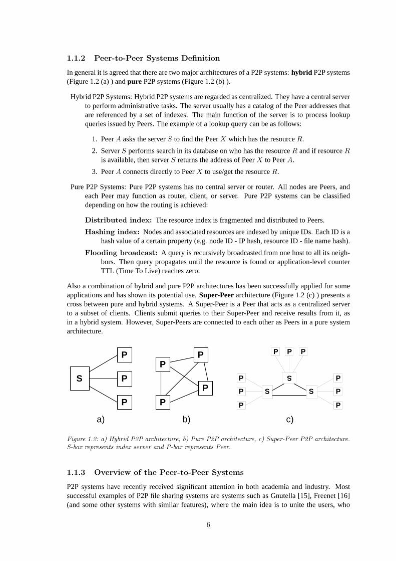
In general it is agreed that there are two major architectures of a P2P systems:hybrid P2P systems(Figure1.2(a) ) andpure P2P systems (Figure1.2(b) ).
Hybrid P2P Systems: Hybrid P2P systems are regarded as centralized. They have a central serverto perform administrative tasks. The server usually has a catalog of the Peer addresses thatare referenced by a set of indexes. The main function of the server is to process lookupqueries issued by Peers. The example of a lookup query can be as follows:
1. PeerA asks the serverS to find the PeerX which has the resourceR.
2. ServerS performs search in its database on who has the resourceR and if resourceRis available, then serverS returns the address of PeerX to PeerA.
3. PeerA connects directly to PeerX to use/get the resourceR.
Pure P2P Systems: Pure P2P systems has no central server or router. All nodes are Peers, andeach Peer may function as router, client, or server. Pure P2P systems can be classifieddepending on how the routing is achieved:
Distributed index: The resource index is fragmented and distributed to Peers.
Hashing index: Nodes and associated resources are indexed by unique IDs. Each ID is ahash value of a certain property (e.g. node ID - IP hash, resource ID - file name hash).
Flooding broadcast: A query is recursively broadcasted from one host to all its neigh-bors. Then query propagates until the resource is found or application-level counterTTL (Time To Live) reaches zero.
Also a combination of hybrid and pure P2P architectures has been successfully applied for someapplications and has shown its potential use.Super-Peerarchitecture (Figure1.2 (c) ) presents across between pure and hybrid systems. A Super-Peer is a Peer that acts as a centralized serverto a subset of clients. Clients submit queries to their Super-Peer and receive results from it, asin a hybrid system. However, Super-Peers are connected to each other as Peers in a pure systemarchitecture.
S
P
P
P
a)
P
P
P
P
b)
S
P
P
P
S
P
P
P
S
P P P
c)
Figure 1.2: a) Hybrid P2P architecture, b) Pure P2P architecture, c) Super-Peer P2P architecture.S-box represents index server and P-box represents Peer.
1.1.3 Overview of the Peer-to-Peer Systems
P2P systems have recently received significant attention in both academia and industry. Mostsuccessful examples of P2P file sharing systems are systems such as Gnutella [15], Freenet [16](and some other systems with similar features), where the main idea is to unite the users, who
6
wants to share the files, into a P2P network where users can easily find what they want, get whatthey want and give what they want. Another kind of P2P systems are systems that utilizes unusedor wasted CPU-cycles of the idle machines in a P2P network. Those systems are mostly used byscientists who needs to get the results within a reasonable time for parallelizable computationalproblems that require a lot of CPU-cycles. Examples of such a systems could be SETI@home [6],THINK [ 13] and distributed.net [14].
SETI@home: The Search for Extraterrestrial Intelligence. They scan the sky using a largeradio telescope and record the signals in a certain frequency. The computational problemhere is that they must calculate Fast Fourier Transformation (FFT) of each signal to performthe analysis on the power spectrum of the signal. By analyzing the power spectrum of asignal they want to find the ”unusual” patterns in a signal, as a proof that extraterrestrialintelligence exists.
SETI@home is a master/slave distributed calculation system where master distributes workto the slaves. Master splits the signals into the work units, where length of the signal isaround 100 seconds (a file size is around 340kb) and then distributes them to the clients. Onthe average home computer the processing of a data (one work unit) should take between 10and 50 hours.
THINK: THINK project is a drug discovery system. System analyses each of the hundredsof millions of molecules to see if they are likely to interact with a target protein. THINKcalculates and studies the many possible shapes, or conformers, the molecule might adoptinteracting with the protein.
THINK is a master/slave distributed calculation system and like SETI@home, they havededicated master server which distributes tasks to the slaves. The work unit contains ap-proximately 10Kb of data and the CPU-time required varies from 4 hours to several days.
distributed.net: distributed.net project is based on solving mathematical problems such asOptimal Golomb Ruler, RSA, etc. At the moment when this report has been written thedistributed.net was solving RC5-72, which is 72-bit RSA Data Security Secret Key Chal-lenge. It is also master/slave distributed calculation system. The only difference compare toprevious examples is that a slave can control how much work he can get depending on theavailable resources.
Common characteristic of those systems is that they are based on a client/server architecture wherepeople around the world offer their spare CPU-cycles for a particular computational problem. Themain drawback in the systems mentioned above is that a central server must be really powerful tobe able to serve all the clients.
A more challenging approach to the distributed calculation could be to use a pure P2P architecturewhere all the clients are equal and allow everybody in the P2P network issue the computationalproblems, meaning that everybody can use others spare CPU-cycles for theirs purposes. One ofsuch a systems is a distributed heterogeneous calculation platform FROST [1] which was devel-oped in the Aalborg University.
7
1.2 The FROST System
The FROST system [1] was designed and implemented in the Aalborg University. The aim wasto develop an API that will aid a programmer in developing applications such as SETI@home[6], THINK [ 13] and distributed.net [14]. From the FROST perspective the programmer is auser which defines a computational problem, defines how to split the computational problem intoseveral pieces, or work units, that can be processed independently, and finally defines how tocombine the results when they have been processed. Moreover, a user has to specify the algorithmthat performs the calculations on the work units. Administration of the network communicationbetween the machines, distribution of the work units to the machines in the FROST network andother administrative tasks are hidden from the user and are performed by the FROST system. Workunits can be distributed only to the machines that are members of the FROST network. A machineis said to be a member of the FROST network if that machine has a FROST software running andother participants of the FROST network can communicate with that machine and use the CPU-cycles of that machine for solving some computational problem. The FROST network is basedon a pure P2P architecture where all the machines are working on an equal basis, meaning thatanybody in the network can use or give spare CPU-cycles to each other. Moreover, the machines ornodes in the FROST network are non-dedicated workstations, which are used for a daily purposes.Whereas the FROST system on these workstations run with low priority to assure that FROSTuses only those CPU-cycles that are unused.
1.2.1 Limitations of the FROST System
One of the limitations of the FROST system is that a current implementation scales only to a lo-cal area network (LAN). The FROST developers indicated that a problem in scaling the FROSTsystem is the bottleneck induced by master and information sharing. The bottleneck induced bymaster is a situation when a master node must handle thousands of clients and thus the master be-comes a bottleneck either because of the network bandwidth or speed of a master node. Anotherproblem in scaling the FROST system is the information sharing, since all the nodes in the FROSTnetwork has to share the information required for the load balancing and other administrative tasksand it is currently done by using broadcast communication. It is normal to use broadcast commu-nication on the local area network, but it is unprofitable for the Internet wide communication.
1.2.2 Problem Statement
A scalable solution for the FROST system was proposed in [2] where the Join/Leave protocol wasdesigned and verified using the SPIN [18, 19] verification tool. This work is a continuation of aprevious work [2] and there are two main goals that motivate this study:
1. Prototype Implementation.Prototyping is an efficient software development technique whichhelps to better understand the environment and the requirements being addressed. A proto-type is a demonstration of what’s actually feasible with existent technology, and where thetechnical weak spots still exists. In this part the main goal is to implement a prototype ofthe Join/Leave protocol and prepare it for the system testing.
2. System Testing.System testing is an important process for assuring software quality in anenvironment of complex defect-prone components. In general, system testing focuses on thecomplete system, its functional and non-functional requirements, and its target environment.The following system tests will be conducted:
Functional testing. Functional testing, also called requirements testing, tests if the sys-tem perform as promised by the requirements specification.
8
Performance testing. Performance testing is used to test if the non-functional require-ments are met. Two types of performance tests were conducted:
Stress tests: The purpose of the stress tests is to evaluate the system when stressedto its limits over a short period of time.
Timing tests: The purpose of the timing tests is to validate conformance to behav-ioral and performance constraints and evaluate if the system is fast enough.
1.3 Join/Leave Protocol Concepts
In this section some required concepts, which were defined in the previous work [2] will be intro-duced.
1.3.1 FROST Architecture Model
The structured indirect communication model was chosen because it promises to avoid the probleminduced by master and the information sharing can be done efficiently. The nodes in such a modelform the groups of nodes, where each group has one master node. Information between the nodesis shared inside the group, whereas group masters can share the information between other groupmasters as can be seen in Figure1.3. Another advantage of the model is that it is a decentralizedmodel meaning that there is no need to invest in dedicated machines.
G 1
G 2
G 3
G 4
Figure 1.3: Simple structured indirect communication architecture model with 4 groups of nodes.
The basic structured indirect communication model was modified by removing the root nodefrom the architecture, with intent to remove the central point of failure in the model. Then theFROST architecture model will look as presented in Figure1.4. The FROST architecture modelcan be described using 3 parameters:
Base: Baseparameter gives an upper bound for the number of slaves in a group of nodes. Forexample, theBaseof the architecture model presented in Figure1.4 is: Base= 4, thus thefictitious nodeN0 can have a maximum of4 slaves and they areN1, N2, N3 andN4. Thisrule holds for all master nodes (N1,N2, etc.) in the architecture.
Level: Level parameter gives the number of levels in the model. For example, theLevel of thearchitecture model presented in Figure1.4 is: Level = 3, meaning that model has threehierarchical levels starting from levelL1 to L3.
Size: Sizeparameter gives the number of nodes in the model. The size can be calculated usingthe following equation:1−B·l
1−B − 1, wherel = BL, B - Base, L - Level. For example, theSizeof architecture model presented in Figure1.4 is: Size= 84.
The FROST model could scale to a large number of nodes, for instance if base and level of amodel isB = 100 andL = 7 respectively, then the sizeS ≈ 1014, which is very large number
9
of nodes and the worst case number of hops from one node to another is onlyHOPS= 13, whereHOPS= 2 · L− 1. For example, in Figure1.4the worst case number of hops isHOPS= 5.
The nodes in the model are organized according to the performance of nodes, meaning that higherperformance nodes are locatedhigher in the hierarchy, for instance in Figure1.4, nodesN1, ..., N4
have highest performance and are located in levelL1, nodes with low performance are located inlevelL3.
The following describes the data structures used by the Join/Leave protocol:
Static performance (SP): SPis a static node performance.
Global performance (GP): GP is a global performance of a group including subgroups. Aknowledge about a global performance will support a decision making on where the newnodes should join to sustain as well balanced FROST architecture as possible. When theFROST system is operational, theGPvalues of the highest level nodes should be close. Forinstance, if nodesN1, N2 andN3 are from highest level, then:GP1 ≈ GP2 ≈ GP3. Aglobal performance is maintained by each node in the FROST system and is calculated asshown in equation1.1. Note, that when a node has no slaves, the sum evaluates to zero andtheGP is equal to a static node performanceSP.
GPi = SPi +∑
j∈slaves(GPi)
GPj (1.1)
GPi - global performance of nodeNi,
GPj - global performance of nodeNj , nodeNj is a slave of masterNi,
For example, consider the fragment of a FROST system in Figure1.5. The calculation ofglobal performanceGP1 of nodeN1 is as follows: using the equation1.1and following thebottom-up direction in the FROST system the global performance of nodeN1 is:GP1 = GP2 + GP3 + GP4, whereGP2 = GP5 + GP6 + GP7 andGP4 = GP8 + GP9.
Base (B): B is a constant which defines the base of a FROST architecture. The base value isan upper bound for the number of slaves a master can have. For instance, in the FROST
10
architecture fragment in Figure1.5, the base isB = 3, and the maximum number of slaveseach node can have is3. Thus, nodeN1 and nodeN2 has maximum number of slaves, nodeN4 could have one more slave and nodeN3 could have three more slaves.
1
2 3 4
5 6 7 8 9 GP
5 GP
6 GP
7 GP
8 GP
9
GP 3 =SP
3
GP 2
GP 4
GP 1
Figure 1.5: The FROST system fragment.
Level (level): levelparameter shows to which level in the FROST architecture a particular nodebelongs. For instance, assume that in Figure1.5nodeN1 belongs to the highest level, thenlevel parameter for nodeN1 is level= 1, N2 level level= 2, N5 level level= 3, etc.
Local slaves (s): s parameter shows how many slaves particular node has. For instance, inFigure1.5nodeN1 has three slavess = 3, nodeN3 has no slavess = 0, etc.
Slave address list (SAL): SALis a list of the slave addresses. TheSALlist is the fundamen-tal data structure in the FROST system, since it specifies the relations between the nodes inthe FROST architecture.
11
Chapter 2
Join/Leave ProtocolImplementation
2.1 The Task
2.1.1 Purpose
The purpose of the Join/Leave protocol is to handle the node joins and departures in the FROSTnetwork, whose system architecture and concepts were described in [2]. In general the Join/Leaveprotocol can be divided into two parts based on the function it should perform:
Join: The Join/Leave protocol must assure that a node which joins the network will be organizedin the hierarchy according to its static performance measure -SP, which represents the rela-tion between the available node resources (bandwidth, CPU and main memory) and its placein the hierarchy. If nodes are arranged according to their static performance, the workloadto maintain the network structure will be accordingly distributed between the nodes.
Leave: When nodes leave the network (voluntarily or by failing) the Join/Leave protocol hasto assure the integrity of the communication architecture by appropriately rearranging therelated nodes in the network.
The Join/Leave protocol should be used as the communication component of the FROST systemfirst described in [1].
2.1.2 Corrections to the Analysis
Some corrections have been made from the analysis and design [2] of the Join/Leave protocol:
Static performance (SP): Previously, the static node performance was derived by using thestatic performance parameters: bandwidth, CPU and main memory. However, the networkbandwidth (and not storage space or computation time) is presently the most limited re-source in P2P networks [4]. Any node joining the network must send at least some numberof maintenance messages. According to the join procedure described in [2] the nodes startjoining the network from the highest level and that would yield higher traffic of the main-tenance messages at the higher levels of the FROST communication network architecture.The implication is that the static node performance measure can be derived considering onlythe bandwidth. Thus, the nodes which have more bandwidth will join the higher levels andnodes with less bandwidth will join the lower levels of the network architecture.
Join procedure: The joining procedure is performed by nodeNjoin and was previously de-fined as follows:
12
1. Get a list of the highest level nodes from nodeN0.
2. Ask any node in the highest level where to join. (Answer is an address of some nodeNask).
3. Ask nodeNask where to join. (Answer is an address of some nodeNask).
4. Repeat 3, untilNask accepts nodeNjoin. (Njoin is a leaf node after the join phase).
5. Trigger the adaptation to the network if necessary. (Adaptation follows the bottom-updirection).
An optimization was made to the join procedure presented. Instead of joining at the bottomof the tree and then triggering the adaptation to the network, the joining node could be awareof the possible adaptation while performing step 3; i.e. if it turns out that theSPvalue ofthe joining nodeNjoin is higher than of nodeNask, then nodeNjoin could trigger the adap-tation to the network by pushing the nodeNask downwards. Thus the overall effect of thisnew scheme should reduce the rate of change in the network and thus the number of mainte-nance messages, which in turn will reduce the bandwidth consumption. To summarize, theoptimized joining procedure is performed as follows:
1. Get a list of the highest level nodes from nodeN0.
2. Ask any node in the highest level where to join. (Answer is an address of some nodeNask).
3. Ask nodeNask where to join (answer is an address of some nodeNask) and trigger theadaptation to the network if necessary. (Adaptation follows the top-down direction).
4. Repeat 3, untilNjoin joins.
2.1.3 Quality Goals
Table 2.1 shows the prioritization of design criteria. A special weight is placed on reliability,correctness and usability since these characteristics are critical for whether the system will be usedat all. The main intent to implement a prototype of the Join/Leave protocol is to test and measurethe performance of the protocol. It should be possible to test the system for ensuring that thesystem performs its intended functions. Also the system should be flexible and comprehensible to
reduce the cost of modification to the protocol implementation if necessary. To concentrate on thefunctionality of the protocol and ability to evaluate it all other characteristics have been prioritizedlower or irrelevant. However it should be noted that some characteristics (i.e. security, portability,interoperability) that were left out have to be considered as important in later development of theJoin/Leave protocol:
Secure. The maintenance protocols are especially susceptive to the DoS (Denial of Service)attacks. Since the Join/Leave protocol is intended to operate Internet wide there is a highrisk of such attacks.
Portable. The protocol should be able to operate on various technical platforms to increase thenumber of potential users of the FROST system [1].
Interoperable. This characteristic is important when coupling the Join/Leave protocol withFROST system [1].
2.2 Technical Platform
Equipment. The computerized system is designed for use on the non-dedicated workstationsthat are interconnected via network (LAN, Internet, etc.). There is no need to have anexpensive high speed machine to assure the basic connectivity in the FROST network sincethe main limitation is the available bandwidth. Thus, the minimum requirements are: non-archaic PC (Personal Computer) with NIC (Network Interface Card) or modem installedand an active connection to the network.
System Software. Linux OS (Operating System) will be used to implement, test and run theJoin/Leave protocol. The design is based on implementing the system in C++ programminglanguage. The C++ programming language has to have an API (Application ProgrammableInterface) to POSIXthreadsandsockets.
Design Language. The design is based on the UML (Unified Modeling Language) notation.
2.3 Architecture
2.3.1 Process Architecture
The physical architecture of the FROST network managed by the Join/Leave protocol (Frost Clientcomponent) is shown in Figure2.1. A Node refers to a PC which fulfills the requirements ofthe technical platform and uses the FROST client software to be a part of the FROST network.Nodes communicate using TCP/IP Internet protocol, where reliable data delivery is provided bya connection-oriented TCP transport protocol. Technical platform component has an interface tothe various OS components, including POSIXthreadsandsockets. The Frost Client componentcomprises the model and functions of the Join/Leave protocol and is responsible for the basicconnectivity in the FROST network.
14
Node
Frost Client
Technical Platform
Node
Frost Client
Technical Platform
Node
Frost Client
Technical Platform Node
Frost Client
Technical Platform
TCP/IP
TCP/IP TCP/IP
Figure 2.1: Deployment Diagram. The FROST network of four nodes. Dashed arrows representdependency associations between nodes.
The Frost Client component could be decomposed using a design pattern in Figure2.2as follows:
User Interface Component. A part of a system implementing the interaction with users.
System Interface Component. A part of a system implementing the interaction with othersystems.
Model Component. A part of a system that implements a model of the Join/Leave protocol.
15
Function Component. A part of a system that implements functional requirements of theJoin/Leave protocol.
2.4 Model Component
The Model component is a part of a Join/Leave protocol that handles data storage. The purpose ofthe component is to control and deliver data to functions, interfaces, users and other computerizedsystems. The event Table2.2 for the Model component follows from the use case diagram of theFrost client component shown in Figure2.3. As can be seen from the event table there are three
Frost User
Join
Leave
Fail
Frost Client
Figure 2.3: Use Case Diagram for the Frost client component.
Table 2.2: Event table for the Model component. ? - multiple modifications to an object; + -onetime modification to an object.
main events that causes the change of state in a model. The system is in thejoined state whena node is connected to the FROST network and the system is in theleft or failed state if a nodehas disconnected from the FROST network either by voluntarily leaving or by failing respectively.The behavioral pattern of this situation can be seen in Figure2.4.
2.4.1 Structure
The class diagram for the Model component is shown in Figure2.5. All classes are described inthe following.
2.4.2 Classes
The following contains a specification of the classes from the class diagram in Figure2.5.
16
/ join
Joined
Left
Failed
/ leave
/ fail
/ terminate / join
Figure 2.4: State Chart Diagram for the Model component.
ServerClient AddrList SlaveList
Connector ConnQueue Expector
1 *
1
1
1
1
1 1
1
*
Figure 2.5: Class Diagram for the Model component.
Class ServerClient
Purpose: It is the main class in the system, it contains the data model of the Join/Leave protocol.The rest of the Model component classes are the parts of this class (aggregation relation) ascan be seen from the class diagram in Figure2.5. Also, it has a control over the Functioncomponent (see Figure2.2) by being able to use its functions accordingly.
Attributes: To classify the attributes by their purpose, the attributes are represented in distincttables: attributes that are fundamental for the Join/Leave protocol are shown in Table2.3,attributes that are used to interact with Function component (see Section2.5) are shown inTable2.4and some other important attributes of the class are shown in Table2.5.
Attribute Type PurposeID int The unique identifier of a node.SP int The static performance parameter of a node.GP int The global performance parameter of a node.level int Shows to which performance level a particular node
belongs.base const int The base of the FROST architecture.SAL AddrList ? The list which contains the addresses of the slave
nodes.
Table 2.3: Join/Leave protocol specific attributes. Abbreviation ”?” represents a pointer to theobject leftwards.
17
Attribute Type Purposeacceptor Acceptor ? See section 2.5.2 for more details.queue QueueHandler ? See section 2.5.2 for more details.vips VIPHandler ? See section 2.5.2 for more details.joiner JoinHandler ? See section 2.5.2 for more details.askers AskersHandler ? See section 2.5.2 for more details.pusher PushHandler ? See section 2.5.2 for more details.leaver LeaveHandler ? See section 2.5.2 for more details.failer FailHandler ? See section 2.5.2 for more details.master MasterHandler ? See section 2.5.2 for more details.SHL SlaveList ? The list which contains pointers to the SlaveHandler
objects (see section 2.5.2 for more details about theSlaveHandler class).
Table 2.4: Attributes that are used to interact with the Function component. Abbreviation ”?”represents a pointer to the object leftwards.
Attribute Type Purposeconnector Connector ? See Connector class for details.expector Expector ? See Expector class for details.cq ConnQueue ? The ConnQueue class contains a list of the Connec-
tion objects (see class Connection for details). Thecq list is the waiting list for the active connectionsthat were accepted by the Acceptor (see in section2.5.2) thread and added by Expector object (see Ex-pector class for details). The list is processed by theQueueHandler (see section 2.5.2) thread.
vip ConnQueue ? The vip list is a waiting list for the active connec-tions that were accepted by the Acceptor thread andadded to the vip list by the Expector object. The listis processed by the VIPHandler (see section 2.5.2)thread.
AskWL AddrList ? The AskWL list is a waiting list for the nodes that arewaiting for an answer where to join. Nodes are addedto the list by the QueueHandler thread and pro-cessed by the AskersHandler thread. (See section2.5.2 for more details.)
mutex pthread mutex t mutex is a mutual exclusion device, which is usedfor protecting shared data structures from concurrentmodifications.
mutex pl pthread mutex t mutex pl is a mutual exclusion device, which is usedto control the concurrent executions of the functions(threads) provided by the Function component.
Table 2.5: Other attributes. Abbreviation ”?” represents a pointer to the object leftwards.
18
Operations: The class operations are summarized in Table2.6.
Operation Purposejoin() This operation is used to join the FROST network.leave() This operation is used to voluntarily leave the FROST network.fail() This operation is used to simulate a fail situation.spawn acceptor() Starts Acceptor thread. See section 2.5.2 for details.spawn queue() Starts QueueHandler thread. See section 2.5.2 for details.spawn vip() Starts VIPHandler thread. See section 2.5.2 for details.spawn joiner() Starts JoinHandler thread. See section 2.5.2 for details.spawn askers() Starts AskersHandler thread. See section 2.5.2 for details.spawn pusher() Starts PushHandler thread. See section 2.5.2 for details.spawn leaver() Starts LeaveHandler thread. See section 2.5.2 for details.spawn failer() Starts FailHandler thread. See section 2.5.2 for details.spawn master() Starts MasterHandler thread. See section 2.5.2 for details.spawn slave() Starts SlaveHandler thread. See section 2.5.2 for details.
Table 2.6: ServerClient operations.
Behavior: The general behavioral pattern of this class can be seen in Figure2.4. An interactionbetween the actor and theServerClient class is shown in Figure2.6. Two use cases are
ServerClient
Frost User
join()
joiner:JoinHandler
spawn_joiner()
status
join()
cq:QueueHandler
vip:QueueHandler
spawn_queue()
spawn_vip()
master:MasterHandler
slv1:SlaveHandler
spawn_master()
spawn_slave()
fail()
exit()
exit()
exit()
exit()
exit()
askers:AskersHandler
spawn_askers()
exit()
exit()
Figure 2.6: Sequence Diagram with concurrent objects.
shown: Join use case and Fail use case. Sequence diagram in Figure2.6 also shows the
19
creation and lifetime of certain objects involved in the use cases.
Class Connector
Purpose: Given an Internet address theConnectorclass is responsible for opening a connectionto a remote node.
Attributes :
Attribute Type PurposePORT const int It is a well known port used for communication in a
FROST network.
Table 2.7: Connector attributes.
Operations :
Operation Purposeconnect to() Given an Internet address it opens a connection to a remote node.
The operation returns sockaddr in structure and socket descrip-tor fd.
Table 2.8: Connector operations.
Class AddrList
Purpose: This class is used to store and maintain a list of Internet addresses.
Attributes :
Attribute Type Purposeal vector<uint32 t> al is a STL (Standard Template Library) con-
tainer used to store the 32-bit Internet ad-dresses.
bounded const bool Determines if a list is bounded or not.base const int The base of the FROST architecture. If al
list is bounded then base parameter is usedto check the boundaries of al list.
mutex pthread mutex t mutex is a mutual exclusion device, which isused for protecting the al list from concurrentmodifications.
wl not empty pthread cond t wl not empty is a condition variable, whichis used to signal the waiting thread if al listchanged its state from empty to not empty.
Table 2.9: AddrList attributes.
20
Operations :
Operation Purposeadd() This operation is used to add an Internet address to the al list.rem() This operation is used to remove an Internet address from the al
list.get() This operation is used to retrieve an Internet address from the al
list.copy() This operation is used to make a copy of the al list.clear() This operation is used to remove all elements from the al list.getSize() This operation is used to get the size of the al list.
Table 2.10: AddrList operations.
Class Expector
Purpose: This class is derived from the base classAddrList and inherits all the attributes andoperations from theAddrList class. However, additional functionality is added to this class.If a node is expecting a connection from a particular remote node or nodes then theExpectorclass is responsible for storing the Internet addresses of the expected nodes. When theAcceptor accepts the new connectionExpector verifies if the connection is expected ornot. If connection is expected, thenExpector adds aConnection object to thevip queue(classConnQueue), otherwise aConnection object is added to a conventional queuecq(classConnQueue).
Attributes :
Attribute Type Purposemaster uint32 t If node is expecting a connection from the master
node, then an Internet address of the mater node isstored in the master attribute.
Table 2.11: Expector attributes.
Operations :
Operation Purposeexp master() This operation is used to set the master attribute with an Internet
address.exp slave( ) This operation is used to add an Internet address to the al list.isExpected() This operation is used to determine if a given address addr :
addr = master or addr ∈ al list. If one of the two statements istrue then a remote node with address addr is expected. Returnvalue is true if node is expected.
Table 2.12: Expector operations.
21
Class SlaveList
Purpose: This class is used to store and maintain a list of pointers to activeSlaveHandlerthreads (see section2.5.2for SlaveHandlerclass details).
Attributes :
Attribute Type Purposesl vector<SlaveHandler ? > sl is a STL (Standard Template Library)
container used to store pointers to theSlaveHandler objects.
mutex pthread mutex t mutex is a mutual exclusion device, which isused for protecting the sl list from concurrentmodifications.
Table 2.13: SlaveList attributes.
Operations :
Operation Purposeadd() This operation is used to add a SlaveHandler object pointer to the sl list.rem() This operation is used to remove a SlaveHandler object pointer from the
sl list.get() This operation is used to retrieve a SlaveHandler object pointer from the
sl list.clear() This operation is used to remove all elements from the sl list.getSize() This operation is used to get the size of the sl list.
Table 2.14: SlaveList operations.
Class ConnQueue
Purpose: ConnQueueclass implements the FIFO buffer ofConnection objects (see SystemInterface component in section2.6for details aboutConnectionclass).
Attributes :
Attribute Type Purposeconn queue list<Connection ? > conn queue is a STL (Standard Template Li-
brary) container used to store pointers to theConnection objects.
queue mutex pthread mutex t queue mutex is a mutual exclusion device,which is used for protecting the conn queuebuffer from concurrent modifications.
queue not empty pthread cond t queue not empty is a condition variable,which is used to signal the waiting thread ifconn queue buffer is not empty.
Table 2.15: ConnQueue attributes.
22
Operations :
Operation Purposeadd() This operation is used to add a Connection object pointer to the
conn queue buffer.rem() This operation is used to remove a Connection object pointer from the
conn queue buffer.pop() This operation is used to retrieve the first element from the conn queue
buffer.clear() This operation is used to remove all elements from the conn queue buffer.getSize() This operation is used to get the size of the conn queue buffer.
Table 2.16: ConnQueue operations.
2.5 Function Component
The Function component implements the functional requirements of the Join/Leave protocol de-scribed in [2]. In this section the functional requirements will be transformed into a collection ofoperations, each of which is tied to a new class in the Function component.
2.5.1 Structure
The class diagram for the Function component is shown in Figure2.7. Each class that implementsan operation is derived from the abstract base classThread, which also implements a systeminterface to the POSIX threads. The implication is that each operation has its own executionthread and thus each operation could be executed concurrently with other operations. All classesare described in the following.
Figure 2.7: Class Diagram for the Function component.
23
2.5.2 Classes
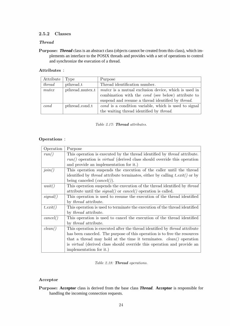
Thread
Purpose: Threadclass is an abstract class (objects cannot be created from this class), which im-plements an interface to the POSIX threads and provides with a set of operations to controland synchronize the execution of a thread.
Attributes :
Attribute Type Purposethread pthread t Thread identification number.mutex pthread mutex t mutex is a mutual exclusion device, which is used in
combination with the cond (see below) attribute tosuspend and resume a thread identified by thread.
cond pthread cond t cond is a condition variable, which is used to signalthe waiting thread identified by thread.
Table 2.17: Thread attributes.
Operations :
Operation Purposerun() This operation is executed by the thread identified by thread attribute.
run() operation is virtual (derived class should override this operationand provide an implementation for it.)
join() This operation suspends the execution of the caller until the threadidentified by thread attribute terminates, either by calling t exit() or bybeing canceled (cancel()).
wait() This operation suspends the execution of the thread identified by threadattribute until the signal() or cancel() operation is called.
signal() This operation is used to resume the execution of the thread identifiedby thread attribute.
t exit() This operation is used to terminate the execution of the thread identifiedby thread attribute.
cancel() This operation is used to cancel the execution of the thread identifiedby thread attribute.
clean() This operation is executed after the thread identified by thread attributehas been canceled. The purpose of this operation is to free the resourcesthat a thread may hold at the time it terminates. clean() operationis virtual (derived class should override this operation and provide animplementation for it.)
Table 2.18: Thread operations.
Acceptor
Purpose: Acceptor class is derived from the base classThread. Acceptor is responsible forhandling the incoming connection requests.
24
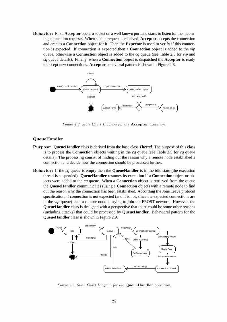
Behavior: First,Acceptoropens a socket on a well known port and starts to listen for the incom-ing connection requests. When such a request is received,Acceptor accepts the connectionand creates aConnectionobject for it. Then theExpector is used to verify if this connec-tion is expected. If connection is expected then aConnection object is added to thevipqueue, otherwise aConnectionobject is added to thecq queue (see Table2.5 for vip andcq queue details). Finally, when aConnectionobject is dispatched theAcceptor is readyto accept new connections.Acceptor behavioral pattern is shown in Figure2.8.
Socket Opened
/ run(),create socket
Connection Accepted
/ got connection
/ cancel
Added To vip
/ is expected?
Added To cq
/ listen
[expected] [!expected]
Figure 2.8: State Chart Diagram for the Acceptor operation.
QueueHandler
Purpose: QueueHandlerclass is derived from the base classThread. The purpose of this classis to process theConnection objects waiting in thecq queue (see Table2.5 for cq queuedetails). The processing consist of finding out the reason why a remote node established aconnection and decide how the connection should be processed further.
Behavior: If the cq queue is empty then theQueueHandler is in the idle state (the executionthread is suspended).QueueHandler resumes its execution if aConnectionobject or ob-jects were added to thecq queue. When aConnectionobject is retrieved from the queuetheQueueHandlercommunicates (using aConnectionobject) with a remote node to findout the reason why the connection has been established. According the Join/Leave protocolspecification, if connection is not expected (and it is not, since the expected connections arein the vip queue) then a remote node is trying to join the FROST network. However, theQueueHandlerclass is designed with a perspective that there could be some other reasons(including attacks) that could be processed byQueueHandler. Behavioral pattern for theQueueHandlerclass is shown in Figure2.9.
Idle
/ run()
Active
[cq !empty]
[cq empty]
Connection Fetched
/ cq.pop()
Added To AskWL Connection Closed
[join] / reply to wait
/ AskWL.add()
Reply Sent
/ close connection
/ done
Do Something
[other reasons] / done
/ cancel
/ cancel
Figure 2.9: State Chart Diagram for the QueueHandler operation.
25
VIPHandler
Purpose: VIPHandler class is derived from the base classThread. The purpose of this classis to process theConnectionobjects waiting in thevip queue (see Table2.5 for vip queuedetails). The reason to have an additional queue together with the conventionalcq queue isto provide the means of almost immediate processing of connections that are expected to beestablished.
Behavior: Same as withQueueHandler the VIPHandler is suspended if a queue it has toprocess is empty and it will be resumed when queue is not empty. There are two types ofexpected connections, either the connection is meant to be with a new slave or a new master.If connection established is with new slave then aSlaveHandlerobject is created to handlea Connection, otherwise aMasterHandler object is created. Behavioral pattern for theQueueHandlerclass is shown in Figure2.10.
Idle / run()
/ cancel
Active
[vip !empty]
[vip empty]
Connection Fetched / vip.pop()
[master] / spawn_master()
MasterHandler Started
/ done
/ cancel
SlaveHandler Started
[slave] / spawn_slave()
/ done
Figure 2.10: State Chart Diagram for the VIPHandler operation.
JoinHandler
Purpose: JoinHandler class is derived from the base classThread. JoinHandler is responsiblefor joining the FROST network.
Behavior: When JoinHandler is started, first, it contacts the discovery server (nodeN0) toretrieve a list of nodes located at the highest level of the FROST architecture. One nodeis randomly chosen from a list to ask where to join. If, however, a chosen node is notresponding then there is a possibility to choose another node from a list. After a queryis dispatched a node waits for an answer about further join instructions. Since the FROSTnetwork is dynamic the answer could be provided by another node which took responsibilityto process asking node. Behavioral pattern for theJoinHandler class is shown in Figure2.11. The are three types of replies an asking node could receive:
Ask next: It says that there are no vacant positions in a group and a node has to ask thenext group master, which is chosen by a current group master. The next master anasker has to contact will be a slave node with min(GP) value in a current group. Thereply includes an address of a chosen slave (next master).
Join granted: ”Join granted” reply is sent if current master has a vacant position in agroup and asker is welcome to join. This reply also indicates that theSPvalue of themaster node is larger than asker’s and there was no need for adaptation.
26
Join granted (push): This reply indicates that theSPvalue of an asker node is largerthan master’s and that master is ready to concede its place by pushing itself downwardsin the FROST architecture. The reply includes the addresses of slave nodes and masternode (master of the current master).
Address Obtained
Answer Received Join Accepted
/ run(),discover node
/ ask where to join [ask next]
[join granted]
MasterHandler Started
[!push] / spawn_master()
/ t_exit()
Connections Established
[push] / connect to slaves & master
SlaveHandlers Started
/ spawn_slaves()
/ spawn_master()
Figure 2.11: State Chart Diagram for the JoinHandler operation.
AskersHandler
Purpose: AskersHandler class is derived from the base classThread. AskersHandler is re-sponsible for providing the join instructions for a node which asks for them. The addressesof nodes that are waiting for the join instructions are stored in theAskWLwaiting list.
Behavior: AskersHandler is idle if AskWLwaiting list is empty, otherwiseAskersHandlerpops an address from the list and establishes the connection with an asker node. When theconnection is established (Connectionobject is created), one of the three situations couldhappen:
• SPlocal > SPremote, s < B : asker is allowed to join as a slave.AskersHandlersends the ”Join granted” message to an asker node and creates aSlaveHandlerobjectto handle aConnection.
• SPlocal > SPremote, s = B : a group is complete and there are no vacant places. Inthis case the ”Ask next” answer message is sent with an address of a slave node, whichhas the lowestGPvalue.
• SPlocal < SPremote : asker is allowed to join, but as a new master of a group by down-grading this master to a slave. In this caseAskersHandler invokes aPushHandler toexecute the pushing routine and suspends itself untilPushHandler completes its ex-ecution and terminates. WhenAskersHandler is resumed, it sends the ”Join granted(push)” reply message and creates aMasterHandler object to handle aConnection.
Behavioral pattern for theAskersHandler class is shown in Figure2.12.
PushHandler
Purpose: PushHandlerclass is derived from the base classThread. PushHandler is responsi-ble for the adaptation to the network operation. The adaptation to the network operation isperformed by pushing a local node downwards in the FROST architecture.PushHandlercould be invoked either byAskersHandler or MasterHandler. MasterHandler invokesPushHandler if such command is sent by master of a group, because it is also being pushed.
27
Idle Active Connection Established Address Fetched
/ run() [AskWL !empty]
[AskWL empty]
/ AskWL.pop() / connect to asker
Asker Accepted
[askerSP < SP, s < B]
SlaveHandler Started
/ done
/ spawn_slave(),send join grant msg.
/ cancel
/ cancel Asker Redirected
/ done [askerSP < SP, s = B]
PushHandler Started
[askerSP > SP] / spawn_pusher()
Push Completed
/ pusher.join()
MasterHandler Started / spawn_master(),send join/push grant msg.
/ done
Figure 2.12: State Chart Diagram for the AskersHandler operation.
Behavior: Behavior ofPushHandlerdepends on which handler has invoked it:
• If PushHandler was invoked byAskersHandler, then the connection with masternode has to be closed, but before closing, the master has to grant the permission forthe adaptation to the network. After the permission is granted the local information(SAL, AskWL) has to be sent to the asker node.
• If PushHandler was invoked byMasterHandler, then the local information (SAL,AskWL) has to be sent to the master.
Behavioral pattern for thePushHandler class is shown in Figure2.13. From here the be-
Figure 2.13: State Chart Diagram for the PushHandler operation. [keep] guard indicates thatPushHandler was invoked by MasterHandler.
havior is the same for both cases of invocation. Depending on the number of slaves in agroup, master has the following options:
s = 0: In this case, because master is a leaf node there is nothing to be done.
s < B: In this case all the connections with slaves has to be closed. After the adaptation tothe network operation is completed a master will become a leaf node.
28
s = B: In this case a group is complete and slave with min(SP) has to be chosen to bepushed also. The remaining connections with slaves has to be closed.
LeaveHandler
Purpose: LeaveHandlerclass is derived from the base classThread. LeaveHandler is respon-sible for handling the voluntary leaving from the FROST network.
Behavior: LeaveHandleroperation is performed in one of the three modes:
”I leave”: This mode indicates that a FROST user has pressed the ”Exit” option in a userinterface and he wants to exit the FROST network. In this caseLeaveHandler asksthe master of a group for permission to leave. When permission is granted voluntaryleave operation can be continued.
”Master leaves”: This mode indicates that master of a group is leaving the FROSTnetwork and this node is a chosen to be a new master of a group. In this case theconnection with leaving master has to be closed and new connection has to be openedto the master of the leaving node.
”Master relocation”: This mode indicates that master of a group is leaving a groupbecause it was chosen to be a master of another group and this node is chosen to be amaster of this group.
From here theLeaveHandlerbehavior is common for all leave modes. If leaving node is nota leaf node then it has to choose a slave with max(SP) to be the new master of a group. Thelocal information (SAL, AskWL) has to be sent to chosen slave and remaining connectionswith slaves has to be closed. Finally, if node is in one of the master leave modes it has toestablish the connections with new slave nodes. Behavioral pattern for theLeaveHandlerclass is shown in Figure2.14.
Figure 2.14: State Chart Diagram for the LeaveHandler operation. [keep] guard indicates thatLeaveHandler will perform leave operation in ”Master relocation” mode. Node Nmm is masterof leaving master.
29
FailHandler
Purpose: FailHandler class is derived from the base classThread. FailHandler is responsiblefor handling node failures in the FROST network. Fault tolerance can be divided into twoparts: discovery of remote node which failed and recovery. A remote node is considered asfailed if the connection between local and remote node has been unexpectedly closed. Thesocketsimplementation provides the means of discovering such failures and this feature hasbeen used in theConnection class to detect unexpected disconnections. The purpose ofthe recovery operation is to assure the integrity in the FROST network. The purpose ofFailHandler class is to recover when remote node fails and it should be invoked either byMasterHandler or SlaveHandler depending on what kind of node (slave or master) hasfailed.
The recovery operation has not been implemented yet. The intent is to primarily test andmeasure the Join/Leave protocol performance assuming that all nodes are reliable and thenconcentrate on the recovery issue.
MasterHandler
Purpose: MasterHandler class is derived from the base classThread. This class is responsiblefor maintaining the connection with the master of a group.MasterHandler has aConnec-tion object assigned to it, which provides an interface to send and receive messages anddata.
Behavior: When started,MasterHandler enters a message processing loop in which it receivesmessages from the master of a group. Message types and purpose of each is shown in Table2.19. Behavioral pattern for theMasterHandler class is shown in Figure2.15.
Message Received Purpose and ResponsePUSH Master commands to start the pushing routine. PushHandler is in-
voked and when it finishes PUSH READY and ASK MY GP messagesare sent.
LEAVE Master is leaving and this node has been chosen to be the new master of agroup. LeaveHandler is invoked and when it finishes LEAVE READYand ASK MY GP messages are sent.
PUSH GRANT Master grants the permission for pushing. AskersHandler is signaled.LEAVE GRANT Master grants the permission for leaving. LeaveHandler is signaled.TAKE ID Master sends its ID.TAKE SAL Master sends its SAL list.TAKE WL Master sends its AskWL list.GET ID Master asks to send this node ID.GET SP Master asks to send this node SP value.GET GP Master asks to send this node GP value.GET STATUS Master asks if this node is waiting for some permission. This message is
received from the master which recently became one.ASK AGAIN Master tells the slave that it should ask again for a permission it waits.EXPECT Master sends an address of a new master which will connect soon. Ad-
dress is added to Expector object.DISCONNECT Master closes the connection. MasterHandler terminates.
Table 2.19: MasterHandler messages.
30
SlaveHandler
Purpose: SlaveHandlerclass is derived from the base classThread. This class is responsiblefor maintaining the connection with a slave node.SlaveHandlerhas aConnectionobjectassigned to it, which provides an interface to send and receive messages and data.
Behavior: When started,SlaveHandlerenters a message processing loop in which it receivesmessages from the slave node. Message types and purpose of each is shown in Table2.20.Behavioral pattern for theSlaveHandlerclass is shown in Figure2.15.
Message Received Purpose and ResponsePUSH Slave asks for a permission to start the pushing routine. If mutex pl is
not locked then this node locks it and grants the permission to push.LEAVE Slave asks for a permission to start the leaving routine. If mutex pl is
not locked then this node locks it and grants the permission to leave.TAKE ID Slave sends its ID.TAKE SP Slave sends its SP value.TAKE GP Slave sends its GP value.TAKE SAL Slave sends its SAL list.TAKE WL Slave sends its AskWL list.TAKE STATUS Slave sends its status.GET ID Slave asks to send this node ID.ASK MY GP Slave tells the master to update its GP value.PUSH READY Slave has finished push operation. PushHandler is signaled.LEAVE READY Slave has finished leave operation. LeaveHandler is signaled.READY Slave has finished push or leave operation. Unlocks mutex pl.EXPECT Slave sends an address of a node which will connect soon. Address is
added to Expector object.DISCONNECT Slave closes the connection. SlaveHandler terminates.
Table 2.20: SlaveHandler messages.
Idle Message Received
Message Processesed
/ run() [interupt]
/ process message
/ done / cancel()
Figure 2.15: State Chart Diagram for the MasterHandler and SlaveHandler operations.
31
2.6 System Interface Component
System interface component implements necessary facilities used to interact with technical plat-form. ClassesThread andConnection implements an interface to POSIXthreadsandsocketsrespectively.Threadclass is already described in section2.5.2. TheConnectionclass is specifiedin the following.
2.6.1 Connection Class
Purpose
The purpose ofConnectionclass is to provide the means of sending and receiving data betweentwo nodes using TCP/IP protocol stack. Also it contains an information about a remote node.
Attributes
Attribute Type Purposesock int Socket descriptor.ID int Remote node ID.SP int Remote node SP value.GP int Remote node GP value.
Table 2.21: Connection attributes.
Operations
Operation PurposesendID() Send local ID.sendSP() Send local SP value.sendGP() Send local GP value.send msg() Send a message.sendAddr() Send an address.send list() Send a list of addresses.recvID() Receive remote ID.recvSP() Receive remote SP value.recvGP() Receive remote GP value.recv msg() Receive a message.recvAddr() Receive an address.recv list() Receive a list of nodes.
Table 2.22: Connection operations.
32
2.7 User Interface Component
User interface requirements follows from the use case diagram shown in Figure2.3. A simpleuser interface on a character-based terminal has been implemented. It prints the list of options ona terminal screen and waits for an input from a user. User has to enter the option number and pressEnter to execute the task indicated by the option number. The user interface options are shown inTable2.23.
Option number Option Purpose0 EXIT Voluntary leave the FROST network.1 Join Join the FROST network.2 Fail Leave the network unexpectedly.3 Status This option is added for the testing purposes. It prints the
status of the Join/Leave protocol in the terminal window.Status information example is shown in Figure 2.16.
Figure 2.16: Example of status information. ”0” - false/non-existent, ”1” - true/active.
33
Chapter 3
Join/Leave Protocol Testing
To test the functionality and performance of the implemented Join/Leave protocol a number ofsystem tests were conducted. System testing focuses on the complete system, its functional andnon-functional requirements, and its target environment. The following system tests were con-ducted:
Functional testing. Functional testing, also called requirements testing, tests if the systemperform as promised by the requirements specification. Functional testing is a black boxtechnique: testing finds differences between the test cases derived from the use case modeland the observed system behavior. In systems with complex functional requirements, it isusually not possible to test all use cases for all valid and invalid inputs. Therefore, only thetests that are relevant and have a high probability of uncovering a failure are selected.
Performance testing. Performance testing is used to test if the non-functional requirementsare met. Two types of performance tests were conducted:
Stress tests: The purpose of the stress tests is to evaluate the system when stressed to itslimits over a short period of time.
Timing tests: The purpose of the timing tests is to validate conformance to behavioraland performance constraints and evaluate if the system is fast enough.
This chapter presents the purpose and specification of the tests and finally the analysis of the testresults.
3.1 Equipment
3.1.1 Cluster at Aalborg University
Development and some of the tests were conducted on an SCI cluster of seven homogeneous dual733 MHz Pentium III Coppermine workstations on Asus CLS motherboards with ServerWorks LEchipset and Linux OS with kernel 2.4.19. The nodes are interconnected by a 100 Mbit EthernetLAN, connected by a Cisco System Catalyst 3500 Series switch. The nodes are additionally inter-connected in a ring topology with Dolphinics D330 SCI adapters. The SCI adapters is mountedon 33 MHz PCI-G4 buses. Each node is equipped with 2 GB memory.
3.1.2 PlanetLab
PlanetLab [5] is an open, globally distributed testbed for developing, deploying and accessingplanetary-scale network services. There are currently more than 115 machines at 45 sites world-wide available to support both short-term experiments and long-running network services. Since
34
the beginning of 2003, more than 70 research projects at top academic institutions including MIT,Stanford, UC Berkeley, Princeton and the University of Washington have used PlanetLab to ex-periment with such diverse topics as distributed storage, network mapping, peer-to-peer systems,distributed hash tables, and distributed query processing.
PlanetLab creates a unique environment in which to conduct experiments at Internet Scale. Themost obvious is that network services deployed on PlanetLab experience all of the behaviors of thereal Internet where the only thing predictable is unpredictability (latency, bandwidth, paths taken).A second advantage is that PlanetLab provides a diverse perspective on the Internet in terms ofconnection properties, network presence, and geographical location. The broad perspective on theInternet enables development and deployment of a new class of services that see the network frommany different angles. For example, to date, researchers using PlanetLab have created worldwideInternet mapping software and identified a common cause of router failure.
Each node consists of a Linux-based PC running specially developed virtual machine technologyallowing experiments to be conducted independently.
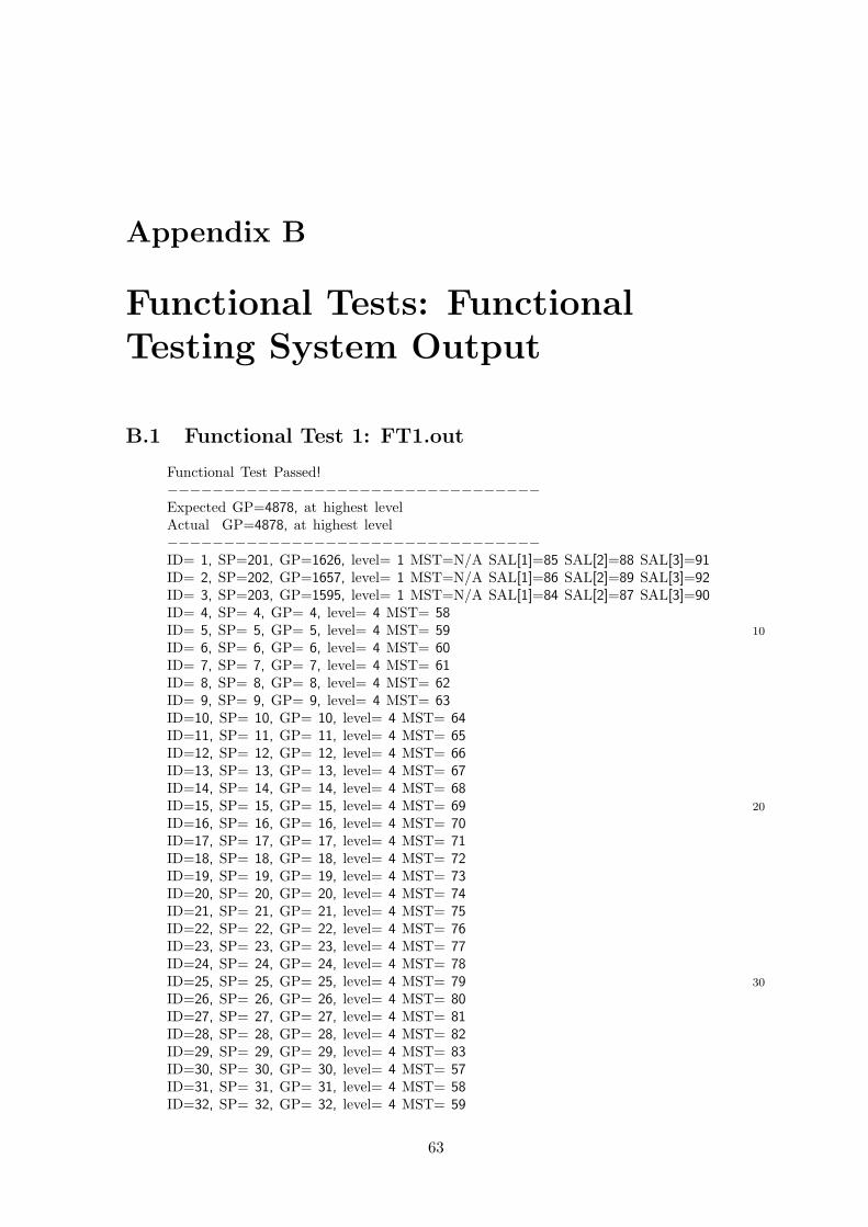
3.1.3 Functional Tests
The purpose of the Join/Leave protocol is to handle node joins and departures in the FROST net-work. The implication is that a reasonable number of nodes are required to participate in joinand/or leave activities (use cases) to test the functionality of the protocol. The functional require-ments of the Join/Leave protocol can be tested by verifying the structural relations between thenodes in the resulting FROST network against the predefined test cases. In general, the functionaltesting can be seen as comparing two networks of nodes where one is formed by the implementedJoin/Leave protocol and another is specified in the test case as it is shown in Figure3.1. Each node
8 7
2 6 3
5 4
1
8
7
2
6
3
5 4
1 ?
Test Case Actual
Figure 3.1: Functional Testing.
maintains anSALlist that specifies the master/slave relations in the network, and thus the testingproblem can be reduced to the problem of comparingSAL list of each node in the actual casewith correspondingSALlist in the test case. However, when the number of nodes in the observedsystem grows, manual specification of the test cases is not efficient because of the time neededto specify them. For the efficient test case specification an automated test case generator (TCG)has to be additionally implemented. The deployment diagram for the functional testing system isshown in Figure3.2and is explained in the following.
35
Node 1
Node 2
Node n
Functional Testing System
Test Cases
Test Suite
in 1
out 1
in out
out: SAL, GP, level in: Use Case out: Passed/Failed
TCG
in 2
in n
out 2
out n
Figure 3.2: Deployment Diagram for the Functional Testing System. TCG - Test Case Generator.
Functional Testing System Specification
To test the functional requirements of the Join/Leave protocol a number of nodes have to be ob-served by the functional testing system. The observed nodes can be defined as an-tupleof nodes,where the sequence number represents sequential events (join or leave) ordered in time:
O = (N1, N2, ..., Ni, ..., Nn), ∀1 ≤ i, j ≤ n : ∀i < j : time(i) < time(j), (3.1)
whereNi is apair: Ni = (IDi, SPi).
Each node (see Figure3.2) given an input data produces an output data, which later is used by thefunctional testing system. Input and output for all nodes are defined as follows:
Input: Then-tuple Ofrom definition3.1can be used to generate then-tuple INof join or leaveevents ordered in time:
IN = (in1, in2, ..., ini, ..., inn), ∀1 ≤ i, j ≤ n : ∀i = j : ini = e, (3.2)
wheree ∈ {join, leave} andj is an index inO.
Output: An evente at the node input triggers the corresponding behavior of the Join/Leaveprotocol:
e = leave: If node leaves the network, then no output is produced, since the node is not apart of the network anymore and that situation will be reflected by the rest of the nodesstill in the network.
e = join: In this case node joins the FROST network and by being a part of the network itprovides the join or leave services for the rest of the nodes, if requested. The outputinformation is generated by reading current state of the nodes at some constant timetand can be defined as an-tuple OUT:
OUT = (out1, out2, ..., outi, ..., outn), ∀1 ≤ i, j ≤ n : t(i) = t(j), (3.3)
whereouti is a3-tuple: outi = (SALi, GPi, leveli).
36
Expected Results
The functional testing system given the outputOUT has to verify it against the predefined test caseOUTtest. If OUT ≡ OUTtest, then the functional requirements for that particular test case aremet, otherwise there is an error in the protocol functionality. For the efficient test cases specifica-tion theTCGcomponent is introduced into the functional testing system. TheTCGcomponent hasthe same functional requirements as the implemented Join/Leave protocol, and given theO andIN specificationTCG simulates the behavior of Join/Leave protocol and produces the simulatedoutputOUTtest, which will be used as a test case for that particular setup.
3.1.4 Stress Tests
The purpose of the stress tests is to evaluate the system when stressed to its limits over a shortperiod of time. During the stress tests, as distinct from the functional tests, the observationswill be made on one particular node, which will be stressed to process continuous joining and/orleaving of nodes over a short period of time. During the stress tests the following measurementswill be taken:
CPU usage. The CPU usage will be measured usingtime utility, which is used to run programsand summarize system resource usage. The default output oftime is as follows:
real: elapsed real time in seconds.
user: total number of CPU-seconds that the process spent in user mode.
sys: total number of CPU-seconds that the process spent in kernel mode.
Percentage of the CPU usage is computed asCPU =(
user+sysreal
)· 100%.
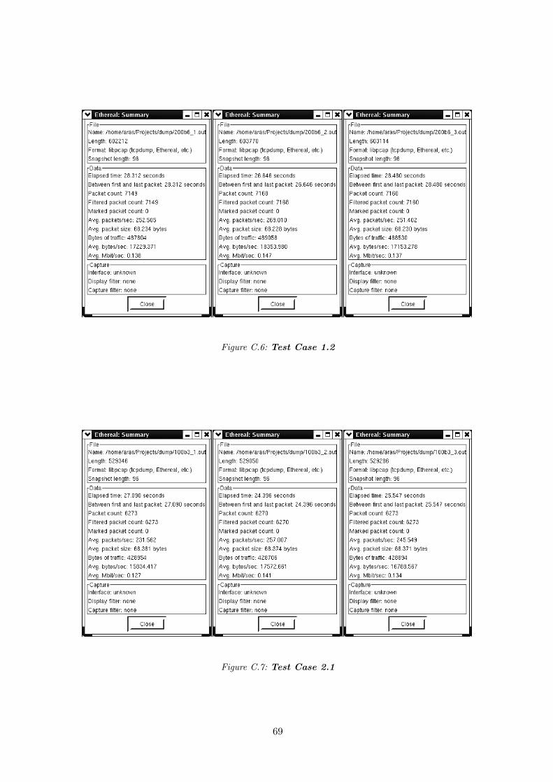
Bandwidth usage. The bandwidth usage will be measured by capturing and analyzing TCPpackets sent and received by the Join/Leave protocol. The packets will be captured usingtcpdump [7] utility and analyzed by using network protocol analyzerEthereal [8], whichis able to provide with various network usage statistics given the captured data.
Throughput. For this case, the measure of throughput is the ratio of nodes processed by theobserved node per second. Let the number of nodes processed by the observed node ben, and since the elapsed real time is given bytime utility, then throughput is computed asfollows: R = n
real ,[
nodess
].
Expected Results
The CPU usage is expected to be reasonably low, otherwise the Join/Leave protocol is not usable atall. The FROST system [1] is designated for exploiting wasted CPU-cycles on the client machinesand if the maintenance protocol such as Join/Leave protocol will utilize most of the spare CPU-cycles then only a little real work will be done.
The network bandwidth usage is expected to be the mostly consumed resource, however it shouldbe kept as small as possible. From the global point of view, a single user usually has the powerfulgaming machine, which probably waste lots of the CPU-cycles, but the connection to the Internetis not necessarily fast. Thus, if the requirements for the network bandwidth will be high, thenprobably a large number of potential CPU-cycle volunteers will not be able to use the FROSTsystem. The network bandwidth measurements will settle the approximate requirements for it.
Throughput is another important characteristic of the Join/Leave protocol. If the throughput willbe lower that the rate of the node joins and/or leaves, then the Join/Leave protocol would become
37
the bottleneck for the nodes that are waiting to join or leave the network. The estimation of therate of arrivals and departures in the FROST system is quite a challenging task. However, the rateof arrivals and departures has been explored in other P2P systems:
• The CoopNet [9] P2P system has very similar tree based network topology as the FROSTnetwork and it is also used to distribute the bandwidth usage between the peers. The study ofthe CoopNet network dynamics was made in [10]. The CoopNet system is a video streamingsystem which was evaluated using the trace of node arrivals and departures gathered atMSNBC [12] on September 11, 2001. The average rate of node arrivals and departures in the911 trace was 180 per second while the peak rate was about 1000 per second. The authorsindicate that one reason for the high rate of change may be that users were discouragedby the degradation in audio/video quality caused by the flash crowd, which caused shortlifetime of nodes (i.e. peer disconnects during the streaming session and tries to reconnectagain).
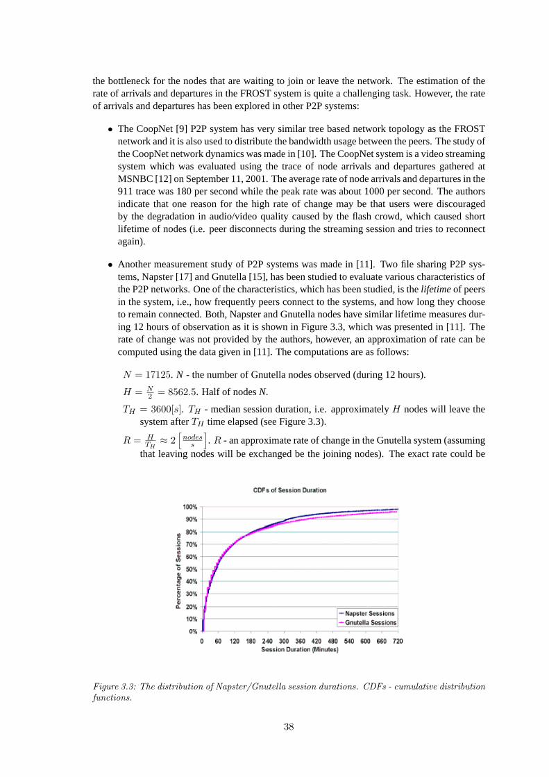
• Another measurement study of P2P systems was made in [11]. Two file sharing P2P sys-tems, Napster [17] and Gnutella [15], has been studied to evaluate various characteristics ofthe P2P networks. One of the characteristics, which has been studied, is thelifetimeof peersin the system, i.e., how frequently peers connect to the systems, and how long they chooseto remain connected. Both, Napster and Gnutella nodes have similar lifetime measures dur-ing 12 hours of observation as it is shown in Figure3.3, which was presented in [11]. Therate of change was not provided by the authors, however, an approximation of rate can becomputed using the data given in [11]. The computations are as follows:
N = 17125. N - the number of Gnutella nodes observed (during 12 hours).
H = N2 = 8562.5. Half of nodesN.
TH = 3600[s]. TH - median session duration, i.e. approximatelyH nodes will leave thesystem afterTH time elapsed (see Figure3.3).
R = HTH
≈ 2[
nodess
]. R - an approximate rate of change in the Gnutella system (assuming
that leaving nodes will be exchanged be the joining nodes). The exact rate could be
Figure 3.3: The distribution of Napster/Gnutella session durations. CDFs - cumulative distributionfunctions.
38
computed by calculating the integral, however an approximate value ofR is sufficientfor further analysis.
Both studies (CoopNet in [10] and Napster/Gnutella in [11]) gives an insight about the rate ofchange in a P2P networks. However, before evaluating the rate of change given in both studies,the human factor issues has to be considered also, i.e. what are the reasons of using one or anothersystem and what is the relation between the human factor and the rate of change? Clearly, themore the system is popular the higher is the rate of change. What makes the system being popularis another human factor issue. For instance, the thirst of knowledge during the events of the highor very high importance made the MSNBC [12] news company very popular on September 11,2001. Another example is sharing of the popular media content (music, video), which makes theP2P system a popular between the clients that are looking for entertainment. In both examples,the clients were motivated to use the system because of their own needs (thirst of knowledge,entertainment, etc.). In the FROST system, however, the users have to be motivated more tovolunteer than exploit, which probably will not make the FROST system more popular than thesystems presented above. Thus, the expectation is that the rate of change in the FROST network,with high probability, will not exceed an approximate rate of change in the Gnutella network (i.e.R ≈ 2
[nodessec
]).
3.1.5 Timing Tests
The purpose of the timing tests is to validate conformance to behavioral and performance con-straints and evaluate if the system is fast enough. During the timing tests the following measure-ments will be conducted:
Tjoin: the time required to build the FROST network from an arbitrary number of nodes.
Tleave: the time required to dismantle the FROST network consisting of an arbitrary number ofnodes.
Tjl: the time required for the half of the nodes to join the FROST network while the other half isleaving.
The timing measurements described above will be made on several distinct FROST network con-figurations using differentbaseparameters, but with constant number of nodes, to test whichconfiguration performs better (wide or narrow tree).
Another important timing measurement would be to measure the times described above with con-stantbaseparameter, but with distinct number of nodes to establish a relation between the timeand number of nodes. Then it could be possible to estimate the timing for the larger number ofnodes without performing actual test.
Expected Results
The results of the timing tests will give an insight on how fast is the system. The results willbe evaluated against the rate of change (R ≈ 2) settled in the specification of stress tests. It isexpected that Join/Leave protocol will be able to operate at the rateRactual at least equal toR(Ractual ≥ R). For instance, if 50 nodes were able to join the FROST network per 14 seconds,then the actual rate of change at which protocol is able to operate isRactual = 3.571 > R.
39
3.2 Test Description
3.2.1 Functional Tests
The purpose of the functional tests is to verify if the Join/Leave protocol operates as promisedby the functional requirements. Functional tests were conducted on the global overlay network -PlanetLab [5] (see PlanetLab specification on page34). An observation of availability was made toselect the nodes that are almost always available. 92 nodes were selected to conduct the functionaltests with Join/Leave protocol.
Functional Test 1
The purpose of this test is to verify if the protocol correctly builds the FROST network whilestressing the high level of adaptation in the network.
Test Data :
Base: Base parameterB = 3 is selected, because it will result in a reasonably complexnetwork structure with common functional characteristics for networks withB ≥ 3.The minimum value for base parameter isB = 2, however it was not selected becauseit will not reflect all the functional characteristics of the Join/Leave protocol. For ex-ample, ifB = 2 and node is leaving, then a possible choice space has a multiplicityof 1− 0..1, which means that one slave will be selected as a replacement, and at mostone slave will stay at its position. Whereas the networks withB ≥ 3 have a choicespace with multiplicity of1 − 0..∗ (one to many), i.e. if one slave is selected as areplacement, then 1 or more slaves will stay at their positions. Thus the implicationis that networks withB ≥ 3 have common functional characteristics. The complexityof network depends on the depth of the networktree. The larger is depth the morecomplex is network, and that is because join or leave inflicts updating in the networkstructure down to the bottom of the tree. Clearly, reducing the base parameter will in-
creasetreedepth for a constant number of nodes and vice versa:(
limB→∞
depth = 1)
.
In general case, for any base parameter the time complexity for join and leave opera-tions isO(log N), whereN is the number of nodes in the network.
SP: Node static performance parameter is a key parameter when building or dismantlingthe network. To stress the high level of adaptation in the network,SPvalues have tobe properly assigned to the nodes. If observed nodesO is defined as:
O = (N1, N2, ..., Ni, ..., Nn), ∀1 ≤ i, j ≤ n : ∀i < j : time(i) < time(j), (3.4)
whereNi is apair: Ni = (IDi, SPi), then:
∀1 ≤ i ≤ 3 : SPi = i + 200 : IDi = i, (3.5)
∀4 ≤ i ≤ n : SPi = IDi = i, (3.6)
wheren is the number of nodes.3.5 guarantees that nodesN1 to N3 will keep theirposition at the highest level during the tests.3.6guarantees that a joining node whoseID ≥ 13 will trigger the adaptation to the network procedure (see Fig.3.4(a)).
40
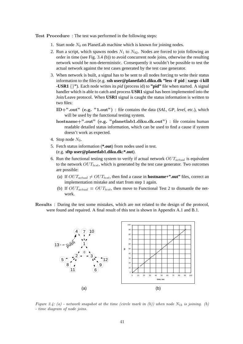
Test Procedure : The test was performed in the following steps:
1. Start nodeN0 on PlanetLab machine which is known for joining nodes.
2. Run a script, which spawns nodesN1 to N92. Nodes are forced to join following anorder in time (see Fig.3.4(b)) to avoid concurrent node joins, otherwise the resultingnetwork would be non-deterministic. Consequently it wouldn’t be possible to test theactual network against the test cases generated by the test case generator.
3. When network is built, a signal has to be sent to all nodes forcing to write their statusinformation to the files (e.g.ssh [email protected] ”less -F pid| xargs -i kill-USR1{}” ). Each node writes itspid (process id) to”pid” file when started. A signalhandler which is able to catch and processUSR1signal has been implemented into theJoin/Leave protocol. WhenUSR1signal is caught the status information is written totwo files:
ID+”.out” (e.g. ”1.out”) : file contains the data (SAL, GP, level, etc.), whichwill be used by the functional testing system.
hostname+”.out” (e.g. ”planetlab1.diku.dk.out”) : file contains humanreadable detailed status information, which can be used to find a cause if systemdoesn’t work as expected.
4. Stop nodeN0.
5. Fetch status information (*.out) from nodes used in test.(e.g.sftp [email protected]:*.out).
6. Run the functional testing system to verify if actual networkOUTactual is equivalentto the networkOUTtest, which is generated by the test case generator. Two outcomesare possible:
(a) If OUTactual 6= OUTtest, then find a cause inhostname+”.out” files, correct animplementation mistake and start from step 1 again.
(b) If OUTactual ≡ OUTtest, then move to Functional Test 2 to dismantle the net-work.
Results : During the test some mistakes, which are not related to the design of the protocol,were found and repaired. A final result of this test is shown in AppendixA.1 andB.1.
0
10
20
30
40
50
60
70
80
90
100
0 10 20 30 40 50 60 70 80 90 100
time, sec
ID
7
2
6
3 5
4
1
0
11
12
10
8 9
13 p u s h
(a) (b)
Figure 3.4: (a) - network snapshot at the time (circle mark in (b)) when node N13 is joining. (b)- time diagram of node joins.
41
Functional Test 2
The purpose of this test is to verify if the protocol correctly dismantles the FROST network whilestressing the high level of of adaptation in the network.
Test Data : For this functional test the FROST network, which was build during the FunctionalTest 1, will be used as a test data.
Test Procedure : The test was performed in the following steps:
1. Run a script, which sends the termination signal to nodesN13 to N92 following an or-der in time as it is shown in time diagram in Figure3.5(b). (e.g.ssh [email protected]”less -F pid | xargs -i kill -INT {}” ). WhenINT signal is caught a node performsvoluntary leave procedure and leaves the FROST network.
2. After nodesN13 to N92 have left , a signal has to be sent to remaining nodes forcingto write their status information to the files (e.g.ssh [email protected] ”less-F pid | xargs -i kill -USR1 {}” ). WhenUSR1signal is caught the status informationis written to two files:
ID+”.out” (e.g. ”1.out”) : file contains the data (SAL, GP, level, etc.), whichwill be used by the functional testing system.
hostname+”.out” (e.g. ”planetlab1.diku.dk.out”) : file contains humanreadable detailed status information, which can be used to find a cause if systemdoesn’t work as expected.
3. Fetch status information (*.out) from nodes used in test.(e.g.sftp [email protected]:*.out).
4. Send termination signal to the remaining nodes.
5. Run the functional testing system to verify if actual networkOUTactual is equivalentto the networkOUTtest, which is generated by the test case generator. IfOUTactual ≡OUTtest, then actual network and generated network should be the same as in Figure3.4(a).
Results : During the test some mistakes, which are not related to the design of the protocol,were found and repaired. A final result of this test is shown in AppendixA.2 andB.2.
0
10
20
30
40
50
60
70
80
90
100
0 10 20 30 40 50 60 70 80 90 100
time, sec
ID
(a) (b)
2 3
1
0
leave
85 88 91
92 89
86
84 87
90
Figure 3.5: (a) - network snapshot at the time (circle mark in (b)) when node N92 is leaving. (b)- time diagram of node leaves.
42
3.2.2 Stress Tests
Stress tests were conducted on a cluster of 7 nodes at Aalborg University (see cluster specificationon page34).
Stress Test 1
The purpose of this test is to measure a throughput - how many nodes per second an observednode can handle, CPU usage and bandwidth usage when an observed node is stressed to processan arbitrary number ofpurenode joins. Node join is calledpure if node after joining an observednode can leave without involving special processing at observed node, i.e. when joined nodedecides to leave, it just fails (all threads are canceled) and can start joining procedure again. Thisway of leaving is appropriately handled by an observed node, since it can detect failed node anddelete all information related to that node, thus other nodes can join a vacant place. The purposeof such test withpurenode joins is to measure the capabilities of an observed node (probably theone at the highest levels) which operates as a guide for the joining nodes, i.e. gives a directionwhere to join or accepts joining node.
Test Data : All 7 nodes are used for the stress test (see Fig.3.6), nodeN1 is an observed node,nodesN2 to N7 are used to concurrently perform an arbitrary number ofpurenode joins tonodeN1. Two test cases were used for testing:
Test Case 1: nodesN2 to N7 concurrently performs 50pure joins each. NodeN1 willprocess 300pure joins in total.
Test Case 2: nodesN2 to N7 concurrently performs 100pure joins each. NodeN1 willprocess 600pure joins in total.
7 2 6 3 5 4
1
Figure 3.6: Nodes used for stress test 1. N1 - observed node. N2 to N7 - nodes used to stress nodeN1.
Test Procedure : For each test case the procedure is performed in the following steps:
1. Start nodeN1 with time command to measure CPU usage (e.g.time ./observednode).
2. On the machine where nodeN1 is running, starttcpdump to capture and write to a fileall incoming and outcoming packets on a well known port used by Join/Leave protocol(e.g. tcpdump -w filename.out port 60606).
3. Run the script which spawns the nodesN2 to N7 (e.g. more hosts| xargs -ti ssh -fn”cd client; ./frostclient” , wherehostsis a file which contains hostnames of machines2 to 7 and-fn option tellsssh to go into background just before the execution ofcommand string, thensshwill return immediately after spawning a process on a remotemachine). A situation where the nodes start to operate is shown in Figure3.7 (a) andat any given moment during the execution of the test case the situation can be similarto one shown in Figure3.7(b).
43
4. Each node writes itspid (process id) tohostname+” pid” (”sister1 pid” , ”sister2 pid” ,etc.) file when started. After the test case is completed the termination signal has to besent to all nodes including the observed nodeN1 (rsh sister1 ”cd client; less -F sis-ter1 pid | xargs -ti kill -INT {}; rm -f sister1 pid” , etc.). A signal handler which cancatch and process the signals from an OS has been implemented into the Join/Leaveprotocol and it can provide with any required information about the state of the proto-col just before terminating. After this step all the nodes are terminated (see Fig.3.7(c)) and the results can be collected and analyzed (see Tables3.1and3.2).
7 2 6 3 5 4
1
join join join join join join
7 2 6
3 5 4
1
fail
join join join
fail fail
(a) (b)
7 2 6 3 5 4
1
(c)
Figure 3.7: (a) - network snapshot when the stress test 1 was started; (b) - network snapshot duringthe execution of the stress test 1; (c) network snapshot when the stress test 1 was completed.
Test Results :
B = 6 Time CPU usage# time, s ∆time, s nodes/s user, s sys, s CPU, % ∆CPU#, %
Table 3.1: Measurements of pure join rate (nodes/s) and CPU usage at node N1. # - is the numberof joins processed by node N1. B - is the base of the FROST architecture.
B = 6 Bandwidth usage# ∆time, s kbytes of traffic traffic, Mbits/s ∆traffic#, Mbits/s
569.19 2.10300 2.17 568.62 2.20 2.15
569.64 2.151133.44 2.24
600 4.25 1139.42 2.23 2.241138.24 2.25
∆ traffic, Mbits/s : 2.19
Table 3.2: Measurements of bandwidth usage at node N1. # - is the number of pure node joinsprocessed by node N1. B - is the base of the FROST architecture.
44
Stress Test 2
The purpose of this test is to measure a throughput - how many nodes per second an observednode can handle, CPU usage and bandwidth usage when an observed node is stressed to processan arbitrary number of concurrent node joins and voluntary leaves.
Test Data : All 7 nodes are used for the stress test (see Fig.3.6), nodeN1 is an observed node,nodesN2 toN7 are used to concurrently perform an arbitrary number of node joins followedby voluntary leaves. Two test cases were used for testing:
Test Case 1: nodesN2 to N7 concurrently performs 50 joins and 50 voluntary leaveseach. NodeN1 will process 300 joins and 300 voluntary leaves in total.
Test Case 2: nodesN2 to N7 concurrently performs 100 joins and 100 voluntary leaveseach. NodeN1 will process 600 and 600 voluntary leaves in total.
Test Procedure : The test procedure is the same as presented for the stress test 1 on page43,except that nodes are not failing after each join but leaving according to voluntary leaveprocedure. The results are shown in Tables3.3and3.4
Test Results :
B = 6 Time CPU usagejoin#/leave# time, s ∆time, s nodes/s user, s sys, s CPU, % ∆CPU#, %
Table 3.3: Measurements of rate (nodes/s) and CPU usage at node N1. join# - is the number ofjoins processed by node N1. leave# - is the number of voluntary leave processed by node N1. B -is the base of the FROST architecture.
B = 6 Bandwidth usagejoin#/leave# ∆time, s kbytes of traffic traffic, Mbits/s ∆traffic#, Mbits/s
729.05 0.94300/300 6.42 725.85 0.95 0.93
725.44 0.891427.23 1.04
600/600 12.31 1454.80 0.94 0.971460.90 0.92
∆ traffic, Mbits/s : 0.95
Table 3.4: Measurements of bandwidth usage at node N1. join# - is the number of joins processedby node N1. leave# - is the number of voluntary leave processed by node N1. B - is the base of theFROST architecture.
45
Stress Test 3
The first two stress tests gives a result where the rate of change is noticeably higher than expected(Ractual ≈ 100 À Rexpected ≈ 2), whereas bandwidth usage is very high (≈ 1 Mbit/s), whichimplies that the bandwidth is the most consumed resource as expected. The purpose of this test isto measure bandwidth usage when an observed node is stressed to process an arbitrary number ofnode joins and voluntary leaves at the rate of change close toRexpected.
Test Data : All 7 nodes are used for the stress test (see Fig.3.6), nodeN1 is an observednode. To reduce the rate of change in an observed network of nodes only one node (N7) willperform an arbitrary number of node joins followed by voluntary leaves. NodesN2 to N6
joins the network once and participates in the network activities. The following test caseswere used for testing:
Test Case 1: FROST architecture baseB = 6. Two different scenarios were tested:
1. NodeN7 performs 100 joins and 100 voluntary leaves.
2. NodeN7 performs 200 joins and 200 voluntary leaves.
Test Case 2: FROST architecture baseB = 3. Two different scenarios were tested:
1. NodeN7 performs 100 joins and 100 voluntary leaves.
2. NodeN7 performs 200 joins and 200 voluntary leaves.
Test Case 3: FROST architecture baseB = 2. Two different scenarios were tested:
1. NodeN7 performs 100 joins and 100 voluntary leaves.
2. NodeN7 performs 200 joins and 200 voluntary leaves.
Test Procedure : The test procedure is the same as presented for the stress test 1 on page43.The snapshots of the network during each test case is shown in Table3.5. The results areshown in Tables3.6, 3.7, 3.8, 3.9, 3.10and3.11.
Test Case 1 Test Case 2 Test Case 3
7
2 6 3 5 4
1 join 7
2
6
3
5 4
1 join 7
2
6
3
5
4
1 join
7 2 6 3 5 4
1 l e a v e
l e a v e
7
2
6
3
5
4
1
l e a v e
7
2
6
3 5 4
1
Table 3.5: Test cases for stress test 3. N1 - observed node. N2 to N6 - nodes are participants inthe network. N7 is used to stress node N1.
46
Test Results :
B = 6 Time CPU usagejoin#/leave# time, s ∆time, s nodes/s user, s sys, s CPU, % ∆CPU#, %
Table 3.6: Test Case 1. Measurements of rate (nodes/s) and CPU usage at node N1. join# - isthe number of joins processed by node N1. leave# - is the number of voluntary leave processed bynode N1.
B = 6 Bandwidth usagejoin#/leave# ∆time, s kbytes of traffic traffic, kbits/s ∆traffic#, kbits/s
237.43 91.14100/100 18.73 238.53 114.69 108.20
238.27 118.78476.37 141.31
200/200 27.81 477.60 150.53 144.04477.08 140.29
∆ traffic, kbits/s : 126.12
Table 3.7: Test Case 1. Measurements of bandwidth usage at node N1. join# - is the number ofjoins processed by node N1. leave# - is the number of voluntary leave processed by node N1.
B = 3 Time CPU usagejoin#/leave# time, s ∆time, s nodes/s user, s sys, s CPU, % ∆CPU#, %
Table 3.8: Test Case 2. Measurements of rate (nodes/s) and CPU usage at node N1. join# - isthe number of joins processed by node N1. leave# - is the number of voluntary leave processed bynode N1.
47
B = 3 Bandwidth usagejoin#/leave# ∆time, s kbytes of traffic traffic, kbits/s ∆traffic#, kbits/s
418.90 130.05100/100 25.68 418.66 144.38 137.22
418.84 137.22849.48 143.36
200/200 44.44 851.49 171.01 161.79852.25 171.01
∆ traffic, kbits/s : 149.50
Table 3.9: Test Case 2. Measurements of bandwidth usage at node N1. join# - is the number ofjoins processed by node N1. leave# - is the number of voluntary leave processed by node N1.
B = 2 Time CPU usagejoin#/leave# time, s ∆time, s nodes/s user, s sys, s CPU, % ∆CPU#, %
Table 3.10: Test Case 3. Measurements of rate (nodes/s) and CPU usage at node N1. join# - isthe number of joins processed by node N1. leave# - is the number of voluntary leave processed bynode N1.
B = 2 Bandwidth usagejoin#/leave# ∆time, s kbytes of traffic traffic, kbits/s ∆traffic#, kbits/s
418.51 131.07100/100 24.17 417.38 163.84 144.38
403.11 138.24848.36 169.98
200/200 46.16 847.42 172.03 160.43921.59 139.26
∆ traffic, kbits/s : 152.41
Table 3.11: Test Case 3. Measurements of bandwidth usage at node N1. join# - is the numberof joins processed by node N1. leave# - is the number of voluntary leave processed by node N1.
48
3.2.3 Timing Tests
The purpose of timing tests is to evaluate if the system is fast enough, while assuring that itperforms according functional requirements.
Timing Test 1
The purpose of this test is to measure the timeTjoin required to build the FROST network from anarbitrary number of nodes and the timeTleave required to dismantle the FROST network consistingof an arbitrary number of nodes.
The Join/Leave protocol implementation has been modified to automatically gather the followingtime statistics:
1. start, endanddurationof join procedure. Data is gathered in the following steps:
Test Case 1: Build the network using 40 randomly selected nodes deployed at variouslocations in the world. BaseB = 3.
Test Case 2: Use the network from Test Case 1 to dismantle it.
Test Procedure. Test Case 1: The test was performed in the following steps:
1. StartN0
2. Spawn all 40 nodes in parallel to stress concurrent joins. (e.g.ssh -fn [email protected]”cd client; ./frostclient” & ).
3. When the network is built, collect the results (e.g.sftp [email protected]:*.out).See Fig.3.8(a) for results.
4. StopN0
49
Test Procedure. Test Case 2: The test was performed in the following steps:
1. Signal the nodes to start leaving the network. (e.g.ssh [email protected]”less -F pid | xargs -i kill -INT {} &” )
2. When network is dismantled, collect the results. (e.g.sftp [email protected]:*.out).See Fig.3.8(b) for results.
Test Results :
Test Case 1: The network was built in about 20 seconds -Tjoin ≈ 20 [sec] and the join
rate isRjoin ≈ 2[
nodessec
]. Two nodes (N17 andN30) have failed to join, and that is
because the discovery serverN0 for unknown reasons refused to establish a connectionwith them.
Test Case 2: The network was dismantled in about 8 seconds -Tleave ≈ 8 [sec] and the
leave rate isRleave ≈ 5[
nodessec
].
This test was repeated several times and similar failures occurred, when one or few nodeswere not able to contact nodeN0. Also in some cases few unexpected connection losseswere experienced while a node was performing a join or leave procedure causing somenodes to deadlock.
Because of different bandwidth load on PlanetLab at different day time the measured timesTjoin andTleave may change, because of delays in the network.
Figure 3.8: (a) - time diagram of joins. (b) - time diagram of departures. A horizontal line indiagram represents time duration of join or leave operation. Error of measurement: ± 1 second.
50
Timing Test 2
The purpose of this test is to measure the timesTjoin andTleave as described in Timing Test 1, butwith distinct FROST network configurations using differentbaseparameters and with constantnumber of nodes, to test which configuration performs better (wide or narrow tree). Also animportant timing measurement would be to measure the times described above with constantbaseparameter, but with distinct number of nodes to establish a relation between the time and numberof nodes. Then it could be possible to estimate the timing for the larger number of nodes withoutperforming actual test.
Test Data: The test data is summarized in Table3.12.
Base# 3 6 920 Test Case 1 Test Case 4 Test Case 740 Test Case 2 Test Case 5 Test Case 860 Test Case 3 Test Case 6 Test Case 9
Table 3.12: Timing Test 2. Test data. # - is the number of nodes used in a test case.
Test Procedure: For each test case the timesTjoin andTleave will be measured following theprocedure described in Timing Test 1.
Test Results : The results are summarized in Table3.13and Figure3.9.
Base3 6 9
# Tjoin Tleave Tjoin Tleave Tjoin Tleave
20 9 3 5 1 6 240 20 8 12 5 13 560 34 10 22 9 20 9
Table 3.13: Timing Test 2. Test results. # - is the number of nodes used in a test case. Timingresults are presented in seconds. Error of measurement: ± 1 second.
Timing Test 3
The purpose of this test is to measure the timeTjl - required for the half of the nodes to join theFROST network while the other half is leaving.
Test Data: 40 nodes, which were used in Timing Test 1, will be used to build the network andleave it while other 40 nodes will join the network.
Test Procedure: The test was performed in the following steps:
1. Build the network of 40 nodes as described in Timing Test 1, Test Case 1.
2. When built, dismantle the network as described in Timing Test 1, Test Case 2 and atthe same time start to build the network from other 40 nodes as described in TimingTest 1, Test Case 1.
3. When network is built, collect the results and terminate all nodes.
51
(a)
B = 3
0
10
20
30
40
50
60
70
0 5 10 15 20 25 30 35 40 time, sec
#
Join
Leave
B = 6
0
10
20
30
40
50
60
70
0 5 10 15 20 25 30 35 40
time, sec
#
Join
Leave
B = 9
0
10
20
30
40
50
60
70
0 5 10 15 20 25 30 35 40
time, sec
#
Join
Leave
# = 20
0 1 2 3 4 5 6 7 8 9
10
0 5 10 15 20 25 30 35 40
time, sec
B
Join
Leave
# = 40
0 1 2 3 4 5 6 7 8 9
10
0 5 10 15 20 25 30 35 40
time, sec B
Join
Leave
# = 60
0 1 2 3 4 5 6 7 8 9
10
0 5 10 15 20 25 30 35 40
time, sec
B
Join
Leave
(b)
Figure 3.9: (a) - the results of the Timing Test 2 with the constant base parameter. (b) - the resultsof the Timing Test 2 with the constant number of nodes. # - is the number of nodes used in thetest.
Test Results : The test was not able to complete, because of unexpected connection lossesbetween the nodes, causing some nodes to deadlock. Fault tolerance was not implementedin the protocol assuming that all nodes will be reliable and no connection losses will happen.The assumption was made with intent to primarily test and measure the Join/Leave protocolperformance with reliable nodes and then concentrate on the fault tolerance.
Some deadlock situations that happened during the tests are listed below:
• When master node grants an asking node a permission to leave or push, master has towait until the replacement will connect. If node, which was chosen as a replacementfails or node, which was granted for an operation fails then master node will wait fora replacement forever.
• During leave or push operation a number of nodes are involved in exchanging data andinstructions. If, however, at least one connection is lost then some nodes will wait forthe events that will never happen, causing the system to deadlock.
52
3.3 Test Results Analysis
3.3.1 Functional Tests
The main corollary of the functional test results is that the Join/Leave protocol correctly builds anddismantles the network, unless the connection losses during the join or leave operation has hap-pened. The results that are presented in appendixA.1 andA.2 where collected when no connectionlosses occurred and no nodes have failed. However, there were some cases when connection fail-ures occurred and system deadlocked.
3.3.2 Stress Tests
CPU usage: As expected the CPU usage is reasonably low -CPU ≈ 15%, even when stressedto operate at rateR ≈ 140
[nodessec
](see Table3.1). To evaluate and measure the CPU and
bandwidth usage at lower join and leave rates a special test was conducted. Three test caseswere used in testing, and when operating at rateR ≈ 10 the CPU usage isCPU ≈ 1% andthat is a desired result. (see Tables3.6, 3.8and3.10).
Bandwidth usage: As expected the bandwidth usage is the most consumed resource. Whenstressed to operate at rateR ≈ 120 the bandwidth consumption was quite large and unsuit-able (traffic≈ 1.5
[Mbitsec
], see Tables3.2and3.4) for Internet wide usage. However, when
operating at rateR ≈ 10 the bandwidth usage istraffic≈ 150[
kbitsec
](see Tables3.7, 3.9and
3.11), which is quite normal if having fast (e.g.≥ 256[
kbitsec
]) Internet connection.
Throughput: The maximum throughput which could be expected under certain conditions isR ≈ 140. When stressed there were more free resources available: about85% of CPUand about97% of bandwidth resources were unused, but they were not consumed. Anexplanation of it could be in the internals of the protocol itself, i.e. mutual exclusion devices,barriers, etc.
The main corollary of the stress test results is that the Join/Leave protocol should be able toefficiently operate at the rate of change (R ≈ 2), which was previously settled in the analysisof the Gnutella system. When operating at rateR ≈ 2, the expected resource usage could be asfollows:
CPU usage: CPU ≈ 1% (for CPU’s faster than1Ghz).
Bandwidth usage: traffic≈ 30[
kbitsec
].
3.3.3 Timing Tests
Running the Join/Leave protocol in the realistic environment such as PlanetLab confirms that thefault tolerance is a critical part in the FROST system and must be implemented if it is planned touse the system Internet wide, where the machines are not reliable.
The results of timing tests indicate that the rate of change isR ≈ 3.5 and according the expecta-tions the Join/Leave protocol satisfies the timing constraints.
Also the results of testing the protocol with different configuration setup indicate that the baseparameter could be adjusted for better performance in the system (see Figure3.9(b)). The resultsin Figure3.9(a) indicate that the time required for building and dismantling the network increasesalmost linearly when the number of nodes increases.
53
Chapter 4
Conclusion
The two main goals of this project were:
1. To implement the prototype of the Join/Leave protocol, whose system architecture and con-cepts were described in [2]. The purpose of the Join/Leave protocol is to handle the nodejoins and departures in the FROST network. In general the Join/Leave protocol can bedivided into two parts based on the function it should perform:
Join: The Join/Leave protocol must assure that a node which joins the network will beorganized in the hierarchy according to its static performance measure -SP.
Leave: When nodes leave the network (voluntarily or by failing) the Join/Leave protocolhas to assure the integrity of the communication architecture by appropriately rear-ranging the related nodes in the network.
2. To conduct a proof-of-concept evaluation of the Join/Leave protocol by performing systemtesting, which focuses on the complete system, its functional and non-functional require-ments, and its target environment. The following system tests were conducted:
Functional testing. Functional testing, also called requirements testing, tests if the sys-tem perform as promised by the requirements specification.
Performance testing. Performance testing is used to test if the non-functional require-ments are met. Two types of performance tests were conducted:
Stress tests: The purpose of the stress tests is to evaluate the system when stressedto its limits over a short period of time.
Timing tests: The purpose of the timing tests is to validate conformance to behav-ioral and performance constraints and evaluate if the system is fast enough.
4.1 Implementation
Some corrections have been made to the design [2] of the Join/Leave protocol before implementingit. Two main corrections were made:
1. The static node performanceSP has been derived from available network bandwidth re-sources disregarding the speed of CPU and the size of the main memory.
2. Joining and adaptation to the network procedure has been optimized.
54
The Join/Leave protocol has been decomposed and implemented as four components:
1. Model Component. A part of a system that implements a model of the Join/Leave protocol.
2. Function Component. A part of a system that implements functional requirements of theJoin/Leave protocol.
3. System Interface Component. A part of a system implementing the interaction with othersystems.
4. User Interface Component. A part of a system implementing the interaction with users.
4.2 Testing
The following system tests were conducted:
Functional testing. The results of functional tests indicate that the Join/Leave protocol cor-rectly builds and dismantles the network, unless the connection losses during the join orleave operation has happened.
Stress tests. The results of stress tests indicate that the Join/Leave protocol should be able toefficientlyoperate at the rate of change (R ≈ 2), which was previously settled in the analysisof the Gnutella system. When operating at rateR ≈ 2, the expected resource usage is asfollows:
CPU usage: CPU ≈ 1% (for CPU’s faster than1Ghz).
Bandwidth usage: traffic≈ 30[
kbitsec
].
Timing tests. The results of timing tests (R ≈ 3.5) indicate that the Join/Leave protocol sat-isfies the timing constraints, unless the connection losses during the join or leave operationhas happened. Also the results of testing the protocol with different configuration setup in-dicate that the base parameter could be adjusted for better performance in the system (seeFigure3.9(b)). The results in Figure3.9(a) indicate that the time required for building anddismantling the network increases almost linearly when the number of nodes increases.
4.3 Further Work
The parts of the system that were left out will be summarized in this section.
Fault tolerance. Fault tolerance was not designed in [2] and it was not planned to implementit in this work. The intent was to primarily test the Join/Leave protocol assuming that allnodes are reliable and then focus on fault tolerance. Running the Join/Leave protocol in therealistic environment such as PlanetLab confirms that the fault tolerance is a critical partin the FROST system and must be implemented if it is planned to use the system Internetwide, where the machines are not reliable. It is expected that fault tolerance solution willintroduce an additional overhead to the system and therefore the system testing has to beperformed again to evaluate if the protocol still satisfies the functional and non-functionalrequirements.
Interoperability. To fulfill its purpose, the Join/Leave protocol has to be incorporated to theFROST system [1].
55
Security. The maintenance protocols are especially susceptive to the DoS (Denial of Service)attacks. Since the Join/Leave protocol is intended to operate Internet wide there is a highrisk of such attacks.
Portability. The protocol should be able to operate on various technical platforms to increasethe number of potential users of the FROST system [1]. The current implementation of theJoin/Leave protocol is based on Linux OS.
56
Bibliography
[1] Michael Platz Glibstrup and Lars Kringelbach. FROST - A Distributed Heteroge-neous Calculation Platform. Student report, Aalborg University - Department ofComputer Science, January 2002.
[2] Li Ming and Arunas Vrubliauskas. Scalability of the FROST System. Student re-port, Aalborg University - Department of Computer Science, January 2003.
[3] Lars Mathiasen, Andreas Munk-Madsen, Peter Axel Nielsen and Jan Stage. ObjectOriented Analysis & Design. Forlaget MARKO. ISBN 87-7751-150-6. 1st edition,2000.
[4] David Liben-Nowell, Hari Balakrishnan, and David Karger. Analysis of the Evolu-tion of Peer-to-Peer Systems. ACM Conf. on Principles of Distributed Computing(PODC), Monterey, CA, July 2002.
[5] PlanetLab - An open testbed for developing, deploying, and accessing planetary-scale services. http://www.planet-lab.org
[6] SETI@home - The Search for Extraterrestrial Intelligence.http://setiathome.ssl.berkeley.edu/
[10] Venkata N. Padmanabhan, Helen J. Wang, Philip A. Chou and Kunwadee Sripanid-kulchai. Distributing Streaming Media Content Using Cooperative Networking.Microsoft Research Technical Report, MSR-TR-2002-37, April 2002.
[11] S. Saroiu, P. K. Gummadi, and S. D. Gribble. A measurement study of peer-to-peerfile sharing systems. In Proceedings of MMCN, 2002.