Publications of the DLR elib elib elib This is the author’s copy of the publication as archived with the DLR’s electronic library at http://elib.dlr.de. Please consult the original publication for citation. Joint-Level Control of the DLR Lightweight Robot SARA Maged Iskandar, Christian Ott, Oliver Eiberger, Manuel Keppler, Alin Albu-Sch¨ affer, and Alexander Dietrich Copyright Notice c 2020 IEEE. Personal use of this material is permitted. However, permission to reprint/republish this material for advertising or promotional purposes or for creating new collective works for resale or redistribution to servers or lists, or to reuse any copyrighted component of this work in other works must be obtained from the IEEE. Citation Notice @ARTICLE{Iskandar2020_joint, author = {Maged Iskandar, Christian Ott, Oliver Eiberger, Manuel Keppler, Alin Albu-Sch\"affer, and Alexander Dietrich}, title = {Joint-Level Control of the DLR Lightweight Robot SARA}, booktitle = {Proc. of the 2020 IEEE/RSJ International Conference on Intelligent Robots and Systems (IROS)} year = {2020}, organization = {IEEE}, pages = {8903-8910}, month = {October}, }
Transcript
Publications of the DLR elibelibelib
This is the author’s copy of the publication as archived with the DLR’s electronic library at http://elib.dlr.de. Pleaseconsult the original publication for citation.
Joint-Level Control of the DLR Lightweight Robot SARAMaged Iskandar, Christian Ott, Oliver Eiberger, Manuel Keppler, Alin Albu-Schaffer, and AlexanderDietrich
Copyright Noticec 2020 IEEE. Personal use of this material is permitted. However, permission to reprint/republish this material for
advertising or promotional purposes or for creating new collective works for resale or redistribution to servers or lists,or to reuse any copyrighted component of this work in other works must be obtained from the IEEE.
Citation Notice@ARTICLE{Iskandar2020_joint,
author = {Maged Iskandar, Christian Ott, Oliver Eiberger, Manuel Keppler, Alin Albu-Sch\"affer, and Alexander Dietrich},
title = {Joint-Level Control of the DLR Lightweight Robot SARA},
booktitle = {Proc. of the 2020 IEEE/RSJ International Conference on Intelligent Robots and Systems (IROS)}
year = {2020},
organization = {IEEE},
pages = {8903-8910},
month = {October},
}
Joint-Level Control of the DLR Lightweight Robot SARA
Maged Iskandar, Christian Ott, Oliver Eiberger, Manuel Keppler, Alin Albu-Schaffer, and Alexander Dietrich
Abstract— Lightweight robots are known to be intrinsicallyelastic in their joints. The established classical approaches tocontrol such systems are mostly based on motor-side coordi-nates since the joints are comparatively stiff. However, thatinevitably introduces errors in the coordinates that actuallymatter: the ones on the link side. Here we present a newjoint-torque controller that uses feedback of the link-sidepositions. Passivity during interaction with the environment isformally shown as well as asymptotic stability of the desiredequilibrium in the regulation case. The performance of thecontrol approach is experimentally validated on DLR’s newgeneration of lightweight robots, namely the SARA robot, whichenables this step from motor-side-based to link-sided-basedcontrol due to sensors with higher resolution and improvedsampling rate.
I. INTRODUCTION
Nowadays, the growing interest in lightweight collabora-tive robots becomes more evident in many applications. Achallenge that is inherent to these modern systems is thejoint flexibility. The main source of flexibility is due tothe presence of a flexible reduction element (e. g. Harmonicdrive gears or other transmission units). These transmis-sion elements have the advantage of high reduction ratioswhile enabling compact in-line design. However, the weaklydamped elasticity results in an unwanted oscillatory behaviorof the output (link position). In order to achieve a high perfor-mance on these systems, it is crucial to include this parasiticelasticity in the control design. If not handled properly, onefaces vibration problems during free motion and possiblychattering/instability in scenarios when the robot interactswith the environment [1]. In order to enable safe interactionwith the environment and in particular with humans, theselightweight robots are often equipped with torque sensorsin addition to motor position sensors [2], [3]. Compared topure motor position sensing, the additional integration oftorque sensors provides various advantages from the controlpoint of view. The combined feedback of the motor positionand joint torque measurements in a feedback loop allows toimprove active vibration damping and to achieve a desiredimpedance behavior during physical human-robot interaction[4], [2]. In [5] this combined feedback is used to solvethe position, torque, and impedance control problem. It isimportant to remark that the additional integration of torquesensors introduces another source of elasticity. However, thiseffect can be lumped together with the flexibility introducedby the transmission gear into concentrated flexibility for eachjoint.
The link-side regulation problem for flexible joint robotshas been treated in [6]–[9]. All of these controllers consider
All authors are with the DLR - German Aerospace Center, Roboticsand Mechatronics Center, Institute of Robotics and Mechatronics, Wessling,Germany. Email: [email protected]
Fig. 1: The next generation of DLR lightweight robots: SARA (SafeAutonomous Robotic Assistant)
only feedback of control-input-collocated variables. There-fore, the damping performance is lower compared to theregulation controllers reported in [10], [11], which employfeedback of control-input-noncollocated variables. However,no stability analysis of the closed-loop dynamics has beenprovided so far.
The proposed approach follows the idea of a changeof coordinates as introduced in [12]. This control conceptpreserves the intrinsic structure of robots with elastic jointswhile achieving a desired link-side motion tracking behavior.An extension [13] of this concept allows to implement atorque interface for the compliant robots which can be em-ployed to implement a desired Cartesian impedance behaviorat the TCP. In this work, we modify this concept to tailorit to the special characteristics of lightweight robots withadditional joint torque sensors. The object of this work isto derive a torque-based controller that effectively dampensjoint vibrations and provides a link-side torque interfacewhile exploiting the full set of available measurementsincluding joint torques.
We use the state vector (q, τ , q, τ ) for control throughoutthe paper. It contains the link positions q and the joint torquesτ , both directly measured by sensors, as well as their firstderivatives q and τ , which are computed numerically. Let usmotivate this choice of state vector. Obviously, in absenceof a torque sensor, the state vector (q,θ, q, θ), as in thework [12], can be used instead.1 However, accurate valuesof the joint torques are crucial for good control performance.Model-based joint torque estimation is potentially insuffi-
1These two state vectors are related in a linear fashion.
cient for robots with relatively high joint stiffness valuesas present in lightweight robots. Note that the resolution ofthe torque signal is directly related to uncertainties in thejoint stiffness estimation or joint deflection measurement. Inrobots where elasticity is deliberately introduced into thejoints in order to increase the interaction performance andsafety, the joint stiffness is usually of magnitudes lower thanin lightweight robots. In this case, it is sufficient to relyon feedback of the state (q,θ, q, θ) including joint torquesignals.
The paper is organized as follows. In Section II weintroduce the system model to be used throughout this workand provide an overview of the standard control approachesfor this type of system. The proposed method and the generaldesign idea are presented in Section III. In Section IV, aformal passivity and stability analysis is provided. Experi-mental validations of the approach are shown and discussedin Section V. Finally, the conclusion in Section VI closesthe paper.
II. BACKGROUND
The equations of motion of a flexible-joint robot requiretwice the number of generalized coordinates compared tothe rigid-body case. Correspondingly, different coordinatesare associated with the motor and the link side, respectively,see Fig. 2. The dynamics of a robot with elastic joints basedon the standard model [14] can be written as
M(q)q +C(q, q)q + g(q) =K(θ − q) + τext , (1)
Bθ +K(θ − q) = τm . (2)
Herein, q ∈ Rn represents the vector of the n link-sidepositions and θ ∈ Rn describes the motor positions.2 Letτ =K(θ − q) be the elastic torque which is transmit-ted between motor and link, with the positive definitejoint stiffness K � 0. Gravitational effects are repre-sented by g(q) ∈ Rn, and the link-side inertia and Corio-lis/centrifugal matrices are defined by M(q) ∈ Rn×n andC(q, q) ∈ Rn×n, respectively. The external torque is de-scribed by τext. The motor inertia is given byB ∈ Rn×n andaccelerated by the motor torque τm.3 The above-mentionedmodel is considered to be simplified as it was proposedin [14] in the sense that it assumes that the kinetic energyof each motor is only due to its own rotation. Two addi-tional common assumptions have been made with respect to(1)–(2):
Assumption 1: The joint elasticity can be modeled as alinear torsional spring.
Assumption 2: The flexibility is concentrated at the robotjoints while the links are rigid.
Probably the most common way for torque-regulationcontrol (1)–(2) is to utilize a classical PD controller [1], [5]
τm = τd +KT (τd − τ )−KS τ . (3)
2The motor position is reflected with the reduction gear ratio so that ithas the same dynamic range as the link position, and the model (1)–(2) isconsequently independent of the gear ratio.
3The motor is modeled as an ideal torque source neglecting the electricaldynamics.
Link position sensor
Torquesensor DLR-BLDC
motor
Harmonic drivegear unit
Motor position sensor
Robot link
Motorsafety brake
Fig. 2: The DLR SARA robot, an exploded view of a single jointdesign, and the simplified flexible joint model.
The desired joint torque τd is fed forward and the (measured)joint torque τ and its time derivative τ are used in thefeedback loop incorporating the corresponding gains KT ,KS .4 From a physical point of view, (3) can be intuitivelyinterpreted as an active reduction of the motor inertia fromB to the desired valueBd when choosingKT = BB−1
d −I ,as shown in [5], [9]. The control action (3) can be combinedwith a motor position PD regulation controller to form theso-called full-state feedback controller
τd = −Kθθ −Dθθ + g(θ) , (4)
where θ = θ − θd is the motor position error, and θd is thedesired, constant motor position. Furthermore, Kθ,Dθ � 0represent the controller stiffness and damping on the motorside. To implement a desired link-side behavior with (4), θdcan be statically computed model-based on the desired link-side position qd utilizing information on the joint elasticityand gravitational effects. However, the performance of thiscontroller is highly dependent on uncertainties in these quan-tities. In the model (1)-(2), dissipative friction effects can beincluded in different ways. The most dominant component inSARA is the motor-side friction due to the harmonic drivegear. However, motor-side friction is considerably reducedas a result of the motor inertia shaping as described laterin Sect. III-C. Further friction effects can be addressedby means of model-based friction compensation techniques[15]–[17] and/or the use of motor disturbance observers [18].Furthermore, structural damping can be considered as theresult of a viscoelastic joint model which can be, in turn,reflected as a compensation term in the control law [5].Nevertheless, the initial design concept in this paper focuseson the effects of joint flexibility, and therefore, friction effectsare not explicitly considered in the following analysis.
III. METHODS
The aim of this work is to achieve the same performancein terms of end-effector motion accuracy as in pure rigid-
4The term τ is usually derived numerically, based on τ .
body robots where the joint actuator is acting (applying theactuation torque) directly on the link coordinates q. Themain challenge is described by the fact that the motor torque(control input) is non-collocated with the link coordinates(output).
A. Link-side torque interface and motor inertia shaping
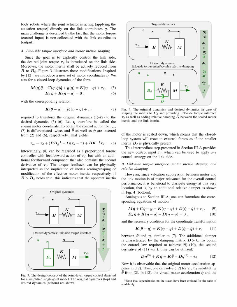
Since the goal is to explicitly control the link side,the desired joint torque τd is introduced on the link side.Moreover, the motor inertia shall be actively reduced fromB to Bd. Figure 3 illustrates these modifications. Inspiredby [12], we introduce a new set of motor coordinates η. Weaim for a closed-loop dynamics of the form
required to transform the original dynamics (1)–(2) to thedesired dynamics (5)–(6). Let η therefore be called thevirtual motor coordinate. To obtain the control action for τm,(7) is differentiated twice, and θ as well as η are insertedfrom (2) and (6), respectively. That yields
τm = τd + (BB−1d − I)(τd − τ ) +BK−1τd . (8)
Interestingly, (8) can be regarded as a proportional torquecontroller with feedforward action of τd, but with an addi-tional feedforward component that also contains the secondderivative of τd. The torque feedback can be physicallyinterpreted as the implication of inertia scaling/shaping ormodification of the effective motor inertia, respectively. IfB > Bd holds true, this indicates that the apparent inertia
Desired dynamics: link-side torque interface
Original dynamics
Fig. 3: The design concept of the joint-level torque control depictedfor a simplified single-joint model. The original dynamics (top) anddesired dynamics (bottom) are shown.
Desired dynamics: link-side torque interface plus relative damping
Original dynamics
Fig. 4: The original dynamics and desired dynamics in case ofshaping the inertia to Bd and providing link-side torque interfaceτd as well as adding relative damping D between the scaled motorinertia and the link inertia.
of the motor is scaled down, which means that the closed-loop system will react to external forces as if the smallerinertia Bd is physically present.
This intermediate step presented in Section III-A providesthe new control input τd, which can be used to apply anycontrol strategy on the link side.
B. Link-side torque interface, motor inertia shaping, andrelative damping
However, since vibration suppression between motor andthe link motion is of major relevance for the overall controlperformance, it is beneficial to dissipate energy at this verylocation, that is, by an additional relative damper as shownin Fig. 4 (bottom).
Analogous to Section III-A, one can formulate the corre-sponding equations of motion 5
and the necessary condition for the coordinate transformation
K(θ − q) =K(η − q) +D(η − q) + τd (11)
between θ and η, similar to (7). The additional damperis characterized by the damping matrix D � 0. To obtainthe control law required to achieve (9)–(10), the secondderivative of (11) w. r. t. time can be utilized:
Dη(3) +Kη =Kθ +Dq(3) − τd (12)
Now it is observable that the original motor acceleration ap-pears in (12). Thus, one can solve (12) for τm by substitutingθ from (2). In (12), the virtual motor acceleration η and the
5Note that dependencies on the states have been omitted for the sake ofreadability.
jerk η(3)6 can be straightforwardly obtained from (10) andits time derivative, respectively. That finally delivers
τm =BK−1DB−1d (−K(η − q)−D(η − q))
+Bη +BK−1(τd −Dq(3)) +K(θ − q) .(13)
Substituting η from (10) and η from (11) and solving (11)for η, one can formulate the control law in a more compactform as
Equation (14) implements the desired dynamics (9)–(10) andleads to damping of the torque dynamics in a controllableway using the parameter D, as illustrated in Fig. 4 (bottom).The implementation of (14) appears to require dynamic statefeedback to compute the virtual motor velocity η. However,as we will show in the next section static feedback issufficient.
C. Practical realization of the torque control loop
Accurate measurement of the torque is crucial for theperformance of the low-level torque control. Obtaining itthrough the motor and link positions following τ =K(θ−q)can be unsatisfactory as the accuracy is highly dependent onthe model K of the joint stiffness value and the resolutionof the position sensors. Therefore, the control law will bereformulated in the following to take advantage of the avail-able torque sensors in SARA as direct source of feedback.Based on (13), it is possible to eliminate the dependency onthe virtual coordinate η by substitution. Solving (10) and(11) gives
d are thecontrol gains. The torque derivative appears in (16) as a resultof the introduced damping that acts in parallel to the spring(joint elasticity). Now any controller designed for a rigid-body robot can be applied through τd, τd, τd in combinationwith (16). Notably, the proposed control structure reduces themotor-side disturbances, such as the gear-inherent friction7,with the scaling ratio of the apparent inertia.
In principle, (16) represents a torque PD tracking con-troller with additional terms but it is derived based on adesired dynamical behavior with physically intuitive com-ponents, as illustrated in Fig. 4. The controller structure
6The third time derivative of η is denoted as η(3), the same applies forthe link-side jerk q(3).
7The torque feedback loop reduces the motor-side friction. The effectis scaled down by BdB−1 which makes robot joints with high reductionratios backdrivable.
RobotTorquecontroller
Link-sideposition/impedance
controller
Environment
Position-loop
Torque-loop
Fig. 5: The cascaded control structure for achieving link-sideimpedance/position control. The inner torque control loop realizesthe desired torque dynamics and provides a torque interface for theouter link-side control loop.
Torque control loop Position control loop
Fig. 6: Physical representation of the desired behavior of link-sideimpedance/position control (17) interfaced with torque joint-levelcontroller (16).
has several similar features as the torque decoupling controlapproach [19] since it contains the first and the secondderivative of the desired torque. However, it is derived ina different way using a direct PD control law to stabilizethe torque dynamics, while here, the controller is derived ina more natural manner based on physical desired dynamics.That, in turn, makes it more intuitive to parameterize. Thetorque control loop can be specified through the desireddampingD and the ratio of the reduction of the apparent mo-tor inertiaBB−1
d in an intuitive way. Additional feedforwardterms are needed to achieve the desired performance. Theimplementation of the control law does not require dynamicstate feedback, that is, it does not contain additional internalstates. The quantity q(3) can be obtained in a model-basedway, that is, as a function of τ , τ , q and q [1] 8.
D. Link-side impedance and position control
An outer control loop can be synthesized as a link-sideposition or impedance control, based on the choice of thegains. In this case, the control structure can be classifiedas cascaded, with an inner torque control loop and anouter position/impedance loop, see Fig. 5. The graphicalrepresentation of the desired closed loop is shown in Fig. 6.This is achieved by replacing τd in (16) or (8) by thefollowing expression:
τd = −Kq(q − qd)−Dqq + g(q) , (17)
8The link-side position q is measured and q is obtained via numericaldifferentiation of the measured position signal, a low-pass filter can beapplied to limit noise effects.
with Kq and Dq being the link-side stiffness and damping.That basically constitutes a joint-space regulation controllerapplied to the link side. With this control structure onecan see that the link stiffness equals the effective stiff-ness Keq =Kq . Unlike (17) the effective stiffness of thecontrol structure (4) is a function of the joint stiffness,Keq = (K−1
θ +K−1)−1, which makes the direct interac-tion with the environment highly dependent on the valueof the joint stiffness. Here we compare with the classicalimplementation of cascaded control of lightweight robots.However, there are other formulations of the control law [5]which use the estimated link-side position. In this case theperformance heavily relies on the accuracy of the knowledgeof the joint stiffness, which is known to be difficult toobtain in practice. The method presented here imposes noconstraints on the closed-loop link-side stiffness.
IV. PASSIVITY AND STABILITY ANALYSIS
In this section, the passivity and stability properties of theproposed control approaches are investigated.
A. Link-side torque interface and motor inertia shapingConsider the closed-loop motor and link dynamics de-
scribed by (5)–(6). A suitable storage function for the linkside can be chosen as
Sq =1
2qT M(q) q +
1
2qT Kq q , (18)
where q = q − qd is the link position error. Its time deriva-tive can be straightforwardly derived as
Sq = qT τη − qT Dq q + qT τext . (19)
Herein,τη =K (η − q) (20)
is the virtual torque transmitted through the joint in case ofmotor inertia shaping and introduction of the link-side torqueinterface. Similarly, a storage function for the motor side canbe formulated as
Sη =1
2ηT Bd η +
1
2(η − q)T K (η − q) (21)
which includes the kinetic energy related to the motor side,and the virtual elastic potential between motor and link. Itstime derivative is given by
Sη = − qT τη . (22)
With the following storage function, that is,
S = Sq + Sη , (23)
S = − qT Dq q + qT τext , (24)
one can describe the closed-loop dynamics as a passivemapping for input τext and output q. In the presence ofmotor-side friction an additional dissipative term will appearin (22).
In Fig. 7, the feedback interconnection of the two pas-sive subsystems, related to (virtual) motor and link side,respectively, is illustrated in the shaded block. Moreover,this controlled system is feedback-interconnected to the
Motor side
Environment
-
The closed-loop dynamics (controlled robot)
Link side(6)
(7)
-+
Fig. 7: Block diagram representation for the interconnection ofthe passive subsystems. In case of shaping the motor inertia andproviding link side torque interface the virtual joint torque isτη = K (η − q) and if a desired relative damping is added thevirtual joint torque becomes τη =K(η − q) +D(η − q).
environment, resulting in a passive system again. Note thatany passive environment can be represented as a passivemapping with (q → −τext), see [4].
The following stability considerations address theinteraction-free case, that is, τext = 0. Since S(q, q,η, η)from (23) is positive definite and radially unbounded, andits time derivative (24) is negative semi-definite whenτext = 0 holds, one can apply LaSalle’s invariance principleto conclude global asymptotic stability of the equilibrium(q, q,η, η) = (qd,0, qd,0) in a straightforward way.
B. Link-side torque interface, motor inertia shaping, andrelative damping
Analogous to Section IV-A, one can can proceed for thedynamics (9)–(10). The storage functions Sq and Sη canbe adopted from (18) and (21), respectively. However, thevirtual elastic torque transmitted through the joint is nowgiven by
τη =K(η − q) +D(η − q) (25)
due to the additional relative damping that is actively in-jected. When choosing (23) as the total storage function,one can determine its time derivative as
S = −(η − q)TD(η − q) − qT Dq q + qT τext (26)
Intuitively speaking, the closed-loop system for Section IV-B is also passive with respect to the storage function S, theinput τext, and the output q, but with an additional dampingelement compared to Section IV-A. This additional sourceof energy dissipation is expected to be beneficial in terms ofvibration damping because oscillations on the (virtual) motorside can be directly damped out.
Analogous to the stability considerations in Section IV-A,one can proceed for the case in Section IV-B. By means ofLaSalle’s invariance principle, one can show that the equilib-rium (q, q,η, η) = (qd,0, qd,0) is globally asymptoticallystable for the interaction-free case (τext = 0).
V. EXPERIMENTS
The proposed control method can be classified as acascaded structure. However, in the real robot implemen-tation, both control loops are running at the same sam-pling rate. The low-level joint torque control loop and theimpedance/position controller are running at 8 kHz in theDLR SARA robot. The high sampling rate allows us toachieve a link-side impedance/position control gain as highas the intrinsic joint stiffness. The experimental validation isconducted using the fifth joint of the DLR SARA systemwith a maximum torque of 57 Nm. The controller withrelative damping and link-side torque interface was used inthe experiments as it is more robust from the realization pointof view, and it allows to damp-out local joint vibration. Thetorque control gains are calculated based on the shaping ratioof the apparent motor inertia i = BB−1
d and the dampingparameterization D throughout all the experiments. The pa-rameters of the considered joint are b5 = 0.339 kgm2 (motorinertia), k5 = 9000Nm/rad (intrinsic joint stiffness), and inthe considered robot configuration the diagonal element ofthe inertia matrix is m5,5 = 0.56 kgm2.
A. SARA system description
The KUKA-DLR LWR-III lightweight robots are estab-lished in various applications of research and industry by now[2]. With the experience from that, the DLR has developed anew generation of DLR lightweight robots that bear the nameSARA (Safe Autonomous Robotic Assistant). It is expectedto push the technological limits far beyond the state of the artand enable new fields of application. In SARA, the motor andlink position measurements are available throughout high-resolution encoders of a magnetoresistive type that representthe position before and after the joint deflection. Moreover,the joint torque measurement is provided throughout strain-gauge-based torque sensors with optimized design to increasethe sensor resolution and stiffness, and this represents theelastic torque across the joint flexibility. Using these sensors,different combinations of state feedback controllers can berealized. Since τ is directly measured through a high-resolution (16-bit) joint torque sensor, τ can be obtainedsmoothly using numerical differentiation.9
B. Static and dynamic deflections: load-dependent positionerror
The performance of the high gain position/impedancecontroller is validated using a trajectory that contains freemovements and standstill phases in order to show the staticand dynamic deflections during free motion. Fig. 8 showsthe experimental results of the two different controllers (3)–(4) and (16)–(17) while moving along a smooth trajectorywith an amplitude of ±90◦. During this motion a load of3.85 kg was attached to the end-effector. This representsabout one-third of the payload of the robot. The deviationcorresponds to two effects due to joint flexibility. The firstcorresponds to static deflection, which can be seen in thestandstill phases of the trajectory. The second is the dynamic
9A first-order low-pass filter is applied to the obtained signal of τ withcutoff frequency (500Hz) for SARA robot.
0 10 20 30 40 50 60 70 80 90Time [s]
-2-1.5
-1-0.5
00.5
11.5
22.5
3
Pos
ition
err
or [
mra
d]
Static deviation
0 10 20 30 40 50 60 70 80 90Time [s]
-2
-1.5
-1
-0.5
0
0.5
1
1.5
2
Pos
ition
[ra
d]
Reference Control (16)-(17)Control (3)-(4)
(b)
(a)
Fig. 8: The experimental result of an executed trajectory from -90◦
to +90◦ in smooth steps is shown in (a). The dynamic deflectionsduring motion phases are shown in (b) and also the static deflectionsduring the standstill phases. The controller (3)–(4) refers to thetypical implementation in the DLR-LWR robots [20].
deflection that appears during motion. This can be seen asthe oscillatory behavior in Fig. 8. Figure 8.b illustrates theconsiderable improvement of the transient behavior as wellas the steady-state error in terms of the link-side positionerror. To have a fair performance comparison, the gravitycompensation action is computed based on the motor positionwith both controllers, as in this range of position differences,gravitational effects will not affect the results in a noticeableway. In other words, the difference in the gravitationaltorque will be less than the modeling uncertainty. Due tothe harmonic drive the joint stiffness behavior is weaklynonlinear and asymmetric. Figure 9 provides a closer lookat the link-side vibration damping during the motion phaseand the compensation of static deflection compared to theclassical motor-side control.
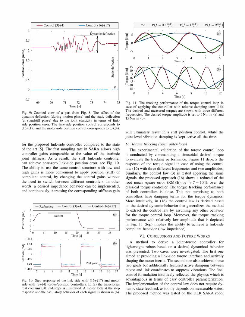
C. Vibration damping / stiff position controlOne experiment is carried out to validate the link-side
damping capabilities. As shown in Fig. 10 a combinedtrajectory that contains 0.01 rad steps is commanded witha limited rate in order not to violate the continuity propertyof the desired torque. The step response of the two controlstructures (3),(4) and (16),(17) employed as a stiff (high-gain) position controller is illustrated in Fig. 10.b. Theposition control gains are the same in the two cases andthe control gains of the torque control loop are computedbased on the same damping value D and the reductionratio of the apparent motor inertia. The highlighted peaksin Fig. 10.b. show an improvement of approximately 50%
69 70 71 72 73 74 75Time [s]
-0.5
0
0.5
1
1.5
2
2.5
3
Pos
itio
n er
ror
[mra
d]
Dynamic deflection
Sta
tic
defl
ecti
on
Control (16)-(17)Control (3)-(4)
Fig. 9: Zoomed view of a part from Fig. 8. The effect of thedynamic deflection (during motion phase) and the static deflection(at standstill phase) due to the joint elasticity in terms of link-side position error. The link-side position control corresponds to(16),(17) and the motor-side position control corresponds to (3),(4).
for the proposed link-side controller compared to the stateof the art [5]. The fast sampling rate in SARA allows highcontroller gains comparable to the value of the intrinsicjoint stiffness. As a result, the stiff link-side controllercan achieve near-zero link-side position error, see Fig. 10.The ability to use the same control structure with low andhigh gains is more convenient to apply position (stiff) orcompliant control, by changing the control gains withoutthe need to switch between different controllers. In otherwords, a desired impedance behavior can be implemented,and continuously increasing the corresponding stiffness gain
0 5 10 15 20 25 30 35Time [s]
-2
-1
0
1
2
Pos
itio
n [r
ad]
See (b) (a)
7 8 9 10 11 12 13 14 15 16 17Time [s]
1.485
1.49
1.495
1.5
1.505
1.51
1.515
Pos
itio
n [r
ad]
Peak point
(b)
Reference Control (3)-(4) Control (16)-(17)
Fig. 10: Step response of the link side with (16)-(17) and motorside with (3)-(4) torque/position controllers. In (a) the trajectoriesthat contains 0.01 rad steps is illustrated. A closer look at the stepresponse and the oscillatory behavior of each signal is shown in (b).
0 2 4 6 8 10 12Time [s]
-15-10
-516
51015
Torq
ue [
Nm
]
0 1 2 3 4 5 6Time [s]
-5
0
5
Torq
ue [
Nm
] (a)
(b)
Fig. 11: The tracking performance of the torque control loop incase of applying the controller with relative damping term (16).The desired and measured torques are shown with three differentfrequencies. The desired torque amplitude is set to 6 Nm in (a) and15 Nm in (b).
will ultimately result in a stiff position control, while thejoint-level vibration-damping is kept active all the time.
D. Torque tracking (open outer-loop)The experimental validation of the torque control loop
is conducted by commanding a sinusoidal desired torqueto evaluate the tracking performance. Figure 11 depicts theresponse of the torque signal in case of using the controllaw (16) with three different frequencies and two amplitudes.Similarly, the control law (3) is tested applying the samesignals, the proposed approach (16) shows a reduced of theroot mean square error (RMSE) by ≈ 7− 10% over theclassical torque controller. The torque tracking performanceof both controllers is close. This not surprising as bothcontrollers have damping terms for the torque dynamics.More intuitively, in (16) the control law is derived basedon the desired dynamic behavior that generalizes the methodto extract the control law by assuming any other behaviorfor the torque control loop. Moreover, the torque trackingperformance with relatively low amplitude that is depictedin Fig. 11 (top) implies the ability to achieve a link-sidecompliant behavior (low impedance).
VI. CONCLUSIONS AND FUTURE WORKS
A method to derive a joint-torque controller forlightweight robots based on a desired dynamical behaviorwas presented. Two cases were investigated. The first oneaimed at providing a link-side torque interface and activelyshaping the motor inertia. The second one also achieved thesetwo goals but additionally featured active damping betweenmotor and link coordinates to suppress vibrations. The finalcontrol formulation intuitively reflected the physics which isadvantageous in terms of easy controller parameterization.The implementation of the control law does not require dy-namic state feedback as it only depends on measurable states.The proposed method was tested on the DLR SARA robot
with high sampling rate which makes it possible to achievesuch a high link-side stiffness in practice. Experiments withan outer-loop, stiff position controller were shown and thetorque tracking performance was experimentally evaluated.Significant improvements in the static and dynamic link-sideposition errors were also achieved compared to the state ofthe art.
In the next step the link-side torque interface will beutilized to realize a coordinated, impedance-based multi-priority control behavior [21]–[23] with focus on highlydynamic task trajectory tracking [24].
REFERENCES
[1] A. De Luca and W. J. Book, “Robots with flexible elements,” inSpringer Handbook of Robotics. Springer, 2016, pp. 243–282.
[2] G. Hirzinger, N. Sporer, A. Albu-Schaffer, M. Hahnle, R. Krenn,A. Pascucci, and M. Schedl, “DLR’s torque-controlled light weightrobot III-are we reaching the technological limits now?” in Proc. ofthe 2002 IEEE International Conference on Robotics and Automation,May 2002, pp. 1710–1716.
[3] R. EMIKA., “This is Franka, [online]. available:https://www.franka.de/,” Jan. 23, 2017.
[4] N. Hogan, “Impedance Control: An Approach to Manipulation: PartI - Theory, Part II - Implementation, Part III - Applications,” Journalof Dynamic Systems, Measurement, and Control, vol. 107, pp. 1–24,March 1985.
[5] A. Albu-Schaffer, C. Ott, and G. Hirzinger, “A unified passivity-based control framework for position, torque and impedance control offlexible joint robots,” The international journal of robotics research,vol. 26, no. 1, pp. 23–39, 2007.
[6] P. Tomei, “A simple pd controller for robots with elastic joints,”Automatic Control, IEEE Transactions on, vol. 36, no. 10, pp. 1208–1213, Oct 1991.
[7] R. Ortega, R. Kelly, and A. Loria, “A class of output feedbackglobally stabilizing controllers for flexible joints robots,” Robotics andAutomation, IEEE Transactions on, vol. 11, no. 5, pp. 766–770, Oct1995.
[8] L. Zollo, A. De Luca, and B. Siciliano, “Regulation with on-linegravity compensation for robots with elastic joints,” in Robotics andAutomation, 2004. Proc. 2004 IEEE International Conference onRobotics and Automation, April 2004, pp. 2687–2692.
[9] C. Ott, A. Albu-Schaffer, A. Kugi, and G. Hirzinger, “On the Passivity-Based Impedance Control of Flexible Joint Robots,” IEEE Transac-tions on Robotics, vol. 24, no. 2, pp. 416–429, April 2008.
[10] I. Sardellitti, G. Medrano-Cerda, N. Tsagarakis, A. Jafari, and D. Cald-well, “Gain scheduling control for a class of variable stiffness actuatorsbased on lever mechanisms,” Robotics, IEEE Transactions on, vol. 29,no. 3, pp. 791–798, June 2013.
[11] F. Petit and A. Albu-Schaffer, “State feedback damping control for amulti dof variable stiffness robot arm,” in Proc. IEEE Int. Conf. onRobotic and Automation, 2011.
[12] M. Keppler, D. Lakatos, C. Ott, and A. Albu-Schaffer, “ElasticStructure Preserving (ESP) Control for Compliantly Actuated Robots,”IEEE Transactions on Robotics, vol. 34, no. 2, pp. 317–335, March2018.
[13] ——, “Elastic structure preserving (espi) control of compliantly ac-tuated robots,” in 2018 IEEE International Conference on IntelligentRobots and Systems (IROS). IEEE, October 2018, pp. 5861–5868.
[14] M. W. Spong, “Modeling and Control of Elastic Joint Robots,” Journalof Dynamic Systems, Measurement, and Control, vol. 109, no. 4, pp.310–319, December 1987.
[15] S. Wolf and M. Iskandar, “Extending a dynamic friction model withnonlinear viscous and thermal dependency for a motor and harmonicdrive gear,” in 2018 IEEE International Conference on Robotics andAutomation (ICRA). IEEE, May 2018, pp. 783–790.
[16] M. Iskandar and S. Wolf, “Dynamic friction model with thermaland load dependency: modeling, compensation, and external forceestimation,” in 2019 IEEE International Conference on Robotics andAutomation (ICRA). IEEE, May 2019, pp. 7367–7373.
[17] S. Wolf and M. Iskandar, “Verfahren zur parametrischen Model-lierung von Reibung und Reibungskompensation mit nichtlinearenAnhangigkeiten von Temperatur, Last und Geschwindigkeit,” Germanpatent No. DE 10 2019 112 611, patented on May 15, 2019.
[18] L. Le Tien, A. Albu-Schaffer, A. De Luca, and G. Hirzinger, “Frictionobserver and compensation for control of robots with joint torque mea-surement,” in 2008 IEEE/RSJ International Conference on IntelligentRobots and Systems. IEEE, 2008, pp. 3789–3795.
[19] C. Ott, A. Albu-Schaffer, A. Kugi, and G. Hirzinger, “DecouplingBased Cartesian Impedance Control of Flexible Joint Robots,” inProc. of the 2003 IEEE International Conference on Robotics andAutomation, September 2003, pp. 3101–3107.
[20] A. Albu-Schaffer, C. Ott, and G. Hirzinger, “A Passivity BasedCartesian Impedance Controller for Flexible Joint Robots - Part II:Full State Feedback, Impedance Design and Experiments,” in Proc. ofthe 2004 IEEE International Conference on Robotics and Automation,April 2004, pp. 2666–2672.
[21] A. Dietrich, T. Wimbock, A. Albu-Schaffer, and G. Hirzinger, “Re-active Whole-Body Control: Dynamic Mobile Manipulation Using aLarge Number of Actuated Degrees of Freedom,” IEEE Robotics &Automation Magazine, vol. 19, no. 2, pp. 20–33, June 2012.
[22] A. Dietrich, C. Ott, and A. Albu-Schaffer, “An overview of null spaceprojections for redundant, torque-controlled robots,” InternationalJournal of Robotics Research, vol. 34, no. 11, pp. 1385–1400, Sept.2015.
[23] M. Iskandar, G. Quere, A. Hagengruber, A. Dietrich, and J. Vogel,“Employing whole-body control in assistive robotics,” in IEEE In-ternational Conference on Intelligent Robots and Systems, November2019, pp. 5643–5650.
[24] A. Dietrich and C. Ott, “Hierarchical Impedance-Based TrackingControl of Kinematically Redundant Robots,” IEEE Transactions onRobotics, vol. 36, no. 1, pp. 204–221, February 2020.