50
Joint Task Force on Networked Media (JT-NM) Phase 2 Report Reference Architecture v1.0 4 September, 2015 For more info, go to jt-nm.org

Joint Task Force on Networked Media (JT-NM)
Phase 2 Report
Reference Architecture v1.0
4 September, 2015
For more info, go to jt-nm.org

EBU/SMPTE/VSF JT-NM Reference Architecture
This work is licensed under a Creative Commons Attribution-NoDerivs 3.0 Unported 1
Ownership and copyright
This work is jointly and severally owned by the European Broadcasting Union (EBU), the
Society of Motion Picture and Television Engineers (SMPTE) and the Video Services Forum
(VSF), and is licensed under the Creative Commons Attribution-NoDerivs 3.0 Unported License.
To view a copy of this license, visit http://creativecommons.org/licenses/by-nd/3.0/ or send a
letter to Creative Commons, 444 Castro Street, Suite 900, Mountain View, California, 94041,
USA.
Requests for waivers to allow you to use this work in derivative works should be sent to jt-nm-

EBU/SMPTE/VSF JT-NM Reference Architecture
This work is licensed under a Creative Commons Attribution-NoDerivs 3.0 Unported 2
Contents
Ownership and copyright ........................................................................................................... 1
What is JT-NM? ......................................................................................................................... 3
Purpose, Motivation and Scope ................................................................................................. 3
Reference Architecture .............................................................................................................. 4
Hierarchy of Architectures ...................................................................................................... 4
Context of the JT-NM RA........................................................................................................ 6
Systems Architecture ................................................................................................................. 8
Layered view .......................................................................................................................... 8
Capabilities view ..................................................................................................................... 9
Conceptual model .....................................................................................................................11
Foundational Frameworks .........................................................................................................14
Identity Framework ................................................................................................................14
Timing Framework .................................................................................................................17
Discovery & Registration Framework .....................................................................................22
Other System Capabilities .........................................................................................................30
Making the Reference Architecture Real ...................................................................................34
Device Interconnection Illustration .........................................................................................34
Connection Management.......................................................................................................35
Appendix A - Model views .........................................................................................................37
Why modeling ........................................................................................................................37
Data Model ............................................................................................................................37
Timing model .........................................................................................................................42
Networked media resource dynamics ....................................................................................43
Appendix B - Glossary of terms .................................................................................................45
Acknowledgements ...................................................................................................................49

EBU/SMPTE/VSF JT-NM Reference Architecture
This work is licensed under a Creative Commons Attribution-NoDerivs 3.0 Unported 3
JT-NM Reference Architecture
What is JT-NM?
The Joint Task Force on Networked Media (JT-NM) was formed by the European Broadcasting
Union, the Society of Motion Picture and Television Engineers and the Video Services Forum in
the context of the transition from purpose-built broadcast equipment and interfaces (SDI, AES,
crosspoint switcher, etc.) to IT-based packet networks (Ethernet, IP, servers, storage, cloud,
etc.) that is currently taking place in the professional media industry.
The Task Force was set up to foster discussion among subject-matter experts and to drive the
development of an interoperable network-based infrastructure for live media production,
encompassing file-based workflows. It brings together broadcasters, manufacturers, standards
bodies and trade associations.
This is a critical activity, as the dynamics of the industry are rapidly changing, with new players
vying for a share of the revenue pie and with ever-changing viewer consumption habits. Not
only do media companies need to be more flexible in order to respond quickly to new
opportunities to leverage or monetize content, but they also need to be able to take advantage
of economies of scale by leveraging the massive R&D investments being made in IT. The JT-
NM counts more than 300 participants from 175 organizations. More information on the JT-NM
including its scope and previously published works may be found on our website jt-nm.org.
Purpose, Motivation and Scope
The mission of the Joint Task Force on Networked Media is as follows: In an open, participatory
environment, help to drive development of an interoperable packet-based network infrastructure
for the professional media industry by bringing together manufacturers, broadcasters and
industry organizations (standards bodies and trade associations) with the objective to create,
store, transfer and stream professional media.
The motivation for the effort rests in the belief that new business opportunities will be enabled
through the exchange of professional media, including file-based and live content, across a
network, taking advantage of the benefits of IT-based technology at an affordable prices.
The scope of the effort is not simply to find a way to replace SDI with Ethernet, but to find ways
to employ internet technology at the core of our business.
At the conclusion of the JT-NM’s initial phase, it was not clear how the technologies offered in
response to the RFT we issued could be used to create a coherent system. For that reason, the

EBU/SMPTE/VSF JT-NM Reference Architecture
This work is licensed under a Creative Commons Attribution-NoDerivs 3.0 Unported 4
sponsors of the task force decided to initiate this second phase of work. The goal of this phase
is to create a reference architecture.
This is Version 1.0 of the JT-NM Reference Architecture. That said, this is not a Standard upon
which systems will be based, but rather a collection of best practices, recommendations, and
frameworks which readers may choose to implement. It is expected that this Reference
Architecture will evolve over time. However, those considering implementing professional
networked media infrastructures are encouraged to review the suggestions contained in this
document and to begin implementing them as soon as practical.
This is an ongoing development with the anticipation that, over time, it will facilitate
interoperability as manufacturers develop, and users deploy professional networked media
facilities. The goal of this effort is not to write a standard but to set an overall strategic approach
for the industry. It is recognized that additional detail will be necessary in the reference
architecture if the JT-NM is to achieve its goal of increasing the level of interoperability between
professional networked media implementations. The sponsors are considering continuing the
development of this Reference Architecture in a future phase.
Reference Architecture
A reference architecture is frequently used in the computer and software industry to facilitate the
development of systems that are multi-vendor, multi-site or multi-organization. It provides a
common vision which can be propagated across an industry, using a common lexicon and
taxonomy. It serves as a baseline for near-term and future-oriented discussions, it aids in
documenting implicit knowledge and best practices, and it encourages the modularization of
functionality. The JT-NM Reference Architecture (RA) presented in this document is targeted at
the new domain of professional media that is based on packet-based network transport and
standard, rather than media-specific, computing, storage and network infrastructure.
It is recognized that there are two discrete audiences for this document – traditional
broadcasters and those from the IT community, and that the specific meaning of terms will differ
between these two communities. One of the purposes of this Reference Architecture is to
provide some definition and clarity regarding terminology used by professionals when describing
networked media. The terms used here have been chosen purposely, and the meanings of
those terms draw on both domains. Readers are encouraged to refer to the glossary in
Appendix B for specific definitions.
Hierarchy of Architectures
The JT-NM Reference Architecture provides principles and generalized models that can be
reused or easily adapted to the specific business context of an organization.

EBU/SMPTE/VSF JT-NM Reference Architecture
This work is licensed under a Creative Commons Attribution-NoDerivs 3.0 Unported 5
Figure 1: Hierarchy of architectures
From an organization-specific reference architecture, system architects can derive system
designs addressing specific operational scenarios which in turn can be implemented in real life
systems. The aim is that the JT-NM RA introduces key frameworks and concepts that will be
adopted by manufacturers and implemented in end-user facilities such that the task of
integrating disparate products is less difficult, and that overall interoperability of software in IT-
based media facilities is improved. The JT-NM RA was developed for a broad range of
operational scenarios, from conventional live TV production, radio production to web-first and
cross-media production (for many of Web, mobile, TV, radio, etc.). These workflows include a
combination of real-time, near real-time and non real-time workflows. It is hoped that this
approach will allow the industry to take advantage of the possibilities offered by networked
media architectures.
The JT-NM Reference Architecture is described through a number of different representations
or views. This set of representations is necessary to effectively explain and provide context for
the JT-NM RA.

EBU/SMPTE/VSF JT-NM Reference Architecture
This work is licensed under a Creative Commons Attribution-NoDerivs 3.0 Unported 6
The different representations are:
1. Conceptual Architecture – presenting core concepts used in describing the JT-NM
Reference Architecture Capabilities
2. Systems Architecture – presenting a layered view of how and where the capabilities
being delivered by the Reference Architecture fit into a larger architecture of an
organization. Two levels of depth are presented in this document. A high level Layered
view, and a more detailed Capabilities view of this Systems Architecture including
Foundational Frameworks and System Capabilities that together may be used to
connect devices and provision a facility.
3. Data Models – presenting the domain model relevant to the JT-NM scope. It is
represented using UML (Unified Modeling Language) notation. The data model details
Identity, Timing, and Discovery & Registration, since they are the focus of this phase of
the JT-NM work. A more complete data model is presented in Appendix A, which
provides greater context and specificity, and suggests how the JT-NM RA could be
used.
4. Dynamic Models – describing, by example, how to use the frameworks presented in
this document, and more generally, the overall JT-NM Reference Architecture. The
examples focus on the foundational frameworks (identity, timing, and Discovery &
Registration), and touch upon other system capabilities that must be delivered by the
Reference Architecture in the future (e.g. device and connection management). The
dynamic models are expressed using sequence diagrams (often called event trace
diagrams) which are part of UML notation.
Context of the JT-NM RA
Areas in color surrounded by a bold line in the layered model in Figure 2 are the focus of this
RA, and are shown within its overall business context.
As with every other layered diagram in this document, each layer defines a domain of
responsibility that serves the layer above it. This way of organizing responsibilities comes from
the networking paradigm (e.g., OSI model1, TCP/IP stack, etc.) and is a successful pattern that
enables composability in a system. The approach also allows a part of a system to be changed
without having to re-engineer the entire system.
1 http://en.wikipedia.org/wiki/OSI_model

EBU/SMPTE/VSF JT-NM Reference Architecture
This work is licensed under a Creative Commons Attribution-NoDerivs 3.0 Unported 7
Figure 2: Business Context - Focus of RA is inside of bold line.
The top layer concerns the Governance and Strategy aspects of the organization. This is
realized by offering the Products and Services that are in turn produced by the business
Operations. Operations are achieved by consuming the three layers of the technical systems:
business Applications, Platforms and Infrastructures. Facilities host the technical apparatus from
the Infrastructure layer, whether they are physical or virtual, in-house, external or hybrid.
Two key management aspects are represented across all layers since their role is to ensure that
the strategic objectives of the organization are achieved throughout all the layers: Security
Management and Service Management.
The JT-NM Reference Architecture presented in this document focuses on the three technical
layers – Applications, Platforms and Infrastructures.
Secu
rity
Man
agem
ent
Products & Services
Infrastructures
Operations
Applications
Platforms
Governance & Strategy
Serv
ice
Man
agem
ent
Facilities

EBU/SMPTE/VSF JT-NM Reference Architecture
This work is licensed under a Creative Commons Attribution-NoDerivs 3.0 Unported 8
Systems Architecture
Layered view
This following model provides a closer look at the operational and technical layers of the
business context view presented above.
Figure 3: Systems Architecture Layered view
● Operation Layer: This layer describes a business process overseen by humans.
Technology is not involved at this level. Think about the items in this layer as the
business functions the organization would like to accomplish, such as live studio
operations, post-production workflows and network origination functions. This layer is
not in scope of the JT-NM activity.
● Application Layer: This layer consists of software applications and user interfaces that
are used to accomplish the business processes. While traditionally this layer may have
consisted of a piece of hardware such as a video switcher or a CCU unit, now it is
common to find software user interfaces such as virtual router control panels using the
computing power in the Infrastructure Layer.
This layer is not in scope of the JT-NM activity (JT-NM will not be designing video
editors, for example). That said, the JT-NM RA does affect this layer; for example, the
RA describes how Capabilities might be exposed in the technical layers below, so that
they might be used by applications in this layer.
● Platform Layer: The software services in this layer provide the System Capabilities that
are required by the Application Layer above. Examples of System Capabilities include
Media Devices & Systems
Media Applications
Networks
Data Center & Specialty Hardware
OperationLayer
Application Layer
PlatformLayer
Infra-structure
Layer
Media Platforms
Media Operations Enterprise Operations
Enterprise Applications
Enterprise Platforms

EBU/SMPTE/VSF JT-NM Reference Architecture
This work is licensed under a Creative Commons Attribution-NoDerivs 3.0 Unported 9
timing, synchronization, and discovery & registration. These services exploit the
resources provided by the Infrastructure Layer below.
● Infrastructure Layer: This layer consists of two sub-layers: the Data Center & Specialty
Hardware and the Network sub-layers. Typical items included in the Data Center layer
are PC servers, storage arrays, GPU farms, hardware accelerators, IP/SDI gateways,
etc. The Networks sub-layer consists of network switches, various network transport
protocols, and physical transport mechanisms.
The vertical “Media Devices & Systems” represent the more conventional monolithic approach
where all the hardware, components and user interfaces are integrated in the same box. This
model shows how both monolithic systems and service-based systems can co-exist in a hybrid
JT-NM architecture, and provide a migration path from the former to the latter.
Another integration that is illustrated in the model is the “Enterprise” functions that can share
resources and services with “Media” functions. No longer are media operations an opaque box
to the Enterprise. Automated metadata extraction, for example, could be used to inform
business systems when particular content becomes available in a media operations area.
Capabilities view
In this section the layers of the Systems Architecture Layered view are expanded to provide
greater detail.
The Capabilities view’s focus is on the core System Capabilities needed to support a Networked
Media Reference Architecture. Conceptually, a media application in the application layer
consumes System Capabilities offered in the platform layer in order to perform Tasks on
Content.
Three fundamental System Capabilities have been identified as being essential to even the
most basic interoperability in professional networked media systems. These capabilities are
Identity, Timing, and Discovery & Registration. These are called Foundational Frameworks.
They are identified in bold in the Media Platform layer below and are discussed in further detail
later in this document. It is recognized that, in addition to these Foundational Frameworks,
other System Capabilities are required in a solution-specific system design for it to be usable.
Some of these functionalities are defined within the Capabilities View as subsystems and are
described later in the document under System Capabilities.
Structuring a system architecture into Foundational Frameworks and System Capabilities
reduces interdependency within a system and promotes loose coupling. These are key
architectural principles that can be used to manage complexity and enable reuse.

EBU/SMPTE/VSF JT-NM Reference Architecture
This work is licensed under a Creative Commons Attribution-NoDerivs 3.0 Unported 10
Figure 4: Systems Architecture Capabilities view
The Capabilities View in Figure 4 includes:
a. Foundational Frameworks (Timing, Identity, and Discovery & Registration) are
fundamental building blocks of interoperability in the professional networked media
infrastructure
b. System Capabilities (shown as bold, unshaded boxes, for example Connection
Management) are identified in the RA, and their responsibilities and relationships are
defined in the System Capabilities portion of the document below
c. Other System Capabilities providing capabilities in existing facilities such as SDI I/O are
shown in grey boxes with dimmed text.
d. Selected model elements are included from the Data Model presented in Appendix A
and are further introduced in the following Conceptual Model. They are represented on
this diagram to highlight the relationship between the two views, by showing the
mapping of model elements to the layers.

EBU/SMPTE/VSF JT-NM Reference Architecture
This work is licensed under a Creative Commons Attribution-NoDerivs 3.0 Unported 11
Another fundamental precept of the Reference Architecture is the notion of Resources.
Readers coming from a broadcast background might want to familiarize themselves with this
concept from the IT domain, wherein everything within a system is a Resource and where each
Resource is uniquely identified. The notion of Resources and their identity is a great aid in
reuse and composability, two well-proven patterns of software development. This use of the
word is subtly different from the common meaning of the word resource. Readers seeking to
learn more about this concept are referred to the Web Characterization Terminology &
Definitions Sheet2.
Conceptual model
As workflows transition from today’s media devices and systems to tomorrow’s corresponding
Systems Architecture layer in data centers, the concepts of a shared model enable
interoperability. Here is a brief overview of the informative conceptual model shown in Figure 5
below.
There are many ways of explaining the conceptual model, starting with the infrastructure
elements and reading down, starting with the elements of data and their timing and reading up,
or starting from a business perspective with the content that needs to be leveraged or
monetized. The reality is that this is a multidimensional model that can only be expressed in a
limited way on one sheet of paper. The first model description below reads from the top left
down, and is an infrastructure-first description - keep reading this document for other
perspectives.
At the heart of networked media operations is the Network, typically a packet-based Ethernet
network. Nodes are connected to Networks to provide additional infrastructure such as
processing power, storage and interfaces. Devices, which may be software-only services or
physical Devices, such as a camera, are deployed onto the Nodes to provide the Capabilities
required to complete Tasks in a facility.
Devices can be Sources for Essences and related data, such as a camera, microphone or a
mixer. Where traditional facilities use connections over physical wires to move Essences
between Devices, networked media facilities will typically move Essences as Grain Payloads
that are subdivided into network packets for transportation.
When Essences move over the Network, a connection exists between a Sender on one Device
and a Receiver on another. Information, including Essences, moves between Senders and
Receivers in the form of Flows, where a Source may provide different qualities for each of its
Essences for each Flow, such as uncompressed, mezzanine and/or proxy. Each Flow consists
of a number of Grains, where each Grain represents an element of Essence such as a video
frame, or frames-worth of audio samples, or time-varying camera position data. With reference
to a Clock, each Grain consists of a Grain Payload and a Time Stamp which notes the time that
2 http://www.w3.org/1999/05/WCA-terms/

EBU/SMPTE/VSF JT-NM Reference Architecture
This work is licensed under a Creative Commons Attribution-NoDerivs 3.0 Unported 12
the Grain Payload was recorded, along with a unique identity assigned in accordance with this
RA. A Grain may also contain data.
Figure 5: Conceptual model

EBU/SMPTE/VSF JT-NM Reference Architecture
This work is licensed under a Creative Commons Attribution-NoDerivs 3.0 Unported 13
Essences are normally experienced through the playing of a live or recorded Rendition
comprising a collection of time-synchronized Flows (e.g., proxy-quality video with its associated
audio tracks). Renditions can be stored in files or streamed over networks. Different qualities of
Flow provide different representations of a Source (e.g. a High res and a proxy-quality of the
same video). When managing these different representations during or after production, it is
convenient to collect together related Sources into Source Groups that are virtual containers for
related material. Different kinds of Source Group will be identified in the future, including ones
for representing editorial compositions, but in their simplest form, examples of Source Group
include:
● all Sources related to the same camera (“Camera 4”’s video and audio);
● all Sources available as inputs to the mixer in a broadcast truck at a sports game;
● the output of the truck’s mixer as received back at base, combined with an additional
foreign language audio Source. Such a Source Group (not all) may realize a Content
deliverable - the broadcast of the game.
As part of business operations, Content is source-material that can be transformed by Tasks
using a method defined by a Capability which is provided by a Device or Devices. For example,
a workflow engine runs a job that controls a transcoder to transform material ready for delivery
to a mobile phone platform.
The final piece of the jigsaw is a Registry that keeps track of the current state of the
infrastructure and media, so that they can be registered, discovered, and so that connections
between Senders and Receivers can be determined. A Registry may be federated across more
than one site to make each site appear as part of the same network. As the networked
resources may be virtual, the Registry is the place where the dynamic structure of a networked
media facility can be established.
EBU/SMPTE/VSF JT-NM Reference Architecture
This work is licensed under a Creative Commons Attribution-NoDerivs 3.0 Unported 14
Foundational Frameworks
This section details the Frameworks for Identity, Timing, and Discovery & Registration. Each of
these frameworks is defined according to the following template:
● Introduction - an overview of the approach
● Prescriptive - required behavior for implementation
● Best Practices - the best practices noted below are recommended for JT-NM-based
system designs
● Models - Models illustrating the framework
● Standards - An overview of existing standards that can be used in implementations
● Examples - Examples of how the framework can be used for some typical scenarios
Identity Framework
Introduction
The JT-NM Reference Architecture rides on the common currency that is the Internet, through
the elements of Unique Resource Identifiers (URNs/URLs) and hyperlinks. The JT-NM Identity
Framework includes three rules, which are listed below. Every element of the architecture has a
name, which in turn means it is a Resource that anyone could make reference to. When applied
to professional media, Identity is a core concept in software-based systems that facilitate
interoperability and reuse of generic Internet technologies.
For a description of the architecture of identification on the Internet, see
http://www.w3.org/TR/webarch/#identification.
Prescriptive
1. Internet-style Unique Resource Identifiers (Internet Standard STD 66 and RFC 3986)
shall be used to identify the Resources of networked media, including Discoverables,
where every addressable instance of a class in the JT-NM models is a Resource with at
least one identity.
2. Identity is a logical indirection that shall be resolvable to provide access to a
representation of a Resource, as per RESTful principles3, hiding form, location and
function. Conceptually, physical-resources are not addressed directly.
3. Relationships between Resources shall be expressed using identifiers and only through
identifiers. Change shall be managed as a kind of relationship, whereby a reference to
3 https://www.ics.uci.edu/~fielding/pubs/dissertation/rest_arch_style.htm

EBU/SMPTE/VSF JT-NM Reference Architecture
This work is licensed under a Creative Commons Attribution-NoDerivs 3.0 Unported 15
the current version of a Resource is a pointer to an Immutable Object that is the latest
revision.
Best Practices
● Universally Unique Identifiers (UUIDs) [RFC 4122] can be generated locally without
reference to a central authority, and pseudo-random UUIDs (type 4) have sufficient
randomness that they can be generated without clashes - even on a global scale. UUIDs
are commonly used where automatic identity generation is required across network
Nodes, with a specified mapping to a URN. However, that URN is rarely resolved directly
and the UUID is used as part of a URL.
● The Internet’s domain name registration services provide the owner of a domain with a
limitless number of unique resource locations, where each identifier includes the domain
name. For example, an e-mail address ([email protected]) or the address of a
webpage (http://www.broadcaster.com/contact.html). In this way, literally billions of
Internet identifiers are available for the cost of a domain name registration with the
consequence that managing globally unique identity can be achieved locally by
managing paths within a domain.
● One Resource may have more than one identifier. Redirection is a common practice on
the Internet, whereby a Resource is referenced by an identifier that is actually a pointer
to another identifier. In this way, Internet identity can change to track changes in real-
world identity, such as one company being sold to another.
● Query parameters and fragments are not considered as part of an identifier. Query
parameters are particularly used to filter result sets.
● If a Resource has many revisions, the following path pattern can be used to access each
revision as a subresource:
○ Implicit reference to the current version: http://www.facility.com/resource/
{unique-id}
○ Explicit reference to the current version: http://www.facility.com/resource/
{unique-id}/latest
○ Explicit reference to version 3 of unique-id:
http://www.facility.com/resource/{unique-id}/revisions/3
○ List of all available revisions: http://www.facility.com/resource/
{unique-id}/revisions
EBU/SMPTE/VSF JT-NM Reference Architecture
This work is licensed under a Creative Commons Attribution-NoDerivs 3.0 Unported 16
Model
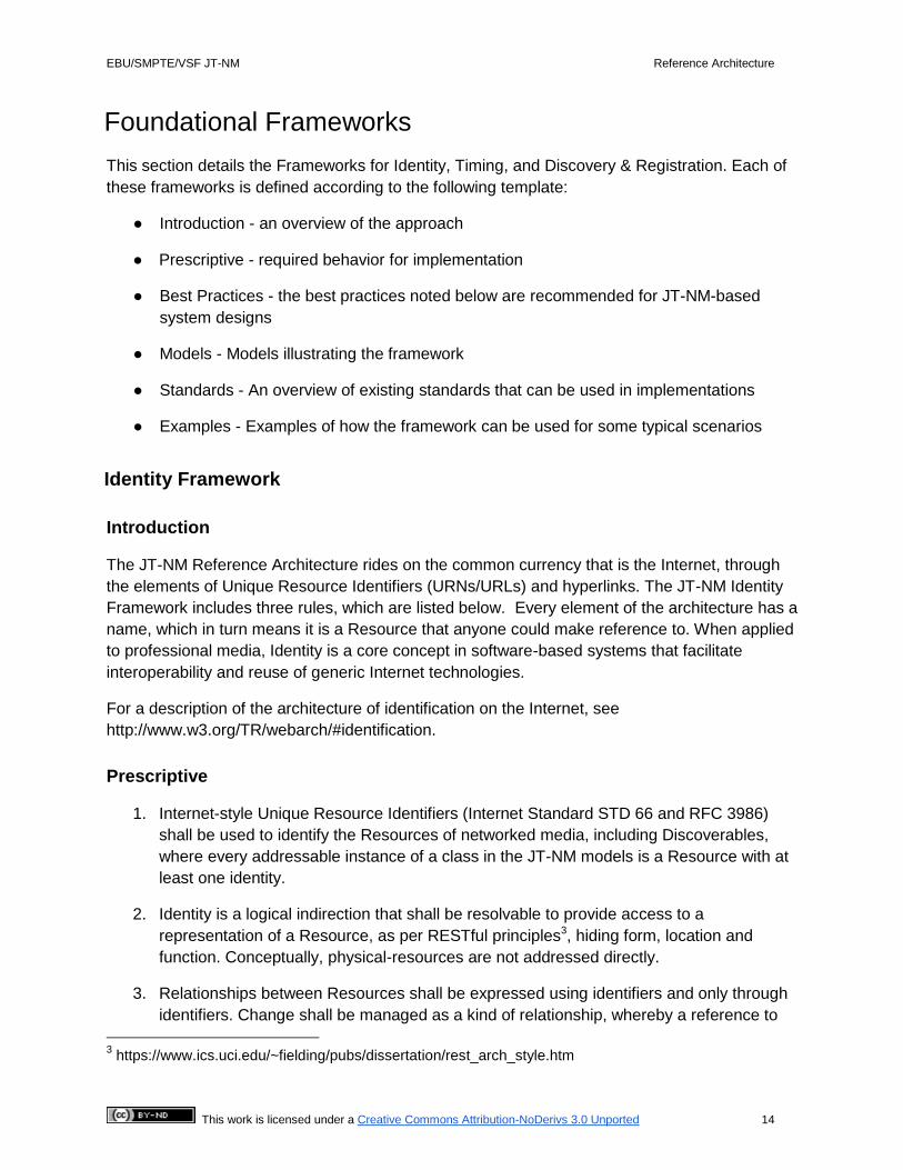
Figure 6: Identity model
An ID provides identification for all Resources and any other identifiable classes of the reference
architecture. An ID may have one or more URIs and it is best practice to record the revision
number of the Resource so that distributed copies of a Resource can be compared like-for-like
and any genuine conflicts detected. IDs are Stable Identifiers for Immutable Objects. For
reasons of detecting errors in data payloads or conflict resolution, a checksum or hash value
may be generated from the content of the Resource.
Standards
IETF RFC 4122 ‘A Universally Unique IDentifier (UUID) URN Namespace’
A 16-byte number that is in common use across the IT industry. With 2122 unique values,
a type 4 pseudo-random UUID can be generated locally with a very high degree of
likelihood of not clashing, allowing for loosely coupled generation of identifiers across
wide area networks without the need for a central brain. Normally formatted as a
hexadecimal string.
IETF STD 66, RFC 3986 ‘Uniform Resource Identifier (URI): Generic Syntax.'
URIs are the identifiers of the Internet. Of particular interest are http: URLs that have
become de facto due to their support in web browsers and the global domain name
systems. See http://www.w3.org/2001/tag/doc/URNsAndRegistries-50 for further
discussion.
Examples
The following three identifiers are for the same channel in a mixing desk:
● urn:uuid:DBC31256-A110-4BB1-8388-C2F55B372538
● http://registry.broadcaster.com/news/recievers/DBC31256-A110-4BB1-8388-
C2F55B372538
● http://registry.broadcaster.com/news/recievers/mixingdesk3/input7

EBU/SMPTE/VSF JT-NM Reference Architecture
This work is licensed under a Creative Commons Attribution-NoDerivs 3.0 Unported 17
Timing Framework
Introduction
The Timing Framework uses Time Stamps to ensure that Flows are appropriately aligned during
switching, mixing, presentation and other professional media network operations. The Time
Stamps are associated with Grains - representations of elements of Essence or other data at a
particular time (for example a video frame).
Accurate timing is critical to professional media operations. It allows for proper lip sync and
phase alignment. Timing is also critical for accurately identifying segments in the non-linear
editing process, and for automated recording and playback of linear streams.
Prescriptive
Time Stamp and Time Base
● Every Grain shall have a Time Stamp
● Flows shall be synchronized using Time Stamps
Time Stamps shall be expressed in the units of the Time Base and derived from a network-
distributed Clock.
Synchronization
● Audio/Video Synchronization - The Synchronization method shall allow for
Synchronization of audio and video within the bounds of EBU TR R37-2007.
● Multi-Channel Audio Imaging Synchronization – The Synchronization method shall allow
for Synchronization of multiple channels of audio intended for synchronized audio
imaging to within 10 µs.
● Number of Phase Aligned Groups - The Synchronization mechanism shall provide for
multi-channel audio imaging Synchronization for any number of mono channels.
● Data Synchronization – Data shall be able to be synchronized to an associated Grain.
This includes synchronization of SDI Ancillary Data to a video Grain (frame) for support
of existing workflows.
Best Practices
Time Stamp and Time Base
● SMPTE ST 12-1 (formerly known as “SMPTE 12M”) Timecode should be derived from
networked distributed time as per SMPTE ST 2059-1. Note: this requires use of

EBU/SMPTE/VSF JT-NM Reference Architecture
This work is licensed under a Creative Commons Attribution-NoDerivs 3.0 Unported 18
additional metadata such as that carried in the SMPTE PTP profile specified in ST
2059-2
● The Time Stamp for video should be the time of the capture of the top of the field
(interlaced) or the top of the frame (progressive), and for audio should be the time of the
first sample of the Grain.
● Clocks should use the PTP timescale
● Time Stamps should have an origin (zero point) of the SMPTE Epoch as defined in
SMPTE ST 2059-1
● For offline-generated Flows, such as computer generated video and non-linear edited
Essence, Time Stamps may be synthesized in a process that is not necessarily real
time, so as to align the Flow in time with other, live captured, Flows
Synchronization
● Clock Synchronization - Synchronization of Clocks on Devices should be achieved
through network transmissions
● Legacy Timing Support - It should be possible to generate a Clock from a legacy
Synchronization signal (such as black burst and Timecode + date)
● Slave Synchronization - Slave Clocks should be synchronized to the master with an
accuracy of 1µs within 5 seconds of connection to the network
● Multiple Camera Synchronization Requirement – The Synchronization system should
support the ability to have the capture of video from multiple cameras with the
Synchronization of raster sampling within ±2 µs
This is provided so that in live capture, a switch or fade between cameras pointed at the same
object is undetectable. The ±2 µs timing is based on the length of the SMPTE RP 168 switch point
for 720p59.94, which is the shortest SMPTE RP 168 switching area (4.37 µs). This requirement
may be overly stringent, but without additional information it is difficult to relax this constraint. Many
applications require considerably less stringent tolerance.

EBU/SMPTE/VSF JT-NM Reference Architecture
This work is licensed under a Creative Commons Attribution-NoDerivs 3.0 Unported 19
Model
Below is a UML model that shows the elements of timing & synchronization.
Figure 7: Timing model
The elements of this model include:
● Clock: a networked component providing a ubiquitous time reference.
● Epoch: identifies the zero value of a Clock.
● TimeBase: specifies the units used for measuring time. Expressed as a rational (or
integer) number of units per second.
● Grain: represents an element of Essence or other data associated with a specific time,
such as a frame, or a group of consecutive audio samples, or captions.
● TimeStamp: an absolute time (that is, an offset from an Epoch) describing the
relationship of a Grain with a Clock.
Standards
IEEE 1588-2008 “IEEE Standard for a Precision Clock Synchronization Protocol for Networked
Measurement and Control Systems”
A protocol is provided in this standard that enables precise synchronization of Clocks
communicating via packet network, otherwise known as “Precision Time Protocol”
(PTP). A PTP time stamp is a representation of time elapsed from the PTP Epoch (1
January 1970 00:00:00 TAI) stored as 48 bits of seconds and 32 bits of nanoseconds.
SMPTE ST 2059-1 “Generation and Alignment of Interface Signals to the SMPTE Epoch”
Definition of the SMPTE Epoch, and mechanism for alignment of legacy analog and
serial digital interfaces to a PTP time. The SMPTE Epoch is the same as the PTP
Epoch (1 January 1970 00:00:00 TAI).

EBU/SMPTE/VSF JT-NM Reference Architecture
This work is licensed under a Creative Commons Attribution-NoDerivs 3.0 Unported 20
SMPTE ST 2059-2 “SMPTE Profile for Use of IEEE-1588 Precision Time Protocol in
Professional Broadcast Applications”
A PTP profile designed to provide for synchronization of 1 µs accuracy within 5 seconds
of connection to an operational PTP network, and also to convey Synchronization
Metadata required for synchronization and time labeling of audio/video signals.
IETF RFC 7273 “RTP Clock Source Signaling”
Specifies Session Description Protocol (SDP) signaling that identifies Time Stamp
reference Clock sources (such as PTP) and SDP signaling that identifies the media
clock sources in a multimedia session.
Examples
The diagram below shows a potential implementation of a PTP-based timing solution.
Figure 8: Potential implementation of a PTP-based timing solution
A master clock is distributed to all Nodes in the local area network from a PTP Grandmaster
using IEEE 1588 PTP. Synchronization between PTP Grandmasters over the wide area is
achieved through the use of a common GPS Clock reference.

EBU/SMPTE/VSF JT-NM Reference Architecture
This work is licensed under a Creative Commons Attribution-NoDerivs 3.0 Unported 21
Figure 9: Potential implementation of a PTP-based timing solution
As video essence and audio essence are acquired, the master clock is sampled and the value
used to generate a Time Stamp that is bound to the resulting Grains, where each Grain
represents an element of Essence or other data. Grains are transported over the network,
received by the viewer Device and placed in a buffer ordered by Time Stamp.
The clock used for presentation of the video and audio is offset (delayed) from the master clock
by an amount necessary to compensate for processing and network delays and to integrate any
packet jitter introduced by the system. Grains are presented from the receive buffer when the
presentation clock value reaches their Time Stamp value. Since the master clock is distributed
to every Node this technique can be used to synchronize presentation across multiple Nodes.

EBU/SMPTE/VSF JT-NM Reference Architecture
This work is licensed under a Creative Commons Attribution-NoDerivs 3.0 Unported 22
Discovery & Registration Framework
Introduction
Discovery & Registration ensure that parts of a networked infrastructure can find each other,
and obtain appropriate information about each other. The following summarizes a proposed set
of patterns:
● Registries, which may be distributed across multiple hosts, hold information about
Discoverables such as Devices and Sources. This information includes unique
identification and other data (e.g., human-readable labels)
● Nodes, which host Devices, register and de-register Discoverable information through a
Registration Interface, and provide regular health information concerning the continued
availability of Discoverables
● Clients use a Query Interface to access Discoverable information. This can be on a one-
off or subscription basis
● The Registration and Query Interfaces can be discovered through Advertisements to the
network
● Applications can obtain information about connections between Senders and Receivers
through the Query Interface
● To support minimal (point-to-point) applications without a Registry on the network,
Nodes can make Advertisements of their Discoverables to the local network
Prescriptive
The Discovery and Registration Framework requires the following:
● Registration and Query Interfaces shall be discoverable over the network
● A Node shall check periodically for the existence of a Registration Interface, and if this is
present, the Node shall register each of its Discoverables with the Interfaces. A Node
shall de-register (using the Registration Interface) Discoverables that are no longer
available
● An application or Device shall not use other (“out of band”) mechanisms to communicate
information that should be communicated through the mechanisms described here. It
shall only communicate with a Registry through the Registration and Query Interfaces

EBU/SMPTE/VSF JT-NM Reference Architecture
This work is licensed under a Creative Commons Attribution-NoDerivs 3.0 Unported 23
Best practices
Beyond the prescribed behavior above, current best practices suggest the following:
● Discovery & Registration are logically decoupled activities: discovery enables connection
to an Endpoint, while registration enables querying of a Node’s Discoverables
● The choice of technology used for discovery (e.g., DNS-SD over multicast DNS) is
independent of the choice of technology used for registration and query (e.g., HTTP)
● In some implementations it is desirable that Devices be responsible for providing health
information, such as through a heartbeat mechanism. This allows a Device’s
Discoverables to be de-registered if it stops communicating
● In some implementations, push transfer of registration, de-registration and health
information is desirable. (Polling is an anti-pattern that does not scale well.)
● Multiple Registries, possibly with different implementations or optimizations, may be
hidden behind the Registration and Query Interfaces
● Details of how a Registry works (including any internal protocols used in a distributed
Registry) should not be exposed through the Interface, nor should knowledge of how the
Registry works internally be necessary in order to make use of the Interface.
Furthermore, this framework does not specify or assume technology for the Registry, nor
establish any requirements concerning its characteristics or performance.
Several implementations of distributed databases are available. The Raft
[http://raftconsensus.github.io/] and Paxos
[http://research.microsoft.com/users/lamport/pubs/pubs.html#reaching] consensus
algorithms may provide suitable bases for some applications. The “etcd” open source
project [https://github.com/coreos/etcd] is an example of a distributed database that uses
the Raft algorithm.
● In some implementations, it is more efficient to simultaneously discover and register
multiple Devices hosted on the same Node
● The application of web-based protocols and patterns (e.g. REST APIs) can facilitate
problem solving, faster development cycles and simplified system integration.
● Any framework implementation should scale from a two-box solution to a global network
potentially consisting of many thousands of Devices.
● Peer-to-peer operation without Registration and Query Interfaces may be appropriate in
some cases. In such cases a Node should provide information about its own
Discoverables through the Node Interface and is responsible for maintaining its own
(internal) Registry of Discoverables on other Nodes. To enable discovery, a Node can
create multicast DNS-SD Advertisements for each Discoverable available on its

EBU/SMPTE/VSF JT-NM Reference Architecture
This work is licensed under a Creative Commons Attribution-NoDerivs 3.0 Unported 24
Device(s). The service type indicates the type of Discoverable, e.g. _jtnm-
source._tcp.
● It should be possible to support operation in a “zero-configuration” environment in which
Nodes can determine their own IP addresses and local domain names.
● In some implementations, policy-based Advertisements customize interconnection
between different organizations/domains. For example, a provider may wish to expose a
subset of Sources which are available for a particular remote production.
Model
Figure 10: Model for discovery and registration
Figure 10 shows the elements of the framework model relevant to discovery and registration:
● Devices are hosted by Nodes.
● Devices offer Capabilities.
● Devices can provide Sources of Flows.
● Devices can have Senders and Receivers for Flows.

EBU/SMPTE/VSF JT-NM Reference Architecture
This work is licensed under a Creative Commons Attribution-NoDerivs 3.0 Unported 25
● Nodes, and their associated Devices, Capabilities, Sources, Flows, Senders and
Receivers are Discoverables. NB: For clarity Discoverable is not shown in Figure 10.
Other types of Resources may also be Discoverables; however the current RA does not discuss such cases.
● Nodes register Discoverables with a Registry through a Registration Interface.
● Client applications use a Query Interface to find Discoverables.
● Advertisements announce the Registration and Query Interfaces, and (for peer-to-peer
discovery) a Node’s Discoverables, and allow a client application to resolve the
corresponding Interfaces.
Standards
IETF RFC 6763 “DNS-Based Service Discovery”
DNS-SD provides one implementation of Advertisements. The service type can be used
to indicate the type of Interface or Discoverable (e.g., _jtnm-query._tcp, _jtnm-
device._tcp). The SRV record of the DNS-SD message allows a client to resolve the
Endpoint.
IETF RFC 6762 “Multicast DNS”
Multicast DNS can be used to distribute DNS-SD Advertisements within LANs. This
standard also enables Nodes to determine their own .local domain names in an zero-
configuration environment.
Many scenarios may use an architecture with a registry distributed across multiple interconnected LANs. In
this case multicast DNS announcements are sufficient to discover and resolve the Registration and Query
Interfaces.
IETF RFC 3986 “Uniform Resource Identifier (URI): Generic Syntax”
URLs provide a widely-adopted representation of Endpoints.
IETF RFC 2616 “Hypertext Transfer Protocol -- HTTP/1.1”
HTTP provides a suitable protocol to implement Interfaces.
Although REST is not a standard, it is appropriate to use a RESTful approach
[https://en.wikipedia.org/wiki/Representational_state_transfer] based on standard HTTP verbs acting on
representations of Discoverables, for example HTTP PUT and DELETE for registration and de-registration
and HTTP GET for query.
IETF RFC 6455 “The WebSocket Protocol”
Subscription to a Query Interface can be implemented using RESTful HTTP to set up
and tear down the subscription and WebSockets for the ongoing information feed.

EBU/SMPTE/VSF JT-NM Reference Architecture
This work is licensed under a Creative Commons Attribution-NoDerivs 3.0 Unported 26
IETF RFC 7159 “The JavaScript Object Notation (JSON) Data Interchange Format”
JSON can be used for representation of Discoverables for the Registration and Query
APIs.
IETF RFC 3927 “Dynamic Configuration of IPv4 Link-Local Addresses”
IETF RFC 4291 “IP Version 6 Addressing Architecture”
These two standards allow Nodes to determine their own IP addresses in a zero-
configuration environment.

EBU/SMPTE/VSF JT-NM Reference Architecture
This work is licensed under a Creative Commons Attribution-NoDerivs 3.0 Unported 27
Examples
This section uses UML sequence diagrams to demonstrate examples of Discovery and
Registration patterns. They assume implementation with multicast DNS-SD and RESTful
HTTP/JSON.
Registration
Figure 11 shows an example of registering a networked audio Device producing a 24-bit
uncompressed signal in an RTP stream. The Node hosting the Device discovers a Registration
Interface and registers (in sequence) itself, a Device, a Source, a Flow and a Sender.
Figure 11: Registration sequence
EBU/SMPTE/VSF JT-NM Reference Architecture
This work is licensed under a Creative Commons Attribution-NoDerivs 3.0 Unported 28
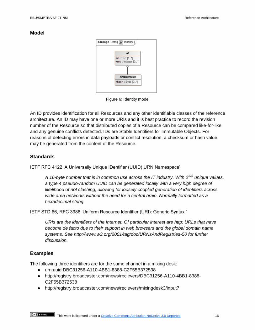
Query
Figure 12 shows an example in which a routing control panel discovers a Query Interface,
makes a one-off REST query of the available Devices, and subscription queries of the available
Senders and Receivers.
Figure 12: Query sequence
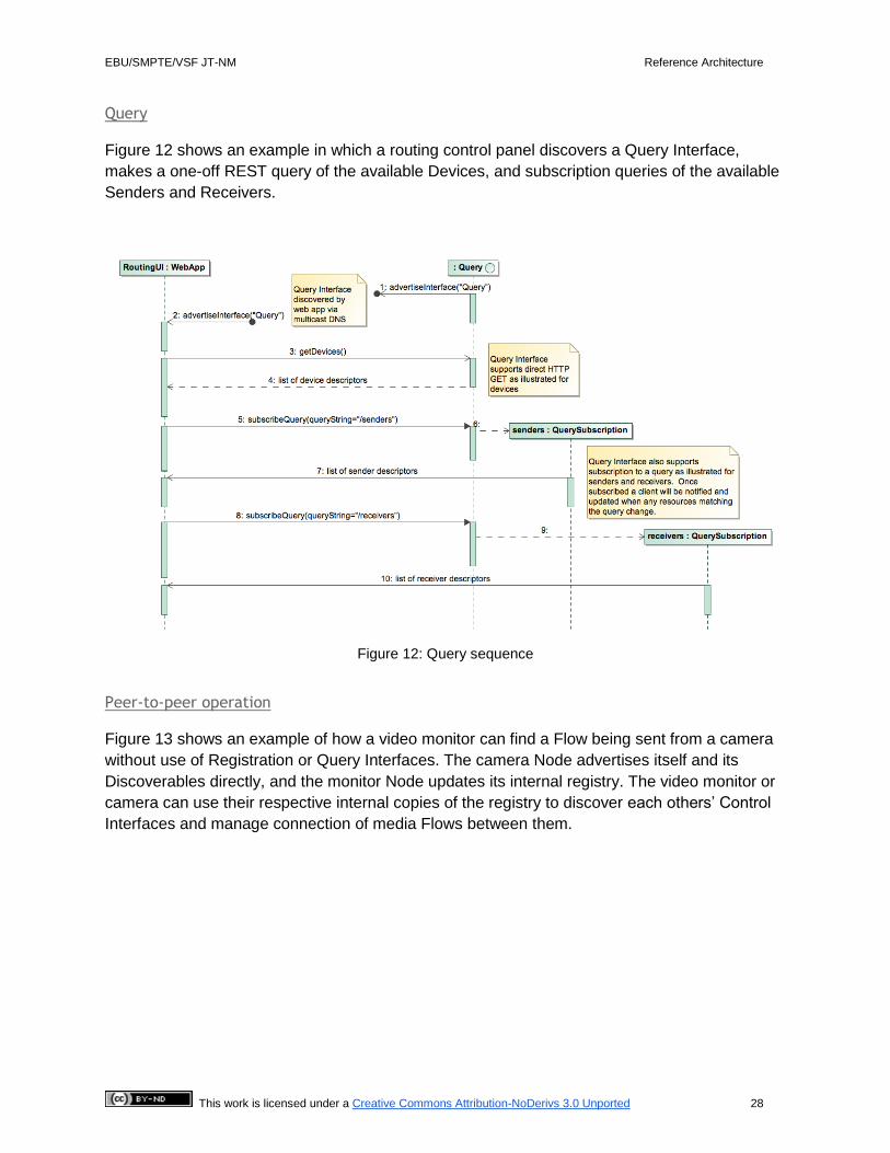
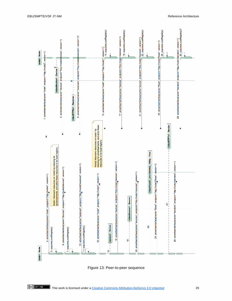
Peer-to-peer operation
Figure 13 shows an example of how a video monitor can find a Flow being sent from a camera
without use of Registration or Query Interfaces. The camera Node advertises itself and its
Discoverables directly, and the monitor Node updates its internal registry. The video monitor or
camera can use their respective internal copies of the registry to discover each others’ Control
Interfaces and manage connection of media Flows between them.
EBU/SMPTE/VSF JT-NM Reference Architecture
This work is licensed under a Creative Commons Attribution-NoDerivs 3.0 Unported 29
Figure 13: Peer-to-peer sequence
EBU/SMPTE/VSF JT-NM Reference Architecture
This work is licensed under a Creative Commons Attribution-NoDerivs 3.0 Unported 30
Other System Capabilities
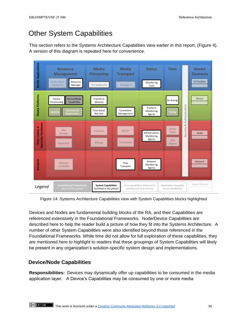
This section refers to the Systems Architecture Capabilities view earlier in this report, (Figure 4).
A version of this diagram is repeated here for convenience.
Figure 14: Systems Architecture Capabilities view with System Capabilities blocks highlighted
Devices and Nodes are fundamental building blocks of the RA, and their Capabilities are
referenced extensively in the Foundational Frameworks. Node/Device Capabilities are
described here to help the reader build a picture of how they fit into the Systems Architecture. A
number of other System Capabilities were also identified beyond those referenced in the
Foundational Frameworks. While time did not allow for full exploration of these capabilities, they
are mentioned here to highlight to readers that these groupings of System Capabilities will likely
be present in any organization’s solution-specific system design and implementations.
Device/Node Capabilities
Responsibilities: Devices may dynamically offer up capabilities to be consumed in the media
application layer. A Device’s Capabilities may be consumed by one or more media
EBU/SMPTE/VSF JT-NM Reference Architecture
This work is licensed under a Creative Commons Attribution-NoDerivs 3.0 Unported 31
applications, and as workflows change, those Capabilities may be used by an entirely different
application at a later time.
Devices may have Senders, from which they make available Flows to the Network, and/or
Receivers, which they use to consume Flows from the Network.
Devices implement Interfaces through which their Capabilities are accessed. These Interfaces
are exposed through Endpoints, to which clients can connect.
A Device may support only single Capabilities, such as ‘file retrieval’, or it might be able to
provide a set of capabilities combined together and exposed as a more complex function, such
as a video switcher performing both mixing and routing.
Devices and Nodes also provide Endpoints exposing Interfaces to report on their configuration,
status and health
Devices and Nodes can register themselves so they can be discovered.
Relationships: Devices are hosted by Nodes. Identity and registration of Nodes and Devices is
managed as part of the Identity, Discovery & Registration Frameworks and their availability is
managed through provisioning and resource management.
Device Provisioning
Responsibilities: Enables virtual Devices to be instantiated and “spun up” from a machine-
readable description.
Relationships: Service provided by a Node.
Devices may be physical boxes connected to a Network, or virtual instances provisioned onto a
Node. Provisioning is only relevant in the latter case.
Virtual Devices may have fixed or variable Capabilities, depending on their implementation.
Resource Management
Responsibilities: Tracks usage of processing and networked Resources and provides
information on Resource availability to configure clients, provide status, availability and
capability information as an aid to provisioning Devices and making connections between their
Senders and Receivers.
Relationships: Uses dynamic information provided by the monitoring services, aggregating
this with information gleaned from system configuration tools.
A Task Engine may provide intelligent provisioning behavior based on information made
available by the Resource Manager, using Provisioning services to provision Devices to Nodes
on demand to perform a Task with optimal use of system resources.

EBU/SMPTE/VSF JT-NM Reference Architecture
This work is licensed under a Creative Commons Attribution-NoDerivs 3.0 Unported 32
Flow Transformation
Responsibilities: Process Flows of Grains, performing transformation of content in specific
ways. May take single or multiple Flows as input, and produce single or multiple Flows as
outputs. Transformation Capabilities generally operate independent of Timing services and do
not modify Grain timing metadata. For timing related transformation Capabilities, see Re-timing.
Examples: encoding a video Flow, downscaling and de-interlacing a video Flow from 1080i to
720p and mixing of audio or video Flows
Relationships: Transformation Capabilities are provided by Devices (specifically Processing
Devices).
Re-timing
Responsibilities: Modify Grain timing metadata to reconcile timing at a system boundary or
between different Flows. Includes re-timing within Flows.
Examples: video frame synchronization or frame rate conversion
Relationships: Re-timing Capabilities are provided by Devices. Time-shifting of Flows (delay)
and slo-mo playback re-timing may use Flow Storage and Retrieval Capabilities.
Flow Transport
Responsibilities: Provides network carriage (aka transport) of Flows between Senders and
Receivers across the network fabric, preserving core timing and identity information.
Relationships: Routing between Senders and Receivers is managed through the Connection
Management services.
Connection Management
Responsibilities: Enable interconnection of Devices across the network. Provide mechanisms
to create connections over which Flows are transported between Senders and Receivers
belonging to different Devices.
Relationships: May use Resource Management capabilities to make decisions on whether
connections can be supported with current network loading, etc.
A special case of connection is the seamless switching between two Flows.
Connection Management may offer QoS guarantees for connections and/or make use of
distributed monitoring capabilities, depending on system implementation choices.

EBU/SMPTE/VSF JT-NM Reference Architecture
This work is licensed under a Creative Commons Attribution-NoDerivs 3.0 Unported 33
Flow Storage and Retrieval
Responsibilities: Provides persistent storage of Grains and Flows with their timing and identity
metadata intact.
Relationships: Provides low level interfaces to allow Devices to directly ‘record’ to and ‘replay’
from the store. Provides higher level interfaces to allow sequential and random access retrieval
of Grains in various forms and formats. May also provide interfaces for ingest of file-based
content.
Control Surface / UI
Responsibilities: Discover and control Devices through Capabilities exposed in the Discovery
and Registration Framework
Relationships: Uses Discovery and Registration Framework to discover Resources overall
including Nodes, Devices and their Capabilities
Distributed Monitoring
Responsibilities - Tools/applications that monitor the services and activities (such as
provisioning and connection management) across the Networked Media Platform. Tools use
interfaces provided by Devices, Nodes and network resources to interrogate and report on
Device status as well as to configure Devices. Monitoring, as an application, aggregates
information from across Resources to provide a more comprehensive view of an activity or
facility.
Responsibilities - Capabilities exposed by Resources for Monitoring: Monitoring accesses
information from Resources. This includes, for every resource, being able to determine: Who
the resource/device/service is – its name and basic resource, What it is capable of including
How it can be deployed, Where it is located in terms of network attachment, the Health of a
service including status and performance, Inspection of the services current configuration,
Configuration for/of the service.
Relationships: uses interfaces provided by Devices, Nodes and network resources to
interrogate and report on their status as well as to configure them.
Master Clock
Responsibilities: provides a common clock reference and timing services for all applications,
processes, subsystems and hardware regardless of location or locality. In the JT-NM
Reference Architecture, this is provided by a network-derived clock, as described in the Timing
Framework.
EBU/SMPTE/VSF JT-NM Reference Architecture
This work is licensed under a Creative Commons Attribution-NoDerivs 3.0 Unported 34
Relationships: This is used by the Timing Framework leveraging existing very high precision
commodity infrastructure.
Making the Reference Architecture Real
Applying a Reference Architecture is, by its very nature, something that is quite abstract, and is
something that requires additional work in order to build out into real systems. In this section,
two diagrams are provided to illustrate how one might use the Reference Architecture to begin
to build a solution-specific system design. The first shows how some familiar Devices can be
connected together, with monitoring, control, search and task management as cross-cutting
concerns. The second illustrates a process whereby an operator uses a web routing control
panel to interconnect a sender and a receiver.
Device Interconnection Illustration
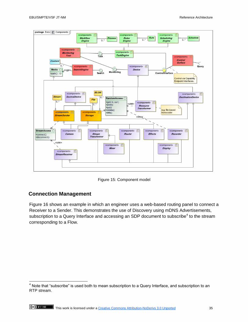
Figure 15, the example UML component diagram shows how a number of familiar Devices are
related and how they can be connected together to build a networked media facility. This
diagram shows how a common approach for monitoring, control, search and access to media
can be adopted for all Devices.
A particular benefit of this approach is that it demonstrates how the core function of a Device, its
control, monitoring and access to its content can be decomposed into separate concerns.
Constraints on the form and location of equipment that were imposed by dedicated hardware
and SDI cables can be overcome using IT technology, allowing for data-center style
deployments. Moreover, with appropriate adherence to IT standards, off-the-shelf tools for
control and monitoring, including browser-based applications, can be applied.
At the core of the model are Devices, controlled according to their Capabilities and monitored
via their Monitoring Interfaces. Some Devices are sources for content, such as a camera, and
some are destinations, such as a recorder or a display. Some are Processing Devices, such as
a vision mixer. Stream Receivers can connect and disconnect from streams provided by stream
sources through stream access interfaces. Some Devices provide storage of content through
File Systems or Object Stores. These provide a random access interface for retrieving, growing,
replacing and deleting the content. Both stream access and random access are possible by
following a path locator for the specific version of content offered by a particular device.
Other kinds of component shown include:
● task engines, with task interfaces that allow tasks to be tracked;
● search engines that can trawl content storage and track stream provision so that
users can find content via a search interface;
● Control Surfaces that control Devices via their Control Interfaces;
● Monitoring Tools that make use of the Monitoring Interfaces of Devices.
EBU/SMPTE/VSF JT-NM Reference Architecture
This work is licensed under a Creative Commons Attribution-NoDerivs 3.0 Unported 35
Figure 15: Component model
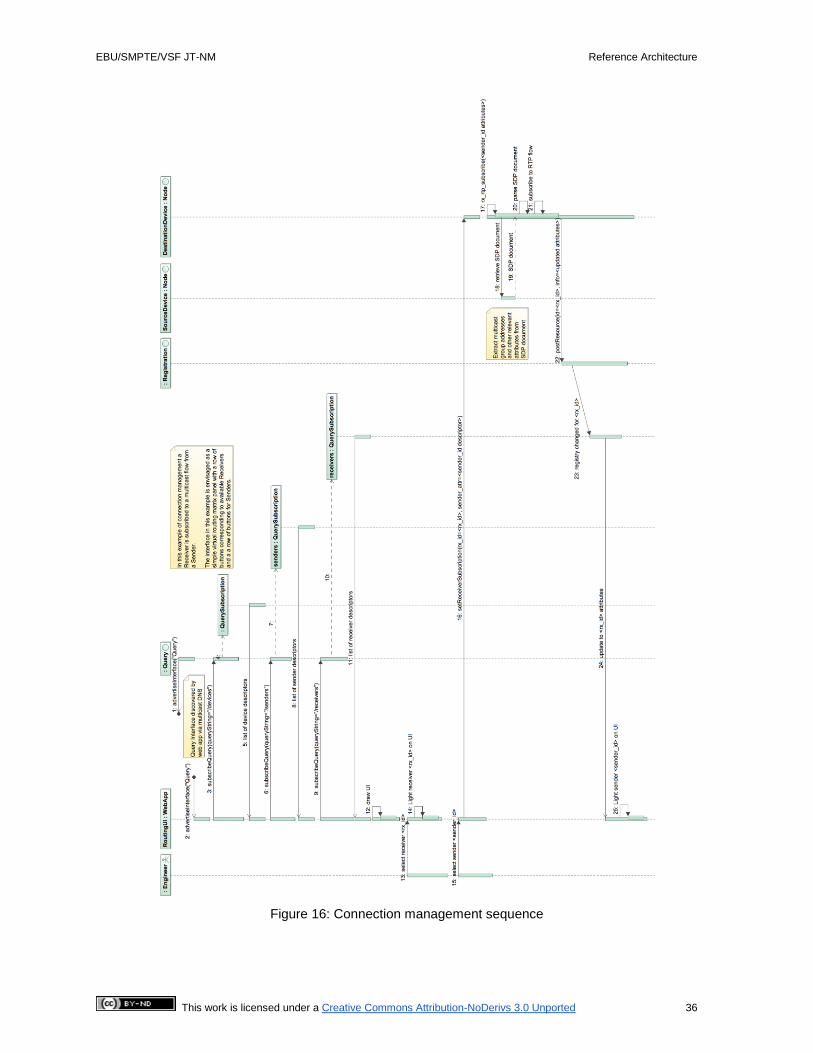
Connection Management
Figure 16 shows an example in which an engineer uses a web-based routing panel to connect a
Receiver to a Sender. This demonstrates the use of Discovery using mDNS Advertisements,
subscription to a Query Interface and accessing an SDP document to subscribe4 to the stream
corresponding to a Flow.
4 Note that “subscribe” is used both to mean subscription to a Query Interface, and subscription to an
RTP stream.
EBU/SMPTE/VSF JT-NM Reference Architecture
This work is licensed under a Creative Commons Attribution-NoDerivs 3.0 Unported 36
Figure 16: Connection management sequence

EBU/SMPTE/VSF JT-NM Reference Architecture
This work is licensed under a Creative Commons Attribution-NoDerivs 3.0 Unported 37
Appendix A - Model views
The models in Appendix A are a stable representation that will be subsequently developed
based on practical experience. While these models have not been included in the body of the
Reference Architecture, they provide a level of detail which is missing in the RA itself. It is
recognized that additional detail will be necessary in the RA if the JT-NM is to achieve its goal of
increasing the level of interoperability between professional networked media implementations.
It is anticipated that these models will prompt ongoing discussion in the industry.
Why modeling
Modeling uses a common language to represent elements of media companies in a way that is
widely understood in the IT industry. It enables JT-NM to present a reusable architectural
framework concisely as:
● a few pages of paper;
● a computer-based model that can automatically be transformed into skeleton code.
The value of these models is as much about facilitating easier dialogue between the worlds of IT
and media professionals, as it is about the user-story-derived architecture models presented.
The media-specific models are expressed as four diagrams that make use of the more general
Unified Modeling Language (UML). As the explanatory text provided with the diagrams provides
only supplementary explanation, to read and understand the meaning of the models requires an
understanding of UML. It is highly recommended that anyone who is not familiar with UML
should first read “Modeling with the Unified Modeling Language” which can be found on the
JT-NM website (http://www.jt-nm.org/articles) Further background information about the
software-only context of modern data center technologies that are the intended target for the
UML reference models can be found in a companion document, “Media Architectures fit for the
IT Data Center” at the same website.
Data Model
The JT-NM data model started life by extracting the nouns from the user stories published as
part of the first phase of the Task Force5. Subsequent analysis has been done to find the
relationships between the key terms, to merge similar concepts, to give them the same names
and to compress a relatively large number of related ideas down to a simple model. A single
page representation has great value as it can easily be digested and be the basis of
interoperability, with the inevitable consequence that a very large amount of detail has been
hidden by abstraction.
5 http://www.videoservicesforum.org/download/jtnm/User%20Requirements%20Report%20-
%20Final_with_user_stories.pdf

EBU/SMPTE/VSF JT-NM Reference Architecture
This work is licensed under a Creative Commons Attribution-NoDerivs 3.0 Unported 38
Figure 17: Data model

EBU/SMPTE/VSF JT-NM Reference Architecture
This work is licensed under a Creative Commons Attribution-NoDerivs 3.0 Unported 39
The Foundational Frameworks of Identity, Timing and Discovery & Registration Frameworks are
all consistent with this data model.
Full definitions of the core classes of this model can be found in the glossary and, where
appropriate, the relevant framework section of this document. The model is consistent with the
conceptual model presented earlier. Some classes are provided for example or informative
purposes and these are described in this section.
Products and Content
The abstract Content and Product classes of the model are informative and included here to
show the general relationship between items of business value and the networked-media
Resources that can be used to realize that value. Each business will have its own descriptive
and enterprise metadata models and the details are out of scope of JT-NM. For example, EBU
Core provides a metadata model that could be substituted here.
Content may have many versions with differing levels of quality. There are four high-level
measures of quality:
● time-domain transformed, such as chroma sub-sampling of picture data;
● frequency-domain transformed, as used by many codecs;
● raw data, such as that which comes directly from the sensor of a camera;
● pure data, where a creative idea can be captured and transported mathematically and
recreated according to the ability of the receiving device, e.g., vector graphics.
Any transformation of media may either be reversible (e.g., zip) or non-reversible (e.g., H.264).
Further constraints on quality, such as resolution or bit rate, may be represented in more
specific technical metadata associated with the content, such as the file descriptors used in
MXF files.
Transport and Storage
In many models, media is broken down into its constituent parts, such as audio and video tracks
with their associated data Essence. In this model, components or tracks are referred to as
logical Sources, with each Source realized as Flows of different qualities. In turn, each Flow
may have a number of Grains that represent an elemental unit of Essence with associated
timing information – a similar concept to the access unit wrapped in a PES packet in MPEG
standards. Grains have Grain Payloads that can be created by a suitable encoder (e.g., codec
library) and played or realized by a suitable decoder (e.g. digital TV).
Sources, Flows and Grains have unique identities consistent with the identity framework.
Further details of establishing timing relationships between Flows and Grains are provided with
the timing framework.

EBU/SMPTE/VSF JT-NM Reference Architecture
This work is licensed under a Creative Commons Attribution-NoDerivs 3.0 Unported 40
The following table defines kinds of Sources, Flows and Grains and how they are related:
Source Flow Grain Description of Grain
VideoSource VideoFlow VideoGrain Represents a practical basic unit of video such as a single frame, field or GOP.
AudioSource AudioFlow AudioGrain Represents either a group of continuous audio samples, in a format such as PCM, or an access unit of encoded samples, such as 1024 samples for AAC audio.
DataSource DataFlow DataGrain Represents non-video and non-audio time-related data that are associated with the media. See table below.
Although not an exhaustive list, the model provides further examples of a few common types of
data, as detailed in the following table.
Flow Example Data Payload
Description
DataFlow SCTETrigger /
FrameTimedEvent /
FiredEvent
Represents time-related, synchronized, supplementary data either used in production, such as position and orientation of a camera, or delivered to a downstream device to trigger a particular behavior, such as local advert insertion.
Examples:
CaptionsFlow CaptionsElement Represents a closed captions stream (subtitle stream) that can be delivered in parallel to the video and audio, allowing a user to switch on and off the display of captions in the receiver.
BurnedInFlow CaptionsElement /
FrameTimedEvent /
FiredEvent
Represents either a keyed overlay of graphics or other video material to combine with the main stream, or a set of timed instructions to equipment to produce overlays as required. The intended result is a combination of Flows before display.
DescriptiveFlow Document Represents supplementary data that may or may not be time synchronized, enabling self-describing content and/or for interactive presentation in an application (e.g., HTML 5 browser, phone/tablet app, interactive TV service).
Specific Renditions of a Source Group may be stored as, or streamed in, a packaged collection.
The Flows and Grains of each kind of Rendition can be mapped to and from other kinds of

EBU/SMPTE/VSF JT-NM Reference Architecture
This work is licensed under a Creative Commons Attribution-NoDerivs 3.0 Unported 41
container, often with no need for transformation of the Grain’s Payload. The model summarizes
these as described in the table below:
Container Medium Description
File FileSystem Storage of all the Grain Payloads required to make a Rendition in a single file, often an interleaved frame-wrapped file such as an MXF OP-1a file or an MP4/MOV file. Files are stored in a file system, such as a local hard drive or distributed shared file system.
FileList FileSystem The Grain Payloads are stored in separate files, often one file per Flow, with an additional means to bind the presentation together. Examples include AS-02 bundles and IMF packages.
BLOB (binary
large object)
ObjectStore One or more Grain Payloads are stored as binary large objects on an object store, with an additional object or database used to recreate Flows and bind the presentation together. Examples include Amazon S3 storage and OpenStack Swift.
Stream Multiplex The Grain Payloads of Flows from the same Rendition are interleaved in a stream so that they can be reproduced with a minimal amount of buffering. Multiple Renditions may be combined into a single Multiplex, for example multiple MPEG Program Streams in a MPEG Transport Stream.
Work
Work is queued and executed in a broadcast facility, with the associated kinds of task:
● Process – workflow engines execute business Processes by triggering and tracking the
activities that need to happen so as to achieve a business goal, such as transcoding and
delivering every episode of a series of TV programs to a number of origin servers.
● Rule – managed by rules engines to maintain state consistent with business policies,
such as how many geographically dispersed copies of an item of content must be
available.
● Schedule element – schedule engines make sure that content is prepared in time and
loaded onto servers ready for delivery to a pre-defined schedule, with adjustments to suit
live events as required;
All of these engines initiate Tasks that need to be executed and tracked. These Tasks make use
of the Capabilities of the available Devices using the available Content.

EBU/SMPTE/VSF JT-NM Reference Architecture
This work is licensed under a Creative Commons Attribution-NoDerivs 3.0 Unported 42
Timing model
Many different kinds of timing models exist within the media industry. Some are specific to
applications (e.g., live production, post production, scheduling) and others to technologies (e.g.,
tape-based workflows, file-based workflows, audio mixing). This timing model aims to capture
just enough about these different domains of timing that the representations can be mapped
between one another, including to the minimal model of the Timing Framework.
Figure 18: Timing model
Consider how the model maps to various different formats:
● The Minimal Timing Framework is supported, with PTP Time Stamps, the SMPTE
Epoch, nanosecond Time Bases and a PTP clock.
● Professional media files, such as MXF files, have a close relationship to their tape
predecessors with a rational Time Base and a Timecode track allowing each frame of
video to have a Time Label. The index table of an MXF file allows frames or samples to
be accessed using a zero-based index from the start of the file. Synchronized tracks in
an MXF file may be slightly offset from one another to compensate for sample groupings
EBU/SMPTE/VSF JT-NM Reference Architecture
This work is licensed under a Creative Commons Attribution-NoDerivs 3.0 Unported 43
with different Time Bases (e.g. AAC audio payloads at 48000/1024 with video at
60000/1001).
● MPEG transport streams use a 90000Hz clock to Time Stamp each access unit and
enable a decoder to synchronize streams, where an access unit is typically a frame or
group of audio samples.
Different media operations have different requirements for timing labels:
● Many sports workflows relate time-of-day to Timecode so that the wall clock time of an
event, such as a goal in soccer, matches the labelled time.
● A drama may have a relationship between elapsed program time and a script, e.g. the
show “24”.
● Multi-camera live studio workflows may use a timing reference to synchronize frame
outputs.
● Playout operations may expect all delivered programs and/or their segments to start
from a given Timecode, such as 10:00:00:00.
Networked media resource dynamics
Networked media physical and virtual infrastructure will always be in a state of change as it
dynamically adjusts to agile requirements. This includes:
● The concept of Devices providing their Capabilities for runtime discovery and use has
been introduced in the Discovery & Registration Framework.
● Before this is possible, Nodes have to be configured and connected to Networks,
possibly more than one network at a time.
● Devices are deployed onto Nodes. A virtual Device may require some static
Configuration as part of this process, or may expose every aspect of its Configuration via
a Capability, such as the use of the Amazon EC2 API to start a virtual machine in the
cloud.

EBU/SMPTE/VSF JT-NM Reference Architecture
This work is licensed under a Creative Commons Attribution-NoDerivs 3.0 Unported 44
Figure 19: Networked media resource dynamics model
To support discovery and registration, Nodes must be attached to at least one or more
Bidirectional Networks. Nodes may also be attached to Unidirectional Networks at the edge,
such as bookable long distant circuits (e.g., satellite circuit), but the Capabilities offered by the
circuits must be discovered, configured and monitored via a Bidirectional Network. Through a
Node’s Configuration, the system may be aware of Unidirectional Networks or other signals.
Capabilities may be parameterized using a rich and extensible library of parameter types,
although this is to be determined fully in future work. For example, such a type may represent a
fader control on a mixing desk or the array of record and playback buttons on a camera.
Nodes and Devices can be monitored for their performance, system health and reported faults
through Monitoring Interfaces.

EBU/SMPTE/VSF JT-NM Reference Architecture
This work is licensed under a Creative Commons Attribution-NoDerivs 3.0 Unported 45
Appendix B - Glossary of terms
Note: Some defined terms appear in the UML models and conceptual model with spaces removed, as is a convention
or even a necessity when formatting literals in computer code. Defined terms with spaces and model elements
without spaces refer to the same term. For example, “TimeBase” in the model is the same as “Time Base” in the
glossary and text of this document.
Advertisement: A network announcement of an Interface (including Registration, Query, and
Node Interfaces) or a Discoverable
This is one mechanism to allow Devices and clients to discover the Interface and resolve its Endpoint.
Advertisements of Discoverables are used for peer-to-peer discovery.
Bidirectional Network: A Network that allows information to pass both into and out of a Node
Although a Node could stream onto a Unidirectional network, a Bidirectional network is needed to support
Discovery & Registration and management of its Devices.
Capability: a representation of a “usefully minimal” item of functionality provided by a Device,
providing just enough information for an application to be suitably paired with the Device
Examples of Capabilities could include: o Decode a particular Essence compression format
o Support changes of frame rate (for the output of a Source Device or Processing Device)
o Playback a stored Flow
o Set encoding parameters
o Position an on-screen graphic
Each Capability is read-only; its meaning is fixed for the lifetime of the Device. However, as in the “set
encoding parameters” example above, a Capability may be realized through writable parameters. Also, a
Device may add or remove Capabilities during its lifetime.
Clock: a networked component providing a ubiquitous time reference
Configuration: A static collection of values for parameters those are required when a Node or
Device is provisioned
Examples of configuration parameters include: o IP address and hostname of a node;
o Setting a camera to NTSC or PAL mode.
Content: Essence that adds value to an organization
Control Interface: an Interface that allows control of the operation and parameters of a Device
Control Surface: a user interface on a client that accesses one or more Control Interfaces
Destination Device: A Device that has at least one Receiver, i.e. it has input(s)
A video monitor is an example of a Destination Device.

EBU/SMPTE/VSF JT-NM Reference Architecture
This work is licensed under a Creative Commons Attribution-NoDerivs 3.0 Unported 46
Device: a logical block of functionality within a networked media infrastructure
Example of Devices could include: o Camera
o SDI to IP adapter
o Chroma keyer
o Audio mixer
A Device may have a permanent presence on its Node (Fixed Device, e.g., a networked camera), or it may
be created on demand by its Node (Virtual Device, e.g., a software-based transcoder). Nodes may
dynamically create different types of Device (Dynamic Device).
Discoverable: something that can be discovered and registered. Examples include: Device,
Node, Capability, Source, Flow, Sender and Receiver
A Discoverable has a unique identifier and other useful information (e.g. a human-readable label).
Endpoint: the network entry point to a running instance of an Interface
Epoch: identifies the zero value of a Clock
Essence: video, audio or data, typically intended for consumption
Example of Essence could include: o The video portion of a program
o The audio portion of a program
o Time-synchronized metadata for subtitles or closed captioning
Flow: a sequence of Grains from a Source; a concrete representation of content emanating
from the Source
For example, sequences of Grains formed from Raw, JPEG2000 and AVC-I encodings of the same video
content are Flows of the same Source
GOP: A Group of Pictures that is a bounded succession of frames within a coded video stream.
In many streaming applications, each GOP provides a clean random access point from where
decoders can start playing video.
Grain: represents an element of Essence or other data associated with a specific time, such as
a frame, or a group of consecutive audio samples, or captions
Grain Payload: The element of Essence or other data within a Grain
ID: A Stable Identifier for Immutable Objects consisting of at least one Unique Resource
Identifier, with an optional revision number to track updates. Provides the type for all identifiers
that are properties of the classes of JT-NM model
ID With Hash: A kind of revision-specific identifier that includes a hash value of the value it
identifies, used to detect and assist with conflict resolution on the update of values across
distributed networks

EBU/SMPTE/VSF JT-NM Reference Architecture
This work is licensed under a Creative Commons Attribution-NoDerivs 3.0 Unported 47
Immutable Object: A Resource whose state cannot be altered after it is created. If the
Resource is changed (i.e. mutated) in any way, it is considered as a new revision of that
Resource with an updated revision number component of its unique ID
Interface: provides a specified access to some functionality over a network. May be advertised
for discovery purposes
Media: Audio, video, and other means to carry general communication, information, or
entertainment
Monitoring Interface: an Interface allowing a Monitoring Tool to obtain information about the
status of a Device
Monitoring Tool: a tool used to obtain information about the status of Devices
Network: Infrastructure for the interconnection of Nodes
Node: a logical host, acting as a container of one or more Devices
A Node may have a permanent physical presence, or may be created on demand, for example as a virtual
machine in a cluster or cloud.
Node Interface: a Node provides this Interface to list the Devices and associated Discoverables
hosted on it
Processing Device: A Device that has at least one Sender and at least one Receiver, i.e. it has
input(s) and output(s)
A transcoder is an example of a Processing Device.
Query Interface: an Interface that allows an application to:
o retrieve representations of registered Discoverables
o subscribe to registrations or de-registrations of Discoverables
o A Query Interface may allow filtering.
Receiver: consumes a Flow from a Sender
A Receiver could be considered as a “virtual input port” on the Device.
Registration Interface: an Interface that allows a Node to register and de-register its
Discoverables with a Registry
Registry: a component that holds information about the Discoverables present on the network
Rendition: A collection of time-synchronized Flows intended for simultaneous presentation,
providing a complete experience of a Source Group. Renditions can be stored or streamed.
For example, a representation of a source group consisting of low bitrate video (H.264 at 2Mbps),
compressed audio (AAC) and closed captions (timed text) intended for consumption on a mobile phone.
Higher bitrate versions of the source group may be available for presentation on HD televisions etc.

EBU/SMPTE/VSF JT-NM Reference Architecture
This work is licensed under a Creative Commons Attribution-NoDerivs 3.0 Unported 48
Resource: An addressable part or element of any system with a unique ID
All addressable instances of classes in the JT-NM models are Resources, including Discoverables, Content,
Tasks, Files, and Streams.
Sender: makes a Flow available on the network
A Sender could be considered as a “virtual output port” on the Device.
Source: an abstract concept that represents the primary origin of a Flow or set of Flows
A Device may provide several Sources e.g. a video camera has separate video and audio sources
Source Device: A Device that has at least one Sender, i.e. it has output(s)
A camera is an example of a Source Device.
Stable Identifier: Identifier that persists from its creation both during and beyond the lifetime of
the identified Resource. The identifier is not subsequently reused
Synchronization: The ability for media processing systems to determine which grains are
intended for simultaneous presentation
Time Base: specifies the units used for measuring time. Expressed as a rational (or integer)
number of units per second.
Timecode: a representation of a time within a video with a precision of frames. The Epoch of
Timecode is often implementation-specific. When used with fractional frame rates, some
Timecode values may be skipped to maintain long-term alignment with the frame cadence (this
is known as “dropFrame” Timecode).
Time Label: a representation of time as a count at a media-related Time Base (e.g., video
frame rate)
Time Stamp: an absolute time (that is, an offset from the start of an Epoch) describing the
relationship of a Grain with a Clock
Unidirectional Network: A Network that only supports information flow into, or out of, a Node.
Wall Clock Time: a representation of a specific time in a specific time zone.

EBU/SMPTE/VSF JT-NM Reference Architecture
This work is licensed under a Creative Commons Attribution-NoDerivs 3.0 Unported 49
Acknowledgements
The JT-NM reflector comprises more than 300 participants from 175 organizations.
The JT-NM administrative group would like to thank all the participants who contributed their
thoughts over the past months in multiple meetings and teleconferences. This work has been
compiled and the technical contributions have been synthesized into this report by the following
authors:
Peter Brightwell – BBC Research & Development, Dr. Richard Cartwright – Quantel, Thomas
Edwards – Fox, Richard Friedel – Fox, Janet Gardner – Perspective Media Group, Brad Gilmer
– Gilmer & Associates, Chuck Meyer – Grass Valley, Carl Ostrom – System Resource, Felix
Poulin – EBU, Dr. Karl Schubert – Technova Consulting, Robert Wadge – BBC Research &
Development


![interoperability.blob.core.windows.netinteroperability.blob.core.windows.net/...150904.docx · Web view[MS-ABS]: Address Book File Structure. Intellectual Property Rights Notice](https://static.documents.pub/doc/80x56/5a7c76517f8b9ae9398cde0d/viewms-abs-address-book-file-structure-intellectual-property-rights-notice-for.jpg)


