arXiv:2007.08380v1 [eess.SP] 16 Jul 2020 1 Joint Trajectory and Passive Beamforming Design for Intelligent Reflecting Surface-Aided UAV Communications: A Deep Reinforcement Learning Approach Liang Wang, Kezhi Wang, Cunhua Pan, Wei Xu and Nauman Aslam Abstract—In this paper, the intelligent reflecting surface (IRS)- assisted unmanned aerial vehicle (UAV) communication system is studied, where an UAV is deployed to serve the user equipments (UEs) with the assistance of multiple IRSs mounted on several buildings to enhance the communication quality between UAV and UEs. We aim to maximize the overall weighted data rate and geographical fairness of all the UEs via jointly optimizing the UAV’s trajectory and the phase shifts of reflecting elements of IRSs. Since the system is complex and the environment is dynamic, it is challenging to derive low-complexity algorithms by using conventional optimization methods. To address this issue, we first propose a deep Q-network (DQN)-based low-complex solution by discretizing the trajectory and phase shift, which is suitable for practical systems with discrete phase-shift control. Furthermore, we propose a deep deterministic policy gradient (DDPG)-based solution to tackle the case with continuous trajec- tory and phase shift design. The experimental results prove that the proposed solutions achieve better performance compared to other traditional benchmarks. Index Terms—Deep Reinforcement Learning, UAV communi- cations, Reconfigurable Intelligent Surface, Intelligent Reflecting Surface. I. I NTRODUCTION In the fifth-generation (5G) wireless networks and beyond, it is widely envisioned that it will achieve 1000-fold increase in network capacity, accommodate at least 100 billion connected devices and support a number of emerging applications such as virtual reality (VR) and augmented reality (AR). To satisfy this ever-increasing demand, unmanned aerial vehicle (UAV) is regarded as one of the most promising technologies to achieve these ambitious goals. Compared to the traditional communication systems that utilize the terrestrial fixed base stations, UAV-aided communication systems are more cost- effective and likely to achieve better quality of service (QoS) due to its appealing properties of flexible deployment, fully controllable mobility and low cost. In fact, with the assistance of UAVs, the system performance (e.g., data rate and latency) Liang Wang, Kezhi Wang and Nauman Aslam are with the Department of Computer and Information Science, Northumbria University, Newcas- tle upon Tyne, NE1 8ST, U.K., emails: {liang.wang, kezhi.wang, nau- man.aslam}@northumbria.ac.uk. Cunhua Pan is with School of Electronic Engineering and Computer Science, Queen Mary University of London, E1 4NS, U.K., email: [email protected]. Wei Xu is with National Mobile Communications Research Lab, Southeast University, 210096, China, email: [email protected]. can be significantly enhanced by establishing the line-of-sight (LoS) communication links between UAVs and user equip- ments (UEs). In addition, through dynamically adjusting the flying state, UAVs are capable of improving communication performance in wireless communications. To further improve the channel quality, adaptive communications can be designed through the mobility control of the UAV systems. In order to fully exploit the potential of UAV-assisted com- munications, it is crucial to design appropriate path planning and trajectory of UAVs [1]. In [2], Hourani et al. proposed an analytical approach for optimizing the altitude of UAV for the purpose of maximizing the radio coverage on the ground. In [3], a practical scenario of UAVs in an OFDMA system was investigated, and Wu et al. proposed an iterative block coordinate descent approach for optimizing the UAV’s trajec- tory and OFDMA resource allocation, aiming to maximize the minimum average throughput of UEs. The optimization problemof UAV placement and transmit power in UAV-aided relay systems was studied in [4], where Ren et al. proposed a low-complexity iterative algorithm to solve the problem both in the free-space channel and three-dimensional channel scenarios. In [5], to minimize the energy consumption of UAV, Zeng et al. formulated a travelling sale problem and proposed an efficient algorithm to optimize the UAV trajectory, includ- ing the hovering locations and duration. Another category of UAV-assisted communication that considers a fixed-wing UAV was studied in [6], where the UAV usually applies higher speed and heavier payload and fly in the forward motion. The authors of [6] optimized the speed, direction, and acceleration of the UAV for maximizing the energy efficiency. In [7], a multi UAV-assisted communication system was studied. The authors proposed a DRL-EC 3 algorithm to optimize the UAVs’ trajectory for maximizing the energy efficiency of UAVs. Other contributions of UAV include its applications in mobile edge computing (MEC) [8], device-to-device communication [9], data collection [10], mobile crowd sensing [11] and wireless power transfer networks [12]. In [8], Yang et al. studied the power minimization problem in a multi UAV-enabled MEC system, where they proposed a low complexity algorithm for optimizing the user association, power control, computation capacity allocation and location planning. In [9], Huang et al. investigated the D2D rate maximization problem in UAV- aided wireless communication systems, where they proposed an iterative algorithm for optimizing the UAV flying altitude,
Abstract—In this paper, the intelligent reflecting surface (IRS)-assisted unmanned aerial vehicle (UAV) communication system isstudied, where an UAV is deployed to serve the user equipments(UEs) with the assistance of multiple IRSs mounted on severalbuildings to enhance the communication quality between UAVand UEs. We aim to maximize the overall weighted data rateand geographical fairness of all the UEs via jointly optimizingthe UAV’s trajectory and the phase shifts of reflecting elementsof IRSs. Since the system is complex and the environment isdynamic, it is challenging to derive low-complexity algorithms byusing conventional optimization methods. To address this issue,we first propose a deep Q-network (DQN)-based low-complexsolution by discretizing the trajectory and phase shift, which issuitable for practical systems with discrete phase-shift control.Furthermore, we propose a deep deterministic policy gradient(DDPG)-based solution to tackle the case with continuous trajec-tory and phase shift design. The experimental results prove thatthe proposed solutions achieve better performance compared toother traditional benchmarks.
In the fifth-generation (5G) wireless networks and beyond, it
is widely envisioned that it will achieve 1000-fold increase in
network capacity, accommodate at least 100 billion connected
devices and support a number of emerging applications such
as virtual reality (VR) and augmented reality (AR). To satisfy
this ever-increasing demand, unmanned aerial vehicle (UAV)
is regarded as one of the most promising technologies to
achieve these ambitious goals. Compared to the traditional
communication systems that utilize the terrestrial fixed base
stations, UAV-aided communication systems are more cost-
effective and likely to achieve better quality of service (QoS)
due to its appealing properties of flexible deployment, fully
controllable mobility and low cost. In fact, with the assistance
of UAVs, the system performance (e.g., data rate and latency)
Liang Wang, Kezhi Wang and Nauman Aslam are with the Departmentof Computer and Information Science, Northumbria University, Newcas-tle upon Tyne, NE1 8ST, U.K., emails: {liang.wang, kezhi.wang, nau-man.aslam}@northumbria.ac.uk.
Cunhua Pan is with School of Electronic Engineering and ComputerScience, Queen Mary University of London, E1 4NS, U.K., email:[email protected].
Wei Xu is with National Mobile Communications Research Lab, SoutheastUniversity, 210096, China, email: [email protected].
can be significantly enhanced by establishing the line-of-sight
(LoS) communication links between UAVs and user equip-
ments (UEs). In addition, through dynamically adjusting the
flying state, UAVs are capable of improving communication
performance in wireless communications. To further improve
the channel quality, adaptive communications can be designed
through the mobility control of the UAV systems.
In order to fully exploit the potential of UAV-assisted com-
munications, it is crucial to design appropriate path planning
and trajectory of UAVs [1]. In [2], Hourani et al. proposed
an analytical approach for optimizing the altitude of UAV for
the purpose of maximizing the radio coverage on the ground.
In [3], a practical scenario of UAVs in an OFDMA system
was investigated, and Wu et al. proposed an iterative block
coordinate descent approach for optimizing the UAV’s trajec-
tory and OFDMA resource allocation, aiming to maximize
the minimum average throughput of UEs. The optimization
problem of UAV placement and transmit power in UAV-aided
relay systems was studied in [4], where Ren et al. proposed
a low-complexity iterative algorithm to solve the problem
both in the free-space channel and three-dimensional channel
scenarios. In [5], to minimize the energy consumption of UAV,
Zeng et al. formulated a travelling sale problem and proposed
an efficient algorithm to optimize the UAV trajectory, includ-
ing the hovering locations and duration. Another category of
UAV-assisted communication that considers a fixed-wing UAV
was studied in [6], where the UAV usually applies higher speed
and heavier payload and fly in the forward motion. The authors
of [6] optimized the speed, direction, and acceleration of the
UAV for maximizing the energy efficiency. In [7], a multi
UAV-assisted communication system was studied. The authors
proposed a DRL-EC3 algorithm to optimize the UAVs’
trajectory for maximizing the energy efficiency of UAVs. Other
contributions of UAV include its applications in mobile edge
computing (MEC) [8], device-to-device communication [9],
data collection [10], mobile crowd sensing [11] and wireless
power transfer networks [12]. In [8], Yang et al. studied the
power minimization problem in a multi UAV-enabled MEC
system, where they proposed a low complexity algorithm for
optimizing the user association, power control, computation
capacity allocation and location planning. In [9], Huang et
al. investigated the D2D rate maximization problem in UAV-
aided wireless communication systems, where they proposed
an iterative algorithm for optimizing the UAV flying altitude,
has been proposed and received considerable attention in both
academia and industry, which has the potential to improve the
communication quality by installing IRSs on the wall of the
buildings. In general, the IRS consists of an array of low-
cost and passive reflecting elements, each of which is able to
reflect the incident signals by smartly adjusting the phase shift,
which has the potential to improve the achievable data rate
significantly [15]. Furthermore, since the reflecting elements
of the IRS are usually passive and thus reflect signals without
any signal processing tasks, the IRS is more energy-efficient
than traditional relay-aided communication techniques, such
as [16]. In addition, as the reflecting elements of IRS are
reconfigurable in real time, the IRS can be viewed as a feasible
transmission medium and widely deployed in the buildings and
walls.
Due to the above advantages, the IRS was extensively in-
vestigated in various wireless communication systems. In [17],
an IRS-enhanced MISO wireless system was studied, and
the authors proposed a semidefinite relaxation (SDR) based
algorithm for optimizing the active and passive beamforming,
aiming to maximize the overall received signal power at the
user. In [18], Yang et al. studied a realistic IRS-enhanced
OFDM system, where the frequency-selective channels were
considered, and the passive array reflecting coefficients were
optimized for maximizing the achievable rate of the user. For
multi-user communication systems, Huang et al. [19] inves-
tigated the energy efficiency maximization problem, and they
proposed a sequential fractional programming based algorithm
for optimizing the IRS phase shifts, which has 300% higher
energy efficiency compared with the existing benchmarks. In
order to enhance the physical layer security of IRS-aided
communication systems, Yu et al. [20] jointly optimized the
beamforming at the transmitter and the phase shifts of the IRS,
maximizing the physical layer security data rate. For multicast
scenarios, the authors in [21] investigated the downlink IRS-
aided multigroup multicast communication system, where the
IRS can be deployed to enhance the worst-case user channel
condition. In [22], Pan et al. studied the weighted sum rate
(WSR) maximization problem for an IRS-assisted multicell
MIMO communication system, and the authors proposed a
pair of algorithms named Majorization-Minimization (MM)
and Complex Circle Manifold (CCM) for optimizing the
phase shifts of the IRS. The simulation results in [22] shows
that the IRS is very effective in mitigating the cell-edge
interference. Additionally, the authors in [23] considered to
deploy an IRS in a simultaneous wireless information and
power transfer (SWIPT) system to enhance both the energy
harvesting and data rate performance. In [24], the IRS was
shown to be beneficial in reducing the latency of the mobile
edge computing system.
In [25], the authors studied the resource allocation for a
point-to-point IRS-aided MIMO communication system when
taking into account the channel estimation and channel feed-
back overhead. In [26], the globally optimal active and pas-
sive beamforming is obtained through the branch-and-bound
algorithm for a single-user IRS-aided MISO system. In [27],
the deep reinforcement learning was adopted to solve the joint
transmit beamforming matrix at the base station and the phase
shift matrix at the RIS.
Most recently, the integration of IRS in UAV-assisted
communication systems is becoming a hot research topic,
and the key challenge is to tackle the joint UAV trajectory
and passive beamforming optimization problem. In [28], the
authors considered a downlink transmission system, consisting
of a rotary-wing UAV, a ground user and an IRS. In this
work, the authors proposed a successive convex approximation
(SCA) based algorithm to optimize the UAV trajectory and
passive beamforming of the IRS. In [29], the potential of IRS
in UAV-assisted communication systems was investigated. The
authors concluded that the deployment of IRS is capable of
achieving significant performance gain in UAV-assisted cellu-
lar networks. However, most of existing algorithms are based
on convex optimization theory, which could only achieve sub-
optimal or near-optimal performance and is time-consuming
due to the fact that a number of iterations are required for
the convergence of the algorithm. Their complexity increases
drastically with the number of reflecting elements, UAVs and
IRSs.
Thanks to the advances in the field of machine learning,
most of sophisticated optimization problems can be solved
efficiently and can be deployed in real time. As a branch of
machine learning algorithm, reinforcement learning (RL) is
viewed as a useful approach for tackling complicated control
tasks, such as robotics and games. In [30], Sutton et al.
proposed a widely used model-free RL algorithm named Q-
learning, where some fundamental knowledge, such as agent,
environment, state, action, reward and Q-value were intro-
duced. In addition, another mechanism named Q-table was
employed in Q-learning. However, as the size of Q-table is
finite, Q-learning can only handle control problems in discrete
state and action spaces. As an extension of Q-learning, Mnih et
al. [31] proposed the deep Q-network (DQN) algorithm, which
combines RL and the powerful deep neural network (DNN).
3
Additionally, two techniques named experience replay and tar-
get network were integrated. The experimental results proved
that DQN is capable of achieving enhanced performance in
the challenging Atari 2600 games. In DQN, the Q-table is
replaced by the DNN, as DQN can handle the control problem
with infinite state spaces. However, the action space of DQN
is still discrete. Inspired by DQN, Silver et al. proposed a deep
deterministic policy gradient (DDPG) [32] algorithm based on
the actor-critic [33] method, which is able to be applied to
continuous action spaces.
Against the above background, we propose an IRS-aided
UAV system where the UAV is deployed to provide commu-
nication services to the ground UEs. To enhance the channel
condition between UAV and UEs, which may be blocked by
some obstacles such as high buildings, IRS is proposed to be
mounted on the exterior wall of the buildings. We aim to max-
imize the overall weighted data rate and geographical fairness
of all the UEs via jointly optimizing the UAV’s trajectory and
the phase shifts of the reflecting elements of IRSs. To address
this problem, firstly, we propose a deep Q-network (DQN)-
based low-complex solution by discretizing the trajectory and
phase shift, which can be useful for practical systems with
discrete phase-shift control. Then, we further propose a deep
deterministic policy gradient (DDPG)-based solution to tackle
the continuous counterpart. The experiment verifies that the
proposed algorithms achieve better performance compared to
other traditional benchmarks.
The reminder of this paper is organized as follows. In
Section II, we describe the system model, including the
optimization problem. In Section III, we present the proposed
DQN and DDPG algorithms. In Section IV, the experimental
results are analyzed. Finally, we conclude the paper in Section
V. In addition, the main notations used in this paper are
summarized in Table. I.
Other Notations: In this paper, CM×1 denotes the set of
M × 1 complex vectors. diag{·} denotes the diagonalization
operation. (·)H denotes the conjugate transpose operation. E[·]denotes the expectation operation. | · | denotes the determinant
operation.
II. SYSTEM MODEL
Assume that there is one rotary UAV, K IRSs mounted on
K buildings respectively and N UEs to be served, as shown
in Fig. 1. We assume that the UAV serves all the UEs via the
downlink transmission system. Also, assume that the UEs are
located in the crowded area where they suffer from severe path
loss and high attenuation, caused by tall buildings and trees.
IRSs are deployed for enhancing the communication quality
of UEs. As shown in Fig.1, the UAV flies at a fixed altitude
HU (in meters) over a rectangle target area with side lengths
[Xmax, Y max] for a certain period of time T all. We denote
the set of IRSs as K , {k = 1, 2, ...,K} and the set of
UEs as N , {n = 1, 2, ..., N}. For simplicity, we divide
T all into T time slots (TSs), each of which has the maximal
time duration T d. Also, the set of TSs is denoted as T ,
{1, 2, ...T }. Additionally, each IRS is equipped with a uniform
linear array (ULA) with M reflecting elements, which could
TABLE I: Main Notations.
Notation Definition
k,K,K the index, the number, and the set of IRSs
n,N,N the index, the number, and the set of UEs
t, T, T the index, the number, and the set of TSs
mk ,Mk the index, the set of reflecting elements of IRS kM the number reflecting elements of each IRS
µt, dt flying angle, distance of UAV in TS t[XU
0, Y U
0, HU ] coordinates of UAV in the initial TS
[XUt , Y U
t , HU ] coordinates of UAV in TS tXmax, Y max side length of the target area
vt velocity of UAV in TS tT d time duration of each TS
dmax maximal flying distance of UAV in each TS
Ur tip speed of the rotor blade
Vh mean rotor induced velocity when hovering
d0 main body drag ratio
ρa air density
z rotor solidity
A the rotor disc area
et remaining energy level of UAV in TS temax maximal energy level of UAV
[XIk, Y I
k, HI
k] coordinates of IRS k
[xn, yn] coordinates of UE ndUIk,t
distance between UAV and IRS k in TS t
dIEn,k
distance between IRS k and UE n
hUIk,t
channel gain between UAV and IRS k in TS t
hUIt overall channel gain between UAV and IRSs in TS t
hIEn,k
channel gain between IRS k and UE n in TS t
hIEn overall channel gain between IRSs and UE n
Rn,t data rate of UE n to in TS tσ2 noise variance
P transmit power of UAV
cn,t serving status of UE n in TS tki, kq weight factors
γ discount factor
st, at, rt state, action, reward in TS tp penalty
n
t
hIE
n,k
hUI
k,t
X
Z
Yk
Fig. 1: Architecture of IRS-assisted UAV communication
system
4
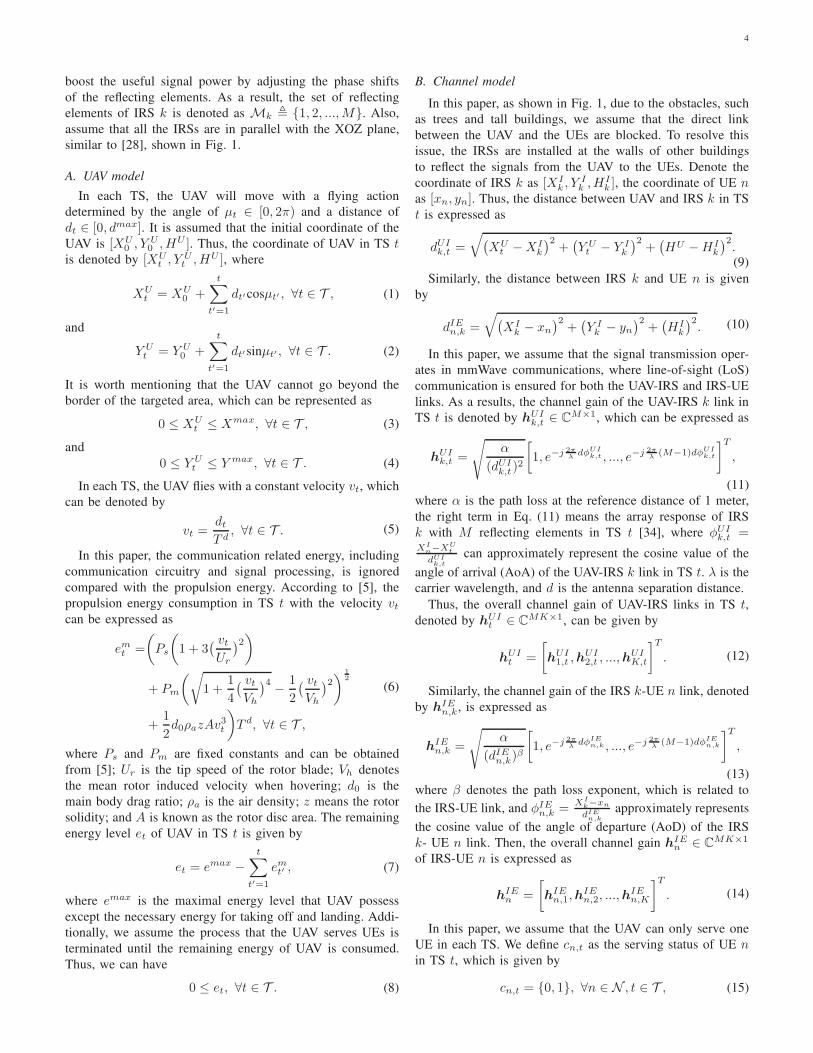
boost the useful signal power by adjusting the phase shifts
of the reflecting elements. As a result, the set of reflecting
elements of IRS k is denoted as Mk , {1, 2, ...,M}. Also,
assume that all the IRSs are in parallel with the XOZ plane,
similar to [28], shown in Fig. 1.
A. UAV model
In each TS, the UAV will move with a flying action
determined by the angle of µt ∈ [0, 2π) and a distance of
dt ∈ [0, dmax]. It is assumed that the initial coordinate of the
UAV is [XU0 , Y U
0 , HU ]. Thus, the coordinate of UAV in TS t
is denoted by [XUt , Y U
t , HU ], where
XUt = XU
0 +
t∑
t′=1
dt′cosµt′ , ∀t ∈ T , (1)
and
Y Ut = Y U
0 +t
∑
t′=1
dt′sinµt′ , ∀t ∈ T . (2)
It is worth mentioning that the UAV cannot go beyond the
border of the targeted area, which can be represented as
0 ≤ XUt ≤ Xmax, ∀t ∈ T , (3)
and
0 ≤ Y Ut ≤ Y max, ∀t ∈ T . (4)
In each TS, the UAV flies with a constant velocity vt, which
can be denoted by
vt =dt
T d, ∀t ∈ T . (5)
In this paper, the communication related energy, including
communication circuitry and signal processing, is ignored
compared with the propulsion energy. According to [5], the
propulsion energy consumption in TS t with the velocity vtcan be expressed as
emt =
(
Ps
(
1 + 3( vt
Ur
)2)
+ Pm
(√
1 +1
4
( vt
Vh
)4−
1
2
( vt
Vh
)2)
1
2
+1
2d0ρazAv
3t
)
T d, ∀t ∈ T ,
(6)
where Ps and Pm are fixed constants and can be obtained
from [5]; Ur is the tip speed of the rotor blade; Vh denotes
the mean rotor induced velocity when hovering; d0 is the
main body drag ratio; ρa is the air density; z means the rotor
solidity; and A is known as the rotor disc area. The remaining
energy level et of UAV in TS t is given by
et = emax −t
∑
t′=1
emt′ , (7)
where emax is the maximal energy level that UAV possess
except the necessary energy for taking off and landing. Addi-
tionally, we assume the process that the UAV serves UEs is
terminated until the remaining energy of UAV is consumed.
Thus, we can have
0 ≤ et, ∀t ∈ T . (8)
B. Channel model
In this paper, as shown in Fig. 1, due to the obstacles, such
as trees and tall buildings, we assume that the direct link
between the UAV and the UEs are blocked. To resolve this
issue, the IRSs are installed at the walls of other buildings
to reflect the signals from the UAV to the UEs. Denote the
coordinate of IRS k as [XIk , Y
Ik , H
Ik ], the coordinate of UE n
as [xn, yn]. Thus, the distance between UAV and IRS k in TS
t is expressed as
dUIk,t =
√
(
XUt −XI
k
)2+(
Y Ut − Y I
k
)2+(
HU −HIk
)2.(9)
Similarly, the distance between IRS k and UE n is given
by
dIEn,k =
√
(
XIk − xn
)2+(
Y Ik − yn
)2+(
HIk
)2. (10)
In this paper, we assume that the signal transmission oper-
ates in mmWave communications, where line-of-sight (LoS)
communication is ensured for both the UAV-IRS and IRS-UE
links. As a results, the channel gain of the UAV-IRS k link in
TS t is denoted by hUIk,t ∈ CM×1, which can be expressed as
hUIk,t =
√
α
(dUIk,t)
2
[
1, e−j 2πλ
dφUIk,t , ..., e−j 2π
λ(M−1)dφUI
k,t
]T
,
(11)
where α is the path loss at the reference distance of 1 meter,
the right term in Eq. (11) means the array response of IRS
k with M reflecting elements in TS t [34], where φUIk,t =
XIn−XU
t
dUIk,t
can approximately represent the cosine value of the
angle of arrival (AoA) of the UAV-IRS k link in TS t. λ is the
carrier wavelength, and d is the antenna separation distance.
Thus, the overall channel gain of UAV-IRS links in TS t,
denoted by hUIt ∈ CMK×1, can be given by
hUIt =
[
hUI1,t ,h
UI2,t , ...,h
UIK,t
]T
. (12)
Similarly, the channel gain of the IRS k-UE n link, denoted
by hIEn,k, is expressed as
hIEn,k =
√
α
(dIEn,k)β
[
1, e−j 2πλ
dφIEn,k , ..., e−j 2π
λ(M−1)dφIE
n,k
]T
,
(13)
where β denotes the path loss exponent, which is related to
the IRS-UE link, and φIEn,k =
XIk−xn
dIEn,k
approximately represents
the cosine value of the angle of departure (AoD) of the IRS
k- UE n link. Then, the overall channel gain hIEn ∈ CMK×1
of IRS-UE n is expressed as
hIEn =
[
hIEn,1,h
IEn,2, ...,h
IEn,K
]T
. (14)
In this paper, we assume that the UAV can only serve one
UE in each TS. We define cn,t as the serving status of UE n
in TS t, which is given by
cn,t = {0, 1}, ∀n ∈ N , t ∈ T , (15)
5
where cn,t = 1 means that the UAV sends data to UE n in TS
t, otherwise cn,t = 0. Thus, we have
N∑
n=1
cn,t = 1, ∀t ∈ T . (16)
Assume that the UAV always communicates to the UE
which has the maximal data rate in each TS. Then, one has
cn,t =
1, n = argmaxn′∈N
(Rn′,t),
0, otherwise.(17)
Additionally, motivated by [35], we introduce the Jain’s
fairness index ft as follows
ft =(∑N
n=1
∑tt′=1 cn,t′)
2
N∑N
n=1(∑t
t′=1 cn,t′)2, (18)
where ft ∈ [0, 1] represents the level of fairness from the
initial TS up to TS t. In particular, if all UEs are served for
approximately equal number of TSs, ft is closer to 1, and
otherwise ft is closer to 0.
We denote θk,n,m,t ∈ [0, 2π) as the diagonal phase shift of
the reflecting element m of IRS k to UE n in TS t. Thus, the
overall diagonal phase shift matrix for IRSs to UE n in TS t
is Θn,t = diag{ejθk,n,m,t , ∀m ∈M, k ∈ K}.According to Eq.(12) and (14), the achievable data rate of
the UE n in TS t is given by
Rn,t = log2
(
1 +P |(hIE
n )HΘn,t,hUIt |
2
σ2
)
, (19)
where P is the transmit power of the UAV, and σ2 is the noise
power.
C. Problem Formulation
We aim to maximize the weighted fairness and data rate
for all the users, which can be formulated as the following
optimization problem
maxΘ,Z,T
T∑
t=1
(
ki · ft + kq ·N∑
n=1
cn,tRn,t
)
(20a)
subject to:
0 ≤ XUt ≤ Xmax, ∀t ∈ T , (20b)
0 ≤ Y Ut ≤ Y max, ∀t ∈ T , (20c)
0 ≤ et, ∀t ∈ T , (20d)
0 ≤ µt < 2π, ∀t ∈ T , (20e)
0 ≤ dt ≤ dmax, ∀t ∈ T , (20f)
0 ≤ θk,n,m,t < 2π, ∀k ∈ K, n ∈ N ,m ∈M, t ∈ T , (20g)
cn,t = {0, 1}, ∀n ∈ N , t ∈ T , (20h)
N∑
n=1
cn,t = 1, ∀t ∈ T , (20i)
where Θ = {Θn,t, ∀n ∈ N , t ∈ T }, Z = {XUt , Y U
t , ∀t ∈T }, T = {t, ∀t ∈ T }. ki and kq are weight factors. It is
quite difficult to solve the above problem in general since it
involves a mixture of continuous and integer variables. We first
propose a DQN-based algorithm to solve the above problem
by discretizing the variables Θ and Z first. This can reduce
the complexity of the algorithm, although it may result in a
little bit of performance loss. Additionally, this DQN-based
solution is useful in the scenario where the hardware has some
limitations, i.e., the phase may only be adjusted discretely.
Next, to tackle the variables with continuous scenarios, we
further propose a DDPG-based algorithm to address it. This
applies to the system where the phase shifts of IRS can be
adjusted continuously.
III. DQN-BASED SOLUTION FOR DISCRETE CASES
In this section, we propose the DQN-based algorithm. We
first introduce the state, action and reward. Then, we model
the whole IRS-assisted UAV communication system as an
environment. It is assumed that the agent is employed for
interacting with the environment with the objective of finding
the optimal actions that can maximize the accumulated rewards
Rt =∑T
t′=t γt′−trt′ within a sequence of states, where
γ ∈ [0, 1] is the discount factor. In this paper, we define the
state st, the action at, and the reward rt in TS t as follows:
1) State st: the state of agent in TS t has two components.
a) UAV ’s current coordinate: {XUt , Y U
t }.b) UAV’s current energy level: {et}.
2) Action at: we define the UAV’s flying direction µt,
distance dt in TS t as action at = {µt, dt}. The relations
between the coordinates of the UAV and the actions can
be found in (1) and (2).
3) Reward rt: we define the reward function as:
rt = ft +kq
ki·
N∑
n=1
cn,tRn,t − p, (21)
where p is defined as the penalty if the UAV flies out
of the target area.
Motivated by the work that is done in [31], here we propose
the DQN-based algorithm for optimizing the UAV trajectory.
Additionally, we assume that the phase shifts are discretized,
which is useful in practical finite phase-shift control due
to hardware limit. We show the process of optimizing the
UAV trajectory by introducing the architecture of the DQN
algorithm. As shown in Fig. 2, there is an agent which controls
the UAV for interacting with the environment. We assume
there are two DQNs named the evaluation network and target
network. Note that the target network has the same structure
with the evaluation network but it only updates periodically.
Firstly, the agent sends the state st to the evaluation network,
which generates the Q-values Q(st, at) of all actions. Based
on the Q-values and following an ǫ-greedy policy, the action
at is generated. After that, the reward rt is obtained from
the environment. It is worth mentioning that the proposed
DQN-based algorithm can only optimize the UAV trajectory
in the finitely discrete action space. Hence, the flying angle is
assumed to be chosen from the following finite values:
µt ∈ {2π
Nµi, i = 0, 1, ..., Nµ − 1}, (22)
6
Environment Agent
Evaluation network
Target network
{st, at, rt, st+1}
Experience
replay memory
-greedy
policy
Mini-batch
Loss
function
st, at
st+1, rt
Transition
st
at
s
Q(s,a)
s’ maxQ(s’,a’)
updating
updating
Fig. 2: Structure of DQN algorithm
where Nµ is the number of flying directions we can select.
Also, the flying distance is chosen from the following finite
values:
dt ∈ {dmax
Ndl, l = 1, ..., Nd}, (23)
where Nd is the number of flying distances we can choose.
Hence, the action set of the UAV can be denoted as A ,
{[ 2πNµ i,
dmax
Nd l], i = 0, 1, ..., Nµ − 1, l = 1, ..., Nd}.Then, the transition, which consists of [st, at, rt, st+1] is
stored into an experience replay memory. When the experience
replay memory with the size of mmax has enough transitions,
the learning procedure starts. A mini-batch randomly samples
K transitions to train the DQNs. Precisely, given the Q-values
Q(s, a) from the evaluation network and the maximal Q-values
maxQ(s′, a′) from the target network, the loss function can
be calculated for updating the evaluation network, which can
be expressed as
Li(δi) = Es,a
[(
r + γmaxa′
Q(s′, a′|δi−1)−Q(s, a|δi)
)2]
,
(24)
where δ is the parameter of the DQN, and i is the index of
iteration.
Then, we introduce the quantitative passive beamforming
approach for optimizing the phase shifts of IRSs. Precisely,
Eq. (11) can be also transformed into the following equation
hUIk,t =
[
|hUIk,t |e
jωUIk,1,t , |hUI
k,t |ejωUI
k,2,t , ..., |hUIk,t |e
jωUIk,M,t
]T
,
(25)
where |hUIk,t | is the magnitude and ωUI
k,m,t ∈ [0, 2π) is the phase
shift of the reflecting element m of IRS k in TS t. Similarly,
we transfer Eq. (13) into the following
hIEn,k =
[
|hIEn,k|e
jωIEn,k,1 , |hIE
n,k|ejωIE
n,k,2 , ..., |hIEn,k|e
jωIEn,k,M
]T
,
(26)
where |hIEn,k| denotes the magnitude and ωIE
n,k,m ∈ [0, 2π) is
the phase shift of reflecting element m of IRS k to UE n.
For simplicity, we consider a discrete version of constraint
(20g). In particular, the phase shift of the IRS is chosen from
the following set of Υ , { 2πNI i, i = 0, 1, ..., N I − 1}, where
N I is the number of phase shift values that each element can
select. This also means the IRS can only reflect the signals
with some specific phase shifts due to the hardware limits.
Also, one can see that if the signals from different paths are
combined coherently at the UE, the maximal received signal
power can be achieved, which will theoretically maximize the
achievable data rate. Thus, we optimize the phase shift θk,n,m,t
of reflecting element m of IRS k to UE n in TS t with the
following equation
θk,n,m,t = argminθ′
k,n,m,t∈Υ
|θ′k,n,m,t − (ωUIk,m,t + ωIE
n,k,m)|.(27)
One can see that we only can select limited number of
reflecting phases.
In Algorithm 1, we provide the overall pseudo code of
the proposed algorithm. From Line 1 to 3, we initialize the
Algorithm 1 DQN-based algorithm
1: Initialize evaluation network with parameters δ;
2: Initialize target network with parameters δ;
3: Initialize experience replay memory with size mmax;
4: for Episode = 1,2,...,Neps do
5: t = 0;
6: Initialize state st = [XU0 , Y U
0 , emax];7: Initialize vector F with size N :
8: while et > 0 do
9: Obtain st;
10: Select at = argmaxQ(st, at)at∈A
with probability ǫ;
11: Randomly select at from A with probability 1− ǫ;
12: Execute at;
13: Obtain et from Eq. (7);
14: Initialize vector R with size N ;
15: for UE n = 1, 2, ..., N do
16: Obtain the optimized phase shift of each element
of IRSs in TS t from Eq. (27);
17: Calculate the data rate Rn,t of UE n according to
Eq. (19);
18: R(n)← Rn,t;
19: end for
20: n = argmaxRn∈N
;
21: F (n)← F (n) + 1;
22: Calculate ft from F ;
23: Obtain rt according to Eq. (21);
24: Store transition [st, at, rt, st+1] into experience re-
play memory;
25: if the learning process starts then
26: Randomly sample K transitions from experience
replay memory;
27: Update evaluation network from Eq. (24);
28: Update target network periodically;
29: end if
30: t = t+ 1;
31: end while
32: end for
evaluation and target networks as well as the experience replay
7
memory. Then, during each episode, we first initialize the state
st and the vector of F with size N which is used for recording
the times of each UE served from the initial TS up to TS t.
Note that F is applied to calculate ft. Then, in each TS, the
agent follows an ǫ-greedy policy to generate at. Precisely, the
agent selects at that has the maximal Q-value with probability
ǫ, or randomly selects at fromA with probability 1−ǫ. In Line
14, we initialize the vector R to record the data rate Rn,t of
each UE in TS t. From Line 15 to 18, the optimized phase shift
of each element of IRSs is calculated according to Eq. (27).
The data rate of each UE in TS t is calculated from Eq. (19).
Then, given R, the UE that has the maximal data rate is
selected to be served by the UAV. Additionally, rt is calculated
by Eq. (21). After that, the transition [st, at, rt, st+1] is stored
into the experience replay memory. When the learning process
starts, K transitions are randomly sampled for training the
evaluation network by Eq. (24). Then, the target network is
updated periodically.
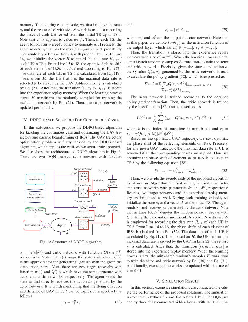
IV. DDPG-BASED SOLUTION FOR CONTINUOUS CASES
In this subsection, we propose the DDPG-based algorithm
for tackling the continuous case and optimizing the UAV tra-
jectory and passive beamforming of IRSs. The UAV trajectory
optimization problem is firstly tackled by the DDPG-based
algorithm, which applies the well-known actor-critic approach.
We also show the architecture of DDPG algorithm in Fig. 3.
There are two DQNs named actor network with function
Environment Agent
Actor network
Target network
{st, at, rt, st+1}
Experience
replay memory
Mini-batchLoss
function
st, at
st+1, rt
Critic network
Target network
Policy
gradient
st
at
Transition
s’
Q(s’,a’)
Q(s,a)
s, a
s’, a’
a’
updating
updating
updating
updating
Fig. 3: Structure of DDPG algorithm
a = π(s|δπ) and critic network with function Q(s, a|δQ)respectively. Note that π(·) maps the state and action, Q(·)is the approximator for generating Q-value with the given the
state-action pairs. Also, there are two target networks with
function π′(·) and Q′(·), which have the same structure with
actor and critic networks, respectively. The agent sends the
state st and directly receives the action at generated by the
actor network. It is worth mentioning that the flying direction
and distance of UAV in TS t can be expressed respectively as
follows
µt = xµt π, (28)
and
dt = |xdt |dmax, (29)
where xµt and xd
t are the output of actor network. Note that
in this paper, we denote tanh(·) as the activation function of
the output layer, which has xµt ∈ [−1.1], xd
t ∈ [−1, 1].Then, the transition is stored into the experience replay
memory with size of mmax. When the learning process starts,
a mini-batch randomly samples K transitions to train the actor
and critic networks. Precisely, given the state s and action a,
the Q-value Q(s, a), generated by the critic network, is used
to calculate the policy gradient [32], which is expressed as
∇δπJ =E[
∇aQ(s, a|δQ)|s=st,a=π(st|δπ)
· ∇δππ(s|δπ)|s=st
]
.(30)
The actor network is trained according to the obtained
policy gradient function. Then, the critic network is trained
by the loss function [32] that is described as
L(δQ) =1
K
K∑
k=1
(
yk −Q(sk, π(sk|δπ)|δQ)2
)
, (31)
where k is the index of transitions in mini-batch, and yk =rk + γQ(s′k, π
′(s′k|δπ′
)|δQ′
).Based on the optimized UAV trajectory, we next optimize
the phase shift of the reflecting elements of IRSs. Precisely,
for any given UAV trajectory, the maximal data rate at UE is
achieved if all the corresponding phases are aligned. Thus, we
optimize the phase shift of element m of IRS k to UE n in
TS t by the following equation [28]:
θk,n,m,t = ωUIk,m,t + ωIE
n,k,m. (32)
Then, we provide the pseudo code of the proposed algorithm
as shown in Algorithm 2. First of all, we initialize actor
and critic networks with parameters δπ and δQ, respectively.
Besides, two target networks and the experience replay mem-
ory are initialized as well. During each training episode, we
initialize the state st and a vector F at the initial TS. The agent
sends st and receives at generated by the actor network. Note
that in Line 10, N ′ denotes the random noise, η decays with
t, making the exploration successful. A vector R with size N
is employed for recording the data rate Rn,t of each UE in
TS t. From Line 14 to 16, the phase shifts of each element of
IRSs is obtained from Eq. (32). The data rate of each UE is
calculated by Eq. (19). Then, based on R, the UE that has the
maximal data rate is served by the UAV. In Line 22, the reward
rt is calculated. After that, the transition [st, at, rt, st+1] is
stored into the experience replay memory. When the learning
process starts, the mini-batch randomly samples K transitions
to train the actor and critic network by Eq. (30) and Eq. (31).
Additionally, two target networks are updated with the rate of
τ = 0.01.
V. SIMULATION RESULT
In this section, extensive simulations are conducted to evalu-
ate the performance of the proposed solutions. The simulation
is executed in Python 3.7 and Tensorflow 1.15.0. For DQN, we
deploy three fully-connected hidden layers with [400, 300, 64]
8
Algorithm 2 DDPG based algorithm
1: Initialize actor π(·) and critic Q(·) network with parame-
ters δπ and δQ respectively;
2: Initialize target networks π′(·), Q′(·) with parameters
δπ′
= δπ , δQ′
= δQ;
3: Initialize experience replay memory with size mmax;
4: for Episode = 1,2,...,Neps do
5: t = 0;
6: Initialize state st = [XU0 , Y U
0 , emax];7: Initialize vector F with size N :
8: while et > 0 do
9: Obtain st;
10: Select at = π(st|δπ) + ηN ′;
11: Execute at;
12: Obtain et from Eq. (7);
13: Initialize vector R with size N ;
14: for UE n = 1, 2, ..., N do
15: Obtain the optimized phase shift of each element
of IRSs in TS t from Eq. (32);
16: Calculate the data rate Rn,t of UE n according to
Eq. (19);
17: R(n)← Rn,t;
18: end for
19: n = argmaxRn∈N
;
20: F (n)← F (n) + 1;
21: Calculate ft from F ;
22: Obtain rt according to Eq. (21);
23: Store transition [st, at, rt, st+1] into experience re-
play memory;
24: if experience replay memory is full then
25: Randomly sample K transitions from experience
replay memory;
26: Update critic network according to Eq. (31);
27: Update actor network according to Eq. (30);
28: Update two target networks with the rate of τ ;
29: end if
30: t = t+ 1;
31: end while
32: end for
neurons and the AdamOptimizer is used to update DQNs
with the rate of 0.00001. The number of flying directions
of the UAV is set as Nµ = 6 and the number of flying
distance values of UAV is set as Nd = 3. Also, the number
of phase shift values of each reflecting element is set as
N I = 12. For DDPG-based solution, we deploy four fully-
connected hidden layers with [400, 300, 256, 128] neurons in
both actor and critic networks and AdamOptimizer is used
to train the actor network with the rate of 0.0001 and critic
network with the rate of 0.0002. The coordinates of IRSs are
set as [100, 0, 100], [300, 0, 100], [500, 0, 100], [100, 200, 100],[300, 200, 100], [500, 200, 100], and the coordinates of UEs
are set as [100, 50], [300, 50], [500, 50], [100, 150], [300, 150],[500, 150]. More parameters can be found in Table. II.
For comparison, we present two benchmark algorithms as
follows:
TABLE II: Main Notations.
Notation Description Notation Description
K 7 N 6
M 20 Xmax 600 m
Y max 200 m [XU0, Y U
0, HU ] [10, 10, 200]
T d 1 s T 50
dmax 40 m β 2.8
α -30 dB d λ2
Ur 120 m/s Vh 4.03
d0 0.6 ρa 1.225 kg/m3
z 0.05 A 0.503 m2
emax 20000 Ps 79.85
Pm 88.63 σ2 -70 dBm
P 0.01 W ki 100
kq 1 Nµ 6
Nd 3 NI 12
Neps 10000 ǫ 0.9
N ′ 1.3 γ 0.99
K 128 mmax 200000
η 0.9995 p 1
• Random: In this setting, the UAV randomly selects the
flying direction and distance in each TS. Also, it applies
the same optimization method of phase shifts as the
DQN-based solution.
• Greedy: In each TS, the UAV moves to the place for
maximizing the reward function in Eq. (21). Also, the
optimization of phase shifts is the same as the DQN-
based solution.
First, we depict the accumulated reward of the proposed
DQN-based and DDPG-based algorithm of the training pro-
cedure in Fig. 4, where the number of IRSs is set to 3, the
number of reflecting elements is 20, ki = 100, and kq = 1. As
shown in Fig. 4(a), the curve of accumulated reward remains
negative at the beginning. This is because the UAV may have
poor attempts, such as flying out of the target area, resulting
in negative reward, i.e, penalty. Additionally, one can see that
the accumulated reward increases rapidly at the later stage
and the networks start to converge. Eventually, the curve
of accumulated reward remain between 15 and 20, which
means that the agent has achieved the best options of UAV
trajectory and the phase shifts of the reflecting elements. Then,
in Fig. 4(b), DDPG also has the similar trend as DQN in
Fig. 4(a). Specifically, the curve of the accumulated reward
starts to increase from −25 at the beginning. This is because
the UAV may fly out of the target area and the penalty is
incurred. Then, the learning procedure starts and both actor
and critic networks learn to converge, leading to the increase of
the accumulated reward. Eventually, one can observe that the
curve of accumulated reward remains about 30, which means
the networks obtains the best options of trajectory of the UAV
and phase shifts of the reflecting elements of IRSs.
Then, we depict the accumulated reward of the proposed
DQN-based and DDPG-based algorithm of the training pro-
cedure in Fig. 5, where the number of IRSs is set to 6, the
number of reflecting elements is 20, ki = 100, and kq = 1. In
Fig. 5(a), we observe that the curve of DQN starts to increase
from −30 at the beginning, then it remains between 30 and
40. One can also see that from Fig. 5(b) that the accumulated
reward of DDPG finally remains above 40.
9
0 2000 4000 6000 8000 10000Training episodes
−140
−120
−100
−80
−60
−40
−20
0
20
Accumulative rewa
rd
DQN
(a)
0 2000 4000 6000 8000 10000���������� ������
−40
−30
−20
−10
0
10
20
30
����
��������
����
DDPG
(b)
Fig. 4: Accumulated reward of (a) DQN and (b) DDPG
versus training episodes (with 3 IRSs).
TABLE III: Performance Analysis.
Algorithm Number of IRSs Number of TSs Overall reward
DDPG3 77 33.366 75 49.58
DQN3 75 27.386 117 43.43
Greedy3 104 22.506 104 22.98
Random3 152 -85.616 157 -85.73
Once the training is done, we can evaluate the performance
of the proposed DDPG and DQN-based solutions. In Table III,
we show the number of TSs and the overall reward of DDPG,
DQN, Greedy and Random solutions that can achieve in one
episode. When the number of IRSs is 3, we observe that the
UAV controlled by DDPG can serve UEs for 77 TSs, achieving
the overall reward of 33.36. Also, DQN can serve UEs for 75TSs, and achieve the overall reward of 27.38. However, Greedy
can only achieve 22.50 of the overall reward, although it can
0 2000 4000 6000 8000 10000���������� ������
−30
−20
−10
0
10
20
30
40
����
��������
����
DQN
(a)
0 2000 4000 6000 8000 10000���������� ������
−40
−20
0
20
40
����
��������
����
DDPG
(b)
Fig. 5: Accumulated reward of (a) DQN and (b) DDPG
versus training episodes (with 6 IRSs).
serve UEs for more TSs. Note that our objective is to achieve
the the highest reward, and therefore the number of TSs served
is not our first priority. Similarly, when the number of IRSs is
6, we can also observe that DDPG outperforms DQN, Greedy
and Random in terms of the overall reward. DQN performs
worse than DDPG, as DQN can only have discrete/limited
options, but it is more suitable for some practical system
with hardware limit. Additionally, one can see that no matter
how many IRSs are employed, the overall reward of Random
always remains negative. This is because the UAV controlled
by Random may always fly out of the target area and achieve
the penalty.
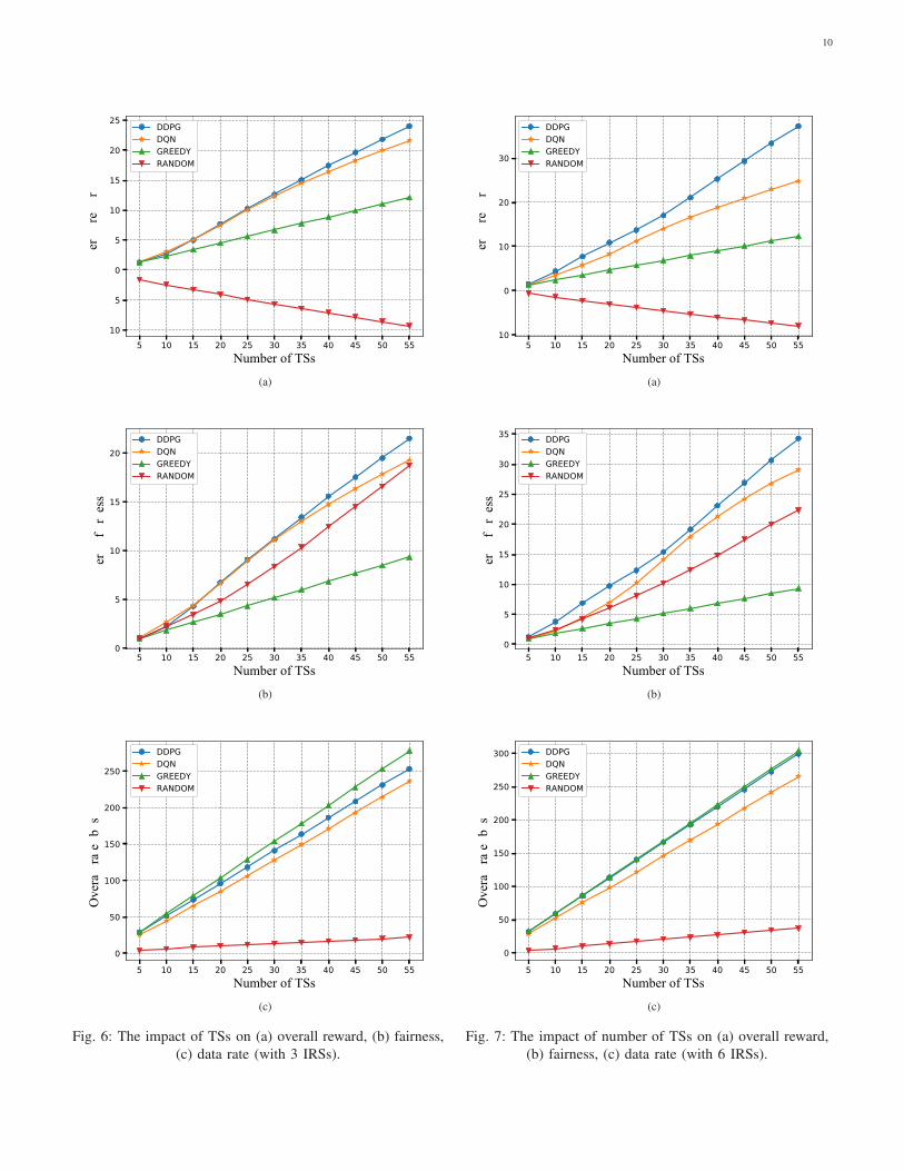
Then, we evaluate the performance in terms of overall
reward, fairness, data rate of UEs in different number of TSs
in Fig. 6, where the number of IRSs is set to 3. From Fig. 6(a),
we analyse the impact of the number of TSs on the overall
reward. One observes that as the number of TSs increases, the
overall reward of DDPG, DQN and Greedy both increases.
Specifically, the DDPG outperforms the solutions of DQN,
10
5 10 15 20 25 30 35 40 45 50 55����� ������
−10
−5
0
5
10
15
20
25
��� �� ��� �
DDPGDQNGREEDYRANDOM
(a)
5 10 15 20 25 30 35 40 45 50 55������� �����
0
5
10
15
20
����������
���
DDPGDQNGREEDYRANDOM
(b)
5 10 15 20 25 30 35 40 45 50 55������������
0
50
100
150
200
250
���
� ������
����
��
DDPGDQNGREEDYRANDOM
(c)
Fig. 6: The impact of TSs on (a) overall reward, (b) fairness,
(c) data rate (with 3 IRSs).
5 10 15 20 25 30 35 40 45 50 55����� ������
−10
0
10
20
30
��� �� ��� �
DDPGDQNGREEDYRANDOM
(a)
5 10 15 20 25 30 35 40 45 50 55������� �����
0
5
10
15
20
25
30
35
����������
���
DDPGDQNGREEDYRANDOM
(b)
5 10 15 20 25 30 35 40 45 50 55������������
0
50
100
150
200
250
300
���
� ������
����
��
DDPGDQNGREEDYRANDOM
(c)
Fig. 7: The impact of number of TSs on (a) overall reward,
(b) fairness, (c) data rate (with 6 IRSs).
11
Greedy and Random, as reasons explained before. Moreover,
one can see that Random performs the worst and it decreases
with the number of TSs, as no proper control algorithm is
applied. In Fig. 6(b), we analyse the overall fairness that
DDPG, DQN, Greedy and Random can achieve in different
number of TSs. Specifically, one sees that DDPG can achieve
better performance than DQN whereas Greedy performs worse
than Random. We further analyse the impact of number of TSs
on data rate in Fig. 6(c). One observes that Random performs
the worst compared to the other benchmark algorithms, as
DDPG and DQN perform slightly worse than Greedy. This
is because Greedy always controls the UAV fly to the place
where it achieves the best data rate, at the cost of fairness.
From Fig. 6(b) and Fig. 6(c), one can see that it is quite
challenging to achieve the optimal performance of fairness and
data rate at the same time. This is because on one hand, the
UAV will keep moving to serve different UEs for maximizing
the fairness, which will inevitably reduce the data rate and
consume more energy of UAV. On the other hand, the UAV
will tend to stay at the location that can achieve the maximal
data rate, which will have a negative effect on maximizing the
fairness.
Furthermore, we depict the performance of overall reward,
fairness and data rate of DDPG, DQN, Greedy and Random in
different number of TSs in Fig. 7, where the number of IRSs
is set to 6. We first compare the overall reward achieved by
DDPG, DQN, Greedy and Random in Fig. 7(a). One can see
that DDPG achieve the best performance. This is because the
proposed DDPG algorithm always tries to find the best UAV
trajectory and phase shifts for maximizing the overall reward
function. Similarly, DQN has the good performance, which is
very suitable for the practical system with hardware limit. The
Greedy solution increases with the number of TSs as well and
it performs better than Random, as the UAV controlled by
Random may fly out of the target area and achieve reward
deduction.
Then, as shown in Fig. 7(b), we observe that the fairness of
DDPG increases rapidly with the increase of the number of
TSs, and it consistently outperforms DQN, Greedy and Ran-
dom, as expected. Similarly, DQN achieves better performance
with the increases of the number of TSs and it eventually
remains about 30.
Next, we analyse the performance of DDPG, DQN, Greedy
and Random in terms of data rate in different number of TSs in
Fig. 7(c). Specifically, Greedy achieves the best performance
in terms of data rate, whereas DDPG performs slightly worse
than Greedy, as the reason explained before. As expected,
one observes that DQN performs worse than DDPG and
outperforms Greedy and Random.
Overall, from Fig.7 and Fig. 6, one can conclude that the
proposed DDPG and DQN achieve the best balance between
fairness and data rate, whereas Random and Greedy cannot
balance them.
VI. CONCLUSION
In this paper, we studied the joint optimization of trajectory
of UAV and passive phase shift of reflection elements in an
IRS-assisted UAV communication system, while maximizing
the geographical fairness and data rate of all the UEs served
by the UAV. We first proposed a DQN-based solution by
discretizing the trajectory and phase shift, which has low com-
plexity and is suitable for systems with hardware limits. Then,
to tackle the continuous scenario, we have further proposed
a DDPG-based solution, which applies to the system where
the phase shifts of IRS can be adjusted continuously. The
experimental results prove that the proposed solutions achieve
better performance compared to other traditional benchmarks.
REFERENCES
[1] Y. Zeng, R. Zhang, and T. J. Lim, “Wireless communications withunmanned aerial vehicles: opportunities and challenges,” IEEE Com-
munications Magazine, vol. 54, no. 5, pp. 36–42, 2016.
[2] A. Al-Hourani, S. Kandeepan, and S. Lardner, “Optimal LAP altitudefor maximum coverage,” IEEE Wireless Communications Letters, vol. 3,no. 6, pp. 569–572, 2014.
[3] Q. Wu and R. Zhang, “Common throughput maximization in UAV-enabled OFDMA systems with delay consideration,” IEEE Transactions
on Communications, vol. 66, no. 12, pp. 6614–6627, 2018.
[4] H. Ren, C. Pan, K. Wang, W. Xu, M. Elkashlan, and A. Nallanathan,“Joint transmit power and placement optimization for URLLC-enabledUAV relay systems,” IEEE Transactions on Vehicular Technology, pp.1–6, 2020.
[5] Y. Zeng, J. Xu, and R. Zhang, “Energy minimization for wirelesscommunication with rotary-wing UAV,” IEEE Transactions on WirelessCommunications, vol. 18, no. 4, pp. 2329–2345, 2019.
[6] Y. Zeng and R. Zhang, “Energy-efficient UAV communication with tra-jectory optimization,” IEEE Transactions on Wireless Communications,vol. 16, no. 6, pp. 3747–3760, 2017.
[7] C. H. Liu, Z. Chen, J. Tang, J. Xu, and C. Piao, “Energy-efficientUAV control for effective and fair communication coverage: A deepreinforcement learning approach,” IEEE Journal on Selected Areas in
Communications, vol. 36, no. 9, pp. 2059–2070, 2018.
[8] Z. Yang, C. Pan, K. Wang, and M. Shikh-Bahaei, “Energy efficientresource allocation in UAV-enabled mobile edge computing networks,”IEEE Transactions on Wireless Communications, vol. 18, no. 9, pp.4576–4589, 2019.
[9] W. Huang, Z. Yang, C. Pan, L. Pei, M. Chen, M. Shikh-Bahaei,M. Elkashlan, and A. Nallanathan, “Joint power, altitude, location andbandwidth optimization for UAV with underlaid D2D communications,”IEEE Wireless Communications Letters, vol. 8, no. 2, pp. 524–527, 2019.
[10] C. Zhan, Y. Zeng, and R. Zhang, “Energy-efficient data collection inUAV enabled wireless sensor network,” IEEE Wireless Communications
Letters, vol. 7, no. 3, pp. 328–331, 2018.
[11] C. H. Liu, Z. Chen, and Y. Zhan, “Energy-efficient distributed mobilecrowd sensing: A deep learning approach,” IEEE Journal on SelectedAreas in Communications, vol. 37, no. 6, pp. 1262–1276, 2019.
[12] J. Xu, Y. Zeng, and R. Zhang, “UAV-enabled wireless power transfer:Trajectory design and energy optimization,” IEEE Transactions on
Wireless Communications, vol. 17, no. 8, pp. 5092–5106, 2018.
[13] T. J. Cui, M. Q. Qi, X. Wan, J. Zhao, and Q. Cheng, “Codingmetamaterials, digital metamaterials and programmable metamaterials,”Light: Science & Applications, vol. 3, no. 10, p. e218, 2014.
[14] L. Li, T. J. Cui, W. Ji, S. Liu, J. Ding, X. Wan, Y. B. Li, M. Jiang,C.-W. Qiu, and S. Zhang, “Electromagnetic reprogrammable coding-metasurface holograms,” Nature communications, vol. 8, no. 1, pp. 1–7,2017.
[15] Q. Wu and R. Zhang, “Intelligent reflecting surface enhanced wirelessnetwork via joint active and passive beamforming,” IEEE Transactions
on Wireless Communications, vol. 18, no. 11, pp. 5394–5409, 2019.
[16] K. Wang, Y. Chen, and M. Di Renzo, “Outage probability of dual-hop selective af with randomly distributed and fixed interferers,” IEEE
Transactions on Vehicular Technology, vol. 64, no. 10, pp. 4603–4616,2015.
[17] Q. Wu and R. Zhang, “Intelligent reflecting surface enhanced wirelessnetwork: Joint active and passive beamforming design,” in 2018 IEEEGlobal Communications Conference (GLOBECOM), 2018, pp. 1–6.
[18] Y. Yang, B. Zheng, S. Zhang, and R. Zhang, “Intelligent reflectingsurface meets OFDM: Protocol design and rate maximization,” IEEE
Transactions on Communications, 2020.
12
[19] C. Huang, A. Zappone, G. C. Alexandropoulos, M. Debbah, andC. Yuen, “Reconfigurable intelligent surfaces for energy efficiency inwireless communication,” IEEE Transactions on Wireless Communica-
tions, vol. 18, no. 8, pp. 4157–4170, 2019.[20] X. Yu, D. Xu, and R. Schober, “Enabling secure wireless
communications via intelligent reflecting surfaces,” arXiv preprintarXiv:1904.09573, 2019.
[21] G. Zhou, C. Pan, H. Ren, K. Wang, and A. Nallanathan, “Intelligentreflecting surface aided multigroup multicast MISO communicationsystems,” IEEE Transactions on Signal Processing, 2020.
[22] C. Pan, H. Ren, K. Wang, W. Xu, M. Elkashlan, L. Hanzo, andA. Nallanathan, “Multicell MIMO communications relying on intelligentreflecting surfaces,” IEEE Transactions on Wireless Communications,2020.
[23] C. Pan, H. Ren, K. Wang, M. Elkashlan, A. Nallanathan, J. Wang, andL. Hanzo, “Intelligent reflecting surface enhanced MIMO broadcast-ing for simultaneous wireless information and power transfer,” arXivpreprint arXiv:1908.04863, 2019.
[24] T. Bai, C. Pan, Y. Deng, M. Elkashlan, A. Nallanathan, and L. Hanzo,“Latency minimization for intelligent reflecting surface aided mobileedge computing,” IEEE Journal on Selected Areas in Communications,pp. 1–17, 2020.
[25] A. Zappone, M. Di Renzo, F. Shams, X. Qian, and M. Debbah,“Overhead-aware design of reconfigurable intelligent surfaces in smartradio environments,” arXiv preprint arXiv:2003.02538, 2020.
[26] X. Yu, D. Xu, and R. Schober, “Optimal beamforming for MISOcommunications via intelligent reflecting surfaces,” arXiv preprintarXiv:2001.11429, 2020.
[27] C. Huang, R. Mo, C. Yuen et al., “Reconfigurable intelligent surface as-sisted multiuser MISO systems exploiting deep reinforcement learning,”arXiv preprint arXiv:2002.10072, 2020.
[28] S. Li, B. Duo, X. Yuan, Y.-C. Liang, and M. Di Renzo, “Reconfigurableintelligent surface assisted UAV communication: Joint trajectory designand passive beamforming,” IEEE Wireless Communications Letters,vol. 9, no. 5, pp. 716–720, 2020.
[29] D. Ma, M. Ding, and M. Hassan, “Enhancing cellular communi-cations for UAVs via intelligent reflective surface,” arXiv preprint
arXiv:1911.07631, 2019.[30] R. S. Sutton and A. G. Barto, Reinforcement Learning: An Introduction.
Cambridge, MA, USA: A Bradford Book, 2018.[31] V. Mnih, K. Kavukcuoglu, D. Silver, A. A. Rusu, J. Veness, M. G.
Bellemare, A. Graves, M. Riedmiller, A. K. Fidjeland, G. Ostrovskiet al., “Human-level control through deep reinforcement learning,”Nature, vol. 518, no. 7540, pp. 529–533, 2015.
[32] T. P. Lillicrap, J. J. Hunt, A. Pritzel, N. Heess, T. Erez, Y. Tassa,D. Silver, and D. Wierstra, “Continuous control with deep reinforcementlearning,” arXiv preprint arXiv:1509.02971, 2015.
[33] A. G. Barto, R. S. Sutton, and C. W. Anderson, “Neuronlike adaptiveelements that can solve difficult learning control problems,” IEEETransactions on Systems, Man, and Cybernetics, vol. SMC-13, no. 5,pp. 834–846, 1983.
[34] D. Tse and P. Viswanath, Fundamentals of wireless communication.Cambridge university press, 2005.
[35] R. K. Jain, D.-M. W. Chiu, and W. R. Hawe, “A quantitative measureof fairness and discrimination,” Eastern Research Laboratory, Digital