24
Jøtul F 500 USA USA/CAN - Installation and Operating Instructions 3 Kindly save these instructions for future reference. Jøtul F 500 USA Manual Version P15
Jøtul F 500 USA
USA/CAN - Installation and Operating Instructions 3
Kindly save these instructions for future reference.
Jøtul F 50
0 USA
Manual Version P15

2

3
Standards:
The Jøtul F 500 woodstove has been tested and listed to;U.S. Standards: ANSI/UL 737 and ANSI/UL 1482.Canadian Standards: CAN/ULC-S627-M93
Tests performed by: ITS Intertek Testing Services, Middleton, WI
Manufactured by: Jøtul A.S, P.O. Box 1411, N-1602 Fredrikstad, Norway
Distributed by: Jøtul North America Inc., 55 Hutcherson Drive, Gorham, Maine 04038, USA
This heater meets the U.S. Environment Protection Agency’s Emissions limits for wood heaters manufactured and sold after July 1, 1990.
Under specific test conditions, this heater has shown heat output at rates ranging from 12.000 to 34,700 BTU’s per hour.
The Jøtul F 500 woodstove is only listed to burn wood. Do not burn any other fuels.
When installing, operating and maintaining your Jøtul F 500 woodstove, follow the guidelines presented in these instructions, and make them available to anyone using or servicing the stove.
Installation and Operating Instructions for the USAInstallation et fonctionnement pour CanadaSafety notice: If this solid fuel room heater is not properly installed, a house fire may result. For your safety, follow the installation directions. Contact local building or fire officials about restrictions and installation inspection requirements in your area. Kindly save these instructions for future reference.
Avis de sécurité: Une installation non appropriée de ce poêle de chauffage risque de provoquer un incendie. Assurez votre sécurité en respectant les directives d’installation suivantes. Consultez les autorités locales du bâtiment ou de la prévention des incendies au sujet des restrictions et exigences relatives aux inspections d’installations dans votre région.
Tested and listed by ITS, Intertek Testing Services, Middleton, Wisconsin.Tested to U.S. Standards: ANSI/UL 1482 & 737, Canadian Standards: CAN/ULC-S627-M93
A number of areas require a building permit to install a solid fuel burning appliance.
In the U.S., the National Fire Protection Association’s Code, NFPA 211, Standards for Chimneys, Fireplaces, Vents and Solid Fuel Burning Appliances, or similar regulations, may apply to the installation of a solid fuel burning appliance in your area.
In Canada, the guideline is established by the CSA Standard, CAN/CSA-B365-M93, Installation Code for Solid-Fuel-Burning Appliances and Equipment.
Always consult your local building inspector or authority having jurisdiction to determine what regulations apply in your area.
Jøtul North America Inc.55 Hutcherson DriveGorham, Maine 04038USA
USA/CANADA
Accepted For UseCity of New York
Department of BuildingsMEA 313-00-E
Jøtul North America, Inc.
4
Safety notices:• Be sure to read this entire manual before you install or use
your new Jøtul F 500 woodstove.
• If this room heater is not properly installed, a house fire may result. To reduce the risk of fire, follow the installation instructions. Failure to follow these instructions may result in property damage, bodily injury, or even death.
• Jøtul recommends that you have your new Jøtul F 500 installed by a professional installer of solid fuel burning appliances.
• Extremely hot while in operation! Keep children, clothing and furniture away. Contact may cause skin burns.
• Avoid creating a low pressure condition in the room where the stove is operating. Operating an exhaust fan or a clothes dryer could create a low pressure area, causing poisonous gases to come out of the stove into the room.
• You can prevent low pressure conditions by providing adequate combustion air within 24” (610mm) but not closer than 12” (305mm) from the stove. Or, simply install the optional outside air manifold system, which allows the direct connection of air from outside the house to the stove.
• Do not use chemicals or fluids to start the fire. Some fuels will, during combustion, separate carbon monoxide and generate it in the burn chamber. Carbon monoxide is toxic, so please follow the guidelines in this manual for proper operation of your Jøtul F 500.
• If you for some reason experience smoke “roll-out” from the stove, it may activate smoke detectors if installed in the house.
Table of contents:Safety Notices .......................................................................................4
1.0 Installation1.1 Assembly before Installation .................................................... 5
2.0 Chimney and Chimney Connector2.1. Chimneys ....................................................................................... 5 2.2 Masonry Chimney ....................................................................... 6 2.3 Prefabricated Chimneys ............................................................. 6 2.4 Chimney Height ........................................................................... 6 2.5 Wall pass-throughs ..................................................................... 6
3.0 Connecting to the Chimney3.1 Masonry Chimney Thimbles ..................................................... 7 3.2 Hearthmount Into a Masonry Fireplace ................................ 7 3.3 Prefabricated Chimneys ............................................................. 7
4.0 Clearances to Combustibles4.1 Floor Protection ............................................................................ 8 4.2 Clearances to Walls and Ceilings ............................................. 8 4.3 Alcove Installations ..................................................................... 8 4.4 Mobile Home Installations ........................................................ 9
5.0 Operation5.1 Controls on The Jøtul F 500 ....................................................... 95.2 Breaking in Your New Stove ...................................................... 95.3 Starting and Maintaining a Fire ............................................... 105.4 Adding Fuel ................................................................................... 105.5 The Formation of Creosote ....................................................... 10
6.0 Maintenance6.1 Ash Removal.................................................................................. 11 6.2 Glass Care ...................................................................................... 11 .6.3 Chimney System .......................................................................... 11
7.0 General Maintenance7.1 Gaskets ........................................................................................... 12
8.0 Accessories8.1 Firescreen ....................................................................................... 12 8.2 Outside Air Kit .............................................................................. 128.3 Floor Bracket Kit ........................................................................... 138.4 Rear Heatshield ............................................................................ 138.5 Bottom Heatshield ...................................................................... 138.6 Stove-top Thermometer ............................................................ 13
9.0 Jøtul N. A. wood-burning product limited warranty .........21
Figures -Drawings ......................................................................... 14-16
Clearances ....................................................................................... 17-18
Exploded view ..................................................................................... 19
Appendix A (alternate floor protection)......... .............................. 20
USA/CANADA

5
1.0 InstallationIf this solid fuel room heater is not properly installed a house fire may result. For your safety, follow the installation directions. Contact the local building or fire officials about restrictions and installation inspection requirements in your area.
Reminder:Your local officials have final authority in determining if a proposed installation is acceptable. Any requirement, that is requested by the local authority having jurisdiction, that is not specifically addressed in this manual, defaults to NFPA 211, and local codes in the U.S. or in Canada, CAN/CSA-B365-M and local codes.
1.1 Assembly before InstallationThe Jøtul F 500 is shipped with the flue collar, gasketing and hardware inside the stove. • To install the flue collar in the top or rear exit position remove
the tape from the gasketing and adhere to the groove on the back of the stove around the flue opening.
• Place the flue collar on the stove in the top or rear exit position and secure with the nut, bolt and washer.
• The nut and washer are placed on the inside of the stove.• Take out the ash lips, which are inside the burn chamber, and
install. The one in front is placed loosely on top of the base plate, while the side ash lip is fastened with the screw that is attached to the base plate.
2.0 Chimney and Chimney ConnectorThe chimney connector is a single walled pipe used to connect the stove to the chimney. For use with the Jøtul F 500, the chimney connector must be 6” (152mm) in diameter, with a minimum thickness of 24 gauge black steel.• Aluminum and Galvanized steel pipe is not acceptable for use
with the Jøtul F 500. These materials cannot withstand the extreme temperatures of a wood fire and can give off toxic fumes when heated.
• Do not use the connector pipe as a chimney.• Each chimney connector or stove pipe section must be
installed to the stove flue collar and to each other with the male (crimped) end toward the stove. See figure 2.
• This prevents any amount of condensed or liquid creosote from running down the outside of the pipe or the stove top.
• All joints, including the flue collar connection must be secured with three sheet metal screws.
• For the best performance the chimney connector should be as short and direct as possible, with no more than two 90° elbows.
• The maximum horizontal run is 36” (915mm) and a recommended total length of stove pipe should not exceed 10 feet.
• Always slope horizontal runs upward 1/4” (6,35mm) per foot toward the chimney.
• No part of the chimney connector may pass through an attic or roof space, closet or other concealed space, or through a floor or ceiling.
• All sections of the chimney connectors must be accessible for cleaning.
• Where passage through a wall or partition of combustible construction is desired, the installation must conform with NFPA 211 or CAN/CSA-B365, and is also addressed in this manual.
• Do not connect this unit to a chimney flue servicing another appliance.
2.1 ChimneysThere are two types of chimneys suitable for the Jøtul F 500: 1. A code- approved masonry chimney with a flue liner.2. A prefabricated chimney complying with the requirements
for Type HT (2100°F) chimneys per UL 103 or ULC S629.
The chimney size should not be less than the cross-sectional area of the flue collar, and not more than three times greater than the cross-sectional area of the flue collar.
When selecting a chimney type and the location for the chimney in the house, keep this in mind: it is the chimney that makes the stove work, not the stove that makes the chimney work. This is because a chimney actually creates a suction, called “draft”, which pulls air through the stove.
Several factors affect draft: chimney height, cross-sectional area (size), and temperature of the chimney, as well as the proximity of surrounding trees or buildings.
As a result, a short masonry chimney on the exterior of a house will give the poorest performance. This is because it can be very difficult to warm the chimney thereby creating inadequate draft. In extremely cold northern areas it may be necessary to reline the chimney or extend its height to help establish draft.Conversely, a tall masonry chimney inside the house is easier to keep warm and will perform the best.
USA/CANADA
6
The following guidelines give the necessary chimney requirements based on the national code (ANSI-NFPA 211for the US. And CSA CAN-B365 for Canada). However, many local codes differ from the national code to take into account climate, altitude, or other factors.
Notice:It is important that you check with your local building officials to find out what codes apply in your area before installing your new Jøtul F 500.Remember: Your local inspector(s) have the final authority in approving your installation. It is always best to consult with them prior to the installation.
2.2 Masonry ChimneysWhen installing the Jøtul F 500 into a masonry chimney you must conform to all of the following guidelines:
• The chimney flue size should not be less than the cross-sectional area of the stove flue collar.
• The cross-sectional area of the flue of a chimney with no walls exposed to the outside below the roofline shall not be more than three times the cross-sectional area of the stove flue collar.
• The cross-sectional area of the flue of a chimney with one or more walls exposed to the outside below the roofline shall not be more than two times the cross-sectional area of the stove flue collar.
• Larger chimney flues should be relined with a listed or code approved liner.
• The masonry chimney must have a fireclay liner or equivalent, with a minimum thickness of 5/8” (16mm) and must be installed with refractory mortar. There must be at least 1/4” (6,35mm) air space between the flue liner and chimney wall.
• The fireclay flue liner must have a nominal size of 8” X 8”, and should not be larger than 8” X 12”. If a round fireclay liner is to be used it must have a minimum inside diameter of 6” (157mm) and not larger than 8” (208mm) in diameter.
• If a chimney with larger dimensions is to be used, it should be relined with an appropriate liner that is code approved.
• The masonry wall of the chimney, if brick or modular block, must be a minimum of 4”(106mm) nominal thickness. A mountain or rubble stone wall must be at least 12” (310mm) thick.
• A newly-built chimney must conform to local codes and in their absence must recognize national regulations. W h e n using an existing chimney, it must be inspected by a licensed professional chimney sweep, fire official, or code officer, to ensure that the chimney is in proper working order.
• No other appliance can be vented into the same flue.• An airtight clean-out door should be located at the base of
the chimney.
2.3 Prefabricated ChimneysIf a prefabricated metal chimney is to be used it must be a chimney type that is tested and listed for use with solid fuel burning appliances. That means a chimney that is tested to the following:
High Temperature (HT) Chimney Standard UL 103 for the U.S. and High Temperature Standard ULC S-629 for Canada.
The manufacturer’s installation instructions must be followed precisely. Always maintain the proper clearance to combustibles as established by the pipe manufacturer. This clearance is usually a minimum of 2” (56mm), although it may vary by manufacturer or for certain chimney components.
2.4 Chimney HeightWhether a masonry chimney or prefabricated metal chimney is used it must be the required height above the roof line. The requirement is:The chimney must be at least 3 feet higher than the highest point where it passes through the roof and at least 2 feet higher than the highest part of the roof or structure that is within 10 feet of the chimney, measured horizontally. See figure 3.
Chimneys shorter than 14 feet may not provide adequate draft. This could result in smoke spilling into the room from the stove when loading the stove, or when the door is open. In addition, inadequate draft can cause back puffing, which is a build up of gases inside the firebox. Other times, chimney height can create excessive draft which can cause high stove temperatures and short burn times. Excessive drafts can be corrected by installing a butterfly damper. If you suspect you have a draft problem, consult your dealer.
2.5 Wall Pass-throughsWhen your installation unavoidably requires the chimney connector to pass through a combustible wall to reach the chimney, always consult your local building officials, and be sure any materials to be used have been tested and listed for wall pass-throughs.
In the U.S.The National Fire Protection Association’s publication, NFPA 211, Standard for Chimneys, Fireplaces, Vents and Solid Fuel Burning Appliances permits four methods for passing through a combustible wall. Before proceeding with any method be sure to consult with your local building officials to discuss any local code requirements.
Common Method: • When passing through a combustible wall to a masonry
chimney this method requires the removal of all combustible materials from at least 12” (310mm) around the chimney connectors proposed location. With a 6” (157mm)round liner the minimum area required would be 31” x 31” (792x792mm) square.
• The space is then filled with at least 12” (310mm)of brick around a fireclay liner. Remember, the liner must be ASTM C35 or equivalent, with a minimum wall thickness of 5/8” (16mm).
• It is important to remember to locate the pass-through at least 18”(457mm) from the ceiling for proper clearance to combustibles.
• It will be necessary to cut wall studs, install headers, and construct a sill frame to maintain the proper dimensions and to support the weight of the brick.
• The bricks must be solid brick with a minimum of • 3 1/4 “ (83mm) thick (4” (106mm) nominal).• Refractory mortar must be used at the junction of the chimney
and the pass-through liner. The pass-through liner must not penetrate the chimney liner beyond the inner surface of the chimney liner. Use extreme care when constructing the hole in the chimney liner, the tiles can shatter easily. See figure 4.
USA/CANADA

7
In Canada In Canada the standard has been established by the Canadian Standard Association. The installation must conform to CAN/CSA-B365, Installation Code for Solid Fuel Burning Appliances and Equipment. Before proceeding be sure to consult your local building inspector.
Common Method:This method requires the removal of all combustible materials from at least 18” (457mm) around the chimney connector’s proposed location. With a 6” (157mm) round liner the minimum area required would be 43” x 43” square (1092x1092mm).
It is important to remember to locate the pass-through at least 18” (457mm) from the ceiling to maintain the proper clearance to combustibles.
The space that is cleared of combustible materials must then remain empty. Sheet metal panels can then be used to cover the area. However, when using a panel on both sides of the wall each cover must be installed on noncombustible spacers at least 1”(25,4mm) from the wall. If one panel of sheet metal is to be used it may be installed flush to the wall.
See section 5.3.1 and 5.3.2 of CAN/CSA - B365-M91.Consult your local building inspector, authorized Jøtul Dealer, NFPA 211 in the U.S. or CAN/CSA-B635 in Canada for other approved wall pass-through methods.
3.0 Connecting to the chimney3.1 Masonry Chimney ThimblesWhen installing a Jøtul F 500 into a masonry chimney through a “thimble”(the opening through the chimney wall to the flue), the thimble must be lined with ceramic tile or metal and be securely cemented in place.
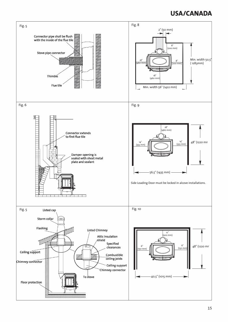
The chimney connector/stove pipe must slide completely inside the thimble to the inner surface or the flue liner. It may be necessary to make use of a thimble sleeve (a pipe with a slightly smaller diameter than standard stove pipe). This special pipe can be easily installed into a thimble. See figure 5.
Make sure the connector pipe or thimble sleeve does not protrude into the flue liner, thereby restricting the area the smoke has to flow through. This bottle-neck will have a negative affect on the chimney system. The chimney connector should be sealed at the thimble with refractory cement and the stove pipe leading to the stove should have a minimum of three screws. Do not connect this stove to a chimney flue servicing another appliance of any kind.
3.2 Hearthmount Into a Masonry FireplaceThe Jøtul F 500 has a rear exit flue collar height of 28 1/4” (718 mm) when installed with standard legs. Substitution of Short Legs will lower the height to 26” (660 mm).
When installing the Jøtul F 500 into a masonry fireplace, code requires that the fireplace damper plate be removed or securely fixed in the open position. A connector pipe must then extend from the stove’s flue exit through the damper area of the fireplace and into the chimney tile liner. See figure 6.The inside area of the flue liner must not be less than the area of the stove’s flue exit, and cannot be more than three times greater than the cross sectional area of the stove’s flue exit.If the chimney liner is too large to accommodate the stove, an approved relining system must be installed to resize the flue. A new sheet metal damper block-off plate must be installed around the connector pipe at the damper frame and sealed with the proper sealant (usually High-Temp Silicone).
Fireplace installation must also observe the proper clearances to surrounding trim and mantels (addressed in clearance section of this manual). In addition, fireplace installations must also adhere to the floor protection guidelines specified in the following section.
3.3 Prefabricated ChimneysWhen installing the Jøtul F 500 to a prefabricated metal chimney always follow the pipe manufacture’s instructions and be sure to use the components that are required. This usually includes some type of “smoke pipe adapter” that is secured to the bottom section of the metal chimney and allows the chimney pipe to be secured to it with three sheet metal screws. See figure 7.
USA/CANADA
8
4.0 Clearances to Combustibles4.1 Floor ProtectionFloor protection under the stove must be a UL 1618 Type I Ember Protector composed of non-combustible material for protection from radiant heat, sparks, and embers.
Individual sections of floor protection must be mortared together to prevent sparks from falling through to combustible materials. Any carpeting must be removed from under the floor protection.
In the U.S. and CanadaThe Jøtul F 500 must be installed on a non-combustible surface extending:
A minimum of 18” (457mm) in front of the stove and the left side load door (measured from the legs).And 8” (200mm) on the right side and back of the stove (measured from side and back panels).
This will result in a minimum floor protection of 54,25”W X 50,5”D.(1378mm x 1283mm) See figure 8.
In a rear vent installation the floor protection must also extend under the stove pipe a minimum of 2” (50mm) beyond either side of the pipe.
Alternate hearth protectionA h e a r t h p a d m e a s u r i n g 4 6 ” w i d e X 5 0, 5 ” d e e p (1168mmx1283mm)can be used only if the left side door is locked to prevent use. Door Lock Kit #155850 is available for this purpose.
4.2 Clearances to Walls and CeilingsThe following clearances have been tested to UL and ULC standards and are the minimum clearances specifically established for the Jøtul F 500.
The following diagrams give the required clearances you must maintain when installing the Jøtul F 500 near combustible surfaces. See pages 17-18.
A combustible surface is anything that can burn (i.e. sheet rock, wall paper, wood, fabrics etc.). These surfaces are not limited to those that are visible and also include materials that are behind non-combustible materials. If you are not sure of the combustible nature of a material, consult your local fire officials. Contact your local building officials about restrictions and installation requirements in your area.Remember: “Fire Resistant” materials are considered combustible; they are difficult to ignite, but will burn. Also “Fire-rated” sheet rock is also considered combustible.
Using Shields to Reduce ClearancesPipe shields: When using listed pipe shields to reduce the connector clearance to combustibles, it must start 1”(25,4mm) above the lowest exposed point of the connect pipe and extend vertically a minimum of 25” (635mm) above the top surface of the stove.
Double wall pipe: Listed double wall pipe is an acceptable alternative to connector pipe heatshields.
Wall-Mounted Protection: When reducing clearances through the use of wall mounted protection:
In the U.S. refer to NFPA 211, Standard for Chimneys, Fireplaces, Vents and Solid Fuel Burning Appliances, for acceptable materials, proper sizing and construction guidelines. In Canada, refer to CAN/CSA-B365, Installation Code for Solid-Fuel Burning Appliances and Equipment, also for acceptable materials, proper sizing and construction guidelines.
Stove Mounted Heatshield: A stove rear heatshield has been specifically designed for the Jøtul F 500. Rear heatshield part # 154332.
No other heat shield may be used. See pages 17-18 for complete clearance requirements and diagrams.
NoticeAccessories for wood stoves for clearance reduction have been developed by many manufacturers. If not following the methods of the installation codes, be sure that any accessory you choose has been tested by an independent laboratory and carries the laboratory’s testing mark. Make sure to follow all of the manufacturer’s instructions.
Always contact your local building inspector or fire officials about restriction and requirements in your area. Reminder, it is the local officials who have final authority for the installation approval.
4.3 Alcove InstallationThe Jøtul F 500 can be installed in an alcove situation provided: See figures 9 and 10.
1. The stove must be installed with listed double walled pipe.2. In a protected alcove installation both side walls and rear wall
must be protected per NFPA 211 or CAN/CSA-B365. The wall protection must be elevated 1”(24,5mm) from the floor and at least 1” (24,5mm)off the combustible wall to allow for an air-flow.
3. The height of the wall protection including the bottom air space must be 48”(1219mm).
4. The bottom heatshield is required in all alcove installations.5. H e a r t h p r o t e c t i o n m a t e r i a l m u s t c o n s i s t o f :
a) a UL/ULC listed Type II Thermal Floor Protector or, b) material having a minimum r value of 1.6 (see appendix a).
6. Minimum ceiling height in an unprotected installation, off the top of the stove is 41”(1041 mm). The minimum ceiling height off the top of the stove in a protected ceiling installation is 15”(380mm).
Use of the left side load door is prohibited in alcove installations.
USA/CANADA
9
4.4 Mobile Home InstallationsThe Jøtul F 500 has been approved for use in mobile homes in the U.S. and Canada, provided:
1. The stove is secured to the floor or the mobile home. Floor mounting kit #750304.
2. The stove is provided outside air for combustion. Outside Air kit #154333 (see page 11 for more details)
3. The stove must be grounded to the mobile home frame per NFPA 70.
As always, consult with your local building inspector or fire officials about restrictions and requirements in your area prior to installing the stove.
WARNING:Do not install in a bedroom/sleeping room. The structural integrity of the mobile home’s floor, wall, ceiling/roof must be maintained.
5.0 OperationBefore building a fire in your new Jøtul F 500, please read the following section carefully and completely.
This stove is designed to burn natural wood only. Wood that has been air-dried for a period of 6 to 14 months will provide the cleanest most efficient heat.
Do not burn:* Coal * Treated or painted wood* Garbage * Chemical Chimney cleaners* Cardboard * Colored paper* Solvents * Any synthetic fuel or logs The burning of any of these materials can result in the release of toxic fumes. Never use gasoline, gasoline-type lantern fuel, kerosene, charcoal lighter fluid, or similar liquids to start or “freshen-up” the fire. Always keep such liquids away from the heater at all times.
ImportantNever build or allow the fire to rest directly on the glass. The logs should always be spaced at least one inch from the glass to allow for proper air flow within the stove.
5.1 Controls on The Jøtul F 500
A single air control lever controls the burn time and heat output of the stove. This primary air control lever is located on the front of the stove directly above the ashlip. The primary air lever controls the amount of air that enters the stove for combustion.
When first starting or reviving the fire: The primary control lever should be at the far right position, which allows the maximum amount of air into the stove. The more air entering the stove, the hotter the fire, the shorter the burn time. Moving the lever to the left reduces the air-flow into the stove which prolongs the fire at a lower heat output. See figure 11.
5.2 Breaking in Your New StoveYour new Jøtul F 500 is constructed of cast iron and stove furnace cement. This type of construction requires the stove to be “broken-in” gradually so that heat expansion does not occur too quickly and cause damage.
Complete the following steps for the proper break-in procedure for the Jøtul F 500:
To monitor the stove’s temperature, Jøtul recommends the use of a magnetic stove-top thermometer, placed directly on the corner of the stove’s top plate.
1. Light a small fire, newspaper and kindling only, only allow the stove to reach a maximum surface temperature of 200°. Burn for approximately1 hour.
2. Allow stove to cool to room temperature.3. Light a second fire, allowing the stove to reach a maximum
temperature of 300° for 1 hour.4. Cool the stove to room temperature.5. Light a third fire and gradually allow the stove to reach a
surface temperature of 400°6. Cool stove to room temperature. This completes the “break-in”
procedure.
USA/CANADA

10
Never allow the stove to exceed a 400° surface temperature during any “break-in fire” with the exception of the last “break-in” fire.
Note: It is normal for a new painted stove to emit an odor and even smoke during its first several fires. This is caused by the seasoning of the high temperature paint and will diminish with each fire and will eventually disappear. Opening a window or door to provide additional ventilation will reduce the odor as this process takes its course.
5.3 Starting and Maintaining a FireBurn only solid wood directly on the bottom grate of the stove, do not elevate the fire in any way.• The ash pan door on the stove must always be securely closed
when the stove is in operation.• Burning the stove with the ash pan door open will overfire
the stove and cause interior damage.• With the primary air control lever in the full open position,
start with several sheets of crumbled newspaper placed directly on the grate. On top of the newspaper, place several pieces of small dry kindling (approx. 1”(24,5mm) in diameter) with two to three larger logs (approx. 3”(76mm) to 5”(127mm) in diameter) on top.
• Light the fire and close the door, slowly building the fire by adding larger and larger logs. Be sure to follow the break-in procedure before creating a fire that will damage the stove.
• Once the stove has reached a surface temperature range of between 400° and 600°, adjust the primary air control lever as necessary to generate the heat output and burn time desired.
• Jøtul recommends the use of a magnetic stove top thermometer to monitor the surface temperature of the stove. The optimum surface temperature range for the most efficient burn is between 400° to 600°. See figure 12, for the optimum locations of a stove-top thermometer.
5.4 Adding FuelWhen reloading the stove while it is still hot and a bed of hot embers still exist, follow this reloading procedure:• Always wear gloves when tending to the stove.• Push the air control lever to the full open position (far
right).• Wait a few seconds before opening the door.• Use a stove tool or poker to distribute the hot embers equally
around the firebox.• Load the fuel, usually with smaller logs first.• Close the door, be sure to latch the door tightly.• Wait 5 – 10 minutes before adjusting the primary air to the
desired heat output setting. (If you have at least a 2”(50mm) thick ember bed when reloading, it may be possible to close the door and immediately adjust the air control setting).
5.5 The Formation of CreosoteCreosote and Soot Formation and the Need for RemovalWhen wood is burned slowly, it produces tar and other organic vapors which combine with expelled moisture to form creosote. These creosote vapors condense in the relatively cool chimney flue of a slow burning fire. The creosote that accumulates in the flue is highly flammable and is the fuel of chimney fires. To prevent a chimney fire, the creosote needs to be removed by sweeping the chimney and flue connector. The frequency of sweeping will depend on how you operate your stove, but it is important to inspect the flue after every two weeks of use. An accumulation of 1/4” or more on the sides of the flue or connector is considered hazardous and should be removed.In the event that creosote in your chimney or flue connector ignites, the resulting fire is often accompanied by a roaring noise and a crackling sound as flakes of burned creosote break loose. lf you suspect you are having a chimney fire, immediately close the draft regulator and make sure the stove door is closed. Call the fire department and get everyone safely out of the house.
Trying to extinguish the fire in the stove will not help. In fact it can make the matter worse by allowing oxygen through the door, which then supports the fire in the chimney. When the roaring and crackling has stopped, you should resist the temptation to open the door and look at the fire. The fire may have suffocated, but could rekindle when you open the door. After a chimney fire, do not use your stove until the chimney and the flue connector has been cleaned and inspected to ensure that no damage has been sustained.
USA/CANADA

11
6.0 MaintenanceFor your protection always wear safety gloves when handling the ash pan.
6.1 Ash removalAsh removal will be required periodically depending on how frequently the stove is used. Conveniently, the Jøtul F 500 is equipped with an ash pan assembly for easy ash removal, without the need for opening the front doors.
The ash pan door is located under the front ashlip of the stove. To open the ash door, rotate the door knob counterclockwise to unlatch the door and clockwise to latch the door.
Remove the ash pan. When the stove is in operation always close the ash door before leaving to dispose of the ashes.
The ashes should be placed in a metal container equipped with a tight sealing lid. The container should be placed on a noncombustible floor or on the ground, well away from all combustible materials, pending final disposal. If the ashes are disposed of by burial in soil or otherwise locally dispersed, they should be retained in the closed container until all cinders have thoroughly cooled. Only use a vacuum for this job if the vacuum is specifically designed for ashes.
Warning. Do not, at any time, operate this stove with the ash pan door open. This condition will lead to overfiring and will damage the stove. This damage is not covered under warranty. Only empty the ash drawer before refueling, when the fire is low or out. The ash door should be open only long enough to empty the ash drawer and then securely closed. Inspect the gasket on the ash pan door regularly and replace as necessary.
6.2 Glass CareCleaning: On occasion it will be necessary to clean the carbon deposits and fly ash off of the glass. If the carbon and fly ash are allowed to remain on the glass for an extended period of time it could eventually cause the glass to become etched and cloudy. Any creosote, which might deposit on the glass, should burn off during the next hot fire.
The proper cleaning procedure is as follows:1. Glass needs to be completely cool.2. Only use a cleaner that is specifically designed for cleaning
ceramic stove glass. DO NOT USE AMMONIA-BASED CLEANING SOLUTIONS. USE OF ABRASIVES WILL DAMAGE THE GLASS SURFACE.
3. Rinse and dry glass completely before burning your stove.Never operate the stove with a cracked or broken glass panel.
Glass removal: Always operate the doors slowly and cautiously to avoid cracking or breaking the glass. Never use the door to push wood into the firebox. If the glass becomes cracked or broken follow this procedure for replacement:
1. Remove the door from the stove and place on a flat surface.
2. Carefully remove all of the glass clips from the inside of the door.
3. Gently remove all pieces of the glass panel and gasketing.4. Remove all remaining debris from the glass area using a wire
brush.5. Apply a small bead of gasket/stove cement and the new
gasket. Do not overlap the ends of the gasket rope.6. Center the new glass panel over the gasket and reinstall the
glass clips. See figure 13.
Important: It is extremely important to tighten the glass clips slowly and in a repeating pattern, like tightening the lugs on an automobile wheel.It may be necessary to retighten the glass clips after the stove has burned and the gasketing has been seated.
Important: Replace glass only with a ceramic glass panel specifically designed for the Jøtul F 500. Do not use substitutes. Replacement glass panels can be ordered through your Jøtul dealer.
6.3 Chimney SystemThe Jøtul F 500 is designed to burn cleanly and efficiently when used according to the guidelines in this manual. In order to maintain proper performance, you should inspect the chimney and chimney connector at the beginning of each heating season and then, twice a month during the heating season. Clean the chimney whenever creosote and fly ash accumulation exceeds 1/4 inch in any part of the system.
Chimney brushes are available from your local Jøtul dealer or hardware supply store. Your dealer can also refer you to a reputable, professional chimney sweep who will have all the equipment to ensure a complete and proper job. Failure to keep the chimney system free of creosote and build up could result in a serious chimney fire.
USA/CANADA
12
7.0 General maintenanceLike your car, regular maintenance prolongs the life of your stove. The following procedures do not take long and are generally inexpensive, but when done consistently, increase the life of your stove and in turn, increase your years of enjoyment.
Enamel Care:• DO NOT ATTEMPT TO CLEAN HOT ENAMEL SURFACES. Clean
only cold enamel surfaces with a soft damp cloth and polish with a clean dry cloth.
DO NOT USE SOAPY OR ABRASIVE SOLUTIONS. These can cause stains. Coffee, tea, and fruit juices will also cause stains. Many stains can be removed with a solution of baking soda and vinegar, or organic commercial products such as Citra-Solv®.
• Avoid contact with metal objects. Trivets, kettles, or pots, can damage the enamel.
7.1 GasketsCheck door and window gaskets for tightness. To check the seal of the front doors, close and latch the doors on a dollar bill and slowly try to pull the dollar bill free. If it can be easily removed then the seal is too loose. Check several spots around the door, and repeat the procedure on the ash pan door as well.
• If gaskets need to be replaced, scrape out the old gasket and cement and clean the area with a wire brush.
• Apply a small bead of cement and push in the new gasket.• After closing and latching the doors wipe clean any excessive
cement that has come from beneath the gasketing. • Inspect the stove: Using a strong light inspect the stove inside
and out for cracks or leaks. Replace all cracked parts and repair any cement leaks with furnace cement.
Gaskets for: Description Size LengthTop Cover ld360 3/8”/Ø8,7mm x3,4’/1050mm Top Plate ld 375 3/8”/Ø9,5mm x7’/2100mmSmoke Outlet ld 250 3/16”/Ø6,4mm x3’/930mm Ash Housing ld 250 3/16”/Ø6,4mm x4,2’/1300mmAsh pan door, ld250 1/4”/Ø6,4 mm x 4,6 ‘/1100 mm Front door, ld375 3/8”/Ø9,5 mm x 6’/1800 mmLeft side door, ld375 3/8”/Ø9,5 mm x 4,2’/1300 mmGlass, ld250 3/8”/Ø8,7 mm x 5’/1500 mm
The Jøtul F 500 is designed to burn cleanly and efficiently when used according to the guidelines expressed in these operating instructions. However, to maintain the proper performance, a yearly chimney inspection and cleaning is necessary. Failure to keep the chimney system free of creosote and build up could result in a serious chimney fire.
8.0 AccessoriesMany accessories have been manufactured for use with the Jøtul F 500. Only use accessories that are specifically designed for the Jøtul F 500.
8.1 Firescreen 129172 The Jøtul F 500 has been approved for use as an open fireplace, with front doors open. This feature is especially nice when the ambience of a fire is desired. Some care should be taken when operating the stove as a fireplace. • Always have the firescreen in place, attached to the stove
front.• Never over load the stove: For the best appearance burn in
the traditional three log configuration.• Reminder, when burning the stove with the screen in place,
you are sacrificing efficiency for aesthetics, and you will be consuming wood at a much faster rate.
Warning: Operate your Jøtul F 500 with the front doors fully open and the firescreen in place or fully closed. Partially opened doors may result in overfiring. Also, if doors are left partly open, gas and flame may be drawn out of the stove opening, creating risks from both fire and smoke.
8.2 Outside Air Kit 154335In certain installations it may be necessary to provide outside air to your Jøtul F 500 wood stove. Guidelines to determine the need for additional combustion air may not be adequate for every situation. If in doubt, it is advisable to provide additional air.
The outside air kit includes an adapter to mount onto the stove that will accept the fresh air pipe. Installation will require some additional materials:
A. The appropriate length of metallic pipe for a conduit of the outside air (4” (100mm) diameter).
B. A rain/weather resistant cap for the outside of the house.C. A rodent screen - that is no larger than 1/4”(6,4mm) mesh.
Outside air may be required if:1. The Jøtul F 500 does not “draw” steadily, smoke rollout occurs,
fuel burns poorly, or back-drafts occur whether or not there is combustion present.
2. Existing fuel-fired equipment in the house, such as fireplaces or other heating appliances, smell, do not operate properly, suffer smoke roll - out when opened, or back-draft whether or not there is combustion present.
3. Opening a window slightly on a calm (windless) day alleviates any of the above symptoms.
4. The house is equipped with a well-sealed vapor barrier and tight fitting windows and/or has any powered devices that exhaust house air.
5. There is excessive condensation on the windows in the winter.
6. A ventilation system is installed in the house.
If these or other indications suggest that infiltration air is inadequate, additional combustion air should be provided from the outdoors. Outside combustion air can be provided to the appliance by the following means:
USA/CANADA
13
Direct connection: The Jøtul F 500 has been tested and listed for use with an outside air kit. This outside air kit is connected directly to the stove. Be sure to follow the instructions provided with the kit.
Indirect method: Outside air is ducted to a point no closer than (12”) 300mm from the appliance, to avoid affecting the performance of the appliance.
A mechanical ventilation system: If the house has a ventilation system (air change or heat recovery):
A.The ventilation system may be able to provide sufficient combustion make-up air for the solid fuel fired appliance.B.The homeowner should be informed that the ventilation system might need to be rebalanced by a ventilation technician after installation of the appliance.
8.3 Floor Bracket Kit 750304Use of the floor bracket kit is required in all mobile home installations to secure the stove to the floor. Complete installation instructions and diagrams are supplied with each floor bracket kit.
8.4 Rear Heatshield 154332A stove rear heatshield has been specifically designed for the Jøtul F 500 to reduce clearances off the rear of the stove to combustible materials. Use of the heatshield does not affect the clearance off the sides of the appliance.
See pages 17-18 for specific clearance requirements. Complete installation instructions are supplied with the heatshield. No other type of heatshield may be used on the rear of the Jøtul F 500.
8.5 Bottom Heatshield 154330A bottom heatshield has been specifically designed for the Jøtul F 500 and is included with your stove. It is required in all alcove installations. Use of the bottom heatshield does not affect the floor protection requirements discribed on page 7 of this manual. No other type of heatshield may be used on the bottom of the Jøtul F 500.
8.6 Stove-top Thermometer 5002Jøtul recommends the use of a magnetic stove-top thermometer to monitor the surface temperature of the stove. The optimum surface temperature range for the most efficient, clean burn is between 400° and 600°.
8.7 Side Door Lock Kit 155850The side load door must be locked to permit installation of the F 500 in a corner or alcove constructed of combustible materials.
8.8 Leg Leveler Kit 156096
USA/CANADA

14
Fig. 1 a
Fig. 1 b
Fig. 1 c
Fig.1
Fig. 3
Fig. 4
USA/CANADA
15
2" (50 mm)
Min. width 50,5"( 1283mm)
Min. width 56" (1422 mm)
18"(460 mm)
8"(200 mm)
8"(200 mm)
18"(460 mm)
40,5" (1015 mm)
48" (1220 mm6" (150 mm)
6" (150 mm)
12" (300 mm)
56,5" (1435 mm)
48" (1220 mm14" (355 mm)
14" (355 mm)
18" (460 mm)
Side Loading Door must be locked in alcove installations.
Fig. 5
Fig. 6
Fig. 5
Fig. 8
Fig. 9
Fig. 10
USA/CANADA

16
Fig.11
Fig.12
Fig.13
USA/CANADA
17
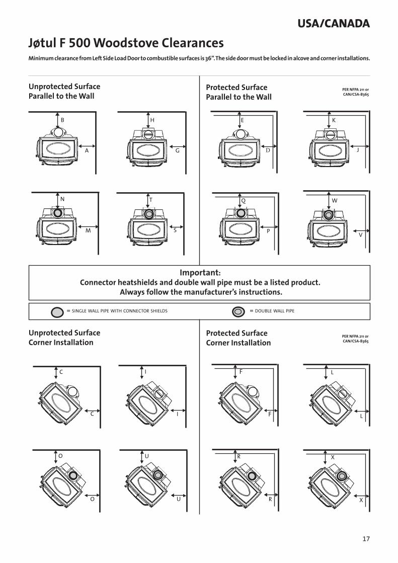
USA/CANADAJøtul F 500 Woodstove Clearances
Unprotected Surface Parallel to the Wall
Protected Surface Parallel to the Wall
Unprotected SurfaceCorner Installation
Protected Surface Corner Installation
E
F
G
H
C F
A
K
L
M
N
O
P
Q
R
B
I
I L
O R
S
T
U
V
W
XU
X
D
PER NFPA 211 or CAN/CSA-B365
PER NFPA 211 or CAN/CSA-B365
Important:Connector heatshields and double wall pipe must be a listed product.
Always follow the manufacturer’s instructions.
= SINGLE WALL PIPE WITH CONNECTOR SHIELDS = DOUBLE WALL PIPE
J
C
Minimum clearance from Left Side Load Door to combustible surfaces is 36”. The side door must be locked in alcove and corner installations.
18
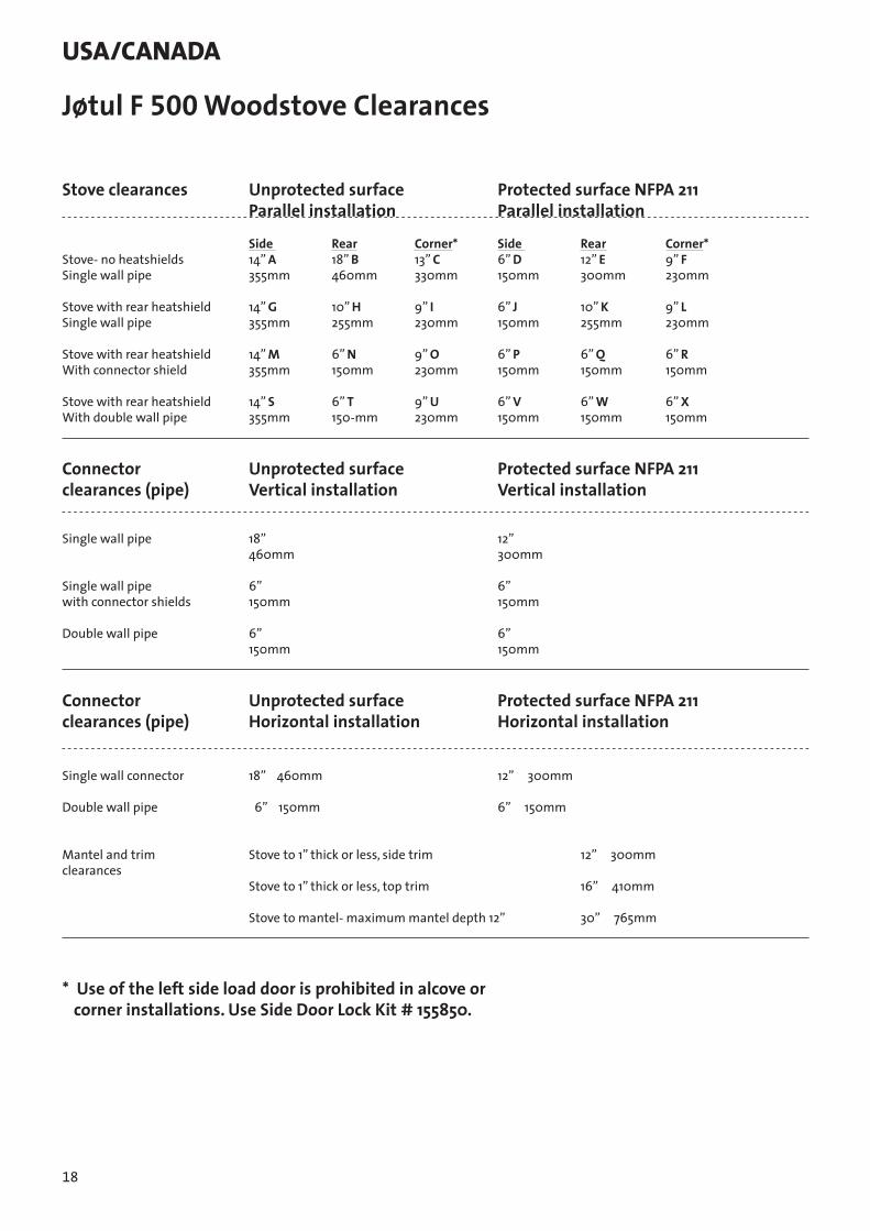
Stove clearances Unprotected surface Protected surface NFPA 211 Parallel installation Parallel installation
Side Rear Corner* Side Rear Corner* Stove- no heatshields 14” A 18” B 13” C 6” D 12” E 9” F Single wall pipe 355mm 460mm 330mm 150mm 300mm 230mm Stove with rear heatshield 14” G 10” H 9” I 6” J 10” K 9” L Single wall pipe 355mm 255mm 230mm 150mm 255mm 230mm Stove with rear heatshield 14” M 6” N 9” O 6” P 6” Q 6” R With connector shield 355mm 150mm 230mm 150mm 150mm 150mm Stove with rear heatshield 14” S 6” T 9” U 6” V 6” W 6” X With double wall pipe 355mm 150-mm 230mm 150mm 150mm 150mm Connector Unprotected surface Protected surface NFPA 211 clearances (pipe) Vertical installation Vertical installation
Single wall pipe 18” 12” 460mm 300mm Single wall pipe 6” 6” with connector shields 150mm 150mm Double wall pipe 6” 6” 150mm 150mm Connector Unprotected surface Protected surface NFPA 211 clearances (pipe) Horizontal installation Horizontal installation Single wall connector 18” 460mm 12” 300mm Double wall pipe 6” 150mm 6” 150mm Mantel and trim Stove to 1” thick or less, side trim 12” 300mm clearances Stove to 1” thick or less, top trim 16” 410mm Stove to mantel- maximum mantel depth 12” 30” 765mm
* Use of the left side load door is prohibited in alcove or corner installations. Use Side Door Lock Kit # 155850.
Jøtul F 500 Woodstove Clearances
USA/CANADA

19
USA/CANADA
27
65 1
1
71 1
1 448 1
50 3
60 1
56 1 39 1
62 1
6 1
7 1
24 145 230 2
72 173 2 20 1 22 1
45 443 4 31 1
45 145 2
31 2
12 1
2 129 140 150 136 1
51 1
37 1 52 1
41 1
83 146 1
53 1
54 2 25 116 1 47 145 2
33 2
44 2
59 1 63 1 75 144 4
34 244 4
8 1
57 1
3 1
9 1 64 1
70 4
45 2
10 1
11 1
5 1
67 1 29 2
76 1 77 1 29 374 2
32 261 2
81 1
19 145 333 2
33 3
30 2
21 1
23 1
28 1
14 133 1
49 168 1
79 435 4
54 237 1
58 1 44 141 1
DEL
-LIS
TE/P
ART
LIST
Jøtu
l F50
0
52 1
Dra
win
g n
o.3-
2713
-P06
40 150 1
17 180 1
29 1
4 1
53 146 1
82 183 1
Jøtu
l AS
Fred
riks
tad
, Nor
way
36 178 1
38 169 1
44 2
Dat
e:D
ec 2
00818 1
15 1
26 266 2 42 245 2
13 1
45 233 2
84
60 56
8253
Res.
del
er k
omp
l.
Spar
e p
arts
com
pl.
185
144
86 1
20
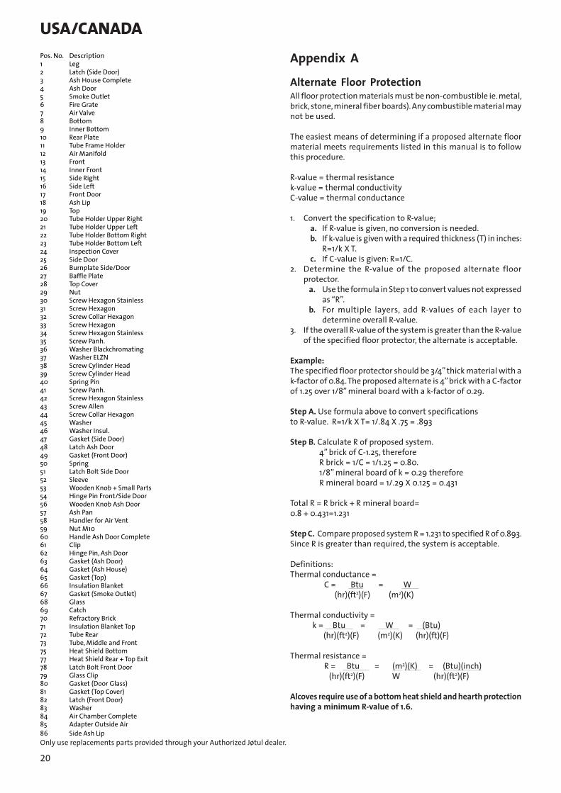
Appendix AAlternate Floor ProtectionAll floor protection materials must be non-combustible ie. metal, brick, stone, mineral fiber boards). Any combustible material may not be used.
The easiest means of determining if a proposed alternate floor material meets requirements listed in this manual is to follow this procedure.
R-value = thermal resistancek-value = thermal conductivityC-value = thermal conductance
1. Convert the specification to R-value;a. If R-value is given, no conversion is needed.b. If k-value is given with a required thickness (T) in inches:
R=1/k X T.c. If C-value is given: R=1/C.
2. Determine the R-value of the proposed alternate floor protector.
a. Use the formula in Step 1 to convert values not expressed as “R”.
b. For multiple layers, add R-values of each layer to determine overall R-value.
3. If the overall R-value of the system is greater than the R-value of the specified floor protector, the alternate is acceptable.
Example:The specified floor protector should be 3/4” thick material with a k-factor of 0.84. The proposed alternate is 4” brick with a C-factor of 1.25 over 1/8” mineral board with a k-factor of 0.29.
Step A. Use formula above to convert specifications to R-value. R=1/k X T= 1/.84 X .75 = .893
Step B. Calculate R of proposed system. 4” brick of C-1.25, therefore R brick = 1/C = 1/1.25 = 0.80. 1/8” mineral board of k = 0.29 therefore R mineral board = 1/.29 X 0.125 = 0.431
Total R = R brick + R mineral board= 0.8 + 0.431=1.231
Step C. Compare proposed system R = 1.231 to specified R of 0.893. Since R is greater than required, the system is acceptable.
Definitions:Thermal conductance = C = Btu = W (hr)(ft2)(F) (m2)(K)
Thermal conductivity = k = Btu = W = (Btu) (hr)(ft2)(F) (m2)(K) (hr)(ft)(F)
Thermal resistance = R = Btu = (m2)(K) = (Btu)(inch) (hr)(ft2)(F) W (hr)(ft2)(F)
Alcoves require use of a bottom heat shield and hearth protection having a minimum R-value of 1.6.
Only use replacements parts provided through your Authorized Jøtul dealer.
Pos. No. Description1 Leg 2 Latch (Side Door)3 Ash House Complete4 Ash Door 5 Smoke Outlet 6 Fire Grate7 Air Valve8 Bottom9 Inner Bottom 10 Rear Plate11 Tube Frame Holder 12 Air Manifold 13 Front14 Inner Front 15 Side Right16 Side Left17 Front Door18 Ash Lip19 Top 20 Tube Holder Upper Right 21 Tube Holder Upper Left22 Tube Holder Bottom Right 23 Tube Holder Bottom Left24 Inspection Cover 25 Side Door26 Burnplate Side/Door 27 Baffle Plate 28 Top Cover 29 Nut 30 Screw Hexagon Stainless31 Screw Hexagon 32 Screw Collar Hexagon33 Screw Hexagon 34 Screw Hexagon Stainless35 Screw Panh.36 Washer Blackchromating37 Washer ELZN38 Screw Cylinder Head39 Screw Cylinder Head40 Spring Pin41 Screw Panh.42 Screw Hexagon Stainless43 Screw Allen44 Screw Collar Hexagon 45 Washer46 Washer Insul.47 Gasket (Side Door)48 Latch Ash Door49 Gasket (Front Door)50 Spring51 Latch Bolt Side Door52 Sleeve 53 Wooden Knob + Small Parts54 Hinge Pin Front/Side Door56 Wooden Knob Ash Door57 Ash Pan58 Handler for Air Vent59 Nut M1060 Handle Ash Door Complete61 Clip62 Hinge Pin, Ash Door63 Gasket (Ash Door)64 Gasket (Ash House)65 Gasket (Top) 66 Insulation Blanket67 Gasket (Smoke Outlet)68 Glass 69 Catch 70 Refractory Brick71 Insulation Blanket Top72 Tube Rear 73 Tube, Middle and Front75 Heat Shield Bottom77 Heat Shield Rear + Top Exit78 Latch Bolt Front Door79 Glass Clip80 Gasket (Door Glass)81 Gasket (Top Cover)82 Latch (Front Door) 83 Washer84 Air Chamber Complete85 Adapter Outside Air86 Side Ash Lip
USA/CANADA

21
9.0 Jøtul N. A. wood-burning product limited warrantyEffective February 1, 2010
This warranty policy applies to wood-burning products identified by Jøtul and Scan trade names, as set forth below.
A. Cast Iron, Enamel, and Steel Components:Jøtul North America Inc. (JØTUL) warrants, to the original retail purchaser, that those components of the Jøtul or Scan Stove or Fireplace specified above will be free of defects in material and workmanship for a period of five (5) years from the date of purchase. This warranty is subject to the terms, exclusions and limitations set forth in the following text.
B. Electrical Components (blowers, thermostatic switches): JØTUL warrants, to the original retail purchaser, that those components of the Jøtul or Scan Stove or Fireplace specified above will be free of defects in material and workmanship for a period of one (1) year from the date of purchase. This warranty is subject to the terms, exclusions, and limitations set forth in the following text
JØTUL will repair or replace (including parts & labor), at its option, any of the above components determined by JØTUL to be covered by this warranty. You must, at your own expense, arrange to deliver or ship the component to an authorized Jøtul or Scan dealer and arrange for pickup or delivery of the component after repairs have been made. If, upon inspection, JØTUL determines that the component is covered by this warranty, the repair or replacement will be made as set forth above. This warranty is not transferable and is extended only to, and is solely for the benefit of, the original retail purchaser of the Jøtul or Scan Stove or Fireplace. This paragraph sets forth the sole remedy available under this warranty in the event of any defect in the Jøtul or Scan Stove or Fireplace.
The warranty period for any replaced component will be the remaining unexpired portion of the warranty period for the original component.
Please retain your dated sales receipt in your records as proof of purchase.
Exclusions and limitationsNotice: This warranty is void if installation or service is performed by someone other than an authorized installer or service agency, or if installation is not in conformance with the installation and operating instructions contained in this owner’s manual or local and/or national fire and building regulations. A listing of local authorized installers, service agencies and gas suppliers can be obtained from the National Fireplace Institute at http://www.nficertified.org/.
This warranty does not cover the following:1. Repair or replacement of parts that are subject to normal
wear and tear during the warranty period or to parts that may require replacement in connection with normal maintenance. These parts include paint, gaskets, burn plates, baffles, air manifolds, firebricks, fire grates, or glass (glass is only warranted against thermal breakage).
2. Damage due to incorrect installations not in conformance with the installation instructions contained in this owner’s manual or local and/or national fire and building regulations.
3. Damage, including damage to enamel surfaces, caused by improper operation, over-firing, and/or misuse. Improper operation, such as burning the stove with the ash door open, can damage the stove. Over-firing occurs when any part of the stove glows red. Over-firing can also be identified by warped plates, rust-colored cast iron, paint pigment that has turned dusty white, or bubbling, cracking and discoloration of the enamel finish. Misuse includes, without limitation, use that is not in conformance with the operating instructions contained in this owner’s manual.
4. Damage due to service performed by an installer or service agency, unless otherwise agreed to in writing by JØTUL.
5. Damage caused by unauthorized modification, use or repair.6. Costs incurred by travel time and/or loss of service.7. Labor or other costs associated with the repair of components
beyond the warranty period.8. Damage incurred while the Jøtul or Scan Stove or Fireplace
is in transit.
IN NO EVENT SHALL JØTUL, ITS PARENT COMPANY, SHAREHOLDERS, AFFILIATES, OFFICERS, EMPLOYEES, AGENTS OR REPRESENTATIVES BE LIABLE OR RESPONSIBLE TO YOU FOR ANY SPECIAL, INDIRECT, INCIDENTAL, CONSEQUENTIAL, PUNITIVE OR OTHER SIMILAR DAMAGES, INCLUDING, BUT NOT LIMITED TO, LOST PROFITS, LOST SALES, INJURY TO PERSON OR PROPERTY, OR DAMAGES TO A STRUCTURE OR ITS CONTENTS, ARISING UNDER ANY THEORY OF LAW WHATSOEVER. ALL IMPLIED WARRANTIES, INCLUDING THE IMPLIED WARRANTIES OF MERCHANTABILITY AND FITNESS FOR A PARTICULAR PURPOSE, OR OTHERWISE, ARE LIMITED IN DURATION TO THE LENGTH OF THIS WRITTEN WARRANTY. EXCEPT AS EXPRESSLY SET FORTH HEREIN, JØTUL MAKES NO ORAL, WRITTEN OR OTHER WARRANTY WITH RESPECT TO JØTUL OR SCAN STOVES OR FIREPLACES.
Some states do not allow the exclusion or limitation of incidental or consequential damages, or limitations on the length of implied warranties. Therefore, the above exclusions or limitations may not apply to you. This warranty gives you specific legal rights, and you may have other rights, which vary from state to state.
JØTUL reserves the right to discontinue, modify or change the materials used to produce the Jøtul or Scan Stove or Fireplace. JØTUL shall have the right to replace any defective component with substitute components determined by JØTUL to be of substantially equal quality and price.

22
The dollar value of JØTUL’s liability for breach of this warranty shall be limited exclusively to the cost of furnishing a replacement component. JØTUL shall not in any event be liable for the cost of labor expended by others in connection with any defective component. Any costs or expenses beyond those expressly assumed by JØTUL under the terms of this warranty shall be the sole responsibility of the owner(s) of the Jøtul or Scan Stove or Fireplace.
No dealer, distributor, or other person is authorized to modify, augment, or extend this limited warranty on behalf of JØTUL. NO MODIFICATION OR CHANGE TO THIS WARRANTY WILL BE EFFECTIVE UNLESS IT IS MADE IN A WRITTEN DOCUMENT MANUALLY SIGNED BY AN AUTHORIZED OFFICER OF JØTUL.
An authorized installer may have been provided with certain information related particularly to the Jøtul or Scan Stove or Fireplace; however, no authorized installer or other person who may service the appliance is an agent of JØTUL. No inference should be made that JØTUL has tested, certified, or otherwise pronounced any person as qualified to install or service the appliance. JØTUL shall not be liable or otherwise responsible for any error or omission by a person installing or servicing a Jøtul or Scan Stove or Fireplace.
If you believe your Jøtul or Scan Stove or Fireplace is defective, you should contact your nearest authorized Jøtul or Scan dealer, who will process a warranty claim. IN ORDER TO QUALIFY FOR WARRANTY COVERAGE, JØTUL MUST RECEIVE NOTICE OF A POSSIBLE DEFECT WITHIN SIXTY (60) DAYS OF THE DATE THE DEFECT IS FIRST DISCOVERED, OR REASONABLY COULD HAVE BEEN DISCOVERED.
This warranty is given by Jøtul North America, Inc., 55 Hutcherson Drive, Gorham, Maine 04038 USA
23
Jøtul pursue a policy of constant product development. Products supplied may therefore differ in specification, colour and type of accessories from those illustrated and described in the brochure.
QualityJøtul AS has a quality system that conforms to NS-EN ISO 9001 for product development, manufacturing, and distribution of stoves and fireplaces. This policy gives our customers quality and safety piece of mind as a result of Jøtul’s vast experience dating back to when the company first started in 1853.
Cat.no. 10024553 (129507)Draw
.no. 4-3492-P15
Møklegaards Trykkeri AS, Jan, 2011
Jøtul North America Inc.55 Hutcherson DriveGorham, Maine 04038USA
Jøtul AS P.o. box 1411N-1602 Fredrikstad, Norway


