Comparison between double pulse and multipulse differential techniques Angela Molina a,⇑ , Eduardo Laborda a , Francisco Martínez-Ortiz a , Dan F. Bradley b , David J. Schiffrin b , Richard G. Compton c,⇑ a Departamento de Química Física, Universidad de Murcia, Espinardo 30100, Murcia, Spain b Department of Chemistry, University of Liverpool, Liverpool, L69 7ZD, United Kingdom c Department of Chemistry, Physical and Theoretical Chemistry Laboratory, Oxford University, South Parks Road, Oxford, OX1 3QZ, United Kingdom article info Article history: Received 20 February 2011 Received in revised form 7 April 2011 Accepted 12 April 2011 Available online 20 April 2011 Keywords: Differential double pulse voltammetry Differential multipulse voltammetry Square wave voltammetry Slow charge transfer processes Microelectrodes abstract The most common differential pulse techniques are analyzed and their responses are compared. Depend- ing on whether or not the initial conditions are re-established before the application of each double pulse we distinguish between double pulse and multipulse differential techniques. The nomenclature employed in the literature is clarified to avoid future confusion. The differences and similarities between the double pulse and multipulse responses are studied for electrode processes of any degree of reversibility, analysing the advantages and disadvantages of each method. The effect of the electrode size is also discussed, establishing the conditions under which the vol- tammograms obtained by different techniques are coincident or not. Ó 2011 Elsevier B.V. All rights reserved. 1. Introduction Differential Pulse Voltammetry (DPV) is a very popular pulse technique due to its high sensitivity, the high resolution of the peak-shaped response and the minimization of double layer and background effects [1–3]. These properties partially come from the subtractive nature of the technique where the signal is given by the difference between currents recorded at the end of consec- utive potential pulses, resulting in a peak-shaped voltammogram. In addition, given that it is a pulse technique and the value of the applied potential remains constant during each pulse, the effect of the charging current is greatly reduced since this sharply decays after the application of the pulse. As a consequence, the DPV tech- nique is widely used in electroanalysis for determination of trace elements as well as for the study of electrode processes and iden- tification of reaction mechanisms [1–5]. Currently, two types of waveforms are usually considered when studying or employing the DPV technique: successive double po- tential pulses recovering the initial equilibrium conditions after each one (‘‘double pulse’’ mode, see Fig. 1a) [1,4–8], and a train of pulses superimposed on a staircase waveform (‘‘multipulse’’ mode, see Fig. 1d) [2,9–13]. Thus, in the double pulse technique the theoretical treatment and the interpretation of experimental results are easier, whereas the multipulse variant reduces the duration of the experiments. In general, for both cases in each pair of potential pulses the length of the first pulse is much longer than the second one. As will be discussed in this paper, the voltammograms obtained with these two potential waveforms are not equivalent and so it becomes necessary to clearly distinguish between them in order to avoid misinterpretation of experimental data. Unfortunately, there is some disagreement in the literature about the terminology employed with the DPV technique. Thus, the term ‘‘Differential Pulse Voltammetry’’ (DPV) referring to the ‘‘double pulse’’ program has been used in the literature [1,4–8], whereas other authors and most of the commercial software available in electrochemistry employ the term DPV for the ‘‘multipulse’’ variant [2,9–13]. Some authors [9,14] have used the term ‘‘Differential Pulse Polarogra- phy’’ (DPP) for the ‘‘double pulse’’ mode, in reminiscence of the use of mercury drop electrodes where the drop is dislodged after each double pulse [15–19]. Nevertheless, this technique is not restricted to mercury electrodes but it can be, and often is, carried out at stationary nonpolarographic electrodes so that, from our point of view, the term DPP is best avoided hereafter. Indeed, Osteryoung et al. recommended the use of the term ‘‘polar- ography’’ for the dropping mercury electrode and the term ‘‘voltammetry’’ for the static mercury drop and solid electrodes [20]. Therefore, in this work we suggest and employ the term 1572-6657/$ - see front matter Ó 2011 Elsevier B.V. All rights reserved. doi:10.1016/j.jelechem.2011.04.012 ⇑ Corresponding authors. Tel.: +34 868 88 7524; fax: +34 868 88 4148 (A. Molina), tel.: +44(0) 1865 275413; fax: +44(0) 1865 275410 (R.G. Compton). E-mail addresses: [email protected](A. Molina), [email protected](R.G. Compton). Journal of Electroanalytical Chemistry 659 (2011) 12–24 Contents lists available at ScienceDirect Journal of Electroanalytical Chemistry journal homepage: www.elsevier.com/locate/jelechem
Transcript
Journal of Electroanalytical Chemistry 659 (2011) 12–24
Contents lists available at ScienceDirect
Journal of Electroanalytical Chemistry
journal homepage: www.elsevier .com/locate / je lechem
Comparison between double pulse and multipulse differential techniques
Angela Molina a,⇑, Eduardo Laborda a, Francisco Martínez-Ortiz a, Dan F. Bradley b,David J. Schiffrin b, Richard G. Compton c,⇑a Departamento de Química Física, Universidad de Murcia, Espinardo 30100, Murcia, Spainb Department of Chemistry, University of Liverpool, Liverpool, L69 7ZD, United Kingdomc Department of Chemistry, Physical and Theoretical Chemistry Laboratory, Oxford University, South Parks Road, Oxford, OX1 3QZ, United Kingdom
a r t i c l e i n f o a b s t r a c t
Article history:Received 20 February 2011Received in revised form 7 April 2011Accepted 12 April 2011Available online 20 April 2011
The most common differential pulse techniques are analyzed and their responses are compared. Depend-ing on whether or not the initial conditions are re-established before the application of each double pulsewe distinguish between double pulse and multipulse differential techniques. The nomenclatureemployed in the literature is clarified to avoid future confusion.
The differences and similarities between the double pulse and multipulse responses are studied forelectrode processes of any degree of reversibility, analysing the advantages and disadvantages of eachmethod. The effect of the electrode size is also discussed, establishing the conditions under which the vol-tammograms obtained by different techniques are coincident or not.
� 2011 Elsevier B.V. All rights reserved.
1. Introduction
Differential Pulse Voltammetry (DPV) is a very popular pulsetechnique due to its high sensitivity, the high resolution of thepeak-shaped response and the minimization of double layer andbackground effects [1–3]. These properties partially come fromthe subtractive nature of the technique where the signal is givenby the difference between currents recorded at the end of consec-utive potential pulses, resulting in a peak-shaped voltammogram.In addition, given that it is a pulse technique and the value of theapplied potential remains constant during each pulse, the effectof the charging current is greatly reduced since this sharply decaysafter the application of the pulse. As a consequence, the DPV tech-nique is widely used in electroanalysis for determination of traceelements as well as for the study of electrode processes and iden-tification of reaction mechanisms [1–5].
Currently, two types of waveforms are usually considered whenstudying or employing the DPV technique: successive double po-tential pulses recovering the initial equilibrium conditions aftereach one (‘‘double pulse’’ mode, see Fig. 1a) [1,4–8], and a trainof pulses superimposed on a staircase waveform (‘‘multipulse’’
mode, see Fig. 1d) [2,9–13]. Thus, in the double pulse techniquethe theoretical treatment and the interpretation of experimentalresults are easier, whereas the multipulse variant reduces theduration of the experiments. In general, for both cases in each pairof potential pulses the length of the first pulse is much longer thanthe second one.
As will be discussed in this paper, the voltammograms obtainedwith these two potential waveforms are not equivalent and so itbecomes necessary to clearly distinguish between them in orderto avoid misinterpretation of experimental data. Unfortunately,there is some disagreement in the literature about the terminologyemployed with the DPV technique. Thus, the term ‘‘DifferentialPulse Voltammetry’’ (DPV) referring to the ‘‘double pulse’’ programhas been used in the literature [1,4–8], whereas other authors andmost of the commercial software available in electrochemistryemploy the term DPV for the ‘‘multipulse’’ variant [2,9–13]. Someauthors [9,14] have used the term ‘‘Differential Pulse Polarogra-phy’’ (DPP) for the ‘‘double pulse’’ mode, in reminiscence of theuse of mercury drop electrodes where the drop is dislodged aftereach double pulse [15–19]. Nevertheless, this technique is notrestricted to mercury electrodes but it can be, and often is, carriedout at stationary nonpolarographic electrodes so that, from ourpoint of view, the term DPP is best avoided hereafter.Indeed, Osteryoung et al. recommended the use of the term ‘‘polar-ography’’ for the dropping mercury electrode and the term‘‘voltammetry’’ for the static mercury drop and solid electrodes[20]. Therefore, in this work we suggest and employ the term
Fig. 1. Potential-time programs of the differential pulse techniques considered.
A. Molina et al. / Journal of Electroanalytical Chemistry 659 (2011) 12–24 13
‘‘Differential Double Pulse Voltammetry’’ (DDPV) [21] for the dou-ble pulse mode (Fig. 1a) and ‘‘Differential Multi Pulse Voltamme-try’’ (DMPV) for the multipulse mode (Fig. 1d). With thisconvention both modes can be immediately distinguished andthe generality of the electrochemical methods is not impaired.
A new problem arises when the durations of the two pulses ineach pair of pulses are similar, which complicates the mathemati-cal resolution of the problem with respect to DDPV. This situationhas traditionally been referred as ‘‘normal’’ mode [3,6,7] and fol-lowing this criterion we propose the term Differential Double Nor-mal Pulse Voltammetry (DDNPV) and Differential Normal MultiPulse Voltammetry (DNMPV) for these variants of the DDPV andDMPV methods, respectively, when t1 � t2 (Fig. 1b and e). Note thatSquare Wave Voltammetry can be viewed as a particular case ofthe DNMPV technique when t1 = t2 and the pulse height is oppositefrom the scan direction (Fig. 1f), and for the analogous double pulsetechnique we suggest the term Double Pulse Square Wave Voltam-metry (Fig. 1c).
According to the above, the aim of this paper is to analyze thedifferences and similarities between differential double pulsetechniques and differential multipulse techniques for differentconditions of electrode kinetics, pointing out the sources ofdiscrepancy or similarity. When the responses significantlydiffer, the advantages and disadvantages of each method arediscussed.
The effect of the electrode size is also analyzed, showing thatthe differences between double pulse and multipulse techniquesdecrease with the electrode radius. The maximum value ofthe electrode radius to obtain equivalent DI � E responses isestablished.
2. Differential pulse techniques: potential-time program
The techniques considered in this work are all differential pulsetechniques based on sampling the current at the end of consecutivepotential pulses and plotting the current difference versus a poten-tial axis, which gives rise to a peak-shaped response [1–3].
Depending on whether or not the initial conditions are regainedbefore the application of each double pulse we can distinguish be-tween double pulse and multipulse differential techniques.
2.1. Differential double pulse techniques
In double pulse techniques the initial, equilibrium conditionsare re-established before the application of each double pulse(see Fig. 1a–c) so that there are no accumulative effects.
At stationary electrodes, the renewal of the initial conditionscan be attained by open circuiting the working electrode[22,23] or by setting the applied potential at an adequate initialvalue [6] for a waiting period. Commercial instrumentation[24,25] enables to implement this potential-time program bydesigning a program of successive double potential step chrono-amperometries with a delay time with cell off after each one. Thisfact greatly simplifies the theoretical treatment of the techniqueas well as the interpretation of the experimental results sinceeach double pulse is independent of the previous ones such thatanalytical solutions are available for the direct study of theresponse (see Appendix A). On the other hand, the recording ofa complete voltammogram is slower than with multipulsetechniques.
2.1.1. Differential Double Pulse Voltammetry (DDPV)In DDPV the length of the second pulse (t2) is much shorter than
the length of the first pulse (t1), t1/t2 = 50 � 100 (Fig. 1a), whichleads to very high sensitivity and further simplification of themathematical treatment so that a very simple analytical expres-sion is available for the analysis of the experimental results (seeAppendix A).
2.1.2. Differential Double Normal Pulse Voltammetry (DDNPV)In this case both pulses have similar durations t1 � t2 (Fig. 1b)
which notably complicates the resolution of the problem andtherefore the form of the analytical solution (see Appendix A).The shape of the response is also affected such that in DDNPV an
14 A. Molina et al. / Journal of Electroanalytical Chemistry 659 (2011) 12–24
asymmetric peak is obtained with the signal tending to a non-nullconstant value for limiting current conditions.
2.1.3. Double Pulse Square Wave Voltammetry (DPSWV)This is a particular case of DDNPV where the durations of both
pulse are equal t1 = t2 and the pulse height (DE = E2 � E1) is oppo-site from the scan direction (Fig. 1c). Because of its analogy withthe potential-time program applied in Square Wave Voltammetry,we will refer to this technique as Double Pulse Square WaveVoltammetry.
2.2. Differential multipulse techniques
In multipulse techniques there is no renewal of the initial con-ditions during the experiment and so progressive depletion of theelectroactive species and accumulation of the electrode productcan take place near the electrode surface, consequently affectingthe electrochemical response.
For these techniques, analytical solutions are not available ex-cept for reversible processes since for quasireversible and irrevers-ible ones the superposition principle does not apply and thereforeit has not been possible to deduce explicit general analyticalexpressions for multipulse techniques [26]. Accordingly, for suchsystems, we have employed numerical methods with proceduresand conditions described in Appendix A.
2.2.1. Differential Multi Pulse Voltammetry (DMPV)The DMPV technique can be viewed as a variant of DDPV where
the initial conditions are not recovered during the experiment(Fig. 1d). Thus, the pulse length (tp) is much shorter than the periodbetween pulses (t1), t1/tp = 50 � 100.
2.2.2. Differential Normal Multi Pulse Voltammetry (DNMPV)The DNMPV is the multipulse variant of the DMPV technique
such that the duration of the period between pulses and the dura-tion of the pulses are similar: t1 � tp (Fig. 1e).
2.2.3. Square Wave Voltammetry (SWV)The well-known Square Wave Voltammetry can be considered
as a particular situation of DNMPV where the length of both pulsesare equal (t1 = tp) and the sign of the pulse height (DE) is oppositefrom the scan direction (Fig. 1f).
3. Results and discussion
The comparison of the double pulse techniques DDPV, DDNPVand DPSWV with respect to their corresponding multipulse vari-ants DMPV, DNMPV and SWV was carried out for a wide range ofconditions. In general, the similarity or difference between the re-sponses reflects the significance of the accumulative effects thattakes place in the multipulse techniques, in other words, the abilityof the system to lose the ‘‘memory’’ of the previous pulses. This willobviously depend on the reversibility of the electrode process, themass transport (i.e., on the electrode size) and the relative durationof the potential pulses.
For the results corresponding to double pulse techniques, Eqs.(A4), (A5), (A13), and (A14) presented in Appendix A are used, bymaking r0 ?1 in the case of planar electrodes. For multipulsetechniques, Eqs. (A8) and (A9) are employed for reversible pro-cesses, whereas for slow charge transfer processes we have usednumerical methods as described in the same Appendix A.
3.1. Comparison of double pulse and multipulse differential techniquesfor different electrode kinetics
In Figs. 2–4 the responses of the three general cases: reversible,quasireversible and irreversible processes are considered in thedifferent techniques. Note that t2 refers to the length of the secondpulse of each pair of pulses in double pulse techniques and tp to thelength of each pulse in multipulse techniques (see Fig. 1).
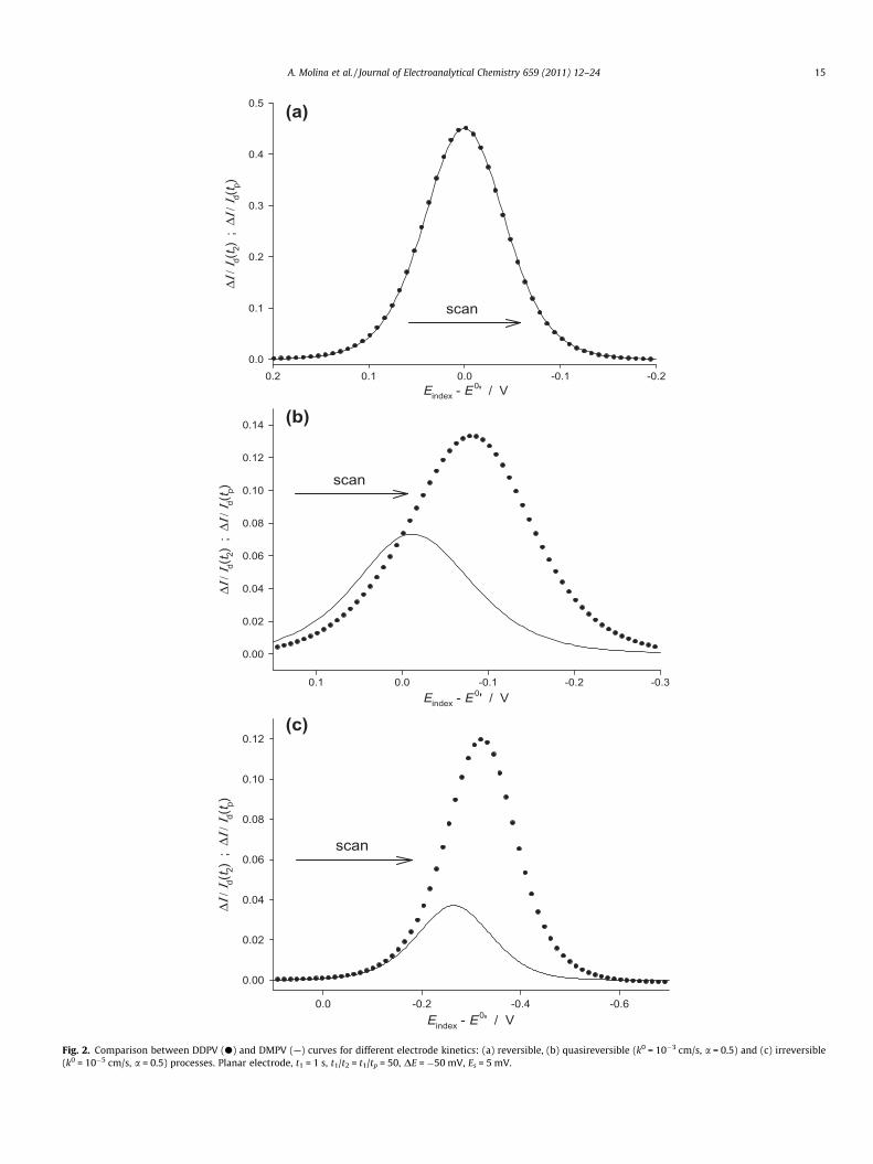
Fig. 2 shows the voltammograms corresponding to the doublepulse and multipulse techniques where the duration of the pulsesare such that t1� t2 and t1� tp, that is, DDPV and DMPV. As can beobserved in Fig. 2a, the responses of reversible processes in bothtechniques are totally coincident as the electrode process is fastand the period between pulses (t1) is much longer than the lengthof the pulse (tp), since in DMPV the system is able to establish con-ditions equivalent to DDPV near the electrode surface during thefirst period as if previous pulses had not existed. Therefore, underthese conditions (reversible processes and very short pulse period),we can take advantage of the simple analytical expression avail-able for DDPV (Appendix A) together with the faster potential-timeprogram of DMPV.
In Figs. 3 and 4 the voltammograms obtained considering sim-ilar durations of the potential pulses (t1 = t2, t1 = tp) are shown. Inthis case, the difference between the responses for reversible pro-cesses (Figs. 3a and 4a) is significant since the distortion of the pre-vious pulses cannot be removed during the first period and, as aconsequence, the double pulse and multipulse voltammogramsare not coincident.
The results shown in Figs. 2a and 3a are in line with those pre-viously reported for the case of reversible processes [9,27] accord-ing to which the period between pulses must be at least five timeslonger that the pulse so that the agreement between the DDPV andDMPV voltammograms when t1/tp = 50 � 100 is excellent whereaswhen t1 = tp important differences are found. Nevertheless, as weindicated at the beginning of this section, the electrode kineticswill have a major effect on the relationship between double pulseand multipulse responses and so the conclusions inferred forreversible processes cannot be extended to slow charge transferprocesses.
In Figs. 2b, 2c, 3b, 3c, 4b and 4c the comparison betweendouble pulse and multipulse techniques for quasireversible andirreversible processes is analyzed. Unlike reversible processes,for sluggish electrode reactions the disagreement between thecurves is apparent whatever the length of the pulses, the slowerthe charge transfer, the greater the discrepancy of the curves.This affects not only to the value of the peak current but alsoto the position of the peak such that the curves correspondingto the multipulse methods (DMPV, DNMPV and SWV) appear atless negative potentials.
As was mentioned above, the discrepancy or similarity betweenthe response in double pulse and multipulse techniques is relatedto the ability of the system to compensate the accumulative effectstaking place in the latter. In the case of irreversible charge transferprocesses these effects are more significant since the electrodereaction does not regenerate the electroactive species and so thereis a depletion of the reactant during the scan that gives rise tosmaller signals (see Figs. 2c, 3c and 4c). Thus, for example, thecomparison of the responses in DDPV and DMPV techniques pro-vides a simple diagnosis test for the reversibility of the electrodeprocess (Fig. 2).
According to the above, the electrochemical response in the dif-ferent differential pulse techniques can be very different and it isworth analyzing the advantages and disadvantages of each meth-od. With this aim, in Fig. 5 the voltammograms of the six tech-niques considered in this paper are plotted on the same graphfor reversible and irreversible systems.
(a)
Eindex - E0' / V
-0.2-0.10.00.10.2
Δ Ι /
Ι d(t 2)
; Δ
Ι / Ι d(
t p)
0.0
0.1
0.2
0.3
0.4
0.5
scan
(b)
Eindex - E0' / V
-0.3-0.2-0.10.00.1
Δ Ι /
Ι d(t 2)
; Δ
Ι / Ι d(
t p)
0.00
0.02
0.04
0.06
0.08
0.10
0.12
0.14
scan
(c)
Eindex - E0' / V
-0.6-0.4-0.20.0
Δ Ι /
Ι d(t 2)
; Δ
Ι / Ι d(
t p)
0.00
0.02
0.04
0.06
0.08
0.10
0.12
scan
Fig. 2. Comparison between DDPV (d) and DMPV (—) curves for different electrode kinetics: (a) reversible, (b) quasireversible (k0 = 10�3 cm/s, a = 0.5) and (c) irreversible(k0 = 10�5 cm/s, a = 0.5) processes. Planar electrode, t1 = 1 s, t1/t2 = t1/tp = 50, DE = �50 mV, Es = 5 mV.
A. Molina et al. / Journal of Electroanalytical Chemistry 659 (2011) 12–24 15
Eindex - E0' / V
-0.2-0.10.00.10.2
Δ Ι /
Ι d(t 2)
; Δ
Ι / Ι d(
t p)
-0.4
-0.2
0.0
0.2
0.4
0.6
(b)
Eindex - E0' / V
-0.2-0.10.00.10.2
Δ Ι /
Ι d(t 2)
; Δ
Ι / Ι d(
t p)
-0.2
0.0
0.2
0.4
(a)
(c)
Eindex - E0' / V
-0.6-0.5-0.4-0.3-0.2-0.10.0
Δ Ι /
Ι d(t 2)
; Δ
Ι / Ι d(
t p)
-0.3
-0.2
-0.1
0.0
0.1
0.2
0.3
scan
scan
scan
Fig. 3. Comparison between DDNPV (N) and DNMPV (– –) curves for different electrode kinetics: (a) reversible, (b) quasireversible (k0 = 10�2 cm/s, a = 0.5) and (c) irreversible(k0 = 10�4 cm/s, a = 0.5) processes. t1 = 0.02 s, t1/t2 = t1/tp = 1. Other conditions as in Fig. 2.
16 A. Molina et al. / Journal of Electroanalytical Chemistry 659 (2011) 12–24
Eindex - E0' / V
-0.2-0.10.00.10.2
Δ Ι /
Ι d(t 2)
; Δ
Ι / Ι d(
t p)
-1.0
-0.8
-0.6
-0.4
-0.2
0.0
(a)
scan
(b)
Eindex - E0' / V
-0.3-0.2-0.10.00.10.2
ΔΙ /
Ι d(t 2)
; Δ
Ι / Ι d(
t p)
-0.8
-0.6
-0.4
-0.2
0.0
scan
(c)
Eindex - E0' / V
-0.6-0.4-0.20.00.2
ΔΙ /
Ι d(t 2)
; Δ
Ι / Ι d(
t p)
-0.6
-0.4
-0.2
0.0
scan
Fig. 4. Comparison between DPSWV (D) and SWV (–��–��–) curves for different electrode kinetics: (a) reversible, (b) quasireversible (k0 = 10�2 cm/s, a = 0.5) and(c) irreversible (k0 = 10�4 cm/s, a = 0.5) processes. Planar electrode, t1 = 0.02 s, t1/t2 = t1/tp = 1, DEDPSWV = 2 � ESWV = + 100 mV. Other conditions as in Fig. 2.
A. Molina et al. / Journal of Electroanalytical Chemistry 659 (2011) 12–24 17
Regarding the double pulse methods in normal mode, DDNPVand DPSWV, these have the inconvenience of presenting asymmet-rical peaks that can make difficult the experimental determination
of the peak current. In addition, the peak potential for a reversibleprocess (Fig. 5a) is shifted from the half-wave potential. On theother hand, the other four techniques (DDPV, DMPV, DNMPV and
(b)
Eindex - E 0' / V-0.6-0.4-0.20.00.2
Δ Ι /
Ι d(t 2)
; Δ
Ι / Ι d(
t p)
-0.2
0.0
0.2
0.4
0.6
Eindex - E 0' / V-0.2-0.10.00.10.2
Δ Ι /
Ι d(t 2)
; Δ
Ι / Ι d(
t p)
-0.2
0.0
0.2
0.4
0.6
0.8
1.0 (a)
scan
scan
Fig. 5. Comparison of all the differential pulse techniques for (a) reversible and (b) irreversible (k0 = 10�4 cm/s, a = 0.5) processes: DDPV (d, t1/t2 = 50), DDNPV (N, t1 = t2),DPSWV (D, t1 = t2), DMPV (—, t1/tp = 50), DNMPV (– – –, t1 = tp) and SWV (–��–��–, t1 = tp). In the cases of the DPSWV and SWV techniques the absolute value of the signal (|DI|)is plotted. Planar electrode, t2 = tp = 0.02 s, |DE| = 2 � ESWV = 100 mV, Es = 5 mV.
18 A. Molina et al. / Journal of Electroanalytical Chemistry 659 (2011) 12–24
SWV) have well-defined peaks, all of them centered around thehalf-wave potential in the case of reversible charge transferprocesses.
As can be observed, the choice of the method will depend on theelectrode kinetics of the system under study. Thus, for reversiblesystems the multipulse SWV and DNMPV techniques show greatersensitivity than DDPV and DMPV. For totally irreversible processes,the height of the signal is notably greater in double pulsetechniques than in multipulse ones, and therefore we can inferthat DDPV is the better method for analyzing slow electrodeprocesses because of its higher sensitivity and well-defined curves.Nevertheless, if the aim is to remove the interference of back-ground irreversible signals when studying a reversible processthe multipulse techniques (SWV, DNMPV and DMPV) provides agreater discriminatory power. Note that whatever the revers-ibility degree of the electrochemical process the responses inSWV and DNMPV are in absolute value very similar. Therefore, thesign of the pulse height (opposite or parallel to the scan direction)does not have a significant influence on the electrochemicalresponse.
In previous papers [4,28,29], the striking splitting of the peak-shaped curves for quasireversible processes with small or large val-ues of the transfer coefficient (a) has been described for DDPV andAdditive Differential Pulse Voltammetry. In Fig. 6 the appearanceof this phenomenon in the different differential pulse techniquesis confirmed, which can lead to misinterpretation of experimentaldata by the unwary electrochemist. This effect is more evident inDDPV and multipulse techniques (Fig. 6a) and it is characteristicof sluggish charge transfer processes with a heterogeneous rateconstant of the order k0 � 10�3 � 10�4 cm/s and a < 0.3 for a reduc-tion process and a > 0.7 for an oxidation process.
3.2. Equivalence of the differential techniques at microelectrodes
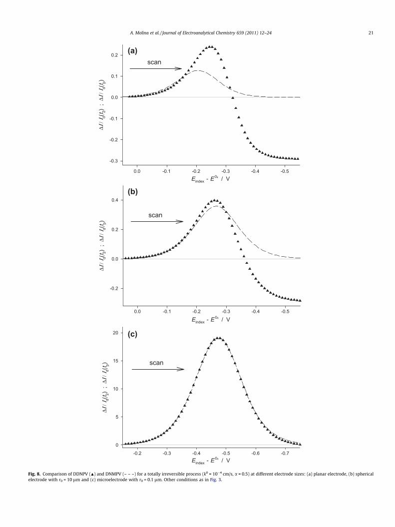
The electrode size is another important factor since it affects themagnitude of the diffusive transport and it is considered in Figs. 7and 8 for totally irreversible processes. At spherical microelec-trodes significant differences are found between double pulseand multipulse modes, the discrepancy diminishing when the elec-trode radius decreases since the system loses the ‘‘memory’’ of the
Eindex - E 0' / V-0.6-0.4-0.20.00.2
Δ Ι /
Ι d(t 2)
; Δ
Ι / Ι d(
t p)
-0.3
-0.2
-0.1
0.0
0.1
0.2
0.3
Eindex - E 0' / V-0.6-0.4-0.20.00.2
Δ Ι /
Ι d(t 2)
; Δ
Ι / Ι d(
t p)
0.00
0.01
0.02
0.03
0.04
k0 (cm/s) = 10 -3
9·10 -4
9·10 -4
2.5·10 -4
k0 (cm/s) = 10 -3
3·10 -4
(a)
scan
scan
(b)
Fig. 6. Splitting of the peak in double pulse and multipulse differential techniques: DDPV (d, t1/t2 = 50), DDNPV (N, t1 = t2), DPSWV (D, t1 = t2), DMPV (—, t1/tp = 50), DNMPV(– – –, t1 = tp) and SWV (–��–��–, t1 = tp). D a = 0.2, k0 values marked on the curves. Planar electrode, t2 = tp = 0.02 s, |DE| = 2 � ESWV = 50 mV, Es = 5 mV.
A. Molina et al. / Journal of Electroanalytical Chemistry 659 (2011) 12–24 19
previous pulses while approaching the stationary response. Thus, itis found that the relative difference in the peak current of a givendouble pulse technique and the corresponding multipulse variantis always smaller than 2% when r0 < 0:1
ffiffiffiffiffiffiffiffiffiffiffipDt1p
. Note that this im-plies that the attainment of equivalent responses requires the useof smaller electrodes when both pulses are short with similarlengths as in DDNPV and DNMPV (see Fig. 8c) than when thelength of the pulse (t2, tp) is much shorter than t1 as in DDPV andDMPV (see Fig. 7c).
Regarding the splitting of the voltammograms described inFig. 6, it is found that this is more apparent at planar electrodes,decreasing when diminishing the electrode radius such that it isnot observed at microelectrodes.
4. Conclusions
A complete analysis of the most usual differential pulse tech-niques has been carried out under very different conditions ofthe electrode kinetics and the electrode size.
Firstly, the disagreement existing about the nomenclature forthese techniques has been pointed out, and a new terminologyhas been proposed in accordance with the pioneering works onthis matter.
Two main variants of the differential methods are distinguishedin function of that the initial conditions are regained before theapplication of each double pulse (double pulse techniques) or not(multipulse techniques). The first alternative enables to simplifythe theoretical treatment of the problem and to avoid accumula-tive effects whereas the second one reduces the time of the exper-iments. It has been found that, in general, the responses of thedouble pulse and multipulse techniques differ significantly at pla-nar electrodes and conventional spherical electrodes, except in thecase of reversible processes with very short pulse durations(t1� tp, t2). On the other hand, when microelectrodes are em-ployed with r0 < 0:1
ffiffiffiffiffiffiffiffiffiffiffipDt1p
the voltammograms are coincidentwhatever the electrochemical reversibility of the process.
Regarding the sensitivity of the different techniques, it has beenshown that the multipulse techniques are more adequate when
(b)
Eindex - E 0' / V-0.6-0.4-0.20.0
ΔΙ /
Ι d(t 2)
; Δ
Ι / Ι d(
t p)
0.00
0.05
0.10
0.15
0.20
Eindex - E 0' / V-0.6-0.4-0.20.0
Δ Ι /
Ι d(t 2)
; Δ
Ι / Ι d(
t p)
0.00
0.02
0.04
0.06
0.08
0.10
0.12 (a)
scan
scan
(c)
Eindex - E 0' / V-0.7-0.6-0.5-0.4-0.3-0.2-0.1
ΔΙ /
Ι d(t 2)
; Δ
Ι / Ι d(
t p)
0.0
0.5
1.0
1.5
2.0 scan
Fig. 7. Comparison between DDPV (d) and DMPV (—) curves for a totally irreversible process (k0 = 10�5 cm/s, a = 0.5) at different electrode sizes: (a) planar electrode, (b)spherical electrode with r0 = 30 lm and (c) microelectrode with r0 = 1 lm. Other conditions as in Fig. 2.
20 A. Molina et al. / Journal of Electroanalytical Chemistry 659 (2011) 12–24
(b)
Eindex - E 0' / V-0.5-0.4-0.3-0.2-0.10.0
Δ Ι /
Ι d(t 2)
; Δ
Ι / Ι d(
t p)
-0.2
0.0
0.2
0.4
(a)
Eindex - E 0' / V-0.5-0.4-0.3-0.2-0.10.0
Δ Ι /
Ι d(t 2)
; Δ
Ι / Ι d(
t p)
-0.3
-0.2
-0.1
0.0
0.1
0.2scan
(c)
Eindex - E 0' / V-0.7-0.6-0.5-0.4-0.3-0.2
ΔΙ /
Ι d(t 2)
; Δ
Ι / Ι d(
t p)
0
5
10
15
20
scan
scan
Fig. 8. Comparison of DDNPV (N) and DNMPV (– – –) for a totally irreversible process (k0 = 10�4 cm/s, a = 0.5) at different electrode sizes: (a) planar electrode, (b) sphericalelectrode with r0 = 10 lm and (c) microelectrode with r0 = 0.1 lm. Other conditions as in Fig. 3.
A. Molina et al. / Journal of Electroanalytical Chemistry 659 (2011) 12–24 21
22 A. Molina et al. / Journal of Electroanalytical Chemistry 659 (2011) 12–24
studying fast charge transfer processes whereas Differential Dou-ble Pulse Voltammetry has a greater sensitivity for irreversibleones.
Acknowledgements
A.M., F.M-O and E.L. greatly appreciate the financial supportprovided by the Dirección General de Investigación (MEC) (ProjectNumber CTQ2009-13023) and by the Fundación SENECA (ProjectNumber 08813/PI/08). Also, E. L. thanks the Ministerio de Cienciae Innovacion for the grant received. DFB and DJS gratefullyacknowledge the support from the European Union (BacWireproject).
Appendix A
A.1. Reversible charge transfer processes
A.1.1. Double pulse techniquesLet us consider a reversible electrode process taking place at a
stationary spherical electrode:
Oþ e��R ðA1Þ
When a double pulse is applied, the potential is set at a value E1
during the first interval 0 6 s1 6 t1, and then (t P t1) it is steppedfrom E1 to E2. The analytical expressions for the current in eachpulse are given by [1–3,30]:
Irev1
FADc�O¼ ð1þ c�R=c�OÞZ1
1r0þ 1ffiffiffiffi
pp
Dt1
� �ðA2Þ
Irev2
FADc�O¼ ð1þ c�R=c�OÞ
X2
n¼1
Zn1ffiffiffiffi
pp
Dtn2
� �þ 1
1þ K2� 1
1þ K0
� �1r0
( )
ðA3Þ
where t12 = t1 + t2 and t22 = t2 and all the variables and functions aregiven in Table 1 and Appendix B.
Hence, according to the definition of the double pulse tech-niques, the signal is obtained from the difference of the currentsat the end of each potential pulse (DIrev ¼ Irev
D Diffusion coefficient ofc�i ; i O;R Bulk concentration of spr0 Radius of the electrodet1 – Duration of the first p
– Duration of the periodt2 Duration of the secondtp Duration of the pulses ikf, kb Heterogeneous rate conk0 Standard heterogeneousa Transfer coefficientE00 Formal potential of the
Eeq ¼ E00 þ RTF lnðc
�O
c�RÞ Equilibrium potential
Ep Potential applied duringDE Pulse height in DDPV, DESWV Pulse height in SWVEs Staircase step height
Eindex ¼ E1þE22
Index potential of the v
Eindex ¼ Einitial � ½Intðpþ12 Þ � 1Es ðp P 1Þ Index potential of the v
DMPV, DNMPV and SWwith: Einitial ¼ E1þE22
When the second pulse is much shorter than the first one (i.e.,in DDPV), the above equation simplifies since it is fulfilled thatt1 + t2 � t1 such that:
DIrevDDPV
FADc�O¼ ð1þ c�R=c�OÞZ2
1r0þ 1ffiffiffiffiffiffiffiffiffiffiffi
pDt2p
� �ðA5Þ
A.1.2. Multipulse techniquesDue to the fact that in this case (reversible processes)
the surface concentrations are independent of time, the super-position principle applies and from Eq. (A3) we can write thefollowing general expression for the current of the pth pulse[22,31]:
Irevp
FADc�O¼ ð1þ c�R=c�OÞ
Xp
n¼1
Zn1ffiffiffiffiffiffiffiffiffiffiffiffiffi
pDtnpp !
þ 11þ Kp
� 11þ K0
� �1r0
( )
ðA6Þ
where:
t ¼ t1p ¼ t1 þ t2 þ . . .þ tp�1 þ tp
tnp ¼ tp þPp�1
m¼ntm
tpp tp
9>>>=>>>;
ðA7Þ
From this general solution, the expressions for the responses inDNMPV and SWV (DIrev ¼ Irev
p � Ip � 1rev) can be immediatelyobtained:
DIrevDNMPV
SWV
FADc�O¼ ð1þ c�R=c�OÞ Zp
1r0þ 1ffiffiffiffiffiffiffiffiffiffiffi
pDtp
p !(
þ 1ffiffiffiffiffiffiffipDp
Xp�1
n¼1
Zn1ffiffiffiffiffiffitnp
p � 1ffiffiffiffiffiffiffiffiffiffitnp�1
p !)
ðA8Þ
In DMPV where the duration of the pulse is much shorter thanthe period between pulses, t1� tp, the solution simplifies since it isfulfilled that tnp � tnp�1 for p� 1:
DIrevDMPV
FADc�O¼ ð1þ c�R=c�OÞZpð
1r0þ 1ffiffiffiffiffiffiffiffiffiffiffi
pDtp
p Þ ðA9Þ
the electroactive speciesecies i
ulse in double pulse techniquesbetween pulses in multipulse techniques
pulse in double pulse techniquesn multipulse techniquesstants of reduction, oxidation processes
rate constant
electroactive couple
the pth pulseDNPV, DPSWV, DMPV and DNMPV
oltammogram in double pulse techniques: DDPV, DDNPV, DPSWV
oltammogram in multipulse techniques:V (where Int (x) is the integer part of the argument, x)
A. Molina et al. / Journal of Electroanalytical Chemistry 659 (2011) 12–24 23
A.2. Slow charge transfer processes
A.2.1. Double pulse techniquesIn this case we consider a slow charge transfer process at a sta-
tionary spherical electrode:
Oþ e� ¢kf
kb
R ðA10Þ
By means of a modification of Koutecky’s dimensionless param-eter method [4,32], this problem has been solved and the expres-sions for the currents of the first and second pulses deduced:
Islow1
FADc�O¼ ðh1 � 1Þð1� c�R=c�OK1Þ
r0h1ð1þ K1Þ1þ ðh1 � 1Þ � 2Fðv01Þffiffiffiffi
pp
v01
� �ðA11Þ
Islow2
FADc�O¼ Islow
1 ðt1 þ t2ÞFADc�O
þ 1ffiffiffiffiffiffiffiffiffiffiffipDt2p 1� 1
h2
� �Sirreðv1;v2Þ þ v2 Xþ u
h2
Fðv1Þv1�
ffiffiffiffipp
2
� �� �� �ðA12Þ
where all the variables and functions are given in Table 1 andAppendix B. From the above equations, the expressions for the re-sponses in DDNPV and DPSWV are derived:
DIslowDDNPVDPSWVFADc�O
¼ 1ffiffiffiffiffiffiffiffipDt2
p fð1� 1h2ÞSirreðv1;v2Þ þ v2½Xþ
uh2ðFðv1Þ
v1�ffiffiffipp
2 Þg
þ 2ðh1�1Þ2ð1�c�R=c�OK1Þffiffiffipp
r0h1ð1þK1ÞFðv1Þv1� Fðv01Þ
v01
h iðA13Þ
When the second pulse is much shorter than the first one theresolution of the problem greatly simplifies since it can be as-sumed that the mathematical form of the solutions for the firstpulse (cð1ÞO ðr; tÞ and cð1ÞR ðr; tÞ) does not change with the applicationof the second pulse [4]. Thus, for the DDPV technique the followingsimple expression is obtained:
DIslowDDPV
FADc�O¼ ðh2 � 1Þf ðv1Þ
r0h2ð1þ K2Þ1þ ðh2 � 1Þ2Fðv2Þffiffiffiffi
pp
v2
� �ðA14Þ
A.2.2. Multipulse techniquesFor charge transfer processes with finite kinetics, the time
dependence of the surface concentrations does not allow to applythe superposition principle and therefore it has not been possibleto deduce explicit analytical solutions for multipulse techniques.
For this case, we have resorted to numerical methods for thesimulation of the response with a homemade program. In this pro-gram we have used an exponentially expanding grid with highexpansion factors and four-point formulae for the discretisationof the spatial derivatives, which warrants very accurate results(four-figure accuracy) with only eight points in the grid for planarelectrodes and 26 points for spherical microelectrodes [33] Regard-ing time-integration, we have used the EXTRAP4 algorithm with 5-time intervals in each potential step that has proven to be veryadequate for pulse techniques where we are only interested inthe response at the end of each potential pulse [34].
According to the above, the method employed gives rise to veryaccurate results with very fast calculation calculations. In addition,it has the great advantage that a Thomas-like algorithm [35] andthe u–v procedure [35,36] for the calculation of surface concentra-tions can be used, which notably simplifies the resolution of theproblem.
24 A. Molina et al. / Journal of Electroanalytical Chemistry 659 (2011) 12–24
References
[1] A.J. Bard, L.R. Faulkner, Electrochemical Methods. Fundamentals andApplications, second ed., Wiley, New York, 2001.
[2] R.G. Compton, C.E. Banks, Understanding Voltammetry, World Scientific,Singapore, 2007.
[3] Z. Galus, Fundamentals of Electrochemical Analysis, second ed., Ellis Horwood,Chichester, 1994.
[4] A. Molina, F. Martínez-Ortiz, E. Laborda, R.G. Compton, Electrochim. Acta 55(2010) 5163.
[5] E. Laborda, F. Martínez-Ortiz, A. Molina, Electroanalysis 22 (2010) 1857.[6] M. Lovric, J.J. O’Dea, J. Osteryoung, Anal. Chem. 55 (1983) 704.[7] K. Aoki, J. Osteryoung, R.A. Osteryoung, J. Electroanal. Chem. 110 (1980) 1.[8] M. Lovric, J. Osteryoung, Electrochim. Acta 27 (1982) 963.[9] M. Lovric, Electroanalysis 11 (1999) 1089.
(1988) 1.[14] M.-H. Kim, L. Yan, R.L. Birke, M.-Z. Czae, Electroanalysis 15 (2003) 1541.[15] G.C. Barker, A.W. Gardner, Z. Anal. Chem. 79 (1960) 173.[16] E.P. Parry, R.A. Osteryoung, Anal. Chem. 37 (1965) 1634.[17] J.B. Flato, Anal. Chem. 44 (1972) 75A.[18] J.E. Anderson, A.M. Bond, R.D. Jones, Anal. Chem. 53 (1981) 1016.[19] N. Fatouros, D. Krulic, J. Chevalet, J. Electroanal. Chem. 364 (1994) 135.
[20] J. Osteryoung, M.M. Schreiner, CRC Crit. Rev. Anal. Chem. 19 (1988) S1.[21] This might lead to confusion with the triple pulse technique Double
Differential Pulse Voltammetry. In order to avoid this, we suggest the termDifferential Triple Pulse Voltammetry (DTPV) for the latter.
[22] A. Molina, E. Laborda, E.I. Rogers, F. Martínez-Ortiz, C. Serna, J.G. Limon-Petersen, N.V. Rees, R.G. Compton, J. Electroanal. Chem. 634 (2009) 73.
[23] E. Laborda, E.I. Rogers, F. Martinez-Ortiz, A. Molina, R.G. Compton, Electrochim.Acta 55 (2010) 6577.
[24] www.ecochemie.nl/index.html.[25] www.ivium.nl.[26] A. Molina, C. Serna, L. Camacho, J. Electroanal. Chem. 394 (1995) 1.[27] D. Krulic, N. Fatouros, M.M. El Belamachi, J. Electroanal. Chem. 385 (1995) 33.[28] H. Matsuda, Bull. Chem. Soc. Jpn. 53 (1980) 3439.[29] E. Laborda, E.I. Rogers, F. Martínez-Ortiz, A. Molina, R.G. Compton,
Electroanalysis 22 (2010) 2784.[30] C. Serna, A. Molina, J. Electroanal. Chem. 466 (1999) 8.[31] A. Molina, J. González, F. Martínez-Ortiz, R.G. Compton, J. Phys. Chem. C 114
(2010) 4093.[32] E. Laborda, Study of different electrode processes by double potential pulse
techniques at spherical electrodes and microelectrodos, Thesis dissertation,University of Murcia, 2010.
[33] F. Martínez-Ortiz, N. Zoroa, A. Molina, C. Serna, E. Laborda, Electrochim. Acta54 (2009) 1042.
[34] F. Martínez-Ortiz, A. Molina, E. Laborda, Electrochim. Acta, Submitted.[35] D. Britz, Digital Simulation in Electrochemistry, third ed., Springer, Berlin, 2005.[36] D. Britz, J. Electroanal. Chem. 352 (1993) 17.