Huazhen Fanga,*, Christopher Depcika, Vadim Lvovichb
aDepartment of Mechanical Engineering, University of Kansas, Lawrence, KS 66045, USAbNASA John H. Glenn Research Center, Cleveland, OH 44135, USA
A R T I C L E I N F O
Article history:Received 29 July 2017Received in revised form 7 November 2017Accepted 8 November 2017Available online 7 February 2018
Keywords:Pulse chargingCharging managementBattery managementFast chargingControl theory
A B S T R A C T
This paper focuses on the development of optimized pulse charging strategies for Lithium-ion (Li-ion)batteries. Aiming to improve the constant pulse charging in wide use today, we propose for the first timeto modulate the current pulses during the charging process to reconcile health protection with chargingpace. Toward this end, we use an equivalent circuit model and then formulate the problem of optimalpulse charging with an awareness of both battery health and charging speed. We then propose to resolveit using the linear control theory and obtain two charging methods, which regulate the magnitude andwidth, respectively, of the current pulses applied during the charging process. The proposed methodspromise a two-fold benefit. First, the pulse-modulated charging will offer an effective means to defendthe battery against the charging-induced harm to health without much compromise of the chargingspeed. Second, the methods have low computational cost, thus suitable for embedded batterymanagement systems (BMSs) with constrained computing capabilities. This compares with the manycharging techniques in the literature that require time-consuming constrained optimization. A detailedsimulation study of the two proposed methods is offered to evaluate their effectiveness. The studyendows pulse charging with a formalized design methodology unavailable before and impose a strongerhealth protection during its execution, which together can potentially translate into the momentum forits real-world application to Li-ion battery-powered systems including consumer electronics devices,electrical vehicles and solar photovoltaic arrays.
journa l home page : www.e l sev ier .com/ loca te /est
1. Introduction
Recent decades have seen a rapidly growing use of Lithium-ion(Li-ion) batteries, which have seen wide penetration in grid,renewable energy facilities and energy-efficient buildings. In theseapplications, battery management systems (BMSs) play theessential role of monitoring and regulating the operational statusof the Li-ion batteries for improved performance, life, and safety[1,2]. A wealth of research of advanced BMS algorithms has thuscome in response to this need. Prior, the focus was mainly on thestate-of-charge (SoC) and state-of-health (SoH) estimation, agingstatus monitoring and thermal monitoring [2]. However, what hasbeen less researched is the charging management, despite theconsensus that improper charging protocol can cause fast capacityfade and a shortened life due to the fast build-up of internal stressand resistance, crystallization, and other negative effects [1,3–7].
Literature review.Charging by a constant current or a constantvoltage is a popular industrial practice [8]. Yet, its relatively easyimplementation comes at the expense of decrease in the batterycycle life. An improved approach is the constant-current/constant-voltage (CC/CV) charging [2,8]. Initially, a trickle charge(0.1 C or even smaller) is used for depleted cells, which produces arise of the voltage. Then, a constant current (often between 0.2 Cand 1 C) is applied. This stage ends when the voltage rises to apre-specified level. It then switches to the constant voltagecharging mode. The current diminishes in this mode, but the SoCcontinues to grow. In recent years, pulse charging has gainedmuch interest among practitioners as an alternative beyondCC/CV. Its current profile is composed of pulses over time.Between two consecutive pulses is a short rest period, whichallows the electrochemical reactions to stabilize by equalizingthroughout the bulk of the electrode before the next chargingpulse begins. This brief relaxation can bring multiple benefits to aLi-ion battery, including better charge acceptance, reduced gasreaction, inhibited dendrite growth, slowed capacity fade andfaster charging rates [9–12].
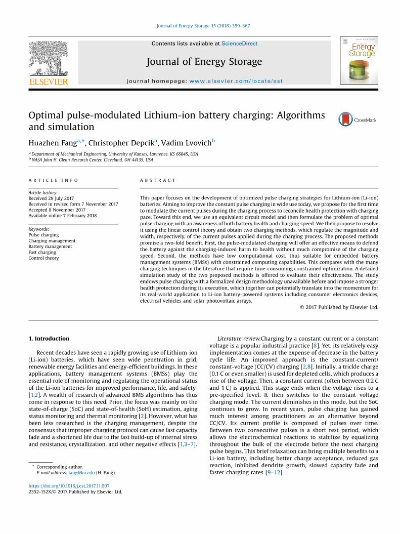
Fig. 1. RC-based equivalent circuit model for battery charging.
360 H. Fang et al. / Journal of Energy Storage 15 (2018) 359–367
It is observed that these battery charging practices areinadequate for two reasons. First, they are empirical, with littleknowledge available as to implementing them in the mostoptimal manner. For instance, determination of charge regimesfor CC and CV modes, despite its importance for the performanceof the CC/CV charging, has been mostly dependent on experience[13]. Second, they often operate as an open loop, simply takingenergy from the power supply and failing to take into account thebattery's history and current condition. These deficiencies limitthe opportunity for maximum health protection during charging.To remedy them, a promising solution is to deploy the feedbackcontrol, which introduces a controller and closes the loopbetween the controller and battery. As such, the chargingdynamics can be exploited, and the battery's charging profileoptimized to enhance the charging process. In this area, optimalcontrol in conjunction with electrochemical or equivalent circuitmodels has shown promise for optimizing charging protocols[14,3,15–17]. Model predictive control (MPC), which is alsooptimization-driven, represents another important class ofmethods with considerable interest because of its capability tohandle health-relevant input, state, and temperature constraints.A few studies have been devoted to MPC-based charging indiverse settings [18–20]. In addition, adaptive control isinvestigated in [21] to craft an energy-efficient fast chargingscheme, and sinusoidal charging studied in [22], which appliessinusoidal currents of the frequency minimizing the batteryimpedance. Optimal control design of charging/discharging of abattery during its operation is studied in [23] in order tomaximize the work it can perform over a given duration whilemaintaining a desired final energy level.
Statement of contributions. The primary contribution of this worklies in the investigation of optimal pulse-modulated charging. Inspite of recent advances as surveyed above, control-theory-enabledcharging management is still at a nascent stage, requiring moreeffort in this direction. Among the various open problems, aprominent one is concerned with pulse charging. Although it hasgained considerable popularity, there has been no systematictheoretical study about optimal design for pulse width andmagnitude modulation to improve charging performance. To fillthis gap, we leverage the linear control theory to develop optimalpulse charging solutions capable of balancing battery healthprotection and charging speed. Two methods will be obtained:the first one, named PAM-C, performs optimal pulse amplitudemodulation (PAM) throughout the charging process, and thesecond, named PWM-C, optimally modulates the pulse width. Inaddition to the benefit of enhanced health protection, the proposedmethods have a concise formulation and computational efficiency,suitable for real-time embedded BMS platforms. This work is thefirst one we are aware of that formalizes and optimizes the pulsecharging design, with a potential for transforming its practical use ina wide range of battery systems. It will also provide furtherincentives for the advancement of battery charging technology.
Organization. The rest of the paper is organized as follows.Section 2 introduces an equivalent circuit model oriented towardcharging dynamics. Based on this model, optimal pulse chargingstrategies will be developed and discussed subsequently inSection 3. To demonstrate effectiveness of the design, numericalresults are then presented in Section 4. Finally, concluding remarksare gathered in Section 5.
2. Resistance-capacitance model for charging
Throughout the paper, we consider a second-order resistance-capacitance (RC) model proposed by SAFT Batteries, Inc. for high-power Li-ion batteries [24,25]. As shown in Fig. 1, it consists of twocapacitors and three resistors. The resistor Ro represents the
electrolytic resistance within a battery cell. The double RC circuitsin parallel can simulate the migration of the electric charge duringthe charging (or discharging) processes. Specifically, the Rs�Cs
circuit accounts for the electrode surface region, which is exposedto the electrode-electrolyte interface; the Rb�Cb circuit representsthe bulk inner part of the electrode. Seeing a fast-speed transfer ofthe electric charge, the electrode surface is responsible for thehigh-frequency behavior during the charging processes andassociated with the immediate amount of charge that the batterycan absorb. However, it has a rather limited storage capacity. Bycontrast, the bulk electrode is where the majority of the electriccharge is stored in chemical form. Since the diffusion of ions withinthe electrode proceeds at a relatively slower speed, the Rb�Cb
circuit makes up the low-frequency part of the charging response.This implies that Rb > Rs and Cb � Cs. While inductance can bepresent in a lithium-ion battery circuit, it manifests itself only atcharging frequencies larger than 1 kHz [26], which indeed is faroutside of the effecting frequency of the pulse charging mecha-nisms to be presented in this paper. This makes it unnecessary toinclude an inductive element in this model.
Let Qb and Qs be the charge stored by Cb and Cs, respectively,and define them as the system state x. That is,
xðtÞ ¼ Q>b ðtÞ Q>
s ðtÞ� �>
. The state-space representation of the modelis then given by
xðtÞ ¼ AxðtÞ þ BuðtÞ; yðtÞ ¼ CxðtÞ þ DuðtÞ; ð1Þwhere uðtÞ is the charging current, yðtÞ the terminal voltage, and
A ¼� 1CbðRb þ RsÞ
1CsðRb þ RsÞ
1CbðRb þ RsÞ � 1
CsðRb þ RsÞ
2664
3775; B ¼
Rs
Rb þ RsRb
Rb þ Rs
2664
3775;
C ¼ Rs
CbðRb þ RsÞRb
CsðRb þ RsÞ� �
; D ¼ Ro þ RbRs
Rb þ Rs:
Note that uðtÞ > 0 for charging, uðtÞ < 0 for discharging, anduðtÞ ¼ 0 for idling. Derivation of (1) is based on the Kirchhoff'scircuit laws and capacitor equation, please see [24] for details. Itcan be easily verified that this system is controllable, indicating thefeasibility of steering the battery's state xðtÞ to any practicallypossible point.
The above RC model is linear and straightforward, but it cansatisfy the needs in many applications. This is because Li-ion batterysystems, e.g., those in electric vehicles, need to limit the minimumand maximum SoC during operation [27,28] for the purposes ofsafety, life, and a consistent power capability. Within this SoCwindow, the battery behavior can be approximated as linear.Furthermore, one can draw a linkage between this model and thewell-known single particle model (SPM) [29] — the charge transportintheRC modelisanalogoustothediffusionof ions withinasphericalparticle representing an electrode. This plain observation can befurther expanded to the approximate equivalence between themodel in Eq. (1) and the SPM, which is proven in [17].
H. Fang et al. / Journal of Energy Storage 15 (2018) 359–367 361
For health considerations, we need to constrain the differencebetween Vb and Vs throughout a charging process. The potentialdifference ~V ¼ Vs � Vb, arising when the charging begins, is tiedwith health detriment. The larger it is, the more potential harmcharging will bring. This conclusion is due to the resemblance that~V bears to the gradient of the concentration of ions within anelectrode. According to [17], there is an approximate mathematicalequivalence between the RC model and the SPM, and the potentialdifference ~V approximates the Li-ion concentration gradient in theSPM. Created during charging, the concentration gradient drivesthe diffusion of ions. However, too large a gradient value will causeinternal stress build-up, heating, solid-electrolyte interphase (SEI)formation, and other negative side effects [30–32]. An elaborativeinvestigation is offered in [33] that studies how the gradient in Li-ion concentration affects the Li-ion insertion process andconsequently, the internal stress and crack growth. Mechanicaldegradation in the electrode and capacity fade can happen oraccelerate when the magnitude of the gradient is too large. Thus,the uneven ion concentration should be suppressed duringcharging. In addition, this restriction should be implementedmore strictly as the SoC increases, when the battery becomes morevulnerable to the adverse effects caused by a large concentrationdifference [33].
It has been noticed that the pulse charging was indeed intendedto mitigate the build-up of the concentration gradient [34,35]because the short rest period of a pulse cycle will allow for the ionsto diffuse and distribute more evenly throughout the batteryelectrodes. In this work, we seek to maximize the potential of this“pulse-enhanced healthy charging” notion, through the design ofoptimal pulse modulation. Based on the above RC model, we willdevelop pulse-modulated charging methods, which can sendenergy into a battery in a health-aware manner but withoutsignificant compromise of the charging speed.
3. Optimal pulse charging
Despite the popularity of pulse charging, there have been scarcestudies about how to regulate the pulse charging process to extractthe full potential of this method. In this section, we will adopt acontrol-theoretic approach to bridge this divide and develop twomethods, named PAM-C and PWM-C, which adjust the pulseamplitude and width, respectively, during the charging operationfor the optimal performance.
Consider the current pulse signal u(t) shown in Fig. 2. It has aperiod of T, an active duration of w 2 ð0; T�, and a magnitude ofM > 0 during the active cycle; e.g.,(uðkT þ sÞ ¼ M; for s 2 ½0; wÞ;uðkT þ sÞ ¼ 0; for s 2 ½w; TÞ; ð2Þ
where k is a non-negative integer denoting the time index, and s anintermediate time variable. Modulation of the pulse refers to
Fig. 2. Pulse signal for charging.
adjustment of the two variables w and M. Suppose that the pulse isapplied to the model in Eq. (1) when t ¼ kT. Then, according to[36], the state response during ½kT; ðk þ 1ÞTÞ is given by(xðkT þ sÞ ¼ eAsxðkTÞ þ R s0 eAtdtBM; for s 2 ½0; wÞ;xðkT þ sÞ ¼ eAðs�wÞxðkT þ wÞ; for s 2 ½w; TÞ; ð3Þ
where t is an intermediate integral variable. It is noted that Eq. (3)depicts a state evolution that consists of two stages. In the firststage, for t 2 ½kT; kT þ wÞ, both elements of xðtÞ will increase drivenby the pulse current; whereas, the potential difference between Cb
and Cs will grow accordingly, which can be expressed by
V�ðtÞ ¼ VsðtÞ � VbðtÞ ¼ ExðtÞ;
with E ¼ � 1Cb
1Cs
h i. Under zero input in the second stage, the charge
will migrate from Cs to Cb driven by ~VðtÞ, and meanwhile, ~VðtÞ willbe in gradual decline. From the electrochemical perspective, thismirrors the equalization of electrochemical reactions across theelectrode, allowing for a catch-up with the transmittance ofelectric energy. The result will be mitigation of detrimental effectsand build-up of the potential difference.
At time t ¼ kT, the following cost function to minimize foroptimal pulse charging is defined:
Jðw; M; kTÞ ¼ a� R ðkþ1ÞT
kT~VðtÞdt
�2þ b
w2M2
¼ a� R ðkþ1ÞT
kT ExðtÞdt�2
þ b
w2M2 ;
ð4Þ
where a and b are scalar weight coefficients with a; b > 0. The firstterm of J, weighted by a, is based on the cumulative potentialdifference during ½kT; ðk þ 1ÞTÞ, which should be constrained forbattery health. Thus, it can be referred to as the health cost. Thesecond term, weighted by b, monotonically decreases with wM,the amount of charge delivered into the battery during this period.This impliesthat it isacostassociatedwiththe“chargingsluggishness”indeed. We can see that minimizing J will simultaneously penalizethe health and sluggishness costs, which will finally result in atrade-off between health protection and charging speed. This isaligned with our design goal of enabling pulse charging with anawareness of both health degradation and charging speed.
The selection of a and b is important for the generation of thecharging profile. According to the expression of J, one can find thatthe minimization will only rely on the ratio between a and b, i.e.,a=b, rather than their individual quantities. Thus, we can fix one ofthem and adjust the other one in practical weight selection. Duringthe adjustment, it should be kept in mind that the larger the ratio,the stronger the health protection, and the milder the currentprofile. This is because a and b symbolize the respectiveimportance of health and charging rate. To see this, one canconsider the extreme cases. If a=b ¼ 0, the maximum wM will besought to minimize J. Thus, this scenario will see zero emphasis onhealth protection and the most aggressive charging behavior. Ifa=b ! 1, the minimization then will be only about the healthcost, without any regard to the charging speed. The resultantminimizing solution will turn out to be zero current or no charging.In addition, we should also let a=b � 1 in the practicalimplementation. This is intended to offset the difference of thea-weighted term and b-weighted term in the order of magnitude—� R ðkþ1ÞT
kT~VðtÞdt
�2typically coming at 10�3–10�4 and 1=ðwMÞ2 at
10�2–100. If letting a=b � 1 instead of a=b � 1, the minimizationof J will be more prone to penalizing the charging sluggishness,thus yielding too large a charging rate. A further discussion of howto select a and b is summarized in Remark 3.
362 H. Fang et al. / Journal of Energy Storage 15 (2018) 359–367
With the formulation of Eq. (4), the next question is to find wand M that can minimize J. To this end, we should expressJðw; M; kTÞ in explicit terms of w and M.
By the Cayley–Hamilton theorem [36], we can obtain
eAs ¼ I þ 1 � e�ðpþqÞs
p þ qA;
where
p ¼ 1CbðRb þ RsÞ ; q ¼ 1
CsðRb þ RsÞ :
It then follows from Eq. (3) that the state evolution during½kT; kT þ wÞ is governed by
xðkT þ sÞ ¼ I þ 1 � e�ðpþqÞs
p þ qA
� �xðkTÞ
þ sB þ sp þ q
AB þ e�ðpþqÞs � 1
ðp þ qÞ2AB
" #M; ð5Þ
for s 2 ½0; wÞ. During ½kT þ w; ðk þ 1ÞTÞ,xðkT þ sÞ ¼ eAðs�wÞxðkT þ wÞ
¼ eAðs�wÞ�eAwxðkTÞ þ Rw0 eAtdtBM
�¼ eAs
�xðkTÞ þ Rw0 eAðt�wÞdtBM
�¼ eAs
�xðkTÞ þ Rw0 e�AtdtBM
�¼ I þ 1 � e�ðpþqÞs
p þ qA
� xðkTÞ þ wI þ w
p þ qA � eðpþqÞw � 1
ðp þ qÞ2A
!BM
" #:
ð6ÞDefine the integration of the potential difference ExðtÞ over
½kT; ðk þ 1ÞTÞ as
zðw; M; kTÞ ¼Z ðkþ1ÞT
kTExðtÞdt: ð7Þ
It can be written as the summation of two componentscorresponding to the active and rest periods of a pulse cycle:
zðw; M; kTÞ ¼ z1ðw; M; kTÞ þ z2ðw; M; kTÞ;where
z1ðw; M; kTÞ ¼ R kTþwkT ExðtÞdt;
z2ðw; M; kTÞ ¼ R ðkþ1ÞTkTþw ExðtÞdt:
Using Eqs. (5) and (6), it is obtained that
z1ðw; M; kTÞ ¼ Rw0 ExðkT þ sÞds
¼ wE þ wp þ q
EA þ e�ðpþqÞw � 1
ðp þ qÞ2EA
" #xðkTÞ
þ w2
2EB þ w2
2ðp þ qÞEAB � w
ðp þ qÞ2EAB � e�ðpþqÞw � 1
ðp þ qÞ3EAB
" #M;
ð8Þ
z2 w; M; kTð Þ ¼ R Tw EeAðs�wÞx kT þ wð Þds
¼ ðT � wÞE þ ðT � wÞp þ q
EA þ e�ðpþqÞT � e�ðpþqÞw
ðp þ qÞ2EA
" #xðkTÞ
þ Tw � w2 �
EB þ Tw � w2
p þ qEAB � ðe�ðpþqÞðT�wÞ � 1Þðe�ðpþqÞw � 1Þ
ðp þ qÞ3EAB
" #M:
ð9Þ
The relationship A2 ¼ �ðp þ qÞA is used in the above derivation ofz2. Inserting Eqs. (8)–(9) into Eq. (7) yields
zðw; M; kTÞ ¼ AxðkTÞ þ hðwÞM; ð10Þwhere
A ¼ TE þ Tp þ q
EA þ e�ðpþqÞT � 1
ðp þ qÞ2EA;
hðwÞ ¼ Tw �w2
2
� EB þ
Tw �w2
2ðp þ qÞ EAB � w
ðp þ qÞ2EAB � e�ðpþqÞT � e�ðpþqÞðT�wÞ
ðp þ qÞ3EAB:
Hence, Jðw; M; kTÞ in Eq. (4) can be rewritten as
J w; M; kTð Þ ¼ a½AxðkTÞ þ hðwÞM�2 þ b
w2M2: ð11Þ
Even though the expression of Jðw; M; kTÞ is simplified as inEq. (12), minimizing it with respect to w and M simultaneously isintractable. The first reason is the non-linearity involved, and whatmakes the matter worse is the non-convexity of J over the domaindefined by w and M. However, J is convex with respect to w forw 2 ½0; T� and also convex with respect to M for M 2 ½0; 1Þ. Theconvexity results from the fact that, within the specified interval ofw or M, the two terms of J are both convex. Hence, this implies thefeasibility of fixing either w or M and conducting the optimizationwith respect to the other one, leading us to some viable solutions.The following two outcomes will be produced.
Pulse-amplitude-modulated charging (PAM-C). If we fix w,the pulse amplitude to apply at time kT can be determined readily.In this case, J will be convex with respect to M for M 2 ð0; 1Þ. Thus,to find the minimizing M, we can let @J=@M ¼ 0, which then givesthe following quartic equation:
aw2h2ðwÞM4 þ aAxðkTÞw2hðwÞM3 � b ¼ 0: ð12ÞThe properties of quartic equations have been well studied anddocumented in the literature, e.g., [37,38]. Based on the existingresults, it can be determined that Eq. (13) has four roots, two realones and two complex conjugate ones. Of the two real roots, one ispositive and the other negative, and the positive root is the onlymeaningful solution for the considered problem since chargingimplies M > 0. The quartic equation can be analytically andefficiently solved using different methods [37,38], implyingconvenience for the execution of charging control.
It should be noted that the obtained M can be aggressive,especially in the beginning of the charging process, which mayincur certain damaging effects. This motivates us to integratebounded control with the practice of the pulse charging. That is, anupper bound, Mmax, for the charging current is pre-specified, andM ¼ Mmax enforced if the solution derived from solving (13) islarger than Mmax. Adding further protection against over aggressivecharging, this effort will eliminate the risk imposed to the battery.
Pulse-width-modulated charging (PWM-C). Now, consider afixed M and regulating the pulse width w. We notice thatminimizing Jðw; M; kTÞ over w can be viewed as a nonlinear leastsquares problem, which can be addressed by the numerical Gauss-Newton algorithm. Define
rðwÞ ¼ffiffiffiffia
p ½AxðkTÞ þ hðwÞM�ffiffiffiffib
pwM
24
35:
The derivative of rðwÞ with respect to w is
rwrðwÞ ¼ffiffiffiffia
p rwhðwÞM�
ffiffiffiffib
pw2M
24
35
H. Fang et al. / Journal of Energy Storage 15 (2018) 359–367 363
The Gauss–Newton proceeds by the following iteration procedure[39]
wð‘þ1Þ ¼ wð‘Þ � r r>wr wð‘Þ� �
rwr wð‘Þ� �h i�1�r>
wr wð‘Þ� �
r wð‘Þ� �
; ð13Þ
where ‘ is the iteration number and r 2 ð0; 1Þ the step size. It canbe initialized by wð0Þ ¼ d for d 2 (0, T]. On satisfaction of the stopcondition, the iteration terminates, and the obtained wð‘Þ will beassigned to wðkTÞ as the width of the pulse to execute at time kT.Note that if the wð‘Þ acquired in the final iteration is larger than T,then let wðkTÞ ¼ T, which indicates that the battery status cantolerate full-duty-cycle pulse (continuous) charging in this stage. Itis known that the Gauss-Newton algorithm can have a quadraticrate of convergence, so Eq. (13) can hopefully converge in severaliterations. In addition, it is practically easy for one to choose aneducated initial point for w since it lies in the interval ½0; T�, whichwill speed up the convergence substantially.
The PAM-C and PWM-C methods offer two ways to performpulse-modulated charging. A discussion of them is as follows.
Remark 1. Difference from the literature
This works differs from the methods in the literature in severalaspects. First, this is the first work to our knowledge that isconcerned with control-theory-based pulse charging design,which can help overcome empiricism in the practice of pulsecharging. Second, the charging control design is based on anequivalent circuit model rather than electrochemical models oftenin the literature on charging control. Both models have their ownadvantages. But the mathematical conciseness of an ECM is key forcomputational efficiency. Form this viewpoint, the PAM-C andPWM-C methods are advantageous for deployment and use inresource-constrained computing platforms, such as real-timeembedded BMSs. Finally, the primary health consideration inthe proposed design is concerned with constraining potentialdifference, which is an approximation of the Li-ion concentrationgradient. This is the first attempt in charging control design to ourknowledge.
Remark 2. Computational efficiency
Eqs. (12) and (13) can be implemented efficiently from acomputational point of view. This is advantageous to thedeployment and use of the PAM-C and PWM-C methods especiallyin resource-constrained computing platforms, such as real-timeembedded BMSs, in comparison to constrained-optimization-based charging techniques; e.g., [3,14–16].
Remark 3. Practical application of PAM-C and PWM-C
To transition the PAM-C and PWM-C algorithms to practice, onefirst needs to identify the model parameters in order to obtain anaccurate model. Parameter identification of the considered RCmodel has been investigated in [40], in which the identifiability isanalyzed and a real-time parameter estimation algorithm devel-oped with proven convergence. In addition, real-time stateestimation will be necessary. The design of the PAM-C and PWM-
C methods is premised on state feedback, which assumes that thestate vector x(kT) is known for each k. However, x(kT) as theinternal state of the battery is not directly measurable. To addressthis issue, we can replace x(kT) with its estimate x̂ðkTÞ acquiredfrom the input and output measurements. This can be accom-plished by the celebrated Kalman filter on account of its optimalityand relatively easy execution. The application of the Kalman filterto battery estimation has been investigated prior in the literature,e.g., [41–44]. Realization of the PAM-C and PWM-C algorithms will
need the development of power electronics devices, especially acontrollable current source, which will require continued research.
Remark 4. Choice of a and b
When the weight coefficients a and b take different values, thecharging profiles will change accordingly, highlighting the impor-tance of finding appropriate a of b for the implementation ofPAM-C and PWM-C. A basic guideline is as follows:
� a � b, because the a-weighted term in J is an order ofmagnitude smaller than the b-weighted term.
� One can fix one of a and b and adjust the other parameter, as aresult of the minimization of J relying only on the ratio betweena and b as is evident from the expression of J and Eqs. (12) and(13). A convenient means is to adjust a with b ¼ 1.
� The ratio a=b should increase gradually through the chargingprocess to constrain the charging rate more strictly when the SoCgrows, because of a battery's susceptibility increasing with SoCto the charging current.
� A larger a=b implies a stronger health protection and a lessaggressive charging profile.
Remark 5. Extension to other models
The methodology developed in this work can be extended toother battery models. As an example, an extension to the SPM canbe achieved by reducing the PDE equations to the linear state-space representation, formulating an optimization problem, andthen solving by finding the best pulse width and/or amplitude. It isworth pointing out that extensions can be made to accommodatetemperature dynamics as a means to suppress the charging-induced heat build-up. Specifically for the considered model inEq. (1), a thermal coupling can be performed as shown in [40]. Wecan then follow similar lines to accomplish the pulse-modulatedcharging design based on the modified model.
4. Illustrative examples
In this section, we present two numerical examples todemonstrate the application of the proposed PAM-C and PWM-C
methods. The following simulation setting is used:
� We consider a Lithium-ion battery described by the RC model inFig. 1 with known parameters: Cb ¼ 82kF,Rb ¼ 1:1 mV,Cs ¼ 4:074 kF, Rs ¼ 0:4 mV, and Ro ¼ 1:2 mV [24].
� The battery has a nominal capacity of 8 Ah, with the operatingvoltage ranging from 3.50 V to 3.85 V.
� The SoC before charging is 30% at the voltage of 3.605 V, and thecut-off voltage is 3.85 V.
� For PAM-C, two sets of parameters are used for evaluation and
comparison: (1) a ¼ 2 � 203�SoCþ1 and b ¼ 1, and (2) a ¼ 2 �204�SoCþ1 and b ¼ 1. For PWM-C, two parameter sets are also
selected: (1) a ¼ 203�SoCþ1 and b ¼ 1, and (2) a ¼ 2 � 203�SoCþ1
and b ¼ 1. Here, they are selected according to the guidelineoffered in Remark 3 and through an empirical adjustment. Notethat the a increasing with the SoC is meant to enable a healthcost commensurate with the charge transferred into the battery,which will ensure sufficient health protection under a large SoC.
� The period T of the pulses is 0.5 s. The active duration w is set tobe 0.4 s for PAM-C and varies with the charging status for PWM-C.
� The pulse magnitude is dynamically regulated for PAM-C asgoverned by the algorithm, yet upper bounded by Mmax ¼ 8 A,equivalent to 1 C, to avoid over aggressive charging; for PWM-C, it
364 H. Fang et al. / Journal of Energy Storage 15 (2018) 359–367
is fixed at 8 A. Note that the magnitude is recommended to be nomore than 1 C in practice.
Example 1: Evaluation of PAM-C and PWM-C. The PAM-Cmethod is executed under the setting defined above anddemonstrated in Fig. 3. The left column of Fig. 3 sums up theresults for the first a�b set, and the right column for the secondset. The figures in both columns show similar trends but differentnumerical values. Let us take a look at the left column first. Asshown in Fig. 3a, pulses of 8 A are applied at the initial stage ofcharging. This is because the the battery can allow for a largecharging current when at a low SoC level but PAM-C is subjected tothe pre-set bound Mmax ¼ 8 A. After about half an hour, the pulsemagnitude will decrease as the SoC grows over time. Weakercurrent pulses can bring less harm to the internal health of thebattery after it has stored a significant amount of electric energy.
Fig. 3. Simulation of charging by PAM-C in Example 1. The left column is for the parametb ¼ 1. (a-b) The PAM-C-generated charging current profile; (c-d) the resultant potetime.
The potential difference Vs � Vb , quantifying the charging-inducedeffect on health, is illustrated in Fig. 3c. Without surprise, it is keptat a stable level during the initial stage, due to the fixed pulsemagnitude. Then, a steadily declining trend is seen, and the voltagedifference at the termination of charging is remarkably lower thanthat at the initial stage. A magnified view further reveals a rise-drop pattern that repeats itself — the potential difference risesduring the active charging duration and drops during the restperiod in each pulse cycle. This prevents the build-up of thepotential difference and helps mitigate damaging effects. Thetrajectory of the SoC is given in Fig. 3e. The charging process lastsabout 1 hr before it ends, with the SoC reaching 97.48%. It is seenthat the growth rate of the SoC gradually reduces, which is causedby the diminishing pulse magnitude in Fig. 3a. Now, consider thePAM-C method applied with the second a�b set and the figures onthe right column. It is seen from Fig. 3b that the charging
er set a ¼ 2 � 203�SoCþ1 and b ¼ 1, and the right column for a ¼ 2 � 204�SoCþ1 andntial difference through time; (e-f) the resultant trajectory of the SoC through
H. Fang et al. / Journal of Energy Storage 15 (2018) 359–367 365
aggressiveness in this case is suppressed more strictly, with theamplitude beginning to decline after only 0.3 h. This is caused bythe appreciably larger ratio between a and b. The charging processas a result is increased to 1.5 h from 1 h in Fig. 3a. Meanwhile, thepotential difference reduces to a lower level overall, as is shown inFig. 3d, which implies potentially better health. Another benefit isthat the SoC achieves 98.77% at the end of charging, about 1.31%higher than that shown in Fig. 3e. This shows that more energy canbe put into a battery when the charging current is smaller.
The simulation of the PWM-C method using two parameter setsis given in Fig. 4. Let us begin with the left column for the first a�bset. From Fig. 4a, a constant current composed of full-duty-cyclepulses is applied in the first 0.2 h. That means the optimal w in thiscase is equal to T, which is possible because of the battery's abilityto accommodate a high charging rate at a low-SoC level. This isfollowed by current pulses with decreasing widths, as illustrated in
Fig. 4. Simulation of charging by PWM-C in Example 1. The left column is for the parameand b ¼ 1. (a) and (b) The PWM-C-generated charging current profile; (c) and (trajectory of the SoC through time.
the magnified view. Resembling the downward trend of themagnitude in Fig. 3a, the decline of the pulse width is to reduce therisk of harm to the battery's health. The charging profile hereshares certain similarity with the one used in [6], whichexperimentally verifies charging with a constant current firstand then a series of pulses. The potential difference is shown inFig. 4c. It remains almost constant at the beginning but decreaseswith the progress of charging, with the rise-drop pattern appearingin each pulse cycle. In Fig. 4e, the SoC rises and ends at 95.87%when the charging is terminated after 1 h upon the reach of thecut-off voltage. In the meantime, a decelerated SoC growth isobserved, similar to Fig. 3e and meant to reduce the harm to thebattery at high SoC. The right column presents figures for thesecond set of a and b. Fig. 3b illustrates that the increased ratio ofa=b “abates” the charging process, with the active periods of thepulses reducing faster after the charging begins. According to
ter set (1) a ¼ 2 � 203�SoCþ1 and b ¼ 1, and the right column for a ¼ 2 � 203�SoCþ1
d) the resultant potential difference through time; (e) and (f) the resultant
366 H. Fang et al. / Journal of Energy Storage 15 (2018) 359–367
Fig. 4d and f, the potential difference level is more inhibited, andthe final SoC increases slightly to 95.98% after 1.17 h of charging.
Example 2: Comparison with constant-pulse charging. Thisexample assesses the PAM-C and PWM-C methods (each using itsfirst parameter set in Example 1) through a comparison with thetraditional constant-pulse charging (CPC). We assume the CPCmethod applies fixed periodic pulses. Their magnitude of 8 A, andthe period is 0.5 s with an active duration of 0.4 s. In the simulation,it takes CPC 0.81 hrs to finish charging, which is modestly fasterthan both PAM-C and PWM-C. Fig. 5a compares the SoC-voltageprofiles of PAM-C and CPC during the charging process. During theinitial phase, the voltage yielded by PAM-C with respect to SoC iskept at a higher level than CPC, due to its large pulse magnitude. As
Fig. 5. Comparison of PAM-C and PWM-C with constant pulse charging (CPC) inExample 2: (a) the SoC-voltage profiles of PAM-C and CPC; (b) the SoC-voltageprofiles of PWM-C and CPC; (c) the potential difference over time produced by CPC(compare with PAM-C in Fig. 3c and PWM-C in Fig. 4c).
the charging progresses, the PAM-C method reduces the magnitudegradually, and its potential difference ends up lower than that ofCPC. This helps PAM-C put more charge into a battery, which isverified by the fact that the terminal SoC is 97.48% for PAM-C incontrast to 95.12% for CPC. Fig. 5b offers an examination of thePWM-C case. It is found that PWM-C can also improve the chargeacceptance with the final SoC at 95.87%. Furthermore, Fig. 5c leadsus to understand the major advantage of the PAM-C and PWM-Cmethods — better battery health protection. With CPC, thepotential difference will be kept at higher than PAM-C and PWM-C for most of the charging process, especially in the latter part. Thiscan cause internal damage when the SoC is large, placing thebattery in potential jeopardy. Therefore, PAM-C and PWM-C
outperform CPC in terms of health awareness and protection.The above results are aligned with the anticipation that the
pulse magnitude/width modulation can reduce the potentialdifference during charging to reduce health degradation. Thesimulation also results in several questions for further inquiry.Among them, the determination of the weight coefficients a and bneeds more investigation as aforementioned. Another issue is theassessment and comparison of the PAM-C and PWM-C methods. Asto which one of them is better, there is no clear-cut answer nowbecause a few factors need to be taken into account, includingcharging speed, computational complexity, battery health, eco-nomic cost, and even user satisfaction. A plausible attempt toevaluate a charging approach will require a mix of theoretical andexperimental examination, which will be part of our future quest.
5. Conclusion
This paper studies the problem of optimal pulse modulation forbattery charging. We describe the charging dynamics using an RCmodel and consider the optimal regulation from a control-theoretic perspective. The design is built on minimizing a costfunction that accounts for health cost and charging speed. It leadsto two pulse charging methods, one based on pulse amplitudemodulation and the other on pulse width modulation. We presenta simulation-based examination of both methods that illustratesenhanced health protection and charge acceptance over priormethodologies. The results will not only benefit the real-worldapplication of pulse charging, but also provide incentives for futureresearch on control-theory-based charging and BMS design. Ourfuture work will include the comprehensive assessment of theproposed methods and the extension of the design to other batterymodels and electrochemistries.
References
[1] H. Bergveld, W. Kruijt, P. Notten, Battery Management Systems: Design byModeling, Springer, 2002.
[2] C.D. Rahn, C.-Y. Wang, Battery Systems Engineering, Wiley, 2013.[3] B. Suthar, V. Ramadesigan, S. De, R.D. Braatz, V.R. Subramanian, Optimal
[4] R. Spotnitz, Simulation of capacity fade in lithium-ion batteries, J. PowerSources 113 (2003) 72–80.
[5] M. Abdel Monem, K. Trad, N. Omar, O. Hegazy, B. Mantels, G. Mulder, P. Van denBossche, J. Van Mierlo, Lithium-ion batteries: evaluation study of differentcharging methodologies based on aging process, Appl. Energy 152 (2015) 143–155.
[6] D.S. Hyun, H.J. Hwang, D.-U. Kim, S. Hwang, Y.-H. Yun, B.S. Oh, Development ofan optimal charging algorithm of a Ni-MH battery for stationary fuel cell/battery hybrid system application, Int. J. Hydrogen Energy 38 (2013) 9008–9015.
[7] C. Wu, J. Chen, C. Xu, Z. Liu, Adaptive control strategy of a fuel cell/batteryhybrid power system, Proceedings of American Control Conference (2016)7492–7497.
[8] K. Young, C. Wang, L. Wang, K. Strunz, Electric vehicle battery technologies, in:R. Garcia-Valle, J.P. Lopes (Eds.), Electric Vehicle Integration into ModernPower Networks, Springer, 2012.
H. Fang et al. / Journal of Energy Storage 15 (2018) 359–367 367
[9] L.T. Lam, H. Ozgun, O.V. Lim, J.A. Hamilton, L.H. Vu, D.G. Vella, D.A.J. Rand,Pulsed-current charging of lead/acid batteries – a possible means forovercoming premature capacity loss? J. Power Sources 53 (1995) 215–228.
[10] B.K. Purushothaman, U. Landau, Rapid charging of lithium-ion batteries usingpulsed currents: a theoretical analysis, J. Electrochem. Soc. 153 (2006) A533–A542.
[11] A. Aryanfar, D. Brooks, B.V. Merinov, W.A. Goddard, A.J. Colussi, M.R. Hoffmann,Dynamics of lithium dendrite growth and inhibition: pulse chargingexperiments and Monte Carlo calculations, J. Phys. Chem. Lett. 5 (2014) 1721–1726.
[12] J. Li, E. Murphy, J. Winnick, P.A. Kohl, The effects of pulse charging on cyclingcharacteristics of commercial lithium-ion batteries, J. Power Sources 102(2001) 302–309.
[13] Y. Wong, W. Hurley, W. Wölfle, Charge regimes for valve-regulated lead-acidbatteries: performance overview inclusive of temperature compensation, J.Power Sources 183 (2008) 783–791.
[14] R. Klein, N. Chaturvedi, J. Christensen, J. Ahmed, R. Findeisen, A. Kojic, Optimalcharging strategies in lithium-ion battery, Proceedings of American ControlConference (2011) 382–387.
[15] J. Yan, G. Xu, H. Qian, Z. Song, Model predictive control-based fast charging forvehicular batteries, Energies (2011) 1178–1196.
[16] H. Perez, N. Shahmohammadhamedani, S. Moura, Enhanced performance ofLi-ion batteries via modified reference governors and electrochemical models,IEEE/ASME Trans. Mechatron. (2015).
[17] H. Fang, Y. Wang, J. Chen, Health-aware and user-involved battery chargingmanagement for electric vehicles: linear quadratic strategies, IEEE Trans.Control Syst. Technol. 25 (2017) 911–923.
[18] M. Torchio, N.A. Wolff, D.M. Raimondo, L. Magni, U. Krewer, R.B. Gopaluni, J.A.Paulson, R.D. Braatz, Real-time model predictive control for the optimalcharging of a lithium-ion battery, American Control Conference, (2015) , pp.4536–4541.
[19] J. Liu, G. Li, H.K. Fathy, An extended differential flatness approach for thehealth-conscious nonlinear model predictive control of lithium-ion batteries,IEEE Trans. Control Syst. Technol. 25 (2017) 1882–1889.
[20] J. Liu, G. Li, H.K. Fathy, A computationally efficient approach for optimizinglithium-ion battery charging, ASME J. Dyn. Syst. Meas. Control 138 (2015)021009-021009-8.
[21] R. Wai, S. Jhung, Design of energy-saving adaptive fast-charging controlstrategy for Li-Fe-PO4 battery module, IET Power Electron. 5 (2012) 1684–1693.
[22] L.R. Chen, S.L. Wu, D.T. Shieh, T.R. Chen, Sinusoidal-ripple-current chargingstrategy and optimal charging frequency study for li-ion batteries, IEEE Trans.Ind. Electron. 60 (2013) 88–97.
[23] T. Wang, C.G. Cassandras, Optimal control of batteries with fully and partiallyavailable rechargeability, Automatica 48 (2012) 1658–1666.
[24] V.H. Johnson, A.A. Pesaran, T. Sack, Temperature-dependent battery models forhigh-power lithium-ion batteries, Proceedings of 17th Electric VehicleSymposium (2000).
[25] V.H. Johnson, Battery performance models in ADVISOR, J. Power Sources 110(2002) 321–329.
[26] F.C. Laman, M.W. Matsen, J.A.R. Stiles, Inductive impedance of a spirally woundLi/MoS2 cell, J. Electrochem. Soc. 133 (1986) 2441–2446.
[27] D. Knutsen, O. Willén, A study of electric vehicle charging patterns and rangeanxiety, Technical Report, Uppsala University, 2013.
[28] T. Markel, A. Simpson, Plug-in hybrid electric vehicle energy storage systemdesign, Advanced Automotive Battery Conference (2006).
[29] S. Santhanagopalan, Q. Guo, P. Ramadass, R.E. White, Review of models forpredicting the cycling performance of lithium ion batteries, J. Power Sources156 (2006) 620–628.
[30] M.B. Pinsona, M.Z. Bazant, Theory of SEI formation in rechargeable batteries:capacity fade, accelerated aging and lifetime prediction, J. Electrochem. Soc.160 (2013) A243–A250.
[31] W.H. Woodford IV, Electrochemical shock: Mechanical degradation of ion-intercalation materials, Massachusetts Institute of Technology, 2013 (Ph.D.thesis).
[32] T.M. Bandhauera, S. Garimellaa, T.F. Fullerb, A critical review of thermal issuesin lithium-ion batteries, J. Electrochem. Soc. 158 (2011) R1–R25.
[33] M. Klinsmann, The Effects of Internal Stress and Lithium Transport on Fracturein Storage Materials in Lithium-Ion Batteries, Karlsruhe Institute ofTechnology, 2015 (Ph.D. thesis).
[34] R. Cope, Y. Podrazhansky, The art of battery charging, Proceedings of theFourteenth Annual Battery Conference on Applications and Advances (1999)233–235.
[35] R. Baroody, Evaluation of rapid electric battery charging techniques, Universityof Nevada, Las Vegas, 2009 (Master's thesis).
[36] C.-T. Chen, Linear System Theory and Design, 3rd ed., Oxford University Press,2012.
[37] S. Neumark, Solution of Cubic and Quartic Equations, Pergamon Press, 1965.[38] S.L. Shmakov, A universal method of solving quartic equations, Int. J. Pure Appl.
Math. 71 (2011) 251–259.[39] Å. Björck, Numerical Methods for Least Squares Problems, SIAM Press, 1996.[40] M. Sitterly, L.Y. Wang, G. Yin, C. Wang, Enhanced identification of battery
models for real-time battery management, IEEE Trans. Sustain. Energy 2 (2011)300–308.
[41] X. Zhao, R.A. de Callafon, Modeling of battery dynamics and hysteresis forpower delivery prediction and SOC estimation, Appl. Energy 180 (2016) 823–833.
[42] L. Zheng, L. Zhang, J. Zhu, G. Wang, J. Jiang, Co-estimation of state-of-charge,capacity and resistance for lithium-ion batteries based on a high-fidelityelectrochemical model, Appl. Energy 180 (2016) 424–434.
[43] G.L. Plett, Extended Kalman filtering for battery management systems of lipb-based HEV battery packs: part 3. State and parameter estimation, J. PowerSources 134 (2004) 277–292.
[44] X. Lin, A.G. Stefanopoulou, Y. Li, R.D. Anderson, State of charge imbalanceestimation for battery strings under reduced voltage sensing, IEEE Trans.Control Syst. Technol. 23 (2015) 1052–1062.