http://jim.sagepub.com/ Structures Journal of Intelligent Material Systems and http://jim.sagepub.com/content/early/2011/09/08/1045389X11420591 The online version of this article can be found at: DOI: 10.1177/1045389X11420591 published online 11 September 2011 Journal of Intelligent Material Systems and Structures Yijin Chen, Jian Sun, Yanju Liu and Jinsong Leng MC) Tube 2 Experiment and Analysis of Fluidic Flexible Matrix Composite (F Published by: http://www.sagepublications.com can be found at: Journal of Intelligent Material Systems and Structures Additional services and information for http://jim.sagepub.com/cgi/alerts Email Alerts: http://jim.sagepub.com/subscriptions Subscriptions: http://www.sagepub.com/journalsReprints.nav Reprints: http://www.sagepub.com/journalsPermissions.nav Permissions: What is This? - Sep 11, 2011 Proof >> at Harbin Inst. of Technology on November 28, 2011 jim.sagepub.com Downloaded from
Transcript
http://jim.sagepub.com/Structures
Journal of Intelligent Material Systems and
http://jim.sagepub.com/content/early/2011/09/08/1045389X11420591The online version of this article can be found at:
DOI: 10.1177/1045389X11420591
published online 11 September 2011Journal of Intelligent Material Systems and StructuresYijin Chen, Jian Sun, Yanju Liu and Jinsong Leng
MC) Tube2Experiment and Analysis of Fluidic Flexible Matrix Composite (F
Published by:
http://www.sagepublications.com
can be found at:Journal of Intelligent Material Systems and StructuresAdditional services and information for
Journal of Intelligent Material Systemsand StructuresXX(X) 1–12� The Author(s) 2011Reprints and permissions:sagepub.co.uk/journalsPermissions.navDOI: 10.1177/1045389X11420591jim.sagepub.com
Experiment and Analysis ofFluidic Flexible Matrix Composite(F2MC) Tube
Yijin Chen1, Jian Sun1, Yanju Liu2 and Jinsong Leng1
AbstractIn this research, a fluidic flexible matrix composites (F2MC) tube composed of flexible matrix composite (FMC) andinner liner is investigated. Significant changes in effective axial elastic modulus could be achieved through controlling theinterior fluid. Based on classical laminated-plate theory and anisotropic elasticity, a three-dimensional analytical methodis proposed to characterize the axial mechanical behavior of the F2MC tube. In comparison with the experiment result,the analysis is deemed to possess satisfying accuracy in the effective axial elastic modulus prediction of the F2MC tube. Inaddition, the effective axial elastic modulus ratio is discussed under different material and geometry parameters of thetube. The analysis result shows that the modulus ratio can reach up to 120 by refining the material and geometry para-meters. Therefore, the investigated F2MC tube could serve as potential candidate for the morphing skin applicationswith variable stiffness.
Traditionally, aircrafts are designed according to theirspecial mission, flight altitude, Mach number, and flightweight and usually optimized in the most concernedflight performance. However, in an integrated flight cyclewith continuously varied flight parameters, the geometryof wings is not always optimal. In view of these, morph-ing aircrafts are designed to solve this problem (Bubertet al., 2010; Thill et al., 2008), and the recently emergedsmart materials and their composites open an avenue tothe development of morphing aircrafts. Morphing air-crafts can realize the optimal objective through changingits aerodynamic layout according to the outside flightenvironment. One of the key techniques to realize morph-ing aircraft is the morphing skin (Bartley-Cho et al.,2004), which should endure enough deformation if signif-icant changes of chord length, span length, sweepbackangle, and wing area are accomplished by the aircraftwing, as well as possessing enough out-of-plane stiffnessto maintain the aerodynamics configuration during thedeformation process. Meanwhile, to reduce the energyconsumption of actuators, low in-plane stiffness is desiredduring the deformation process (Murray et al., 2010;Reich et al., 2007; Yin et al., 2008).
Currently, one of the main methods to realize thedeformation function of the morphing skin is achieved
by slide structures, such as traditional stiff skin of fishscales (Long et al., 1996). While this kind of materialcan meet the demand of aircraft wing on stress-bearingcapability and deformation, it cannot meet the demandof smooth surface and entire air tightness and subse-quently cause the poor aerodynamic efficiency of themorphing wing. Another method to realize the functionis achieved by the material itself, such as rubbery mate-rials with higher flexibility and elasticity (Andersenet al., 2007). Even though this kind of skin can satisfythe requirement of deformation and air tightness, theentire stress-bearing capability of the aircraft wing isdecreased because of low stiffness and stretch of thematerial. Another type of material applied in this realmis shape-memory polymers (SMPs; Perkins et al., 2004;Yin et al., 2008), which exhibit a large deformationcapability when its elastics modulus is low at high
1Centre for Composite Materials, Science Park of Harbin Institute of
Technology, Harbin, P.R. China2Department of Aerospace Science and Mechanics, Harbin Institute of
Technology, Harbin, P.R. China
Corresponding author:
Jinsong Leng, Centre for Composite Materials, No. 2 YiKuang Street,
Science Park of Harbin Institute of Technology, Harbin, P.O. Box 3011,
temperature. But the limited stress-bearing capabilityand difficult control of heating temperature hindertheir further applications.
Recently, a new kind of variable stiffness skin wasproposed to solve these problems (Philen et al., 2006,2007). The skin is integrated by flexible matrix andvariable stiffness tube. While the variable stiffness skinexhibits high out-of-plane stiffness, it can undergo largestrain and has low in-plane stiffness. One of the keycomponents is the variable stiffness tube, namely, flui-dic flexible matrix composites (F2MC) tube. The F2MCtube was first proposed by Shan et al. (Philen et al.,2006; Shan et al., 2007), and it would experience a largeaxial stiffness increase when the valves are closed.Utilizing elasticity solution of homogenous isotropiccylinder and Lekhnitskii’s elasticity solution for ahomogenous orthotropic cylinder, they also developeda three-dimensional (3D) analytical model (Shan et al.,2009) to characterize the axial stiffness behavior of asingle F2MC tube. The model prediction shows a goodagreement with the experiment result. And based onthis model, they briefly analyze the influence of bulkmodulus of fluid, elastic modulus, and thickness ofinner liner to the axial effective stiffness. In this regard,by applying classical laminated-plate theory and three-dimensional (3D) anisotropic elasticity (Bakaiyan et al.,2009; Xia et al., 2001a, b), a different 3D analyticalmethod is proposed in this study to characterize theaxial stiffness behavior of a single F2MC tube. Thederivation process of the elasticity solution theory is rel-atively simple. In addition, the influencing factors offiber volume fraction of the outer flexible matrix com-posite (FMC) tube, Poisson’s ratio of inner liner, thick-ness of fluid, and outer FMC tube are taken intoaccount to determine the change of axial effective stiff-ness of the investigated tube. The analysis results couldprovide relatively comprehensive references for designand fabrication of the F2MC tube.
Analysis Procedure
Model of the F2MC Tube
The F2MC tube is manufactured by filament-woundFMC laminate for the outer tube and rubber materialfor the inner liner (Shan et al., 2007). The outer mate-rial of the F2MC tube is considered to be homogenousorthotropic, which has an opposite fiber orientation(6f) with respect to the axial direction of the rube.The outer FMC laminate is perfectly bonded to theinner liner and forms the F2MC tube as shown inFigure 1. Through controlling the fluid inside the innerliner by valve, axial stiffness of the F2MC tube willvary over a large interval. The entire F2MC tube is uni-formly stretched to a strain of e0 with an applied loadof Fex. As a result, a pressure of P is developed in theenclosed fluid.
Stress and Strain Analysis of the F2MC Tube
Consider the F2MC cylindrical tube subjected to aninternal pressure load and an axial load as shown inFigure 2. The cylindrical coordinate system is con-structed for a convenient analysis, and the coordinatesare denoted by r as the radial, u as the hoop, and z asthe axial coordinates of the cylinder. When tubes aresubjected to axisymmetric load, the stress and strainare independent of u. With the assumption mentionedpreviously, the displacement field can be expressed as(Xia et al., 2001a)
ur = ur(r), uu = uu(r, z), uz = uz(z) ð1Þ
where ur, uu, and uz are radial, hoop, and axial displace-ments, respectively.
For the anisotropic materials, the stress and straintransformation of the kth layer from material coordi-nate to cylindrical coordinate is given by
sz
su
sr
tur
tzr
tzu
8>>>>>><>>>>>>:
9>>>>>>=>>>>>>;
(k)
=
C11 C12 C13 0 0 C16
C12 C22 C23 0 0 C26
C13 C23 C33 0 0 C36
0 0 0 C44 C45 0
0 0 0 C45 C55 0
C16 C26 C36 0 0 C66
26666664
37777775
(k) ez
eu
er
gur
gzr
gzu
8>>>>>><>>>>>>:
9>>>>>>=>>>>>>;
(k)
ð2Þ
Considering the axisymmetric properties of the sys-tem and Equation (1), the strain–displacement expres-sions are simplified as
Figure 1. Illustration of the F2MC tube.
Figure 2. The F2MC tube in cylindrical coordinate system.
2 Journal of Intelligent Material Systems and Structures XX(X)
at Harbin Inst. of Technology on November 28, 2011jim.sagepub.comDownloaded from
The expressions of the equilibrium equations aresimplified as follows:
ds(k)r
dr+
s(k)r � s(k)
u
r= 0 ð5Þ
dt(k)ur
dr+
2t(k)ur
r= 0 ð6Þ
dt(k)zr
dr+
t(k)zr
r= 0 ð7Þ
The solution of Equations (6) and (7) can be given asfollows:
s(k)ur =
A(k)
r2, s(k)
zr =B(k)
r2ð8Þ
According to Xia’s elasticity solution for a homoge-nous cylinder under an internal pressure load and anaxial load, the expression of displacement field can beobtained under the following two conditions (Xia et al.,2001a, b):
1. If b(k) 6¼ 0, which is anisotropic,
u(k)r = D(k)rb(k)
+ E(k)r�b(k)
+a(k)
1 e0r
1� (b(k))2
+ a(k)2 g0r2 ð9Þ
2. If b(k) = 0, which is isotropic or isotropic in (r � u)plane,
of all layers, g0 is the twist of tube per unit length, and
D(k) and E(k) are unknown constants of integration
determined from the boundary conditions.
Laminated-Plate Properties
The off-axis stiffness constants in matrix C(k)
ij
h ican be
obtained from the on-axis coordinate constants inmatrix C(k)
ij
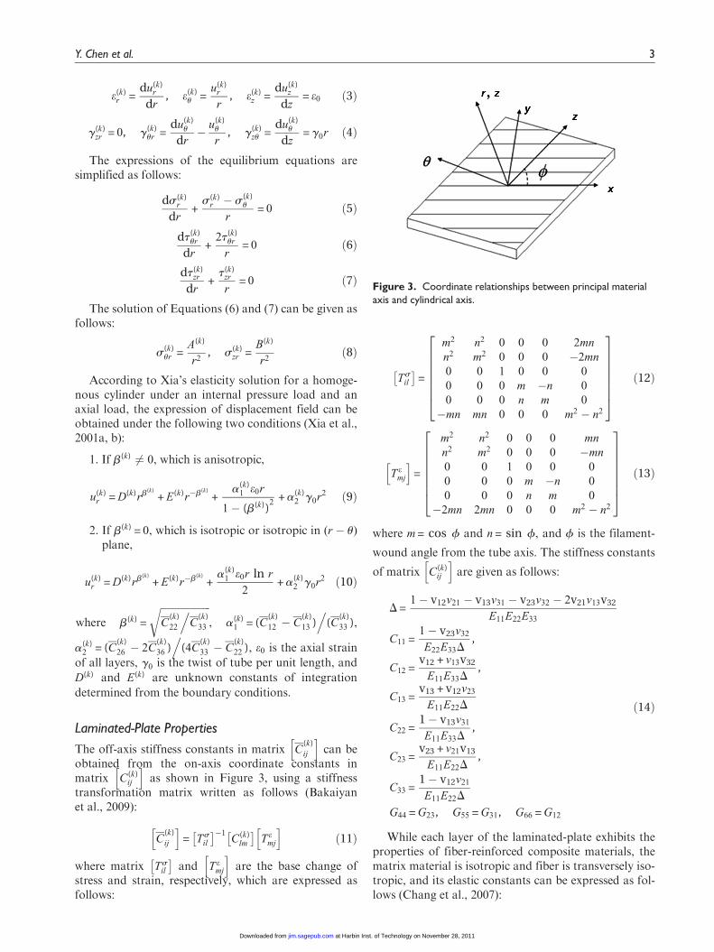
h ias shown in Figure 3, using a stiffness
transformation matrix written as follows (Bakaiyanet al., 2009):
C(k)
ij
h i= T s
il
� ��1C(k)
lm
� �T e
mj
h ið11Þ
where matrix Tsil
� �and T e
mj
h iare the base change of
stress and strain, respectively, which are expressed asfollows:
Tsil
� �=
m2 n2 0 0 0 2mn
n2 m2 0 0 0 �2mn
0 0 1 0 0 0
0 0 0 m �n 0
0 0 0 n m 0
�mn mn 0 0 0 m2 � n2
26666664
37777775
ð12Þ
T emj
h i=
m2 n2 0 0 0 mn
n2 m2 0 0 0 �mn
0 0 1 0 0 0
0 0 0 m �n 0
0 0 0 n m 0
�2mn 2mn 0 0 0 m2 � n2
26666664
37777775ð13Þ
where m = cos f and n = sin f, and f is the filament-
wound angle from the tube axis. The stiffness constants
of matrix C(k)ij
h iare given as follows:
D =1� v12v21 � v13v31 � v23v32 � 2v21v13v32
E11E22E33
C11 =1� v23v32
E22E33D,
C12 =v12 + v13v32
E11E33D,
C13 =v13 + v12v23
E11E22D
C22 =1� v13v31
E11E33D,
C23 =v23 + v21v13
E11E22D,
C33 =1� v12v21
E11E22D
G44 = G23, G55 = G31, G66 = G12
ð14Þ
While each layer of the laminated-plate exhibits theproperties of fiber-reinforced composite materials, thematrix material is isotropic and fiber is transversely iso-tropic, and its elastic constants can be expressed as fol-lows (Chang et al., 2007):
Figure 3. Coordinate relationships between principal materialaxis and cylindrical axis.
Y. Chen et al. 3
at Harbin Inst. of Technology on November 28, 2011jim.sagepub.comDownloaded from
where Ef 11, Ef 22, Gf 12, Gf 23, vf 12, and vf 23 are the mate-rial constants of fiber; Em, vm, and Gm are the materialconstants of matrix; and Vf and Vm are the volume frac-tion of fiber and matrix material.
Boundary Conditions
It is assumed that the stress and displacement field arecontinuous. All the unknown constants in stress, strain,and displacement expressions will be determined by theboundary conditions. The stress boundary conditionson both inner and outer surfaces are expressed as fol-lows (Xia et al., 2001a):
s(1)r (ra) = � P, s(n)
r (rb) = 0, t(1)zr (ra) = t(1)
ur (ra) = 0,
t(n)zr (rb) = t(n)
ur (rb) = 0 ð16Þ
where ra and rb are the inner and outer radii,respectively.
If the outer FMC laminate and inner liner are per-fectly bound, the continuity conditions for stress anddisplacement in the interfaces are given by
u(k)r (rk) = u(k + 1)
r (rk), u(k)u (rk) = u(k + 1)
u (rk)
s(k)r (rk) = s(k + 1)
r (rk), t(k)zr (rk) = t(k + 1)
zr (rk),
t(k)ur (rk) = t(k + 1)
ur (rk)
ð17Þ
In addition, the two integral conditions can beexpressed as follows:
2pXn
k = 1
ðrk
rk�1
s(k)z (r)r dr = pr2
aP + Fex ð18Þ
2pXn
k = 1
ðrk
rk�1
t(k)zu (r)r2 dr = 0 ð19Þ
Due to internal pressure with the end loading effect fora cylinder, the first integral condition satisfies the equili-brium of axial force, and the second equation is consid-ered to be the zero torsion condition.
According to the expression of stress boundaryconditions, the unknown integration constantsA(k) = B(k) = 0. For N-layered composite tube, thereare 2N + 3 unknown constants of integration, that is,D(k), E(k) (k = 1, 2, ., N), and g0, P, Fex. These
unknown constants can be determined by 2N + 2equations of boundary conditions and an additionalequation for compressible fluid. Assuming there is aF2MC tube with N (N = 5) layers, 2(N + 1) equationscan be given as follows:
D(1)
D(2)
D(3)
D(4)
D(5)
E(1)
E(2)
E(3)
E(4)
E(5)
e0
g0
8>>>>>>>>>>>>>>>>>><>>>>>>>>>>>>>>>>>>:
9>>>>>>>>>>>>>>>>>>=>>>>>>>>>>>>>>>>>>;
=
k11 k12 k13 k14 k15 k16 k17 k18 k19 k10 k1a k1b
k21 k22 k23 k24 k25 k26 k27 k28 k29 k20 k2a k2b
k31 k32 k33 k34 k35 k36 k37 k38 k39 k30 k3a k3b
k41 k42 k43 k44 k45 k46 k47 k48 k49 k40 k4a k4b
k51 k52 k53 k54 k55 k56 k57 k58 k59 k50 k5a k5b
k61 k62 k63 k64 k65 k66 k67 k68 k69 k60 k6a k6b
k71 k72 k73 k74 k75 k76 k77 k78 k79 k70 k7a k7b
k81 k82 k83 k84 k85 k86 k87 k88 k89 k80 k8a k8b
k91 k92 k93 k94 k95 k96 k97 k98 k99 k90 k9a k9b
k01 k02 k03 k04 k05 k06 k07 k08 k09 k00 k0a k0b
ka1 ka2 ka3 ka4 ka5 ka6 ka7 ka8 ka9 ka0 kaa kab
kb1 kb2 kb3 kb4 kb5 kb6 kb7 kb8 kb9 kb0 kba kbb
26666666666666666664
37777777777777777775
�1
�P
0
0
0
0
0
0
0
0
0pr2
aP + Fex
2p
0
8>>>>>>>>>>>>>>>>>><>>>>>>>>>>>>>>>>>>:
9>>>>>>>>>>>>>>>>>>=>>>>>>>>>>>>>>>>>>;
ð20Þ
where kij are the coefficients of unknown constants andcan be obtained by the equations of boundary condi-tions. Based on these unknown constants, the stress,strain, and displacement can be determined from equili-brium equations, strain–displacement expressions, dis-placement expressions, and stress–strain relationships.
Equation for Compressible Fluid
When the valve of the F2MC tube is closed, the fluidinside the inner liner will be compressed with anapplied load of Fex. As a result, the volume of the tubewill be changed by DV . In addition, the pressure of theenclosed fluid will be increased from zero to P. Therelationship of fluid and pressure can be expressed asfollows (Shan et al., 2009):
BDV
V0
� �= � P ð21Þ
4 Journal of Intelligent Material Systems and Structures XX(X)
at Harbin Inst. of Technology on November 28, 2011jim.sagepub.comDownloaded from
where B and V0 are the bulk modulus and volume ofthe fluid, respectively. Neglecting the higher order ofstrain caused by compression, the expression can besimplified as
B e(1)z (ra) + 2e(1)
u (ra)� �
= � P ð22Þ
Effective Modulus and Modulus Ratio of the F2MCTube
Once these 2N + 3 unknown constants are determined,the effective closed-valve modulus of Eclose
z and open-valve modulus of Eopen
z in the axial direction is definedas (Shan et al., 2007)
Eclosez =
Fcloseex
pr2be0
, Eopenz =
Fopenex
pr2be0
, ð23Þ
When the entire F2MC tube is uniformly stretchedto a target strain of e0, a load of Fclose
ex should be appliedunder the closed-valve state. Similarly, a load of Fopen
ex
should be applied under the open-valve state, whichmeans the pressure P is zero. Based on this fact, theeffective modulus ratio R is defined as follows:
R =Eclose
z
Eopenz
ð24Þ
F2MC Tube Fabrication and Tensile Test
F2MC Tube Fabrication
The F2MC tube was wet filament wound using acomputer-controlled filament-winding machine(SKLCR 120/500, Qier Machine Tool Group Co.,Ltd.) as shown in Figure 4. Before filament winding, athin rubber inner liner is placed on the mandrel andthen the two ends of the mandrel were fixed by three-jaw chucks with stainless steel connections. The carbonfiber (T300, 3K) was winded on the mandrel at 6f
angle through the control of computer. The uncured
silicone raw material was brushed on the surface of themandrel during the filament-wound procedure. Aftercuring at the room temperature for 35 h, the F2MCtube specimen was obtained as shown in Figure 5, witha fiber volume fraction of the outer FMC tube of 0.7.
Tensile Test
In this session, the F2MC tubes with a length of160 mm, an outer diameter of 7.8 mm, and an innerdiameter of 5 mm were tested to investigate theirmechanical properties at two states: closed valve andopen valve. Two hydraulic fittings with right size wereinserted and glued with epoxy glue to both ends of thetube. In order to ensure the fluid tightness and sustainlarge axial loads, two stainless steel clamp collars wereplaced on the surface of the two ends to clamp the tubeand hydraulic fittings together. Two screw plugs will bescrewed into the hydraulic fittings after the fluid isfilled with the tube to achieve the closed-valve condi-tion. Tensile test was performed at 25�C at a constantrate of 2 mm/min on a Materials Testing Machine (T1-FR050TH A1K, ZWICK), as shown in Figure 6. Thevalues of force and displacement were recorded usingthe computer during the tensile test.
Results and Discussion
Elastic Constants of FMC Layer
The basic material and geometry parameters of fiberand matrix are listed in Table 1. If each layer of FMClaminate is considered to be fiber-reinforced composite,their elastic constants with different fiber volume frac-tions can be obtained by substituting the parametersinto Rule of Mixture expression of Equation (15).
Experiment and Analysis Result of a SingleF2MC Tube
The experimental setup for tensile test of the F2MCtube is shown in Figure 6. The fiber volume fraction ofthe outer FMC tube is 0.7 and the filament-wound
Figure 4. Filament wound of the F2MC tube.
Figure 5. The F2MC tube specimens.
Y. Chen et al. 5
at Harbin Inst. of Technology on November 28, 2011jim.sagepub.comDownloaded from
angle is 635�. The apparent stress in the figure iscalculated as the tensile force divided by the entirecross-sectional area of the F2MC tube. The strain isapproximated as the displacement divided by the origi-nal length of the F2MC tube. The curve of apparentstress versus strain is depicted in Figure 7. In order toexactly describe the actual situation, a F2MC tube withN (N = 3, 5, 7) layers is assumed in the analysis proce-dure. The effective modulus and modulus ratio arecompared with the reference study (Shan et al., 2007)and experiment result, as shown in Table 2. The com-parison shows that the developed 3D analytical methodcan describe the experiment result accurately when thelayer N is higher than 5. In order to maintain the accu-racy of a 3D analytical method and simplify the calcula-tion process, seven layers of F2MC tube is constructedin the following analysis procedure.
Analysis and Discussion of a F2MC Tube withDifferent Conditions
Fiber Volume Fraction. To further reveal the effect offiber volume fraction on the effective modulus and
modulus ratio, a series of curves about modulus andmodulus ratio under the states of closed valve and openvalve are shown in Figures 8 and 9. Only one of thematerial and geometry parameters has been discussedfor each time, while other parameters remain constant.In order to show that the analysis results of this studyand the reference (Shan et al., 2007) are comparable,the basic material and geometry parameters ofFigures 8 and 9 are obtained based on the data shownin Table 3, except the property values of FMC laminathat are replaced by the carbon fiber (T300) and matrix(silicone) in Table 1. It is observed from Figure 8(a)that when the fiber volume fraction is a constant, theclosed-valve modulus exhibits a trend of decrease firstand then increases with the increase in fiber angle. Theminimum value appears at the point where fiber-winding angle is 55� , which has also been certified bythe description of Philen et al. (2006). This phenom-enon is mainly attributed to the reason that 55� fiber-winding angle is the boundary point of positive andnegative internal pressures resulted from the tensileaxial force. A negative change in internal pressure willbe resulted from the tensile axial force for fiber-windingangle higher than 55�, and a positive change in internal
Figure 6. The F2MC tube experiment setup.
Figure 7. Experiment curves of apparent stress versus strain ofthe F2MC tube.
Table 1. Basic material and geometry parameters of fiber and matrix.
pressure for fiber-winding angle lower than 55�. In thismanner, a fiber-winding angle of 55� should be thepoint where no pressure is produced. Besides, theclosed-valve modulus increases along with the increasein fiber volume fraction when the fiber-winding angle isa constant. Similar phenomenon exists in the curves ofFigure 8(b). It can also be found from Figure 8(b) thatwhen the fiber volume fraction is a constant, the open-valve modulus decreases rapidly for the fiber-windingangle lower than 55� and approaches to a constant forthe fiber-winding angle higher than 55� with theincrease in fiber-winding angle. Figure 9 indicates thatthe maximum modulus ratio can change from 20 to 80with different fiber volume fractions. The maximummodulus ratio increases with the decreasing fiber vol-ume fraction, but the increase in range becomes lessand less.
Fluid (Bulk Modulus B and Radius t1). In order to com-pare the analysis result with reference, the basic mate-rial and geometry parameters in the followingdiscussions will be fitted the same value as those in ref-erence (Shan et al., 2007), as shown in Table 3. As one
of the component parts, the material and geometryproperties of fluid play an important role in the stiff-ness variation of the F2MC tube. The variable stiffnessability of the F2MC tube is mainly due to the high bulkmodulus of fluid and the high anisotropy of the FMCtube. The curves of closed-valve and open-valve moduliversus fiber angle of the F2MC tube with different bulkmoduli of fluid are shown in Figure 10(a). It is revealedthat when the bulk modulus is a constant, the closed-valve and open-valve moduli exhibit a trend of firstdecreasing rapidly and then increasing slowly alongwith the increase in fiber angle. The closed-valve modu-lus increases along with the increase in bulk moduluswhen fiber-winding angle is a constant. Consideringthat the variation of bulk modulus has no effect on theopen-valve modulus, only one bulk modulus is shownin Figure 10(a) under open-valve condition. The rela-tionship between the modulus ratio and fiber angle ofthe F2MC tube with different bulk moduli of fluid isdepicted in Figure 10(b). Along with the increase inbulk modulus, the maximum modulus ratio has greatlyincreased. The modulus ratio does not increase remark-ably when the bulk modulus is larger than 500 MPa. Inaddition, the change in phenomenon of modulus ratioin Figure 10(b) based on this study fits exactly with thecorresponding results that are demonstrated in the ref-erence (Shan et al., 2007).
Figure 11(a) shows the curves of closed-valve andopen-valve moduli versus fiber angle of the F2MC tubewith different radii of fluid. It is revealed that theclosed-valve modulus increases along with the increasein radius when fiber-winding angle is a constant. It ismainly attributed to the relative increase of the fluidvolume and the relative decrease of the inner liner vol-ume and FMC tube volume. Moreover, such change of
Table 2. Effective modulus and modulus ratio results: Analysisand experiment.
Figure 8. Curves of modulus versus fiber angle of the F2MC tube with different fiber volume fractions: (a) closed-valve modulus and(b) open-valve modulus.
Y. Chen et al. 7
at Harbin Inst. of Technology on November 28, 2011jim.sagepub.comDownloaded from
relative volume has a positive effect on the increase inclosed-valve modulus. However, the open-valve modu-lus decreases with the increase in radius. The main rea-son of such result is the decreased volume fraction ofthe FMC tube. The relationship between the modulusratio and fiber angle of the F2MC tube with differentradii of fluid is depicted in Figure 11(b). Along with theincrease in radius, the maximum modulus ratio is uni-formly increased when the radius is a constant. Withthe radius changing from 3 to 7 mm, the maximummodulus ratio reaches up to 120.
Inner Liner (Elastic Modulus E, Thickness t2, and Poisson’sRatio v). The primary function of inner liner is to pre-vent fluid from leakage, and its material and geometryparameter change also plays a significant role on themodulus and modulus ratio. As an isotropic material,the elastic modulus of inner liner should be first consid-ered. The curves of closed-valve and open-valve moduliversus fiber angle of the F2MC tube with different elas-tic moduli of inner liner are shown in Figure 12(a). Asseen in Figure 12(a), both closed-valve and open-valvemoduli are increased with the increase in elastic modu-lus of inner liner while the fiber-winding angle is a con-stant. The relationship between the modulus ratio andfiber angle of the F2MC tube with different elasticmoduli of inner liner is depicted in Figure 12(b). Alongwith the increase in elastic modulus, the maximummodulus ratio presents the trend of first increases andthen decreases. Along with the increase in the innerliner modulus, it will be more difficult to compress theinner liner under closed-valve state, and then a highmodulus ratio is obtained, which results from the gen-erated high internal pressure. However, the high
Figure 9. Curves of modulus ratio versus fiber angle of theF2MC tube with different fiber volume fractions.
Table 3. Basic material and geometry parameters in reference.
Fluid B (GPa) 2Geometry Outer diameter of fluid (mm) 10
Outer diameter of inner liner (mm) 12Outer diameter of FMC (mm) 13
Figure 10. Curves of modulus versus fiber angle of the F2MC tube with different bulk moduli of fluid: (a) closed-valve and open-valvemoduli and (b) modulus ratio.
8 Journal of Intelligent Material Systems and Structures XX(X)
at Harbin Inst. of Technology on November 28, 2011jim.sagepub.comDownloaded from
modulus ratio will decrease along with the increase inthe open-valve modulus, which results from the exces-sive increase in inner liner modulus. In addition, thechange in regularity of modulus ratio in Figure 12(b)based on this study fits exactly with the correspondingresults in the reference (Shan et al., 2007).
Figure 13(a) shows the curves of closed-valve andopen-valve moduli versus fiber angle of the F2MC tubewith different thicknesses of inner liner. Both theclosed-valve and open-valve moduli decrease with theincrease in thickness of inner liner when fiber-windingangle is a constant. For the modulus of the inner lineris far lower than the fluid, it will be more easy to
compress the inner liner under closed-valve state. As aresult, the increase in the thickness of inner liner resultsin a more volume reduction of inner liner under highinternal pressure, causing the closed-valve modulus todecrease. The relation between the modulus ratio andfiber angle of the F2MC tube with different thicknessesof inner liner is depicted in Figure 13(b). It can beobserved that the smaller the thickness of inner liner,the larger the maximum modulus ratio is. Therefore, inorder to improve the modulus ratio of the F2MC tube,it is important to decrease the thickness of inner liner.
The curves of closed-valve and open-valve moduliversus fiber angle of the F2MC tube with different
Figure 11. Curves of modulus versus fiber angle of the F2MC tube with different radii of fluid: (a) closed-valve and open-valve moduliand (b) modulus ratio.
Figure 12. Curves of modulus versus fiber angle of the F2MC tube with different elastic moduli of inner liner: (a) closed-valve andopen-valve moduli and (b) modulus ratio.
Y. Chen et al. 9
at Harbin Inst. of Technology on November 28, 2011jim.sagepub.comDownloaded from
Poisson’s ratios of inner liner are shown in Figure14(a). It can be found that the increase in Poisson’sratio plays a positive contribution to the increase in theclosed-valve modulus, that is, the increase in Poisson’sratio makes no difference to the open-valve modulus.As seen in the curves of modulus ratio versus fiber angleof the F2MC tube with different Poisson’s ratios ofinner liner in Figure 14(b), the maximum modulus ratioincreases with the increase in Poisson’s ratio. Withinthe variation range of Poisson’s ratio, the increasingspeed of modulus ratio for the Poisson’s ratio morethan 0.475 is larger than that for the Poisson’s ratio lessthan 0.475.
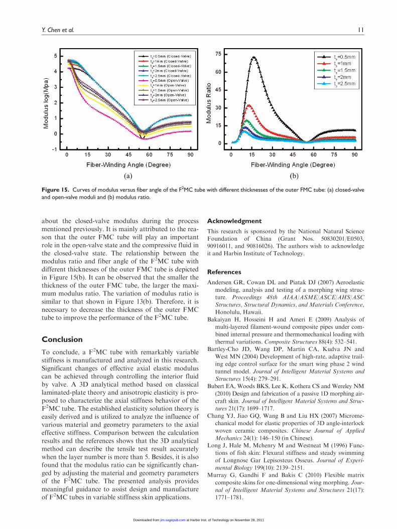
Outer FMC Tube (Thickness t3). As mentioned previ-ously, one of the primary reasons resulting in the abilityof variable stiffness is the high anisotropy of the FMCtube. Clearly, thickness should be one of the factorsthat has an effect on the modulus ratio of the F2MCtube. For simplicity, only thickness of the outer FMCtube is discussed in this section. The curves of closed-valve and open-valve moduli versus fiber angle of theF2MC tube with different thicknesses of the outerFMC tube are shown in Figure 15(a). Along with theincrease in the thickness of the outer FMC tube, theopen-valve modulus increases when the fiber-windingangle is a constant. But there is no significant change
Figure 13. Curves of modulus versus fiber angle of the F2MC tube with different thicknesses of inner liner: (a) closed-valve andopen-valve moduli and (b) modulus ratio.
Figure 14. Curves of modulus versus fiber angle of the F2MC tube with different Poisson’s ratios of inner liner: (a) closed-valve andopen-valve moduli and (b) modulus ratio.
10 Journal of Intelligent Material Systems and Structures XX(X)
at Harbin Inst. of Technology on November 28, 2011jim.sagepub.comDownloaded from
about the closed-valve modulus during the processmentioned previously. It is mainly attributed to the rea-son that the outer FMC tube will play an importantrole in the open-valve state and the compressive fluid inthe closed-valve state. The relationship between themodulus ratio and fiber angle of the F2MC tube withdifferent thicknesses of the outer FMC tube is depictedin Figure 15(b). It can be observed that the smaller thethickness of the outer FMC tube, the larger the maxi-mum modulus ratio. The variation of modulus ratio issimilar to that shown in Figure 13(b). Therefore, it isnecessary to decrease the thickness of the outer FMCtube to improve the performance of the F2MC tube.
Conclusion
To conclude, a F2MC tube with remarkably variablestiffness is manufactured and analyzed in this research.Significant changes of effective axial elastic moduluscan be achieved through controlling the interior fluidby valve. A 3D analytical method based on classicallaminated-plate theory and anisotropic elasticity is pro-posed to characterize the axial stiffness behavior of theF2MC tube. The established elasticity solution theory iseasily derived and is utilized to analyze the influence ofvarious material and geometry parameters to the axialeffective stiffness. Comparison between the calculationresults and the references shows that the 3D analyticalmethod can describe the tensile test result accuratelywhen the layer number is more than 5. Besides, it is alsofound that the modulus ratio can be significantly chan-ged by adjusting the material and geometry parametersof the F2MC tube. The presented analysis providesmeaningful guidance to assist design and manufactureof F2MC tubes in variable stiffness skin applications.
Acknowledgment
This research is sponsored by the National Natural Science
Foundation of China (Grant Nos. 50830201/E0503,90916011, and 90816026). The authors wish to acknowledgeit and Harbin Institute of Technology.
References
Andersen GR, Cowan DL and Piatak DJ (2007) Aeroelastic
modeling, analysis and testing of a morphing wing struc-
ture. Proceedings 48th AIAA/ASME/ASCE/AHS/ASC
Structures, Structural Dynamics, and Materials Conference,
Honolulu, Hawaii.Bakaiyan H, Hosseini H and Ameri E (2009) Analysis of
multi-layered filament-wound composite pipes under com-
bined internal pressure and thermomechanical loading with
thermal variations. Composite Structures 88(4): 532–541.Bartley-Cho JD, Wang DP, Martin CA, Kudva JN and
West MN (2004) Development of high-rate, adaptive trail-
ing edge control surface for the smart wing phase 2 wind
tunnel model. Journal of Intelligent Material Systems and
Structures 15(4): 279–291.Bubert EA, Woods BKS, Lee K, Kothera CS and Wereley NM
(2010) Design and fabrication of a passive 1D morphing air-
craft skin. Journal of Intelligent Material Systems and Struc-
tures 21(17): 1699–1717.Chang YJ, Jiao GQ, Wang B and Liu HX (2007) Microme-
chanical model for elastic properties of 3D angle-interlock
woven ceramic composites. Chinese Journal of Applied
Mechanics 24(1): 146–150 (in Chinese).Long J, Hale M, Mchenry M and Westneat M (1996) Func-
tions of fish skin: Flexural stiffness and steady swimming
of Longnose Gar Lepisosteus Osseus. Journal of Experi-
mental Biology 199(10): 2139–2151.Murray G, Gandhi F and Bakis C (2010) Flexible matrix
composite skins for one-dimensional wing morphing. Jour-
nal of Intelligent Material Systems and Structures 21(17):
1771–1781.
Figure 15. Curves of modulus versus fiber angle of the F2MC tube with different thicknesses of the outer FMC tube: (a) closed-valveand open-valve moduli and (b) modulus ratio.
Y. Chen et al. 11
at Harbin Inst. of Technology on November 28, 2011jim.sagepub.comDownloaded from
tures, Structural Dynamics and Materials Conference,Newport, Rhode Island.
Philen M, Shan Y, Wang KW, Bakis CE and Rahn CD(2007) Fluidic flexible matrix composites for the tailoringof variable Stiffness Adaptive Structures. Proceedings 48thAIAA/ASME/ASCE/AHS/ASC Structures, Structural
Dynamics and Materials Conference, Honolulu, Hawaii.Reich GW, Sanders B and Joo JJ (2007) Development of
skins for morphing aircraft applications via topology opti-
mization. Journal of Intelligent Material Systems and
Structures 20(April): 1–13.Shan Y, Lotfi A, Philen M, Li SY, Bakis CE, Rahn CD, et al.
(2007) Fluidic flexible matrix composites for autonomous
structural tailoring. Proceedings of SPIE, the International
Society for Optical Engineering 6525: 1–14.Shan Y, Philen M, Lotfi A, Li SY, Bakis CE, Rahn CD, et al.