Journal of Robotics and Mechanical Engineering Research
Performance Analysis of Cold Sections of High BYPASS Ratio Turbofan Aeroengine
Ahmed F. El-sayed*, Mohamed S. Emeara and Mohamed K. Fayed
Department of Mechanical Power, Engineering College, Zagazig University, Egypt
www.verizonaonlinepublishing.com
J Robot Mech Eng Resr Page | 18
*Corresponding author: Ahmed F. El-sayed, Department of Mechanical Power, Engineering College,Zagazig University, Zagazig 44519, Egypt; E mail: [email protected]
Article Type: Case Report, Submission Date: 04 August 2017, Accepted Date: 28 August 2017, Published Date: 31 October 2017.
Citation: Ahmed F. El-sayed, Mohamed S. Emeara and Mohamed K. Fayed (2017) Performance Analysis of Cold Sections of High BYPASS Ratio Turbofan Aeroengine. J Robot Mech Eng Resr 2(1): 18-27. doi: https://doi.org/10.24218/jrmer.2017.23.
The turbofan engine had many developments in the past 60 years and becomes the common power plant employed in both civil airliners and military aircrafts. It combines the advantages of both of turboprop engines (high propulsive efficiency and thrust) and turbojet engines (high flight speed and altitude). To cope with the needs of high thrust forces that propel wide body airliner and increase of their payload and range as well as enlarging maneuver capabilities of military aircrafts, successive developments of turbofan engines are needed. These developments in turbofan design have endeavors of larger thrust force, low noise and emission as well as better fuel economy. These goals were achieved by increasing of the bypass ratio (BR), fan pressure ratio (FPR), overall pressure ratio (OPR), turbine inlet temperature (TIT) as well as using new materials, production and cooling techniques for both turbines and combustion chamber such modifications led to improvements in thermal, propulsive and overall efficiencies, decreases in thrust specific fuel consumption (TSFC) and increase the specific thrust. This paper presents a parametric study and design point selection of the cold sections of high bypass ratio turbofan engine (close to GEnx-1B-70). Cold sections include the intake, the fan, and the compressor. This engine is one of the products of GE Aviation Company. Performance analysis is performed using MATLAB program code for both taking-off and cruise conditions.
Introduction
The bypass turbofan GE design was conceived to improve the fuel efficiency for commercial aircraft. An additional component – the fan – is installed at the inlet of the engine to increase the amount of air flowing through the engine. However, part of the inlet airflow is not directed toward the compressor, combustor, and turbine, but is rather bypassed through a duct, which ends in a nozzle. Since air leaves the nozzle at a speed which is higher than the intake velocity, thrust is produced by momentum
exchange with the airframe. The flow which is not bypassed undergoes the processes mentioned in the turbojet section, producing part of the total thrust. Note that the thrust generated by the bypass flow does not require the burning of fuel, but some mechanical work must be derived from a turbine to drive the fan. Turbofans can be classified according to number of spools or weather the two jets are mixed among other criteria. From the first turbo supercharger to the world’s most powerful commercial jet engine, GE’s history of powering aircraft spans nearly a century of innovation GE Aviation is a world-leading provider of commercial and militaryjet engines and components as well as integrated digital, electric power, and mechanical systems for aircraft. GE Aviation also has a global service network to support these offerings Technological excellence, supported by continued investments in research and development, hasbeen the foundation of GE Aviation’s growth and helps to ensure quality products for customers well into the future.
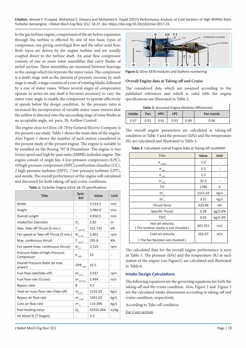
In the present paper the components of (GEnX-1B70) turbine engine will discussed as: 1- Intake, 2- Fan, 3- Compressor, 4- Combustion Chamber, 5- Turbine, and 6- Nozzle. They will discuss briefly in the following sections.
Engine intake compatibility covers the mutual dependencies between the aircraft intake and the gas turbine. Besides exhibiting optimal performance it is of utmost importance that stable propulsion operation in the whole flight envelope of a jet aircraft is ensured. In this chapter the effects of intake flow distortions on the operation conditions of engine components and the whole gas turbine will be described there are three types of intakes subsonic or supersonic and hypersonic note (GEnx-1B-70) subsonic intake.
Fans have progressed through the years but here we discus two important fans; this of the GE90 engine and that of the GEnXengine there are fan materials titanium or bi-metals and composite.
Citation: Ahmed F. El-sayed, Mohamed S. Emeara and Mohamed K. Fayed (2017) Performance Analysis of Cold Sections of High BYPASS Ratio Turbofan Aeroengine. J Robot Mech Eng Resr 2(1): 18-27. doi: https://doi.org/10.24218/jrmer.2017.23.
In the gas turbine engine, compression of the air before expansion through the turbine is effected by one of two basic types of compressor, one giving centrifugal flow and the other axial flow. Both types are driven by the engine turbine and are usually coupled direct to the turbine shaft. An axial flow compressor consists of one or more rotor assemblies that carry blades of airfoil section. These assemblies are mounted between bearings in the casings which incorporate the stator vanes. The compressor is a multi-stage unit as the amount of pressure increase by each stage is small; a stage consists of a row of rotating blades followed by a row of stator vanes. Where several stages of compression operate in series on one shaft it becomes necessary to vary the stator vane angle to enable the compressor to operate effectively at speeds below the design condition. As the pressure ratio is increased the incorporation of variable stator vanes ensures that the airflow is directed onto the succeeding stage of rotor blades at an acceptable angle, ref. para. 30, Airflow Control.
The engine close to GEnx-1B-70 by General Electric Company is the present case study. Table 1 shows the main data of the engine. Also Figure 1 shows the number of each station considered in the present study of the present engine. The engine is suitable to be installed on the Boeing 787-8 Dreamliner. The engine is two (twin) spool and high by-pass ratio (HBPR) turbofan engine. The engine consist of single fan, 4 low-pressure compressors (LPC), 10 high-pressure compressors (HPC),combustion chamber (CC), 2 high-pressure turbines (HPT), 7 low-pressure turbines (LPT), and nozzle. The overall performance of the engine will calculated and discussed for both taking-off and cruise conditions.
Fan speed at Take-off Thrust (5 min.) N f--TO 2,401 rpm
Max. continuous thrust T max-C 295.8 KN
Fan speed (max. continuous thrust) N f-C 2,319 rpm
Pressure Ratio of High-Pressure Compressor π HPC 23 -
Overall Pressure Ratio (at max. power) OPR Max 43.5 -
Fuel flow rate(Take-off) m ̇f-TO 2.037 rpm
Fuel flow rate (Cruise) m f-Cruise 2.494 m/s
Bypass ratio β 9.1 -
Total air mass flow rate (Take-off) ma-TO 1155.43 kg/s
Bypass air flow rate m a-BP 1041.03 kg/s
Core air flow rate m ̇a 114.399 kg/s
Fuel heating value QR 42555.066 kJ/kg
Air bleed % (7 Stages) - 3.3 -
Figure 1: GEnx-1B70 modules and Stations numbering
Overall Engine data at Taking-off and Cruise
The considered data which are assumed according to the published references and which is valid with the engine specifications are illustrated in Table 2.
Table 2: Assumed Engine Modules EfficienciesIntake Fan HPC LPC Fan nozzle
0.97 0.91 0.91 0.91 0.99 0.96
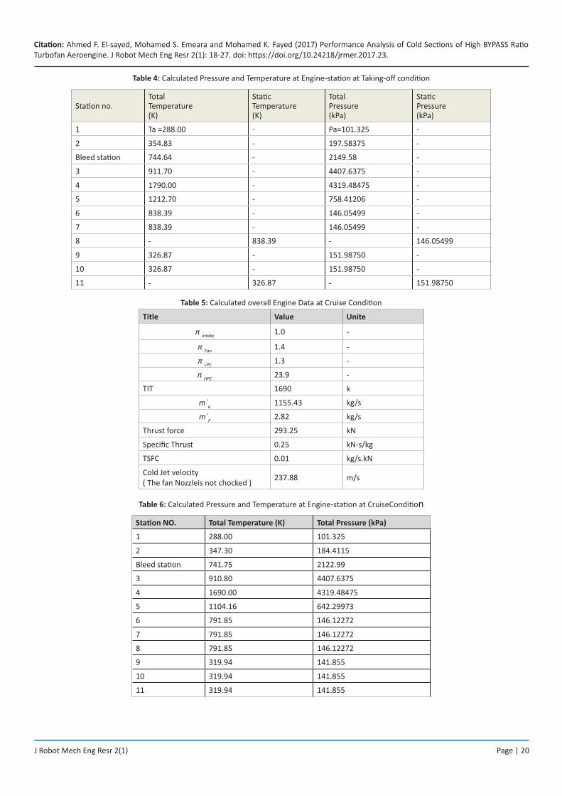
The overall engine parameters are calculated at taking-off condition in Table 3 and the pressure (kPa) and the temperature (K) are calculated and illustrated in Table 4.
Table 3: Calculated overall Engine Data at Taking-off condition
Title Value Unit
π intake 1.0 -
π Fan 1.5 -
π LPC 1.3 -
π HPC 22.3 -
TIT 1790 K
m`a 1155.43 kg/s
m`F 3.21 kg/s
Thrust force 320.48 kN
Specific Thrust 0.28 kg/S.KN
TSFC 0.01 kg/S.KN
Hot Jet velocity( The turbine nozzle is not chocked ) 401.921 m/s
Cold Jet velocity
( The fan Nozzleis not chocked )
262.67 m/s
The calculated data for the overall engine performance is seen in Table 5. The pressure (kPa) and the temperature (K) at each station of the engine (see Figure1) are calculated and illustrated in Table 6.
Intake Design Calculations
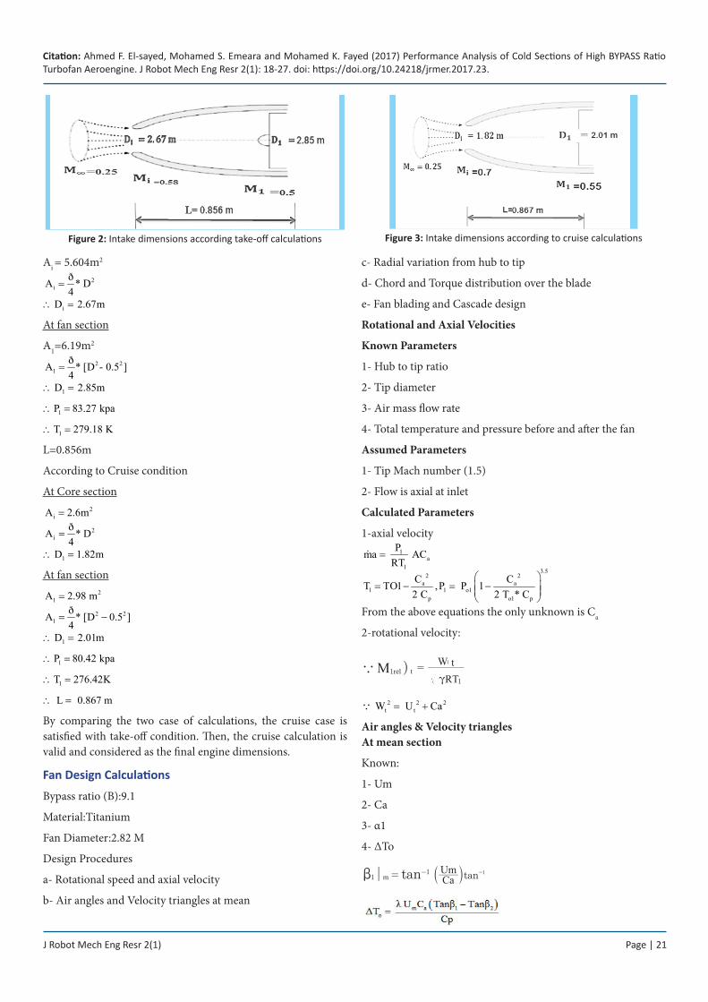
The following equations are the governing equations for both the taking-off and the cruise condition. Also, Figure 2 and Figure 3 are the calculated intake dimensions according to taking-off and cruise condition, respectively.
According to Take-off condition
For Core section
J Robot Mech Eng Resr 2(1) Page | 20
Citation: Ahmed F. El-sayed, Mohamed S. Emeara and Mohamed K. Fayed (2017) Performance Analysis of Cold Sections of High BYPASS Ratio Turbofan Aeroengine. J Robot Mech Eng Resr 2(1): 18-27. doi: https://doi.org/10.24218/jrmer.2017.23.
Table 4: Calculated Pressure and Temperature at Engine-station at Taking-off condition
Station no.Total Temperature (K)
Static Temperature (K)
Total Pressure (kPa)
Static Pressure (kPa)
1 Ta =288.00 - Pa=101.325 -
2 354.83 - 197.58375 -
Bleed station 744.64 - 2149.58 -
3 911.70 - 4407.6375 -
4 1790.00 - 4319.48475 -
5 1212.70 - 758.41206 -
6 838.39 - 146.05499 -
7 838.39 - 146.05499 -
8 - 838.39 - 146.05499
9 326.87 - 151.98750 -
10 326.87 - 151.98750 -
11 - 326.87 - 151.98750
Table 5: Calculated overall Engine Data at Cruise Condition
Title Value Unite
π intake 1.0 -
π Fan 1.4 -
π LPC 1.3 -
π HPC 23.9 -
TIT 1690 k
m`a 1155.43 kg/s
m`F 2.82 kg/s
Thrust force 293.25 kN
Specific Thrust 0.25 kN-s/kg
TSFC 0.01 kg/s.kN
Cold Jet velocity( The fan Nozzleis not chocked ) 237.88 m/s
Table 6: Calculated Pressure and Temperature at Engine-station at CruiseCondition
Station NO. Total Temperature (K) Total Pressure (kPa)
1 288.00 101.325
2 347.30 184.4115
Bleed station 741.75 2122.99
3 910.80 4407.6375
4 1690.00 4319.48475
5 1104.16 642.29973
6 791.85 146.12272
7 791.85 146.12272
8 791.85 146.12272
9 319.94 141.855
10 319.94 141.855
11 319.94 141.855
J Robot Mech Eng Resr 2(1) Page | 21
Citation: Ahmed F. El-sayed, Mohamed S. Emeara and Mohamed K. Fayed (2017) Performance Analysis of Cold Sections of High BYPASS Ratio Turbofan Aeroengine. J Robot Mech Eng Resr 2(1): 18-27. doi: https://doi.org/10.24218/jrmer.2017.23.
Ai = 5.604m2
2i
ðA * D4
=
i D 2.67m =∴
At fan section
A1=6.19m2
2 21
ðA * [D - 0.54
]=
1 D 2.85m =∴
1P 83.27 kpa∴ =
1T 279.18 K∴ =
L=0.856m
According to Cruise condition
At Core section2
iA 2.6m=2
i ðA * D4
=
1 D 1 .82m=∴
At fan section2
1A 2.98 m=2 2
1ðA * [D4
]0.5−=
1 D 2.01m =∴
1P 80.42 kpa∴ =
1T 276.42K∴ =
L 0. 867 m=∴
By comparing the two case of calculations, the cruise case is satisfied with take-off condition. Then, the cruise calculation is valid and considered as the final engine dimensions.
Fan Design Calculations
Bypass ratio (B):9.1
Material:Titanium
Fan Diameter:2.82 M
Design Procedures
a- Rotational speed and axial velocity
b- Air angles and Velocity triangles at mean
c- Radial variation from hub to tip
d- Chord and Torque distribution over the blade
e- Fan blading and Cascade design
Rotational and Axial Velocities
Known Parameters
1- Hub to tip ratio
2- Tip diameter
3- Air mass flow rate
4- Total temperature and pressure before and after the fan
Assumed Parameters
1- Tip Mach number (1.5)
2- Flow is axial at inlet
Calculated Parameters
1-axial velocity1
a1
Pma ACRT
=
3.52 2
a a1 1 o1
p o1 p
C CT TO1 ,P P 12 C 2 T * C
= − = −
From the above equations the only unknown is Ca
2-rotational velocity:
)M1rel taRT
W
1
t1
c=
2 2 2t t W U Ca= +
Air angles & Velocity triangles At mean section
Known:
1- Um
2- Ca
3- α1
4- ΔTo
| tan11
mb = - tanCaUm 1-a k
Figure 2: Intake dimensions according take-off calculations Figure 3: Intake dimensions according to cruise calculations
J Robot Mech Eng Resr 2(1) Page | 22
Citation: Ahmed F. El-sayed, Mohamed S. Emeara and Mohamed K. Fayed (2017) Performance Analysis of Cold Sections of High BYPASS Ratio Turbofan Aeroengine. J Robot Mech Eng Resr 2(1): 18-27. doi: https://doi.org/10.24218/jrmer.2017.23.
tanCaUm
2b= ^ h 2 2 2
1 1 a1W U C= +
( )cosC
Ca2
2
1
a=
( )cosW
Ca2
2
1
b=
Air angles & Velocity triangles
At mean section
Figure 4 and Figure 5 show the velocity triangles for the airfoil at tip section and mean section, respectively. Figure 6 shows velocity triangle for airfoil at hub section of the fan blade.
Figure 4: Velocity triangle for airfoil at tip section of for the fan by free vortex method
Figure 5: Velocity triangle for airfoil at mean section of the fan blade
Figure 6: Velocity triangle for airfoil at hub section of the fan blade
Radial variation from hub to tip
Table 7 shows the data of radial variation from hub to tip.
Velocity triangle:-
At Tip section
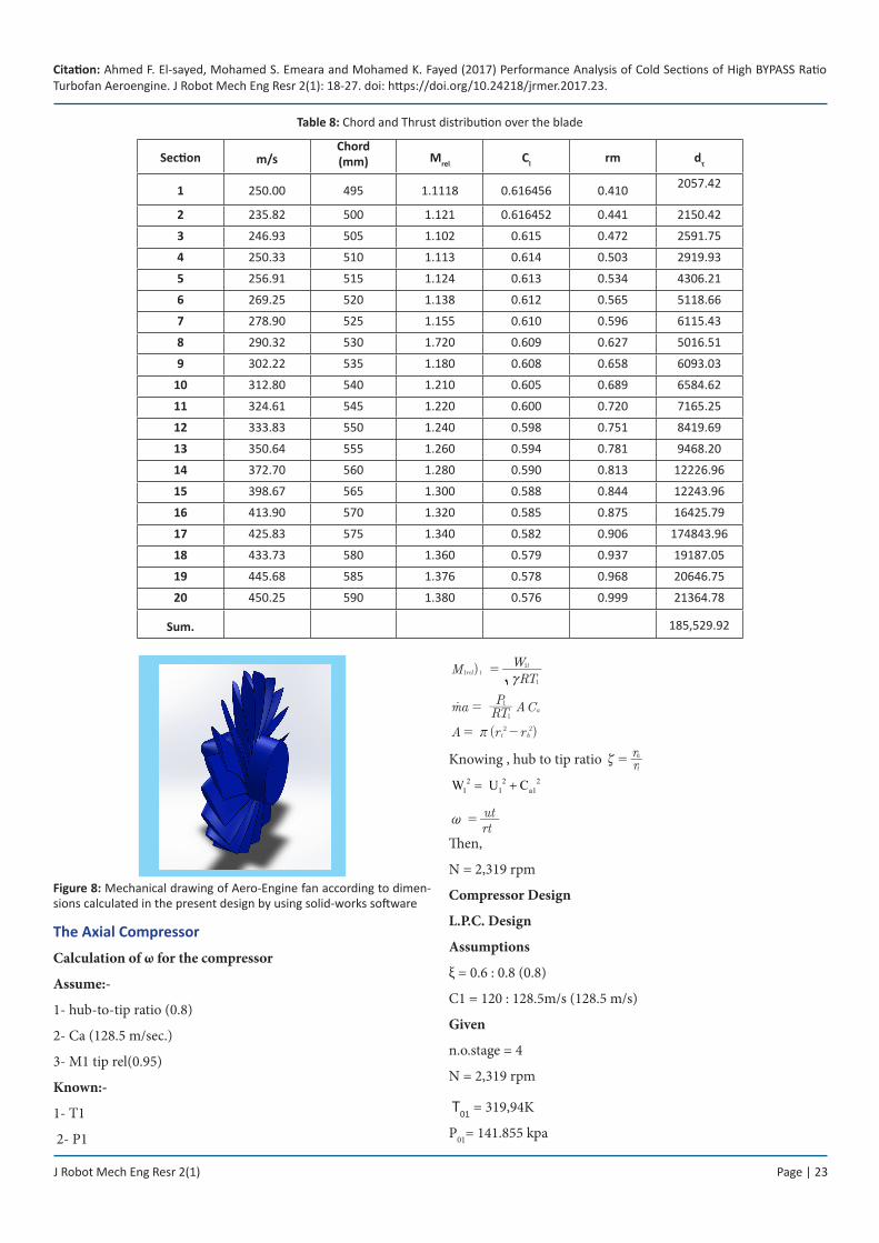
Chord and Thrust distribution over the blade
Figure 7: Dimensions of blade
The Chord distribution is assumed and then checked by comparing the fan torque to the torque from each section “20 section” where:
1- P Total torque : Tù
= =185,498.8 N.M
2- Torque from each section:
cos cosd
C cZC rdr2 m
a l2 2
2
xb
t= * cos
cos m
cb c-^ h
CL and CD are based on a NACA-65 series report for various Mach numbers and angles of attack. Table 8 shows Chord and Thrust distribution over the blade.
Fan Blading and Cascade Design
The blade twist angle
Twist angle at inlet =
β`1t−β`1h = 48.74°− 45.44° = 3.3°
Twist angle at exit = β`2t−β`2h = 32.42°- (-°29.4) =61.82°
The spacing between the fan blades
S = *n
r2 mr = * .18
2 0 91r . m0 32=
S 0.32 m∴ =
Airfoil
Root : subsonic airfoil
Tip: supersonic airfoil
sharp edges at
leading edgeortrailing edge
Figure 7 shows shows the blade dimensions and Figure 8 shows the blade which is drawing by solidworks software.
tan 2a+ ^ h
J Robot Mech Eng Resr 2(1) Page | 23
Citation: Ahmed F. El-sayed, Mohamed S. Emeara and Mohamed K. Fayed (2017) Performance Analysis of Cold Sections of High BYPASS Ratio Turbofan Aeroengine. J Robot Mech Eng Resr 2(1): 18-27. doi: https://doi.org/10.24218/jrmer.2017.23.
Figure 8: Mechanical drawing of Aero-Engine fan according to dimen-sions calculated in the present design by using solid-works software
The Axial Compressor
Calculation of ω for the compressor
Assume:-
1- hub-to-tip ratio (0.8)
2- Ca (128.5 m/sec.)
3- M1 tip rel(0.95)
Known:-
1- T1
2- P1
) MRT
Wrel t
t1
1
1
c=
ma RTP A Ca
1
1=o
( ) A r rt h2 2r= -
Knowing , hub to tip ratio rr
t
hg =
2 2 21 1 a1W U C= +
rt
ut~ =
Then,
N = 2,319 rpm
Compressor Design
L.P.C. Design
Assumptions
ξ = 0.6 : 0.8 (0.8)
C1 = 120 : 128.5m/s (128.5 m/s)
Given
n.o.stage = 4
N = 2,319 rpm
T01 = 319,94K
P01= 141.855 kpa
Table 8: Chord and Thrust distribution over the blade
Section m/sChord(mm) Mrel Cl rm dτ
1 250.00 495 1.1118 0.616456 0.410 2057.42
2 235.82 500 1.121 0.616452 0.441 2150.42
3 246.93 505 1.102 0.615 0.472 2591.75
4 250.33 510 1.113 0.614 0.503 2919.93
5 256.91 515 1.124 0.613 0.534 4306.21
6 269.25 520 1.138 0.612 0.565 5118.66
7 278.90 525 1.155 0.610 0.596 6115.43
8 290.32 530 1.720 0.609 0.627 5016.51
9 302.22 535 1.180 0.608 0.658 6093.03
10 312.80 540 1.210 0.605 0.689 6584.62
11 324.61 545 1.220 0.600 0.720 7165.25
12 333.83 550 1.240 0.598 0.751 8419.69
13 350.64 555 1.260 0.594 0.781 9468.20
14 372.70 560 1.280 0.590 0.813 12226.96
15 398.67 565 1.300 0.588 0.844 12243.96
16 413.90 570 1.320 0.585 0.875 16425.79
17 425.83 575 1.340 0.582 0.906 174843.96
18 433.73 580 1.360 0.579 0.937 19187.05
19 445.68 585 1.376 0.578 0.968 20646.75
20 450.25 590 1.380 0.576 0.999 21364.78
Sum. 185,529.92
J Robot Mech Eng Resr 2(1) Page | 24
Citation: Ahmed F. El-sayed, Mohamed S. Emeara and Mohamed K. Fayed (2017) Performance Analysis of Cold Sections of High BYPASS Ratio Turbofan Aeroengine. J Robot Mech Eng Resr 2(1): 18-27. doi: https://doi.org/10.24218/jrmer.2017.23.
T02 = 347. 30K
P02 = 184. 4115 K pa
So ΔTos = 6.84k
Cp = 1005 KJ/kg.K
γ= 1.4
R = 287
M`a = 114.399 Kg/s
By: Using Design method” first power
Table 9 shows Calculated parameters for LPC from 1st to 4th stage. Table 10 shows also the calculated parameters from the 5th stage to the 14th final stage.
Table 9: Calculated parameters for LPC from 1st to 4th stage
stage ηs λ rt (m) rm (m) rh (m) ∆T0s πs
0.91 0.98 0.398 0.304 0.211 40.25 1.43
0.91 0.93 0.376 0.304 0.233 40.25 1.38
0.91 0.88 0.362 0.304 0.248 40.25 1.34
0.91 0.83 0.351 0.304 0.259 40.25 1.31
Table 10: Calculated parameters for HPC from 5th to 14th stage
stage ηs λ rt (m) rm (m) rh (m) ∆T0s πs
- - - m m m K -
0.91 0.83 0.342 0.304 0.267 40.25 1.28
0.91 0.83 0.336 0.304 0.274 40.25 1.26
0.91 0.83 0.357 0.304 0.279 40.25 1.24
0.91 0.83 0.331 0.304 0.282 40.25 1.23
0.91 0.83 0.324 0.304 0.285 40.25 1.22
0.91 0.83 0.321 0.304 0.288 40.25 1.20
0.91 0.83 0.319 0.304 0.290 40.25 1.19
0.91 0.83 0.318 0.304 0.292 40.25 1.18
0.91 0.83 0.316 0.304 0.293 40.25 1.17
0.91 0.83 0.315 0.304 0.294 40.25 1.16
Blade Design
Cascade measurements
In order to obtain information on the effect of different blade designs on air flow angles, pressure losses and energy transfer across blade rows, one must resort to cascade wind tunnels and cascade theory. Experimentation here is performed to ensure that the blade row satisfies its objectives. The first objective is to turn air through the required angles (β1 − β2) for rotor and (α3 −α2) for stator, with the angle (β1 − β2) as a maximum as possible to maximize the stage pressure ratio. The second objective is to achieve the diffusing process with optimum efficiency, i.e., with minimum loss of stagnation pressure.
Calculation of no. of blades
We determine the number of blade at all stage and the chord length at all radii for all station. Details: For rotor we use β1&β2 and for stator we use α2&α3. Table 11 shows the calculated number of blades of each stage for LPC.
Table 11: Calculated Number of blades of each stage for LPC
stage rt (m) rh (m) H (m) C S/C S N
0.398 0.211 0.187 0.0623 2.2 0.137 14
0.376 0.233 0.143 0.047 2 0.094 20
0.362 0.248 0.114 0.038 1.8 0.068 28
0.351 0.259 0.092 0.031 1.8 0. 056 34
For Rotor:
At mean section
*f = β1 − β2We get s/c
We assume,
C= h/3 for low pressure compressor
Then,
S=(S/C)*C(Equ.16) No. of blade = (2π*rm)/S(Equ.17) From experience for rotor number of Blade is odd and for stator is even to avoid numbers with common multiples for the blades in successive rows to reduce the likelihood of introducing resonant forcing frequencies.
Where:
- Aspect ratio (h/c) is defined as hight divided by vane or blade chord.
- C The chord.
- S the space between two blades.
Table 11 shows Calculated Number of blades of each stage for LPC.
For Stator:
At mean section *f aD= We get s/c
successive rows to reduce the likelihood of introducing resonant forcing frequencies.
Where:2
aS o3
p
CT T2C
= −
P P TT
3 0303
3 1=
cc-a k
* R TP
33
3t =
* * M A C..Tot a3 3t=
A= * CM .
.
a
Tot
3 3t
J Robot Mech Eng Resr 2(1) Page | 25
Citation: Ahmed F. El-sayed, Mohamed S. Emeara and Mohamed K. Fayed (2017) Performance Analysis of Cold Sections of High BYPASS Ratio Turbofan Aeroengine. J Robot Mech Eng Resr 2(1): 18-27. doi: https://doi.org/10.24218/jrmer.2017.23.
A= * * r hm sr
* h
rA
2smr
=
We assume,C= h/3 for low pressure compressor
Then,
S=(S/C)*C
No. of blade = (2π*rm)/S From experience for rotor number of blade is odd and for stator is even to avoid numbers with common multiples for the blades.
- Aspect ratio (h/c) is defined as hight divided by vane or blade chord.
- C The chord.
- S the space between two blades.
H.P.C. Design
Assumptions
ξ = 0.4 : 0.8 (0.53)
C1 =150 : 200m/s (200 m/s)
Given
no. of stage = 10
N = 11377 rpm
T01 = 347.3K
P01 = 184.4 kpa
P0n = 4407.6 K pa
So ΔTos = 40.25k
Cp = 1005 KJ/kg.K
γ= 1.4
R = 287 .aM = 114.399 Kg/sec
poly 0.94η =
Blade Design
Cascade measurements
In order to obtain information on the effect of different blade designs on air flow angles, pressure losses and energy transfer across blade rows, one must resort to cascade wind tunnels and cascade theory. Experimentation here is performed to ensure that the blade row satisfies its objectives. The first objective is to turn air through the required angles (β1 − β2) for rotor and (α3 −α2) for stator, with the angle (β1 − β2) as a maximum as possible
to maximize the stage pressure ratio. The second objective is to achieve the diffusing process with optimum efficiency, i.e., with minimum loss of stagnation pressure.
Calculation of no. of blades
We determine the number of blade at all stage and the chord length at all radii for all station.
Details:
For rotor we use β1&β2 and for stator we use α2&α3.
For Rotor
At mean section
*f = β1 − β2 We get s/c
We assume,
C= h/3(Equ.15) for low pressure compressor
Then, S=(S/C)*C(Equ.16)
No. of blade = (2π*) /S(Equ.17) From experience for rotor number of blade is odd and for stator is even to avoid numbers with common multiples for the blades in successive rows to reduce the likelihood of introducing resonant forcing frequencies.
Where:
- Aspect ratio (h/c ) is defined as hight divided by vane or blade chord.
- C The chord.
- S the space between two blades.
For Stator:-
At mean section
*f aD= We get s/c2
aS o3
p
CT T2C
= −
P P TT
3 0303
3 1=
bb-a k
* R TP
33
3t =
* * M A C..Tot a3 3t=
A=* C
M ..
a
Tot
3 3t
A= 2 * * r hm sr
*h rA
2smr=
Figure 9 shows variation of rh and rt with the compressor stages. Table 12 shows the calculated number of blades of each stage for HPC. Figure 10 shows variation of air density (kg⁄m3) along the compressor stages.
J Robot Mech Eng Resr 2(1) Page | 26
Citation: Ahmed F. El-sayed, Mohamed S. Emeara and Mohamed K. Fayed (2017) Performance Analysis of Cold Sections of High BYPASS Ratio Turbofan Aeroengine. J Robot Mech Eng Resr 2(1): 18-27. doi: https://doi.org/10.24218/jrmer.2017.23.
Figure 9: Variation of and with the compressor stages. The upper curve is and the lower curve is
We assume,
C= h/3 for low pressure compressor
Then,
S=(S/C)*C
No. of blade = (2π* )/s
From experience for rotor number of blade is odd and for stator is even to avoid numbers with common multiples for the blades in successive rows to reduce the likelihood of introducing resonant forcing frequencies
Where:
Figure 10: Variation of air density along the compressor stages
- Aspect ratio (h/c) is defined as height divided by vane or blade chord.
- C The chord.
- S the space between two blades.
2-D Performance Analysis (Takeoff)
Figure 11 shows Effect of bypass ratio on the specific thrust.
Figure 11: Effect of bypass ratio on the specific thrust
3-D Performance Analysis (Cruise Condition)
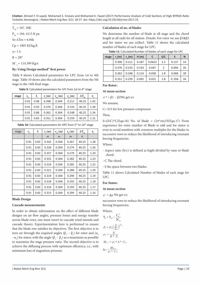
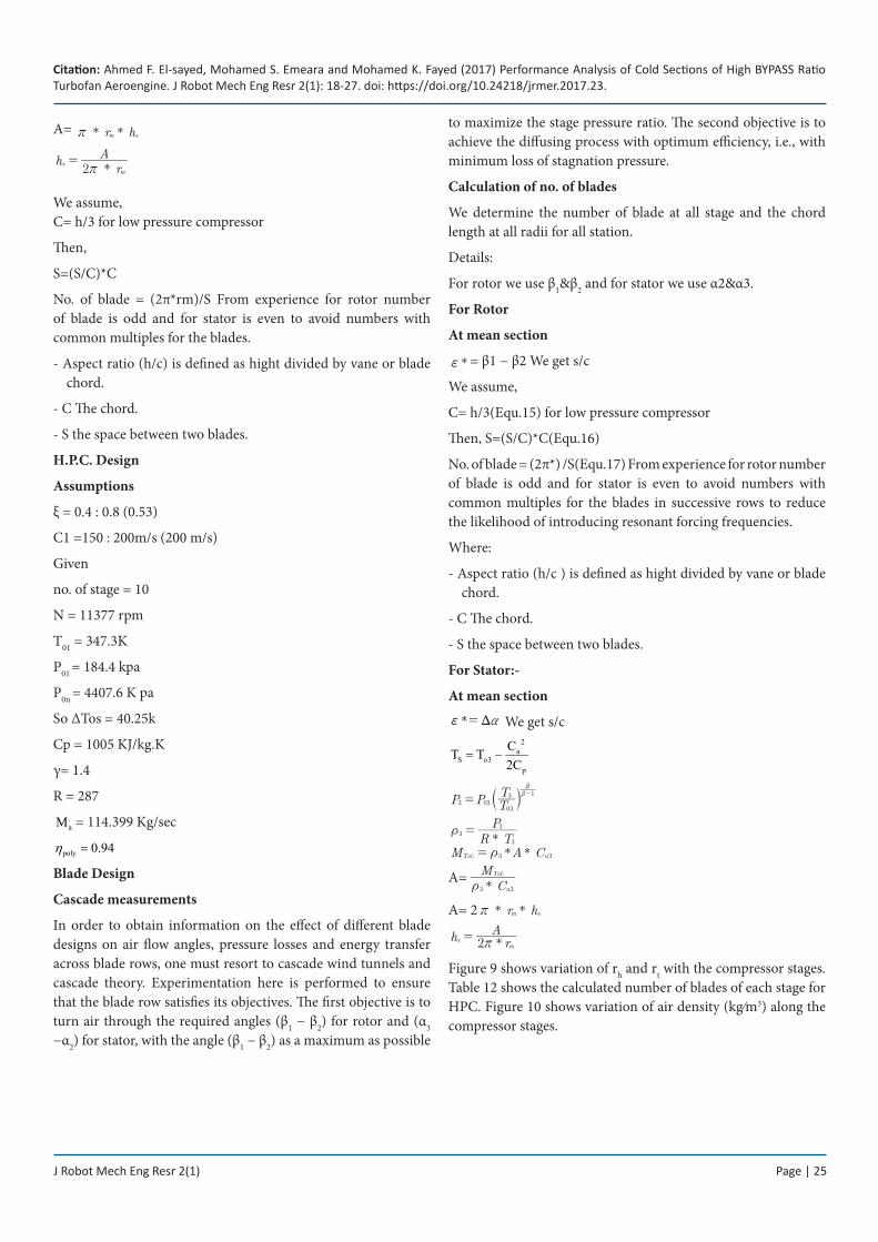
Figure 12 shows the effect of OPR on the thermal efficiency. Figure 13 shows the effect of both FPR and OPR on the overall efficiency.
Table 12: Calculated Number of blades of each stage for HPC
rt (m) rh (m) H (m) C S/C S N
0.342 0.267 0.075 0.037 1.7 0.063 30
0.336 0.274 0.062 0.031 1.7 0.053 36
0.357 0.279 0.078 0.039 1.7 0.066 29
0.331 0.282 0.049 0.024 1.7 0.041 46
0.324 0.285 0.039 0.019 1.7 0.032 60
0.321 0.288 0.033 0.016 1.7 0.027 70
0.319 0.290 0.029 0.014 1.7 0.024 79
0.318 0.292 0.026 0.013 1.7 0.022 86
0.316 0.293 0.023 0.011 1.7 0.018 106
0.315 0.294 0.021 0.010 2 0.02 95
J Robot Mech Eng Resr 2(1) Page | 27
Citation: Ahmed F. El-sayed, Mohamed S. Emeara and Mohamed K. Fayed (2017) Performance Analysis of Cold Sections of High BYPASS Ratio Turbofan Aeroengine. J Robot Mech Eng Resr 2(1): 18-27. doi: https://doi.org/10.24218/jrmer.2017.23.
Figure 12: Effect of OPR on the thermal efficiency
Figure 13: Effect of both FPR and OPR on the overall efficiency
Conclusion
The turbofan engine has a high thrust capability with low fuel consumption. From our study to the performance of one model of the turbofan engine we concluded that thrust force increases when the turbine inlet temperature increases but there is a metallurgical limitation. The thermal efficiency decreases when the overall pressure ratio of the engine increases. The specific thrust decreases when the bypass ratio increases. Finally, as the turbofan engines have many advantages, they are used the modern age in transportation and military aircrafts.
References 1. El-Sayed AF. Fundamentals of aircraft and rocket propulsion.
Springer; 2016.
2. El-Sayed AF. Aircraft propulsion and gas turbine engines. CRC Press; 2017.
3. Boyce MP. Gas turbine engineering handbook. Elsevier; 2011.
4. Saravanamuttoo HIH, Rogers GFC, Cohen H. Gas turbine theory. Pearson Education; 2001.