Review Geomechanical modeling of CO 2 geological storage: A review Pengzhi Pan a, b, * , Zhenhua Wu a, b , Xiating Feng a , Fei Yan a a State Key Laboratory of Geomechanics and Geotechnical Engineering, Institute of Rock and Soil Mechanics, Chinese Academy of Sciences, Wuhan, 430071, China b University of Chinese Academy of Sciences, Beijing, 100049, China article info Article history: Received 17 July 2016 Received in revised form 8 October 2016 Accepted 10 October 2016 Available online 27 November 2016 Keywords: Geomechanical modeling Carbon dioxide (CO 2 ) geological storage Continuum numerical method Continuumediscontinuum numerical method Fault representation Fault reactivation Fracture propagation Induced seismicity abstract This paper focuses on the progress in geomechanical modeling associated with carbon dioxide (CO 2 ) geological storage. The detailed review of some geomechanical aspects, including numerical methods, stress analysis, ground deformation, fault reactivation, induced seismicity and crack propagation, is presented. It is indicated that although all the processes involved are not fully understood, integration of all available data, such as ground survey, geological conditions, microseismicity and ground level deformation, has led to many new insights into the rock mechanical response to CO 2 injection. The review also shows that in geomechanical modeling, continuum modeling methods are predominant compared with discontinuum methods. It is recommended to develop continuumediscontinuum nu- merical methods since they are more convenient for geomechanical modeling of CO 2 geological storage, especially for fracture propagation simulation. The MohreCoulomb criterion is widely used in prediction of rock mass mechanical behavior. It would be better to use a criterion considering the effect of the intermediate principal stress on rock mechanical behavior, especially for the stability analysis of deeply seated rock engineering. Some challenges related to geomechanical modeling of CO 2 geological storage are also discussed. Ó 2016 Institute of Rock and Soil Mechanics, Chinese Academy of Sciences. Production and hosting by Elsevier B.V. This is an open access article under the CC BY-NC-ND license (http://creativecommons.org/ licenses/by-nc-nd/4.0/). 1. Introduction Greenhouse gas is regarded as one of the contributions to the global climate change, and sound ways to reduce carbon dioxide (CO 2 ) emissions have been extensively studied. Carbon capture and storage (CCS) in deep geological formations has been recognized as a promising option (Nordbotten and Celia, 2011). Such geological formations are mainly deep sedimentary formations, including oil and gas reservoirs and deep saline aquifers (Bachu, 2008; Benson and Cole, 2008; Bickle, 2009). The injection of large amounts of CO 2 into the deep subsurface may be associated with a number of geomechanical risks. Fig. 1 illustrates the main typical observations during CO 2 injection into brine aquifer (Ringrose et al., 2013). The fault or fracture zone will behave as a flow conduit for CO 2 and a focal point for rock failure. The pressure buildup inside the storage formation might lead to slip and dilation along these preexisting faults and fracture zones. Injection-induced seismicity might cause structural damage and perhaps panic among local people (Rutqvist et al., 2014). Further- more, CO 2 injection may introduce new hydraulic fractures within or near the injection zone. These fractures may propagate upwards into the lower caprock and further through the upper caprock (Ringrose et al., 2013). As a result, the shallow drinking water might be contaminated by the CO 2 leakage (Zheng et al., 2009; Apps et al., 2010; Keating et al., 2010). Concerns for geomechanical aspects associated with geological carbon storage (GCS) originated in the 1990s (Holloway and Savage, 1993; Rutqvist, 2012). Later, a series of studies, including generic modeling and actual CO 2 injection activities (e.g. In Salah CO 2 storage project in Algeria, WASP in Canada), showed that significant geomechanical changes may indeed occur, depending on the in- jection pressure and site-specific geomechanical conditions (Li et al., 2002; Rutqvist and Tsang, 2002; Streit and Hillis, 2004; Yamamoto and Takahashi, 2004; Hawkes et al., 2005; Keith and Lavoie, 2009; Rutqvist et al., 2010; Goodarzi et al., 2012; Rutqvist, 2012; Ringrose et al., 2013). In geomechanical aspects, changes in stresses and strains, ground surface deformations and potential dangers such as new caprock fracture initiation and propagation or preexisting fault opening and slippage are important for large-scale * Corresponding author. E-mail address: [email protected](P. Pan). Peer review under responsibility of Institute of Rock and Soil Mechanics, Chinese Academy of Sciences. Contents lists available at ScienceDirect Journal of Rock Mechanics and Geotechnical Engineering journal homepage: www.rockgeotech.org Journal of Rock Mechanics and Geotechnical Engineering 8 (2016) 936e947 http://dx.doi.org/10.1016/j.jrmge.2016.10.002 1674-7755 Ó 2016 Institute of Rock and Soil Mechanics, Chinese Academy of Sciences. Production and hosting by Elsevier B.V. This is an open access article under the CC BY- NC-ND license (http://creativecommons.org/licenses/by-nc-nd/4.0/).
Transcript
lable at ScienceDirect
Journal of Rock Mechanics and Geotechnical Engineering 8 (2016) 936e947
Contents lists avai
Journal of Rock Mechanics andGeotechnical Engineering
journal homepage: www.rockgeotech.org
Review
Geomechanical modeling of CO2 geological storage: A review
Pengzhi Pan a,b,*, Zhenhua Wu a,b, Xiating Feng a, Fei Yan a
a State Key Laboratory of Geomechanics and Geotechnical Engineering, Institute of Rock and Soil Mechanics, Chinese Academy of Sciences, Wuhan, 430071,ChinabUniversity of Chinese Academy of Sciences, Beijing, 100049, China
a r t i c l e i n f o
Article history:Received 17 July 2016Received in revised form8 October 2016Accepted 10 October 2016Available online 27 November 2016
* Corresponding author.E-mail address: [email protected] (P. Pan).Peer review under responsibility of Institute o
Chinese Academy of Sciences.
http://dx.doi.org/10.1016/j.jrmge.2016.10.0021674-7755 � 2016 Institute of Rock and Soil MechanicNC-ND license (http://creativecommons.org/licenses/
a b s t r a c t
This paper focuses on the progress in geomechanical modeling associated with carbon dioxide (CO2)geological storage. The detailed review of some geomechanical aspects, including numerical methods,stress analysis, ground deformation, fault reactivation, induced seismicity and crack propagation, ispresented. It is indicated that although all the processes involved are not fully understood, integration ofall available data, such as ground survey, geological conditions, microseismicity and ground leveldeformation, has led to many new insights into the rock mechanical response to CO2 injection. Thereview also shows that in geomechanical modeling, continuum modeling methods are predominantcompared with discontinuum methods. It is recommended to develop continuumediscontinuum nu-merical methods since they are more convenient for geomechanical modeling of CO2 geological storage,especially for fracture propagation simulation. The MohreCoulomb criterion is widely used in predictionof rock mass mechanical behavior. It would be better to use a criterion considering the effect of theintermediate principal stress on rock mechanical behavior, especially for the stability analysis of deeplyseated rock engineering. Some challenges related to geomechanical modeling of CO2 geological storageare also discussed.� 2016 Institute of Rock and Soil Mechanics, Chinese Academy of Sciences. Production and hosting byElsevier B.V. This is an open access article under the CC BY-NC-ND license (http://creativecommons.org/
licenses/by-nc-nd/4.0/).
1. Introduction
Greenhouse gas is regarded as one of the contributions to theglobal climate change, and sound ways to reduce carbon dioxide(CO2) emissions have been extensively studied. Carbon capture andstorage (CCS) in deep geological formations has been recognized asa promising option (Nordbotten and Celia, 2011). Such geologicalformations are mainly deep sedimentary formations, including oiland gas reservoirs and deep saline aquifers (Bachu, 2008; Bensonand Cole, 2008; Bickle, 2009).
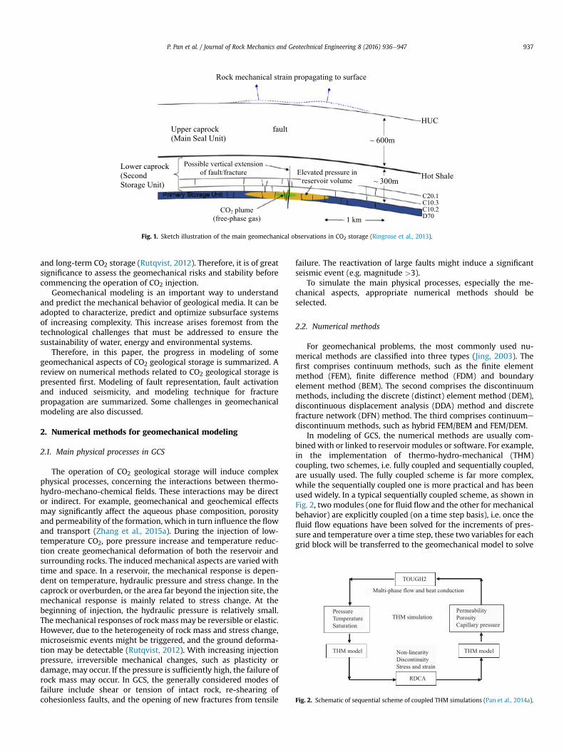
The injection of large amounts of CO2 into the deep subsurfacemay be associated with a number of geomechanical risks. Fig. 1illustrates the main typical observations during CO2 injection intobrine aquifer (Ringrose et al., 2013). The fault or fracture zone willbehave as a flow conduit for CO2 and a focal point for rock failure.The pressure buildup inside the storage formation might lead toslip and dilation along these preexisting faults and fracture zones.
f Rock and Soil Mechanics,
s, Chinese Academy of Sciences. Prby-nc-nd/4.0/).
Injection-induced seismicity might cause structural damage andperhaps panic among local people (Rutqvist et al., 2014). Further-more, CO2 injection may introduce new hydraulic fractures withinor near the injection zone. These fractures may propagate upwardsinto the lower caprock and further through the upper caprock(Ringrose et al., 2013). As a result, the shallow drinking water mightbe contaminated by the CO2 leakage (Zheng et al., 2009; Apps et al.,2010; Keating et al., 2010).
Concerns for geomechanical aspects associated with geologicalcarbon storage (GCS) originated in the 1990s (Holloway and Savage,1993; Rutqvist, 2012). Later, a series of studies, including genericmodeling and actual CO2 injection activities (e.g. In Salah CO2storage project in Algeria,WASP in Canada), showed that significantgeomechanical changes may indeed occur, depending on the in-jection pressure and site-specific geomechanical conditions (Liet al., 2002; Rutqvist and Tsang, 2002; Streit and Hillis, 2004;Yamamoto and Takahashi, 2004; Hawkes et al., 2005; Keith andLavoie, 2009; Rutqvist et al., 2010; Goodarzi et al., 2012; Rutqvist,2012; Ringrose et al., 2013). In geomechanical aspects, changes instresses and strains, ground surface deformations and potentialdangers such as new caprock fracture initiation and propagation orpreexisting fault opening and slippage are important for large-scale
oduction and hosting by Elsevier B.V. This is an open access article under the CC BY-
Possible vertical extension of fault/fracture Hot ShaleElevated pressure in
reservoir volume
CO2 plume(free-phase gas) ~ 1 km
C20.1C10.3C10.2D70
Fig. 1. Sketch illustration of the main geomechanical observations in CO2 storage (Ringrose et al., 2013).
TOUGH2
Multi-phase flow and heat conduction
THM simulation
THM modelTHM model
RDCA
PressureTemperatureSaturation
PermeabilityPorosityCapillary pressure
Non-linearityDiscontinuityStress and strain
Fig. 2. Schematic of sequential scheme of coupled THM simulations (Pan et al., 2014a).
P. Pan et al. / Journal of Rock Mechanics and Geotechnical Engineering 8 (2016) 936e947 937
and long-term CO2 storage (Rutqvist, 2012). Therefore, it is of greatsignificance to assess the geomechanical risks and stability beforecommencing the operation of CO2 injection.
Geomechanical modeling is an important way to understandand predict the mechanical behavior of geological media. It can beadopted to characterize, predict and optimize subsurface systemsof increasing complexity. This increase arises foremost from thetechnological challenges that must be addressed to ensure thesustainability of water, energy and environmental systems.
Therefore, in this paper, the progress in modeling of somegeomechanical aspects of CO2 geological storage is summarized. Areview on numerical methods related to CO2 geological storage ispresented first. Modeling of fault representation, fault activationand induced seismicity, and modeling technique for fracturepropagation are summarized. Some challenges in geomechanicalmodeling are also discussed.
2. Numerical methods for geomechanical modeling
2.1. Main physical processes in GCS
The operation of CO2 geological storage will induce complexphysical processes, concerning the interactions between thermo-hydro-mechano-chemical fields. These interactions may be director indirect. For example, geomechanical and geochemical effectsmay significantly affect the aqueous phase composition, porosityand permeability of the formation, which in turn influence the flowand transport (Zhang et al., 2015a). During the injection of low-temperature CO2, pore pressure increase and temperature reduc-tion create geomechanical deformation of both the reservoir andsurrounding rocks. The induced mechanical aspects are varied withtime and space. In a reservoir, the mechanical response is depen-dent on temperature, hydraulic pressure and stress change. In thecaprock or overburden, or the area far beyond the injection site, themechanical response is mainly related to stress change. At thebeginning of injection, the hydraulic pressure is relatively small.The mechanical responses of rockmass may be reversible or elastic.However, due to the heterogeneity of rock mass and stress change,microseismic events might be triggered, and the ground deforma-tion may be detectable (Rutqvist, 2012). With increasing injectionpressure, irreversible mechanical changes, such as plasticity ordamage, may occur. If the pressure is sufficiently high, the failure ofrock mass may occur. In GCS, the generally considered modes offailure include shear or tension of intact rock, re-shearing ofcohesionless faults, and the opening of new fractures from tensile
failure. The reactivation of large faults might induce a significantseismic event (e.g. magnitude >3).
To simulate the main physical processes, especially the me-chanical aspects, appropriate numerical methods should beselected.
2.2. Numerical methods
For geomechanical problems, the most commonly used nu-merical methods are classified into three types (Jing, 2003). Thefirst comprises continuum methods, such as the finite elementmethod (FEM), finite difference method (FDM) and boundaryelement method (BEM). The second comprises the discontinuummethods, including the discrete (distinct) element method (DEM),discontinuous displacement analysis (DDA) method and discretefracture network (DFN) method. The third comprises continuume
discontinuum methods, such as hybrid FEM/BEM and FEM/DEM.In modeling of GCS, the numerical methods are usually com-
bined with or linked to reservoir modules or software. For example,in the implementation of thermo-hydro-mechanical (THM)coupling, two schemes, i.e. fully coupled and sequentially coupled,are usually used. The fully coupled scheme is far more complex,while the sequentially coupled one is more practical and has beenused widely. In a typical sequentially coupled scheme, as shown inFig. 2, two modules (one for fluid flow and the other for mechanicalbehavior) are explicitly coupled (on a time step basis), i.e. once thefluid flow equations have been solved for the increments of pres-sure and temperature over a time step, these two variables for eachgrid block will be transferred to the geomechanical model to solve
P. Pan et al. / Journal of Rock Mechanics and Geotechnical Engineering 8 (2016) 936e947938
the solid mechanics equations for strains and to update the me-chanical states (deformation or failure). The new mechanical stateswill then be used to calculate the mechanical variable dependentpermeability modifiers for the fractured grid blocks to simulatefracture propagation for the next time step in the flow model.
The continuum-based numerical simulators, such as CODE-BRIGHT (FEM) (Olivella et al., 1994, 1996; Vilarrasa et al., 2010),FEMH (Bower and Zyvoloski, 1997; Deng et al., 2011), TOUGH-FLAC(FVM þ FDM) (Rutqvist and Tsang, 2002), OpenGeoSys (FEM)(Wang and Kolditz, 2007; Goerke et al., 2011), ECLIPSE-FE-IE(FDM þ FEM) (Ferronato et al., 2010), ECLIPSE-VISAGE(FDM þ FEM) (Ouellet et al., 2011), STARS (Bissell et al., 2011),NUFT-SYNEF (NUFT-GEODYN-L (nonlinear FEM code) (Vorobiev,2010)) (Morris et al., 2011a,b,c), DYNAFLOW (FEM) (Prevost, 1981;Preisig and Prevost, 2011), TOUGH2-Code_Aster (FEM) (Rohmerand Seyedi, 2010), AEEA Coupler (FEM þ FDM) (Fei et al., 2015),and THM-CO2 (integral FDM) (Huang et al., 2015), have beendeveloped and used to study the THM process related to GCS. Inthese numerical methods, the elastic or elastoplastic constitutiverelation is usually used to characterize the geomechanical behaviorof rocks.
The discontinuum or continuumediscontinuum based numer-ical methods are used to simulate the hydraulic fracturing of rocks.For example, Weng et al. (2011) used the displacement disconti-nuity method to develop a hydraulic fracture model to simulatecomplex-fracture-network propagation in a formation with pre-existing fractures. Fu et al. (2013) simulated hydraulic fracturepropagation in an arbitrary discrete fracture network using anexplicit coupled hydromechanical model. Torres and Castaño(2007) introduced a discrete element simulation for the hydraulicfracturing process of rocks. Dahi Taleghani (2009) presented acomplex hydraulic fracture propagation model based on extendedFEM. Damjanac et al. (2010) simulated typical hydraulic fracturingoperation in a naturally fractured rock using the DEM. Hamidi andMortazavi (2014) used 3DEC for simulating the initiation andpropagation of hydraulically induced fractures in rock mass. DePater and Beugelsdijk (2005) used DEM to handle multiple frac-ture propagation. Meyer and Bazan (2011) presented a DFN nu-merical simulator formulated for a pseudo-three-dimensional(P3D) hydraulically induced fracture system. Nasehi and Mortazavi(2013) employed a two-dimensional (2D) DEM (UDEC) to simulatethe fully coupled hydromechanical interaction between fluid flowand rock in a typical hydraulic fracturing process. Jiao et al. (2015)developed a 2D coupled hydromechanical discontinuum model forsimulating the rock hydraulic fracturing process based on DDA.Wang et al. (2016) presented a coupled bonded particle and latticeBoltzmann method for modeling hydraulic fracturing. For applica-tion of discontinuum methods to the study of GCS, relatively fewstudies have been reported. For example, the NUFT (nonisothermalunsaturatedesaturated flow and transport model) code has beenused previously in combination with the Livermore distinctelement code (Morris et al., 2006) to investigate caprock integrityduring CO2 storage (Johnson et al., 2005). Pan et al. (2012a, 2014b,c)developed a continuumediscontinuum numerical model (RDCA) tosimulate the rock fracture propagation and coalescence under fluidpressurization induced by CO2 injection.
Based on the literature review, it is found that the continuummethods are predominant in geomechanical modeling of GCScompared to discontinuum or continuumediscontinuum methods.For numerical methods, there are no absolute advantages of onemethod over another. It should be noted that the continuum-basednumerical approaches are also practically useful for simulation ofrock failure process, especially for pre-failure damage evolution.For example, the TOUGH-FLAC approach has been successfully usedin laboratory-scale studies (Lei et al., 2016) and natural analog
studies (Sorai et al., 2015). Actually, in geomechanical modeling ofGCS, the choice of numerical methods (continuum or dis-continuum) depends on problem-specific factors, such as the pur-pose of the study, problem scale and fracture geometry. Therefore,the right selection is made if the numerical method is adequate forthe representation of the mechanical behavior of rock mass.
2.3. Upscaling of geomechanical properties
The numerical modeling of geomechanical aspects of CO2geological storage, such as uplift, fault reactivation and inducedseismicity, is usually at a large scale. In some cases, it is impracticaland unnecessary to track all local behaviors of rock mass. Simpli-fication or upscaling can be used to reduce the computationalburden. In this case, appropriate model and input parametersshould be assigned to reasonably characterize the mechanicalbehavior of rock mass. The input hydromechanical properties mustbe based on the values measured by small-scale laboratory tests.However, the measured values are valid only at these small scales,representing only intact rock matrix or single small fractures.Upscaling methods should be used to transform the small-scaledata to large-scale values required as inputs to numerical models(Blum et al., 2005). However, upscaling of mechanical properties isregarded as a key and challenging issue in geomechanical modeling(Alain and Vincent, 2004; Guvanasen and Chan, 2004; Blum et al.,2005; Rodriguez et al., 2006; Ne�zerka et al., 2014; Liu et al., 2016;Zeng et al., 2016). The difficulty of upscaling lies in several as-pects. Because complete three-dimensional (3D) information aboutmechanical properties is never obtainable, numerous methodshave been developed to interpolate among data and to usegeological, hydrogeological, and geophysical information to createimages of formation properties (Koltermann and Gorelick, 1996).However, one of the challenges is that the interpolation of me-chanical parameters determined at specific locations in the rock tolocations throughout the rock may be significantly different.Furthermore, whether a representative element volume (REV) ex-ists is also a problem. Since it is dependent on the variations in thefracture density and geometry, the REV may or may not exist forfractured rocks. In addition, the presence of minor faults in caprockgreatly affects reservoir performance. These faults are usuallybelow the resolution limit of conventional 3D seismic testing.Conventional methods of fracture characterization such as one-dimensional (1D) (well logs or cores) or 2D (outcrop analogs)approach lack the spatial characterization that is needed tocomprehensively assess their impact on reservoir performance. Togain insight into the fracture characteristics of the target formation,an iterative process of modeling and incorporating production and/or injection data from field experiments may be helpful(Chiaramonte et al., 2011).
3. Modeling of ground deformation
During the injection of CO2 around the injection zone, thechanges (even small changes at the beginning) of reservoir pressurewill induce some mechanical and hydraulic responses, includingground deformation (or uplift), stress distribution and permeabilityvariation. In these responses, the estimation of ground deformationinduced by CO2 injection is important for assessing the suitability ofthe injection site. For this purpose, the analytical methods, semi-analytical methods and numerical models are often used toassess the ground deformation, stress distribution, stability andleakage of CO2. For example, Fjaer et al. (2008) proposed a simplebut practical analytical formula to calculate the reservoir verticalexpansion:
P. Pan et al. / Journal of Rock Mechanics and Geotechnical Engineering 8 (2016) 936e947 939
Dhh
¼ að1þ nÞð1� 2nÞ
ð1� nÞE DP (1)
where Dh is the vertical expansion of the reservoir, h is the thick-ness of the reservoir, a is the Biot’s coefficient, n is the Poisson’sratio, E is the Young’s modulus, and DP is the change in reservoirpressure.
The analytical solution to Eq. (1) was based on the assumptionthat the 1D reservoir is thin and laterally extensive. It does notconsider the effects of different geological formations and the re-striction of vertical expansion by overlying rock. Furthermore, theuplift in reality is not dependent on well pressure but on theaverage pressure within the injection zone. Therefore, the modelmay overestimate the ground deformation. Despite this, Rutqvist(2012) showed that the uplift obtained by Eq. (1) is in the correctorder of magnitude. To consider these effects on the uplift, semi-analytical models and numerical methods might be more useful.
For semi-analytical models, typically, Selvadurai (2009) pro-vided an elementary model of the interaction between a surfacerock layer and a deep rock mass that is pressurized during the in-jection of storage fluids. The heave (i.e. w(r)) of the surficial rocklayer due to pressures generated by injected fluids is expressed as
wðrÞ ¼ Uiath
ZN0
e�ll=h
1þ Fil3J1ðla=hÞJ0ðlr=aÞdl ði ¼ f ;bÞ (2)
where f and b are the frictionless and bonded interfaces,respectively.
Fig. 3. Contours of final vertical displacement distributions for the model with weak faultsinjection period (Zhang et al., 2015b).
The analytical and semi-analytical models for mechanical sta-bility and leakage of CO2 storage can also be found in the literature(Streit and Hillis, 2004; Lucier et al., 2006; Chiaramonte et al., 2008;Mathias et al., 2009; Selvadurai, 2009; Soltanzadeh and Hawkes,2009; Rohmer and Bouc, 2010; Vidal-Gilbert et al., 2010; Goret al., 2013; Sun et al., 2013). In some cases, these simplified models(analytical or semi-analytical) provide an effective and quickway toanalyze the mechanical behavior of rock mass. For example,Chiaramonte et al. (2011) developed a simplified, geomechanicallyconstrained 3D reservoir fluid flow simulation at Teapot Dome OilField, WY, USA, a site of a CO2 enhanced oil reservoir (CO2-EOR)sequestration pilot project. Nevertheless, to further understand thefailure mechanism or behavior of rocks in GCS, numericalmodeling, especially the associated geomechanical aspects, isrequired. Fig. 3 shows a typical numerically simulated grounddeformation using a continuum numerical method (Zhang et al.,2015b).
4. Modeling technique for faults
Geological systems are heterogeneous and discontinuous me-dia, whichmay contain faults and fractures of various sizes, i.e. fromsmall meter-scale fractures to kilometer-scale faults. Sequestrationof large amounts of CO2 within such media is a challenging tasksince the fluid pressurization may affect an area extending to aradius more than 100 km (Birkholzer and Zhou, 2009; Cappa andRutqvist, 2011a). Over such a vast area, some major faults maynot be avoidable (Cappa and Rutqvist, 2011a). Under fluid pres-surization, the faults might be reactivated and associated seismicitymay occur. CO2 migration could occur through existing fractures
and injection rates of (a) 1 Mt/yr, (b) 3 Mt/yr and (c) 5 Mt/yr at the end of a 20-year
P. Pan et al. / Journal of Rock Mechanics and Geotechnical Engineering 8 (2016) 936e947940
and fault zones. Therefore, it is important to assess the potentialrisk due to the existence of faults numerically. The fault zonesgenerally contain complex structures and a single-fault hydrome-chanical model covering all types of faults and fault stages may notbe possible. According to the scale of interest and purpose, theapproach applied to analysis of fault geomechanical behavior maybe different. For example, it is possible to represent the fault het-erogeneities in detail for small-scale simulation, while a simplifiedfault model may be represented for large-scale simulation. Forexample, in the work of Morris et al. (2011a,b,c), the faults weretreated by introducing directional weakness into the elements ofthe calculation. In the finite element analysis by Li et al. (2006), aclassical spring model was adopted to consider the mechanicalchanges of the fault. Cappa and Rutqvist (2011a) analyzed differenthydromechanical fault models and demonstrated how such modelscan be applied as part of hydromechanical analysis of a CO2 injec-tion site. Using the continuum-based TOUGH-FLAC simulator, afault or fault zone was represented by a mechanical interface orfinite-thickness solid elements with isotropic or anisotropic me-chanical behavior (Fig. 4). Their analysis showed that a finite-thickness element approach is easier to be implemented and can
Fig. 4. Representation of a fault (Cappa and Rutqvist, 2011a). (a) A zero-thicknessinterface, (b) solid elements and (c) solid elements with ubiquitous joints orientedas weak planes along the strike of fault plane.
be readily applied to different types of fault structures, from a singleslip plane to a complex fault zone.
However, difficulties can occur with the treatment of largeslopes and separations along the fault because the continuummodel paints the fault on top of the Lagrangian mesh such that itmoves with the mesh (Morris et al., 2011c). Moreover, when thereare some faults or fracture networks in the system, using the finite-thickness elemental fault representation is still a tedious task dueto the limitation of continuum numerical methods. For example, inlarge-scale GCS, the fault may be over 1 km in length and severalmeters in width. The edge length on the fault should be smallenough within the rupture area to ensure enough cells to wellresolve the weakening process. For example, Cappa and Rutqvist(2012) used an elemental size of 0.25 m for the fault in therupture zone. Using such a small elemental size to simulate a faultover 1 km in length will require many computer resources andmesh dependency may occur. To overcome these difficulties, adiscontinuum numerical method or a combination of continuumand discontinuum methods may be more convenient to representthe fault or fracture. This work has been performed by some re-searchers. For example, recently, special shape functions, i.e. theHeaviside function to simulate the crack (or fracture) surfaces, andthe asymptotic crack-tip displacement field function, have beendesigned to approximate discontinuous displacement, which isexpressed as (Stazi et al., 2003; Budyn et al., 2004):
uhðxÞ ¼Xi˛N
NiðxÞui þXmc
m¼1
Xj˛Nm
NjðxÞHmj ðxÞamj
þXmt
p¼1
Xk˛Np
NkðxÞ" X4a¼1
FpakðxÞbpak
# (3)
where N represents the total nodal number of the element; x rep-resents the coordinate; Nm is the set of nodes of the elementsintersected completely by the crack m; Np is the set of nodesassociated with crack tips in their influence domain; Ni, Nj and Nk
are the shape functions of the associated node; ui is the nodaldisplacement (standard degrees of freedom); amj is the additionalunknown for the modified step enrichment Hm
j ðxÞ of crackm; bpak isthe vector of the additional nodal degree of freedom for the tipenrichment of tip p for themodified branch function FpakðxÞ; and a isthe crack tip set.
By using the discontinuous displacement function shown in Eq.(3), with a combination of the fracture tracking method (e.g. levelset method) and partition of unity, the fracture or fault geometry isindependent of the numerical grid (Pan et al., 2012a). Therefore, afault with great length can be represented in a uniform grid and themesh dependency can be overcome. Furthermore, arbitrary frac-ture geometry (e.g. curved fracture) can be conveniently simulated.Fig. 5 shows the case of a zigzag caprock fracture geometry, throughsimply updating the discontinuity geometry (Pan et al., 2014a),demonstrating the versatility of this method.
5. Modeling of fault activation and induced seismicity
5.1. Fault activation
The possible activation of a preexisting fault may occur when-ever the shear stress acting on the fracture plane exceeds theMohreCoulomb failure criterion (Wiprut and Zoback, 2000; Jaegeret al., 2007):
jssj � cþ s0ntanf (4)
Fig. 5. The fracture mechanical behavior during injection of CO2 (�1000). (a) 12 months, (b) 15 months, (c) 18 months and (d) 36 months (Pan et al., 2014a).
P. Pan et al. / Journal of Rock Mechanics and Geotechnical Engineering 8 (2016) 936e947 941
where s0n and ss are the normal and shear stresses, respectively; c isthe cohesion; f is the friction angle; and tanf represents the staticfriction coefficient. s0n is positive when the fault is in compression.s0n represents the effective normal stress on the fault, which isreduced by an increase in pore pressure or by a reduction in the insitu confining stress. The fault can slip when jssj is greater than orequal to the right-hand side of Eq. (4) (Fig. 6). The fault may openwhen the tensile stress is applied.
In practice, given that no direct measurements of c can be usedin Eq. (4), the contribution of fault cohesion to shear strength isusually neglected (i.e. c ¼ 0 MPa or a small value) (Ferronato et al.,2010; Cappa and Rutqvist, 2011a). In most of the generic modelingstudies, a slip-weakening modeling is used. In this case, the frictioncoefficient drops from a peak value to a residual value to model therupture of the fault. Although the peak friction coefficient (i.e. tanf)is typically in the range of 0.6e0.85 (with the friction angle of about30�e39�) (Goodman, 1975; Byerlee, 1978; Vidal-Gilbert et al.,2009), many researchers used a lower value of peak friction coef-ficient (e.g. 0.47, corresponding to the friction angle of 25�, or evenlower friction angle of 14�) (Streit and Hillis, 2004; Cappa andRutqvist, 2011c; Pereira et al., 2014; Figueiredo et al., 2015; Weiet al., 2016a). A residual friction coefficient of 0.2 (i.e. a frictionangle of approximately 11�) is often used (Cappa and Rutqvist,2012). It should be noted that the friction coefficients of faults aredependent on several factors, such as temperature, degree ofsaturation and the constituents of the fault content (Saffer andMarone, 2003). Experimental studies indicate that the friction co-efficient of pure smectite under the vacuum-dried condition is 0.3e0.4, while it would be 0.13e0.3 under the saturated condition(Morrow et al., 1992, 2000). The friction coefficient of smectite-quartz mixtures is approximately 0.2e0.53, while it is muchhigher for illite shale (0.41e0.73) (Saffer and Marone, 2003).Therefore, these factors should be considered in the selection of thefriction coefficient.
The MohreCoulomb failure criterion in Eq. (4) or its modifica-tion is practically useful for describing the slip tendency. In theanalysis, the stress is an important factor to be considered in theevaluation of fault activation or slip tendency. In most studies, theslip tendency is calculated based on the pre-injection principalstress magnitude and orientation corresponding to the regionalstress field. However, studies show that in situ stress state can bechanged because of poro-elastic stress development related to thechanges in pore pressure and temperature (Kano et al., 2014).Therefore, it is necessary to assess the impact of stress uncertaintyinduced by CO2 injection on fault stability.
In most recent studies, fault reactivation is treated as a quasi-static mechanical process (Cappa and Rutqvist, 2011a,b,c). In adynamic simulation of fault slip induced by CO2 injection, rate- andstate-dependent friction laws should be involved. In this case,friction is assumed to evolve from the static value to a referencedynamic value linearly with increasing slip displacement, until thecritical distance is reached. Thereafter, the friction coefficient de-pends on sliding velocity, according to the rate- and state-dependent friction law (Urpi et al., 2016). This law can be inter-preted from laboratory experiments in the conceptual model of therate- and state-dependent friction laws (Scholz, 1998; Niemeijeret al., 2012). In this case, the reliability of laboratory data, whenextrapolated to faults in nature, especially in terms of upscaling theresults from laboratory to field data, should be evaluated.
5.2. Induced microseismicity
In large-scale storage of CO2 in deep underground reservoirs,concern has been focused on whether nearby faults could bereactivated since fault reactivation might be accompanied by aseismic event. Many relevant modeling studies have been con-ducted (e.g. Lucier et al., 2006; Bissell et al., 2011; Lei et al., 2013;Atkinson et al., 2016) and the analyses show great uncertainties
Fig. 6. (a) Normal and shear stresses resolved on a fault with a given orientation from the remote principal stresses and pressure in fault by fluid injection; (b) Mohr diagram ofshear stress versus effective normal stress showing how the increasing fluid pressure may activate a fault.
P. Pan et al. / Journal of Rock Mechanics and Geotechnical Engineering 8 (2016) 936e947942
in the in situ stress and the assumed strength properties. In GCS,tensile and shear failure occurs as a consequence of the injectionand the common criterion to decide that failure is based on acritical fluid pressure for fracturing that exceeds a given tectonicstress (Rutqvist et al., 2008; Stanchits et al., 2011). To use this cri-terion, an accurate estimation of in situ stress field is essential(Rutqvist et al., 2008). However, Carcione et al. (2015) found that itis easier to establish the failure criterion on the basis of the strengthof the rock, since this information (stiffness modulus) can be ob-tained from seismic data. Langenbruch and Shapiro (2014) showedthat the elastic heterogeneity of rocks obtained from sonic anddensity logs along boreholes causes significant fluctuations offracture reactivation and opening pressures. The stiffness moduluscan be obtained from seismic and sonic-log data or ultrasonic ex-periments on cores. Other criteria exist to determine the emission,for instance, Rozhko (2010) used the effective-stress law and theCoulomb yielding stress obtained from geomechanical triaxiallaboratory measurements. Carcione et al. (2015) introduced arealistic forward modeling algorithm to simulate P- and S-wave
Fig. 7. Earthquake scaling relationship after Viegas et al. (2010): source dimension (radius) anand Rutqvist (2011b).
propagation, where each source strength and radiation pattern aredetermined by the pore pressure and a generalized moment-tensortheory, respectively.
As mentioned above, if the MohreCoulomb failure criterion isused, the fault will reactivate when jssj is greater than or equal tothe right-hand side of Eq. (4). The microseismicity or earthquakeinduced by fault reactivation is mathematically modeled by a sheardisplacement discontinuity (dislocation) across a surface S in anelastic medium. This dislocation is equivalent to a distribution ofdouble couples on this surface whose total moment (i.e. seismicmoment) M0 is (Kanamori and Anderson, 1975)
M0 ¼ mAd (5)
where m is the shear modulus of the fault media (Pa), A is therupture area of S (m2), and d is the average dislocation or slip (m).
Fig. 7 shows the typical simulation results of seismic moment byCappa and Rutqvist (2011b). The seismological theories are used tocalculate the magnitude (M) of microseismicity:
d seismic moment. Red and black circles correspond to the simulation results by Cappa
P. Pan et al. / Journal of Rock Mechanics and Geotechnical Engineering 8 (2016) 936e947 943
M ¼ log10M0=1:5� 6:1 (6)
In the modeling, the magnitude of microseismicity depends onthe constitutive law for the fault. A brittle fault with a peak and aresidual friction coefficient may produce an earthquake largeenough to be felt by humans.
Regarding the microseismicity propagation patterns, sinceplastic strain occurs when a seism occurs, the regionwhere seismicevents would occur can be assessed by tracking the evolution ofplastic strain, which can be obtained by using an elastoplasticconstitutive law or elasto-viscoplastic constitutive law (Vilarrasaet al., 2010, 2013).
Fault reactivation may be accompanied by seismicity asmentioned above. However, it may also be aseismic. Therefore, anadvanced technique should be developed to detect the aseismicfault slip since it will result in leakage quietly and should be paidmore attention.
6. Modeling technique for fracture propagation
As mentioned above, the caprock may be discontinuous andmay contain heterogeneities such as faults and fractures of varioussizes, i.e. from small meter-scale fractures to kilometer-scale faults.One of themost important concernswith respect to the safe storageof CO2 is that the formation fracturing could potentially providepathways for CO2 leakage through previously impermeable rocks. Itis important to model fracture propagation for several reasons(Goodarzi et al., 2012): (1) to avoid fracture propagation throughthe caprock to the extent that it would create a loss of containment(i.e. connect to other permeable zones) by controlling the injectionrate, (2) to use the information on fracture length to correctlydesign the well pattern, and (3) to be able to control the injectionrate to avoid excessive fracture lengths.
However, because of the complexity of rock formations, analysisof rock fracture propagation is one of the challenges in computa-tional rock mechanics.
Over the past few decades, several approaches have been pro-posed to model crack problems (Abdelaziz and Hamouine, 2008):the method based on quarter-point finite element (Henshell andShaw, 1975), enriched FEM (Benzley, 1974; Gifford and Hilton,1978), the boundary collocation method (Newman, 1971), the in-tegral equation method, the body force method (Nisitani, 1985),BEM (Cruse, 1988), the dislocation method (Vitek, 1977), and mesh-freemethods such as the element-free Galerkinmethod (Belytschkoet al., 1994). To avoid the remeshing step in crack modeling, severaltechniques have been proposed: the incorporation of a discontin-uousmodel on an element level (Oliver et al., 2002), a moving meshtechnique (Rashid, 1998), and an enrichment technique based on apartition of unity XFEM (Belytschko and Black, 1999).
For determination of crack propagation, two sets of criteria, i.e.toughness-based fracturing criterion and MohreCoulomb criterionwith tension cutoff, have been commonly used to simulate thefracturing behavior of rocks. The toughness-based fracturing crite-rion is typically employed in small-scale fracture propagation(Adachi et al., 2007). For large-scale simulation (e.g. CO2 injectioninto brine aquifer), the MohreCoulomb criterionwith tension cutoffis often used to determine the condition of fracture propagation.This criterion uses well-known parameters: tensile strength, frictionangle, cohesion and dilation angle (Zhang et al., 2015b).
For the modeling of fracturing induced by CO2 injection, only afew publications can be found in the literature. For example, Ji et al.(2009) presented a fracturing model that couples a 3D finiteelement geomechanical model with a conventional 3D finite dif-ference reservoir simulator. Compared to the continuum numerical
methods, the discontinuum method may be more convenient tosimulate the propagation of a single fracture, multiple fractures andeven the fracture networks. For example, Pan et al. (2014a) devel-oped a TOUGH-RDCA simulator for modeling rock discontinuousmechanical behavior under multiphase fluid flow conditions. Inthis simulator, the fracture geometry is independent of the nu-merical grid so that no remeshing is needed during the propagationof rock fractures, which is essentially different from continuumnumerical methods and therefore greatly simplifies the simulationof fracture propagation. The TOUGH-RDCA simulator was used tostudy the propagation of single and multiple fractures in caprockduring CO2 injection into a deep brine aquifer (Pan et al., 2013,2014b). The initiation, propagation and coalescence of fractures incaprock and the CO2 migration can be simulated explicitly by usingthis method (Figs. 8 and 9) (Pan et al., 2014b).
It should be noted that the rock mass mechanical changesinduced by CO2 injection are gradual. Before cracking, the rock canbe regarded as a continuous formation, which means thatdisplacement continuity is maintained. After cracking, the rock canbe considered as a discontinuous medium since displacementdiscontinuity occurs. Therefore, the challenge is how to find nu-merical methods to describe the rock fracturing process fromcontinuity to discontinuity. The continuum damage mechanics andfracture mechanics are usually used to describe the continuity anddiscontinuity parts, respectively. However, the link between thesetwo approaches suffers from several difficulties: energetic equiva-lence, initial crack shape and size definition. The application ofdamage-based propagation in the XFEM framework is a possibleway to address this problem (Minnebo et al., 2011).
Although productive work has been obtained in the modeling ofthe rock fracturing problem, the modeling of 3D fracturing is still achallenge. There are only a few papers concerned about the 3Dimplementation of such methods. One of the difficult issues in a 3Dsetting is how to describe and track the crack surface (Rabczuket al., 2010). In this case, the difficulties in the analysis of 3D frac-ture problems by the standard FEM lie in (1) the need to construct amesh that conforms to both the crack surface and the body ge-ometry, (2) the need to refine the mesh around the crack front, and(3) the need to remesh at each growth step in crack propagationstudies. By using the enrichment functions, which are realizedthrough the partition of unity concept, the mesh does not need toconform to the crack boundaries. The 3D curved cracks can betracked by using the level set method (González-Albuixech et al.,2013).
7. Discussion and conclusions
In this paper, we presented a review on the geomechanicalmodeling of CO2 geological storage, emphasizing on numericalmethods, representation of a fault, fault activation and fracturepropagation. Based on this work, some possible challenges andrecommendations in geomechanical modeling are listed below:
(1) Rock mass is significantly heterogeneous. It usually containscomplex combinations of constituents. With the long historyof formation, various geological media are ubiquitous, whichmakes rock masses a difficult material for mathematicalrepresentation via numerical modeling. For example, atypical CO2 storage reservoir usually contains differentgeological groups (e.g. lower aquifer, caprock rock and upperaquifer), faults and cracks, etc. In numerical modeling, aconvenient way to represent the interfaces between differentmaterial domains is still a challenge. Under mechanicalloading, the interface may behave strain continuity (weakdiscontinuity) initially and then displacement discontinuity
Fig. 8. Fracturing of F1 and connections to F2 in caprock during CO2 injection (Pan et al., 2014b).
Fig. 9. CO2 saturation evolution during injection (Pan et al., 2014b) (X and Z in m).
P. Pan et al. / Journal of Rock Mechanics and Geotechnical Engineering 8 (2016) 936e947944
(strong discontinuity) may occur. One possible solution is touse an enrichment function in displacement approximationthrough the concept of partition of unity. The interfaces canbe located by level set method (Sukumar et al., 2001). Bydoing so, the modeling of large-scale CO2 storage in complexgeological conditions would be greatly simplified.
(2) It is recognized that CO2 injectionmay stimulate or reactivatenatural fractures and may introduce new hydraulic fractureswithin or near the injection zone. These fractures maypropagate upwards into the lower caprock and furtherthrough the upper caprock (Ringrose et al., 2013). For theinitiation of fracture or crack in caprock, Rutqvist et al. (2002)used the pressure margin to assess the possible fracturingregion. This is an elastic analysis and provides a quick way toevaluate the approximate fracturing zone. Using thismethod, the fracturing zone may be smaller than that usingan elastoplastic analysis, since the plasticity-induced stress
adjustment will lead to further failure of rock mass. There-fore, it is recommended to consider the whole failure processof rock mass in geomechanical modeling of GCS. The frac-turing of rock mass is actually a continuousediscontinuousprocess, which generally experiences elastic deformation,plastic deformation or damage, fracture initiation, fracturepropagation and coalescence. A numerical method to char-acterize this continuousediscontinuous deformation failureprocess induced by CO2 injection is needed.
(3) CO2 is usually injected into subsurface media with greatdepth, where the stress environment is much more complexthan that in near-surface rock engineering. Therefore, any ofthe three mutually perpendicular principal stress compo-nents in 3D stress space should not be neglected in themodeling. Rockwill exhibit different failure conditions underdifferent stress paths. In previous studies, the MohreCoulomb criterion, which neglects the effect of the
P. Pan et al. / Journal of Rock Mechanics and Geotechnical Engineering 8 (2016) 936e947 945
intermediate principal stress, is widely used to determinewhether the rock mass yields or not. However, many studieshave shown that both the intermediate and minimumprincipal stresses greatly affect the mechanical behavior ofrock mass (Mogi, 2007; Pan et al., 2012b,c). Therefore, in theassessment of rock mass stability in GCS, a yield criterionconsidering both the intermediate and minimum principalstresses is recommended.
(4) Although the induced seismicity has been extensively stud-ied by researchers, challenges in assessing the inducedseismicity risk in CO2 storage still exist. Due to geophysicalcharacterization and monitoring limitations, there are verylarge uncertainties in the inputs of the modeling (White andFoxall, 2016). Therefore, novel strategies are necessary forreducing and/or circumventing these uncertainties (Weiet al., 2016b).
(5) A true geomechanical model for CO2 storage requires com-plete knowledge of the geometrical and physical propertiesand parameters of the fractured rock masses. In other words,if the modeling is to incorporate the main components of therock realitydthe fractures, inhomogeneity, anisotropy andinelasticity, including failureda more extensive model and amore extensive rock mass characterization are required.However, the great uncertainties of geological conditions inGCS make this complete knowledge impossible. Thus, thechallenge is to know how to develop an adequatemodel. Thiswill rest on a scientific foundation and require empiricaljudgments supported by accumulated experiences throughlong-term practices (Jing, 2003).
The above issues or challenges cannot cover all points of diffi-culty in geomechanical modeling in GCS. Other issues, such as thelarge-scale computational capacity, the scale and time effects, long-term behavior of rock mass, the evaluation of geological and en-gineering uncertainties, and the determination of in situ stress, arealso the major concerns and should be further studied for the long-term storage of CO2.
Conflict of interest
The authors wish to confirm that there are no known conflicts ofinterest associated with this publication and there has been nosignificant financial support for this work that could have influ-enced its outcome.
Acknowledgements
This work was finically supported by the National Natural Sci-ence Foundation of China (Grant Nos. 41272349 and 51322906) andKey Research Program of Frontier Sciences, Chinese Academy ofSciences (Grant No. QYZDB-SSW-DQC029).
References
Abdelaziz Y, Hamouine A. A survey of the extended finite element. Computers &Structures 2008;86(11e12):1141e51.
Adachi J, Siebrits E, Peirce A, Desroches J. Computer simulation of hydraulic frac-tures. International Journal of Rock Mechanics and Mining Sciences 2007;44(5):739e57.
Alain T, Vincent R. Hydro-mechanical upscaling of a fractured rockmass using a 3Dnumerical approach. In: Stephanson O, editor. Elsevier Geo-Engineering BookSeries, vol. 2. Elsevier; 2004. p. 275e80.
Apps JA, Zheng L, Zhang Y, Xu T, Birkholzer JT. Evaluation of potential changes ingroundwater quality in response to CO2 leakage from deep geologic storage.Transport in Porous Media 2010;82(1):215e46.
Atkinson GM, Eaton DW, Ghofrani H, Walker D, Cheadle B, Schultz R,Shcherbakov R, Tiampo K, Gu J, Harrington RM, Liu Y, van der Baan M, Kao H.Hydraulic fracturing and seismicity in the western Canada sedimentary basin.
Seismological Research Letters 2016;87(5). http://dx.doi.org/10.1785/0220150263.
Bachu S. CO2 storage in geological media: role, means, status and barriers todeployment. Progress in Energy and Combustion Science 2008;34(2):254e73.
Belytschko T, Black T. Elastic crack growth in finite elements with minimalremeshing. International Journal for Numerical Methods in Engineering1999;45(5):601e20.
Belytschko T, Lu YY, Gu L. Element free Galerkin methods. International Journal forNumerical Methods in Engineering 1994;37(2):229e56.
Benson SM, Cole DR. CO2 sequestration in deep sedimentary formations. Elements2008;4(5):325e31.
Benzley SE. Representation of singularities with isoparametric finite elements. In-ternational Journal for Numerical Methods in Engineering 1974;8(3):537e45.
Bickle MJ. Geological carbon storage. Nature Geoscience 2009;2(12):815e8.Birkholzer JT, Zhou Q. Basin-scale hydrogeologic impacts of CO2 storage: capacity
and regulatory implications. International Journal of Greenhouse Gas Control2009;3(6):745e56.
Bissell RC, Vasco DW, Atbi M, Hamdani M, Okwelegbe M, Goldwater MH. A full fieldsimulation of the In Salah gas production and CO2 storage project using acoupled geo-mechanical and thermal fluid flow simulator. Energy Procedia2011;4:3290e7.
Blum P, Mackay R, Riley MS, Knight JL. Performance assessment of a nuclear wasterepository: upscaling coupled hydro-mechanical properties for far-field trans-port analysis. International Journal of Rock Mechanics and Mining Sciences2005;42(5e6):781e92.
Bower KM, Zyvoloski G. A numerical model for thermo-hydro-mechanical couplingin fractured rock. International Journal of Rock Mechanics and Mining Sciences1997;34(8):1201e11.
Budyn E, Zi G, Moës N, Belytschko T. A method for multiple crack growth in brittlematerials without remeshing. International Journal for Numerical Methods inEngineering 2004;61(10):1741e70.
Byerlee J. Friction of rocks. Pure and Applied Geophysics 1978;116(4e5):615e26.Cappa F, Rutqvist J. Impact of CO2 geological sequestration on the nucleation of
earthquakes. Geophysical Research Letters 2011b;38(17). http://dx.doi.org/10.1029/2011GL048487.
Cappa F, Rutqvist J. Impact of CO2 geological sequestration on the nucleation ofseismic fault ruptures. In: Proceedings of the 45th US Rock Mechanics/Geo-mechanics Symposium. American Rock Mechanics Association; 2011c.
Cappa F, Rutqvist J. Modeling of coupled deformation and permeability evolutionduring fault reactivation induced by deep underground injection of CO2. In-ternational Journal of Greenhouse Gas Control 2011a;5(2):336e46.
Cappa F, Rutqvist J. Seismic rupture and ground accelerations induced by CO2 injectionin the shallow crust. Geophysical Journal International 2012;190(3):1784e9.
Carcione JM, Da Col F, Currenti G, Cantucci B. Modeling techniques to study CO2-injection induced micro-seismicity. International Journal of Greenhouse GasControl 2015;42:246e57.
Chiaramonte L, Zoback M, Friedmann J, Stamp V, Zahm C. Fracture characterizationand fluid flow simulation with geomechanical constraints for a CO2eEOR andsequestration project Teapot Dome Oil Field, Wyoming, USA. Energy Procedia2011;4:3973e80.
Chiaramonte L, Zoback MD, Friedmann J, Stamp V. Seal integrity and feasibility ofCO2 sequestration in the Teapot Dome EOR pilot: geomechanical site charac-terization. Environmental Geology 2008;54(8):1667e75.
Cruse TA. Boundary element analysis in computational fracture mechanics.Springer; 1988.
Dahi Taleghani A. Analysis of hydraulic fracture propagation in fractured reservoirs:an improved model for the interaction between induced and natural fractures.PhD Thesis. The University of Texas at Austin; 2009.
Damjanac B, Gil I, Pierce M, Sanchez M, Van As A, McLennan J. A new approach tohydraulic fracturing modeling in naturally fractured reservoirs. In: The 44th USRock Mechanics Symposium and 5th US-Canada Rock Mechanics Symposium.American Rock Mechanics Association; 2010.
De Pater CJ, Beugelsdijk LJL. Experiments and numerical simulation of hydraulicfracturing in naturally fractured rock. In: Alaska Rocks 2005, the 40th USSymposium on Rock Mechanics (USRMS). American Rock Mechanics Associa-tion; 2005.
Deng H, Dai Z, Jiao Z, Stauffer PH, Surdam RC. Simulation of CO2 sequestrationat Rock Spring uplift, Wyoming: heterogeneity and uncertainties in storagecapacity, injectivity and leakage. Los Alamos National Laboratory (LANL);2011.
Fei WB, Li Q, Wei XC, Song RR, Jing M, Li XC. Interaction analysis for CO2 geologicalstorage and underground coal mining in Ordos Basin, China. Engineering Ge-ology 2015;196:194e209.
Ferronato M, Gambolati G, Janna C, Teatini P. Geomechanical issues of anthropo-genic CO2 sequestration in exploited gas fields. Energy Conversion and Man-agement 2010;51(10):1918e28.
Figueiredo B, Tsang CF, Rutqvist J, Bensabat J, Niemi A. Coupled hydro-mechanicalprocesses and fault reactivation induced by CO2 Injection in a three-layerstorage formation. International Journal of Greenhouse Gas Control 2015;39:432e48.
Fjaer E, Holt RM, Horsrud P, Raaen AM, Risnes R. Petroleum related rock mechanics.2nd ed. Elsevier; 2008.
Fu P, Johnson SM, Carrigan CR. An explicitly coupled hydro-geomechanical modelfor simulating hydraulic fracturing in arbitrary discrete fracture networks.
P. Pan et al. / Journal of Rock Mechanics and Geotechnical Engineering 8 (2016) 936e947946
International Journal for Numerical and Analytical Methods in Geomechanics2013;37(14):2278e300.
Gifford LN, Hilton P. Stress intensity factors by enriched finite elements. EngineeringFracture Mechanics 1978;10(3):485e96.
Goerke UJ, Park CH, Wang W, Singh AK, Kolditz O. Numerical simulation of multi-phase hydromechanical processes induced by CO2 injection into deep salineaquifers. Oil & Gas Science and Technology e Revue d’IFP Energies nouvelles2011;66(1):105e18.
González-Albuixech VF, Giner E, Tarancón JE, Fuenmayor FJ, Gravouil A. Domainintegral formulation for 3D curved and non-planar cracks with the extendedfinite element method. Computer Methods in Applied Mechanics and Engi-neering 2013;264:129e44.
Goodarzi S, Settari A, Keith D. Geomechanical modeling for CO2 storage in Niskuaquifer in Wabamun Lake area in Canada. International Journal of GreenhouseGas Control 2012;10:113e22.
Goodman RE. Methods of geological engineering in rock discontinuities. St. Paul:West Publishers; 1975.
Gor GY, Stone HA, Prévost JH. Fracture propagation driven by fluid outflow from alow-permeability aquifer. Transport in Porous Media 2013;100(1):69e82.
Guvanasen V, Chan T. Upscaling the thermohydromechanical properties of a frac-tured rock mass using a modified crack tensor theory. In: Stephanson O, editor.Elsevier Geo-Engineering Book Series, vol. 2. Elsevier; 2004. p. 251e6.
Hamidi F, Mortazavi A. A new three dimensional approach to numerically modelhydraulic fracturing process. Journal of Petroleum Science and Engineering2014;124:451e67.
Hawkes CD, McLellan P, Bachu S. Geomechanical factors affecting geological storageof CO2 in depleted oil and gas reservoirs. Journal of Canadian PetroleumTechnology 2005;44(10):52e61.
Henshell RD, Shaw KG. Crack tip finite elements are unnecessary. InternationalJournal for Numerical Methods in Engineering 1975;9(3):495e507.
Holloway S, Savage D. The potential for aquifer disposal of carbon dioxide in the UK.Energy Conversion and Management 1993;34(9e11):925e32.
Huang ZQ, Winterfeld PH, Xiong Y, Wu YS, Yao J. Parallel simulation of fully-coupledthermal-hydro-mechanical processes in CO2 leakage through fluid-drivenfracture zones. International Journal of Greenhouse Gas Control 2015;34:39e51.
Jaeger JC, Cook NGW, Zimmerman RW. Fundamentals of rock mechanics. 4th ed.Oxford, UK: Wiley-Blackwell; 2007.
Ji L, Settari A, Sullivan RB. A novel hydraulic fracturing model fully coupled withgeomechanics and reservoir simulation. SPE Journal 2009;14(3):423e30.
Jiao YY, Zhang HQ, Zhang XL, Li HB, Jiang QH. A two-dimensional coupled hydro-mechanical discontinuum model for simulating rock hydraulic fracturing. In-ternational Journal for Numerical and Analytical Methods in Geomechanics2015;39(5):457e81.
Jing L. A review of techniques, advances and outstanding issues in numericalmodelling for rock mechanics and rock engineering. International Journal ofRock Mechanics and Mining Sciences 2003;40(3):283e353.
Johnson JW, Nitao JJ, Morris JP. Reactive transport modeling of cap-rock integrityduring natural and engineered CO2 storage. In: Thomas DC, editor. Carbon di-oxide capture for storage in deep geologic formations, vol. 2. Amsterdam:Elsevier; 2005. p. 787e813.
Kanamori H, Anderson DL. Theoretical basis of some empirical relations in seis-mology. Bulletin of the Seismological Society of America 1975;65(5):1073e95.
Kano Y, Funatsu T, Nakao S, Kusunose K, Ishido T, Lei X, Tosha T. Analysis of changesin stress state and fault stability related to planned CO2 injection at the Tom-akomai offshore site. Energy Procedia 2014;63:2870e8.
Keating EH, Fessenden J, Kanjorski N, Koning DJ, Pawar R. The impact of CO2 onshallow groundwater chemistry: observations at a natural analog site and im-plications for carbon sequestration. Environmental Earth Sciences 2010;60(3):521e36.
Keith D, Lavoie R. An overview of the Wabamun area CO2 sequestration project(WASP). Energy Procedia 2009;1(1):2817e24.
Koltermann CE, Gorelick SM. Heterogeneity in sedimentary deposits: a review ofstructure-imitating, process-imitating, and descriptive approaches. Water Re-sources Research 1996;32(9):2617e58.
Langenbruch C, Shapiro S. Gutenberg-Richter relation originates from Coulombstress fluctuations caused by elastic rock heterogeneity. Journal of GeophysicalResearch: Solid Earth 2014;119(2):1220e34.
Lei X, Funatsu T, Ma S, Liu L. A laboratory acoustic emission experiment and nu-merical simulation of rock fracture driven by a high-pressure fluid source.Journal of Rock Mechanics and Geotechnical Engineering 2016;8(1):27e34.
Lei X, Ma S, Chen W, Pang C, Zeng J, Jiang B. A detailed view of the injection-inducedseismicity in a natural gas reservoir in Zigong, southwestern Sichuan Basin,China. Journal of Geophysical Research: Solid Earth 2013;118(8):4296e311.
Li Q, Wu Z, Bai Y, Yin X, Li X. Thermo-hydro-mechanical modeling of CO2 seques-tration system around fault environment. Pure and Applied Geophysics2006;163(11):2585e93.
Li Q, Wu Z, Li X, Ohsumi T, Koide H. Numerical simulation on crust deformation dueto CO2 sequestration in deep aquifers. Journal of Applied Mechanics 2002;5:591e600.
Liu J, Pereira GG, Liu Q, Regenauer-Lieb K. Computational challenges in the analysesof petrophysics using microtomography and upscaling: a review. Computers &Geosciences 2016;89:107e17.
Lucier A, Zoback M, Gupta N, Ramakrishnan T. Geomechanical aspects of CO2sequestration in a deep saline reservoir in the Ohio River Valley region. Envi-ronmental Geosciences 2006;13(2):85e103.
Mathias SA, Hardisty PE, Trudell MR, Zimmerman RW. Screening and selection ofsites for CO2 sequestration based on pressure buildup. International Journal ofGreenhouse Gas Control 2009;3(5):577e85.
Meyer BR, Bazan LW. A discrete fracture network model for hydraulically inducedfractures-theory, parametric and case studies. In: SPE Hydraulic FracturingTechnology Conference. Society of Petroleum Engineers; 2011.
Minnebo H, Van Hoof T, Lani F. Damage to fracture in 3D with XFEM. In: The 5thInternational Conference on Advanced Computational Methods in Engineering(ACOMEN 2011). University of Liège; 2011.
Mogi K. Experimental rock mechanics. London: Taylor & Francis/A.A.Balkema; 2007.Morris JP, Hao Y, Foxall W, McNab W. In Salah CO2 storage JIP: hydromechanical
simulations of surface uplift due to CO2 injection at In Salah. Energy Procedia2011a;4:3269e75.
Morris JP, Detwiler RL, Friedmann SJ, Vorobiev OY, Hao Y. The large-scale geo-mechanical and hydrogeological effects of multiple CO2 injection sites on for-mation stability. International Journal of Greenhouse Gas Control 2011b;5(1):69e74.
Morris JP, Hao Y, Foxall W, McNab W. A study of injection-induced mechanicaldeformation at the In Salah CO2 storage project. International Journal ofGreenhouse Gas Control 2011c;5(2):270e80.
Morris JP, Rubin MB, Block GI, Bonner MP. Simulations of fracture and fragmenta-tion of geologic materials using combined FEM/DEM analysis. InternationalJournal of Impact Engineering 2006;33:463e73.
Morrow CA, Moore DE, Lockner DA. The effect of mineral bond strength andadsorbed water on fault gouge frictional strength. Geophysical Research Letters2000;27(6):815e8.
Morrow CA, Radney B, Byerlee J. Frictional strength and the effective pressure law ofmontmorillonite and illite clays. International Geophysics 1992;51:69e88.
Nasehi MJ, Mortazavi A. Effects of in-situ stress regime and intact rock strengthparameters on the hydraulic fracturing. Journal of Petroleum Science and En-gineering 2013;108:211e21.
Newman JC. An improved method of collocation for the stress analysis of crackedplates with various shaped boundaries. Washington, D.C.: National Aeronauticsand Space Administration; 1971.
Ne�zerka V, Slí�zková Z, Tesárek P, Plachý T, Frankeová D, Petrá�nová V. Comprehen-sive study on mechanical properties of lime-based pastes with additions ofmetakaolin and brick dust. Cement and Concrete Research 2014;64:17e29.
Niemeijer A, Di Toro G, Griffith WA, Bistacchi A, Smith SAF, Nielsen S. Inferringearthquake physics and chemistry using an integrated field and laboratoryapproach. Journal of Structural Geology 2012;39:2e36.
Nisitani H. Body force method for determination of stress intensity factors. Journalof Aerospace Sciences and Technologies 1985;37:21e41.
Nordbotten JM, Celia MA. Geological storage of CO2: modeling approaches for large-scale simulation. John Wiley & Sons; 2011.
Olivella S, Carrera J, Gens A, Alonso EE. Nonisothermal multiphase flow of brine andgas through saline media. Transport in Porous Media 1994;15(3):271e93.
Olivella S, Gens A, Carrera J, Alonso EE. Numerical formulation for a simulator(CODE_BRIGHT) for the coupled analysis of saline media. Engineering Compu-tations 1996;13(7):87e112.
Oliver J, Huespe AE, Pulido MDG, Chaves E. From continuum mechanics to fracturemechanics: the strong discontinuity approach. Engineering Fracture Mechanics2002;69(2):113e36.
Ouellet A, Bérard T, Desroches J, Frykman P, Welsh P, Minton J, Pamukcu Y, Hurter S,Schmidt-Hattenberger C. Reservoir geomechanics for assessing containment inCO2 storage: a case study at Ketzin, Germany. Energy Procedia 2011;4:3298e305.
Pan PZ, Feng XT, Zhou H. Development and applications of the elasto-plastic cellularautomaton. Acta Mechanica Solida Sinica 2012b;25(2):126e43.
Pan PZ, Yan F, Feng XT. Modeling the cracking process of rocks from continuity todiscontinuity using a cellular automaton. Computers & Geosciences 2012a;42:87e99.
Pan PZ, Feng XT, Hudson JA. The influence of the intermediate principal stress on rockfailure behaviour: a numerical study. Engineering Geology 2012c;124:109e18.
Pan PZ, Rutqvist J, Feng XT, Yan F. Modeling of caprock discontinuous fracturingduring CO2 injection into a deep brine aquifer. International Journal of Green-house Gas Control 2013;19:559e75.
Pan PZ, Rutqvist J, Feng XT, Yan F. An approach for modeling rock discontinuousmechanical behavior under multiphase fluid flow conditions. Rock Mechanicsand Rock Engineering 2014a;47(2):589e603.
Pan PZ, Rutqvist J, Feng XT, Yan F. TOUGH-RDCA modeling of multiple fracture in-teractions in caprock during CO2 injection into a deep brine aquifer. Computers& Geosciences 2014b;65:24e36.
Pan PZ, Rutqvist J, Feng XT, Yan F, Jiang Q. A discontinuous cellular automatonmethod for modeling rock fracture propagation and coalescence under fluidpressurization without remeshing. Rock Mechanics and Rock Engineering2014c;47(6):2183e98.
Pereira FLG, Roehl D, Paulo Laquini J, Oliveira MFF, Costa AM. Fault reactivation casestudy for probabilistic assessment of carbon dioxide sequestration. Interna-tional Journal of Rock Mechanics and Mining Sciences 2014;71:310e9.
Preisig M, Prevost JH. Coupled multi-phase thermo-poromechanical effects. Casestudy: CO2 injection at In Salah, Algeria. International Journal of GreenhouseGas Control 2011;5(4):1055e64.
Prevost JH. Dynaflow: a nonlinear transient finite element analysis program.Princeton: Department of Civil Engineering, School of Engineering and AppliedScience, Princeton University; 1981.
P. Pan et al. / Journal of Rock Mechanics and Geotechnical Engineering 8 (2016) 936e947 947
Rabczuk T, Bordas S, Zi G. On three-dimensional modelling of crack growth usingpartition of unity methods. Computers & Structures 2010;88(23e24):1391e411.
Rashid MM. The arbitrary local mesh replacement method: an alternative toremeshing for crack propagation analysis. Computer Methods in Applied Me-chanics and Engineering 1998;154(1e2):133e50.
Ringrose PS, Mathieson AS, Wright IW, Selama F, Hansen O, Bissell R, Saoula N,Midgley J. The In Salah CO2 storage project: lessons learned and knowledgetransfer. Energy Procedia 2013;37:6226e36.
Rodriguez AA, Klie H, Sun S, Gai X, Wheeler MF, Florez H. Porous media upscaling ofhydraulic properties: full permeability tensor and continuum scale simulations.In: SPE/DOE Symposium on Improved Oil Recovery. Society of Petroleum En-gineers; 2006.
Rohmer J, Bouc O. A response surface methodology to address uncertainties in caprock failure assessment for CO2 geological storage in deep aquifers. Interna-tional Journal of Greenhouse Gas Control 2010;4(2):198e208.
Rohmer J, Seyedi DM. Coupled large scale hydromechanical modelling for caprockfailure risk assessment of CO2 storage in deep saline aquifers. Oil & Gas Scienceand Technology e Revue d’IFP Energies nouvelles 2010;65(3):503e17.
Rozhko AY. Role of seepage forces on seismicity triggering. Journal of GeophysicalResearch: Solid Earth 2010;115(B11). http://dx.doi.org/10.1029/2009JB007182.
Rutqvist J. The geomechanics of CO2 storage in deep sedimentary formations.Geotechnical and Geological Engineering 2012;30(3):525e51.
Rutqvist J, Birkholzer JT, Tsang CF. Coupled reservoir-geomechanical analysis of thepotential for tensile and shear failure associated with CO2 injection in multi-layered reservoir-caprock systems. International Journal of Rock Mechanics andMining Sciences 2008;45(2):132e43.
Rutqvist J, Cappa F, Rinaldi AP, Godano M. Modeling of induced seismicity andground vibrations associated with geologic CO2 storage, and assessing theireffects on surface structures and human perception. International Journal ofGreenhouse Gas Control 2014;24:64e77.
Rutqvist J, Tsang CF. A study of caprock hydromechanical changes associated withCO2-injection into a brine formation. Environmental Geology 2002;42(2):296e305.
Rutqvist J, Vasco DW, Myer L. Coupled reservoir-geomechanical analysis of CO2injection and ground deformations at In Salah, Algeria. International Journal ofGreenhouse Gas Control 2010;4(2):225e30.
Rutqvist J, Wu YS, Tsang CF, Bodvarsson G. A modeling approach for analysis ofcoupled multiphase fluid flow, heat transfer, and deformation in fracturedporous rock. International Journal of Rock Mechanics and Mining Sciences2002;39(4):429e42.
Saffer DM, Marone C. Comparison of smectite- and illite-rich gouge frictionalproperties: application to the updip limit of the seismogenic zone along sub-duction megathrusts. Earth and Planetary Science Letters 2003;215(1e2):219e35.
Scholz CH. Earthquakes and friction laws. Nature 1998;391(6662):37e42.Selvadurai APS. Heave of a surficial rock layer due to pressures generated by
injected fluids. Geophysical Research Letters 2009;36(14). http://dx.doi.org/10.1029/2009GL038187.
Soltanzadeh H, Hawkes CD. Assessing fault reactivation tendency within and sur-rounding porous reservoirs during fluid production or injection. InternationalJournal of Rock Mechanics and Mining Sciences 2009;46(1):1e7.
Sorai M, Lei X, Nishi Y, Ishido T, Nakao S. CO2 geological storage. In: Handbook ofclimate change mitigation and adaptation. Springer; 2015. p. 1e54.
Stanchits S, Mayr S, Shapiro S, Dresen G. Fracturing of porous rock induced by fluidinjection. Tectonophysics 2011;503(1e2):129e45.
Stazi FL, Budyn E, Chessa J, Belytschko T. An extended finite element method withhigher-order elements for curved cracks. Computational Mechanics 2003;31(1):38e48.
Streit JE, Hillis RR. Estimating fault stability and sustainable fluid pressures forunderground storage of CO2 in porous rock. Energy 2004;29(9e10):1445e56.
Sukumar N, Chopp DL, Moës N, Belytschko T. Modeling holes and inclusions by levelsets in the extended finite-element method. Computer Methods in AppliedMechanics and Engineering 2001;190(46e47):6183e200.
Sun AY, Zeidouni M, Nicot JP, Lu Z, Zhang D. Assessing leakage detectability atgeologic CO2 sequestration sites using the probabilistic collocation method.Advances in Water Resources 2013;56:49e60.
Torres SAG, Castaño JDM. Simulation of the hydraulic fracture process in two di-mensions using a discrete element method. Physical Review E 2007;75(6):066109.
Urpi L, Rinaldi AP, Rutqvist J, Cappa F, Spiers CJ. Dynamic simulation of CO2-injec-tion-induced fault rupture with slip-rate dependent friction coefficient. Geo-mechanics for Energy and the Environment 2016;7:47e65.
Vidal-Gilbert S, Nauroy JF, Brosse E. 3D geomechanical modelling for CO2 geologicstorage in the Dogger carbonates of the Paris Basin. International Journal ofGreenhouse Gas Control 2009;3(3):288e99.
Vidal-Gilbert S, Tenthorey E, Dewhurst D, Ennis-King J, Van Ruth P, Hillis R. Geo-mechanical analysis of the Naylor field, Otway Basin, Australia: implications for
CO2 injection and storage. International Journal of Greenhouse Gas Control2010;4(5):827e39.
Viegas G, Abercrombie RE, Kim WY. The 2002 M5 Au Sable Forks, NY, earthquakesequence: source scaling relationships and energy budget. Journal ofGeophysical Research: Solid Earth 2010;115(B7). http://dx.doi.org/10.1029/2009JB006799.
Vilarrasa V, Bolster D, Olivella S, Carrera J. Coupled hydromechanical modeling ofCO2 sequestration in deep saline aquifers. International Journal of GreenhouseGas Control 2010;4(6):910e9.
Vilarrasa V, Carrera J, Olivella S. Hydromechanical characterization of CO2 injectionsites. International Journal of Greenhouse Gas Control 2013;19:665e77.
Vitek V. Plane strain stress intensity factors for branched cracks. InternationalJournal of Fracture 1977;13(4):481e501.
Vorobiev O. Discrete and continuum methods for numerical simulations of non-linear wave propagation in discontinuous media. International Journal forNumerical Methods in Engineering 2010;83(4):482e507.
Wang M, Feng YT, Wang CY. Numerical investigation of initiation and propagationof hydraulic fracture using the coupled Bonded Particle-Lattice BoltzmannMethod. Computers & Structures 2016. http://dx.doi.org/10.1016/j.compstruc.2016.02.014.
Wang W, Kolditz O. Object-oriented finite element analysis of thermo-hydro- me-chanical (THM) problems in porous media. International Journal for NumericalMethods in Engineering 2007;69(1):162e201.
Wei X, Li Q, Li X, Niu Z. Modeling the hydromechanical responses of sandwichstructure faults during underground fluid injection. Environmental Earth Sci-ences 2016a;75(16):1155. http://dx.doi.org/10.1007/s12665-016-5975-9.
Wei X, Li Q, Li X, Sun Y. Impact indicators for caprock integrity and induced seis-micity in CO2 geosequestration: insights from uncertainty analyses. NaturalHazards 2016b;81(1):1e21.
Weng X, Kresse O, Cohen CE, Wu R, Gu H. Modeling of hydraulic-fracture-networkpropagation in a naturally fractured formation. SPE Production & Operations2011;26(4):368e80.
White JA, Foxall W. Assessing induced seismicity risk at CO2 storage projects: recentprogress and remaining challenges. International Journal of Greenhouse GasControl 2016;49:413e24.
Wiprut D, Zoback MD. Fault reactivation and fluid flow along a previously dormantnormal fault in the northern North Sea. Geology 2000;28(7):595e8.
Yamamoto K, Takahashi K. Importance of the geomechanics for the safety of CO2geologic sequestration. In: Proceedings of the 3rd Asian Rock MechanicsSymposium. Kyoto, Japan. Rotterdam: Millpress; 2004.
Zeng J, Li H, Zhang D. Numerical simulation of proppant transport in hydraulicfracture with the upscaling CFD-DEM method. Journal of Natural Gas Scienceand Engineering 2016;33:264e77.
Zhang R, Winterfeld PH, Yin X, Xiong Y, Wu YS. Sequentially coupled THMC modelfor CO2 geological sequestration into a 2D heterogeneous saline aquifer. Journalof Natural Gas Science and Engineering 2015a;27:579e615.
Zhang Y, Langhi L, Schaubs PM, Piane CD, Dewhurst DN, Stalker L, Michael K.Geomechanical stability of CO2 containment at the South West Hub WesternAustralia: a coupled geomechanical-fluid flow modelling approach. Interna-tional Journal of Greenhouse Gas Control 2015b;37:12e23.
Zheng L, Apps JA, Zhang Y, Xu T, Birkholzer JT. On mobilization of lead and arsenic ingroundwater in response to CO2 leakage from deep geological storage. ChemicalGeology 2009;268(3e4):281e97.
Dr. Pengzhi Pan obtained his B.S. and M.S. degrees inEngineering Mechanics and Solid Mechanics from WuhanUniversity of Technology, Ph.D. degree in Rock Engineeringfrom the Institute of Rock and Soil Mechanics (IRSM),Chinese Academy of Sciences (CAS) in 2006. Then heworked at IRSM as an Assistant Professor, and was pro-moted to Associate Professor in 2009, and Professor in2013. In 2011e2012, he worked at Lawrence BerkeleyNational Laboratory (LBNL) as a Visiting Scholar in themodeling of coupled thermo-hydro-mechano-chemical(THMC) processes in geological media. His research iscurrently focused on continuumediscontinuum numericalmethods to simulate rock nonlinear fracturing processwith and without consideration of coupled THMC pro-
cesses in geological media. He developed a series of comprehensive successive numer-ical codes (e.g. EPCA2D, EPCA3D, RDCA, TOUGH-RDCA) with a combination of multi-discipline and theories. The codes have been applied to a wide range of geomechanicsand geotechnical engineering, including the stability analysis of subsurface rock engi-neering, geological disposal of high-level nuclear waste and geological sequestration ofCO2, etc., to understand the underlying failure mechanism and coupling process incomplex geological systems.