The relationship between forceful and passive emplacement: The interplay between tectonic strain and magma supply in the Rosses Granitic Complex, NW Ireland Carl Stevenson * School of Geography, Earth and Environmental Sciences, University of Birmingham, Edgbaston, Birmingham, West Midlands B15 2TT, UK article info Article history: Received 2 July 2008 Received in revised form 14 November 2008 Accepted 24 November 2008 Available online 6 December 2008 Keywords: Forceful and passive emplacement Shear zone Rosses Granite Complex Donegal Batholith AMS abstract The Rosses Granitic Complex, NW Ireland, part of the late Caledonian (c. 400 Ma) Donegal Batholith, provides the opportunity to study the interplay between relative tectonic strain and magma supply rates in the wall of a major tectonic shear zone. Anisotropy of magnetic susceptibility (AMS) measurements, structural analysis and examination of key intrusive relationships were used to assess the accommo- dation of magma, associated deformation and magma flow pathways in this complex. In this case the varying emplacement styles, switching from forceful to passive, indicate that relative tectonic strain and magma supply rates were not constant. In the earliest component (a suite of microgranite sheets), AMS reveals subtle fabrics discordant to the sheet margins and is interpreted as post-emplacement defor- mation fabrics. The concordance of these fabrics to the next component of the complex, the main pluton (G1 and G2 monzogranite), indicates that this deformation was caused by the forceful emplacement of the pluton. AMS fabrics in G1 and G2 reveal a dome shaped foliation with an east-west lineation, indicating an east-west oriented magma transport direction. Outcrops of small stocks or cupolas similar to G2, east of the main pluton, link it to similar lithologies in the Main Donegal Granite further to the east via a partially exposed lateral feeder. This suggests east to west emplacement. The next component, a suite of subvertical porphyritic felsite dykes, is shown (from AMS and visible shearing fabrics) to have been emplaced passively under east-west tension. The final component comprises G3 and G4 of the main pluton, which passively cut all earlier components and contains significant amounts of aplite, pegmatite and greisen. These are interpreted to be cupolas or stocks emanating from an unexposed sheet probably similar in composition and mode of emplacement to G1 and G2. Thus, a general model is put forward where initially forceful subhorizontal sheets extending laterally from the nearby Main Donegal Granite shear zone, gave way to passive emplacement where the roofs of these and subjacent sheets failed. The control on siting of the complex can be related to lower crustal structures, which control upper crustal shear zones. The reason for the switch in emplacement style is suggested to be due to a waning magma supply, in a tectonic strain field where the extensional component was oriented east-west. The waning magma supply then possibly due to switching of the site of emplacement of magma, supplied by the Main Donegal Granite shear zone, to another member of the Donegal Batholith – the Trawenagh Bay Granite. Ó 2008 Elsevier Ltd. All rights reserved. 1. Introduction The tectonic control of the ascent and emplacement of granitic magma in high strain zones is well established (e.g. Brun and Pons, 1981; Hutton, 1982, 1988a,b, 1992, 1996; Reavy, 1989; Hutton and Reavy, 1992; McCaffrey, 1992; Ingram and Hutton, 1994; Hutton and Alsop, 1996; Jacques and Reavy, 1996; Mahan et al., 2003). Forceful emplacement occurs when magma supply exceeds the rate of space creation achieved by tectonic deformation (tectonic opening) and magma is therefore required to shoulder aside the country rocks. Whereas passive emplacement occurs when opening rates are great enough in comparison to magma supply rates that magma fills the space passively with no shouldering aside (Hutton, 1988b). An alternative passive emplacement mechanism that requires no tectonic space creation is cauldron subsidence, where a large block of country rock has subsided passively into a subjacent magma chamber and the space vacated by the block filled with upwelling magma from the subjacent chamber (Richey, 1928, 1932; Cole et al., 2005). In low strain zones, it is also now well established that granite plutons form tabular shaped bodies constructed from * Tel.: þ44 121 414 6136; fax: þ44 121 414 4942. E-mail address: [email protected]Contents lists available at ScienceDirect Journal of Structural Geology journal homepage: www.elsevier.com/locate/jsg 0191-8141/$ – see front matter Ó 2008 Elsevier Ltd. All rights reserved. doi:10.1016/j.jsg.2008.11.009 Journal of Structural Geology 31 (2009) 270–287
Transcript
The relationship between forceful and passive emplacement: The interplaybetween tectonic strain and magma supply in the Rosses Granitic Complex,NW Ireland
Carl Stevenson*
School of Geography, Earth and Environmental Sciences, University of Birmingham, Edgbaston, Birmingham, West Midlands B15 2TT, UK
a r t i c l e i n f o
Article history:Received 2 July 2008Received in revised form14 November 2008Accepted 24 November 2008Available online 6 December 2008
Keywords:Forceful and passive emplacementShear zoneRosses Granite ComplexDonegal BatholithAMS
a b s t r a c t
The Rosses Granitic Complex, NW Ireland, part of the late Caledonian (c. 400 Ma) Donegal Batholith,provides the opportunity to study the interplay between relative tectonic strain and magma supply ratesin the wall of a major tectonic shear zone. Anisotropy of magnetic susceptibility (AMS) measurements,structural analysis and examination of key intrusive relationships were used to assess the accommo-dation of magma, associated deformation and magma flow pathways in this complex. In this case thevarying emplacement styles, switching from forceful to passive, indicate that relative tectonic strain andmagma supply rates were not constant. In the earliest component (a suite of microgranite sheets), AMSreveals subtle fabrics discordant to the sheet margins and is interpreted as post-emplacement defor-mation fabrics. The concordance of these fabrics to the next component of the complex, the main pluton(G1 and G2 monzogranite), indicates that this deformation was caused by the forceful emplacement ofthe pluton. AMS fabrics in G1 and G2 reveal a dome shaped foliation with an east-west lineation,indicating an east-west oriented magma transport direction. Outcrops of small stocks or cupolas similarto G2, east of the main pluton, link it to similar lithologies in the Main Donegal Granite further to the eastvia a partially exposed lateral feeder. This suggests east to west emplacement. The next component,a suite of subvertical porphyritic felsite dykes, is shown (from AMS and visible shearing fabrics) to havebeen emplaced passively under east-west tension. The final component comprises G3 and G4 of the mainpluton, which passively cut all earlier components and contains significant amounts of aplite, pegmatiteand greisen. These are interpreted to be cupolas or stocks emanating from an unexposed sheet probablysimilar in composition and mode of emplacement to G1 and G2. Thus, a general model is put forwardwhere initially forceful subhorizontal sheets extending laterally from the nearby Main Donegal Graniteshear zone, gave way to passive emplacement where the roofs of these and subjacent sheets failed. Thecontrol on siting of the complex can be related to lower crustal structures, which control upper crustalshear zones. The reason for the switch in emplacement style is suggested to be due to a waning magmasupply, in a tectonic strain field where the extensional component was oriented east-west. The waningmagma supply then possibly due to switching of the site of emplacement of magma, supplied by theMain Donegal Granite shear zone, to another member of the Donegal Batholith – the Trawenagh BayGranite.
� 2008 Elsevier Ltd. All rights reserved.
1. Introduction
The tectonic control of the ascent and emplacement of graniticmagma in high strain zones is well established (e.g. Brun and Pons,1981; Hutton, 1982, 1988a,b, 1992, 1996; Reavy, 1989; Hutton andReavy,1992;McCaffrey,1992; Ingram and Hutton,1994; Hutton andAlsop, 1996; Jacques and Reavy, 1996; Mahan et al., 2003). Forcefulemplacement occurs whenmagma supply exceeds the rate of space
creation achieved by tectonic deformation (tectonic opening) andmagma is therefore required to shoulder aside the country rocks.Whereas passive emplacement occurs when opening rates aregreat enough in comparison to magma supply rates that magmafills the space passively with no shouldering aside (Hutton, 1988b).An alternative passive emplacement mechanism that requires notectonic space creation is cauldron subsidence, where a large blockof country rock has subsided passively into a subjacent magmachamber and the space vacated by the block filled with upwellingmagma from the subjacent chamber (Richey, 1928, 1932; Cole et al.,2005). In low strain zones, it is also now well established thatgranite plutons form tabular shaped bodies constructed from
0191-8141/$ – see front matter � 2008 Elsevier Ltd. All rights reserved.doi:10.1016/j.jsg.2008.11.009
Journal of Structural Geology 31 (2009) 270–287
vertically thickened subhorizontal sheets – essentially laccoliths(Cruden, 1998; McCaffrey and Petford, 1997; Petford and Clemens,2000; Cruden and McCaffrey, 2001), see Petford et al. (2000) andVigneresse (2005) for discussion on ascent and emplacement ofgranitic magma. In this case, tectonic strain is effectively zero andemplacement is forceful. However, the link between ascent througha high strain zone and emplacement outside this zone is poorlyunderstood, especially when there is potentially both forceful andpassive emplacement operating.
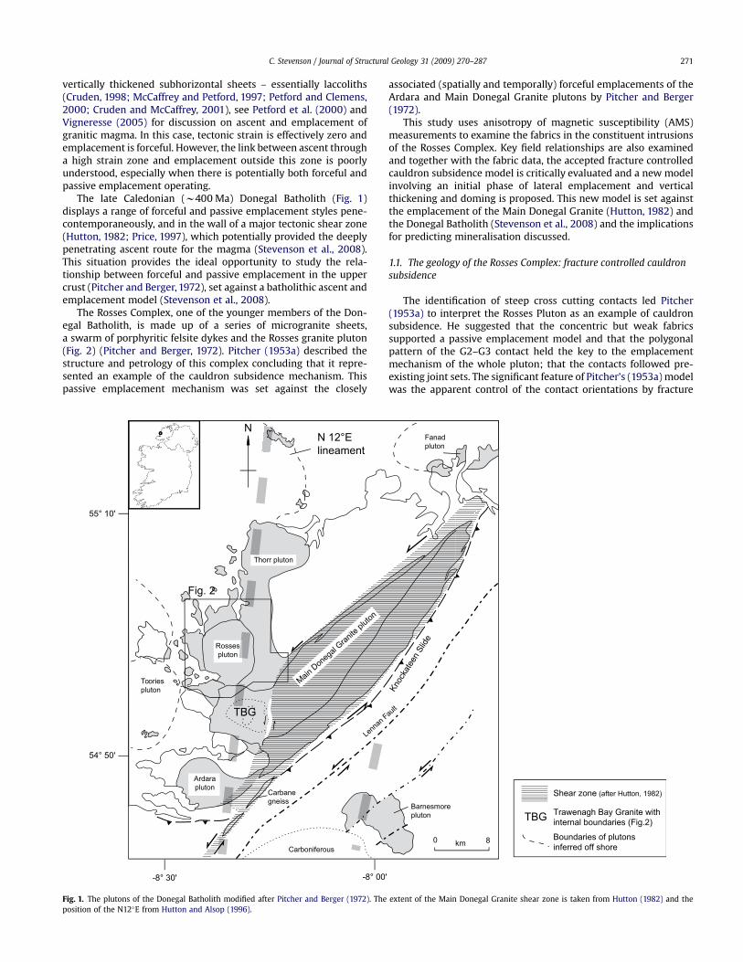
The late Caledonian (w400 Ma) Donegal Batholith (Fig. 1)displays a range of forceful and passive emplacement styles pene-contemporaneously, and in the wall of a major tectonic shear zone(Hutton, 1982; Price, 1997), which potentially provided the deeplypenetrating ascent route for the magma (Stevenson et al., 2008).This situation provides the ideal opportunity to study the rela-tionship between forceful and passive emplacement in the uppercrust (Pitcher and Berger, 1972), set against a batholithic ascent andemplacement model (Stevenson et al., 2008).
The Rosses Complex, one of the younger members of the Don-egal Batholith, is made up of a series of microgranite sheets,a swarm of porphyritic felsite dykes and the Rosses granite pluton(Fig. 2) (Pitcher and Berger, 1972). Pitcher (1953a) described thestructure and petrology of this complex concluding that it repre-sented an example of the cauldron subsidence mechanism. Thispassive emplacement mechanism was set against the closely
associated (spatially and temporally) forceful emplacements of theArdara and Main Donegal Granite plutons by Pitcher and Berger(1972).
This study uses anisotropy of magnetic susceptibility (AMS)measurements to examine the fabrics in the constituent intrusionsof the Rosses Complex. Key field relationships are also examinedand together with the fabric data, the accepted fracture controlledcauldron subsidence model is critically evaluated and a new modelinvolving an initial phase of lateral emplacement and verticalthickening and doming is proposed. This new model is set againstthe emplacement of the Main Donegal Granite (Hutton, 1982) andthe Donegal Batholith (Stevenson et al., 2008) and the implicationsfor predicting mineralisation discussed.
1.1. The geology of the Rosses Complex: fracture controlled cauldronsubsidence
The identification of steep cross cutting contacts led Pitcher(1953a) to interpret the Rosses Pluton as an example of cauldronsubsidence. He suggested that the concentric but weak fabricssupported a passive emplacement model and that the polygonalpattern of the G2–G3 contact held the key to the emplacementmechanism of the whole pluton; that the contacts followed pre-existing joint sets. The significant feature of Pitcher’s (1953a) modelwas the apparent control of the contact orientations by fracture
Rossespluton
Ardarapluton
Tooriespluton
Fanadpluton
N 12°Elineament
Fig. 2
Barnesmorepluton
Shear zone (after Hutton, 1982)
Trawenagh Bay Granite withinternal boundaries (Fig.2)
Boundaries of plutonsinferred off shore
Carbanegneiss
Lenn
an Fau
lt
Knoc
kate
en S
lide
Carboniferous
55° 10'
54° 50'
-8° 30' -8° 00'
0 8km
N
Thorr pluton
Main Don
egal
Granite
pluto
n
TBG
TBG
Fig. 1. The plutons of the Donegal Batholith modified after Pitcher and Berger (1972). The extent of the Main Donegal Granite shear zone is taken from Hutton (1982) and theposition of the N12�E from Hutton and Alsop (1996).
C. Stevenson / Journal of Structural Geology 31 (2009) 270–287 271
sets, where upward directed magma pressure exploited pre-exi-sting fractures or ‘master joints’ rather than instigating a newring-fault/dyke (Read, 1958); a modification of Anderson’s (1936)ring-dyke mechanism. Subsequent to Pitcher’s (1953a) work, pre-existing fracture controlled cauldron subsidence was established asan important emplacement mechanism in the Peruvian CoastalBatholith (Bussell et al., 1976; Cobbing et al., 1981; Cobbing andPitcher, et al., 1985; Pitcher, 1997, p. 202–246, 242; Bussell andPitcher, 1985; Haederle and Atherton, 2002) and elsewhere (e.g.Dehls et al., 1998; Lacroix et al., 1998; Chernicoff et al., 2002). TheRosses Complex was thus a seminal study for the Peruvian CoastalBatholith model and remains an important example of cauldronsubsidence and fracture controlled magma emplacement (see Hall,1966, p. 81; Pitcher, 1997, p. 202; Pitcher and Hutton, 2004, p. 60).
Hall (1966) suggested that the microgranite sheets representedthe initial fracturing of the roof of a magma chamber in the cauldron
subsidence emplacement model. He also postulated that thepartially radial disposition of the porphyry dykeswas due to inflationof an underlying magma chamber modified by east-west tensionalstresses. This has important implications in terms of understandingthe timing and circulation of mineralising fluids, as only the lateststages of the Rosses exhibit mineralisation (Pitcher, 1953a).
The petrology and the field relations of the various constituentparts of the Rosses Complex were studied in detail by Pitcher(1953a,b), Mercy (1962) and Hall (1966). The Rosses Pluton consistsof relatively homogeneous biotite–muscovite monzogranite witha roughly circular outcrop, w8.5 km in diameter emplaced entirelyinto the Thorr Pluton (Pitcher, 1953a,b) (Fig. 2). Pitcher (1953a)identified four separate, roughly concentric, units (G1–G4) in thepluton. These separate units were identified based mainly on thevariation of grain size and delineated by sharp but discontinuouscontacts sometimes characterised by accumulations of pegmatite
Fig. 2. The geology of the Rosses area modified after Pitcher (1953a). The metasedimentary xenoliths of the Thorr Pluton are omitted.
C. Stevenson / Journal of Structural Geology 31 (2009) 270–287272
or aplite. The G1 unit also contains a marginal G1A facies, which isessentially a finer grained variant of G1 and exhibits both transi-tional and cross cutting boundaries with some large microgranitesheets.
Pitcher (1953a) measured very weak fabrics in the RossesPluton, defined by biotite, in orientated thin sections of samplesfrom G1 and G2. These fabrics were generally parallel with thecontacts and, due to a lack of evidence for plastic deformation, ofmagmatic-state (Fig. 2).
The microgranite sheets are younger than the pluton and cropout within w3–4 km around the periphery in three main areas;around the northwest, in the east and a small area in the southwest.Pitcher (1953a) described a range of microgranite sheets; a darkbiotite rich variant, a pale biotite rich variant, a pale muscovite richvariant and a coarser porphyritic variant. Generally, the darkerbiotite rich variety is earliest and is usually cut by the paler sheets. Intheeast, three largemicrogranite sheets dipmoderatelynorth, strikeat a high angle to the margins of the pluton and are up to w70 mthickness. A significant feature of the largest sheet at Crovehy (alsopresent in the Pollcrovehy sheet) is its xenolith–strewn base or floor(near the southern contact). According to Pitcher (1953a), thexenolith rich portion of these sheets appears to be continuous withthe G1A facies that fringes the Rosses G1 in some eastern marginalareas (Fig. 2). Fabrics in these sheets are also very weak.
The porphyry dykes are feldspar- and biotite-pheric felsites.These dykes intrude the Rosses G1 and G2 units but are then cut bythe Rosses G3 unit.
Parts of the G3 unit and the whole G4 unit are characterised byareas of greisen and greisen veins. Pitcher (1953a) suggested thatthe same joint pattern that controlled the emplacement of theselast two units facilitated the circulation of late fluids.
Pitcher (1953a,b) described a number of enigmatic isolatedoutcrops of coarse grained quartz rich granite occurring in the areato the east of the pluton around the large microgranite sheets in
this area (Fig. 2). These coarse bodies are similar to the coarsegranite of the G2 unit in the Rosses Pluton.
2. Structural observations: new visible fabric data, fieldrelations and contact geometries
2.1. The Rosses Pluton
No new visible fabrics in the Rosses Pluton can be added to theobservations of Pitcher (1953a). The only new fabrics are thoserevealed by AMS analysis described below.
2.2. The Thorr Pluton
Although Pitcher (1953a) noted that the fabrics in the ThorrPluton were cut by the Rosses Pluton and are thus not related to itsemplacement, it is pointed out here that this is not generally true.
Fig. 3. Summary of the fabric trends in the Thorr Pluton and the contacts of the RossesPluton. The limit of deflection of Thorr fabrics close to the Rosses Pluton is highlightedwith a dashed line. The limit of deflection of fabrics in the Main Donegal shear zone ishighlighted with a dashed and dotted line. The latter may involve a combination ofboth of these strain fields and results in a tricuspid interference pattern in thesoutheast of the figure. Only in a small area along the western contact of the RossesPluton (highlighted with a dashed box) are Thorr fabrics truncated at a high angle ina similar way to the Trawenagh Bay Granite western contact to the south. Th – ThorrPluton; TBG – Trawenagh Bay Granite; MDG – Main Donegal Granite, RG1, 2, etc. –Rosses Granite G1, G2, etc.
Fig. 4. Stereographic projection showing the orientation of the microgranite sheets inthe three main areas.
Fig. 5. Sketch map of the contact relations of a dark microgranite sheet (DMG) cut bya pale microgranite sheet (PMG) (see Fig. 2 for location). Both of these intrude Thorrgranodiorite. Thin lines represent faint banding in the PMG. The offset of the DMGcontact across the PMG sheets is in a reverse sense. The strike/dip and dip direction isnoted for some contacts.
C. Stevenson / Journal of Structural Geology 31 (2009) 270–287 273
Fig. 6. (A) Photograph of a dark microgranite sheet, containing angular blocks of Thorr granodiorite. In detail, the margins are rounded–subrounded. (B) Close up of the margins oftwo of the granodiorite xenoliths showing the variation between sharp cross cutting (of the lower xenolith) and lobate and diffuse relationships (of the upper xenolith). Xenocrystsof Thorr feldspar are seen in the dark microgranite. (C) Close up of a xenocryst of feldspar in the microgranite. Note the irregular embayed contacts of the xenocryst.
Fig. 7. (A) Field photograph of an outcrop of microgranite from the Crovehy Sheet showing enclaves of a more biotite rich microgranite (highlighted with white arrows) elongatedroughly east-west (parallel with the hammer). (B) Field photograph of an outcrop of microgranite (roughly the same locality as A). Enclaves in this outcrop are flattened ina subhorizontal plane and elongated roughly east-west (parallel with the hammer). (C) Field photograph of microgranite (same locality) showing an internal contact (marked bywhite arrows) between a slightly coarser microgranite (pale) and a finer microgranite (darker). An enclave in the paler microgranite is truncated by the darker microgranite. Thiscontact trends roughly east-west.
C. Stevenson / Journal of Structural Geology 31 (2009) 270–287274
In Fig. 2, from Pitcher’s own data, Thorr fabrics in the east andsoutheast of the Rosses Pluton are disposed roughly parallel to theRosses Pluton contacts and fabrics in the northeast and northwestswing into at least partial parallelism with it (Fig. 3). Only in onesmall area on thewesternmargin are Thorr fabrics truncated by theRosses Pluton at a high angle. This is similar to the western contactof the Trawenagh Bay Granite western contact (Stevenson et al.,2007a). The microgranites usually cross cut Thorr magmatic- andsolid-state fabrics. Liquid–liquid relationships between Thorr andmicrogranites are also found (see below).
2.3. The microgranite sheets
The microgranite sheets in the northwest are usually between 1and 20 m thickness, strike NNW to NE (approximately tangential tothe margins of the Rosses Pluton) and always dip away from theRosses centre, although the amount of dip varies between 20 and85� (Fig. 4). Fabrics in the northwest microgranite sheets usuallystrike very roughly parallel with the margins of the sheets and dip
in the same direction but more steeply. These fabrics also seem tobe more consistently parallel with the margins of the Rosses Plutonthan the microgranite sheets. The pale microgranite sheets some-times exhibit contact parallel banding and when they cut darkersheets, they usually offset these sheets in a reverse sense (Fig. 5).
Xenoliths or enclaves are rare in the northwest sheets. However,xenoliths of Thorr tonalite have been discovered north of Kincas-slough at 55�201800N, 8�230W in dark microgranite sheets (Fig. 6).These xenoliths are up to w1 m in size and display a variety ofcontact relationships from sharp angular to lobate to gradational,even on the same xenolith. There are also plagioclase xenocrysts(displaying embayed margins) in the microgranite most likelyderived from the host tonalite. The significance of these observa-tions will be discussed below.
The eastern microgranite sheets contain biotite rich and musco-vite rich variants. The largest sheet at Crovehy contains all variantsand the sheet at Pollcrovehy contains mainly muscovite rich micro-granite. The northernmost sheet, Lettercau, has again both biotiteand muscovite rich variants. These sheets dip 20–40� north (Fig. 4).
A B
Fig. 8. (A) Map of the area just west of Toberkeen (see Fig. 2, contours are in feet). (B) Field photograph of an outcrop of a microgranite sheet (location indicated in part Awith a star)taken in the early evening when the low angle of the sun reveals the relief of smooth microgranite and rough (coarse grained) tonalite. Numerous xenoliths of tonalite are seen witha variety of angular to lobate shapes.
C. Stevenson / Journal of Structural Geology 31 (2009) 270–287 275
Fabrics in these sheets areweak and subhorizontal, although an east-west alignment of plagioclase is often observed. Theweakmagmatic-state fabric is reflected in a preferred orientation of xenoliths and raremafic enclaves of a finer grainedmicrogranodiorite, the lattermainlyin the Crovehy sheet, which in 3D are flattened in a roughly
subhorizontal planewith an east-west trending long axis (Fig. 7B). Inthese large sheets, subtle internal contacts are noticed indicating thatthese sheets are multiple (Fig. 7C).
At the southern margin of the largest sheet (Crovehy , location54�65’59’’N, 8�16’41’’W) a glacial pavement exposes a xenolith–
E
D
B C
A
Fig. 9. Visible fabric data from the porphyry dykes. (A) Sketch map showing the locations of where fabrics were measured in parts B–H. (B) Field photograph of the margin ofa porphyry dyke. A fabric defined mainly by biotite (highlighted with a dashed white line) is observed at an apparent low angle to the margin between the porphyry (Por) and Thorrgranodiorite (Th). (C) i. Stereographic projection of contacts (solid lines) and visible fabrics (dashed lines) measured at this locality; and ii. sketch map of the fabric–contactrelationships indicating a dextral sense of shear. (D and E) i. Stereographic projection of contacts (solid lines) and visible fabrics (dashed lines) measured at this locality; ii. sketchmap of the fabric–contact relationships indicating a dextral sense of shear; and iii. field photograph displaying these fabric–contact relationships. (F–I) i. Stereographic projection ofcontacts (solid lines) and visible fabrics (dashed lines) measured at this locality; and ii. sketch map of the fabric–contact relationships indicating a dextral sense of shear. (J)Stereographic projection of contacts (solid lines) and visible fabrics (dashed lines) measured at this locality. (K) Field photograph showing xenoliths of Thorr granodiorite displayinglobate contacts. This is the only locality in which these have been found.
C. Stevenson / Journal of Structural Geology 31 (2009) 270–287276
strewn base with gently dipping fabrics (see Supplementary map).Xenoliths are of Thorr granodiorite and a quartz rich granitoid ofunknown affinity. Xenoliths are aligned with their long axesparallel with strike of the microgranite sheet. The margin of thesheet cuts a mineral alignment in the Thorr at a high angle.Xenoliths of Thorr also display an internal fabric but this fabric isrotated and is aligned east-west parallel with the strike of the sheetand alignment of xenoliths. Pitcher (1953a) suggested the quartzrich granite xenoliths were related to a nearby stock, which cropsout w100 m perpendicular to strike. However, this cannot beconfirmed here as the east-west alignment and rotation of fabric of
the xenoliths suggests that they have been transported along strikein the microgranite. These quartz rich granitoid xenoliths could berelated to any other monzogranite of this Batholith.
In a few southerly locations of the Crovehy sheet, a steeplydipping east-west trending fabric is observed. This fabric is late as itdeforms all members of themicrogranites and late pegmatite dykesand is concomitant with deformation associated with the MainDonegal shear zone (Hutton, 1982; Stevenson et al., 2008).
In the southwest (between Dungloe and Toberkeen) there areseveral smallmicrogranite sheets and onemain sheet, which strikesroughly north–south and dips moderately west (Figs. 2 and 8).
N N
RP4
RP5
N
6mN
N
N
i.
i.
ii.
ii.
ii.
N
s
c 5mm
N
ii.
i.
i.
H
F G
I
JK
Fig. 9. (continued).
C. Stevenson / Journal of Structural Geology 31 (2009) 270–287 277
In this main sheet, a steeply dipping east-west trending fabric ismore obvious and is parallel with deformation associated witha splay of the Main Donegal Granite shear zone (Stevenson et al.,2008). In lower strain portions of this sheet a weak north–southfabric is preserved. Here, as in the northwest, xenoliths of Thorrtonalite exhibit a range of contact relationships from sharp angularto lobate to gradational (Fig. 6A and B).
2.4. Porphyry dykes
Visible fabrics are often oblique to the margins within a fewcentimetres of the margins (Fig. 9). These fabrics are defined bybiotite and plastically deformed feldspars and are therefore solid-state (e.g. Fig. 9B and Diii). The obliquity is usually consistent oneach margin of the same dyke indicating shearing by movement ofthe dyke walls (Berger, 1971). The sense of shear from shearedfabrics and offsets determined in dykes that trend NNW is dextral(e.g. Fig. 9B–E) and from those trending NNE it is sinistral (Fig. 9F–I).Not all dykes that exhibit offsets of earlier features exhibit solid-state fabrics (e.g. Fig. 9Eiii) suggesting that the dykes wereemplaced during the cessation or waning of a period of tectonicstrain.
3. Anisotropy of magnetic susceptibility
Anisotropy of magnetic susceptibility (AMS) can reveal thepreferred orientation of paramagnetic minerals and the preferredorientation and/or distribution of ferromagnetic minerals (princi-pally biotite and magnetite respectively). Thus, the orientation ofthe principal axes of the susceptibility ellipsoid can be used asa proxy for the orientation of mineral alignment fabrics and can bea powerful tool for constraining or defining very subtle fabrics in 3D(Tarling and Hrouda,1993; Bouchez,1997). However, because of thepotential conflicting contribution from different magnetic grains,direct strain analysis is very difficult and detailed petrologicalobservation and complimentary magnetic techniques (e.g. ther-momagnetic analysis) of the contributing mineralogy and theformation of any fabric is required before any conclusions can bedrawn concerning magma flow directions (e.g. Stevenson et al.,2007a; O’Driscoll et al., 2008).
The magnetic susceptibility tensor may be pictured as an ellip-soid with six independent quantities, which includes three prin-cipal susceptibility magnitudes, K1� K2� K3, and a corresponding
A
B
Fig. 10. (A) H plotted against K for all samples from the Rosses Complex. Data for eachunit has been outlined and background shaded in varying white to grey for clarity. (B)L/F plot for all samples from the Rosses Complex, symbols and outlines are as in part A.
Fig. 11. Susceptibility with varying temperature for three representative samples fromthe Rosses Complex. On each plot, the heating curve is in black and the cooling curve ingrey. The susceptibility (K) is shown for each sample. Heating curves indicate the Curietemperature of magnetite (w585 �C).
C. Stevenson / Journal of Structural Geology 31 (2009) 270–287278
set of three orthogonal principal axis directions. It is conventionalto recast the three magnitude parameters in terms of threeparameters, which together reflect the ‘‘size’’, ‘‘shape’’ and‘‘strength’’ (or ellipticity) of the ellipsoid. The three parametersadopted here (cf. Owens, 1974) are:
Kmean ¼ ðK1 þ K2 þ K3Þ=3
L ¼ ðK1�K2Þ=Kmean
F ¼ ðK2�K3Þ=Kmean
where Kmean is effectively the size, a plot of the magnetic lineation Lagainst the magnetic foliation F indicates graphically the shape ofthe ellipsoid where prolate ellipsoids lie near the L axis, oblateellipsoids near the F axis, triaxial ellipsoids occupy middle of theplot. Although the three quantities Kmean, L and F are sufficient todefine themagnitude parameters of the ellipsoid, it is convenient todefine another parameter, H¼ Lþ F¼ (K1� K3)/Kmean to indicatethe strength of the magnetic fabric.
In order to assess the AMS of the Rosses Complex a suite of 113oriented block samples in total were collected; 54 from the pluton,35 from themicrogranite sheets and 24 from the porphyry dykes. 6–12 sub-specimens were drilled from each sample in the lab by themethod outlined by Owens (1994) andmeasured on an AGICO KLY3-S Kappabridge (an induction bridge operating at a field of 377 mTanda frequency of 875 Hz) at the University of Birmingham. Results arereported for block averages of specimen AMS tensors, normalised byspecimenmean susceptibility, on the assumption that the specimens
from a block are representative of a homogeneous multinormalpopulation (Figs.10–17). The tensor-averaging process (Jelı́nek,1978;Owens, 2000) allows for the characterisation of within-block vari-ability through, for example, the calculation of 95% confidence limitson directions and magnitude parameters. The variation of suscepti-bility with temperature was measured using an AGICO CS-3 ovenattachment to the Kappabridge on powder samples of w2 g.
3.1. AMS results
The AMS results for all members of the Rosses Complex aredisplayed in Fig. 10 (and Supplementary table).
3.1.1. Microgranite sheetsSusceptibility (Kmean) values for the microgranite sheets are 8–
6339�10�6 (in theSI system)withHvaluesrangingbetween2and15%.Theshapeof anisotropy isgenerally in the triaxial–oblatefieldexcept fora fewsamples from the Crovehy sheet inwhich L ismuch greater than F.
3.1.2. Rosses PlutonSusceptibility values for G1 and G2 are 37–5257�10�6 (in the SI
values are 37–658� 10�6 with H values ranging between 1 and 5%.
3.1.3. Porphyry dykesKmean values for the porphyry dykes are 139–13124�10�6 with
H values ranging between 4 and 16%. The shape of anisotropy isgenerally in the oblate field.
N
4m
MG
MG
RP
55
55
65
65
N
microgranite
granodiorite
porphyry
N
A
B
C Magnetic foliation planes
Sheet margins
Fig. 12. (A) Field photograph showing the relationship between Thorr granodiorite, a microgranite sheet and a porphyry dyke. (B) Sketch map of the locality, dip of microgranite(mg) contacts is shown. AMS sample points are indicated and orientation data from these samples plotted stereographically; K1 axis – square, K2 axis – triangle and K3 – circle. Alsoplotted on the stereonets are great circles for the contacts: upper contact – solid black line, lower contact – solid grey line, and magnetic foliation – broken line. (C) 3D visualisationof the fabric geometry in the microgranite sheet displaying how the AMS foliation is subparallel to the contacts but strikes anticlockwise in the centre.
C. Stevenson / Journal of Structural Geology 31 (2009) 270–287 279
3.2. Magnetic minerals
The mineralogy of each member of the Rosses Complex isbroadly similar (Pitcher, 1953b; Mercy, 1962; Hall, 1966). Accessoryminerals in all members include oxides, identified from reflectedlight microscopy as magnetite or titanomagnetite with smallamounts of haematite.
Biotite has been identified as a fabric-forming phase in thisstudy and by Pitcher (1953b). However, thermomagnetic analysesreveal a step in the thermomagnetic (temperature vs. suscepti-bility) consistent with the curie temperature of magnetite con-firming magnetite is as a significant magnetic carrier (Fig. 11).Microscopic observations reveal that magnetite is usually associ-ated with biotite either growing close to the margins of biotitegrains or along cleavage planes. Stevenson et al. (2007a) estab-lished a mimetic relationship between biotite and magnetite forthe Trawenagh Bay Granite, where high-field susceptibilitymeasurements confirmed parallelism between paramagnetic andferromagnetic anisotropies, and heating experiments showed thatsecondary magnetite grew along biotite cleavage planes. Thus theAMS fabric orientation could be interpreted as essentiallycontrolled by the orientation of biotite across the range ofsusceptibility values. Given the similarities in mineralogy between
the Trawenagh Bay Granite and the Rosses Complex, the samefabric model is extended to this study.
4. AMS fabrics in the Rosses Complex
4.1. The microgranite sheets
Two main sheets were sampled in the northwest. The AMSfabrics in these sheets support the observation that visible fabricsdo not parallel the margins of the sheets. In sheet 1, north of Kin-casslough (Fig. 12), the magnetic foliations are parallel to themargins but strike w30� anticlockwise in the centre of the sheet(Fig. 12B). These AMS fabrics indicate a reverse-oblique-dextralsense of shear (Fig. 12C). In sheet 2, just west of Kincasslough(Fig. 13), AMS foliations are not consistently parallel to the sheetcontacts, but are parallel to the nearest contacts of the RossesPluton (Fig. 12C). AMS lineations in these sheets are orientatedbroadly down dip or oblique to dip.
In the larger eastern sheets, AMS foliations are usually gentlydipping or roughly subhorizontal, AMS lineations trend roughlyeast-west. Exceptions are in the southern most portions of theCrovehy sheet where the AMS foliations dip steeply and strike east-west (Fig. 14).
BA
C
Fig. 13. (A) Field photograph showing the upper contact of a microgranite sheet. (B) Field photograph showing the lower contact of the same sheet with the apparent dip of visiblefabric (feldspar alignment) indicated. (C) Sketch map of this locality (microgranite is grey). The dip of contacts is also shown. Indicated are AMS sample points and the orientationdata from these samples plotted stereographically (axis labelled as in Fig. 12). Note the dextral offset of microgranite across an NE striking porphyry dyke.
C. Stevenson / Journal of Structural Geology 31 (2009) 270–287280
In the southwest three samples were collected from the mainsheet. In the two most southerly samples, fabrics dip steeply andstrike east-west, consistent with the late cross cutting shear zonefabric. In the third sample, the fabric dips parallel with the contactof the sheet consistent with the early fabric (Fig. 15).
4.2. The Rosses Pluton
In G1 and G2, magnetic foliations are usually parallel with theouter contacts, consistent with the microscopic fabrics measuredby Pitcher (1953b), essentially defining a dome shaped pattern.Magnetic lineations are disposed roughly east-west about thedome shaped foliation pattern (Fig. 16). However, in G3 and G4magnetic fabrics are not well preserved.
4.3. Porphyry dykes
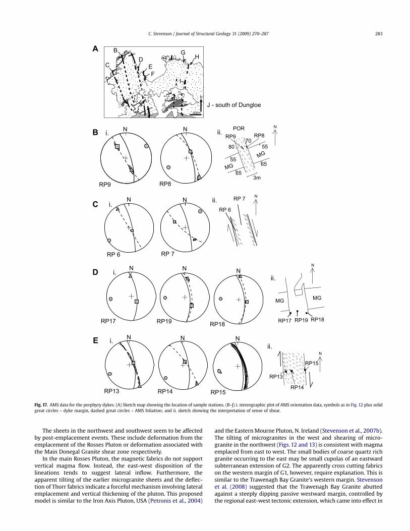
Magnetic foliations usually parallel the visible fabrics support-ing the obliquity to dyke margins (e.g. Fig. 17C,H and J). Those withno visible fabrics often show magnetic foliations that support thesense of shear of similarly orientated dykes, i.e. those orientedNNW are dextral, and those NNE are sinistral. Magnetic lineationsare much less consistently orientated, although this is unsurprisingconsidering the dominantly oblate magnetic fabric. Subsequently,
little can be drawn concerning magma flow or direction ofemplacement of these dykes.
5. Discussion: magma flow and deformation
The earliest components of the complex, the microgranitesheets in the east, contain gently dipping magmatic-state foliations(visible and magnetic) and east-west, gently plunging magneticlineations. These sheets seem to preserve an early stage of magmaemplacement where the sheets dip gently to moderatelynorthward.
The microgranite sheets in the northwest contain magneticfabrics that are consistently parallel to the margins of the mainRosses Pluton rather than the microgranite sheets. These fabricsmust have been imposed upon these sheets (post-emplacement) byforceful emplacement of the main Rosses Pluton. The dip of thesheets varies between w20� and w70� to the northwest. It may bethat these sheets represent an interconnected plexus of bridges andpartial bridges (e.g. Nicholson and Pollard, 1985). The variable dipreflects tilting during the emplacement of the Rosses Pluton so thatthey all now all dip northwest. The uniform strike of these sheetssuggests that their axes of disposition, deformation or tilting,possessed an apparently east-west trend indicating an east-westpropagation direction for these sheets.
N
750m
G1a
G1a
G1a
Crovehy
Pollcrovehy
Lettercau
Fig. 14. Sketch map of the microgranite sheets in the east. Lithology fills are as in Fig. 1. AMS data is plotted stereographically; symbols are as in Fig. 12. Note the generallysubhorizontal dip of the magnetic foliation and the east-west gently plunging lineation Star indicates the location of the Supplementary map.
C. Stevenson / Journal of Structural Geology 31 (2009) 270–287 281
Fig. 15. Sketch map of a microgranite sheet (grey) in the southwest, with visible fabric orientations marked with strike and dip bars and stereographic plots of AMS orientation data.Observed fabric trace in the Thorr granodiorite is marked with a dash. Note the steep magnetic foliations roughly parallel to visible fabrics, presumably tectonic related, and gentlydipping fabric from one AMS station parallel to the margin, possibly primary magmatic.
Fig. 16. Stereographic plot of AMS orientation data for the main Rosses Pluton. The margins of the internal units of the pluton are shown in outline and all other lithologies omittedfor clarity. Symbols are as in Fig. 12.
C. Stevenson / Journal of Structural Geology 31 (2009) 270–287282
The sheets in the northwest and southwest seem to be affectedby post-emplacement events. These include deformation from theemplacement of the Rosses Pluton or deformation associated withthe Main Donegal Granite shear zone respectively.
In the main Rosses Pluton, the magnetic fabrics do not supportvertical magma flow. Instead, the east-west disposition of thelineations tends to suggest lateral inflow. Furthermore, theapparent tilting of the earlier microgranite sheets and the deflec-tion of Thorr fabrics indicate a forceful mechanism involving lateralemplacement and vertical thickening of the pluton. This proposedmodel is similar to the Iron Axis Pluton, USA (Petronis et al., 2004)
and the EasternMourne Pluton, N. Ireland (Stevenson et al., 2007b).The tilting of microgranites in the west and shearing of micro-granite in the northwest (Figs. 12 and 13) is consistent with magmaemplaced from east to west. The small bodies of coarse quartz richgranite occurring to the east may be small cupolas of an eastwardsubterranean extension of G2. The apparently cross cutting fabricson the western margin of G1, however, require explanation. This issimilar to the Trawenagh Bay Granite’s western margin. Stevensonet al. (2008) suggested that the Trawenagh Bay Granite abuttedagainst a steeply dipping passive westward margin, controlled bythe regional east-west tectonic extension, which came into effect in
N N
RP 6 RP 7
RP9 RP8
N N
MG
MG
PORRP8RP9
55
65
55
65
3m
7080
N NN
RP17 RP18RP19 RP17 RP19 RP18
N N N
RP13 RP14
RP13
RP14
RP15
N
500m
N
A
DB
E
J - south of Dungloe
F
G
B i. ii.
CRP 6
RP 7i. ii.
D
MGMG
i.ii.
E i.ii.
RP15
N
N
N
CH
I
Fig. 17. AMS data for the porphyry dykes. (A) Sketch map showing the location of sample stations. (B–J) i. stereographic plot of AMS orientation data, symbols as in Fig. 12 plus solidgreat circles – dyke margin, dashed great circles – AMS foliation; and ii. sketch showing the interpretation of sense of shear.
C. Stevenson / Journal of Structural Geology 31 (2009) 270–287 283
the distal portion of the pluton that was fed from the east. It issuggested here that this may also account for the cross cuttingnature of this portion of the Rosses G1 margin.
The G3 and G4 units cannot easily be explained from this data.This is a similar situation to the G3 unit of the Trawenagh BayGranite, which Stevenson et al. (2007a) thought to be a cupolarelated to another sheet. Thismay be the case for the G3 and G4 unitsof the Rosses Pluton, where the fracture control envisaged by Pitcher(1953b) may apply at least to the more evolved and pegmatite richG3 unit. However, the sheet from which G3 emanated would besimilar in composition and texture to the G1 and G2 units.
Thus, the Rosses Complex was emplaced laterally from east towest. The major implication of this is that, like the Trawenagh BayGranite (Stevenson et al., 2007a, 2008), it was derived frommagmawithin the Main Donegal Granite. It is an example of lateral
emplacement of magma where the ascent was controlled bya major crustal shear zone – Main Donegal Granite – and was notdirectly subjacent.
The element of fracture control in the emplacement of thiscomplex has also been put into context. The initial and main stagesof emplacement involved the propagation and subsequent verticalthickening of subhorizontal sheets. Only the final stages ofemplacement (units G3 and G4 of the Rosses Pluton) may haveoccurred due to passive subsidence into a subjacent sheet.
This second phase of passive emplacement may have beenpreceded by the intrusion of the porphyry dykes, which record intheir visible and magnetic fabrics an east-west oriented extension.The transition from forceful to passive emplacement is possibly dueto a waning magma supply within a longer lived tensional strainfield. In the early stages, magma supply was such that magma
N
2mRP20 RP21 RP22
RP20
RP21
RP22
5m
N N N
RP1 RP2 RP3
RP1RP2
RP3
N N
RP4 RP5
RP4
RP5
N N
RP23 RP24
5m
N N N
Por
R
2cm
RP10 RP11 RP12
RP10
RP11
RP12
F i.ii.
N N N
N
N
G i. ii.
H i.ii.
I
N
J i. ii.
ii.N
5m
8m
Fig. 17. (continued).
C. Stevenson / Journal of Structural Geology 31 (2009) 270–287284
N~2 km
Coalescing sheetsform the MDG
initial sheets ofmicrograniteexit shear zone
B
1i
1
1ii
2
2
ESEWNW
B
3
3
4
5
4
5TBG
MDG
MDG
Unexposed sheets
~2 km
~2 km
N
N
Thorr
MDG
Inferred subsurface extent of ThorrCurrent day surface
shear zonesLineament controlled
through shear zoneDeeply penetrating ascent
C
D
A
Fig. 18. Final model. (A) 3D box diagram showing a portion of the floor of the Thorr Plutons and a large part of the Main Donegal Granite (MDG) at the time of the initialmicrogranite sheet emplacement extending vertically from the present day surface to w6–8 km. (B) Sketch cross section roughly corresponding to the SE side of the box of part A(and to roughly the same scale), showing the emplacement of each member of the Rosses Complex. 1 i and ii – microgranite sheets, 2 – G1, 3 – G2, 4 – porphyry dykes, 5 – G3 (insetshows G4). (C) Summary of map based on present day exposure level of the main forceful phase (parts B1–B3). Note that the Trawenagh Bay Granite to the south has not yet beenemplaced. Large open arrows show the regional east-west tensional tectonic strain. Smaller shear couple arrows show the main shear zones (after Stevenson et al., in press). Thickdashed line represents the postulated (unexposed today) extent of the microgranite sheets and G2. Strike bars with a dip barb demonstrate how the microgranite sheets and fabricsin G1 dip away from the forceful and substantive G2 dome. Thick arrows represent the interpreted magma flow pathways from AMS data. The line of section for part B is shown. (D)Summary of map based on present day exposure level of the main passive phase (parts B4– B5). Note that the Trawenagh Bay Granite to the south has now been emplaced sometimejust after the porphyry dykes (B4). All other arrows and symbols are as on part C.
C. Stevenson / Journal of Structural Geology 31 (2009) 270–287 285
pressure could overcome east-west tectonic extension and effecthorizontal fractures. As magma supply waned (or was switched toanother site) so too did magma pressure and vertical north–southtrending dykes were emplaced from subjacent sheets.
It is also noteworthy that the timing of emplacement of theThorr Pluton and Rosses Pluton does not seem to involve sucha large gap as has previously been accepted. The deflection of Thorrfabrics without any obvious solid-state strain plus the evidence forliquid–liquid relations between Thorr granodiorite and some of themicrogranite sheets suggests that there was actually a very short, ifnot overlapping, time gap. This is significant given that the ThorrPluton is regarded as the oldest member of the batholith whereasthe Rosses Complex is among the youngest (Pitcher and Berger,1972; Halliday et al., 1980; O’Connor et al., 1982).
Finally, the evidence presented here for lateral emplacementfrom outcrop data and fabric interpretation (both visible and fromAMS measurements), is at variance with the significant negativegravity anomaly centred over the Rosses Pluton (Young, 1974). Thissuggests a significant amount of low-density material (likelymonzo–leucogranite) beneath the Rosses, however, this need notbe the ascent route for Rosses magma. Instead, it could indicatea series of similar plutons to the Rosses in a Christmas tree laccolithstyle stack (cf. Corry, 1988; Rocchi et al., 2002). Each of these mayhave been emplaced laterally in a similar fashion to the Rosses,from the Main Donegal Granite, their positioning controlled bysome underlying lower crustal structure (Stevenson et al., 2008)(Fig. 18).
It is worth noting that the latest stage is the dominant miner-alising stage and is concomitant with passive fracture controlledemplacement allowing fluids to circulate. This fracture related styleof emplacement is crucial in the formation of significant epithermaland porphyry ore deposits as it allows fluids to circulate as well asproviding space for magma (e.g. Titley and Heidrick, 1978; Titleyet al., 1986;Williams et al., 1999; Garza et al., 2001; Chernicoff et al.,2002; Guillou-Frottier and Burov, 2003; Engvik et al., 2005; Garza-Gonzalez et al., 2006). Fluid inclusion studies by Conliffe and Feely(2006) identified a late magmatic fluid stage associated with berylmineralisation in the Rosses G3 and G4 greisen. They suggest thatthis fluid evolved by a pressure drop during cauldron subsidence. Ifthe entire complex was emplaced in this way, given the relativelyevolved nature of all the magmas involved, this mineralisation(together with associated pegmatite, aplite and greisens) should beassociated with all members of the complex. The model presentedhere helps to explain the timing and driving mechanism of thepressure drop within the overall emplacement model and will haveapplication in predicting mineralisation associated with this styleof granite emplacement.
6. Conclusions
The Rosses Complex was emplaced in four main stages (Fig. 18):the first two were lateral and forceful from east to west and thenthe third and fourth phases were dominantly passive and brittle,phase 4 at least arising from unexposed sheets emplaced duringphases 1 and 2.
Phase 1: A plexus of subhorizontal sheets of microgranite wasintruded east to west. These sheets appear to become generallythinner and more numerous proceeding east to west (Fig. 18A,B1iand B1ii).
Phase 2: The emplacement of G1 and G2 of the Rosses Pluton,which also occurred in an east to west direction. This pluton wasfed laterally by a largely unexposed conduit. Only small cupolas ofG2magma rising from this feeder conduit are exposed to the east ofthe pluton. The emplacement of the Rosses Plutonwas forceful as itdeflects fabrics in the surrounding Thorr Pluton and tilts and
deforms microgranite sheets in the northwest and west (Fig. 18B2and C).
Phase 3: This phase began with the intrusion of the porphyrydyke swarm, which record east-west extension. It is not clearwhere these sheets originate from but they may have a similarorigin to phase four in unexposed subjacent sheets (Fig. 18B3).
Phase 4: This dyke swarm is then followed by the emplacementof the G3 and G4 units of the Rosses Pluton, which are probablycupolas of a further sheet of the second phase. These cupolas werepassively emplaced and retain the fracture controlled mechanismof Pitcher (1953a) (Fig. 18B4,B5 and D).
Thus, the complete emplacement model involves ascentthrough a major shear zone and lateral emplacement into the wallof the shear zone.
Acknowledgments
This work was funded by doctoral programme at the Universityof Birmingham. Thanks to Donny Hutton for all his help and advice.The late Wally Pitcher is also thanked for his support and adviceduring the early stages of this work. John Reavy, Kerr Greenaway,Cathryn O’Connell and Ruth Hughes are all thanked for theirassistance in the field at various stages. Charles Green and familyare thanked for their hospitality during fieldwork in Dungloe. KeithBenn and Martin Feeley are thanked for insightful and constructivereviews that helped to significantly improve the manuscript.Finally, I would like to dedicate this paper to the memory of BillOwens, without whose patient supervision AMS would haveremained a mystery to me and many others. He will be sadlymissed.
Appendix. Supplementary data
Supplementary data associated with this article can be found, inthe online version, at doi:10.1016/j.jsg.2008.11.009.
References
Anderson, E.M., 1936. The dynamics of the formation of cone-sheets, ring-dykes andcaldron-subsidence. In: Proceedings of the Royal Society of Edinburgh, vol. 56128–157.
Berger, A.R., 1971. Dynamic analysis using dikes with oblique internal foliations.Geological Society of America Bulletin 82, 781–785.
Bouchez, J.L., 1997. Granite is never isotropic: an introduction to AMS studies ofgranitic rocks. In: Bouchez, J.L., Hutton, D.H.W., Stephens, W.E. (Eds.), Granite:from Segregation of Melt to Emplacement Fabrics, vol. 8. Kluwer AcademicPublishers, Dordrecht, pp. 95–112.
Brun, J.P., Pons, J., 1981. Strain patterns of pluton emplacement in a crust undergoingnon-coaxial deformation, Sierra-Morena, Southern Spain. Journal of StructuralGeology 3, 219–229.
Bussell, M.A., Pitcher, W.S., 1985. The structural control of batholith emplacement.In: Pitcher, W.S., Atherton, M.P., Cobbing, E.J., Beckinsale, R. (Eds.), Magmatismat a Plate Edge: the Peruvian Andes. Blackie, Glasgow, pp. 167–176.
Bussell, M.A., Pitcher, W.S., Wilson, P.A., 1976. Ring complexes of Peruvian CoastalBatholith – long-standing sub-volcanic regime. Canadian Journal of EarthSciences 13, 1020–1030.
Chernicoff, C.J., Richards, J.P., Zappettini, E.O., 2002. Crustal lineament control onmagmatism and mineralization in northwestern Argentina: geological,geophysical, and remote sensing evidence. Ore Geology Reviews 21, 127–155.
Cobbing, E.J., Pitcher, W.S., 1983. Andean plutonism in Peru and its relationship tovolcanism and metallogenesis at a segmented plate edge. Geological Society ofAmerica Memoirs 159, 277–291.
Cobbing, E.J., Pitcher, W.S., Wilson, J.J., Baldock, J.W., Taylor, W.P., McCourt, W.,Snelling, N.J., 1981. The Geology of the Western Cordillera of Northern Peru.HMSO, London.
Conliffe, J., Feely, M., 2006. Microthermometric characteristics of fluids associatedwith granite and greisen quartz, and vein quartz and beryl from the RossesGranite Complex, Donegal, NW Ireland. Journal of Geochemical Exploration 89,73–77.
Corry, C., 1988. Laccoliths: mechanisms of emplacement and growth. GeologicalSociety of America 220, 120. Special Paper.
C. Stevenson / Journal of Structural Geology 31 (2009) 270–287286
Cruden, A.R., 1998. On the emplacement of tabular granites. Journal of theGeological Society 155, 853–862.
Cruden, A.R., McCaffrey, K.J.W., 2001. Growth of plutons by floor subsidence:implications for rates of emplacement, intrusion spacing and melt-extractionmechanisms. Physics and Chemistry of the Earth Part A – Solid Earth andGeodesy 26, 303–315.
Dehls, J.F., Cruden, A.R., Vigneresse, J.L., 1998. Fracture control of late Archean plutonemplacement in the northern Slave Province, Canada. Journal of StructuralGeology 20, 1145–1154.
Engvik, A.K., Bertram, A., Kalthoff, J.F., Stockhert, B., Austrheim, H., Elvevold, S.,2005. Magma-driven hydraulic fracturing and infiltration of fluids into thedamaged host rock, an example from Dronning Maud Land, Antarctica. Journalof Structural Geology 27, 839–854.
Garza, R.A.P., Titley, S.R., Pimentel, F., 2001. Geology of the Escondida porphyrycopper deposit, Antofagasta region, Chile. Economic Geology and the Bulletin ofthe Society of Economic Geologists 96, 307–324.
Garza-Gonzalez, C., Camprubi, A., Gonzalez-Partida, E., Arriaga-Garcia, G., Rosique-Naranjo, F., 2006. Hydrothermal alteration and fluid inclusion study of thelower cretaceous porphyry Cu–Au deposit of Tiamaro, Michoacan, Mexico.GEOFLUIDS V: 5th International Conference on Fluid Evolution, Migration andInteraction in Sedimentary Basins and Orogenic Belts. Journal of GeochemicalExploration 89, 124–128.
Guillou-Frottier, L., Burov, E., 2003. The development and fracturing of plutonicapexes: implications for porphyry ore deposits. Earth and Planetary ScienceLetters 214, 341–356.
Haederle, M., Atherton, M.P., 2002. Shape and intrusion style of the Coastal Bath-olith, Peru. Tectonophysics 345, 17–28.
Hall, A., 1966. A petrogenetic study of Rosses Granite Complex Donegal. Journal ofPetrology 7, 202–220.
Halliday, A.N., Aftalion, M., Leake, B.E., 1980. A revised age for the Donegal Granites.Nature 284, 542–543.
Hutton, D.H.W., 1982. A tectonic model for the emplacement of the Main DonegalGranite, NW Ireland. Journal of the Geological Society, London 139, 615–631.
Hutton, D.H.W., 1988a. Igneous emplacement in a shear-zone termination – thebiotite granite at Strontian, Scotland. Geological Society of America Bulletin 100,1392–1399.
Hutton, D.H.W., 1988b. Granite emplacement mechanisms and tectonic controls:inferences from deformational studies. Transactions of the Royal Society ofEdinburgh – Earth Sciences 79, 245–255.
Hutton, D.H.W., 1992. Granite sheeted complexes – evidence for the dyking ascentmechanism. Transactions of the Royal Society of Edinburgh – Earth Sciences 83,377–382.
Hutton, D.H.W., 1996. The ‘space problem’ in the emplacement of granite. Episodes19, 114–119.
Hutton, D.H.W., Alsop, G.I., 1996. The Caledonian strike-swing andassociated lineaments in NW Ireland and adjacent areas: sedimentation,deformation and igneous intrusion patterns. Journal of the Geological Society153, 345–360.
Ingram, G.M., Hutton, D.H.W., 1994. The great tonalite sill – emplacement intoa contractional Shear Zone and implications for late cretaceous to early eocenetectonics in Southeastern Alaska and British Columbia. Geological Society ofAmerica Bulletin 106, 715–728.
Jacques, J.M., Reavy, R.J., 1996. Caledonian plutonism and major lineaments in theSW Scottish highlands. Journal of the Geological Society 151, 955–969.
Jelı́nek, V., 1978. Statistical processing of anisotropy of magnetic susceptibilitymeasured on groups of specimens. Studia Geophysica et Geodaetica 22, 50–62.
Lacroix, S., Sawyer, E.W., Chown, E.H., 1998. Pluton emplacement within anextensional transfer zone during dextral strike-slip faulting: an examplefrom the late Archaean Abitibi Greenstone Belt. Journal of Structural Geology 20,43–59.
Mahan, K.H., Bartley, J.M., Coleman, D.S., Glazner, A.F., Carl, B.S., 2003. Sheetedintrusion of the synkinematic McDoogle pluton, Sierra Nevada, California.Geological Society of America Bulletin 115, 1570–1582.
McCaffrey, K.J.W., 1992. Igneous emplacement in a transpressive shear zone: OxMountains igneous complex. Journal of the Geological Society 149, 221–235.
McCaffrey, K.J.W., Petford, N., 1997. Are granitic intrusions scale invariant? Journal ofthe Geological Society 154, 1–4.
Mercy, E.L.P., 1962. The mullaghduff porphyry dyke. Transactions of the RoyalSociety of Edinburgh – Earth Sciences 19, 65–82.
Nicholson, R., Pollard, D.D., 1985. Dilation and linkage of echelon cracks. Journal ofStructural Geology 7, 583–590.
O’Connor, P.J., Long, C.B., Keenan, P.S., Halliday, A.N., Max, M.D., Roddick, J.C., 1982.Rb–Sr isochron study of the Thorr and Main Donegal Granites, Ireland.Geological Journal 17, 279–295.
O’Driscoll, B., Stevenson, C.E., Troll, V.R., 2008. Mineral lamination development inlayered gabbros of the British palaeogene igneous province: a combinedanisotropy of magnetic susceptibility, quantitative textural and mineral chem-istry study. Journal of Petrology 49, 1187–1221.
Owens, W.H., 1974. Mathematical model studies on factors affecting the magneticanisotropy of deformed rocks. Tectonophysics 24, 115–131.
Owens, W.H., 2000. Error estimates in the measurement of anisotropic magneticsusceptibility. Geophysical Journal International 142, 516–526.
Petford, N., Clemens, J.D., 2000. Granites are not diapiric!. Geology Today, 180–184.Petford, N., Cruden, A.R., McCaffrey, K.J.W., Vigneresse, J.L., 2000. Granite magma
formation, transport and emplacement in the earth’s crust. Nature 408,669–673.
Petronis, M.S., Hacker, D.B., Holm, D.K., Geissman, J.W., Harlan, S.S., 2004. Magmaticflow paths and palaeomagnetism of the Miocene Stoddard Mountain laccolith,iron axis region Southwestern Utah, USA. In: Martin-Hernandez, F., Luneburg,C.M., Aubourg, C., Jackson, M. (Eds.), Magnetic Fabric: Methods and Applica-tions. Geological Society, London, Special Publications, vol. 238, pp. 251–284.
Pitcher, W.S., 1953a. The Rosses granitic ring complex, County Donegal. In:Proceedings of the Geologists’ Association, vol. 64 153–182.
Pitcher, W.S., 1953b. The migmatitic older granodiorite of the Thorr District, Co.Donegal. Quarterly Journal of the Geological Society of London 108, 413–446.
Pitcher, W.S., 1997. The Nature and Origin of Granite. Chapman and Hall, London.Pitcher, W.S., Atherton, M.P., Cobbing, E.J., Beckinsale, R., 1985. Magmatism at a Plate
Edge: the Peruvian Andes. Blackie, Glasgow, pp. 328.Pitcher, W.S., Berger, A.R., 1972. The Geology of Donegal, a Study of Granite
Emplacement and Unroofing. Wiley Interscience, London.Pitcher, W.S., Hutton, D.H.W., 2004. A Master Class Guide to the Granites of Donegal.
The Geological Survey of Ireland, Dublin.Price, A.R., 1997. Multiple Sheeting as a Mechanism of Pluton Construction: the
Main Donegal Granite, NW. Ireland. Unpublished PhD thesis, University ofDurham.
Read, H.H., 1958. Donegal granite. Science in Progress 182, 225–240.Reavy, R.J., 1989. Structural controls on metamorphism and syn-tectonic magma-
tism – the Portuguese Hercynian collision belt. Journal of the Geological Society146, 649–657.
Richey, J.E., 1928. Structural relations of the Mourne Granites (Northern Ireland).Quarterly Journal of the Geological Society of London 83, 653.
Richey, J.E., 1932. Tertiary ring structures in Britain. Transactions of the GeologicalSociety of Glasgow 88, 776.
Rocchi, S., Westerman, D.S., Dini, A., Innocenti, F., Tonarini, S., 2002. Two-stagegrowth of laccoliths at Elba Island, Italy. Geology 30, 983–986.
Stevenson, C.T.E., Owens, W.H., Hutton, D.H.W., 2007a. Flow lobes in granite: thedetermination of magma flow direction in the Trawenagh Bay Granite, N.W.Ireland, using anisotropy of magnetic susceptibility. Geological Society ofAmerica Bulletin.
Stevenson, C.T.E., Owens, W.H., Hutton, D.H.W., Hood, D.N., Meighan, I.G., 2007b.Laccolithic as opposed to cauldron subsidence emplacement of the EasternMourne pluton, N. Ireland: evidence from anisotropy of magnetic susceptibility.Journal of the Geological Society, London 164, 99–110.
Stevenson, C.T.E., Hutton, D.H.W., Price, A.R., 2008. The Trawenagh Bay Granite anda new model for the emplacement of the Donegal Batholith. Transactions of theRoyal Society of Edinburgh – Earth Sciences 97, 455–477.
Tarling, D.H., Hrouda, F., 1993. The Magnetic Anisotropy of Rocks. Chapman andHall, New York.
Titley, S.R., Heidrick, T.L., 1978. Intrusion and fracture styles of some mineralizedporphyry systems of Southwestern Pacific and their relationship to plateinteractions. Economic Geology 73, 891–903.
Titley, S.R., Thompson, R.C., Haynes, F.M., Manske, S.L., Robison, L.C., White, J.L.,1986. Evolution of fractures and alteration in the Sierrita–Esperanza hydro-thermal system, Pima County, Arizona. Economic Geology 81, 343–370.
Vigneresse, J.L., 2005. A new paradigm for granite generation. Transactions of theRoyal Society of Edinburgh – Earth Sciences 95, 11–22.
Williams, W.C., Meissl, E., Madrid, J., de Machuca, B.C., 1999. The San Jorge porphyrycopper deposit, Mendoza, Argentina: a combination of orthomagmatic andhydrothermal mineralization. Ore Geology Reviews 14, 185–201.
Young, D.G.G., 1974. Donegal granite – gravity analysis. In: Proceedings of the RoyalIrish Academy Section B-Biological Geological and Chemical Science, vol. 7463–73.
C. Stevenson / Journal of Structural Geology 31 (2009) 270–287 287